US6980150B2 - System and method for controlling home appliances - Google Patents
System and method for controlling home appliancesDownload PDFInfo
- Publication number
- US6980150B2 US6980150B2US10/827,137US82713704AUS6980150B2US 6980150 B2US6980150 B2US 6980150B2US 82713704 AUS82713704 AUS 82713704AUS 6980150 B2US6980150 B2US 6980150B2
- Authority
- US
- United States
- Prior art keywords
- key
- keypad
- command
- recited
- remote control
- Prior art date
- Legal status (The legal status is an assumption and is not a legal conclusion. Google has not performed a legal analysis and makes no representation as to the accuracy of the status listed.)
- Expired - Lifetime, expires
Links
- 238000000034methodMethods0.000titleclaimsdescription13
- 230000008054signal transmissionEffects0.000claimsabstractdescription14
- 230000004913activationEffects0.000claimsdescription14
- 230000005540biological transmissionEffects0.000claimsdescription8
- 230000006870functionEffects0.000claimsdescription6
- 230000004044responseEffects0.000description10
- 241000282668CebusSpecies0.000description5
- 230000008901benefitEffects0.000description3
- 238000010586diagramMethods0.000description3
- 230000003213activating effectEffects0.000description2
- 230000008859changeEffects0.000description1
- 238000001816coolingMethods0.000description1
- 230000000694effectsEffects0.000description1
- 239000004744fabricSubstances0.000description1
- 238000010438heat treatmentMethods0.000description1
- 238000012986modificationMethods0.000description1
- 230000004048modificationEffects0.000description1
- 230000003287optical effectEffects0.000description1
- 230000001360synchronised effectEffects0.000description1
Images


Classifications
- G—PHYSICS
- G08—SIGNALLING
- G08C—TRANSMISSION SYSTEMS FOR MEASURED VALUES, CONTROL OR SIMILAR SIGNALS
- G08C23/00—Non-electrical signal transmission systems, e.g. optical systems
- G08C23/04—Non-electrical signal transmission systems, e.g. optical systems using light waves, e.g. infrared
- G—PHYSICS
- G08—SIGNALLING
- G08C—TRANSMISSION SYSTEMS FOR MEASURED VALUES, CONTROL OR SIMILAR SIGNALS
- G08C17/00—Arrangements for transmitting signals characterised by the use of a wireless electrical link
- G08C17/02—Arrangements for transmitting signals characterised by the use of a wireless electrical link using a radio link
- G—PHYSICS
- G08—SIGNALLING
- G08C—TRANSMISSION SYSTEMS FOR MEASURED VALUES, CONTROL OR SIMILAR SIGNALS
- G08C2201/00—Transmission systems of control signals via wireless link
- G08C2201/20—Binding and programming of remote control devices
- G—PHYSICS
- G08—SIGNALLING
- G08C—TRANSMISSION SYSTEMS FOR MEASURED VALUES, CONTROL OR SIMILAR SIGNALS
- G08C2201/00—Transmission systems of control signals via wireless link
- G08C2201/30—User interface
- G08C2201/33—Remote control using macros, scripts
- G—PHYSICS
- G08—SIGNALLING
- G08C—TRANSMISSION SYSTEMS FOR MEASURED VALUES, CONTROL OR SIMILAR SIGNALS
- G08C2201/00—Transmission systems of control signals via wireless link
- G08C2201/40—Remote control systems using repeaters, converters, gateways
Definitions
- This inventionrelates generally to remote controls and, more particularly, relates to a system and method for using a remote control to control home appliances.
- remote controlsit is known in the art to use remote controls to control the operation of home appliances. Furthermore, it is known in the art to provide remote controls with macro command capabilities whereby one or more user selected control commands can be transmitted to one or more home appliances in response to activation of a single remote control key.
- U.S. Pat. No. 5,959,751 to Darbee, et al., issued on Sep. 28, 1999 and entitled “Universal Remote Control Device,”discloses a remote control with programming that allows a user to define a sequence of operations that the remote control will perform in response to activation of a macro key on the remote control. The user defines the sequence of operations by placing the remote control into a macro definition mode and, thereafter, activating one or more keys on the remote control.
- the remote controlWhen the macro key is subsequently activated, the remote control will perform the operations that have been assigned to the one or more keys that were activated during the macro definition mode.
- the operations performed by the remote control in response to activation of the macro keycan include sending control commands to one or more home appliances for the purpose of controlling the operation of the home appliance(s).
- the “Smart” line of products offered by General Electricprovides a system for integrating existing home appliances, such as audio/video, heating and cooling, security, lighting, and other voltage products, into a control network.
- the integrated control networkcan be programmed to include “house macros” that allows multiple control commands to be issued to one or more home appliances attached to the network.
- the “house macro” control commandsare issued to the home appliances in response to the activation of “smart switches” that are connected to the integrated control network.
- CEBus protocolis the underlying protocol for the messages that are routed throughout the integrated control network. Message routing is performed by a system manager that has no direct physical connection to the home appliances. Rather, the system manager sends CEBus protocol messages to the home appliances over standard powerlines. Within the system manager is stored the programming for the system level functions (i.e., house macros, light scenes, master clock, etc.) that determine which control commands are transmitted to the home appliances residing on the network.
- the subject inventionis directed to improved system and method for controlling one or more home appliances.
- the systemincludes a keypad and a relay unit. At least one key on the keypad is associated with at least one command code from a plurality of command codes stored in a memory.
- the systemdetermines if the at least one key on the keypad has been activated or if a command signal transmission that identifies the at least one key on the keypad has been received from the relay unit. When it is determined that either the at least one key has been activated or the command signal transmission that identifies the at least one key has been received, the system communicates to the one or more of home appliances the one or more command codes that have been associated to the at least one key on the keypad.
- FIG. 1illustrates an exemplary system including relay units in communication with a remote control having command codes for use in controlling the operation of home appliances;
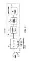
- FIG. 2illustrates a block diagram of an exemplary embodiment of the relay units of FIG. 1 ;
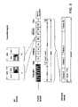
- FIG. 3illustrates an exemplary signal format for use in communicating with the remote control of FIG. 1 ;
- FIG. 4illustrates a block diagram of an exemplary embodiment of the remote control of FIG. 1 ;
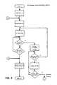
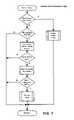
- FIGS. 5–7illustrate flow chart diagrams of an exemplary method for controlling the operation of home appliances.
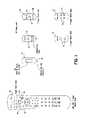
- the systemincludes a remote control 10 and relay units 12 that include one or more buttons 14 as illustrated in FIG. 1 .
- Each of the buttons 14corresponds to one of the command keys on the remote control 10 .
- the command keycan be a simple key such as “MUTE,” it is preferred that the command key be a user definable macro key 16 .
- activation of a button 14 on a relay unit 12will cause the remote control 10 to perform the operations that have been assigned to the key that corresponds to the activated button 14 .
- These operationwill typically include the transmitting of one or more command codes to one or more home appliances for the purpose of controlling the operation of the home appliance(s).
- the remote control 10is adapted to transmit command codes to remotely controllable home appliances.
- the remote control 10includes a microprocessor 20 that is in communication with a memory 22 , a keypad 24 , and an infrared (“IR”) transmitter 26 .
- the keypad 24comprised of a plurality of keys, is coupled to the microprocessor 20 for, among other things, allowing the user to command the operation of the remote control 10 .
- the keypad keysinclude number keys, function keys, mode keys, and macro keys 16 . While described in the context of physical keys on the remote control 10 , the keypad 24 can be implemented virtually using touch screens or the like.
- the memory 22includes executable instructions that are intended to command the operation of the microprocessor 20 .
- the executable instructionsallow the microprocessor 20 to control the various electronic components within the remote control 10 , e.g., to control power, to cause the transmission of command codes, etc.
- the memory 22may be comprised of any type of computer-readable media, such as ROM, RAM, SRAM, FLASH, EEPROM, or the like.
- the memory 22comprises non-volatile forms of memory such as ROM, Flash, or battery-backed SRAM such that programmed and user entered data is not required to be reloaded after battery changes.
- the memory 22may take the form of a chip, a smart card, a hard disk, a magnetic disk, and/or an optical disk.
- the memory 22also includes a command code library.
- the command code libraryis comprised of a plurality of command codes that may be transmitted from the remote control 10 directly to a home appliance to control the operation of the home appliance (e.g., to cause a TV to mute, to change a CD track, etc.).
- the memory 22includes instructions and data which the microprocessor 20 uses to cause the IR transmitter 26 to transmit the command codes in a format that is recognized by identifiable home appliances. As described in U.S. Pat. No.
- a usermay enter data into the remote control 10 that serves to identify home appliances by type and manufacturer such that the remote control 10 is adapted to transmit the appropriate command codes in the appropriate format for such identified home appliances.
- a usermay “teach” the remote control the codes of another unit as described in U.S. Pat. No. 4,626,848 to Ehlers issued Dec. 2, 1986 which is also incorporated herein by reference in its entirety. Combinations of these two techniques are also possible.
- the usermay activate one or more keys on the keypad 24 .
- certain of the keysare mapped to certain of the executable instructions stored within the memory 24 .
- the executable instructionsmay cause the remote control 10 to transmit command codes to one or more home appliances in accordance with the data the user has entered to setup the remote control or has taught the remote control 10 in response to activation of a key.
- Home appliancesthat are especially adapted for remote control include TVs, VCRs, DVD players, thermostats, fans, entry systems, computers, etc.
- the executable instructionscan also be used to perform local operations on the remote control itself in response to activation of a key. Examples of local operation include favorite key setup, macro key setup, etc.
- the remote control 10includes executable instructions that are used to place the remote control 10 into a macro entry definition mode.
- the macro entry definition modeallows a user to define a sequence of operations that the remote control will perform in response to activation of a selected one of the macro keys 16 .
- the userdefines a sequence of operations and identifies the macro key 16 to which the sequence of operations are to be assigned.
- the sequence of operationsmay be defined by activating one or more command/function keys on the remote control 10 .
- the remote control 10will perform the operations that have been defined for the macro key 16 .
- the remote control 10is adapted to respond to command signals that are transmitted to the remote control 10 by the relay units 12 .
- the remote control 10includes a radio frequency (“RF”) receiver 28 which is in communication with the microprocessor 20 by way of data lines 30 and interrupt line 32 .
- the RF receiver 28includes an RF antenna 34 , a wireless signal receiver circuit 36 , a control circuit 38 , and a wakeup timer 40 . Since the operation of the RF receiver 28 is described in detail in commonly owned U.S. Pat. Nos. 5,638,050 and 5,686,891, which are incorporated herein by reference in their entirety, it will not be described herein for the sake of brevity.
- the relay units 12include an RF transmitter 42 as illustrated in FIG. 2 .
- the RF transmitter 42includes a modulation oscillator circuit 44 , a signal voltage regulator circuit 46 and an RF oscillator circuit 48 as well as a RF antenna.
- the RF transmitter 42is under the control of a microcontroller 50 which is in communication with the button(s) 14 .
- the microcontroller 50also includes a memory having the instructions and data necessary to allow the RF transmitter 42 to communicate the command signals to the remote control 10 . Since the operation of the RF transmitter 42 is also described in detail in commonly owned U.S. Pat. Nos. 5,638,050 and 5,686,891, it will not be described herein for the sake of brevity.
- the relay units 12For communicating the command signals to the remote control 10 , the relay units 12 preferably use a “Manchester” bit encoding schema.
- the “Manchester” encoding schemais preferred since a carrier signal is present for each bit of data transmitted, i.e., without regard to whether the bit has a value of “0” or “1.”
- use of the “Manchester” encoding schemaensures that there is never a period of longer than some predetermined time during the transmission that a carrier signal is not present.
- the longest time period that could occur without a carrier during signal transmissionwould be 40 mS when the bit codes “0” followed by “1” are transmitted.
- the use of the “Manchester” encoding schemais particularly useful as it allows the remote control 10 to wake up periodically to check for a command signal transmission from the relay units 12 .
- a burst of carrier which is longer than the predetermined timecan be used as a transmission preamble.
- the longest time period that could occur with a bit signal transmissionwould be 40 mS when the bit codes “1” followed by “0” are transmitted.
- a burst of carrier for longer than 40 mSe.g., 140 mS
- the command signal transmitted to the remote control 10 from the relay unit 12preferably includes a 4-bit address.
- each of the buttons 14will have a unique address associated therewith.
- this addresscomprises two bits of button number information (i.e. up to four distinct buttons) and two bits of “system” code (i.e. up to four distinct systems).
- the purpose of the “system” codeis to permit the co-existence of multiple remote controls which are within RF range of one another—for example in adjacent homes or offices, or even several independent units in the same home.
- the addresscan be preset or could be configured by the user by way ofjumpers or switches 52 as illustrated in FIG. 2 . It will be appreciated that while a 4-bit address is used in the embodiment shown, in the event more than four buttons or more than four system codes are required the number of bits in the address can easily be extended as appropriate.
- the remote control 10For causing the remote control to perform an operation in response to the receipt of a command signal transmitted by the relay units 12 , the remote control 10 includes programming that examines the 4-bit addresses received and, if the system code portion matches the value assigned to the remote, maps the button number portion of the address to selected operations of the remote control 10 .
- the addressesare mapped to the operation(s) that have been defined to the macro keys 16 . Accordingly, upon receipt of a command signal, the remote control will perform the operation(s) that were defined for the macro key 16 that corresponds to the address in the signal transmitted.
- These operationscan include the transmission of one or more command codes from the remote control 10 to one or more of the home appliances.
- the relay unit 12transmits to the remote control 10 a five second long command signal.
- the command signalcontains ten identical frames each of which includes address data comprising a system code and the identity of the button 14 that was activated, e.g., “1 ”when button “1” is activated.
- Each data framealso includes a preamble burst which enables the RF receiver 28 to synchronize with the command signal transmission.
- the RF receiver 28To detect the transmission of a command signal, the RF receiver 28 is caused to wake up once every four seconds. The four second time frame is used as it allows at least one complete frame of data to be received no matter where in the transmission cycle the RF receiver 28 awakes. When the RF receiver 28 wakes up, if a command signal is not detected within 50 mS the remote control 10 goes back to sleep and waits for the next wake up interrupt. If, however, the RF receiver 28 detects the transmission of the command signal, the RF receiver 28 begins to monitor for an RF carrier signal of longer than 45 mS which indicates the presence of the preamble.
- the RF receiver 28assumes that the signal was a data pulse (i.e., an address bit) and the RF receiver 28 continues to monitor for a new RF carrier signal which is expected within 50 mS. When an RF carrier signal of longer than 45 mS is detected, then a preamble burst is present and the RF receiver 28 synchronizes itself to the end of the preamble burst. If no preamble burst is detected within 500 mS, or if at any time there is a 50 mS gap with no RF activity, an error condition is determined to be present within the system.
- a data pulsei.e., an address bit
- the RF receiver 28decodes the address data and the error check data embedded within the command signal. If the address data is successfully decoded and no error condition exists, the address data is latched to the data lines 30 and an interrupt signal is sent to the microprocessor 20 on interrupt line 32 . Upon receiving an interrupt signal, the microprocessor 20 responds according to whether the interrupt was generated as a result of activation of a key on the keypad 24 or as a result of signal reception by the RF receiver 28 .
- the microprocessor 20causes the remote control 10 to perform the operation(s) that have been mapped/assigned to the activated key. If, however, the interrupt was generated by the RF receiver 28 , the microprocessor 20 reads the address information from the data line 30 . If the system code portion of the address matches that of the remote control, the microprocessor 20 uses the button number information from the address to cause the remote control 10 to perform the operation(s) that have been mapped/assigned to the address in the received command signal.
- the microprocessor 20will cause the remote control 10 to perform the same operation(s) as if the macro key 16 corresponding to the address was directly activated. In this example, the remote control 10 would perform the operation(s) that were assigned to macro key “1.”
- the relay units 12are particularly adapted to be carried on a key chain and or attached to a wall. In this manner, the user can communicate with the remote control 10 to control the operation of home appliances at various locations within the household.
- the relay units 12can include an optional key ring connector 60 .
- the relay units 12can include a “velcro” strip 62 that is adapted to engage a fabric strip that is adhered to the wall.
- the relay units 12can also include flanges with openings by which the relay units 12 can be mounted to the wall using fasteners such as nails or screws.
- buttons 14 on the relay units 12 and the keys of the remote control 10can be indicated to the user by way of labels that are placed on the buttons 14 and the keys (e.g., labels “1” through “4”).
- the labelscan be preprinted on the buttons and/or keys. Alternately, printed labels can be adhered to the relay units 12 and/or the remote control 10 . It will also be appreciated that, while described in the context of physical keys on the relay unit 12 , the buttons 14 can be implemented virtually using touch screens or the like.
- relay unitsare described in the context of self-contained devices, it will be appreciated that these may also be built into other items from which access to pre-defined home appliance functions is desired, for example a cordless telephone handset, a nightstand, an alarm clock, etc.
- the relay units 12can be equipped with simple timers such as kitchen timers.
- the usercan program a count down time or time of day at which time the command signal will be transmitted to the remote control 10 .
- the relay unitwill include a timer display 64 and buttons 66 for programming the timer and for informing the relay unit 12 which address is to be included in a transmitted command signal, i.e., if more than one button 14 and/or address is supported by the relay unit 12 .
- the subject system and method for controlling home applianceshas the advantage of providing a low cost solution to home appliance control. Specifically, the subject system and method does not require the use of specialized communications modules that need to be hardwired to conventional home appliances. This desirable result arises from the use of the remote control 10 which is adapted to communicate with the home appliances through free space using signal formats that conventional home appliances already recognize.
Landscapes
- Physics & Mathematics (AREA)
- General Physics & Mathematics (AREA)
- Engineering & Computer Science (AREA)
- Computer Networks & Wireless Communication (AREA)
- Selective Calling Equipment (AREA)
- Cookers (AREA)
Abstract
Description
Claims (14)
Priority Applications (1)
| Application Number | Priority Date | Filing Date | Title |
|---|---|---|---|
| US10/827,137US6980150B2 (en) | 2001-03-14 | 2004-04-19 | System and method for controlling home appliances |
Applications Claiming Priority (2)
| Application Number | Priority Date | Filing Date | Title |
|---|---|---|---|
| US09/808,708US6724339B2 (en) | 2001-03-14 | 2001-03-14 | System and method for controlling home appliances |
| US10/827,137US6980150B2 (en) | 2001-03-14 | 2004-04-19 | System and method for controlling home appliances |
Related Parent Applications (1)
| Application Number | Title | Priority Date | Filing Date |
|---|---|---|---|
| US09/808,708ContinuationUS6724339B2 (en) | 2001-03-14 | 2001-03-14 | System and method for controlling home appliances |
Publications (2)
| Publication Number | Publication Date |
|---|---|
| US20040246165A1 US20040246165A1 (en) | 2004-12-09 |
| US6980150B2true US6980150B2 (en) | 2005-12-27 |
Family
ID=25199487
Family Applications (2)
| Application Number | Title | Priority Date | Filing Date |
|---|---|---|---|
| US09/808,708Expired - LifetimeUS6724339B2 (en) | 2001-03-14 | 2001-03-14 | System and method for controlling home appliances |
| US10/827,137Expired - LifetimeUS6980150B2 (en) | 2001-03-14 | 2004-04-19 | System and method for controlling home appliances |
Family Applications Before (1)
| Application Number | Title | Priority Date | Filing Date |
|---|---|---|---|
| US09/808,708Expired - LifetimeUS6724339B2 (en) | 2001-03-14 | 2001-03-14 | System and method for controlling home appliances |
Country Status (9)
| Country | Link |
|---|---|
| US (2) | US6724339B2 (en) |
| EP (1) | EP1371044B1 (en) |
| AT (1) | ATE279764T1 (en) |
| AU (1) | AU2002245502B2 (en) |
| BR (1) | BR0207721A (en) |
| DE (1) | DE60201587T2 (en) |
| ES (1) | ES2231676T3 (en) |
| MX (1) | MXPA03008084A (en) |
| WO (1) | WO2002073566A2 (en) |
Cited By (22)
| Publication number | Priority date | Publication date | Assignee | Title |
|---|---|---|---|---|
| US20040090461A1 (en)* | 2002-10-31 | 2004-05-13 | Adams Guy De Warrenne Bruce | Interface devices |
| US20040160534A1 (en)* | 2003-02-17 | 2004-08-19 | Elitegroup Computer Systems Co., Ltd. | TV image conversion device for turning computer on or off by means of multimedia remote control |
| US20070018878A1 (en)* | 2005-07-25 | 2007-01-25 | Ron Tolmei | Activation of remote control transmitter functions by external inputs |
| US20070019654A1 (en)* | 2003-05-30 | 2007-01-25 | Lg Electronics, Inc. | Home network system |
| US20070046814A1 (en)* | 2005-08-31 | 2007-03-01 | Fujitsu Limited | Signal seperation circuit and signal transmission circuit |
| US20090100474A1 (en)* | 2007-10-16 | 2009-04-16 | Microsoft Corporation | Remote control based output selection |
| US7612685B2 (en) | 2000-03-15 | 2009-11-03 | Logitech Europe S.A. | Online remote control configuration system |
| US8026789B2 (en) | 2000-03-15 | 2011-09-27 | Logitech Europe S.A. | State-based remote control system |
| US8090309B2 (en) | 2004-10-27 | 2012-01-03 | Chestnut Hill Sound, Inc. | Entertainment system with unified content selection |
| US8195114B2 (en) | 2004-10-27 | 2012-06-05 | Chestnut Hill Sound, Inc. | Entertainment system with bandless content selection |
| US8509400B2 (en) | 2005-04-20 | 2013-08-13 | Logitech Europe S.A. | System and method for adaptive programming of a remote control |
| US8508401B1 (en) | 2010-08-31 | 2013-08-13 | Logitech Europe S.A. | Delay fixing for command codes in a remote control system |
| US8531276B2 (en) | 2000-03-15 | 2013-09-10 | Logitech Europe S.A. | State-based remote control system |
| US9614553B2 (en) | 2000-05-24 | 2017-04-04 | Enocean Gmbh | Energy self-sufficient radiofrequency transmitter |
| USRE46499E1 (en)* | 2001-07-03 | 2017-08-01 | Face International Corporation | Self-powered switch initiation system |
| US9852615B2 (en) | 2011-03-25 | 2017-12-26 | Universal Electronics Inc. | System and method for facilitating appliance control via a smart device |
| US11126397B2 (en) | 2004-10-27 | 2021-09-21 | Chestnut Hill Sound, Inc. | Music audio control and distribution system in a location |
| US11640760B2 (en) | 2011-03-25 | 2023-05-02 | Universal Electronics Inc. | System and method for appliance control via a network |
| US12073711B2 (en) | 2011-10-28 | 2024-08-27 | Universal Electronics Inc. | System and method for optimized appliance control |
| US12154428B2 (en) | 2005-09-08 | 2024-11-26 | Universal Electronics Inc. | System and method for widget-assisted setup of a universal remote control |
| US12192559B2 (en) | 2011-09-22 | 2025-01-07 | Universal Electronics Inc. | System and method for configuring controlling device functionality |
| US12307884B2 (en) | 2011-10-28 | 2025-05-20 | Universal Electronics Inc. | Systems and methods for associating services and/or devices with a voice assistant |
Families Citing this family (94)
| Publication number | Priority date | Publication date | Assignee | Title |
|---|---|---|---|---|
| US7283059B2 (en)* | 2000-03-15 | 2007-10-16 | Logitech Europe S.A. | Remote control multimedia content listing system |
| US7424291B1 (en)* | 2001-01-24 | 2008-09-09 | Palmsource, Inc. | Method and system for enabling timed events of a portable computing device to trigger remote control of external devices |
| US20030197595A1 (en)* | 2002-04-22 | 2003-10-23 | Johnson Controls Technology Company | System and method for wireless control of multiple remote electronic systems |
| US6998955B2 (en)* | 2002-08-09 | 2006-02-14 | Ballew Michael A | Virtual electronic remote control device |
| US20060164932A1 (en)* | 2002-09-18 | 2006-07-27 | Bright Entertainment Limited | Media control unit for providing interactive experience with audiovisual content of dvd |
| US7003598B2 (en)* | 2002-09-18 | 2006-02-21 | Bright Entertainment Limited | Remote control for providing interactive DVD navigation based on user response |
| US20050060238A1 (en)* | 2002-11-01 | 2005-03-17 | Pushplay Interactive, Llc | Controller and peripheral user interface (pui) for media event |
| US20040140998A1 (en)* | 2002-11-01 | 2004-07-22 | Gravina Craig S. | Controller and removable user interface (rui) for controlling media event |
| US20070180387A1 (en)* | 2002-11-01 | 2007-08-02 | Pushplay Interactive, Llc | Devices and methods for controlling media event |
| WO2004077729A2 (en) | 2003-02-21 | 2004-09-10 | Johnson Controls Technology Company | Trainable remote controller and method for determining the frequency of a learned control signal |
| US8174357B2 (en)* | 2002-11-08 | 2012-05-08 | Johnson Controls Technology Company | System and method for training a transmitter to control a remote control system |
| WO2004043750A2 (en) | 2002-11-08 | 2004-05-27 | Johnson Controls Technology Company | Trainable transceiver system |
| US20040125075A1 (en)* | 2002-12-31 | 2004-07-01 | Diercks Richard A. | DVD remote control with interchangeable, title-specific interactive panels |
| US7183941B2 (en)* | 2003-07-30 | 2007-02-27 | Lear Corporation | Bus-based appliance remote control |
| US7269416B2 (en)* | 2003-07-30 | 2007-09-11 | Lear Corporation | Universal vehicle based garage door opener control system and method |
| US7161466B2 (en) | 2003-07-30 | 2007-01-09 | Lear Corporation | Remote control automatic appliance activation |
| US7068181B2 (en)* | 2003-07-30 | 2006-06-27 | Lear Corporation | Programmable appliance remote control |
| US7039397B2 (en)* | 2003-07-30 | 2006-05-02 | Lear Corporation | User-assisted programmable appliance control |
| US20060261999A1 (en)* | 2003-08-25 | 2006-11-23 | Mabry John D | Universal remote |
| US7518495B2 (en)* | 2003-11-18 | 2009-04-14 | Lear Corporation | Universal tire pressure monitor |
| US7589642B1 (en)* | 2003-12-16 | 2009-09-15 | Uei Cayman Inc. | Relaying key code signals through a remote control device |
| US7441062B2 (en) | 2004-04-27 | 2008-10-21 | Apple Inc. | Connector interface system for enabling data communication with a multi-communication device |
| US7441058B1 (en)* | 2006-09-11 | 2008-10-21 | Apple Inc. | Method and system for controlling an accessory having a tuner |
| US7673083B2 (en)* | 2004-04-27 | 2010-03-02 | Apple Inc. | Method and system for controlling video selection and playback in a portable media player |
| US7634605B2 (en)* | 2004-04-27 | 2009-12-15 | Apple Inc. | Method and system for transferring stored data between a media player and an accessory |
| US8117651B2 (en) | 2004-04-27 | 2012-02-14 | Apple Inc. | Method and system for authenticating an accessory |
| US7529870B1 (en)* | 2004-04-27 | 2009-05-05 | Apple Inc. | Communication between an accessory and a media player with multiple lingoes |
| US7826318B2 (en)* | 2004-04-27 | 2010-11-02 | Apple Inc. | Method and system for allowing a media player to transfer digital audio to an accessory |
| US7526588B1 (en) | 2004-04-27 | 2009-04-28 | Apple Inc. | Communication between an accessory and a media player using a protocol with multiple lingoes |
| US7529872B1 (en) | 2004-04-27 | 2009-05-05 | Apple Inc. | Communication between an accessory and a media player using a protocol with multiple lingoes |
| US7895378B2 (en)* | 2004-04-27 | 2011-02-22 | Apple Inc. | Method and system for allowing a media player to transfer digital audio to an accessory |
| US7797471B2 (en)* | 2004-04-27 | 2010-09-14 | Apple Inc. | Method and system for transferring album artwork between a media player and an accessory |
| EP1789939A1 (en)* | 2004-09-01 | 2007-05-30 | Wilfried Beck | Device and method for operating adjustable and controllable household appliances with the aid of a multipart remote control |
| US20070180479A1 (en)* | 2004-10-20 | 2007-08-02 | Bright Entertainment Limited | Interactive video on demand (ivod) |
| US7823214B2 (en)* | 2005-01-07 | 2010-10-26 | Apple Inc. | Accessory authentication for electronic devices |
| US20060161690A1 (en)* | 2005-01-19 | 2006-07-20 | John Kavanagh | Remote device configuration automation |
| US8606950B2 (en)* | 2005-06-08 | 2013-12-10 | Logitech Europe S.A. | System and method for transparently processing multimedia data |
| US7870232B2 (en)* | 2005-11-04 | 2011-01-11 | Intermatic Incorporated | Messaging in a home automation data transfer system |
| US20070256085A1 (en)* | 2005-11-04 | 2007-11-01 | Reckamp Steven R | Device types and units for a home automation data transfer system |
| US7694005B2 (en) | 2005-11-04 | 2010-04-06 | Intermatic Incorporated | Remote device management in a home automation data transfer system |
| US20070121653A1 (en)* | 2005-11-04 | 2007-05-31 | Reckamp Steven R | Protocol independent application layer for an automation network |
| US7640351B2 (en)* | 2005-11-04 | 2009-12-29 | Intermatic Incorporated | Application updating in a home automation data transfer system |
| US7698448B2 (en)* | 2005-11-04 | 2010-04-13 | Intermatic Incorporated | Proxy commands and devices for a home automation data transfer system |
| EP1966778B1 (en)* | 2005-12-22 | 2011-10-26 | Koninklijke Philips Electronics N.V. | Remote control extension with limited command duration |
| US20070233731A1 (en)* | 2006-02-22 | 2007-10-04 | Logitech Europe S.A. | System and method for configuring media systems |
| US7589613B2 (en) | 2006-04-03 | 2009-09-15 | Lear Corporation | Trinary to trinary rolling code generation method and system |
| US8006019B2 (en) | 2006-05-22 | 2011-08-23 | Apple, Inc. | Method and system for transferring stored data between a media player and an accessory |
| US20070299999A1 (en)* | 2006-06-21 | 2007-12-27 | Vicky Duerk | Link protocol control for serial protocols |
| US7415563B1 (en) | 2006-06-27 | 2008-08-19 | Apple Inc. | Method and system for allowing a media player to determine if it supports the capabilities of an accessory |
| US7558894B1 (en) | 2006-09-11 | 2009-07-07 | Apple Inc. | Method and system for controlling power provided to an accessory |
| US9293032B2 (en)* | 2006-12-29 | 2016-03-22 | Echostar Technologies L.L.C. | Two-way communication for control of an entertainment device |
| US20080169899A1 (en)* | 2007-01-12 | 2008-07-17 | Lear Corporation | Voice programmable and voice activated vehicle-based appliance remote control |
| KR101504115B1 (en)* | 2007-03-12 | 2015-03-19 | 삼성전자 주식회사 | Macro instruction operation device and macro instruction input device and method |
| US8086781B2 (en)* | 2007-06-22 | 2011-12-27 | Apple Inc. | Serial pass-through device |
| US8078787B2 (en) | 2007-06-22 | 2011-12-13 | Apple Inc. | Communication between a host device and an accessory via an intermediate device |
| CN103112324B (en) | 2007-07-03 | 2016-01-27 | 欧陆汽车系统美国有限公司 | universal tire pressure monitoring sensor |
| US8047966B2 (en)* | 2008-02-29 | 2011-11-01 | Apple Inc. | Interfacing portable media devices and sports equipment |
| CA2726151C (en)* | 2008-05-30 | 2016-11-22 | Koninklijke Philips Electronics N.V. | Round illumination device |
| US9202372B2 (en)* | 2008-06-27 | 2015-12-01 | Echostar Technologies L.L.C. | Systems and methods for remote control setup |
| US8238811B2 (en) | 2008-09-08 | 2012-08-07 | Apple Inc. | Cross-transport authentication |
| US8208853B2 (en) | 2008-09-08 | 2012-06-26 | Apple Inc. | Accessory device authentication |
| US8427356B1 (en) | 2008-11-28 | 2013-04-23 | Uei Cayman Inc. | Automatic determination and retrieval of a favorite channel |
| US8400344B2 (en)* | 2009-02-20 | 2013-03-19 | Echostar Technologies L.L.C. | Methods and apparatus for learning remote control commands |
| US8909803B2 (en) | 2009-03-16 | 2014-12-09 | Apple Inc. | Accessory identification for mobile computing devices |
| US8452903B2 (en) | 2009-03-16 | 2013-05-28 | Apple Inc. | Mobile computing device capabilities for accessories |
| US10198935B2 (en) | 2009-12-08 | 2019-02-05 | Universal Electronics Inc. | System and method for simplified activity based setup of a controlling device |
| US20110167176A1 (en)* | 2010-01-06 | 2011-07-07 | Apple Inc. | Connecting multiple accessories to a portable computing device |
| FR2956757B1 (en)* | 2010-02-25 | 2012-09-21 | Somfy Sas | ASSIGNING SCENARIOS TO CONTROL BUTTONS. |
| US9786159B2 (en) | 2010-07-23 | 2017-10-10 | Tivo Solutions Inc. | Multi-function remote control device |
| CN101945493B (en)* | 2010-09-14 | 2014-10-22 | 中兴通讯股份有限公司 | Intelligent home network system, control device and method |
| US8233803B2 (en) | 2010-09-30 | 2012-07-31 | Transmitive, LLC | Versatile remote control device and system |
| FR2966627B1 (en)* | 2010-10-26 | 2012-12-21 | Somfy Sas | METHOD FOR OPERATING A MOBILE CONTROL UNIT OF A DOMOTIC INSTALLATION |
| US8751092B2 (en) | 2011-01-13 | 2014-06-10 | Continental Automotive Systems, Inc. | Protocol protection |
| US8918544B2 (en) | 2011-03-31 | 2014-12-23 | Logitech Europe S.A. | Apparatus and method for configuration and operation of a remote-control system |
| US9239837B2 (en) | 2011-04-29 | 2016-01-19 | Logitech Europe S.A. | Remote control system for connected devices |
| EP2741930B1 (en) | 2011-08-09 | 2015-11-18 | Continental Automotive Systems, Inc. | Protocol misinterpretation avoidance apparatus and method for a tire pressure monitoring system |
| US8576060B2 (en) | 2011-08-09 | 2013-11-05 | Continental Automotive Systems, Inc. | Protocol arrangement in a tire pressure monitoring system |
| US9676238B2 (en) | 2011-08-09 | 2017-06-13 | Continental Automotive Systems, Inc. | Tire pressure monitor system apparatus and method |
| EP2741928B1 (en) | 2011-08-09 | 2019-10-09 | Continental Automotive Systems, Inc. | Tire pressure monitoring apparatus and method |
| CN103874592B (en) | 2011-08-09 | 2018-01-30 | 大陆汽车系统公司 | Device and method for activating a positioning procedure of a tire pressure monitor |
| CN102325279A (en)* | 2011-08-22 | 2012-01-18 | 朱筱华 | Electrical control panel based on the wifi network |
| US9306879B2 (en) | 2012-06-08 | 2016-04-05 | Apple Inc. | Message-based identification of an electronic device |
| US20150208135A1 (en) | 2012-06-14 | 2015-07-23 | Flextronics Ap, Llc | Methods and displays for providing intelligent television badges |
| CN103828388A (en)* | 2012-08-17 | 2014-05-28 | 弗莱克斯电子有限责任公司 | Methods and displays for providing intelligent television badges |
| CN103152502A (en)* | 2013-03-06 | 2013-06-12 | 刘洋宏 | Telephone remote control module |
| KR20150019805A (en)* | 2013-08-16 | 2015-02-25 | 삼성전자주식회사 | Controlling Method For Input Status and Electronic Device supporting the same |
| CN103499960B (en)* | 2013-10-09 | 2016-05-11 | 广东索博智能科技有限公司 | Intelligent household wireless control system |
| US9446636B2 (en) | 2014-02-26 | 2016-09-20 | Continental Automotive Systems, Inc. | Pressure check tool and method of operating the same |
| US9373250B2 (en)* | 2014-12-30 | 2016-06-21 | Smk Electronics Corporation | Remote controller having one shot automatic mapping of learned function |
| US9517664B2 (en) | 2015-02-20 | 2016-12-13 | Continental Automotive Systems, Inc. | RF transmission method and apparatus in a tire pressure monitoring system |
| DE102016213290A1 (en) | 2015-08-03 | 2017-02-09 | Continental Automotive Systems, Inc. | Apparatus, system and method for configuring a tire information sensor with a transmission protocol based on vehicle trigger characteristics |
| US11209912B2 (en)* | 2016-12-06 | 2021-12-28 | Rohde & Schwarz Gmbh & Co. Kg | Measuring device and configuration method |
| CN109462095A (en)* | 2018-11-10 | 2019-03-12 | 慈溪市栋电子有限公司 | 433M Digiplex controlled wireless remote control socket |
| CN113284331B (en)* | 2021-03-16 | 2023-04-11 | 杭州当贝网络科技有限公司 | Projection interactive system |
Citations (6)
| Publication number | Priority date | Publication date | Assignee | Title |
|---|---|---|---|---|
| US4656655A (en)* | 1984-10-23 | 1987-04-07 | Hashimoto Corporation | Remote control adapter of electric equipment using telephone lines |
| US5227780A (en)* | 1989-03-16 | 1993-07-13 | Houston Satellite Systems, Inc. | Apparatus with a portable UHF radio transmitter remote for controlling one or more of infrared controlled appliances |
| US5986644A (en)* | 1997-07-30 | 1999-11-16 | Selectech, Ltd. | Remote control system |
| US6225938B1 (en)* | 1999-01-14 | 2001-05-01 | Universal Electronics Inc. | Universal remote control system with bar code setup |
| US20010005197A1 (en)* | 1998-12-21 | 2001-06-28 | Animesh Mishra | Remotely controlling electronic devices |
| US6640144B1 (en)* | 2000-11-20 | 2003-10-28 | Universal Electronics Inc. | System and method for creating a controlling device |
Family Cites Families (14)
| Publication number | Priority date | Publication date | Assignee | Title |
|---|---|---|---|---|
| JPH0710091B2 (en)* | 1986-10-24 | 1995-02-01 | ソニー株式会社 | Electronics |
| DE3819863A1 (en)* | 1987-06-12 | 1989-01-05 | Matsushita Electric Industrial Co Ltd | REMOTE CONTROL DEVICE FOR ELECTRONIC DEVICES |
| US5228077A (en)* | 1987-12-02 | 1993-07-13 | Universal Electronics Inc. | Remotely upgradable universal remote control |
| US4959810A (en) | 1987-10-14 | 1990-09-25 | Universal Electronics, Inc. | Universal remote control device |
| ATE127604T1 (en) | 1988-05-04 | 1995-09-15 | Vogel Peter S | REMOTE CONTROL. |
| US4882747A (en)* | 1988-05-12 | 1989-11-21 | Jerry Williams | Infrared communication apparatus for remote site applications |
| US5138649A (en)* | 1990-11-16 | 1992-08-11 | General Instrument Corporation | Portable telephone handset with remote control |
| JP3588385B2 (en) | 1994-05-10 | 2004-11-10 | 三星電子株式会社 | Remote control system |
| IT1284524B1 (en)* | 1996-09-13 | 1998-05-21 | Zetesis Spa | USE OF PROTEINS AS ANTI-RETROVIRAL AGENTS |
| US6181255B1 (en)* | 1997-02-27 | 2001-01-30 | The Chamberlain Group, Inc. | Multi-frequency radio frequency transmitter with code learning capability |
| US5963624A (en) | 1997-12-05 | 1999-10-05 | Zilog, Inc. | Digital cordless telephone with remote control feature |
| US6249673B1 (en)* | 1998-11-09 | 2001-06-19 | Philip Y. W. Tsui | Universal transmitter |
| EP1109393A1 (en) | 1999-12-17 | 2001-06-20 | Siemens Aktiengesellschaft | Remote control equipment for use with a telecommunication network |
| KR20020019607A (en) | 2000-06-09 | 2002-03-12 | 요트.게.아. 롤페즈 | Modular remote control device |
- 2001
- 2001-03-14USUS09/808,708patent/US6724339B2/ennot_activeExpired - Lifetime
- 2002
- 2002-02-21ESES02713664Tpatent/ES2231676T3/ennot_activeExpired - Lifetime
- 2002-02-21ATAT02713664Tpatent/ATE279764T1/ennot_activeIP Right Cessation
- 2002-02-21EPEP02713664Apatent/EP1371044B1/ennot_activeExpired - Lifetime
- 2002-02-21DEDE60201587Tpatent/DE60201587T2/ennot_activeExpired - Lifetime
- 2002-02-21WOPCT/US2002/005373patent/WO2002073566A2/ennot_activeApplication Discontinuation
- 2002-02-21BRBR0207721-3Apatent/BR0207721A/ennot_activeApplication Discontinuation
- 2002-02-21MXMXPA03008084Apatent/MXPA03008084A/enunknown
- 2002-02-21AUAU2002245502Apatent/AU2002245502B2/ennot_activeExpired - Fee Related
- 2004
- 2004-04-19USUS10/827,137patent/US6980150B2/ennot_activeExpired - Lifetime
Patent Citations (6)
| Publication number | Priority date | Publication date | Assignee | Title |
|---|---|---|---|---|
| US4656655A (en)* | 1984-10-23 | 1987-04-07 | Hashimoto Corporation | Remote control adapter of electric equipment using telephone lines |
| US5227780A (en)* | 1989-03-16 | 1993-07-13 | Houston Satellite Systems, Inc. | Apparatus with a portable UHF radio transmitter remote for controlling one or more of infrared controlled appliances |
| US5986644A (en)* | 1997-07-30 | 1999-11-16 | Selectech, Ltd. | Remote control system |
| US20010005197A1 (en)* | 1998-12-21 | 2001-06-28 | Animesh Mishra | Remotely controlling electronic devices |
| US6225938B1 (en)* | 1999-01-14 | 2001-05-01 | Universal Electronics Inc. | Universal remote control system with bar code setup |
| US6640144B1 (en)* | 2000-11-20 | 2003-10-28 | Universal Electronics Inc. | System and method for creating a controlling device |
Cited By (48)
| Publication number | Priority date | Publication date | Assignee | Title |
|---|---|---|---|---|
| US8742905B2 (en) | 2000-03-15 | 2014-06-03 | Logitech Europe S.A. | Easy to use and intuitive user interface for a remote control |
| US8854192B1 (en) | 2000-03-15 | 2014-10-07 | Logitech Europe S.A. | Configuration method for a remote |
| US8531276B2 (en) | 2000-03-15 | 2013-09-10 | Logitech Europe S.A. | State-based remote control system |
| US8797149B2 (en) | 2000-03-15 | 2014-08-05 | Logitech Europe S.A. | State-based control systems and methods |
| US8674814B2 (en) | 2000-03-15 | 2014-03-18 | Logitech Europe S.A. | State-based remote control system |
| US7612685B2 (en) | 2000-03-15 | 2009-11-03 | Logitech Europe S.A. | Online remote control configuration system |
| US8704643B2 (en) | 2000-03-15 | 2014-04-22 | Logitech Europe S.A. | Convenient and easy to use button layout for a remote control |
| US8330582B2 (en) | 2000-03-15 | 2012-12-11 | Logitech Europe S.A. | Online remote control configuration system |
| US8674815B1 (en) | 2000-03-15 | 2014-03-18 | Logitech Europe S.A. | Configuration method for a remote |
| US7944370B1 (en) | 2000-03-15 | 2011-05-17 | Logitech Europe S.A. | Configuration method for a remote control via model number entry for a controlled device |
| US8653950B2 (en) | 2000-03-15 | 2014-02-18 | Logitech Europe S.A. | State-based remote control system |
| US8026789B2 (en) | 2000-03-15 | 2011-09-27 | Logitech Europe S.A. | State-based remote control system |
| US9887711B2 (en) | 2000-05-24 | 2018-02-06 | Enocean Gmbh | Energy self-sufficient radiofrequency transmitter |
| US9614553B2 (en) | 2000-05-24 | 2017-04-04 | Enocean Gmbh | Energy self-sufficient radiofrequency transmitter |
| USRE46499E1 (en)* | 2001-07-03 | 2017-08-01 | Face International Corporation | Self-powered switch initiation system |
| US20040090461A1 (en)* | 2002-10-31 | 2004-05-13 | Adams Guy De Warrenne Bruce | Interface devices |
| US20040160534A1 (en)* | 2003-02-17 | 2004-08-19 | Elitegroup Computer Systems Co., Ltd. | TV image conversion device for turning computer on or off by means of multimedia remote control |
| US7098968B2 (en)* | 2003-02-17 | 2006-08-29 | Elitegroup Computer Systems, Co., Ltd. | TV image conversion device for turning computer on or off by means of multimedia remote control |
| US20070019654A1 (en)* | 2003-05-30 | 2007-01-25 | Lg Electronics, Inc. | Home network system |
| US8725063B2 (en) | 2004-10-27 | 2014-05-13 | Chestnut Hill Sound, Inc. | Multi-mode media device using metadata to access media content |
| US8843092B2 (en) | 2004-10-27 | 2014-09-23 | Chestnut Hill Sound, Inc. | Method and apparatus for accessing media content via metadata |
| US10310801B2 (en) | 2004-10-27 | 2019-06-04 | Chestnut Hill Sound, Inc. | Media entertainment system with fail-safe alarm modes |
| US10114608B2 (en) | 2004-10-27 | 2018-10-30 | Chestnut Hill Sound, Inc. | Multi-mode media device operable in first and second modes, selectively |
| US8355690B2 (en) | 2004-10-27 | 2013-01-15 | Chestnut Hill Sound, Inc. | Electrical and mechanical connector adaptor system for media devices |
| US8195114B2 (en) | 2004-10-27 | 2012-06-05 | Chestnut Hill Sound, Inc. | Entertainment system with bandless content selection |
| US8090309B2 (en) | 2004-10-27 | 2012-01-03 | Chestnut Hill Sound, Inc. | Entertainment system with unified content selection |
| US8655303B2 (en) | 2004-10-27 | 2014-02-18 | Chestnut Hill Sound, Inc. | Entertainment system with sourceless selection including playlists |
| US9225773B2 (en) | 2004-10-27 | 2015-12-29 | Chestnut Hill Sound, Inc. | Entertainment system with sourceless selection of networked and non-networked media content |
| US11126397B2 (en) | 2004-10-27 | 2021-09-21 | Chestnut Hill Sound, Inc. | Music audio control and distribution system in a location |
| US9207652B2 (en) | 2005-04-20 | 2015-12-08 | Logitech Europe S.A. | System and method for adaptive programming of a remote control |
| US8509400B2 (en) | 2005-04-20 | 2013-08-13 | Logitech Europe S.A. | System and method for adaptive programming of a remote control |
| US7535401B2 (en)* | 2005-07-25 | 2009-05-19 | Ron Tolmei | Activation of remote control transmitter functions by external inputs |
| US20070018878A1 (en)* | 2005-07-25 | 2007-01-25 | Ron Tolmei | Activation of remote control transmitter functions by external inputs |
| US20070046814A1 (en)* | 2005-08-31 | 2007-03-01 | Fujitsu Limited | Signal seperation circuit and signal transmission circuit |
| US7880811B2 (en)* | 2005-08-31 | 2011-02-01 | Fujitsu Limited | Signal seperation circuit and signal transmission circuit |
| US12154428B2 (en) | 2005-09-08 | 2024-11-26 | Universal Electronics Inc. | System and method for widget-assisted setup of a universal remote control |
| US8832769B2 (en)* | 2007-10-16 | 2014-09-09 | Microsoft Corporation | Remote control based output selection |
| US20090100474A1 (en)* | 2007-10-16 | 2009-04-16 | Microsoft Corporation | Remote control based output selection |
| US8508401B1 (en) | 2010-08-31 | 2013-08-13 | Logitech Europe S.A. | Delay fixing for command codes in a remote control system |
| US9852615B2 (en) | 2011-03-25 | 2017-12-26 | Universal Electronics Inc. | System and method for facilitating appliance control via a smart device |
| US11398148B2 (en) | 2011-03-25 | 2022-07-26 | Universal Electronics Inc. | System and method for facilitating appliance control via a smart device |
| US11640760B2 (en) | 2011-03-25 | 2023-05-02 | Universal Electronics Inc. | System and method for appliance control via a network |
| US11676483B2 (en) | 2011-03-25 | 2023-06-13 | Universal Electronics Inc. | System and method for facilitating appliance control via a smart device |
| US10902716B2 (en) | 2011-03-25 | 2021-01-26 | Universal Electronics Inc. | System and method for facilitating appliance control via a smart device |
| US12192559B2 (en) | 2011-09-22 | 2025-01-07 | Universal Electronics Inc. | System and method for configuring controlling device functionality |
| US12073711B2 (en) | 2011-10-28 | 2024-08-27 | Universal Electronics Inc. | System and method for optimized appliance control |
| US12217601B2 (en) | 2011-10-28 | 2025-02-04 | Universal Electronics Inc. | System and method for optimized appliance control |
| US12307884B2 (en) | 2011-10-28 | 2025-05-20 | Universal Electronics Inc. | Systems and methods for associating services and/or devices with a voice assistant |
Also Published As
| Publication number | Publication date |
|---|---|
| US20040246165A1 (en) | 2004-12-09 |
| ES2231676T3 (en) | 2005-05-16 |
| EP1371044A2 (en) | 2003-12-17 |
| DE60201587T2 (en) | 2006-02-02 |
| BR0207721A (en) | 2004-03-23 |
| US6724339B2 (en) | 2004-04-20 |
| WO2002073566A2 (en) | 2002-09-19 |
| DE60201587D1 (en) | 2004-11-18 |
| US20020130803A1 (en) | 2002-09-19 |
| AU2002245502B2 (en) | 2006-11-16 |
| MXPA03008084A (en) | 2003-12-12 |
| ATE279764T1 (en) | 2004-10-15 |
| WO2002073566A3 (en) | 2002-12-27 |
| EP1371044B1 (en) | 2004-10-13 |
Similar Documents
| Publication | Publication Date | Title |
|---|---|---|
| US6980150B2 (en) | System and method for controlling home appliances | |
| AU2002245502A1 (en) | System and method for controlling home appliances | |
| US7274303B2 (en) | Power strip with control and monitoring functionality | |
| US9613526B2 (en) | System and method for controlling device location determination | |
| KR100546674B1 (en) | Integrated remote control device and its method | |
| CA2124053C (en) | Remote temperature control system | |
| CA2634180C (en) | An improved remote control for home entertainment | |
| EP0917767B1 (en) | A method for remotely controlling a plurality of apparatus using a single remote control device | |
| US20050024228A1 (en) | Method for matching transmitters and receiver | |
| WO1996036953A1 (en) | Wireless and secure control of electrical equipment | |
| EP1570576B1 (en) | Method for setting home code of home network system | |
| KR200495234Y1 (en) | A complex remote controller system including light control and using smartphone apps | |
| JP2001008276A (en) | Remote control system | |
| KR200385903Y1 (en) | Remote controller without using battery | |
| KR19990051235A (en) | How to automatically set custom codes for the universal remote | |
| KR100691761B1 (en) | Battery-free remote control and remote control operation | |
| JP3269145B2 (en) | Cordless remote control water heater | |
| JPH10334378A (en) | Security set operation device | |
| KR20000033714A (en) | Integrated interface device for home appliances | |
| JPH04245894A (en) | Television receiver | |
| JP2002171577A (en) | House appliance remote control system by mobile terminal | |
| GB2366058A (en) | Power saving in a remote-controllable electronic appliance | |
| KR20000021560A (en) | Method for controlling power-on operation by remote control signal in electric home appliances | |
| KR19990020672U (en) | Remote control system with positioning function | |
| KR20050042604A (en) | Infrared remote control system with whole control function by an associated control line |
Legal Events
| Date | Code | Title | Description |
|---|---|---|---|
| FEPP | Fee payment procedure | Free format text:PAYOR NUMBER ASSIGNED (ORIGINAL EVENT CODE: ASPN); ENTITY STATUS OF PATENT OWNER: LARGE ENTITY | |
| STCF | Information on status: patent grant | Free format text:PATENTED CASE | |
| AS | Assignment | Owner name:NISEL INVESTMENTS LIMITED LIABILITY COMPANY, DELAW Free format text:ASSIGNMENT OF ASSIGNORS INTEREST;ASSIGNOR:UNIVERSAL ELECTRONICS INC.;REEL/FRAME:021164/0534 Effective date:20080617 | |
| FEPP | Fee payment procedure | Free format text:PAYOR NUMBER ASSIGNED (ORIGINAL EVENT CODE: ASPN); ENTITY STATUS OF PATENT OWNER: LARGE ENTITY Free format text:PAYER NUMBER DE-ASSIGNED (ORIGINAL EVENT CODE: RMPN); ENTITY STATUS OF PATENT OWNER: LARGE ENTITY | |
| FPAY | Fee payment | Year of fee payment:4 | |
| FEPP | Fee payment procedure | Free format text:PAYER NUMBER DE-ASSIGNED (ORIGINAL EVENT CODE: RMPN); ENTITY STATUS OF PATENT OWNER: LARGE ENTITY Free format text:PAYOR NUMBER ASSIGNED (ORIGINAL EVENT CODE: ASPN); ENTITY STATUS OF PATENT OWNER: LARGE ENTITY | |
| FPAY | Fee payment | Year of fee payment:8 | |
| AS | Assignment | Owner name:F. POSZAT HU, L.L.C., DELAWARE Free format text:MERGER;ASSIGNOR:NISEL INVESTMENTS LIMITED LIABILITY COMPANY;REEL/FRAME:037482/0846 Effective date:20150812 | |
| FPAY | Fee payment | Year of fee payment:12 | |
| AS | Assignment | Owner name:INTELLECTUAL VENTURES ASSETS 137 LLC, DELAWARE Free format text:ASSIGNMENT OF ASSIGNORS INTEREST;ASSIGNOR:F. POSZAT HU, L.L.C.;REEL/FRAME:052623/0296 Effective date:20200316 | |
| AS | Assignment | Owner name:PINEAPPLE34, LLC, TEXAS Free format text:ASSIGNMENT OF ASSIGNORS INTEREST;ASSIGNOR:INTELLECTUAL VENTURES ASSETS 137 LLC;REEL/FRAME:055280/0898 Effective date:20200505 |