US6980089B1 - Non-intrusive coupling to shielded power cable - Google Patents
Non-intrusive coupling to shielded power cableDownload PDFInfo
- Publication number
- US6980089B1 US6980089B1US09/924,730US92473001AUS6980089B1US 6980089 B1US6980089 B1US 6980089B1US 92473001 AUS92473001 AUS 92473001AUS 6980089 B1US6980089 B1US 6980089B1
- Authority
- US
- United States
- Prior art keywords
- power
- power line
- transceiver
- voltage
- data signal
- Prior art date
- Legal status (The legal status is an assumption and is not a legal conclusion. Google has not performed a legal analysis and makes no representation as to the accuracy of the status listed.)
- Expired - Lifetime
Links
- 238000010168coupling processMethods0.000titleclaimsdescription15
- 230000008878couplingEffects0.000titleclaimsdescription10
- 238000005859coupling reactionMethods0.000titleclaimsdescription10
- 238000000034methodMethods0.000claimsabstractdescription49
- 239000000835fiberSubstances0.000claimsabstractdescription21
- 239000004020conductorSubstances0.000claimsdescription48
- 238000004891communicationMethods0.000claimsdescription27
- 229910000859α-FeInorganic materials0.000claimsdescription16
- 239000012212insulatorSubstances0.000claimsdescription15
- 238000001914filtrationMethods0.000claimsdescription9
- 230000001965increasing effectEffects0.000claimsdescription7
- 238000004804windingMethods0.000claims8
- 230000001939inductive effectEffects0.000abstractdescription6
- 229920000914Metallic fiberPolymers0.000abstractdescription2
- 238000010586diagramMethods0.000description13
- 230000005540biological transmissionEffects0.000description9
- 238000002955isolationMethods0.000description5
- 230000008901benefitEffects0.000description3
- 230000009286beneficial effectEffects0.000description2
- 229910052751metalInorganic materials0.000description2
- 239000002184metalSubstances0.000description2
- 238000004088simulationMethods0.000description2
- 238000012546transferMethods0.000description2
- RYGMFSIKBFXOCR-UHFFFAOYSA-NCopperChemical compound[Cu]RYGMFSIKBFXOCR-UHFFFAOYSA-N0.000description1
- 230000006978adaptationEffects0.000description1
- 230000002411adverseEffects0.000description1
- 230000002776aggregationEffects0.000description1
- 238000004220aggregationMethods0.000description1
- 229910052782aluminiumInorganic materials0.000description1
- XAGFODPZIPBFFR-UHFFFAOYSA-NaluminiumChemical compound[Al]XAGFODPZIPBFFR-UHFFFAOYSA-N0.000description1
- 238000010420art techniqueMethods0.000description1
- 230000015556catabolic processEffects0.000description1
- 230000000052comparative effectEffects0.000description1
- 229910052802copperInorganic materials0.000description1
- 239000010949copperSubstances0.000description1
- 238000006731degradation reactionMethods0.000description1
- 238000013461designMethods0.000description1
- 230000000694effectsEffects0.000description1
- 238000005516engineering processMethods0.000description1
- 238000009434installationMethods0.000description1
- 238000009413insulationMethods0.000description1
- 230000007935neutral effectEffects0.000description1
- 230000003595spectral effectEffects0.000description1
- 238000012360testing methodMethods0.000description1
- 230000001131transforming effectEffects0.000description1
Images


Classifications
- H—ELECTRICITY
- H04—ELECTRIC COMMUNICATION TECHNIQUE
- H04B—TRANSMISSION
- H04B3/00—Line transmission systems
- H04B3/54—Systems for transmission via power distribution lines
- H04B3/56—Circuits for coupling, blocking, or by-passing of signals
- H—ELECTRICITY
- H04—ELECTRIC COMMUNICATION TECHNIQUE
- H04B—TRANSMISSION
- H04B2203/00—Indexing scheme relating to line transmission systems
- H04B2203/54—Aspects of powerline communications not already covered by H04B3/54 and its subgroups
- H04B2203/5462—Systems for power line communications
- H04B2203/5483—Systems for power line communications using coupling circuits
Definitions
- the inventionrelates generally to non-intrusively coupling to shielded power cables. More specifically, the invention relates to coupling to power cables for the purpose of allowing the power cable to act as a data transmission medium.
- Data networksprovide the backbone necessary to communicate the data from one point to another.
- existing networkslike the telecommunication networks, provides the benefit of not having to run new cables, which can create a great expense.
- using existing networksrequires that the components that help carry the data conform to the requirements of the existing networks.
- the electrical power systemhas the advantage of providing an existing connection to every customer premise.
- the electrical power distribution networkincludes many various divisions and subdivisions.
- the electric power systemhas three major components: the generation facilities that produce the electric power, the high-voltage transmission network that carries the electric power from each generation facility to distribution points, and the distribution network that delivers the electric power to the consumer.
- substationsact as the intermediary between the high-voltage transmission network and the medium and low voltage distribution network.
- the substationstypically provide the medium voltage to one or more distribution transformers that feed the customer premises.
- Distribution transformersmay be pole-top transformers located on a telephone or electric pole for overhead distribution systems, or pad-mounted transformers located on the ground for underground distribution systems.
- Distribution transformersact as distribution points in the electrical power system and provide a point at which voltages are stepped-down from medium voltage levels (e.g., less than 35 kV) to low voltage levels (e.g., from 120 volts to 480 volts) suitable for use by residential and commercial end users.
- medium voltage levelse.g., less than 35 kV
- low voltage levelse.g., from 120 volts to 480 volts
- the medium and low voltage networks of the electrical power systemhave been used to establish a data network among the end users.
- the medium voltage networkacts as an interface between centralized data servers and the low voltage network that connect to the end users.
- certain constraints inherent with every power distribution systemmust be overcome. For example, any connections made between the medium and low voltage networks, outside of the usual and protected transformer interfaces, create concern for the safety of individuals and equipment brought about by the possibility of placing medium voltage levels on the low voltage network.
- the difficulty of providing power to the equipment necessary to network the end user with the medium voltage networkmust be considered.
- the inventiondescribes a method and a device, for transporting a signal over a power line.
- the inventive methodincludes inducing an alternating current (AC) voltage from the power line, powering a transceiver device with the induced alternating current (AC) voltage, communicating the signal with the transceiver device via the power line.
- the methodfurther may include transmitting and/or receiving the signal with an end user via the transceiver device.
- the transceiver devicemay be a fiber optic-based device that transmits data to the end user over non-metallic fiber optic links.
- the methodmay filter the induced AC voltage, and separately filter the signal.
- the inventionfurther includes a device for transporting a signal over a power line.
- the inventive deviceincludes at least one ferrite core located on an outer insulator of the power line.
- the ferrite coreacts to increase an inductance of the power line.
- the devicefurther includes a transformer device (e.g., a current transformer) located on an outer insulator of the power line.
- the transformer deviceinduces an AC voltage from the power line.
- the devicefurther includes a transceiver that receives power from the transformer device, and that receives the signal from a conductor external to the center conductor.
- the devicemay further include an enclosure for housing the ferrite core, the transformer device, and the transceiver device.
- the enclosuremay serve to provide a ground potential by attaching to the power line at a predetermined distance from a gap in the outer insulator of the power line.
- the transceivermay be a fiber optic transceiver that is coupled to the external conductor via the gap in the outer insulator of the power line.
- the transceiveralso may convert the AC power to a direct current (DC) power.
- the inventive devicemay include a low-pass filter for filtering the AC power provided by the transformer device, and a high-pass filter for filtering the signal provided via the external conductor. Both the low-pass and high-pass filter functionality may be incorporated within the transceiver device.
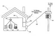
- FIG. 1is a block diagram of a typical electrical power system-based communication system
- FIG. 2is a block diagram of a communication system using an electric power system to transfer data
- FIG. 3provides a basic block diagram of the components necessary to connect the medium voltage portion of the system with the low voltage portion.
- FIG. 4illustrates a prior art coupling technique
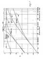
- FIG. 5illustrates a graphical comparative simulation between the coupling technique of FIG. 1 and the coupling technique according to an embodiment of the invention
- FIG. 6illustrates pulse transmission with low capacitance of a prior art lightning arrestor, according to the invention
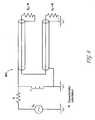
- FIG. 7is a diagram of a coupler technique, according to the invention.
- FIG. 8is an equivalent circuit coupler technique of FIG. 4 , according to the invention.
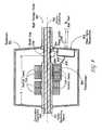
- FIG. 9illustrates a coupler, according to the invention.
- FIG. 10illustrates reception of bipolar pulses, according to the invention.
- FIG. 11is a flow diagram of a method for transporting a signal over a power line, according to the invention.
- FIG. 1is a block diagram of a typical electrical power system-based communication system 100 . It should be appreciated that system 100 may include numerous other components, well known to those skilled in the art. However, the components depicted in system 100 and shown for the purposes of clarity and brevity, while providing a proper context for the invention.
- a power company 120distributes power over its network to a power transformer 102 .
- Power transformer 102can serve several end users.
- Power transformer 102provides stepped-down voltage to an electric power meter 104 , which may be located with the end user.
- Power meter 102is coupled to various appliances 106 , 108 , and 110 , which may represent any type of residential, commercial or industrial electrical equipment.
- a telephone company 112provides telecommunication wiring over its network directly to the end user. The telecommunication wiring may be in communication with various devices, including a telephone 114 , a facsimile machine 116 , and/or a computing device 118 . Therefore, FIG. 1 provides an overview of the two separate systems or networks (i.e., telecommunications system and power system) that serve to a residential, commercial or industrial end user.
- FIG. 2is a block diagram of a communication system using an electric power system to transfer data.
- the communication systemmay include numerous other components, well known to those skilled in the art, the system depicted in FIG. 2 is shown for the purposes of clarity and brevity, while providing a proper context for the invention.
- power company 120delivers electrical power (typically in the several kilovolt range) to a power transformer 102 .
- Power transformer 102steps the voltage level down (e.g., to approximately 110 volts or 120 volts) as required and provides power over power line 202 to a power meter 104 .
- power transformer 102provides electrical isolation characteristics.
- Poweris provided from power meter 104 to the residential, commercial or industrial end user via internal power wiring 208 .
- a power line interface device (PLID) 210is in communication with internal power wiring 208 .
- PIDpower line interface device
- internal power wiring 208 for a home or businesstypically supports data rates of up to 100 kilobits per second with 1 ⁇ 9 bit error rate (BER).
- PLID 210provides an interface for plain old telephone service (POTS), and data through for example a RS-232 port or Ethernet connection. Therefore, an end user may use PLID 210 to communicate data over power line 202 , via internal power wiring 208 , using telephone 114 , facsimile machine 116 and/or computer 118 , for example. Although not shown in FIG. 2 , it should be appreciated that a user can have multiple PLID's within any particular installation.
- POTSplain old telephone service
- FIG. 3provides a basic block diagram of the components necessary to connect the medium voltage portion of the system with the low voltage portion.
- a series of power transformers 303 - 306connect various end users to a point of presence 301 via an aggregation point (AP) 302 .
- AP 302communications to centralized servers (e.g., the Internet) via a Point of Presence 301 (POP).
- POP 301may be a computing device capable of communicating with a centralized server on the Internet, for example.
- the connection between POP 301 and AP 302can be any type of communication media including fiber, copper or a wireless link.
- Each power transformer 303 - 306has an associated Power Line Bridge 307 - 310 (PLB).
- PLBs 307 - 310provide an interface between the medium voltage on the primary side of the transformer with the low voltage on the secondary side of the transformer.
- PLBs 307 - 310communicate with their respective PLIDs (e.g., PLID 210 and PLB 310 ) located on the low voltage system.
- PLBs 307 - 310employ MV couplers that prevent the medium voltage from passing to the low voltage side of the system via PLB's 307 - 310 , while still allowing communication signals to be transported between the low voltage and medium voltage systems.
- the medium voltage couplerstherefore provide the necessary isolation traditionally provided by power transformers 303 - 306 .
- the inventionis directed at a novel technique for transporting signals between the medium voltage system and the end users.
- FIG. 4is a circuit diagram of a prior art coupling system 400 .
- a high-voltage cable 315is connected to a lightning arrester 402 .
- the term “high-voltage”will be used throughout to describe voltage levels on an electric power system that are higher than typically provided to the end user.
- the term “low-voltage”will be used throughout to describe voltage levels on an electric power system that are provided to the end user.
- Lightning arrester 402is connected to a ground potential 407 by means of a grounding rod 403 .
- the connection between high-voltage cable 315 and ground potential 407has a certain inductance value that may be increased by placing a ferrite core 404 around grounding rod 403 .
- lightning arrester 402typically has a capacitance value in a range of 1 to 170 picofarads (pf) (as will be discussed with reference to FIG. 5 ).
- a transformer device 406is connected in parallel with grounding rod 403 and across ferrite core 404 . Transformer device 406 provides acts to communicate a data signal from high-voltage cable 315 to and from transceiver 405 , while providing the necessary isolation from the high voltage carried by high-voltage cable 315 .
- Transceiver unit 405takes the data signal provided via transformer 406 and transmits and receives data signals from an end user (not shown) or a data server (not shown).
- FIG. 4suffers from many inherent problems.
- a lightning arrester devicemust be installed on both ends of high-voltage cable 315 , thus adversely affecting the real and reactive power components provided by high-voltage cable 315 .
- the capacitive value of the lightning arrestermust be close to the high end of the available range (e.g., 170 pf) rather than to the low end of the range (e.g., 1 pf) so as to ensure that a sufficient signal over a wide frequency band is provided to transceiver 405 (as discussed further with reference to FIG. 5 ).
- system 400represents a dual-pole RLC circuit, and thus exhibits significant signal degradation over each frequency interval, a large as compared to a signal pole circuit.
- FIG. 5provides the graphical results of SPICE (Simulation Program With Integrated Circuit Emphasis) simulation of system 100 .
- FIG. 5illustrates the limitations of the signal in the frequency domain in the prior art, as compared to the invention.
- FIG. 5illustrates the attenuation (dB) of a signal over a range of frequencies (Hz) received by transceiver 106 for various capacitive and resistive values that may be provided in system 100 , and therefore further illustrates the above-mentioned limitations in the prior art.
- a signal source with a 50 ohm internal resistanceis provided on the high-voltage cable 315 .
- the inductive value for system 100is set at 10 microhenries.
- Graphical line 501illustrates a capacitive value of 1 pf and a resistive value of 100 ohms.
- Graphical line 502illustrates a capacitive value of 1 pf and a resistive value of 1 kiloohm.
- Graphical line 503illustrates a capacitive value of 170 pf and a resistive value of 100 ohms.
- Graphical line 504illustrates a capacitive value of 100 pf and a resistive value of 1 kiloohm.
- graphical line 505illustrates the attenuation for frequencies passed by the techniques of the invention. Graphical line 505 is depicted in FIG. 5 for the purpose of comparison with lines 501 - 504 .
- graphical line 505permits a wider range of frequencies to pass with less attenuation than graphical lines 501 - 504 , over most of the frequencies.
- each of lines 501 - 502indicate that system 100 causes a large attenuation for frequencies that are less than 600 kHz.
- lines 501 - 502causes a greater attenuation than line 505 over the entire range of frequencies depicted in FIG. 5 .
- system 100uses capacitive values at the lower end of the available range (e.g., 1 pf)
- attenuation of the signalsis great and therefore undesirable.
- line 503 - 504where the capacitive values are on the higher end of the range (e.g., 100 pf)
- attenuationis great.
- line 504( 170 pf and 1 kiloohm) provides less attenuation over a narrow range of frequencies
- line 505may be more beneficial for providing a better or equal attenuation over a wider range of frequencies. Accordingly, neither high nor low values for system 100 will ensure a uniform coupling in a wide frequency band. Also, as depicted with line 504 at a frequency of 4 MHz, system 100 may exhibit resonant behavior at high coupling coefficients. These variations in the frequency domain can distort the data signal, or at least require additional design considerations for system 100 including transceiver 405 , for example.
- lines 501 - 504with line 505 indicates that the dual-pole nature of the prior art circuit leads to a faster rate of coupling decay at lower frequencies. For example, as shown in FIG. 5 , from 100 kHz to approximately 2 MHz, lines 501 - 504 exhibit a 12 dB/octave. This is to be distinguished from the 6 dB/octave decay in line 505 representing the invention's single-pole characteristics.
- FIG. 6further illustrates the inadequacy of prior art system 100 by providing a graphical representation of one of prior art lines 501 - 504 in the time domain (as compared to FIG. 5 's depiction in the frequency domain).
- FIG. 6provides a depiction of the distortion that system 100 causes to a rectangular pulse with a 1 volt and a 100 nanosecond (ns) duration.
- nsnanosecond
- FIG. 6even with a generous grounding-rod inductance of 1 microfarad ( ⁇ F); the inputted rectangular pulse is significantly distorted.
- the inventionprovides much less attenuation of the inputted signal.
- any surge appearing on high-voltage line 315likely will damage transceiver 105 .
- FIG. 7is a diagram of a coupler technique, according to the invention.
- FIG. 7provides a conceptual diagram of a method for coupling a data transceiver to an electrical power line.
- High-voltage cable 315is shown in FIG. 7 .
- High-voltage cablemay be a commercially available distribution cable, for example a 15 kV underground feeder available from Okonite, model Okoguard URO.
- High-voltage cable 315has a center conductor 703 .
- Center conductor 703typically is a stranded aluminum conductor with a rating capable of carrying current at medium voltage levels.
- Center conductor 703has one or more insulative covers (not shown). The insulation on center conductor 703 is surrounded by a concentric conductor 704 .
- Concentric conductor 704typically is found on underground distribution feeders, but also may be found on certain overhead distribution feeders.
- Concentric conductor 704typically does not carry high voltage, but acts as a shield to reduce the inductance caused by center conductor 703 . Concentric conductor 704 also may act to carry the neutral current back to the power source. Concentric conductor 704 is surrounded by an outer insulating sleeve (not shown). The outer insulating sleeve provides protection and insulative properties to high-voltage cable 315 . High-voltage cable 315 is assumed to be AC-terminated at its ends.
- high-voltage cable 315may be modified to facilitate the use of high-voltage cable 315 in carrying desired data signals.
- a shield gap 706has been cut in concentric conductor 704 around the entire periphery of high-voltage cable 315 .
- Shield gap 706effectively divides concentric conductor 704 into two parts.
- a transceiver 707is in communication with high-voltage cable 315 by a connection to concentric conductor 704 .
- transceiver 707may be a fiber-optic transceiver (as will be discussed further with reference to FIG. 6 ), capable of receiving and transmitting any type of data signal (e.g., radio frequency signals).
- Subscriber sideand “transformer side” will be used throughout to describe the two sides of high-voltage cable 315 relative to shield gap 706 .
- Subscriber sidewill be used to describe the portion of high-voltage cable 315 to which transceiver 707 is coupled. This is consistent with the fact that the subscriber (i.e., end user) is in communication with transceiver 707 .
- Transformer sidewill be used to describe the portion of high-voltage cable 315 to which transceiver 707 is not coupled. This is consistent with the fact that the pole-top or pad-mount transformer is coupled to the transformer side of high-voltage cable 315 .
- the ground connection 107(along with other ground connections along the length of high-voltage cable 315 is provided at a distance 1 from the subscribe side of shield gap 706 .
- High-voltage cable 315has an inductance that depends on the distance 1 from ground, as well as other characteristics of high-voltage cable 315 (e.g., diameter and distance from ground plane).
- Inductance Lperforms a function similar to the inductance of grounding rod 103 described with reference to FIG. 1 .
- inductance Lmay be increased.
- Increasing inductance Lmay be accomplished by placing additional ferrite cores 708 along the length of high-voltage cable 10 .
- a more complete discussion of the placement of the grounding and inductive meansis beyond the scope of the invention.
- the length distance 1should not be significantly longer than a quarter-wavelength at the highest frequency in the transmission band, so as to prevent any resonant behavior that may increase transmission attenuation. Because the input reactance of the high-voltage cable 315 is proportional to its characteristic impedance, increasing the impedance as much as practically possible ensures low attenuation at the low end of the frequency band. This is further ensured by using a relatively high ratio of the outer and inner diameters of high-voltage cable 315 , as well as by using ferrite cores 708 with high relative permeance (e.g., 8 maxwell/gilbert).
- FIG. 8is a circuit diagram 800 representing the salient properties of the components depicted in FIG. 7 .
- the subscriber side and transformer side of high-voltage cable 315may be represented by two separate impedances, R S and R T , respectively, connected in series to each other.
- inductance Lwhich represents the inductance of high-voltage cable 315 from ground shield 706 to ground 107 as discussed with reference to FIG. 7 , is placed in parallel to impedances R S and R T .
- inductance L depicted in FIG. 8may be represented in practice by an input impedance of a short piece of a shortened coaxial line.
- the signal sourcemay be represented by a voltage V S and by an internal resistance R.
- signal sourcemay be replaced by a signal load that receives a signal.
- each sidecarries half of the signal power.
- this techniqueprovides an approximately 6 dB loss per octave, as compared to the 12 db per loss octave typically found in the prior art.
- circuit 800has a single-pole characteristic at lower frequencies, because the frequency response of circuit 800 is defined by the “RL” circuit defined by R and L.
- Optimizing the internal resistance of the source (or the load)also may be considered.
- the sources internal resistancewith the resistance of the line to which it is connected (i.e., 2W).
- the two of the couplersare intended to be included between the terminations at the two ends of the line, and if the RF attenuation of the cable in the transmission band is low, it may be desirable to adopt a reasonable trade off.
- the reflectionscan be brought to a more desirable level.
- RW
- FIG. 9provides an example of a coupler, according to the invention.
- FIG. 9illustrates the physical configuration of the inventive method, it will be appreciated that the invention may be implemented in any number of configurations (e.g., using various types of enclosures and/or various types of grounding techniques). Accordingly, it should be appreciated that FIG. 9 provides just one example of a coupler contemplated by the invention.
- high-voltage cable 315is depicted having center conductor 703 , concentric conductor 704 , outer insulating sleeve 915 , and shield gap 706 .
- a metal enclosure 901provides the needed uninterrupted way for the power current flow to back over the interrupted concentric conductor 704 .
- metal enclosure 901also provides the necessary ground connection (described as ground 407 in FIGS. 4 and 7 ), and it forms an outer shield for a piece of shortened coaxial line that may be used to provide inductive shunt impedance (described as L with reference to FIGS. 7 and 8 ).
- High-voltage cable 315also has a series of ferrite cores 708 on the outer side of high-voltage cable 315 .
- Using multiple ferrite coresincreases the impedance of subscriber side of high-voltage cable 315 with the length l (as discussed with reference to FIG. 7 ).
- ferrite coresmay increase the equivalent inductance L of the high-voltage cable 315 , which has the same effect as increasing the impedance.
- Ferrite cores 708also may provide a current transforming function. As shown in FIG. 9 , two of ferrite cores 708 have conductors wound around their perimeter to form a transformer device 902 .
- Transformer 902is coupled to a fiber optic transceiver 903 .
- Fiber optic transceiver 903may be a transmitter/receiver pair commercially available from Microwave Photonic Systems, part number MP-2320/TX (for the transmitter) and part number MP-2320/RX (for the receiver).
- Fiber optic transceiver 903is connected to transformer 902 over lines 908 and 909 .
- transformer 902acts to induce an AC current from the high voltage carried by center conductor 703 .
- the induced alternating currentis provided to fiber optic transceiver 903 via lines 908 and 909 .
- fiber optic transceiver 903may have circuitry capable of rectifying the AC voltage provided by transformer 902 to a DC voltage.
- the DC voltagemay be in a range (e.g., 12 volts) capable of powering the transmitter/receiver pair in fiber optic transceiver 903 , so as to transmit and receive data to the end user over fiber links 906 .
- fiber optic transceiver 903may have a filtering device (not shown) coupled to lines 908 and 909 so as to pass the AC current in a desired frequency range (e.g., 60 Hz using a low-pass filter).
- the data provided to and received from the end usersis carried back to a central server (not shown) from fiber optic transceiver 903 via data links 904 and 905 .
- Data links 904 and 905are in communication with concentric conductor 704 . Because concentric conductor 704 typically is not used to carry high voltage, but acts as an inductive shield for high-voltage cable 315 , data may be carried to and from the end user via concentric conductor 704 .
- fiber optic transceiver 903may have a filtering device (not shown) coupled to lines 904 and 905 , so as to pass data signals in a desired frequency range (e.g., signals well above 60 Hz using a high-pass filter), while preventing other signals from passing onto fiber optic transceiver 903 (e.g., 60 Hz power).
- a filtering devicenot shown coupled to lines 904 and 905 , so as to pass data signals in a desired frequency range (e.g., signals well above 60 Hz using a high-pass filter), while preventing other signals from passing onto fiber optic transceiver 903 (e.g., 60 Hz power).
- the inventionwas described using a fiber optic-based transceiver. Using a fiber optic transceiver provides the necessary isolation to the end user from the medium or high voltage on center conductor 703 , and therefore ensures the safety of people and equipment. However, it should be appreciated that the invention contemplates the user of other types of transceivers, for example, where such isolation is not required.
- FIG. 10illustrates several received pulse shapes for two successive pulses of opposite polarity.
- FIG. 10provides a graphical representation of the signal strength available with the invention. Pulses correspond to the range of characteristic impedances of the stub line from 600 Ohms to 2000 Ohms so as to provide minimum intersymbol interference.
- the transmitted pulseshave amplitudes of ⁇ 1V and a pulse duration of 7 ns each, with the delay between them equal to 25 ns.
- the inventionprovides less attenuation of the inputted signal, and over a smaller time interval.
- FIG. 11is a flow diagram of a method for transporting a signal over a power line.
- an AC current voltageis induced from the power line.
- the induced AC voltageis filtered, for example, by a low-pass filter.
- a transceiver deviceis powered by the induced AC voltage.
- the signalis filtered, for example, by a high-pass filter.
- the signalis communicated between the transceiver device and the power line.
- the signalis transmitted to an end user via the transceiver device.
- the signalis received from an end user via the transceiver device.
- the inventionis directed to a method and a device for transporting a signal over a power line.
- the inventionoccasionally was described in the context underground distribution systems, but is not so limited to, regardless of any specific description in the drawing or examples set forth herein.
- the inventionmay be applied to overhead networks.
- the inventionwas described in the context of medium voltage cables, but also includes high voltage cables. It will be understood that the invention is not limited to use of any of the particular components or devices herein. Indeed, this invention can be used in any application that requires the testing of a communications system. Further, the system disclosed in the invention can be used with the method of the invention or a variety of other applications.
Landscapes
- Engineering & Computer Science (AREA)
- Power Engineering (AREA)
- Computer Networks & Wireless Communication (AREA)
- Signal Processing (AREA)
- Cable Transmission Systems, Equalization Of Radio And Reduction Of Echo (AREA)
Abstract
Description
K=(3W−W)/(W+3W)=½ (1)
K=(2W−W)/(W+2W)=⅓ (2)
It should be appreciated that the examples provided by equations (1) and (2) are just one possible configuration, and are not meant to be exclusive. In practice, fore example, a value of K may be chosen with consideration of the attenuation provided by the particular characteristics of high-
Claims (48)
Priority Applications (3)
| Application Number | Priority Date | Filing Date | Title |
|---|---|---|---|
| US09/924,730US6980089B1 (en) | 2000-08-09 | 2001-08-08 | Non-intrusive coupling to shielded power cable |
| US10/947,929US7245201B1 (en) | 2000-08-09 | 2004-09-23 | Power line coupling device and method of using the same |
| US11/265,230US7248148B2 (en) | 2000-08-09 | 2005-11-03 | Power line coupling device and method of using the same |
Applications Claiming Priority (2)
| Application Number | Priority Date | Filing Date | Title |
|---|---|---|---|
| US22403100P | 2000-08-09 | 2000-08-09 | |
| US09/924,730US6980089B1 (en) | 2000-08-09 | 2001-08-08 | Non-intrusive coupling to shielded power cable |
Related Child Applications (1)
| Application Number | Title | Priority Date | Filing Date |
|---|---|---|---|
| US10/947,929Continuation-In-PartUS7245201B1 (en) | 2000-08-09 | 2004-09-23 | Power line coupling device and method of using the same |
Publications (1)
| Publication Number | Publication Date |
|---|---|
| US6980089B1true US6980089B1 (en) | 2005-12-27 |
Family
ID=35482595
Family Applications (1)
| Application Number | Title | Priority Date | Filing Date |
|---|---|---|---|
| US09/924,730Expired - LifetimeUS6980089B1 (en) | 2000-08-09 | 2001-08-08 | Non-intrusive coupling to shielded power cable |
Country Status (1)
| Country | Link |
|---|---|
| US (1) | US6980089B1 (en) |
Cited By (35)
| Publication number | Priority date | Publication date | Assignee | Title |
|---|---|---|---|---|
| US20050077868A1 (en)* | 2004-12-14 | 2005-04-14 | Ambient Corporation | Arrangement of daisy chained inductive couplers for data communication |
| US20050275495A1 (en)* | 2002-06-21 | 2005-12-15 | Pridmore Charles F Jr | Power line coupling device and method of using the same |
| US20060079198A1 (en)* | 2001-02-15 | 2006-04-13 | Sanderson Lelon W | Apparatus, method and system for range extension of a data communication signal on a high voltage cable |
| US20060290476A1 (en)* | 2005-06-28 | 2006-12-28 | International Broadband Electric Communications, Inc. | Improved Coupling of Communications Signals to a Power Line |
| US20060291546A1 (en)* | 2005-06-28 | 2006-12-28 | International Broadband Electric Communications, Inc. | Device and method for enabling communications signals using a medium voltage power line |
| US20070016702A1 (en)* | 2005-07-14 | 2007-01-18 | Quantum Corporation, A Delaware Corporation | Data flow control and bridging architecture enhancing performance of removable data storage systems |
| US20070014529A1 (en)* | 2005-07-15 | 2007-01-18 | International Broadband Electric Communications, Inc. | Improved Coupling of Communications Signals to a Power Line |
| US20070013491A1 (en)* | 2005-07-15 | 2007-01-18 | International Broadband Electric Communications, Inc. | Coupling Communications Signals To Underground Power Lines |
| US7218219B2 (en) | 2001-02-14 | 2007-05-15 | Current Technologies, Llc | Data communication over a power line |
| US7224243B2 (en) | 2002-06-24 | 2007-05-29 | Current Technologies, Llc | Power line coupling device and method of using the same |
| US7245201B1 (en) | 2000-08-09 | 2007-07-17 | Current Technologies, Llc | Power line coupling device and method of using the same |
| US7245472B2 (en) | 2001-05-18 | 2007-07-17 | Curretn Grid, Llc | Medium voltage signal coupling structure for last leg power grid high-speed data network |
| US7248148B2 (en) | 2000-08-09 | 2007-07-24 | Current Technologies, Llc | Power line coupling device and method of using the same |
| US7307512B2 (en) | 2005-04-29 | 2007-12-11 | Current Technologies, Llc | Power line coupling device and method of use |
| US7424031B2 (en) | 1998-07-28 | 2008-09-09 | Serconet, Ltd. | Local area network of serial intelligent cells |
| US7447320B2 (en)* | 2001-02-14 | 2008-11-04 | Gentex Corporation | Vehicle accessory microphone |
| US7633966B2 (en) | 2000-04-19 | 2009-12-15 | Mosaid Technologies Incorporated | Network combining wired and non-wired segments |
| US7656904B2 (en) | 2003-03-13 | 2010-02-02 | Mosaid Technologies Incorporated | Telephone system having multiple distinct sources and accessories therefor |
| US20100067387A1 (en)* | 2008-09-12 | 2010-03-18 | Shuji Tsunoda | Network Capture Method Using a Transformer |
| US7795994B2 (en) | 2007-06-26 | 2010-09-14 | Current Technologies, Llc | Power line coupling device and method |
| US7808128B1 (en) | 2004-11-12 | 2010-10-05 | Dgi Creations, Llc | Remote monitoring of control decisions for network protectors |
| US7813451B2 (en) | 2006-01-11 | 2010-10-12 | Mobileaccess Networks Ltd. | Apparatus and method for frequency shifting of a wireless signal and systems using frequency shifting |
| US20100289629A1 (en)* | 2008-10-28 | 2010-11-18 | Cooper Technologies Company | Load Control Device with Two-Way Communication Capabilities |
| US7876174B2 (en) | 2007-06-26 | 2011-01-25 | Current Technologies, Llc | Power line coupling device and method |
| US7893685B2 (en) | 2006-08-28 | 2011-02-22 | Acterna Llc | RF meter with input noise suppression |
| US20110075646A1 (en)* | 2003-05-20 | 2011-03-31 | Belair Networks Inc. | Wireless system for communication |
| US8035507B2 (en) | 2008-10-28 | 2011-10-11 | Cooper Technologies Company | Method and apparatus for stimulating power line carrier injection with reactive oscillation |
| US8175649B2 (en) | 2008-06-20 | 2012-05-08 | Corning Mobileaccess Ltd | Method and system for real time control of an active antenna over a distributed antenna system |
| US8325693B2 (en) | 2004-05-06 | 2012-12-04 | Corning Mobileaccess Ltd | System and method for carrying a wireless based signal over wiring |
| US20130214736A1 (en)* | 2012-02-22 | 2013-08-22 | Electric Power Research Institute, Inc. | Apparatus and method for harvesting power from an overhead transmission conductor |
| US8594133B2 (en) | 2007-10-22 | 2013-11-26 | Corning Mobileaccess Ltd. | Communication system using low bandwidth wires |
| US8860353B1 (en) | 2011-04-22 | 2014-10-14 | Dgi Creations, Llc | Protection for a network protector close motor |
| US8897215B2 (en) | 2009-02-08 | 2014-11-25 | Corning Optical Communications Wireless Ltd | Communication system using cables carrying ethernet signals |
| US9184960B1 (en) | 2014-09-25 | 2015-11-10 | Corning Optical Communications Wireless Ltd | Frequency shifting a communications signal(s) in a multi-frequency distributed antenna system (DAS) to avoid or reduce frequency interference |
| US9338823B2 (en) | 2012-03-23 | 2016-05-10 | Corning Optical Communications Wireless Ltd | Radio-frequency integrated circuit (RFIC) chip(s) for providing distributed antenna system functionalities, and related components, systems, and methods |
Citations (260)
| Publication number | Priority date | Publication date | Assignee | Title |
|---|---|---|---|---|
| US1547242A (en) | 1924-04-29 | 1925-07-28 | American Telephone & Telegraph | Carrier transmission over power circuits |
| US2298435A (en) | 1940-11-26 | 1942-10-13 | Rca Corp | Radio relaying |
| US2577731A (en) | 1942-02-20 | 1951-12-11 | Int Standard Electric Corp | High-frequency traffic system over power supply lines |
| US3369078A (en) | 1965-06-28 | 1968-02-13 | Charles R. Stradley | System for transmitting stereophonic signals over electric power lines |
| US3445814A (en) | 1963-03-25 | 1969-05-20 | Electrometre Sa | System for interrogating remote stations via power lines of an electrical distribution network |
| US3605009A (en)* | 1970-05-06 | 1971-09-14 | Deltaray Corp | Stabilized power supply |
| US3641536A (en) | 1970-04-14 | 1972-02-08 | Veeder Industries Inc | Gasoline pump multiplexer system for remote indicators for self-service gasoline pumps |
| US3656112A (en) | 1969-03-14 | 1972-04-11 | Constellation Science And Tech | Utility meter remote automatic reading system |
| US3696383A (en) | 1970-01-17 | 1972-10-03 | Tokyo Electric Power Co | Information transmission system for metered magnitudes |
| US3702460A (en) | 1971-11-30 | 1972-11-07 | John B Blose | Communications system for electric power utility |
| US3810096A (en) | 1972-09-14 | 1974-05-07 | Integrated Syst Co | Method and system for transmitting data and indicating room status |
| US3846638A (en) | 1972-10-02 | 1974-11-05 | Gen Electric | Improved coupling arrangement for power line carrier systems |
| US3895370A (en) | 1972-07-04 | 1975-07-15 | Sits Soc It Telecom Siemens | High-frequency communication system using A-C utility lines |
| US3911415A (en) | 1973-12-18 | 1975-10-07 | Westinghouse Electric Corp | Distribution network power line carrier communication system |
| US3942168A (en) | 1975-01-31 | 1976-03-02 | Westinghouse Electric Corporation | Distribution network power line communication system |
| US3942170A (en) | 1975-01-31 | 1976-03-02 | Westinghouse Electric Corporation | Distribution network powerline carrier communication system |
| US3962547A (en) | 1975-05-27 | 1976-06-08 | Westinghouse Electric Corporation | Repeater coupler for power line communication systems |
| US3964048A (en) | 1974-01-28 | 1976-06-15 | General Public Utilities Corporation | Communicating over power network within a building or other user location |
| US3967264A (en) | 1975-01-31 | 1976-06-29 | Westinghouse Electric Corporation | Distribution network power line communication system including addressable interrogation and response repeater |
| US3973087A (en) | 1974-12-05 | 1976-08-03 | General Electric Company | Signal repeater for power line access data system |
| US3973240A (en) | 1974-12-05 | 1976-08-03 | General Electric Company | Power line access data system |
| US4004110A (en) | 1975-10-07 | 1977-01-18 | Westinghouse Electric Corporation | Power supply for power line carrier communication systems |
| US4004257A (en) | 1975-07-09 | 1977-01-18 | Vitek Electronics, Inc. | Transmission line filter |
| US4012733A (en) | 1975-10-16 | 1977-03-15 | Westinghouse Electric Corporation | Distribution power line communication system including a messenger wire communications link |
| US4016429A (en) | 1976-01-16 | 1977-04-05 | Westinghouse Electric Corporation | Power line carrier communication system for signaling customer locations through ground wire conductors |
| FR2326087A1 (en) | 1975-09-25 | 1977-04-22 | Zellweger Uster Ag | METHOD AND DEVICE FOR BILATERAL PULSE TRANSMISSION, ESPECIALLY FOR THE MONITORING OF TEXTILE MACHINES |
| US4053876A (en) | 1976-04-08 | 1977-10-11 | Sidney Hoffman | Alarm system for warning of unbalance or failure of one or more phases of a multi-phase high-current load |
| US4057793A (en) | 1975-10-28 | 1977-11-08 | Johnson Raymond E | Current carrier communication system |
| US4060735A (en) | 1976-07-12 | 1977-11-29 | Johnson Controls, Inc. | Control system employing a programmable multiple channel controller for transmitting control signals over electrical power lines |
| US4070572A (en) | 1976-12-27 | 1978-01-24 | General Electric Company | Linear signal isolator and calibration circuit for electronic current transformer |
| US4119948A (en) | 1976-04-29 | 1978-10-10 | Ernest Michael Ward | Remote meter reading system |
| US4142178A (en) | 1977-04-25 | 1979-02-27 | Westinghouse Electric Corp. | High voltage signal coupler for a distribution network power line carrier communication system |
| GB1548652A (en) | 1974-02-08 | 1979-07-18 | Ruddy J M | Telephone extension system utilizing power line carrier signals |
| US4188619A (en) | 1978-08-17 | 1980-02-12 | Rockwell International Corporation | Transformer arrangement for coupling a communication signal to a three-phase power line |
| US4239940A (en) | 1978-12-26 | 1980-12-16 | Bertrand Dorfman | Carrier current communications system |
| US4250489A (en) | 1978-10-31 | 1981-02-10 | Westinghouse Electric Corp. | Distribution network communication system having branch connected repeaters |
| US4254402A (en) | 1979-08-17 | 1981-03-03 | Rockwell International Corporation | Transformer arrangement for coupling a communication signal to a three-phase power line |
| US4263549A (en) | 1979-10-12 | 1981-04-21 | Corcom, Inc. | Apparatus for determining differential mode and common mode noise |
| US4268818A (en) | 1978-03-20 | 1981-05-19 | Murray W. Davis | Real-time parameter sensor-transmitter |
| US4323882A (en) | 1980-06-02 | 1982-04-06 | General Electric Company | Method of, and apparatus for, inserting carrier frequency signal information onto distribution transformer primary winding |
| US4357598A (en) | 1981-04-09 | 1982-11-02 | Westinghouse Electric Corp. | Three-phase power distribution network communication system |
| US4359644A (en) | 1978-06-09 | 1982-11-16 | The Electricity Trust Of South Australia | Load shedding control means |
| US4367522A (en) | 1980-03-28 | 1983-01-04 | Siemens Aktiengesellschaft | Three-phase inverter arrangement |
| GB2101857A (en) | 1981-05-08 | 1983-01-19 | Atomic Energy Authority Uk | A communications system |
| US4383243A (en) | 1978-06-08 | 1983-05-10 | Siemens Aktiengesellschaft | Powerline carrier control installation |
| US4386436A (en) | 1981-02-27 | 1983-05-31 | Rca Corporation | Television remote control system for selectively controlling external apparatus through the AC power line |
| US4408186A (en) | 1981-02-04 | 1983-10-04 | General Electric Co. | Power line communication over ground and neutral conductors of plural residential branch circuits |
| US4409542A (en) | 1980-05-27 | 1983-10-11 | Siemens Aktiengesellschaft | Monitoring system for an LC filter circuit in an AC power network |
| US4413250A (en) | 1981-09-03 | 1983-11-01 | Beckman Instruments, Inc. | Digital communication system for remote instruments |
| US4419621A (en) | 1980-05-27 | 1983-12-06 | Siemens Aktiengesellschaft | Monitoring system for the capacitor batteries of a three-phase filter circuit |
| US4433284A (en) | 1982-04-07 | 1984-02-21 | Rockwell International Corporation | Power line communications bypass around delta-wye transformer |
| US4442492A (en) | 1979-08-21 | 1984-04-10 | Karlsson Bjoern G E | Device for central reading and registration of customers' power consumption |
| WO1984001481A1 (en) | 1982-09-30 | 1984-04-12 | Astech Inc | Telephone extension system |
| US4457014A (en) | 1980-10-03 | 1984-06-26 | Metme Communications | Signal transfer and system utilizing transmission lines |
| US4468792A (en) | 1981-09-14 | 1984-08-28 | General Electric Company | Method and apparatus for data transmission using chirped frequency-shift-keying modulation |
| US4471399A (en) | 1982-03-11 | 1984-09-11 | Westinghouse Electric Corp. | Power-line baseband communication system |
| US4473817A (en) | 1982-04-13 | 1984-09-25 | Rockwell International Corporation | Coupling power line communications signals around distribution transformers |
| US4473816A (en) | 1982-04-13 | 1984-09-25 | Rockwell International Corporation | Communications signal bypass around power line transformer |
| US4475209A (en) | 1982-04-23 | 1984-10-02 | Westinghouse Electric Corp. | Regenerator for an intrabundle power-line communication system |
| US4479033A (en) | 1982-03-29 | 1984-10-23 | Astech, Inc. | Telephone extension system utilizing power line carrier signals |
| US4481501A (en) | 1978-08-17 | 1984-11-06 | Rockwell International Corporation | Transformer arrangement for coupling a communication signal to a three-phase power line |
| US4495386A (en) | 1982-03-29 | 1985-01-22 | Astech, Inc. | Telephone extension system utilizing power line carrier signals |
| US4504705A (en) | 1982-01-18 | 1985-03-12 | Lgz Landis & Gyr Zug Ag | Receiving arrangements for audio frequency signals |
| US4517548A (en) | 1982-12-20 | 1985-05-14 | Sharp Kabushiki Kaisha | Transmitter/receiver circuit for signal transmission over power wiring |
| EP0141673A2 (en) | 1983-11-07 | 1985-05-15 | Emlux Limited | Filtering electrical signals |
| US4569045A (en) | 1983-06-06 | 1986-02-04 | Eaton Corp. | 3-Wire multiplexer |
| US4599598A (en) | 1981-09-14 | 1986-07-08 | Matsushita Electric Works, Ltd. | Data transmission system utilizing power line |
| US4636771A (en) | 1984-12-10 | 1987-01-13 | Westinghouse Electric Corp. | Power line communications terminal and interface circuit associated therewith |
| US4638298A (en) | 1985-07-16 | 1987-01-20 | Telautograph Corporation | Communication system having message repeating terminals |
| US4642607A (en) | 1985-08-06 | 1987-02-10 | National Semiconductor Corporation | Power line carrier communications system transformer bridge |
| US4644321A (en) | 1984-10-22 | 1987-02-17 | Westinghouse Electric Corp. | Wireless power line communication apparatus |
| US4652855A (en) | 1984-12-05 | 1987-03-24 | Westinghouse Electric Corp. | Portable remote meter reading apparatus |
| US4668934A (en) | 1984-10-22 | 1987-05-26 | Westinghouse Electric Corp. | Receiver apparatus for three-phase power line carrier communications |
| US4675648A (en)* | 1984-04-17 | 1987-06-23 | Honeywell Inc. | Passive signal coupler between power distribution systems for the transmission of data signals over the power lines |
| US4683450A (en)* | 1982-07-01 | 1987-07-28 | Feller Ag | Line with distributed low-pass filter section wherein spurious signals are attenuated |
| US4686641A (en) | 1985-03-18 | 1987-08-11 | Detroit Edison Company | Static programmable powerline carrier channel test structure and method |
| US4686382A (en) | 1985-08-14 | 1987-08-11 | Westinghouse Electric Corp. | Switch bypass circuit for power line communication systems |
| US4697166A (en)* | 1986-08-11 | 1987-09-29 | Nippon Colin Co., Ltd. | Method and apparatus for coupling transceiver to power line carrier system |
| US4701945A (en) | 1984-10-09 | 1987-10-20 | Pedigo Michael K | Carrier current transceiver |
| US4724381A (en) | 1986-02-03 | 1988-02-09 | Niagara Mohawk Power Corporation | RF antenna for transmission line sensor |
| US4745391A (en) | 1987-02-26 | 1988-05-17 | General Electric Company | Method of, and apparatus for, information communication via a power line conductor |
| US4746897A (en) | 1984-01-30 | 1988-05-24 | Westinghouse Electric Corp. | Apparatus for transmitting and receiving a power line |
| US4749992A (en) | 1986-07-03 | 1988-06-07 | Total Energy Management Consultants Corp. (Temco) | Utility monitoring and control system |
| US4766414A (en) | 1986-06-17 | 1988-08-23 | Westinghouse Electric Corp. | Power line communication interference preventing circuit |
| US4772870A (en) | 1986-11-20 | 1988-09-20 | Reyes Ronald R | Power line communication system |
| US4785195A (en) | 1987-06-01 | 1988-11-15 | University Of Tennessee Research Corporation | Power line communication |
| US4800363A (en) | 1986-01-15 | 1989-01-24 | Bbc Brown, Boveri & Company, Limited | Method for data transmission via an electric distribution system and transmission system for carrying out the method |
| US4835517A (en) | 1984-01-26 | 1989-05-30 | The University Of British Columbia | Modem for pseudo noise communication on A.C. lines |
| US4890089A (en) | 1988-11-25 | 1989-12-26 | Westinghouse Electric Corp. | Distribution of line carrier communications |
| US4903006A (en) | 1989-02-16 | 1990-02-20 | Thermo King Corporation | Power line communication system |
| US4904996A (en) | 1988-01-19 | 1990-02-27 | Fernandes Roosevelt A | Line-mounted, movable, power line monitoring system |
| US4912553A (en) | 1986-03-28 | 1990-03-27 | Pal Theodore L | Wideband video system for single power line communications |
| US4962496A (en) | 1988-10-20 | 1990-10-09 | Abb Power T & D Company Inc. | Transmission of data via power lines |
| US4973940A (en) | 1987-07-08 | 1990-11-27 | Colin Electronics Co., Ltd. | Optimum impedance system for coupling transceiver to power line carrier network |
| US4979183A (en) | 1989-03-23 | 1990-12-18 | Echelon Systems Corporation | Transceiver employing direct sequence spread spectrum techniques |
| WO1990013950A3 (en) | 1989-04-28 | 1991-04-04 | Karoly Charles Abraham | Power-line communication apparatus |
| US5006846A (en) | 1987-11-12 | 1991-04-09 | Granville J Michael | Power transmission line monitoring system |
| US5066939A (en) | 1989-10-04 | 1991-11-19 | Mansfield Jr Amos R | Method and means of operating a power line carrier communication system |
| US5068890A (en) | 1986-10-22 | 1991-11-26 | Nilssen Ole K | Combined signal and electrical power distribution system |
| US5132992A (en) | 1991-01-07 | 1992-07-21 | Paul Yurt | Audio and video transmission and receiving system |
| US5148144A (en)* | 1991-03-28 | 1992-09-15 | Echelon Systems Corporation | Data communication network providing power and message information |
| US5151838A (en) | 1989-09-20 | 1992-09-29 | Dockery Gregory A | Video multiplying system |
| WO1992016920A1 (en) | 1991-03-16 | 1992-10-01 | Gjd Manufacturing Limited | Signalling system and method |
| US5185591A (en) | 1991-07-12 | 1993-02-09 | Abb Power T&D Co., Inc. | Power distribution line communication system for and method of reducing effects of signal cancellation |
| US5191467A (en) | 1991-07-24 | 1993-03-02 | Kaptron, Inc. | Fiber optic isolater and amplifier |
| WO1993007693A1 (en) | 1991-10-07 | 1993-04-15 | Phonex Corporation | Multiple access telephone extension systems and methods |
| US5210519A (en) | 1990-06-22 | 1993-05-11 | British Aerospace Public Limited Company | Digital data transmission |
| US5257006A (en) | 1990-09-21 | 1993-10-26 | Echelon Corporation | Method and apparatus for power line communications |
| US5264823A (en) | 1990-09-28 | 1993-11-23 | Motorola Lighting, Inc. | Power line communication system |
| US5272462A (en) | 1991-06-03 | 1993-12-21 | Merlin Gerin | Remote transmission device by on-line carrier currents designed for control and monitoring of an electrical power distribution system, notably medium voltage |
| EP0581351A1 (en) | 1992-07-24 | 1994-02-02 | ITALTEL SOCIETA ITALIANA TELECOMUNICAZIONI s.p.a. | Transceiver for the exchange of informations along lines for the transport of electric power |
| US5301208A (en) | 1992-02-25 | 1994-04-05 | The United States Of America As Represented By The Secretary Of The Air Force | Transformer bus coupler |
| US5341265A (en) | 1990-05-30 | 1994-08-23 | Kearney National, Inc. | Method and apparatus for detecting and responding to downed conductors |
| US5351272A (en) | 1992-05-18 | 1994-09-27 | Abraham Karoly C | Communications apparatus and method for transmitting and receiving multiple modulated signals over electrical lines |
| US5355109A (en) | 1992-02-03 | 1994-10-11 | Kitagawa Industries Co., Ltd. | Electric noise absorber |
| US5359625A (en) | 1989-08-23 | 1994-10-25 | Intellon Corporation | Spread spectrum communication system particularly-suited for RF network communication |
| US5369356A (en) | 1991-08-30 | 1994-11-29 | Siemens Energy & Automation, Inc. | Distributed current and voltage sampling function for an electric power monitoring unit |
| US5375141A (en) | 1992-06-17 | 1994-12-20 | Ricoh Company, Ltd. | Synchronizing circuit in a spread spectrum communications system |
| EP0632602A2 (en) | 1993-05-31 | 1995-01-04 | Alcatel Standard Electrica, S.A. | Power line communications adapter |
| US5387821A (en)* | 1992-11-12 | 1995-02-07 | Allegro Microsystems, Inc. | Power distribution circuit with power factor correction and independent harmonic current filter |
| US5406249A (en) | 1993-03-09 | 1995-04-11 | Metricom, Inc. | Method and structure for coupling power-line carrier current signals using common-mode coupling |
| US5410720A (en) | 1992-10-28 | 1995-04-25 | Alpha Technologies | Apparatus and methods for generating an AC power signal for cable TV distribution systems |
| US5426360A (en) | 1994-02-17 | 1995-06-20 | Niagara Mohawk Power Corporation | Secondary electrical power line parameter monitoring apparatus and system |
| US5432841A (en) | 1992-07-10 | 1995-07-11 | Rimer; Neil A. | System for locating and communicating with mobile vehicles |
| US5448229A (en) | 1992-12-28 | 1995-09-05 | General Electric Company | Method and apparatus for communicating with a meter register |
| US5461629A (en) | 1992-09-09 | 1995-10-24 | Echelon Corporation | Error correction in a spread spectrum transceiver |
| WO1995029536A1 (en) | 1994-04-21 | 1995-11-02 | Norweb Plc | Hybrid electricity and telecommunications distribution network |
| US5477091A (en) | 1991-11-27 | 1995-12-19 | Merlin Gerin | High quality electrical power distribution system |
| US5481249A (en) | 1992-02-14 | 1996-01-02 | Canon Kabushiki Kaisha | Bidirectional communication apparatus for transmitting/receiving information by wireless communication or through a power line |
| US5485040A (en) | 1991-05-10 | 1996-01-16 | Echelon Corporation | Powerline coupling network |
| US5497142A (en) | 1991-10-17 | 1996-03-05 | Electricite De France | Directional separator-coupler circuit for medium-frequency carrier currents on a low-voltage electrical line |
| GB2293950A (en) | 1994-10-04 | 1996-04-10 | Northern Telecom Ltd | Communications system using power distribution network |
| US5533054A (en) | 1993-07-09 | 1996-07-02 | Technitrol, Inc. | Multi-level data transmitter |
| US5537087A (en) | 1991-08-07 | 1996-07-16 | Mitsubishi Denki Kabushiki Kaisha | Signal discriminator |
| US5559377A (en) | 1989-04-28 | 1996-09-24 | Abraham; Charles | Transformer coupler for communication over various lines |
| US5568185A (en)* | 1993-11-11 | 1996-10-22 | Tasco Electronics Co., Ltd. | Audio communication band image transceiver |
| US5579221A (en) | 1993-12-31 | 1996-11-26 | Samsung Electronics Co., Ltd. | Home automation system having user controlled definition function |
| US5579335A (en) | 1995-09-27 | 1996-11-26 | Echelon Corporation | Split band processing for spread spectrum communications |
| US5592354A (en) | 1991-03-19 | 1997-01-07 | Nocentino, Jr.; Albert | Audio bandwidth interface apparatus for pilot wire relays |
| US5592482A (en) | 1989-04-28 | 1997-01-07 | Abraham; Charles | Video distribution system using in-wall wiring |
| US5598406A (en) | 1992-11-06 | 1997-01-28 | Hewlett-Packard Company | High speed data transfer over twisted pair cabling |
| US5616969A (en)* | 1995-07-11 | 1997-04-01 | Morava; Irena | Power distribution system having substantially zero electromagnetic field radiation |
| US5625863A (en) | 1989-04-28 | 1997-04-29 | Videocom, Inc. | Video distribution system using in-wall wiring |
| US5630204A (en) | 1995-05-01 | 1997-05-13 | Bell Atlantic Network Services, Inc. | Customer premise wireless distribution of broad band signals and two-way communication of control signals over power lines |
| US5640416A (en) | 1995-06-07 | 1997-06-17 | Comsat Corporation | Digital downconverter/despreader for direct sequence spread spectrum communications system |
| US5664002A (en) | 1993-05-28 | 1997-09-02 | U S West, Inc. | Method and apparatus for providing power to a coaxial cable network |
| US5684450A (en) | 1992-10-22 | 1997-11-04 | Norweb Plc | Electricity distribution and/or power transmission network and filter for telecommunication over power lines |
| US5691691A (en)* | 1997-01-06 | 1997-11-25 | Motorola, Inc. | Power-line communication system using pulse transmission on the AC line |
| US5694108A (en) | 1996-05-01 | 1997-12-02 | Abb Power T&D Company Inc. | Apparatus and methods for power network coupling |
| US5705974A (en) | 1995-05-09 | 1998-01-06 | Elcom Technologies Corporation | Power line communications system and coupling circuit for power line communications system |
| WO1998001905A1 (en) | 1996-07-09 | 1998-01-15 | Ambient Corporation | Capacitively coupled bi-directional data and power transmission system |
| US5712614A (en) | 1995-05-09 | 1998-01-27 | Elcom Technologies Corporation | Power line communications system |
| EP0822721A2 (en) | 1996-08-02 | 1998-02-04 | Siemens Aktiengesellschaft | Subscriber terminal connecting system for interactive telecommunication services |
| US5717685A (en) | 1989-04-28 | 1998-02-10 | Abraham; Charles | Transformer coupler for communication over various lines |
| GB2315937A (en) | 1996-08-01 | 1998-02-11 | Northern Telecom Ltd | TDMA power line communication transceiver using amplifier with reverse direction bypass |
| US5726980A (en) | 1995-03-30 | 1998-03-10 | Northern Telecom Limited | Time division duplex communications repeater |
| US5748104A (en) | 1996-07-11 | 1998-05-05 | Qualcomm Incorporated | Wireless remote telemetry system |
| US5748671A (en) | 1995-12-29 | 1998-05-05 | Echelon Corporation | Adaptive reference pattern for spread spectrum detection |
| US5751803A (en) | 1995-11-08 | 1998-05-12 | Shmuel Hershkovit | Telephone line coupler |
| US5770996A (en) | 1996-08-30 | 1998-06-23 | Interactive Technologies, Inc. | Transformer system for power line communications |
| US5774526A (en) | 1995-07-18 | 1998-06-30 | Adaptive Networks, Inc. | Reconfigurable on-demand telephone and data line system |
| US5777769A (en) | 1995-12-28 | 1998-07-07 | Lucent Technologies Inc. | Device and method for providing high speed data transfer through a drop line of a power line carrier communication system |
| US5777545A (en) | 1995-05-09 | 1998-07-07 | Elcom Technologies Corporation | Remote control apparatus for power line communications system |
| US5778116A (en) | 1997-01-23 | 1998-07-07 | Tomich; John L. | Photonic home area network fiber/power insertion apparatus |
| US5777544A (en) | 1997-03-17 | 1998-07-07 | Intellon Corporation | Apparatus and method for controlling data communications having combination of wide and narrow band frequency protocols |
| NZ276741A (en) | 1993-11-24 | 1998-07-28 | Remote Metering Systems Ltd | Power line carrier communication: signal coupling at medium voltages |
| WO1998033258A2 (en) | 1997-01-28 | 1998-07-30 | Northern Telecom Limited | Power line transmission |
| US5796607A (en) | 1994-04-28 | 1998-08-18 | Sgs-Thomson Microelectronics, S.A. | Processors, systems, and methods for improved network communications protocol management |
| US5798913A (en) | 1995-02-16 | 1998-08-25 | U.S. Philips Corporation | Power-supply and communication |
| US5801643A (en)* | 1996-06-20 | 1998-09-01 | Northrop Grumman Corporation | Remote utility meter reading system |
| US5802102A (en) | 1995-05-25 | 1998-09-01 | Golden Bridge Technology, Inc. | Programmable two-part matched filter for spread spectrum |
| US5805053A (en) | 1996-10-21 | 1998-09-08 | Elcom Technologies, Inc. | Appliance adapted for power line communications |
| WO1998040980A1 (en) | 1997-03-14 | 1998-09-17 | Videocom, Inc. | Improved transformer coupler for communication over various electrical power lines |
| US5818127A (en) | 1989-04-28 | 1998-10-06 | Videocom, Inc. | Transmission of FM video signals over various lines |
| US5818821A (en) | 1994-12-30 | 1998-10-06 | Intelogis, Inc. | Universal lan power line carrier repeater system and method |
| US5828293A (en) | 1997-06-10 | 1998-10-27 | Northern Telecom Limited | Data transmission over a power line communications system |
| US5835005A (en) | 1994-07-13 | 1998-11-10 | Omron Corporation | Power-line data transmission method and system utilizing relay stations |
| ES2122920A1 (en) | 1996-12-19 | 1998-12-16 | Blazquez Fernando A Beltran | Digital modulator/demodulator adapted to the HSS (Home System Specification) standard for transmitting data via the electricity network. |
| DE19728270A1 (en) | 1997-07-02 | 1999-01-07 | Goerlitz Computerbau Gmbh | Data transmission system using supply network |
| US5864284A (en) | 1997-03-06 | 1999-01-26 | Sanderson; Lelon Wayne | Apparatus for coupling radio-frequency signals to and from a cable of a power distribution network |
| US5870016A (en) | 1997-02-03 | 1999-02-09 | Eva Cogenics Inc Euaday Division | Power line carrier data transmission systems having signal conditioning for the carrier data signal |
| US5881098A (en) | 1996-02-21 | 1999-03-09 | Industrial Technology Research Institute | Efficient demodulation scheme for DSSS communication |
| US5880677A (en) | 1996-10-15 | 1999-03-09 | Lestician; Guy J. | System for monitoring and controlling electrical consumption, including transceiver communicator control apparatus and alternating current control apparatus |
| US5892430A (en) | 1994-04-25 | 1999-04-06 | Foster-Miller, Inc. | Self-powered powerline sensor |
| US5892758A (en) | 1996-07-11 | 1999-04-06 | Qualcomm Incorporated | Concentrated subscriber wireless remote telemetry system |
| EP0913955A2 (en) | 1994-04-21 | 1999-05-06 | Norweb Plc | Transmission network and filter therefor |
| GB2331683A (en) | 1997-11-24 | 1999-05-26 | Norweb Plc | Coupling telecommunications signal to power cables |
| US5933073A (en) | 1997-07-07 | 1999-08-03 | Abb Power T&D Company Inc. | Apparatus and methods for power network coupling |
| EP0933883A2 (en) | 1998-01-30 | 1999-08-04 | Siemens Aktiengesellschaft | Method and device for the determination of the transferfunction of transmitting media |
| US5937342A (en) | 1997-01-28 | 1999-08-10 | Dynamic Telecommunications, Inc. | Wireless local distribution system using standard power lines |
| US5949327A (en) | 1994-08-26 | 1999-09-07 | Norweb Plc | Coupling of telecommunications signals to a balanced power distribution network |
| GB2335335A (en) | 1998-03-13 | 1999-09-15 | Northern Telecom Ltd | Carrying speech-band signals over power lines |
| US5963585A (en) | 1994-10-17 | 1999-10-05 | P-Com, Inc. | MSK spread-spectrum receiver which allows CDMA operations |
| EP0948143A2 (en) | 1998-04-03 | 1999-10-06 | Abb Research Ltd. | Method and device for signal communication over power lines |
| US5977650A (en) | 1998-03-17 | 1999-11-02 | Northern Telecom Limited | Transmitting communications signals over a power line network |
| US5978371A (en) | 1997-03-31 | 1999-11-02 | Abb Power T&D Company Inc. | Communications module base repeater |
| US5982276A (en) | 1998-05-07 | 1999-11-09 | Media Fusion Corp. | Magnetic field based power transmission line communication method and system |
| WO1999059261A1 (en) | 1998-05-08 | 1999-11-18 | Siemens Aktiengesellschaft | Wide-band communication system |
| EP0959569A1 (en) | 1998-05-11 | 1999-11-24 | Abb Research Ltd. | Method and apparatus for signal coupling in high or middle voltage cable |
| US5994998A (en) | 1997-05-29 | 1999-11-30 | 3Com Corporation | Power transfer apparatus for concurrently transmitting data and power over data wires |
| US5994999A (en) | 1997-07-17 | 1999-11-30 | Gec Alsthom T & D Sa | Low voltage link for transmitting on/off orders |
| US6014386A (en)* | 1989-10-30 | 2000-01-11 | Videocom, Inc. | System and method for high speed communication of video, voice and error-free data over in-wall wiring |
| US6023106A (en) | 1994-12-02 | 2000-02-08 | Abraham; Charles | Power line circuits and adaptors for coupling carrier frequency current signals between power lines |
| US6037857A (en) | 1997-06-06 | 2000-03-14 | Allen-Bradley Company, Llc | Serial data isolator industrial control system providing intrinsically safe operation |
| US6037678A (en) | 1997-10-03 | 2000-03-14 | Northern Telecom Limited | Coupling communications signals to a power line |
| US6040759A (en)* | 1998-02-17 | 2000-03-21 | Sanderson; Lelon Wayne | Communication system for providing broadband data services using a high-voltage cable of a power system |
| GB2341776A (en) | 1998-03-17 | 2000-03-22 | Northern Telecom Ltd | Mains signalling transient suppression |
| GB2342264A (en) | 1998-08-04 | 2000-04-05 | Nor Web Dpl Limited | Signal transmission over power networks |
| WO2000016496A3 (en) | 1998-09-15 | 2000-06-08 | Siemens Ag | Arrangement and method for forming an overall signal, device and method for forming a current signal and a first communication signal, communication system and method for transmitting a first overall signal and a second overall signal |
| EP1011235A2 (en) | 1998-12-15 | 2000-06-21 | Nortel Networks Corporation | Reception of multicarrier signals over power lines |
| EP1014640A2 (en) | 1998-12-22 | 2000-06-28 | Nortel Networks Corporation | Multicarrier transmission on power lines |
| US6091932A (en) | 1995-05-20 | 2000-07-18 | Regiocom Gmbh | Bidirectional point to multipoint network using multicarrier modulation |
| GB2347601A (en) | 1998-09-03 | 2000-09-06 | Nor Web Dpl Limited | Communications apparatus with mains filter |
| US6121765A (en)* | 1995-12-13 | 2000-09-19 | Charlotte A. Andres | Isolated electrical power supply |
| WO2000059076A1 (en) | 1999-03-25 | 2000-10-05 | Nor.Web Dpl Limited | Signal coupler |
| US6130896A (en) | 1997-10-20 | 2000-10-10 | Intel Corporation | Wireless LAN segments with point coordination |
| EP1043866A2 (en) | 1999-04-08 | 2000-10-11 | Siemens Aktiengesellschaft | Arrangement for home area data transmission |
| WO2000060822A1 (en) | 1999-03-31 | 2000-10-12 | Siemens Aktiengesellschaft | Method, use of said method and receiver system for receiving multi-carrier signals presenting several frequency-discrete subcarriers |
| WO2000060701A1 (en) | 1999-04-01 | 2000-10-12 | Nor.Web Dpl Limited | Coupling apparatus and method |
| US6141634A (en) | 1997-11-26 | 2000-10-31 | International Business Machines Corporation | AC power line network simulator |
| US6144292A (en) | 1992-10-22 | 2000-11-07 | Norweb Plc | Powerline communications network employing TDMA, FDMA and/or CDMA |
| US6151480A (en)* | 1997-06-27 | 2000-11-21 | Adc Telecommunications, Inc. | System and method for distributing RF signals over power lines within a substantially closed environment |
| US6151330A (en) | 1996-12-04 | 2000-11-21 | Powercom Control Systems Ltd. | Electric power supply management system |
| US6154488A (en) | 1997-09-23 | 2000-11-28 | Hunt Technologies, Inc. | Low frequency bilateral communication over distributed power lines |
| US6157292A (en) | 1997-12-04 | 2000-12-05 | Digital Security Controls Ltd. | Power distribution grid communication system |
| US6175860B1 (en) | 1997-11-26 | 2001-01-16 | International Business Machines Corporation | Method and apparatus for an automatic multi-rate wireless/wired computer network |
| US6177849B1 (en) | 1998-11-18 | 2001-01-23 | Oneline Ag | Non-saturating, flux cancelling diplex filter for power line communications |
| WO2001008321A1 (en) | 1999-07-22 | 2001-02-01 | Siemens Aktiengesellschaft | Interface circuit for surge impedance |
| EP1075091A1 (en) | 1999-07-22 | 2001-02-07 | Siemens Aktiengesellschaft | Method, circuit and system for operation of a low voltage network for data transmission in an energy distribution |
| US6212658B1 (en) | 1993-09-02 | 2001-04-03 | Sgs-Thomson Microelectronics S.A. | Method for the correction of a message in an installation |
| US6226166B1 (en) | 1997-11-28 | 2001-05-01 | Erico Lighting Technologies Pty Ltd | Transient overvoltage and lightning protection of power connected equipment |
| US6229434B1 (en) | 1999-03-04 | 2001-05-08 | Gentex Corporation | Vehicle communication system |
| US6239722B1 (en) | 1997-10-16 | 2001-05-29 | Cic Global, Llc | System and method for communication between remote locations |
| US6243413B1 (en) | 1998-04-03 | 2001-06-05 | International Business Machines Corporation | Modular home-networking communication system and method using disparate communication channels |
| US6243571B1 (en) | 1998-09-21 | 2001-06-05 | Phonex Corporation | Method and system for distribution of wireless signals for increased wireless coverage using power lines |
| DE10008602A1 (en) | 2000-02-24 | 2001-06-07 | Siemens Ag | Data processing device with power supply and power supply for data processing devices |
| WO2001043305A1 (en) | 1999-12-08 | 2001-06-14 | Ascom Powerline Communications Ag | Coupling device |
| US6255805B1 (en) | 2000-02-04 | 2001-07-03 | Motorola, Inc. | Device for electrical source sharing |
| US6255935B1 (en) | 1998-09-14 | 2001-07-03 | Abb Research Ltd. | Coupling capacitor having an integrated connecting cable |
| WO2001050625A2 (en) | 1999-12-30 | 2001-07-12 | Siemens Aktiengesellschaft | Conversion of a two-directional so data stream for transmission via a low voltage power network |
| WO2001050629A1 (en) | 1999-12-30 | 2001-07-12 | Siemens Aktiengesellschaft | TRANSPOSING A BI-DIRECTIONAL S2m DATA STREAM FOR TRANSMISSION VIA A LOW-VOLTAGE NETWORK |
| US6282405B1 (en) | 1992-10-22 | 2001-08-28 | Norweb Plc | Hybrid electricity and telecommunications distribution network |
| EP0916194B1 (en) | 1996-08-01 | 2001-09-26 | Nortel Networks Limited | Power line communications |
| US6297730B1 (en) | 1998-08-14 | 2001-10-02 | Nor.Web Dpl Limited | Signal connection device for a power line telecommunication system |
| US6297729B1 (en) | 1999-03-29 | 2001-10-02 | International Business Machines Corporation | Method and apparatus for securing communications along ac power lines |
| WO2001050628A8 (en) | 1999-12-30 | 2001-10-04 | Siemens Ag | Transposing a bi-directional s0 data stream for transmission via a low-voltage network |
| WO2001082497A1 (en) | 2000-04-19 | 2001-11-01 | Current Technologies, Llc | Method and apparatus for interfacing rf signals to medium voltage power lines |
| US6317031B1 (en) | 1996-08-06 | 2001-11-13 | Nortel Networks Limited | Power line communications |
| US6331814B1 (en) | 1999-11-25 | 2001-12-18 | International Business Machines Corporation | Adapter device for the transmission of digital data over an AC power line |
| US6335672B1 (en) | 1998-12-23 | 2002-01-01 | L.L. Culmat Lp | Holder for ferrite noise suppressor |
| US6373376B1 (en) | 2000-09-11 | 2002-04-16 | Honeywell International Inc. | AC synchronization with miswire detection for a multi-node serial communication system |
| US6396392B1 (en) | 2000-05-23 | 2002-05-28 | Wire21, Inc. | High frequency network communications over various lines |
| US6414578B1 (en) | 2000-12-18 | 2002-07-02 | Ascom Energy Systems Ag | Method and apparatus for transmitting a signal through a power magnetic structure |
| WO2002054605A1 (en) | 2000-12-28 | 2002-07-11 | Ambient Corporation | Inductive coupling of a data signal to a power transmission cable |
| US6425852B1 (en) | 1994-11-28 | 2002-07-30 | Emory University | Apparatus and method for transcranial magnetic brain stimulation, including the treatment of depression and the localization and characterization of speech arrest |
| US6441723B1 (en)* | 1999-11-15 | 2002-08-27 | General Electric Company | Highly reliable power line communications system |
| EP1021866B1 (en) | 1997-06-10 | 2002-10-23 | Nortel Networks Limited | Data transmission over a power line communications system |
| US6486747B1 (en) | 1998-11-16 | 2002-11-26 | Bh Electronics, Inc. | High frequency test balun |
| US6496104B2 (en) | 2000-03-15 | 2002-12-17 | Current Technologies, L.L.C. | System and method for communication via power lines using ultra-short pulses |
| US6504357B1 (en) | 1992-02-21 | 2003-01-07 | Abb Automation Inc. | Apparatus for metering electrical power and electronically communicating electrical power information |
- 2001
- 2001-08-08USUS09/924,730patent/US6980089B1/ennot_activeExpired - Lifetime
Patent Citations (278)
| Publication number | Priority date | Publication date | Assignee | Title |
|---|---|---|---|---|
| US1547242A (en) | 1924-04-29 | 1925-07-28 | American Telephone & Telegraph | Carrier transmission over power circuits |
| US2298435A (en) | 1940-11-26 | 1942-10-13 | Rca Corp | Radio relaying |
| US2577731A (en) | 1942-02-20 | 1951-12-11 | Int Standard Electric Corp | High-frequency traffic system over power supply lines |
| US3445814A (en) | 1963-03-25 | 1969-05-20 | Electrometre Sa | System for interrogating remote stations via power lines of an electrical distribution network |
| US3369078A (en) | 1965-06-28 | 1968-02-13 | Charles R. Stradley | System for transmitting stereophonic signals over electric power lines |
| US3656112A (en) | 1969-03-14 | 1972-04-11 | Constellation Science And Tech | Utility meter remote automatic reading system |
| US3696383A (en) | 1970-01-17 | 1972-10-03 | Tokyo Electric Power Co | Information transmission system for metered magnitudes |
| US3641536A (en) | 1970-04-14 | 1972-02-08 | Veeder Industries Inc | Gasoline pump multiplexer system for remote indicators for self-service gasoline pumps |
| US3605009A (en)* | 1970-05-06 | 1971-09-14 | Deltaray Corp | Stabilized power supply |
| US3702460A (en) | 1971-11-30 | 1972-11-07 | John B Blose | Communications system for electric power utility |
| US3895370A (en) | 1972-07-04 | 1975-07-15 | Sits Soc It Telecom Siemens | High-frequency communication system using A-C utility lines |
| US3810096A (en) | 1972-09-14 | 1974-05-07 | Integrated Syst Co | Method and system for transmitting data and indicating room status |
| US3846638A (en) | 1972-10-02 | 1974-11-05 | Gen Electric | Improved coupling arrangement for power line carrier systems |
| US3911415A (en) | 1973-12-18 | 1975-10-07 | Westinghouse Electric Corp | Distribution network power line carrier communication system |
| US3964048A (en) | 1974-01-28 | 1976-06-15 | General Public Utilities Corporation | Communicating over power network within a building or other user location |
| GB1548652A (en) | 1974-02-08 | 1979-07-18 | Ruddy J M | Telephone extension system utilizing power line carrier signals |
| US3973087A (en) | 1974-12-05 | 1976-08-03 | General Electric Company | Signal repeater for power line access data system |
| US3973240A (en) | 1974-12-05 | 1976-08-03 | General Electric Company | Power line access data system |
| US3942170A (en) | 1975-01-31 | 1976-03-02 | Westinghouse Electric Corporation | Distribution network powerline carrier communication system |
| US3967264A (en) | 1975-01-31 | 1976-06-29 | Westinghouse Electric Corporation | Distribution network power line communication system including addressable interrogation and response repeater |
| US3942168A (en) | 1975-01-31 | 1976-03-02 | Westinghouse Electric Corporation | Distribution network power line communication system |
| US3962547A (en) | 1975-05-27 | 1976-06-08 | Westinghouse Electric Corporation | Repeater coupler for power line communication systems |
| US4004257A (en) | 1975-07-09 | 1977-01-18 | Vitek Electronics, Inc. | Transmission line filter |
| FR2326087A1 (en) | 1975-09-25 | 1977-04-22 | Zellweger Uster Ag | METHOD AND DEVICE FOR BILATERAL PULSE TRANSMISSION, ESPECIALLY FOR THE MONITORING OF TEXTILE MACHINES |
| US4004110A (en) | 1975-10-07 | 1977-01-18 | Westinghouse Electric Corporation | Power supply for power line carrier communication systems |
| US4012733A (en) | 1975-10-16 | 1977-03-15 | Westinghouse Electric Corporation | Distribution power line communication system including a messenger wire communications link |
| US4057793A (en) | 1975-10-28 | 1977-11-08 | Johnson Raymond E | Current carrier communication system |
| US4016429A (en) | 1976-01-16 | 1977-04-05 | Westinghouse Electric Corporation | Power line carrier communication system for signaling customer locations through ground wire conductors |
| US4053876A (en) | 1976-04-08 | 1977-10-11 | Sidney Hoffman | Alarm system for warning of unbalance or failure of one or more phases of a multi-phase high-current load |
| US4119948A (en) | 1976-04-29 | 1978-10-10 | Ernest Michael Ward | Remote meter reading system |
| US4060735A (en) | 1976-07-12 | 1977-11-29 | Johnson Controls, Inc. | Control system employing a programmable multiple channel controller for transmitting control signals over electrical power lines |
| US4070572A (en) | 1976-12-27 | 1978-01-24 | General Electric Company | Linear signal isolator and calibration circuit for electronic current transformer |
| US4142178A (en) | 1977-04-25 | 1979-02-27 | Westinghouse Electric Corp. | High voltage signal coupler for a distribution network power line carrier communication system |
| US4268818A (en) | 1978-03-20 | 1981-05-19 | Murray W. Davis | Real-time parameter sensor-transmitter |
| US4383243A (en) | 1978-06-08 | 1983-05-10 | Siemens Aktiengesellschaft | Powerline carrier control installation |
| US4359644A (en) | 1978-06-09 | 1982-11-16 | The Electricity Trust Of South Australia | Load shedding control means |
| US4481501A (en) | 1978-08-17 | 1984-11-06 | Rockwell International Corporation | Transformer arrangement for coupling a communication signal to a three-phase power line |
| US4188619A (en) | 1978-08-17 | 1980-02-12 | Rockwell International Corporation | Transformer arrangement for coupling a communication signal to a three-phase power line |
| US4250489A (en) | 1978-10-31 | 1981-02-10 | Westinghouse Electric Corp. | Distribution network communication system having branch connected repeaters |
| US4239940A (en) | 1978-12-26 | 1980-12-16 | Bertrand Dorfman | Carrier current communications system |
| US4254402A (en) | 1979-08-17 | 1981-03-03 | Rockwell International Corporation | Transformer arrangement for coupling a communication signal to a three-phase power line |
| US4442492A (en) | 1979-08-21 | 1984-04-10 | Karlsson Bjoern G E | Device for central reading and registration of customers' power consumption |
| US4263549A (en) | 1979-10-12 | 1981-04-21 | Corcom, Inc. | Apparatus for determining differential mode and common mode noise |
| US4367522A (en) | 1980-03-28 | 1983-01-04 | Siemens Aktiengesellschaft | Three-phase inverter arrangement |
| US4409542A (en) | 1980-05-27 | 1983-10-11 | Siemens Aktiengesellschaft | Monitoring system for an LC filter circuit in an AC power network |
| US4419621A (en) | 1980-05-27 | 1983-12-06 | Siemens Aktiengesellschaft | Monitoring system for the capacitor batteries of a three-phase filter circuit |
| US4323882A (en) | 1980-06-02 | 1982-04-06 | General Electric Company | Method of, and apparatus for, inserting carrier frequency signal information onto distribution transformer primary winding |
| US4457014A (en) | 1980-10-03 | 1984-06-26 | Metme Communications | Signal transfer and system utilizing transmission lines |
| US4408186A (en) | 1981-02-04 | 1983-10-04 | General Electric Co. | Power line communication over ground and neutral conductors of plural residential branch circuits |
| US4386436A (en) | 1981-02-27 | 1983-05-31 | Rca Corporation | Television remote control system for selectively controlling external apparatus through the AC power line |
| US4357598A (en) | 1981-04-09 | 1982-11-02 | Westinghouse Electric Corp. | Three-phase power distribution network communication system |
| GB2101857A (en) | 1981-05-08 | 1983-01-19 | Atomic Energy Authority Uk | A communications system |
| US4413250A (en) | 1981-09-03 | 1983-11-01 | Beckman Instruments, Inc. | Digital communication system for remote instruments |
| US4599598A (en) | 1981-09-14 | 1986-07-08 | Matsushita Electric Works, Ltd. | Data transmission system utilizing power line |
| US4468792A (en) | 1981-09-14 | 1984-08-28 | General Electric Company | Method and apparatus for data transmission using chirped frequency-shift-keying modulation |
| US4504705A (en) | 1982-01-18 | 1985-03-12 | Lgz Landis & Gyr Zug Ag | Receiving arrangements for audio frequency signals |
| US4471399A (en) | 1982-03-11 | 1984-09-11 | Westinghouse Electric Corp. | Power-line baseband communication system |
| US4479033A (en) | 1982-03-29 | 1984-10-23 | Astech, Inc. | Telephone extension system utilizing power line carrier signals |
| US4495386A (en) | 1982-03-29 | 1985-01-22 | Astech, Inc. | Telephone extension system utilizing power line carrier signals |
| US4433284A (en) | 1982-04-07 | 1984-02-21 | Rockwell International Corporation | Power line communications bypass around delta-wye transformer |
| US4473816A (en) | 1982-04-13 | 1984-09-25 | Rockwell International Corporation | Communications signal bypass around power line transformer |
| US4473817A (en) | 1982-04-13 | 1984-09-25 | Rockwell International Corporation | Coupling power line communications signals around distribution transformers |
| US4475209A (en) | 1982-04-23 | 1984-10-02 | Westinghouse Electric Corp. | Regenerator for an intrabundle power-line communication system |
| US4683450A (en)* | 1982-07-01 | 1987-07-28 | Feller Ag | Line with distributed low-pass filter section wherein spurious signals are attenuated |
| WO1984001481A1 (en) | 1982-09-30 | 1984-04-12 | Astech Inc | Telephone extension system |
| US4517548A (en) | 1982-12-20 | 1985-05-14 | Sharp Kabushiki Kaisha | Transmitter/receiver circuit for signal transmission over power wiring |
| US4569045A (en) | 1983-06-06 | 1986-02-04 | Eaton Corp. | 3-Wire multiplexer |
| EP0141673A2 (en) | 1983-11-07 | 1985-05-15 | Emlux Limited | Filtering electrical signals |
| US4835517A (en) | 1984-01-26 | 1989-05-30 | The University Of British Columbia | Modem for pseudo noise communication on A.C. lines |
| US4746897A (en) | 1984-01-30 | 1988-05-24 | Westinghouse Electric Corp. | Apparatus for transmitting and receiving a power line |
| US4675648A (en)* | 1984-04-17 | 1987-06-23 | Honeywell Inc. | Passive signal coupler between power distribution systems for the transmission of data signals over the power lines |
| US4701945A (en) | 1984-10-09 | 1987-10-20 | Pedigo Michael K | Carrier current transceiver |
| US4644321A (en) | 1984-10-22 | 1987-02-17 | Westinghouse Electric Corp. | Wireless power line communication apparatus |
| US4668934A (en) | 1984-10-22 | 1987-05-26 | Westinghouse Electric Corp. | Receiver apparatus for three-phase power line carrier communications |
| US4652855A (en) | 1984-12-05 | 1987-03-24 | Westinghouse Electric Corp. | Portable remote meter reading apparatus |
| US4636771A (en) | 1984-12-10 | 1987-01-13 | Westinghouse Electric Corp. | Power line communications terminal and interface circuit associated therewith |
| US4686641A (en) | 1985-03-18 | 1987-08-11 | Detroit Edison Company | Static programmable powerline carrier channel test structure and method |
| US4638298A (en) | 1985-07-16 | 1987-01-20 | Telautograph Corporation | Communication system having message repeating terminals |
| US4642607A (en) | 1985-08-06 | 1987-02-10 | National Semiconductor Corporation | Power line carrier communications system transformer bridge |
| US4686382A (en) | 1985-08-14 | 1987-08-11 | Westinghouse Electric Corp. | Switch bypass circuit for power line communication systems |
| US4800363A (en) | 1986-01-15 | 1989-01-24 | Bbc Brown, Boveri & Company, Limited | Method for data transmission via an electric distribution system and transmission system for carrying out the method |
| US4724381A (en) | 1986-02-03 | 1988-02-09 | Niagara Mohawk Power Corporation | RF antenna for transmission line sensor |
| US4912553A (en) | 1986-03-28 | 1990-03-27 | Pal Theodore L | Wideband video system for single power line communications |
| US4766414A (en) | 1986-06-17 | 1988-08-23 | Westinghouse Electric Corp. | Power line communication interference preventing circuit |
| US4749992A (en) | 1986-07-03 | 1988-06-07 | Total Energy Management Consultants Corp. (Temco) | Utility monitoring and control system |
| US4749992B1 (en) | 1986-07-03 | 1996-06-11 | Total Energy Management Consul | Utility monitoring and control system |
| US4697166A (en)* | 1986-08-11 | 1987-09-29 | Nippon Colin Co., Ltd. | Method and apparatus for coupling transceiver to power line carrier system |
| US5068890A (en) | 1986-10-22 | 1991-11-26 | Nilssen Ole K | Combined signal and electrical power distribution system |
| US4772870A (en) | 1986-11-20 | 1988-09-20 | Reyes Ronald R | Power line communication system |
| US4745391A (en) | 1987-02-26 | 1988-05-17 | General Electric Company | Method of, and apparatus for, information communication via a power line conductor |
| US4785195A (en) | 1987-06-01 | 1988-11-15 | University Of Tennessee Research Corporation | Power line communication |
| US4973940A (en) | 1987-07-08 | 1990-11-27 | Colin Electronics Co., Ltd. | Optimum impedance system for coupling transceiver to power line carrier network |
| US5006846A (en) | 1987-11-12 | 1991-04-09 | Granville J Michael | Power transmission line monitoring system |
| US4904996A (en) | 1988-01-19 | 1990-02-27 | Fernandes Roosevelt A | Line-mounted, movable, power line monitoring system |
| US4962496A (en) | 1988-10-20 | 1990-10-09 | Abb Power T & D Company Inc. | Transmission of data via power lines |
| US4890089A (en) | 1988-11-25 | 1989-12-26 | Westinghouse Electric Corp. | Distribution of line carrier communications |
| US4903006A (en) | 1989-02-16 | 1990-02-20 | Thermo King Corporation | Power line communication system |
| US4979183A (en) | 1989-03-23 | 1990-12-18 | Echelon Systems Corporation | Transceiver employing direct sequence spread spectrum techniques |
| US5559377A (en) | 1989-04-28 | 1996-09-24 | Abraham; Charles | Transformer coupler for communication over various lines |
| EP0470185B1 (en) | 1989-04-28 | 1995-11-29 | ABRAHAM, Charles | Power-line communication apparatus |
| US6104707A (en) | 1989-04-28 | 2000-08-15 | Videocom, Inc. | Transformer coupler for communication over various lines |
| WO1990013950A3 (en) | 1989-04-28 | 1991-04-04 | Karoly Charles Abraham | Power-line communication apparatus |
| US5592482A (en) | 1989-04-28 | 1997-01-07 | Abraham; Charles | Video distribution system using in-wall wiring |
| US5625863A (en) | 1989-04-28 | 1997-04-29 | Videocom, Inc. | Video distribution system using in-wall wiring |
| US6407987B1 (en) | 1989-04-28 | 2002-06-18 | Wire21, Inc. | Transformer coupler for communication over various lines |
| US5717685A (en) | 1989-04-28 | 1998-02-10 | Abraham; Charles | Transformer coupler for communication over various lines |
| US5818127A (en) | 1989-04-28 | 1998-10-06 | Videocom, Inc. | Transmission of FM video signals over various lines |
| US5359625A (en) | 1989-08-23 | 1994-10-25 | Intellon Corporation | Spread spectrum communication system particularly-suited for RF network communication |
| US5151838A (en) | 1989-09-20 | 1992-09-29 | Dockery Gregory A | Video multiplying system |
| US5066939A (en) | 1989-10-04 | 1991-11-19 | Mansfield Jr Amos R | Method and means of operating a power line carrier communication system |
| US6014386A (en)* | 1989-10-30 | 2000-01-11 | Videocom, Inc. | System and method for high speed communication of video, voice and error-free data over in-wall wiring |
| US5341265A (en) | 1990-05-30 | 1994-08-23 | Kearney National, Inc. | Method and apparatus for detecting and responding to downed conductors |
| US5210519A (en) | 1990-06-22 | 1993-05-11 | British Aerospace Public Limited Company | Digital data transmission |
| US5257006A (en) | 1990-09-21 | 1993-10-26 | Echelon Corporation | Method and apparatus for power line communications |
| US5264823A (en) | 1990-09-28 | 1993-11-23 | Motorola Lighting, Inc. | Power line communication system |
| US5132992A (en) | 1991-01-07 | 1992-07-21 | Paul Yurt | Audio and video transmission and receiving system |
| WO1992016920A1 (en) | 1991-03-16 | 1992-10-01 | Gjd Manufacturing Limited | Signalling system and method |
| US5592354A (en) | 1991-03-19 | 1997-01-07 | Nocentino, Jr.; Albert | Audio bandwidth interface apparatus for pilot wire relays |
| US5148144A (en)* | 1991-03-28 | 1992-09-15 | Echelon Systems Corporation | Data communication network providing power and message information |
| US5485040A (en) | 1991-05-10 | 1996-01-16 | Echelon Corporation | Powerline coupling network |
| US5272462A (en) | 1991-06-03 | 1993-12-21 | Merlin Gerin | Remote transmission device by on-line carrier currents designed for control and monitoring of an electrical power distribution system, notably medium voltage |
| US5185591A (en) | 1991-07-12 | 1993-02-09 | Abb Power T&D Co., Inc. | Power distribution line communication system for and method of reducing effects of signal cancellation |
| US5191467A (en) | 1991-07-24 | 1993-03-02 | Kaptron, Inc. | Fiber optic isolater and amplifier |
| US5537087A (en) | 1991-08-07 | 1996-07-16 | Mitsubishi Denki Kabushiki Kaisha | Signal discriminator |
| US5369356A (en) | 1991-08-30 | 1994-11-29 | Siemens Energy & Automation, Inc. | Distributed current and voltage sampling function for an electric power monitoring unit |
| US5498956A (en) | 1991-08-30 | 1996-03-12 | Siemens Energy & Automation, Inc. | Distributed current and voltage sampling function for an electric power monitoring unit |
| US5319634A (en) | 1991-10-07 | 1994-06-07 | Phoenix Corporation | Multiple access telephone extension systems and methods |
| WO1993007693A1 (en) | 1991-10-07 | 1993-04-15 | Phonex Corporation | Multiple access telephone extension systems and methods |
| US5497142A (en) | 1991-10-17 | 1996-03-05 | Electricite De France | Directional separator-coupler circuit for medium-frequency carrier currents on a low-voltage electrical line |
| US5477091A (en) | 1991-11-27 | 1995-12-19 | Merlin Gerin | High quality electrical power distribution system |
| US5355109A (en) | 1992-02-03 | 1994-10-11 | Kitagawa Industries Co., Ltd. | Electric noise absorber |
| US5481249A (en) | 1992-02-14 | 1996-01-02 | Canon Kabushiki Kaisha | Bidirectional communication apparatus for transmitting/receiving information by wireless communication or through a power line |
| US6504357B1 (en) | 1992-02-21 | 2003-01-07 | Abb Automation Inc. | Apparatus for metering electrical power and electronically communicating electrical power information |
| US5301208A (en) | 1992-02-25 | 1994-04-05 | The United States Of America As Represented By The Secretary Of The Air Force | Transformer bus coupler |
| US5351272A (en) | 1992-05-18 | 1994-09-27 | Abraham Karoly C | Communications apparatus and method for transmitting and receiving multiple modulated signals over electrical lines |
| US5375141A (en) | 1992-06-17 | 1994-12-20 | Ricoh Company, Ltd. | Synchronizing circuit in a spread spectrum communications system |
| US5432841A (en) | 1992-07-10 | 1995-07-11 | Rimer; Neil A. | System for locating and communicating with mobile vehicles |
| EP0581351A1 (en) | 1992-07-24 | 1994-02-02 | ITALTEL SOCIETA ITALIANA TELECOMUNICAZIONI s.p.a. | Transceiver for the exchange of informations along lines for the transport of electric power |
| US5461629A (en) | 1992-09-09 | 1995-10-24 | Echelon Corporation | Error correction in a spread spectrum transceiver |
| US6144292A (en) | 1992-10-22 | 2000-11-07 | Norweb Plc | Powerline communications network employing TDMA, FDMA and/or CDMA |
| US5933071A (en) | 1992-10-22 | 1999-08-03 | Norweb Plc | Electricity distribution and/or power transmission network and filter for telecommunication over power lines |
| US5929750A (en) | 1992-10-22 | 1999-07-27 | Norweb Plc | Transmission network and filter therefor |
| US6282405B1 (en) | 1992-10-22 | 2001-08-28 | Norweb Plc | Hybrid electricity and telecommunications distribution network |
| US5684450A (en) | 1992-10-22 | 1997-11-04 | Norweb Plc | Electricity distribution and/or power transmission network and filter for telecommunication over power lines |
| US6172597B1 (en) | 1992-10-22 | 2001-01-09 | Norweb Plc | Electricity distribution and/or power transmission network and filter for telecommunication over power lines |
| US5410720A (en) | 1992-10-28 | 1995-04-25 | Alpha Technologies | Apparatus and methods for generating an AC power signal for cable TV distribution systems |
| US5598406A (en) | 1992-11-06 | 1997-01-28 | Hewlett-Packard Company | High speed data transfer over twisted pair cabling |
| US5387821A (en)* | 1992-11-12 | 1995-02-07 | Allegro Microsystems, Inc. | Power distribution circuit with power factor correction and independent harmonic current filter |
| US5448229A (en) | 1992-12-28 | 1995-09-05 | General Electric Company | Method and apparatus for communicating with a meter register |
| US5406249A (en) | 1993-03-09 | 1995-04-11 | Metricom, Inc. | Method and structure for coupling power-line carrier current signals using common-mode coupling |
| US5664002A (en) | 1993-05-28 | 1997-09-02 | U S West, Inc. | Method and apparatus for providing power to a coaxial cable network |
| EP0632602A2 (en) | 1993-05-31 | 1995-01-04 | Alcatel Standard Electrica, S.A. | Power line communications adapter |
| US5533054A (en) | 1993-07-09 | 1996-07-02 | Technitrol, Inc. | Multi-level data transmitter |
| US6212658B1 (en) | 1993-09-02 | 2001-04-03 | Sgs-Thomson Microelectronics S.A. | Method for the correction of a message in an installation |
| US5568185A (en)* | 1993-11-11 | 1996-10-22 | Tasco Electronics Co., Ltd. | Audio communication band image transceiver |
| US5856776A (en) | 1993-11-24 | 1999-01-05 | Remote Metering Systems, Ltd. | Method and apparatus for signal coupling at medium voltage in a power line carrier communications system |
| NZ276741A (en) | 1993-11-24 | 1998-07-28 | Remote Metering Systems Ltd | Power line carrier communication: signal coupling at medium voltages |
| US5579221A (en) | 1993-12-31 | 1996-11-26 | Samsung Electronics Co., Ltd. | Home automation system having user controlled definition function |
| US5426360A (en) | 1994-02-17 | 1995-06-20 | Niagara Mohawk Power Corporation | Secondary electrical power line parameter monitoring apparatus and system |
| WO1995029536A1 (en) | 1994-04-21 | 1995-11-02 | Norweb Plc | Hybrid electricity and telecommunications distribution network |
| EP0913955A2 (en) | 1994-04-21 | 1999-05-06 | Norweb Plc | Transmission network and filter therefor |
| US5892430A (en) | 1994-04-25 | 1999-04-06 | Foster-Miller, Inc. | Self-powered powerline sensor |
| US5796607A (en) | 1994-04-28 | 1998-08-18 | Sgs-Thomson Microelectronics, S.A. | Processors, systems, and methods for improved network communications protocol management |
| US5835005A (en) | 1994-07-13 | 1998-11-10 | Omron Corporation | Power-line data transmission method and system utilizing relay stations |
| US5949327A (en) | 1994-08-26 | 1999-09-07 | Norweb Plc | Coupling of telecommunications signals to a balanced power distribution network |
| GB2293950A (en) | 1994-10-04 | 1996-04-10 | Northern Telecom Ltd | Communications system using power distribution network |
| US5963585A (en) | 1994-10-17 | 1999-10-05 | P-Com, Inc. | MSK spread-spectrum receiver which allows CDMA operations |
| US6425852B1 (en) | 1994-11-28 | 2002-07-30 | Emory University | Apparatus and method for transcranial magnetic brain stimulation, including the treatment of depression and the localization and characterization of speech arrest |
| US6023106A (en) | 1994-12-02 | 2000-02-08 | Abraham; Charles | Power line circuits and adaptors for coupling carrier frequency current signals between power lines |
| US5818821A (en) | 1994-12-30 | 1998-10-06 | Intelogis, Inc. | Universal lan power line carrier repeater system and method |
| US5798913A (en) | 1995-02-16 | 1998-08-25 | U.S. Philips Corporation | Power-supply and communication |
| US5726980A (en) | 1995-03-30 | 1998-03-10 | Northern Telecom Limited | Time division duplex communications repeater |
| US5630204A (en) | 1995-05-01 | 1997-05-13 | Bell Atlantic Network Services, Inc. | Customer premise wireless distribution of broad band signals and two-way communication of control signals over power lines |
| US5777545A (en) | 1995-05-09 | 1998-07-07 | Elcom Technologies Corporation | Remote control apparatus for power line communications system |
| US5712614A (en) | 1995-05-09 | 1998-01-27 | Elcom Technologies Corporation | Power line communications system |
| US5705974A (en) | 1995-05-09 | 1998-01-06 | Elcom Technologies Corporation | Power line communications system and coupling circuit for power line communications system |
| US6091932A (en) | 1995-05-20 | 2000-07-18 | Regiocom Gmbh | Bidirectional point to multipoint network using multicarrier modulation |
| US5802102A (en) | 1995-05-25 | 1998-09-01 | Golden Bridge Technology, Inc. | Programmable two-part matched filter for spread spectrum |
| US5640416A (en) | 1995-06-07 | 1997-06-17 | Comsat Corporation | Digital downconverter/despreader for direct sequence spread spectrum communications system |
| US5616969A (en)* | 1995-07-11 | 1997-04-01 | Morava; Irena | Power distribution system having substantially zero electromagnetic field radiation |
| US5774526A (en) | 1995-07-18 | 1998-06-30 | Adaptive Networks, Inc. | Reconfigurable on-demand telephone and data line system |
| US5579335A (en) | 1995-09-27 | 1996-11-26 | Echelon Corporation | Split band processing for spread spectrum communications |
| US5751803A (en) | 1995-11-08 | 1998-05-12 | Shmuel Hershkovit | Telephone line coupler |
| US6121765A (en)* | 1995-12-13 | 2000-09-19 | Charlotte A. Andres | Isolated electrical power supply |
| US5777769A (en) | 1995-12-28 | 1998-07-07 | Lucent Technologies Inc. | Device and method for providing high speed data transfer through a drop line of a power line carrier communication system |
| US5937003A (en) | 1995-12-29 | 1999-08-10 | Echelon Corporation | Adaptive reference pattern for spread spectrum detection claims |
| US5748671A (en) | 1995-12-29 | 1998-05-05 | Echelon Corporation | Adaptive reference pattern for spread spectrum detection |
| US5881098A (en) | 1996-02-21 | 1999-03-09 | Industrial Technology Research Institute | Efficient demodulation scheme for DSSS communication |
| US5694108A (en) | 1996-05-01 | 1997-12-02 | Abb Power T&D Company Inc. | Apparatus and methods for power network coupling |
| US5801643A (en)* | 1996-06-20 | 1998-09-01 | Northrop Grumman Corporation | Remote utility meter reading system |
| WO1998001905A1 (en) | 1996-07-09 | 1998-01-15 | Ambient Corporation | Capacitively coupled bi-directional data and power transmission system |
| US5847447A (en) | 1996-07-09 | 1998-12-08 | Ambient Corporation | Capcitively coupled bi-directional data and power transmission system |
| US5748104A (en) | 1996-07-11 | 1998-05-05 | Qualcomm Incorporated | Wireless remote telemetry system |
| US5892758A (en) | 1996-07-11 | 1999-04-06 | Qualcomm Incorporated | Concentrated subscriber wireless remote telemetry system |
| GB2315937A (en) | 1996-08-01 | 1998-02-11 | Northern Telecom Ltd | TDMA power line communication transceiver using amplifier with reverse direction bypass |
| EP0916194B1 (en) | 1996-08-01 | 2001-09-26 | Nortel Networks Limited | Power line communications |
| EP0822721A2 (en) | 1996-08-02 | 1998-02-04 | Siemens Aktiengesellschaft | Subscriber terminal connecting system for interactive telecommunication services |
| US6317031B1 (en) | 1996-08-06 | 2001-11-13 | Nortel Networks Limited | Power line communications |
| US5770996A (en) | 1996-08-30 | 1998-06-23 | Interactive Technologies, Inc. | Transformer system for power line communications |
| US5880677A (en) | 1996-10-15 | 1999-03-09 | Lestician; Guy J. | System for monitoring and controlling electrical consumption, including transceiver communicator control apparatus and alternating current control apparatus |
| US5805053A (en) | 1996-10-21 | 1998-09-08 | Elcom Technologies, Inc. | Appliance adapted for power line communications |
| US6151330A (en) | 1996-12-04 | 2000-11-21 | Powercom Control Systems Ltd. | Electric power supply management system |
| ES2122920A1 (en) | 1996-12-19 | 1998-12-16 | Blazquez Fernando A Beltran | Digital modulator/demodulator adapted to the HSS (Home System Specification) standard for transmitting data via the electricity network. |
| US5691691A (en)* | 1997-01-06 | 1997-11-25 | Motorola, Inc. | Power-line communication system using pulse transmission on the AC line |
| US5778116A (en) | 1997-01-23 | 1998-07-07 | Tomich; John L. | Photonic home area network fiber/power insertion apparatus |
| US5937342A (en) | 1997-01-28 | 1999-08-10 | Dynamic Telecommunications, Inc. | Wireless local distribution system using standard power lines |
| WO1998033258A3 (en) | 1997-01-28 | 1998-09-11 | Northern Telecom Ltd | Power line transmission |
| WO1998033258A2 (en) | 1997-01-28 | 1998-07-30 | Northern Telecom Limited | Power line transmission |
| US5870016A (en) | 1997-02-03 | 1999-02-09 | Eva Cogenics Inc Euaday Division | Power line carrier data transmission systems having signal conditioning for the carrier data signal |
| US5864284A (en) | 1997-03-06 | 1999-01-26 | Sanderson; Lelon Wayne | Apparatus for coupling radio-frequency signals to and from a cable of a power distribution network |
| WO1998040980A1 (en) | 1997-03-14 | 1998-09-17 | Videocom, Inc. | Improved transformer coupler for communication over various electrical power lines |
| US5777544A (en) | 1997-03-17 | 1998-07-07 | Intellon Corporation | Apparatus and method for controlling data communications having combination of wide and narrow band frequency protocols |
| US5978371A (en) | 1997-03-31 | 1999-11-02 | Abb Power T&D Company Inc. | Communications module base repeater |
| US6140911A (en) | 1997-05-29 | 2000-10-31 | 3Com Corporation | Power transfer apparatus for concurrently transmitting data and power over data wires |
| US5994998A (en) | 1997-05-29 | 1999-11-30 | 3Com Corporation | Power transfer apparatus for concurrently transmitting data and power over data wires |
| US6037857A (en) | 1997-06-06 | 2000-03-14 | Allen-Bradley Company, Llc | Serial data isolator industrial control system providing intrinsically safe operation |
| US5828293A (en) | 1997-06-10 | 1998-10-27 | Northern Telecom Limited | Data transmission over a power line communications system |
| EP1021866B1 (en) | 1997-06-10 | 2002-10-23 | Nortel Networks Limited | Data transmission over a power line communications system |
| US6151480A (en)* | 1997-06-27 | 2000-11-21 | Adc Telecommunications, Inc. | System and method for distributing RF signals over power lines within a substantially closed environment |
| DE19728270A1 (en) | 1997-07-02 | 1999-01-07 | Goerlitz Computerbau Gmbh | Data transmission system using supply network |
| US5933073A (en) | 1997-07-07 | 1999-08-03 | Abb Power T&D Company Inc. | Apparatus and methods for power network coupling |
| US5994999A (en) | 1997-07-17 | 1999-11-30 | Gec Alsthom T & D Sa | Low voltage link for transmitting on/off orders |
| US6154488A (en) | 1997-09-23 | 2000-11-28 | Hunt Technologies, Inc. | Low frequency bilateral communication over distributed power lines |
| US6037678A (en) | 1997-10-03 | 2000-03-14 | Northern Telecom Limited | Coupling communications signals to a power line |
| US6239722B1 (en) | 1997-10-16 | 2001-05-29 | Cic Global, Llc | System and method for communication between remote locations |
| US6130896A (en) | 1997-10-20 | 2000-10-10 | Intel Corporation | Wireless LAN segments with point coordination |
| GB2331683A (en) | 1997-11-24 | 1999-05-26 | Norweb Plc | Coupling telecommunications signal to power cables |
| US6175860B1 (en) | 1997-11-26 | 2001-01-16 | International Business Machines Corporation | Method and apparatus for an automatic multi-rate wireless/wired computer network |
| US6141634A (en) | 1997-11-26 | 2000-10-31 | International Business Machines Corporation | AC power line network simulator |
| US6226166B1 (en) | 1997-11-28 | 2001-05-01 | Erico Lighting Technologies Pty Ltd | Transient overvoltage and lightning protection of power connected equipment |
| US6157292A (en) | 1997-12-04 | 2000-12-05 | Digital Security Controls Ltd. | Power distribution grid communication system |
| EP0933883A2 (en) | 1998-01-30 | 1999-08-04 | Siemens Aktiengesellschaft | Method and device for the determination of the transferfunction of transmitting media |
| US6040759A (en)* | 1998-02-17 | 2000-03-21 | Sanderson; Lelon Wayne | Communication system for providing broadband data services using a high-voltage cable of a power system |
| US6404773B1 (en) | 1998-03-13 | 2002-06-11 | Nortel Networks Limited | Carrying speech-band signals over a power line communications system |
| GB2335335A (en) | 1998-03-13 | 1999-09-15 | Northern Telecom Ltd | Carrying speech-band signals over power lines |
| GB2341776A (en) | 1998-03-17 | 2000-03-22 | Northern Telecom Ltd | Mains signalling transient suppression |
| US5977650A (en) | 1998-03-17 | 1999-11-02 | Northern Telecom Limited | Transmitting communications signals over a power line network |
| EP0948143A2 (en) | 1998-04-03 | 1999-10-06 | Abb Research Ltd. | Method and device for signal communication over power lines |
| US6243413B1 (en) | 1998-04-03 | 2001-06-05 | International Business Machines Corporation | Modular home-networking communication system and method using disparate communication channels |
| US5982276A (en) | 1998-05-07 | 1999-11-09 | Media Fusion Corp. | Magnetic field based power transmission line communication method and system |
| WO1999059261A1 (en) | 1998-05-08 | 1999-11-18 | Siemens Aktiengesellschaft | Wide-band communication system |
| EP0959569A1 (en) | 1998-05-11 | 1999-11-24 | Abb Research Ltd. | Method and apparatus for signal coupling in high or middle voltage cable |
| GB2342264A (en) | 1998-08-04 | 2000-04-05 | Nor Web Dpl Limited | Signal transmission over power networks |
| US6297730B1 (en) | 1998-08-14 | 2001-10-02 | Nor.Web Dpl Limited | Signal connection device for a power line telecommunication system |
| GB2347601A (en) | 1998-09-03 | 2000-09-06 | Nor Web Dpl Limited | Communications apparatus with mains filter |
| US6255935B1 (en) | 1998-09-14 | 2001-07-03 | Abb Research Ltd. | Coupling capacitor having an integrated connecting cable |
| WO2000016496A3 (en) | 1998-09-15 | 2000-06-08 | Siemens Ag | Arrangement and method for forming an overall signal, device and method for forming a current signal and a first communication signal, communication system and method for transmitting a first overall signal and a second overall signal |
| US6243571B1 (en) | 1998-09-21 | 2001-06-05 | Phonex Corporation | Method and system for distribution of wireless signals for increased wireless coverage using power lines |
| US6486747B1 (en) | 1998-11-16 | 2002-11-26 | Bh Electronics, Inc. | High frequency test balun |
| US6177849B1 (en) | 1998-11-18 | 2001-01-23 | Oneline Ag | Non-saturating, flux cancelling diplex filter for power line communications |
| EP1011235A3 (en) | 1998-12-15 | 2002-05-02 | Nortel Networks Limited | Reception of multicarrier signals over power lines |
| EP1011235A2 (en) | 1998-12-15 | 2000-06-21 | Nortel Networks Corporation | Reception of multicarrier signals over power lines |
| EP1014640A2 (en) | 1998-12-22 | 2000-06-28 | Nortel Networks Corporation | Multicarrier transmission on power lines |
| EP1014640A3 (en) | 1998-12-22 | 2002-07-03 | Nortel Networks Limited | Multicarrier transmission on power lines |
| US6335672B1 (en) | 1998-12-23 | 2002-01-01 | L.L. Culmat Lp | Holder for ferrite noise suppressor |
| US6229434B1 (en) | 1999-03-04 | 2001-05-08 | Gentex Corporation | Vehicle communication system |
| WO2000059076A1 (en) | 1999-03-25 | 2000-10-05 | Nor.Web Dpl Limited | Signal coupler |
| US6297729B1 (en) | 1999-03-29 | 2001-10-02 | International Business Machines Corporation | Method and apparatus for securing communications along ac power lines |
| WO2000060822A1 (en) | 1999-03-31 | 2000-10-12 | Siemens Aktiengesellschaft | Method, use of said method and receiver system for receiving multi-carrier signals presenting several frequency-discrete subcarriers |
| WO2000060701A1 (en) | 1999-04-01 | 2000-10-12 | Nor.Web Dpl Limited | Coupling apparatus and method |
| EP1043866A2 (en) | 1999-04-08 | 2000-10-11 | Siemens Aktiengesellschaft | Arrangement for home area data transmission |
| WO2001008321A1 (en) | 1999-07-22 | 2001-02-01 | Siemens Aktiengesellschaft | Interface circuit for surge impedance |
| EP1075091A1 (en) | 1999-07-22 | 2001-02-07 | Siemens Aktiengesellschaft | Method, circuit and system for operation of a low voltage network for data transmission in an energy distribution |
| US6441723B1 (en)* | 1999-11-15 | 2002-08-27 | General Electric Company | Highly reliable power line communications system |
| US6331814B1 (en) | 1999-11-25 | 2001-12-18 | International Business Machines Corporation | Adapter device for the transmission of digital data over an AC power line |
| WO2001043305A1 (en) | 1999-12-08 | 2001-06-14 | Ascom Powerline Communications Ag | Coupling device |
| WO2001050629A1 (en) | 1999-12-30 | 2001-07-12 | Siemens Aktiengesellschaft | TRANSPOSING A BI-DIRECTIONAL S2m DATA STREAM FOR TRANSMISSION VIA A LOW-VOLTAGE NETWORK |
| US6452482B1 (en)* | 1999-12-30 | 2002-09-17 | Ambient Corporation | Inductive coupling of a data signal to a power transmission cable |
| WO2001050625A2 (en) | 1999-12-30 | 2001-07-12 | Siemens Aktiengesellschaft | Conversion of a two-directional so data stream for transmission via a low voltage power network |
| WO2001050628A8 (en) | 1999-12-30 | 2001-10-04 | Siemens Ag | Transposing a bi-directional s0 data stream for transmission via a low-voltage network |
| US6255805B1 (en) | 2000-02-04 | 2001-07-03 | Motorola, Inc. | Device for electrical source sharing |
| DE10008602A1 (en) | 2000-02-24 | 2001-06-07 | Siemens Ag | Data processing device with power supply and power supply for data processing devices |
| US6496104B2 (en) | 2000-03-15 | 2002-12-17 | Current Technologies, L.L.C. | System and method for communication via power lines using ultra-short pulses |
| WO2001082497A1 (en) | 2000-04-19 | 2001-11-01 | Current Technologies, Llc | Method and apparatus for interfacing rf signals to medium voltage power lines |
| US6396392B1 (en) | 2000-05-23 | 2002-05-28 | Wire21, Inc. | High frequency network communications over various lines |
| US6373376B1 (en) | 2000-09-11 | 2002-04-16 | Honeywell International Inc. | AC synchronization with miswire detection for a multi-node serial communication system |
| US6414578B1 (en) | 2000-12-18 | 2002-07-02 | Ascom Energy Systems Ag | Method and apparatus for transmitting a signal through a power magnetic structure |
| WO2002054605A1 (en) | 2000-12-28 | 2002-07-11 | Ambient Corporation | Inductive coupling of a data signal to a power transmission cable |
Non-Patent Citations (86)
| Title |
|---|
| "Archnet: Automatic Meter Reading System Power Line Carrier Communication", www.archnetco.com/english/product/product_sl.htm, 3 pages. |
| "Centralized Commercial Building Applications with the Lonworks(R) PLT-21 Power Line Transceiver", Lonworks Engineering Bulletin, Echelon, Apr. 1997, pp. 1-22. |
| "Dedicated Passive Backbone for Power Line Communications", IBM Technical Disclosure Bulletin, Jul. 1997, 40(7), 183-185. |
| "Embedded Power Line Carrier Modem," Archnet Electronic Technology, http://www.archnetco.com/english/product/ATL90.htm, 2001, 3 pages. |
| "EMETCON Automated Distribution System: Communications Guide", Westinghouse ABB Power T & D Company Technical Manual 42-6001A, Sep. 1989, 55 pages. |
| "Intellon Corporation Test Summary for Transformerless Coupler Study", Intellon No News Wires, Dec. 24, 1998, DOT/NHTSA Order No. DTNH22-98-P-07632, pp. 1-18. |
| "Power Line Communications Solutions", www.echelon.com/products/oem/transceivers/powerline/default.htm, 2 pages. |
| "Signalling on Low-Voltage Electrical Installations in the Frequency Band 3kHz to 148.5kHz-Part 4: Filters at the Interface of the Indoor and Outdoor Electricity Network", CLC SC 105A (Secretariat) May 1992, 62, 1-11. |
| "Texas Instruments: System Block Diagrams; Power Line Communication (Generic)", http://focus.ti.com/docs/apps/catalog/resources/blockdiagram.jhtml?bdId=638, 1 page. |
| "Centralized Commercial Building Applications with the Lonworks® PLT-21 Power Line Transceiver", Lonworks Engineering Bulletin, Echelon, Apr. 1997, pp. 1-22. |
| Abraham, K. C. et al., "A Novel High-Speed PLC Communication Modem," IEEE Transactions on Power Delivery, Oct. 1992, vol. 7, No. 4, pp. 1760-1768. |
| Abraham, K.C. et al., "A Novel High-Speed PLC Communication Modem", IEEE Transactions on Power Delivery, 1992, 7(4), 1760-1768. |
| B. Don Russell, "Communication Alternatives for Distribution Metering and Load Management", IEEE Transactions on Power Apparatus and Systems, 1980, vol. PAS-99(4), pp 1448-1455. |
| Burr, A. G. et al., "Effect of HF Broadcast Interference on PowerLine Telecommunications Above 1 Mhz," (C) 1998 IEEE, pp. 2870-2875. |
| Burr, A. G. et al., "Effect of HF Broadcast Interference on PowerLine Telecommunications Above 1 Mhz," © 1998 IEEE, pp. 2870-2875. |
| Burrascano, P. et al., "Digital Signal Transmission on Power Line Carrier Channels: An Introduction," IEEE Transactions on Power Delivery, Jan. 1987, vol. PWRD-2, No. 1, pp. 50-56. |
| Burrascano, P. et al., "Performance Evaluation of Digital Signal Transmission Channels on Coronating Power Lines," (C) 1988 IEEE, pp. 365-368. |
| Burrascano, P. et al., "Performance Evaluation of Digital Signal Transmission Channels on Coronating Power Lines," © 1988 IEEE, pp. 365-368. |
| Campbell, C., presentation entitled "Building a Business Case for PLC: Lessons Learned From the Communication Industry Trenches," KPMG Consulting, Jul. 16, 2002, 5 pages. |
| Chang, S.S.L., "Power-Line Carrier", Fundamentals Handbook of Electrical and Computer Engineering, vol. II-Communication, Control, Devices and Systems, John Wiley & Sons, 617-627. |
| Chen, Y-F. et al. "Baseband Transceiver Design of a 128-Kbps Power-Line Modem for Household Applications", IEEE Transactions on Power Delivery, 2002, 17(2), 338-344. |
| Coakley, N.G. et al., "Real-Time Control of a Servosystem Using the Inverter-Fed Power Lines to Communicate Sensor Feedback", IEEE Transactions on Industrial Electronics, 1999, 46(2), 360-369. |
| Coaxial Feeder Cables [Engineering Notes], PYE Telecommunications Limited Publication Ref. No. TSP507/1, Jun. 1975, Cambridge, England, 15 pages. |
| De Wilde, W. R. et al., "Upwards to a Reliable Bi-Directional Communication Link on the LV Power Suppliers for Utility Services: Field Tests in Belgium," pp. 168-172. |
| DiClementi, D. A. et al., "Electrical Distribution System Power Line Characterization," (C) 1996 IEEE, pp. 271-276. |
| DiClementi, D. A. et al., "Electrical Distribution System Power Line Characterization," © 1996 IEEE, pp. 271-276. |
| Dostert, K., "EMC Aspects of High Speed Powerline Communications," Proceedings of the 15<SUP>th </SUP>International Wroclaw Symposium and Exhibition on Electromagnetic Capability, Jun. 27-30, 2000; Wroclaw, Poland, pp. 98-102. |
| Dostert, K., "EMC Aspects of High Speed Powerline Communications," Proceedings of the 15th International Wroclaw Symposium and Exhibition on Electromagnetic Capability, Jun. 27-30, 2000; Wroclaw, Poland, pp. 98-102. |
| Dostert, K., Powerline Communications, Ch. 5, pp. 286, 288-292, Prentice Hall PTR, Upper Saddle River, NJ (C) 2001. |
| Dostert, K., Powerline Communications, Ch. 5, pp. 286, 288-292, Prentice Hall PTR, Upper Saddle River, NJ © 2001. |
| EMETCON Automated Distribution System, ABB Power T & D Company, Inc., Jan. 1990, Raleigh, North Carolina, No. B-919A, 14 pages. |
| Esmailian, T. et al., "A Discrete Multitone Power Line Communication System", Department of Electrical and Computer Engineering, University of Toronto, Ontario Canada, 2000 IEEE, pp 2953-2956. |
| Feduschak, N.A., "Waiting in the Wings: Is Powerline Technology Ready to Compete with Cable?", Mar. 2001, www.cabletoday.com/ic2/archives/0301/0301powerline.htm, 5 pages. |
| Gutzwiller, F. W. et al., "Homenet: A Control Network for Consumer Applications," IEEE Transactions on Consumer Electronics, Aug. 1983, vol. CE-29, No. 3, pp. 297-304. |
| Hasler, E. F. et al., "Communication Systems Using Bundle Conductor Overhead Power Lines," IEEE Transactions on Power Apparatus and Systems, Mar./Apr. 1975, vol. PAS-94, No. 2, pp. 344-349. |
| Hatori, M. et al., "Home Informatization and Standardization of Home Bus," IEEE Transactions on Consumer Electronics, Aug. 1986, vol. CE-32, No. 3, pp. 542-549. |
| HomePlug(TM)Powerline Alliance, HomePlug 0.5 Draft Medium Interface Specification, Nov. 28, 2000, 133 pages. |
| HomePlug(TM)Powerline Alliance, HomePlug 1.01 Specification, Dec. 1, 2001, 139 pages. |
| HomePlug(TM)Powerline Alliance, HomePlug Initital Draft Medium Interface Specification, Jul. 27, 2000, 109 pages. |
| HomePlug(TM)Powerline Alliance, HomePlug Initital Draft Medium Interface Specification, May 19, 2000, 109 pages. |
| HomePlug™Powerline Alliance, HomePlug 0.5 Draft Medium Interface Specification, Nov. 28, 2000, 133 pages. |
| HomePlug™Powerline Alliance, HomePlug 1.01 Specification, Dec. 1, 2001, 139 pages. |
| HomePlug™Powerline Alliance, HomePlug Initital Draft Medium Interface Specification, Jul. 27, 2000, 109 pages. |
| HomePlug™Powerline Alliance, HomePlug Initital Draft Medium Interface Specification, May 19, 2000, 109 pages. |
| Hunt, J. M. et al., "Electrical Energy Monitoring and Control System for the Home," IEEE Transactions on Consumer Electronics, Aug. 1986, vol. CE-32, No. 3, pp. 578-583. |
| IEEE Guide for Power-Line Carrier Applications, ANSI/IEEE Std 643-1980, (C) 1980 by The Institute of Electrical and Electronics Engineers, Inc., pp. 1-80. |
| IEEE Guide for Power-Line Carrier Applications, ANSI/IEEE Std 643-1980, © 1980 by The Institute of Electrical and Electronics Engineers, Inc., pp. 1-80. |
| International Search Report dated Aug. 7, 2002, from PCT/US02/04300. |
| International Search Report issued in PCT Application No. PCT/US01/01810, Date of Mailing: May 2, 2001. |
| International Search Report issued in PCT Application No. PCT/US01/12291, Date of Mailing: Oct. 22, 2001. |
| International Search Report issued in PCT Application No. PCT/US01/12699, Date of Mailing: Jul. 16, 2001. |
| International Search Report issued in PCT Application No. PCT/US01/48064, Date of Mailing: Jun. 5, 2002. |
| International Search Report issued in PCT Application No. PCT/US02/04310, Date of Mailing: Jun. 24, 2002. |
| J.M. Barstow., "A Carrier Telephone System for Rural Service", AIEE Transactions, 1947, 66, 301-307. |
| Kawamura, A. et al., "Autonomous Decentralized Manufacturing System Using High-speed Network with Inductive Transmission of Data and Power", IEEE, 1996, 940-945. |
| Kilbourne, B. "EEI Electric Perspectives: The Final Connection", www.eei.org/ep/editorial/Jul-01/0701conenct.htm, 7 pages. |
| Kim, W-O., et al., "A Control Network Architecture Based on EIA-709.1 Protocol for Power Line Data Communications", IEEE Transactions on Consumer Electronics, 2002, 48(3), 650-655. |
| Lim, C.K. et al., "Development of a Test Bed for High-Speed Power Line Communications", School of Electrical and Electronic Engineering, Nanyang Technological University, Singapore, IEEE, 2000, 451-456. |
| Liu, E. et al., "Broadband Characterization of Indoor Powerline Channel," Communications Laboratory, Helsinki University of Technology, Finland [presented at the 2004 International Symposium on PowerLine Communications and its Applications, Zaragoza, Spain. Mar. 31-Apr. 2, 2004] 6 pages. |
| Lokken, G. et al., "The Proposed Wisconsin electric Power Company Load Management System Using Power Line Carrier Over Distribution Lines", 1976 National Telecommunications Conference, IEEE, 1976, 2.2-12.2-3. |
| LONWORKS Engineering Bulletin, "Demand Side Management with LONWORKS(R) Power Line Transceivers," Dec. 1996, 36 pages. |
| LONWORKS Engineering Bulletin, "Demand Side Management with LONWORKS® Power Line Transceivers," Dec. 1996, 36 pages. |
| Marketing Assessment Presentation entitled "Powerline Telecommunications," prepared by The Shpigler Group for CITI PLT, Jul. 16, 2002, 9 pages. |
| Marthe, E. et al., "Indoor Radiated Emission Associated with Power Line Communication Systems", Swiss Federal Institute of Technology Power Systems Laboratory IEEE, 2001, 517-520. |
| Meng, H. et al., "A Transmission Line Model for High-Frequency Power Line Communication Channel," (C) 2002 IEEE, pp. 1290-1295. |
| Meng, H. et al., "A Transmission Line Model for High-Frequency Power Line Communication Channel," © 2002 IEEE, pp. 1290-1295. |
| Naredo, J.L. et al., "Design of Power Line Carrier Systems on Multitransposed Delta Transmission Lines", IEEE Transactions on Power Delivery, 1991, 6(3), 952-958. |
| Nichols, K., "Build a Pair of Line-Carrier Modems", CRC Electronics-Radio Electronics, 1988, 87-91. |
| Okazaki, H, et al., "A Transmitting, and Receiving Method for CDMA Communications Over Indoor Electrical Power Lines", IEEE, 1998, pp VI-522-VI-528. |
| O'Neal, Jr., J. B., "The Residential Power Circuit as a Communication Medium," IEEE Transactions on Consumer Electronics, Aug. 1986, vol. CE-32, No. 3, pp. 567-577. |
| Onunga, J. et al., "Distribution Line Communications Using CSMA Access Control with Priority Acknowledgements," IEEE Transactions on Power Delivery, Apr. 1989, vol. 4, No. 2, pp. 878-886. |
| Patent Abstracts of Japan, Japanese Publication No. 10200544 A2, published Jul. 31, 1998, (Matsushita Electric Works, LTD). |
| Piety, R. A., "Intrabuilding Data Transmission Using Power-Line Wiring," Hewlett-Packard Journal, May 1987, pp. 35-40. |
| Plexeon Logistics, Inc., "Power Line Communications", www.plexeon.com/power.html, 2 pages. |
| Power Line Communications Conference entitled, "PLC, A New Competitor in Broadband Internet Access," Dec. 11-12, 2001, Washington, D.C., 60 pages. |
| Rivkin, S. R., "Co-Evolution of Electric & Telecommunications Networks," The Electricity Journal, May 1998, 71-76. |
| Sado, WN. et al., "Personal Communication on Residential Power Lines-Assessment of Channel Parameters", IEEE, 532-537. |
| Summary of an IEEE Guide for Power-Line Carrier Applications, A Report by the Power System Communications Committee, IEEE Transactions on Power Apparatus and Systems, vol. PAS-99, No. 6, Nov./Dec. 1980. |
| Tanaka, M., "High Frequency Noise Power Spectrum, Impedance and Transmission Loss of Power Line in Japan on Intrabuilding Power Line Communications," IEEE Transactions on Consumer Electronics, May 1988, vol. 34, No. 2, pp. 321-326. |
| Tanaka, M., "Transmission Characteristics of a Power Line Used for Data Communications at High Frequencies," IEEE Transactions on Consumer Electronics, Feb. 1989, vol. 35, No. 1, pp. 37-42. |
| U.S. Appl. No. 60/224,031, filed Aug. 9, 2000. |
| Web Printout: http://www.tohoku-epco.co.jp/profil/kurozu/c_vol8_1/art04.htm Tohoku Electric Power, Co., Inc., "Tohoku Electric Develops High-Speed Communications System Using Power Distribution Lines," Tohoku Currents, Spring 1998, 8(1), 2 pages. |
| Written Opinion dated Aug. 20, 2003, from PCT/US02/04310. |
| Written Opinion dated Mar. 21, 2003, from PCT/US02/04300. |
| Written Opinion issued in PCT Application No. PCT/US01/12699, Date of Mailing: May 15, 2002. |
| Yoshitoshi, M. et al., "Proposed Interface Specifications for Home Bus," IEEE Transactions on Consumer Electronics, Aug. 1986, vol. CE-32, No. 3, pp. 550-557. |
Cited By (80)
| Publication number | Priority date | Publication date | Assignee | Title |
|---|---|---|---|---|
| US7424031B2 (en) | 1998-07-28 | 2008-09-09 | Serconet, Ltd. | Local area network of serial intelligent cells |
| US8885659B2 (en) | 1998-07-28 | 2014-11-11 | Conversant Intellectual Property Management Incorporated | Local area network of serial intelligent cells |
| US7852874B2 (en) | 1998-07-28 | 2010-12-14 | Mosaid Technologies Incorporated | Local area network of serial intelligent cells |
| US7978726B2 (en) | 1998-07-28 | 2011-07-12 | Mosaid Technologies Incorporated | Local area network of serial intelligent cells |
| US8867523B2 (en) | 1998-07-28 | 2014-10-21 | Conversant Intellectual Property Management Incorporated | Local area network of serial intelligent cells |
| US8908673B2 (en) | 1998-07-28 | 2014-12-09 | Conversant Intellectual Property Management Incorporated | Local area network of serial intelligent cells |
| US8885660B2 (en) | 1998-07-28 | 2014-11-11 | Conversant Intellectual Property Management Incorporated | Local area network of serial intelligent cells |
| US8873575B2 (en) | 2000-04-19 | 2014-10-28 | Conversant Intellectual Property Management Incorporated | Network combining wired and non-wired segments |
| US7933297B2 (en) | 2000-04-19 | 2011-04-26 | Mosaid Technologies Incorporated | Network combining wired and non-wired segments |
| US8873586B2 (en) | 2000-04-19 | 2014-10-28 | Conversant Intellectual Property Management Incorporated | Network combining wired and non-wired segments |
| US7636373B2 (en) | 2000-04-19 | 2009-12-22 | Mosaid Technologies Incorporated | Network combining wired and non-wired segments |
| US7633966B2 (en) | 2000-04-19 | 2009-12-15 | Mosaid Technologies Incorporated | Network combining wired and non-wired segments |
| US8982904B2 (en) | 2000-04-19 | 2015-03-17 | Conversant Intellectual Property Management Inc. | Network combining wired and non-wired segments |
| US7876767B2 (en) | 2000-04-19 | 2011-01-25 | Mosaid Technologies Incorporated | Network combining wired and non-wired segments |
| US7715441B2 (en) | 2000-04-19 | 2010-05-11 | Mosaid Technologies Incorporated | Network combining wired and non-wired segments |
| US8982903B2 (en) | 2000-04-19 | 2015-03-17 | Conversant Intellectual Property Management Inc. | Network combining wired and non-wired segments |
| US8289991B2 (en) | 2000-04-19 | 2012-10-16 | Mosaid Technologies Incorporated | Network combining wired and non-wired segments |
| US8848725B2 (en) | 2000-04-19 | 2014-09-30 | Conversant Intellectual Property Management Incorporated | Network combining wired and non-wired segments |
| US8867506B2 (en) | 2000-04-19 | 2014-10-21 | Conversant Intellectual Property Management Incorporated | Network combining wired and non-wired segments |
| US7248148B2 (en) | 2000-08-09 | 2007-07-24 | Current Technologies, Llc | Power line coupling device and method of using the same |
| US7245201B1 (en) | 2000-08-09 | 2007-07-17 | Current Technologies, Llc | Power line coupling device and method of using the same |
| US7453352B2 (en) | 2001-02-14 | 2008-11-18 | Current Technologies, Llc | Data communication over a power line |
| US7447320B2 (en)* | 2001-02-14 | 2008-11-04 | Gentex Corporation | Vehicle accessory microphone |
| US7414518B2 (en) | 2001-02-14 | 2008-08-19 | Current Technologies, Llc | Power line communication device and method |
| US7218219B2 (en) | 2001-02-14 | 2007-05-15 | Current Technologies, Llc | Data communication over a power line |
| US20060079198A1 (en)* | 2001-02-15 | 2006-04-13 | Sanderson Lelon W | Apparatus, method and system for range extension of a data communication signal on a high voltage cable |
| US7245472B2 (en) | 2001-05-18 | 2007-07-17 | Curretn Grid, Llc | Medium voltage signal coupling structure for last leg power grid high-speed data network |
| US7773361B2 (en) | 2001-05-18 | 2010-08-10 | Current Grid, Llc | Medium voltage signal coupling structure for last leg power grid high-speed data network |
| US20050275495A1 (en)* | 2002-06-21 | 2005-12-15 | Pridmore Charles F Jr | Power line coupling device and method of using the same |
| US7224243B2 (en) | 2002-06-24 | 2007-05-29 | Current Technologies, Llc | Power line coupling device and method of using the same |
| US7656904B2 (en) | 2003-03-13 | 2010-02-02 | Mosaid Technologies Incorporated | Telephone system having multiple distinct sources and accessories therefor |
| US8687531B2 (en) | 2003-05-20 | 2014-04-01 | Belair Networks Inc. | Wireless system for communication |
| US20110075646A1 (en)* | 2003-05-20 | 2011-03-31 | Belair Networks Inc. | Wireless system for communication |
| US8687532B1 (en) | 2003-05-20 | 2014-04-01 | Belair Networks Inc. | Wireless method, system and device for communicaton |
| US8340064B2 (en) | 2003-05-20 | 2012-12-25 | Belair Network Inc. | Wireless system for communication |
| US8325759B2 (en) | 2004-05-06 | 2012-12-04 | Corning Mobileaccess Ltd | System and method for carrying a wireless based signal over wiring |
| US8325693B2 (en) | 2004-05-06 | 2012-12-04 | Corning Mobileaccess Ltd | System and method for carrying a wireless based signal over wiring |
| US7808128B1 (en) | 2004-11-12 | 2010-10-05 | Dgi Creations, Llc | Remote monitoring of control decisions for network protectors |
| WO2006065340A3 (en)* | 2004-12-14 | 2006-11-16 | Ambient Corp | Arrangement of daisy chained inductive couplers for data communication |
| EA010328B1 (en)* | 2004-12-14 | 2008-08-29 | Эмбиент Корпорейшн | Arrangement of daisy chained inductive couplers for data communication |
| US7148799B2 (en)* | 2004-12-14 | 2006-12-12 | Ambient Corporation | Arrangement of daisy chained inductive couplers for data communication |
| US20050077868A1 (en)* | 2004-12-14 | 2005-04-14 | Ambient Corporation | Arrangement of daisy chained inductive couplers for data communication |
| US7307512B2 (en) | 2005-04-29 | 2007-12-11 | Current Technologies, Llc | Power line coupling device and method of use |
| US20060291546A1 (en)* | 2005-06-28 | 2006-12-28 | International Broadband Electric Communications, Inc. | Device and method for enabling communications signals using a medium voltage power line |
| US7319717B2 (en) | 2005-06-28 | 2008-01-15 | International Broadband Electric Communications, Inc. | Device and method for enabling communications signals using a medium voltage power line |
| WO2007002751A3 (en)* | 2005-06-28 | 2007-12-13 | Internat Broadband Electric Co | Improved coupling of communications signals to a power line |
| US20060290476A1 (en)* | 2005-06-28 | 2006-12-28 | International Broadband Electric Communications, Inc. | Improved Coupling of Communications Signals to a Power Line |
| US7414526B2 (en) | 2005-06-28 | 2008-08-19 | International Broadband Communications, Inc. | Coupling of communications signals to a power line |
| US20090228622A1 (en)* | 2005-07-14 | 2009-09-10 | Quantum Corporation | Data Flow Control and Bridging Architecture Enhancing Performance of Removable Data Storage Systems |
| US8041862B2 (en) | 2005-07-14 | 2011-10-18 | Quantum Corporation | Data flow control and bridging architecture enhancing performance of removable data storage systems |
| US20070016702A1 (en)* | 2005-07-14 | 2007-01-18 | Quantum Corporation, A Delaware Corporation | Data flow control and bridging architecture enhancing performance of removable data storage systems |
| US8281044B2 (en) | 2005-07-14 | 2012-10-02 | Quantum Corporation | Data flow control and bridging architecture enhancing performance of removable data storage systems |
| US7493430B2 (en) | 2005-07-14 | 2009-02-17 | Quantum Corporation | Data flow control and bridging architecture enhancing performance of removable data storage systems |
| US20090006679A1 (en)* | 2005-07-14 | 2009-01-01 | Quantum Corporation | Data Flow Control and Bridging Architecture Enhancing Performance of Removable Data Storage Systems |
| US7831753B2 (en) | 2005-07-14 | 2010-11-09 | Quantum Corporation | Data flow control and bridging architecture enhancing performance of removable data storage systems |
| US20070013491A1 (en)* | 2005-07-15 | 2007-01-18 | International Broadband Electric Communications, Inc. | Coupling Communications Signals To Underground Power Lines |
| US7522812B2 (en) | 2005-07-15 | 2009-04-21 | International Broadband Electric Communications, Inc. | Coupling of communications signals to a power line |
| US20070014529A1 (en)* | 2005-07-15 | 2007-01-18 | International Broadband Electric Communications, Inc. | Improved Coupling of Communications Signals to a Power Line |
| US7667344B2 (en) | 2005-07-15 | 2010-02-23 | International Broadband Electric Communications, Inc. | Coupling communications signals to underground power lines |
| US8184681B2 (en) | 2006-01-11 | 2012-05-22 | Corning Mobileaccess Ltd | Apparatus and method for frequency shifting of a wireless signal and systems using frequency shifting |
| US7813451B2 (en) | 2006-01-11 | 2010-10-12 | Mobileaccess Networks Ltd. | Apparatus and method for frequency shifting of a wireless signal and systems using frequency shifting |
| US7893685B2 (en) | 2006-08-28 | 2011-02-22 | Acterna Llc | RF meter with input noise suppression |
| US7876174B2 (en) | 2007-06-26 | 2011-01-25 | Current Technologies, Llc | Power line coupling device and method |
| US7795994B2 (en) | 2007-06-26 | 2010-09-14 | Current Technologies, Llc | Power line coupling device and method |
| US8594133B2 (en) | 2007-10-22 | 2013-11-26 | Corning Mobileaccess Ltd. | Communication system using low bandwidth wires |
| US9813229B2 (en) | 2007-10-22 | 2017-11-07 | Corning Optical Communications Wireless Ltd | Communication system using low bandwidth wires |
| US9549301B2 (en) | 2007-12-17 | 2017-01-17 | Corning Optical Communications Wireless Ltd | Method and system for real time control of an active antenna over a distributed antenna system |
| US8175649B2 (en) | 2008-06-20 | 2012-05-08 | Corning Mobileaccess Ltd | Method and system for real time control of an active antenna over a distributed antenna system |
| US20100067387A1 (en)* | 2008-09-12 | 2010-03-18 | Shuji Tsunoda | Network Capture Method Using a Transformer |
| US8035507B2 (en) | 2008-10-28 | 2011-10-11 | Cooper Technologies Company | Method and apparatus for stimulating power line carrier injection with reactive oscillation |
| US20100289629A1 (en)* | 2008-10-28 | 2010-11-18 | Cooper Technologies Company | Load Control Device with Two-Way Communication Capabilities |
| US8897215B2 (en) | 2009-02-08 | 2014-11-25 | Corning Optical Communications Wireless Ltd | Communication system using cables carrying ethernet signals |
| US8860353B1 (en) | 2011-04-22 | 2014-10-14 | Dgi Creations, Llc | Protection for a network protector close motor |
| US9214827B2 (en)* | 2012-02-22 | 2015-12-15 | Electric Power Research Institute, Inc. | Apparatus and method for harvesting power from an overhead transmission conductor |
| US20130214736A1 (en)* | 2012-02-22 | 2013-08-22 | Electric Power Research Institute, Inc. | Apparatus and method for harvesting power from an overhead transmission conductor |
| US9338823B2 (en) | 2012-03-23 | 2016-05-10 | Corning Optical Communications Wireless Ltd | Radio-frequency integrated circuit (RFIC) chip(s) for providing distributed antenna system functionalities, and related components, systems, and methods |
| US9948329B2 (en) | 2012-03-23 | 2018-04-17 | Corning Optical Communications Wireless, LTD | Radio-frequency integrated circuit (RFIC) chip(s) for providing distributed antenna system functionalities, and related components, systems, and methods |
| US9184960B1 (en) | 2014-09-25 | 2015-11-10 | Corning Optical Communications Wireless Ltd | Frequency shifting a communications signal(s) in a multi-frequency distributed antenna system (DAS) to avoid or reduce frequency interference |
| US9253003B1 (en) | 2014-09-25 | 2016-02-02 | Corning Optical Communications Wireless Ltd | Frequency shifting a communications signal(S) in a multi-frequency distributed antenna system (DAS) to avoid or reduce frequency interference |
| US9515855B2 (en) | 2014-09-25 | 2016-12-06 | Corning Optical Communications Wireless Ltd | Frequency shifting a communications signal(s) in a multi-frequency distributed antenna system (DAS) to avoid or reduce frequency interference |
Similar Documents
| Publication | Publication Date | Title |
|---|---|---|
| US6980089B1 (en) | Non-intrusive coupling to shielded power cable | |
| US7248148B2 (en) | Power line coupling device and method of using the same | |
| US7046124B2 (en) | Power line coupling device and method of using the same | |
| US6452482B1 (en) | Inductive coupling of a data signal to a power transmission cable | |
| KR100806683B1 (en) | High frequency network communication device through multiple lines | |
| US7187276B2 (en) | Power line communication system and method of using the same | |
| EP0667067B1 (en) | Transmission network and filter therefor | |
| US7245201B1 (en) | Power line coupling device and method of using the same | |
| AU2001259563A1 (en) | Inductive coupling of a data signal to a power transmission cable | |
| US7307512B2 (en) | Power line coupling device and method of use | |
| EP0690625A1 (en) | Circuit for broadband video transmission over unshielded twisted wire pairs | |
| EA011663B1 (en) | Inductive coupler for power line communications | |
| JP2007527146A (en) | Inductive coupling circuit and method for transmitting messages over shielded energy cables of an electrical energy distribution network | |
| AU2006202254B2 (en) | Inductive coupling of a data signal to a power transmission cable | |
| AU2006202255A1 (en) | Inductive coupling of a data signal to a power transmission cable |
Legal Events
| Date | Code | Title | Description |
|---|---|---|---|
| AS | Assignment | Owner name:CURRENT TECHNOLOGIES, LLC, MARYLAND Free format text:ASSIGNMENT OF ASSIGNORS INTEREST;ASSIGNOR:KLINE, PAUL A.;REEL/FRAME:012414/0906 Effective date:20011031 | |
| AS | Assignment | Owner name:CURRENT TECHNOLOGIES, LLC, MARYLAND Free format text:ASSIGNMENT OF ASSIGNORS INTEREST;ASSIGNOR:DICKEY, SERGEY L.;REEL/FRAME:015791/0838 Effective date:20040915 | |
| STCF | Information on status: patent grant | Free format text:PATENTED CASE | |
| AS | Assignment | Owner name:AP CURRENT HOLDINGS, LLC, PENNSYLVANIA Free format text:SECURITY AGREEMENT;ASSIGNOR:CURRENT TECHNOLOGIES, LLC;REEL/FRAME:020518/0001 Effective date:20080129 Owner name:AP CURRENT HOLDINGS, LLC,PENNSYLVANIA Free format text:SECURITY AGREEMENT;ASSIGNOR:CURRENT TECHNOLOGIES, LLC;REEL/FRAME:020518/0001 Effective date:20080129 | |
| AS | Assignment | Owner name:CURRENT TECHNOLOGIES, LLC, MARYLAND Free format text:RELEASE BY SECURED PARTY;ASSIGNOR:AP CURRENT HOLDINGS, LLC;REEL/FRAME:021096/0131 Effective date:20080516 Owner name:CURRENT TECHNOLOGIES, LLC,MARYLAND Free format text:RELEASE BY SECURED PARTY;ASSIGNOR:AP CURRENT HOLDINGS, LLC;REEL/FRAME:021096/0131 Effective date:20080516 | |
| FPAY | Fee payment | Year of fee payment:4 | |
| FEPP | Fee payment procedure | Free format text:PAYOR NUMBER ASSIGNED (ORIGINAL EVENT CODE: ASPN); ENTITY STATUS OF PATENT OWNER: LARGE ENTITY | |
| AS | Assignment | Owner name:SUBAUDITION WIRELESS LLC, DELAWARE Free format text:ASSIGNMENT OF ASSIGNORS INTEREST;ASSIGNOR:CURRENT TECHNOLOGIES, LLC;REEL/FRAME:027923/0572 Effective date:20120228 | |
| AS | Assignment | Owner name:CURRENT TECHNOLOGIES, LLC, MARYLAND Free format text:CORRECTIVE ASSIGNMENT TO CORRECT THE MISSING SIGNATORY PAGE OF ASSIGNMENT PREVIOUSLY RECORDED ON REEL 012414 FRAME 0906. ASSIGNOR(S) HEREBY CONFIRMS THE ASSIGNMENT OF ASSIGNORS INTEREST;ASSIGNOR:KLINE, PAUL A.;REEL/FRAME:028207/0643 Effective date:20011031 | |
| FEPP | Fee payment procedure | Free format text:PAT HOLDER NO LONGER CLAIMS SMALL ENTITY STATUS, ENTITY STATUS SET TO UNDISCOUNTED (ORIGINAL EVENT CODE: STOL); ENTITY STATUS OF PATENT OWNER: LARGE ENTITY | |
| REFU | Refund | Free format text:REFUND - PAYMENT OF MAINTENANCE FEE, 8TH YR, SMALL ENTITY (ORIGINAL EVENT CODE: R2552); ENTITY STATUS OF PATENT OWNER: LARGE ENTITY | |
| FPAY | Fee payment | Year of fee payment:8 | |
| AS | Assignment | Owner name:CHEMTRON RESEARCH LLC, DELAWARE Free format text:MERGER;ASSIGNOR:SUBAUDITION WIRELESS LLC;REEL/FRAME:037404/0508 Effective date:20150826 | |
| FPAY | Fee payment | Year of fee payment:12 | |
| AS | Assignment | Owner name:INTELLECTUAL VENTURES ASSETS 130 LLC, DELAWARE Free format text:ASSIGNMENT OF ASSIGNORS INTEREST;ASSIGNOR:CHEMTRON RESEARCH LLC;REEL/FRAME:050885/0827 Effective date:20191030 | |
| AS | Assignment | Owner name:COMMWORKS SOLUTIONS, LLC, GEORGIA Free format text:ASSIGNMENT OF ASSIGNORS INTEREST;ASSIGNOR:INTELLECTUAL VENTURES ASSETS 130 LLC;REEL/FRAME:051463/0026 Effective date:20191115 | |
| AS | Assignment | Owner name:UNWIRED SOLUTIONS, INC., CALIFORNIA Free format text:LICENSE;ASSIGNOR:COMMWORKS SOLUTIONS, LLC;REEL/FRAME:054443/0958 Effective date:20200918 | |
| AS | Assignment | Owner name:UNWIRED BROADBAND, INC., CALIFORNIA Free format text:CORRECTIVE ASSIGNMENT TO CORRECT THE ASSIGNEE NAME PREVIOUSLY RECORDED AT REEL: 054443 FRAME: 0958. ASSIGNOR(S) HEREBY CONFIRMS THE LICENSE;ASSIGNOR:COMMWORKS SOLUTIONS, LLC;REEL/FRAME:056981/0631 Effective date:20200918 Owner name:UNWIRED BROADBAND, INC., CALIFORNIA Free format text:CORRECTIVE ASSIGNMENT TO CORRECT THE ASSIGNEE NAME PREVIOUSLY RECORDED AT REEL: 054443 FRAME: 0958. ASSIGNOR(S) HEREBY CONFIRMS THE ASSIGNMENT;ASSIGNOR:COMMWORKS SOLUTIONS, LLC;REEL/FRAME:056981/0631 Effective date:20200918 | |
| AS | Assignment | Owner name:UNWIRED BROADBAND, INC., CALIFORNIA Free format text:CORRECTIVE ASSIGNMENT TO CORRECT THE THE NATURE OF CONVEYANCE PREVIOUSLY RECORDED AT REEL: 056981 FRAME: 0631. ASSIGNOR(S) HEREBY CONFIRMS THE ASSIGNMENT;ASSIGNOR:COMMWORKS SOLUTIONS, LLC;REEL/FRAME:059907/0563 Effective date:20200918 |