US6980077B1 - Composite magnetic core for switch-mode power converters - Google Patents
Composite magnetic core for switch-mode power convertersDownload PDFInfo
- Publication number
- US6980077B1 US6980077B1US10/922,068US92206804AUS6980077B1US 6980077 B1US6980077 B1US 6980077B1US 92206804 AUS92206804 AUS 92206804AUS 6980077 B1US6980077 B1US 6980077B1
- Authority
- US
- United States
- Prior art keywords
- base
- legs
- magnetic core
- center leg
- core
- Prior art date
- Legal status (The legal status is an assumption and is not a legal conclusion. Google has not performed a legal analysis and makes no representation as to the accuracy of the status listed.)
- Expired - Lifetime
Links
- 230000005291magnetic effectEffects0.000titleclaimsabstractdescription85
- 239000002131composite materialSubstances0.000titleclaimsabstractdescription25
- 230000035699permeabilityEffects0.000claimsabstractdescription84
- 238000004804windingMethods0.000claimsabstractdescription80
- 230000004907fluxEffects0.000claimsabstractdescription71
- 239000000463materialSubstances0.000claimsabstractdescription54
- 229910000976Electrical steelInorganic materials0.000claimsdescription4
- 229910000697metglasInorganic materials0.000claimsdescription4
- 229910000859α-FeInorganic materials0.000claimsdescription4
- 229910000889permalloyInorganic materials0.000claimsdescription3
- 239000012256powdered ironSubstances0.000claimsdescription3
- 230000001965increasing effectEffects0.000abstractdescription5
- 239000000696magnetic materialSubstances0.000abstractdescription5
- 239000011162core materialSubstances0.000description98
- 230000001939inductive effectEffects0.000description10
- 238000004146energy storageMethods0.000description7
- 239000011159matrix materialSubstances0.000description4
- RYGMFSIKBFXOCR-UHFFFAOYSA-NCopperChemical compound[Cu]RYGMFSIKBFXOCR-UHFFFAOYSA-N0.000description3
- 229910052802copperInorganic materials0.000description3
- 239000010949copperSubstances0.000description3
- 238000010586diagramMethods0.000description3
- RIMXLXBUOQMDHV-UHFFFAOYSA-N1,2-dichloro-4-(2-chlorophenyl)benzeneChemical compoundC1=C(Cl)C(Cl)=CC=C1C1=CC=CC=C1ClRIMXLXBUOQMDHV-UHFFFAOYSA-N0.000description2
- 230000008878couplingEffects0.000description2
- 238000010168coupling processMethods0.000description2
- 238000005859coupling reactionMethods0.000description2
- 238000001914filtrationMethods0.000description2
- 238000000034methodMethods0.000description2
- 239000002114nanocompositeSubstances0.000description2
- 230000004044responseEffects0.000description2
- 239000004065semiconductorSubstances0.000description2
- 150000003376siliconChemical class0.000description2
- 230000000712assemblyEffects0.000description1
- 238000000429assemblyMethods0.000description1
- 230000001413cellular effectEffects0.000description1
- 238000006243chemical reactionMethods0.000description1
- 230000003750conditioning effectEffects0.000description1
- 230000008030eliminationEffects0.000description1
- 238000003379elimination reactionMethods0.000description1
- 230000006698inductionEffects0.000description1
- 238000003475laminationMethods0.000description1
- 238000005457optimizationMethods0.000description1
- 230000008569processEffects0.000description1
Images


Classifications
- H—ELECTRICITY
- H01—ELECTRIC ELEMENTS
- H01F—MAGNETS; INDUCTANCES; TRANSFORMERS; SELECTION OF MATERIALS FOR THEIR MAGNETIC PROPERTIES
- H01F27/00—Details of transformers or inductances, in general
- H01F27/24—Magnetic cores
- H01F27/255—Magnetic cores made from particles
- H—ELECTRICITY
- H01—ELECTRIC ELEMENTS
- H01F—MAGNETS; INDUCTANCES; TRANSFORMERS; SELECTION OF MATERIALS FOR THEIR MAGNETIC PROPERTIES
- H01F3/00—Cores, Yokes, or armatures
- H01F3/10—Composite arrangements of magnetic circuits
- H01F2003/106—Magnetic circuits using combinations of different magnetic materials
- H—ELECTRICITY
- H01—ELECTRIC ELEMENTS
- H01F—MAGNETS; INDUCTANCES; TRANSFORMERS; SELECTION OF MATERIALS FOR THEIR MAGNETIC PROPERTIES
- H01F27/00—Details of transformers or inductances, in general
- H01F27/28—Coils; Windings; Conductive connections
- H01F27/2804—Printed windings
- H01F2027/2814—Printed windings with only part of the coil or of the winding in the printed circuit board, e.g. the remaining coil or winding sections can be made of wires or sheets
- H—ELECTRICITY
- H01—ELECTRIC ELEMENTS
- H01F—MAGNETS; INDUCTANCES; TRANSFORMERS; SELECTION OF MATERIALS FOR THEIR MAGNETIC PROPERTIES
- H01F27/00—Details of transformers or inductances, in general
- H01F27/34—Special means for preventing or reducing unwanted electric or magnetic effects, e.g. no-load losses, reactive currents, harmonics, oscillations, leakage fields
- H01F2027/348—Preventing eddy currents
Definitions
- This inventionrelates to switch-mode power converters and more specifically to an improved magnetic core structure that reduces the fringing flux and winding eddy current losses by eliminating the air gap.
- Switch-mode power convertersare key components in many military and commercial systems for the conversion, control and conditioning of electrical power and they often govern size and performance. Power density, efficiency and reliability are key metrics used to evaluate power converters. Transformers and inductors used within these power converters constitute a significant percentage of their volume and weight, hence determine their power density, specific power, efficiency and reliability.
- Gapping of magnetic coresis standard practice for inductor assemblies to provide localized energy storage and prevent core saturation.
- the air gapcan withstand very high magnetic fields, hence supports the applied magnetomotive force almost entirely and provides local energy storage. Due to its low permeability compared to the core material, the air gap increases the overall magnetic reluctance of the core thereby maintaining the flux and the flux density below the saturation limits of the core material.
- the high permeability core materialprovides a path for the closure of the magnetic flux lines and also houses the winding turns to generate the required magnetomotive force in the core.
- Integrated magneticsprovides a technique to combine multiple inductors and/or transformers in a single magnetic core. It is amenable to interleaved current multiplier topologies where the input or output current is shared between multiple inductors.
- Integrated magneticsoffers several advantages such as improved power density and reduced cost due to elimination of discrete magnetic components, reduced switching ripple in inductor currents over a discrete implementation and higher efficiency due to reduced magnetic core and copper losses.
- Planar magnetics, where transformer and inductor windings are synthesized as copper traces on a multi-layer printed circuit board (PCB)offer several advantages, especially for low-power dc—dc converter applications, such as low converter profile, improved power density and reliability, reduced cost, and close coupling between the windings.
- PCBprinted circuit board
- the integrated magnetics assembly 10 shown in FIG. 1 for a current-doubler rectifier (CDR)comprises an E-core 12 and plate 14 wound with split-primary windings 16 and 18 , secondary windings 20 and 22 , and an inductor winding 24 (See U.S. Pat. No. 6,549,436).
- This assemblyintegrates a transformer and three inductors in a single E-core.
- the magnetic flux in the coreconsists of transformer and inductive components.
- the center leg of the E-coreis in the inductive flux path, hence is gapped to prevent core saturation and provide energy storage.
- a high permeability pathis maintained for a transformer flux component to ensure good magnetic coupling between the primary and secondary windings.
- the inductive flux componentsflow through the outer legs 26 , 28 , and the center leg 30 , the low permeability air gap 32 , and complete through the top plate 14 and the base 30 .
- the transformer component of the fluxcirculates in the outer legs 26 and 28 , the top plate 14 and the base 30 , which form a high permeability path around the E-core 12 .
- the center-leg windingis used to increase the effective filtering inductance and carries the full load current continuously.
- the integrated magnetics assembly 10is implemented using planar windings synthesized with a multi-layer PCB 33 having copper traces that form horizontal windings in the plane of the PCB.
- E-core 12is positioned underneath the PCB so that its outer legs 26 and 28 extend through holes in the PCB that coincide with the centers of primary and secondary windings 16 and 20 and 18 and 22 , respectively, and its center leg 30 extends through a hole that coincides with inductor winding 24 .
- Plate 14rests on the outer legs forming the requisite air gap 32 with the center leg.
- Inductanceis primarily determined by the core reluctance and the number of turns. Since the relative permeability of air is negligible compared to that of the core material, the reluctance, along the inductive flux path, of an E-core with a gapped center leg is dominated by that of the air gap.
- One limitation on the cross sectional area of the center leg and hence of the air gapis fringing flux.
- a portion of the flux from the air gap 32spills onto the width of the core window 36 and impinges on the planar windings therein. This is schematically illustrated in FIG. 3 .
- the fringing flux lines 34are normal to the plane of the windings on the PCB 33 , as shown in FIG. 4 , resulting in the induction of large eddy currents 38 in the windings.
- Fringing fluxaffects converter metrics in two ways. (i) It induces eddy currents in the planar windings, which result in I 2 R losses and poor efficiency (ii) Reduced inductance due to loss of flux from the main magnetic path. One way to reduce the eddy currents is to place the planar windings a safe distance away from the air gap.
- the outer legsmay be far from the center leg, thereby making the window wider, or the outer legs may be made taller, thereby increasing the height of core window 36 so that the windings may be positioned closer to the base and far enough away from the air gap 32 .
- These two solutionsresult in either a wider E-core or a taller E-core, both of which result in reduced power density and poor utilization of the core volume. If the number of planar PCB layers increases to accommodate more turns for higher inductance, it may become inevitable that some of the winding layers be close enough to the air gap 32 that they will suffer from high eddy current losses due to the strong fringing flux.
- Loss of inductance due to fringing fluxresults in increased switching ripple and hence higher I 2 R losses in the windings and the semiconductor devices.
- a higher output capacitanceis required to accommodate the higher inductor current ripple resulting in reduced power density.
- the present inventionprovides a magnetic core that reduces the fringing flux resulting in lower eddy current losses for both planar and vertical winding structures and reduces inductance loss while preventing core saturation.
- the composite coreis configured such that the low permeability, high saturation material is located where the magnetic flux accumulates from the high permeability sections of the core.
- the low permeability and high saturation flux density of the magnetic materialallows it to withstand high magnetic fields without saturation and provide localized energy storage similar to an air gap.
- the permeabilities of the two materials that form the composite coreshould differ significantly to ensure that the energy is stored primarily in the low permeability section of the core.
- a typical permeability ratio between the two materialsis about 20:1, while a ratio of 10:1 is adequate to achieve satisfactory performance.
- a wide variation in permeabilityresults in the applied magnetomotive force to be almost entirely supported in the low permeability section of the composite core.
- the composite coremay be configured in any number of ways to implement winding structures for integrated magnetics in both isolated and non-isolated power converters.
- the coremay be synthesized through conventional “E-I” or “E—E” structures or custom structures such as coupled toroids and matrix integrated magnetics (MIM) structures such as a “+”, “radial” or “Extended-E”.
- MIMmatrix integrated magnetics
- the base, top plate and/or the center leg or portions thereofmay be formed from the low permeability material.
- a high permeability path for the transformer component of the fluxhas to be made available thereby allowing all or a portion of only the center leg to be formed of the low permeability material.
- FIG. 1is a winding diagram of a standard E-core for use in a current-doubler rectifier (CDR);
- FIGS. 2 a and 2 bas described above are perspective and section views of a planar magnetic structure using conventional horizontal windings;
- FIG. 3is a plot of the fringing flux emanating from the air gap
- FIG. 4is a diagram illustrating the eddy current induced in a horizontal winding by the fringing flux
- FIG. 5is a block diagram of a composite core in accordance with the present invention.
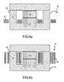
- FIGS. 6 a and 6 bare section views of a composite core from a conventional E-I structure showing the confinement of the magnetic flux within the core volume for both planar and vertical winding arrangements;
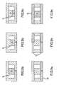
- FIGS. 7 a through 7 bare section views of a composite “EI” core for use in isolated and non-isolated power converters
- FIGS. 8 a through 8 care section views of alternate composite E-I cores for use in isolated or non-isolated power converter
- FIGS. 9 a through 9 care section views of additional composite E-I cores for use in non-isolated power converters.
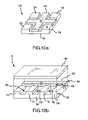
- FIGS. 10 a and 10 bare perspective views of “+” and “Extended-E” matrix integrated magnetics (MIM) cores.
- the present inventionprovides a magnetic core that reduces the fringing flux for both planar and vertical winding structures thereby lowering eddy current losses and loss of inductance.
- Airis an ideal gapping material from the perspective of preventing core saturation since it can support very high magnetic fields, it results in fringing flux due to its very low permeability compared to that of core materials.
- Airhas a relative permeability of one and does not saturate. In other words its saturation flux density is infinite. When the flux encounters an air gap in its magnetic path, a portion spills out of the air gap and impinges on the planar winding assembly inducing undesirable eddy currents. The fringing flux results in loss of inductance, which results in increased switching ripple leading to higher losses in the windings and semiconductor devices.
- the ideal materialwould have both an infinite saturation flux density to prevent core saturation and a high permeability to produce a desired inductance for a given number of windings thereby suppressing fringing flux. Unfortunately this ideal material does not exist.
- a composite core 50is formed of a high permeability material 52 and a low permeability, high saturation material 54 without an air gap.
- the high permeability section of the corehouses the windings where the magnetomotive force is generated and provides a path for the flux lines to close with minimal leakage.
- the composite coreis configured such that the low permeability material 54 is located where the flux accumulates from the high permeability sections of the core.
- the low permeability and high saturation flux density of the magnetic materialallows it to withstand high magnetic fields without saturation and provide localized energy storage similar to an air gap.
- magnetic material 54 with higher permeability than air in the space where the air gap would have existedkeeps the flux confined within the core thereby preventing fringing flux from spilling out into the winding arrangement.
- Introduction of the low permeability material 54 with a finite saturation flux density to replace the air gaprequires careful design of the complete core assembly to ensure that the flux density at each section of the core, in response to the applied magnetic field, does not exceed the saturation limit of the corresponding material used to synthesize that section of the core.
- high permeability materials 52include ferrites, laminated silicon steel and Metglas. Permeability of ferrites is in the 700–2000 range while that of silicon steel and Metglas laminations can be as high as 10,000.
- Examples of low permeability materials 54include powdered iron, magnetic nanocomposites and powdered permalloy.
- the saturation flux density of ferritesis in the 350–450 mT range, while that of laminated silicon steel and Metglas and low permeability materials such as powdered iron, magnetic nanocomposites and powdered permalloy is in the 1–2 T range.
- the permeabilities of the two materials that form the composite coreshould differ significantly to ensure that the energy is stored primarily in the low permeability section of the core.
- a typical permeability ratio between the two materialsis about 20:1 while a ratio is 10:1 is adequate to achieve satisfactory performance.
- a wide variation in permeabilityresults in the applied magnetomotive force to be almost entirely supported in the low permeability section of the composite core thereby allowing localized energy storage.
- the volume of low permeability material 54is necessarily greater than that of the air gap to compensate for its higher relative permeability and finite saturation flux density.
- this composite core configurationbalances the requirements of reducing fringing flux to lower eddy current losses and reduce loss of inductance while preventing core saturation without necessarily increasing either the height or width of the core or the number of winding turns.
- the composite core 50is configured such that the low permeability, high saturation material 54 is located where the flux accumulates from the high permeability sections 52 .
- the inductive components of the flux generated in the outer legs 68 and 70accumulate in the low permeability, high saturation center leg 72 .
- the transformer component of the fluxshould circulate in a high permeability path.
- a magnetic structure 60 for use in an isolated power converterincludes, for example, an E-I core 62 and a winding structure 64 .
- the coreincludes a base 66 , a pair of outer legs 68 and 70 , a center leg 72 and a plate 74 that rests on all three legs.
- the winding structureincludes windings 76 and 78 on the outer legs that form a split-primary windings, windings 80 and 82 on the outer legs that function both as secondary side and inductor windings, and a center leg winding 84 that forms an additional inductor winding.
- the flux 86includes the transformer component 88 that circulates in the outer legs 68 and 70 , the top plate 74 and the base 66 and inductive components 90 and 91 that flow through the outer legs 68 , 70 , center leg 72 , and complete through the top plate 74 and the base 66 .
- the center-leg winding 84is used to increase the effective filtering inductance and carries the full load current all the time.
- a portion 96 of the center leg 72is formed of the low permeability material 54 .
- the remainder of the coreis suitably formed from the high permeability material 52 . Alternate placements of the high saturation material portion 96 are illustrated in FIGS. 8 a – 8 c including the entire center leg, a middle portion of the leg or a lower portion of the leg.
- a magnetic structure 100 for use in a non-isolated power converter with integrated magneticsincludes, for example, an E-I core 102 and a winding structure 104 .
- the coreincludes a base 106 , a pair of outer legs 108 and 110 , a center leg 112 and a plate 114 that rests on all three legs.
- the winding structure 104includes three inductive windings 116 , 118 and 120 wound around the outer and center legs.
- the flux 122includes inductive components 124 and 126 that flow through the outer legs 108 , 110 , center leg 112 , and complete through the top plate 114 and the base 116 .
- the inductive components of the fluxaccumulate in the center leg, base and the top plate. Due to the absence of a transformer flux component for the non-isolated converter, there is no requirement to maintain a high permeability path.
- a portion 128 of the base, plate and/or the center legmay be formed from the high saturation material 54 .
- the remainder of the coreis suitably formed from the high permeability material 52 .
- Alternate placements of the low permeability material 128are illustrated in FIGS. 9 a – 9 c including the base, the base and plate, and the base, plate and center leg. The portion could be some or all of these components or combinations thereof.
- any of the configurations shown in FIGS. 7 a and 9 a – 9 care also suitable for a non-isolated power converter.
- Core structures shown in FIGS. 7 through 9are suitable for both planar and vertical winding structures.
- the low permeability material 54is used in the center leg of an E-core to replace the air gap therein, a first-order estimate of the height of the low permeability material, is determined by the height of the air gap it is replacing, the relative permeability of the material and cross sectional area of the center leg. Assuming constant cross section and constant number of windings, the estimate is the height of the air gap multiplied by the relative permeability of the material. Since the permeabilities are significantly different, the reluctance of the composite core is determined primarily by that of the low permeability section.
- the composite coremay be configured in any number of ways to implement a particular winding structure for both isolated and non-isolated power converters.
- the coremay be a conventional “E-I” as illustrated above or a conventional “E—E” structure.
- the coremay be formed as a coupled toroid or a matrix integrated magnetics (MIM) structure such as a “rectangular”, “radial” or “Extended-E”.
- MIMmatrix integrated magnetics
- the MIM core structuresare detailed in copending patent applications entitled ““Core Structure”, filed Apr. 18, 2002” and “Extended E Matrix Integrated Magnetics (MIM) Core” filed Aug. 19, 2004, which are incorporated by reference.
- the MIM coreprovides for ultra-low profile magnetics, resulting in better core utilization, larger inductance, improved efficiency and lower losses over conventional E-core designs.
- the MIM corecan also be configured in a cellular arrangement in a multi-phase configuration to effectively produce output voltages with reduced ripple or in multiple output converters.
- a rectangular MIM core structure 150provides four outer legs 152 , 154 , 156 and 158 at the corners of a base 160 .
- a shared center leg 162 in the shape of a cross or “+”is formed at the center of the base.
- a plate(not shown) rests on top of the four outer legs and shared center leg.
- the entire shared center leg 164is formed of a low permeability, high saturation material 54 and the remainder of the core is formed from a high permeability material 52 .
- Alternate embodiments consistent with those shown in FIGS. 7–9can be used in different power converters.
- an Extended-E core 170includes at least first, second and third outer legs 172 , 174 and 176 , respectively, disposed on the top region of a base 180 and separated along a first outer edge 182 to define first, second, . . . windows 184 , 186 , . . . therebetween.
- a fourth outer leg 188 and window 190are also included in this embodiment.
- a center leg 192formed from one or more pieces, is disposed on the top region 178 of the base 180 along a second outer edge 194 and separated from the first, second and third legs to define a center window 196 .
- the base 180 , outer legs 172 , 174 , 176 and 188 and the center leg 192may be produced as an integrated unit or produced separately and joined together.
- a plate 198is disposed on the outer and center legs opposite the base.
- the entire shared center leg 192is formed of a low permeability high saturation density material 54 and the remainder of the core is formed from a high permeability material 52 .
- Alternate embodiments consistent with those shown in FIGS. 7–9can be used in different power converters.
Landscapes
- Engineering & Computer Science (AREA)
- Power Engineering (AREA)
- Dc-Dc Converters (AREA)
Abstract
Description
Claims (21)
Priority Applications (1)
| Application Number | Priority Date | Filing Date | Title |
|---|---|---|---|
| US10/922,068US6980077B1 (en) | 2004-08-19 | 2004-08-19 | Composite magnetic core for switch-mode power converters |
Applications Claiming Priority (1)
| Application Number | Priority Date | Filing Date | Title |
|---|---|---|---|
| US10/922,068US6980077B1 (en) | 2004-08-19 | 2004-08-19 | Composite magnetic core for switch-mode power converters |
Publications (1)
| Publication Number | Publication Date |
|---|---|
| US6980077B1true US6980077B1 (en) | 2005-12-27 |
Family
ID=35482592
Family Applications (1)
| Application Number | Title | Priority Date | Filing Date |
|---|---|---|---|
| US10/922,068Expired - LifetimeUS6980077B1 (en) | 2004-08-19 | 2004-08-19 | Composite magnetic core for switch-mode power converters |
Country Status (1)
| Country | Link |
|---|---|
| US (1) | US6980077B1 (en) |
Cited By (159)
| Publication number | Priority date | Publication date | Assignee | Title |
|---|---|---|---|---|
| US20060018134A1 (en)* | 2003-08-11 | 2006-01-26 | Mamoru Tsuruya | Switching power supply device |
| US20060226477A1 (en)* | 2005-03-29 | 2006-10-12 | Brar Berinder P S | Substrate driven field-effect transistor |
| US20060226478A1 (en)* | 2005-03-29 | 2006-10-12 | Brar Berinder P S | Semiconductor device having a lateral channel and contacts on opposing surfaces thereof |
| US20060227482A1 (en)* | 2005-04-07 | 2006-10-12 | Shinji Ohta | Transformer and discharge lamp lighting device |
| US20060255360A1 (en)* | 2005-05-13 | 2006-11-16 | Brar Berinder P S | Semiconductor device having multiple lateral channels and method of forming the same |
| US20070045765A1 (en)* | 2005-08-25 | 2007-03-01 | Brar Berinder P | Semiconductor device having substrate-driven field-effect transistor and schottky diode and method of forming the same |
| US20070069286A1 (en)* | 2005-09-27 | 2007-03-29 | Brar Berinder P S | Semiconductor device having an interconnect with sloped walls and method of forming the same |
| US20070187717A1 (en)* | 2005-05-13 | 2007-08-16 | Coldwatt, Inc. | Semiconductor device having reduced on-resistance and method of forming the same |
| US7280026B2 (en) | 2002-04-18 | 2007-10-09 | Coldwatt, Inc. | Extended E matrix integrated magnetics (MIM) core |
| US7298118B2 (en) | 2005-02-23 | 2007-11-20 | Coldwatt, Inc. | Power converter employing a tapped inductor and integrated magnetics and method of operating the same |
| US20070296028A1 (en)* | 2006-06-21 | 2007-12-27 | Brar Berinder P S | Vertical Field-Effect Transistor and Method of Forming the Same |
| US20080012680A1 (en)* | 2006-07-13 | 2008-01-17 | Double Density Magnetics, Inc. | Devices and methods for redistributing magnetic flux density |
| US7321283B2 (en) | 2004-08-19 | 2008-01-22 | Coldwatt, Inc. | Vertical winding structures for planar magnetic switched-mode power converters |
| US20080048173A1 (en)* | 2005-08-25 | 2008-02-28 | Sadaka Mariam G | Semiconductor Device Including a Lateral Field-Effect Transistor and Schottky Diode |
| US20080067990A1 (en)* | 2006-09-19 | 2008-03-20 | Intersil Americas Inc. | Coupled-inductor assembly with partial winding |
| GB2442128A (en)* | 2006-09-21 | 2008-03-26 | Ford Global Tech Llc | Inductor core structures |
| US7385375B2 (en) | 2005-02-23 | 2008-06-10 | Coldwatt, Inc. | Control circuit for a depletion mode switch and method of operating the same |
| US7417875B2 (en)* | 2005-02-08 | 2008-08-26 | Coldwatt, Inc. | Power converter employing integrated magnetics with a current multiplier rectifier and method of operating the same |
| US20080224812A1 (en)* | 2007-03-14 | 2008-09-18 | Coldwatt, Inc. | Isolated power converter |
| US7427910B2 (en) | 2004-08-19 | 2008-09-23 | Coldwatt, Inc. | Winding structure for efficient switch-mode power converters |
| US20080303495A1 (en)* | 2007-06-08 | 2008-12-11 | Intersil Americas Inc. | Power supply with a magnetically uncoupled phase and an odd number of magnetically coupled phases, and control for a power supply with magnetically coupled and magnetically uncoupled phases |
| US20090045785A1 (en)* | 2007-08-14 | 2009-02-19 | Intersil Americas Inc. | Sensing a phase-path current in a multiphase power supply such as a coupled-inductor power supply |
| US20090059546A1 (en)* | 2007-08-31 | 2009-03-05 | Intersil Americas Inc. | Stackable electronic component |
| WO2009089507A1 (en)* | 2008-01-11 | 2009-07-16 | Mu-Gahat Holdings Inc. | Enhancing the efficiency of energy transfer to/from passive id circuits using ferrite cores |
| US20090231885A1 (en)* | 2008-03-17 | 2009-09-17 | Samsung Electro-Mechanics Co., Ltd. | Integrated transformer and power supply using the same |
| US20090230776A1 (en)* | 2008-03-17 | 2009-09-17 | Asic Advantage Inc. | Integrated multi-transformer |
| US20090237197A1 (en)* | 2008-03-14 | 2009-09-24 | Alexandr Ikriannikov | Method For Making Magnetic Components With M-Phase Coupling, And Related Inductor Structures |
| US20090256535A1 (en)* | 2008-04-10 | 2009-10-15 | Intersil Americas Inc. | Varying operation of a voltage regulator, and components thereof, based upon load conditions |
| US20090289773A1 (en)* | 2008-02-25 | 2009-11-26 | Mu-Gahat Holdings Inc. | Extending the read range of passive rfid tags |
| US20090295529A1 (en)* | 2008-05-28 | 2009-12-03 | Arturo Silva | Cross-core transformer |
| US20100013602A1 (en)* | 2008-04-21 | 2010-01-21 | Mu-Gahat Holdings Inc. | H-Field Shaping Using a Shorting Loop |
| US7663183B2 (en) | 2006-06-21 | 2010-02-16 | Flextronics International Usa, Inc. | Vertical field-effect transistor and method of forming the same |
| US7667986B2 (en) | 2006-12-01 | 2010-02-23 | Flextronics International Usa, Inc. | Power system with power converters having an adaptive controller |
| US7675759B2 (en) | 2006-12-01 | 2010-03-09 | Flextronics International Usa, Inc. | Power system with power converters having an adaptive controller |
| US7675758B2 (en) | 2006-12-01 | 2010-03-09 | Flextronics International Usa, Inc. | Power converter with an adaptive controller and method of operating the same |
| US20100176924A1 (en)* | 2009-01-09 | 2010-07-15 | Mu-Gahat Holdings Inc. | RFID System with Improved Tracking Position Accuracy |
| US20100245008A1 (en)* | 2009-03-30 | 2010-09-30 | Zhe Jiang University | Entirely integrated emi filter based on a flexible multi-layer strip material |
| US7876191B2 (en) | 2005-02-23 | 2011-01-25 | Flextronics International Usa, Inc. | Power converter employing a tapped inductor and integrated magnetics and method of operating the same |
| US20110035607A1 (en)* | 2009-08-10 | 2011-02-10 | Alexandr Ikriannikov | Coupled Inductor With Improved Leakage Inductance Control |
| US20110032068A1 (en)* | 2009-08-10 | 2011-02-10 | Alexandr Ikriannikov | Coupled Inductor With Improved Leakage Inductance Control |
| US7889517B2 (en) | 2006-12-01 | 2011-02-15 | Flextronics International Usa, Inc. | Power system with power converters having an adaptive controller |
| US20110043173A1 (en)* | 2007-09-13 | 2011-02-24 | Boris Blaumeiser | Multiphase dc to dc voltage converter |
| US7906941B2 (en) | 2007-06-19 | 2011-03-15 | Flextronics International Usa, Inc. | System and method for estimating input power for a power processing circuit |
| US20110063065A1 (en)* | 2009-09-17 | 2011-03-17 | Det International Holding Limited | Intergrated magnetic component |
| US20110074532A1 (en)* | 2009-09-30 | 2011-03-31 | Astec International Limited | Low Cost Charger Transformer |
| US20110080246A1 (en)* | 2006-09-21 | 2011-04-07 | Ford Global Technologies5 | Inductor topologies with substantial common-mode and differential-mode inductance |
| US20110148560A1 (en)* | 2009-12-21 | 2011-06-23 | Alexandr Ikriannikov | Two-Phase Coupled Inductors Which Promote Improved Printed Circuit Board Layout |
| US20110148559A1 (en)* | 2009-12-21 | 2011-06-23 | Alexandr Ikriannikov | multi-turn inductors |
| US20110169476A1 (en)* | 2010-01-14 | 2011-07-14 | Alexandr Ikriannikov | Asymmetrical Coupled Inductors And Associated Methods |
| CN102203885A (en)* | 2008-12-05 | 2011-09-28 | Abb研究有限公司 | A controllable reactor and fabrication method thereof |
| DE102010015410A1 (en)* | 2010-04-19 | 2011-10-20 | SUMIDA Components & Modules GmbH | Inductive component with variable core properties and method for their adjustment |
| CN102349120A (en)* | 2009-09-03 | 2012-02-08 | 松下电器产业株式会社 | Coil part and method for producing same |
| US8125205B2 (en) | 2006-08-31 | 2012-02-28 | Flextronics International Usa, Inc. | Power converter employing regulators with a coupled inductor |
| CN102446623A (en)* | 2010-10-13 | 2012-05-09 | 林志豪 | Asymmetric flat transformer |
| EP2453450A1 (en)* | 2010-11-12 | 2012-05-16 | Falco Electronics Ltd. | Hybrid core for power inductor |
| CN102576600A (en)* | 2009-10-29 | 2012-07-11 | 住友电气工业株式会社 | Reactor |
| US20120194313A1 (en)* | 2011-01-28 | 2012-08-02 | Uses, Inc. | Ac power conditioning circuit |
| US20120200382A1 (en)* | 2010-12-08 | 2012-08-09 | Epcos Ag | Inductive Device with Improved Core Properties |
| CN101552119B (en)* | 2007-12-11 | 2012-09-26 | 日立计算机机器株式会社 | Complex inductor and power supply unit |
| DE102010014281A9 (en)* | 2010-04-08 | 2012-11-29 | Exscitron Gmbh | Inductive electronic assembly and use of such |
| US20120313740A1 (en)* | 2010-02-25 | 2012-12-13 | Sumitomo Electric Industries, Ltd | Reactor and method for manufacturing reactor |
| US8350658B1 (en) | 2002-12-13 | 2013-01-08 | Volterra Semiconductor Corporation | Method for making magnetic components with N-phase coupling, and related inductor structures |
| CN102956344A (en)* | 2012-11-02 | 2013-03-06 | 华为技术有限公司 | Composite magnetic core structure and magnetic element |
| US8395470B2 (en)* | 2010-09-17 | 2013-03-12 | Chih-Hao Lin | Asymmetrical planar transformer having controllable leakage inductance |
| WO2011147451A3 (en)* | 2010-05-26 | 2013-03-28 | Abb Research Ltd | A wireless power receiving unit, a wireless power transferring unit, a wireless power transferring device and use of a wireless power transferring device |
| US8415737B2 (en) | 2006-06-21 | 2013-04-09 | Flextronics International Usa, Inc. | Semiconductor device with a pillar region and method of forming the same |
| US8416043B2 (en) | 2010-05-24 | 2013-04-09 | Volterra Semiconductor Corporation | Powder core material coupled inductors and associated methods |
| US20130093560A1 (en)* | 2011-10-18 | 2013-04-18 | Kabushiki Kaisha Toyota Jidoshokki | Magnetic core and induction device |
| EP2226819A4 (en)* | 2007-12-25 | 2013-05-29 | Panasonic Corp | PLANE COIL AND CONTACTLESS ENERGY TRANSMISSION DEVICE USING THE SAME |
| US20130201728A1 (en)* | 2012-02-02 | 2013-08-08 | Det International Holding Limited | Forward converter with magnetic component |
| US8514593B2 (en) | 2009-06-17 | 2013-08-20 | Power Systems Technologies, Ltd. | Power converter employing a variable switching frequency and a magnetic device with a non-uniform gap |
| CN103258624A (en)* | 2013-05-13 | 2013-08-21 | 田村(中国)企业管理有限公司 | Mixed magnetic circuit inductor |
| US8520414B2 (en) | 2009-01-19 | 2013-08-27 | Power Systems Technologies, Ltd. | Controller for a power converter |
| US8520420B2 (en) | 2009-12-18 | 2013-08-27 | Power Systems Technologies, Ltd. | Controller for modifying dead time between switches in a power converter |
| US20130241685A1 (en)* | 2008-10-31 | 2013-09-19 | Infineon Technologies Austria Ag | Method of Constructing Inductors and Transformers |
| DE102012106260A1 (en)* | 2012-07-12 | 2014-01-16 | Hella Kgaa Hueck & Co. | Multiphase stray field transformer for storage and filtering |
| US8638578B2 (en) | 2009-08-14 | 2014-01-28 | Power System Technologies, Ltd. | Power converter including a charge pump employable in a power adapter |
| US8643222B2 (en) | 2009-06-17 | 2014-02-04 | Power Systems Technologies Ltd | Power adapter employing a power reducer |
| US8674802B2 (en) | 2009-12-21 | 2014-03-18 | Volterra Semiconductor Corporation | Multi-turn inductors |
| US8767418B2 (en) | 2010-03-17 | 2014-07-01 | Power Systems Technologies Ltd. | Control system for a power converter and method of operating the same |
| US8787043B2 (en) | 2010-01-22 | 2014-07-22 | Power Systems Technologies, Ltd. | Controller for a power converter and method of operating the same |
| US8792257B2 (en) | 2011-03-25 | 2014-07-29 | Power Systems Technologies, Ltd. | Power converter with reduced power dissipation |
| US8792256B2 (en) | 2012-01-27 | 2014-07-29 | Power Systems Technologies Ltd. | Controller for a switch and method of operating the same |
| US20140266535A1 (en)* | 2013-03-14 | 2014-09-18 | Hiq Solar, Inc. | Low loss inductor with offset gap and windings |
| US8866575B2 (en)* | 2011-01-28 | 2014-10-21 | Uses, Inc. | AC power conditioning circuit |
| EP2797087A1 (en)* | 2013-04-25 | 2014-10-29 | Delta Electronics, Inc. | Magnetic core and magnetic component using the same |
| US8896403B2 (en) | 2009-10-19 | 2014-11-25 | Exscitron Gmbh | Inductive electronic module and use thereof |
| US8902032B2 (en) | 2011-10-18 | 2014-12-02 | Kabushiki Kaisha Toyota Jidoshokki | Induction device |
| US8907759B2 (en) | 2011-10-18 | 2014-12-09 | Kabushiki Kaisha Toyota Jidoshokki | Magnetic core and induction device |
| US8952776B2 (en) | 2002-12-13 | 2015-02-10 | Volterra Semiconductor Corporation | Powder core material coupled inductors and associated methods |
| US8963521B2 (en) | 2007-06-08 | 2015-02-24 | Intersil Americas LLC | Power supply with a magnetically uncoupled phase and an odd number of magnetically coupled phases, and control for a power supply with magnetically coupled and magnetically uncoupled phases |
| US8975995B1 (en) | 2012-08-29 | 2015-03-10 | Volterra Semiconductor Corporation | Coupled inductors with leakage plates, and associated systems and methods |
| US8976549B2 (en) | 2009-12-03 | 2015-03-10 | Power Systems Technologies, Ltd. | Startup circuit including first and second Schmitt triggers and power converter employing the same |
| US9013259B2 (en) | 2010-05-24 | 2015-04-21 | Volterra Semiconductor Corporation | Powder core material coupled inductors and associated methods |
| US9019061B2 (en) | 2009-03-31 | 2015-04-28 | Power Systems Technologies, Ltd. | Magnetic device formed with U-shaped core pieces and power converter employing the same |
| US9019063B2 (en) | 2009-08-10 | 2015-04-28 | Volterra Semiconductor Corporation | Coupled inductor with improved leakage inductance control |
| CN104715899A (en)* | 2013-12-12 | 2015-06-17 | 台达电子企业管理(上海)有限公司 | Three-phase electric reactor |
| US9077248B2 (en) | 2009-06-17 | 2015-07-07 | Power Systems Technologies Ltd | Start-up circuit for a power adapter |
| US9088216B2 (en) | 2009-01-19 | 2015-07-21 | Power Systems Technologies, Ltd. | Controller for a synchronous rectifier switch |
| US9099232B2 (en) | 2012-07-16 | 2015-08-04 | Power Systems Technologies Ltd. | Magnetic device and power converter employing the same |
| US9106130B2 (en) | 2012-07-16 | 2015-08-11 | Power Systems Technologies, Inc. | Magnetic device and power converter employing the same |
| US20150235754A1 (en)* | 2014-02-17 | 2015-08-20 | Volterra Semiconductor Corporation | Ferrite inductors for low-height and associated methods |
| US20150235749A1 (en)* | 2014-02-14 | 2015-08-20 | Delta Electronics (Shanghai) Co., Ltd. | Magnetic core |
| CN104969309A (en)* | 2012-12-21 | 2015-10-07 | 法雷奥电机控制系统公司 | Magnetic circuit for carrying at least one coil |
| US20150287512A1 (en)* | 2014-04-03 | 2015-10-08 | SUMIDA Components & Modules GmbH | Choke and choke core |
| US9190898B2 (en) | 2012-07-06 | 2015-11-17 | Power Systems Technologies, Ltd | Controller for a power converter and method of operating the same |
| US9197132B2 (en) | 2006-12-01 | 2015-11-24 | Flextronics International Usa, Inc. | Power converter with an adaptive controller and method of operating the same |
| US9214264B2 (en) | 2012-07-16 | 2015-12-15 | Power Systems Technologies, Ltd. | Magnetic device and power converter employing the same |
| US9240712B2 (en) | 2012-12-13 | 2016-01-19 | Power Systems Technologies Ltd. | Controller including a common current-sense device for power switches of a power converter |
| US9246391B2 (en) | 2010-01-22 | 2016-01-26 | Power Systems Technologies Ltd. | Controller for providing a corrected signal to a sensed peak current through a circuit element of a power converter |
| CN105374530A (en)* | 2014-08-21 | 2016-03-02 | 群光电能科技股份有限公司 | Power factor corrector and inductor thereof |
| US9287038B2 (en) | 2013-03-13 | 2016-03-15 | Volterra Semiconductor LLC | Coupled inductors with non-uniform winding terminal distributions |
| US9300206B2 (en) | 2013-11-15 | 2016-03-29 | Power Systems Technologies Ltd. | Method for estimating power of a power converter |
| US9318253B2 (en)* | 2014-05-02 | 2016-04-19 | Hamilton Sundstrand Corporation | Hybrid planar common-mode choke |
| US20160126829A1 (en)* | 2014-11-05 | 2016-05-05 | Chicony Power Technology Co., Ltd. | Inductor and power factor corrector using the same |
| US9336941B1 (en) | 2013-10-30 | 2016-05-10 | Volterra Semiconductor LLC | Multi-row coupled inductors and associated systems and methods |
| EP3032549A1 (en)* | 2014-12-11 | 2016-06-15 | LG Innotek Co., Ltd. | Inductor |
| US9373438B1 (en) | 2011-11-22 | 2016-06-21 | Volterra Semiconductor LLC | Coupled inductor arrays and associated methods |
| US9379629B2 (en) | 2012-07-16 | 2016-06-28 | Power Systems Technologies, Ltd. | Magnetic device and power converter employing the same |
| US20160189847A1 (en)* | 2014-09-24 | 2016-06-30 | Hiq Solar, Inc. | Novel construction of double gap inductor |
| US20170040097A1 (en)* | 2014-05-28 | 2017-02-09 | Abb Ag | Switching converter circuit with an integrated transformer |
| EP3136404A4 (en)* | 2014-05-27 | 2017-05-17 | Huawei Technologies Co. Ltd. | Coupling inductor and power converter |
| US9691538B1 (en) | 2012-08-30 | 2017-06-27 | Volterra Semiconductor LLC | Magnetic devices for power converters with light load enhancers |
| US9767947B1 (en) | 2011-03-02 | 2017-09-19 | Volterra Semiconductor LLC | Coupled inductors enabling increased switching stage pitch |
| CN107302298A (en)* | 2016-03-31 | 2017-10-27 | 台达电子企业管理(上海)有限公司 | Power module with two-way or multiple-channel output voltage |
| US9837194B1 (en)* | 2015-10-07 | 2017-12-05 | Universal Lighting Technologies, Inc. | Output transformer and resonant inductor in a combined magnetic structure |
| US20180053596A1 (en)* | 2016-08-19 | 2018-02-22 | Maxim Integrated Products, Inc. | Coupled inductors for low electromagnetic interference |
| EP3349224A1 (en) | 2017-01-12 | 2018-07-18 | DET International Holding Limited | Integrated magnetic component and switched mode power converter |
| US20180218828A1 (en)* | 2017-01-27 | 2018-08-02 | Toyota Motor Engineering & Manufacturing North America, Inc. | Inductor with variable permeability core |
| US20180254137A1 (en)* | 2012-08-21 | 2018-09-06 | Cyntec Co., Ltd. | Variable Coupled Inductor |
| US10083790B1 (en) | 2017-02-06 | 2018-09-25 | Universal Lighting Technologies | Method and apparatus for attaching magnetic components to printed circuit boards |
| US20180308615A1 (en)* | 2017-04-25 | 2018-10-25 | Delta Electronics, Inc. | Magnetic assembly, inductor and transformer |
| US10128035B2 (en) | 2011-11-22 | 2018-11-13 | Volterra Semiconductor LLC | Coupled inductor arrays and associated methods |
| US10163561B1 (en) | 2015-12-11 | 2018-12-25 | Bel Power Solutions Inc. | Distributed planar inductor with multi-2D geometry for energy storage |
| DE102017114900A1 (en)* | 2017-07-04 | 2019-01-10 | Bayerische Motoren Werke Aktiengesellschaft | Power inductor |
| DE102018203054A1 (en)* | 2018-03-01 | 2019-09-05 | Bayerische Motoren Werke Aktiengesellschaft | Voltage transformer with coupled PFC choke |
| US10546682B2 (en)* | 2018-01-17 | 2020-01-28 | Tokin Corporation | Reactor and step-up circuit |
| US10553339B1 (en) | 2018-03-30 | 2020-02-04 | Universal Lighting Technologies, Inc. | Common-mode choke with integrated RF inductor winding |
| JP2021507534A (en)* | 2017-12-20 | 2021-02-22 | ロベルト・ボッシュ・ゲゼルシャフト・ミト・ベシュレンクテル・ハフツングRobert Bosch Gmbh | Transformer core and transformer |
| US10945320B1 (en) | 2019-10-07 | 2021-03-09 | Universal Lighting Technologies, Inc. | Output voltage control method to avoid LED turn-on flash |
| CN112652465A (en)* | 2019-10-09 | 2021-04-13 | 电力集成公司 | Magnet with multiple discs |
| US11189415B2 (en)* | 2017-07-13 | 2021-11-30 | Delta Electronics (Shanghai) Co., Ltd | Magnetic element and switching power supply using the same |
| US20210407727A1 (en)* | 2020-06-24 | 2021-12-30 | Murata Manufacturing Co., Ltd. | Integrated embedded transformer module |
| US11250984B2 (en)* | 2019-05-31 | 2022-02-15 | Power Integrations, Inc. | Methods and apparatus for biasing a magnetic circuit to reduce audible noise from a switching power supply |
| US11309109B2 (en)* | 2015-12-17 | 2022-04-19 | Commissariat A L'energie Atomique Et Aux Energies Alternatives | Inductive core exhibiting low magnetic losses |
| FR3116372A1 (en)* | 2020-11-18 | 2022-05-20 | Valeo Siemens Eautomotive France Sas | ELECTRICAL DEVICE WITH TWO GROUPS OF COUPLED COILS CARRIED BY A PRINTED CIRCUIT BOARD, VOLTAGE CONVERTER COMPRISING SUCH ELECTRICAL DEVICE AND METHOD FOR MANUFACTURING SUCH ELECTRICAL DEVICE |
| US11342114B2 (en)* | 2016-07-13 | 2022-05-24 | Mitsubishi Electric Corporation | Leakage transformer |
| WO2022104897A1 (en)* | 2020-11-18 | 2022-05-27 | 深圳顺络汽车电子有限公司 | Novel low-loss transformer |
| US11404203B2 (en) | 2018-06-13 | 2022-08-02 | General Electric Company | Magnetic unit and an associated method thereof |
| US20220336138A1 (en)* | 2021-04-20 | 2022-10-20 | Delta Electronics, Inc. | Magnetic device and power conversion module |
| US11482369B2 (en)* | 2016-12-20 | 2022-10-25 | Lg Innotek Co., Ltd. | Magnetic core, coil component, and electronic component including same |
| CN115583832A (en)* | 2022-09-09 | 2023-01-10 | 华为数字能源技术有限公司 | Magnetic core and preparation method thereof, common-mode inductor and electronic device |
| US20230025521A1 (en)* | 2021-07-16 | 2023-01-26 | Navitas Semiconductor Limited | Planar transformers with multiple magnetic materials |
| CN116076011A (en)* | 2022-10-12 | 2023-05-05 | 英诺赛科(深圳)半导体有限公司 | GaN-based switch mode power supply with planar transformer |
| WO2023224818A1 (en)* | 2022-05-16 | 2023-11-23 | Apple Inc. | Quasi-planar transformer construction |
| US20240013964A1 (en)* | 2019-06-21 | 2024-01-11 | Panasonic Intellectual Property Management Co., Ltd. | Core |
| WO2024216904A1 (en)* | 2023-04-18 | 2024-10-24 | 北京国家新能源汽车技术创新中心有限公司 | Inductor magnetic core, inductor, and electromagnetic interference filter |
| EP4435806A3 (en)* | 2023-03-24 | 2024-12-18 | Cyntec Co., Ltd. | Magnetic component |
| US12431281B2 (en) | 2022-05-16 | 2025-09-30 | Apple Inc. | Quasi-planar transformer construction |
Citations (11)
| Publication number | Priority date | Publication date | Assignee | Title |
|---|---|---|---|---|
| US3433998A (en)* | 1965-04-24 | 1969-03-18 | Philips Corp | Circuit arrangement for frame correction |
| US3622868A (en)* | 1970-02-06 | 1971-11-23 | Joachim H Todt | Regulating power transformer with magnetic shunt |
| JPH03215911A (en) | 1990-01-19 | 1991-09-20 | Matsushita Electric Ind Co Ltd | Variable inductor |
| US5126714A (en) | 1990-12-20 | 1992-06-30 | The United States Of America As Represented By The Secretary Of The Navy | Integrated circuit transformer |
| US5134771A (en)* | 1991-07-05 | 1992-08-04 | General Electric Company | Method for manufacturing and amorphous metal core for a transformer that includes steps for reducing core loss |
| US5335163A (en)* | 1990-11-14 | 1994-08-02 | Scanpower | Power supply circuit with integrated magnetic components |
| US5784266A (en) | 1996-06-14 | 1998-07-21 | Virginia Power Technologies, Inc | Single magnetic low loss high frequency converter |
| US6348848B1 (en) | 2000-05-04 | 2002-02-19 | Edward Herbert | Transformer having fractional turn windings |
| US6362986B1 (en) | 2001-03-22 | 2002-03-26 | Volterra, Inc. | Voltage converter with coupled inductive windings, and associated methods |
| US20020114172A1 (en) | 2001-02-19 | 2002-08-22 | Rockwell Scientific Company, Llc | Converter circuit and method with auxiliary supply voltage |
| US6549436B1 (en) | 2002-02-21 | 2003-04-15 | Innovative Technology Licensing Llc | Integrated magnetic converter circuit and method with improved filtering |
- 2004
- 2004-08-19USUS10/922,068patent/US6980077B1/ennot_activeExpired - Lifetime
Patent Citations (11)
| Publication number | Priority date | Publication date | Assignee | Title |
|---|---|---|---|---|
| US3433998A (en)* | 1965-04-24 | 1969-03-18 | Philips Corp | Circuit arrangement for frame correction |
| US3622868A (en)* | 1970-02-06 | 1971-11-23 | Joachim H Todt | Regulating power transformer with magnetic shunt |
| JPH03215911A (en) | 1990-01-19 | 1991-09-20 | Matsushita Electric Ind Co Ltd | Variable inductor |
| US5335163A (en)* | 1990-11-14 | 1994-08-02 | Scanpower | Power supply circuit with integrated magnetic components |
| US5126714A (en) | 1990-12-20 | 1992-06-30 | The United States Of America As Represented By The Secretary Of The Navy | Integrated circuit transformer |
| US5134771A (en)* | 1991-07-05 | 1992-08-04 | General Electric Company | Method for manufacturing and amorphous metal core for a transformer that includes steps for reducing core loss |
| US5784266A (en) | 1996-06-14 | 1998-07-21 | Virginia Power Technologies, Inc | Single magnetic low loss high frequency converter |
| US6348848B1 (en) | 2000-05-04 | 2002-02-19 | Edward Herbert | Transformer having fractional turn windings |
| US20020114172A1 (en) | 2001-02-19 | 2002-08-22 | Rockwell Scientific Company, Llc | Converter circuit and method with auxiliary supply voltage |
| US6362986B1 (en) | 2001-03-22 | 2002-03-26 | Volterra, Inc. | Voltage converter with coupled inductive windings, and associated methods |
| US6549436B1 (en) | 2002-02-21 | 2003-04-15 | Innovative Technology Licensing Llc | Integrated magnetic converter circuit and method with improved filtering |
Non-Patent Citations (1)
| Title |
|---|
| Xu, et al., Design of 48V Voltage Regulator Modules with a Novel Integrated Magnetics, IEEE Transactions on Power Electronics, vol. 17, No. 6 (Nov. 2002), pp. 990-998. |
Cited By (275)
| Publication number | Priority date | Publication date | Assignee | Title |
|---|---|---|---|---|
| US7633369B2 (en) | 2002-04-18 | 2009-12-15 | Flextronics International Usa, Inc. | Extended E matrix integrated magnetics (MIM) core |
| US8134443B2 (en) | 2002-04-18 | 2012-03-13 | Flextronics International Usa, Inc. | Extended E matrix integrated magnetics (MIM) core |
| US7280026B2 (en) | 2002-04-18 | 2007-10-09 | Coldwatt, Inc. | Extended E matrix integrated magnetics (MIM) core |
| US8847722B2 (en) | 2002-12-13 | 2014-09-30 | Volterra Semiconductor Corporation | Method for making magnetic components with N-phase coupling, and related inductor structures |
| US8350658B1 (en) | 2002-12-13 | 2013-01-08 | Volterra Semiconductor Corporation | Method for making magnetic components with N-phase coupling, and related inductor structures |
| US8952776B2 (en) | 2002-12-13 | 2015-02-10 | Volterra Semiconductor Corporation | Powder core material coupled inductors and associated methods |
| US7405951B2 (en)* | 2003-08-11 | 2008-07-29 | Sanken Electric Co., Ltd. | Switching power supply device |
| US20060018134A1 (en)* | 2003-08-11 | 2006-01-26 | Mamoru Tsuruya | Switching power supply device |
| US7321283B2 (en) | 2004-08-19 | 2008-01-22 | Coldwatt, Inc. | Vertical winding structures for planar magnetic switched-mode power converters |
| US7427910B2 (en) | 2004-08-19 | 2008-09-23 | Coldwatt, Inc. | Winding structure for efficient switch-mode power converters |
| US7554430B2 (en) | 2004-08-19 | 2009-06-30 | Flextronics International Usa, Inc. | Vertical winding structures for planar magnetic switched-mode power converters |
| US7675764B2 (en) | 2005-02-08 | 2010-03-09 | Flextronics International Usa, Inc. | Power converter employing integrated magnetics with a current multiplier rectifier and method of operating the same |
| US7417875B2 (en)* | 2005-02-08 | 2008-08-26 | Coldwatt, Inc. | Power converter employing integrated magnetics with a current multiplier rectifier and method of operating the same |
| US7385375B2 (en) | 2005-02-23 | 2008-06-10 | Coldwatt, Inc. | Control circuit for a depletion mode switch and method of operating the same |
| US7298118B2 (en) | 2005-02-23 | 2007-11-20 | Coldwatt, Inc. | Power converter employing a tapped inductor and integrated magnetics and method of operating the same |
| US7876191B2 (en) | 2005-02-23 | 2011-01-25 | Flextronics International Usa, Inc. | Power converter employing a tapped inductor and integrated magnetics and method of operating the same |
| US7439557B2 (en) | 2005-03-29 | 2008-10-21 | Coldwatt, Inc. | Semiconductor device having a lateral channel and contacts on opposing surfaces thereof |
| US20070145417A1 (en)* | 2005-03-29 | 2007-06-28 | Brar Berinder P S | High voltage semiconductor device having a lateral channel and enhanced gate-to-drain separation |
| US7439556B2 (en) | 2005-03-29 | 2008-10-21 | Coldwatt, Inc. | Substrate driven field-effect transistor |
| US20060226478A1 (en)* | 2005-03-29 | 2006-10-12 | Brar Berinder P S | Semiconductor device having a lateral channel and contacts on opposing surfaces thereof |
| US20060226477A1 (en)* | 2005-03-29 | 2006-10-12 | Brar Berinder P S | Substrate driven field-effect transistor |
| US7176775B2 (en)* | 2005-04-07 | 2007-02-13 | Koito Manufacturing Co., Ltd. | Transformer and discharge lamp lighting device |
| US20060227482A1 (en)* | 2005-04-07 | 2006-10-12 | Shinji Ohta | Transformer and discharge lamp lighting device |
| US20070187717A1 (en)* | 2005-05-13 | 2007-08-16 | Coldwatt, Inc. | Semiconductor device having reduced on-resistance and method of forming the same |
| US7838905B2 (en) | 2005-05-13 | 2010-11-23 | Flextronics International Usa, Inc. | Semiconductor device having multiple lateral channels and method of forming the same |
| US20060255360A1 (en)* | 2005-05-13 | 2006-11-16 | Brar Berinder P S | Semiconductor device having multiple lateral channels and method of forming the same |
| US7339208B2 (en) | 2005-05-13 | 2008-03-04 | Coldwatt, Inc. | Semiconductor device having multiple lateral channels and method of forming the same |
| US7675090B2 (en) | 2005-05-13 | 2010-03-09 | Flextronics International Usa, Inc. | Semiconductor device having a contact on a buffer layer thereof and method of forming the same |
| US7564074B2 (en) | 2005-08-25 | 2009-07-21 | Flextronics International Usa, Inc. | Semiconductor device including a lateral field-effect transistor and Schottky diode |
| US7655963B2 (en) | 2005-08-25 | 2010-02-02 | Flextronics International Usa, Inc. | Semiconductor device including a lateral field-effect transistor and Schottky diode |
| US7642568B2 (en) | 2005-08-25 | 2010-01-05 | Flextronics International Usa, Inc. | Semiconductor device having substrate-driven field-effect transistor and Schottky diode and method of forming the same |
| US20080048173A1 (en)* | 2005-08-25 | 2008-02-28 | Sadaka Mariam G | Semiconductor Device Including a Lateral Field-Effect Transistor and Schottky Diode |
| US20080048219A1 (en)* | 2005-08-25 | 2008-02-28 | Brar Berinder P S | Semiconductor Device Having Substrate-Driven Field-Effect Transistor and Schottky Diode and Method of Forming the Same |
| US7285807B2 (en) | 2005-08-25 | 2007-10-23 | Coldwatt, Inc. | Semiconductor device having substrate-driven field-effect transistor and Schottky diode and method of forming the same |
| US20070045765A1 (en)* | 2005-08-25 | 2007-03-01 | Brar Berinder P | Semiconductor device having substrate-driven field-effect transistor and schottky diode and method of forming the same |
| US20080054304A1 (en)* | 2005-08-25 | 2008-03-06 | Sadaka Mariam G | Semiconductor Device Including a Lateral Field-Effect Transistor and Schottky Diode |
| US7504673B2 (en) | 2005-08-25 | 2009-03-17 | Flextronics International Usa, Inc. | Semiconductor device including a lateral field-effect transistor and Schottky diode |
| US7462891B2 (en) | 2005-09-27 | 2008-12-09 | Coldwatt, Inc. | Semiconductor device having an interconnect with sloped walls and method of forming the same |
| US20070069286A1 (en)* | 2005-09-27 | 2007-03-29 | Brar Berinder P S | Semiconductor device having an interconnect with sloped walls and method of forming the same |
| US8415737B2 (en) | 2006-06-21 | 2013-04-09 | Flextronics International Usa, Inc. | Semiconductor device with a pillar region and method of forming the same |
| US7541640B2 (en) | 2006-06-21 | 2009-06-02 | Flextronics International Usa, Inc. | Vertical field-effect transistor and method of forming the same |
| US20070296028A1 (en)* | 2006-06-21 | 2007-12-27 | Brar Berinder P S | Vertical Field-Effect Transistor and Method of Forming the Same |
| US7663183B2 (en) | 2006-06-21 | 2010-02-16 | Flextronics International Usa, Inc. | Vertical field-effect transistor and method of forming the same |
| US20080012680A1 (en)* | 2006-07-13 | 2008-01-17 | Double Density Magnetics, Inc. | Devices and methods for redistributing magnetic flux density |
| WO2008008382A3 (en)* | 2006-07-13 | 2008-10-30 | Double Density Magnetics Inc | Devices and methods for redistributing magnetic flux density |
| US7864013B2 (en)* | 2006-07-13 | 2011-01-04 | Double Density Magnetics Inc. | Devices and methods for redistributing magnetic flux density |
| US8125205B2 (en) | 2006-08-31 | 2012-02-28 | Flextronics International Usa, Inc. | Power converter employing regulators with a coupled inductor |
| US20080067990A1 (en)* | 2006-09-19 | 2008-03-20 | Intersil Americas Inc. | Coupled-inductor assembly with partial winding |
| US20110080246A1 (en)* | 2006-09-21 | 2011-04-07 | Ford Global Technologies5 | Inductor topologies with substantial common-mode and differential-mode inductance |
| US20080074230A1 (en)* | 2006-09-21 | 2008-03-27 | Ford Motor Company | Variable permeability inductor cre structures |
| GB2442128A (en)* | 2006-09-21 | 2008-03-26 | Ford Global Tech Llc | Inductor core structures |
| US7889517B2 (en) | 2006-12-01 | 2011-02-15 | Flextronics International Usa, Inc. | Power system with power converters having an adaptive controller |
| US9197132B2 (en) | 2006-12-01 | 2015-11-24 | Flextronics International Usa, Inc. | Power converter with an adaptive controller and method of operating the same |
| US7667986B2 (en) | 2006-12-01 | 2010-02-23 | Flextronics International Usa, Inc. | Power system with power converters having an adaptive controller |
| US8477514B2 (en) | 2006-12-01 | 2013-07-02 | Flextronics International Usa, Inc. | Power system with power converters having an adaptive controller |
| US7675759B2 (en) | 2006-12-01 | 2010-03-09 | Flextronics International Usa, Inc. | Power system with power converters having an adaptive controller |
| US7675758B2 (en) | 2006-12-01 | 2010-03-09 | Flextronics International Usa, Inc. | Power converter with an adaptive controller and method of operating the same |
| US20080224812A1 (en)* | 2007-03-14 | 2008-09-18 | Coldwatt, Inc. | Isolated power converter |
| US8502520B2 (en) | 2007-03-14 | 2013-08-06 | Flextronics International Usa, Inc | Isolated power converter |
| US7468649B2 (en) | 2007-03-14 | 2008-12-23 | Flextronics International Usa, Inc. | Isolated power converter |
| US20080303495A1 (en)* | 2007-06-08 | 2008-12-11 | Intersil Americas Inc. | Power supply with a magnetically uncoupled phase and an odd number of magnetically coupled phases, and control for a power supply with magnetically coupled and magnetically uncoupled phases |
| US8179116B2 (en) | 2007-06-08 | 2012-05-15 | Intersil Americas LLC | Inductor assembly having a core with magnetically isolated forms |
| US8570009B2 (en) | 2007-06-08 | 2013-10-29 | Intersil Americas Inc. | Power supply with a magnetically uncoupled phase and an odd number of magnetically coupled phases, and control for a power supply with magnetically coupled and magnetically uncoupled phases |
| US20080309299A1 (en)* | 2007-06-08 | 2008-12-18 | Intersil Americas Inc. | Inductor assembly having a core with magnetically isolated forms |
| US8963521B2 (en) | 2007-06-08 | 2015-02-24 | Intersil Americas LLC | Power supply with a magnetically uncoupled phase and an odd number of magnetically coupled phases, and control for a power supply with magnetically coupled and magnetically uncoupled phases |
| US20080315982A1 (en)* | 2007-06-08 | 2008-12-25 | Intersil Americas Inc. | Coupled-inductor core for unbalanced phase currents |
| US7906941B2 (en) | 2007-06-19 | 2011-03-15 | Flextronics International Usa, Inc. | System and method for estimating input power for a power processing circuit |
| US9602005B2 (en) | 2007-08-14 | 2017-03-21 | Intersil Americas LLC | Sensing a phase-path current in a coupled-inductor power supply |
| US20090045785A1 (en)* | 2007-08-14 | 2009-02-19 | Intersil Americas Inc. | Sensing a phase-path current in a multiphase power supply such as a coupled-inductor power supply |
| US8704500B2 (en) | 2007-08-14 | 2014-04-22 | Intersil Americas LLC | Sensing a phase-path current in a multiphase power supply such as a coupled-inductor power supply |
| US20090059546A1 (en)* | 2007-08-31 | 2009-03-05 | Intersil Americas Inc. | Stackable electronic component |
| US8320136B2 (en) | 2007-08-31 | 2012-11-27 | Intersil Americas Inc. | Stackable electronic component |
| US8570022B2 (en)* | 2007-09-13 | 2013-10-29 | Robert Bosch Gmbh | Multiphase DC to DC voltage converter |
| US20110043173A1 (en)* | 2007-09-13 | 2011-02-24 | Boris Blaumeiser | Multiphase dc to dc voltage converter |
| CN101552119B (en)* | 2007-12-11 | 2012-09-26 | 日立计算机机器株式会社 | Complex inductor and power supply unit |
| EP2226819A4 (en)* | 2007-12-25 | 2013-05-29 | Panasonic Corp | PLANE COIL AND CONTACTLESS ENERGY TRANSMISSION DEVICE USING THE SAME |
| US8432283B2 (en) | 2008-01-11 | 2013-04-30 | Magnet Consulting, Inc. | Enhancing the efficiency of energy transfer to/from passive ID circuits using ferrite cores |
| US20090179741A1 (en)* | 2008-01-11 | 2009-07-16 | Mu-Gahat Holdings Inc. | Enhancing the efficiency of energy transfer to/from passive id circuits using ferrite cores |
| WO2009089507A1 (en)* | 2008-01-11 | 2009-07-16 | Mu-Gahat Holdings Inc. | Enhancing the efficiency of energy transfer to/from passive id circuits using ferrite cores |
| US8988224B2 (en) | 2008-01-11 | 2015-03-24 | Magnet Consulting, Inc. | Enhancing the efficiency of energy transfer to/from passive ID circuits using ferrite cores |
| US20090289773A1 (en)* | 2008-02-25 | 2009-11-26 | Mu-Gahat Holdings Inc. | Extending the read range of passive rfid tags |
| US8395525B2 (en) | 2008-02-25 | 2013-03-12 | Magnet Consulting, Inc. | Extending the read range of passive RFID tags |
| US8294544B2 (en) | 2008-03-14 | 2012-10-23 | Volterra Semiconductor Corporation | Method for making magnetic components with M-phase coupling, and related inductor structures |
| US9627125B2 (en) | 2008-03-14 | 2017-04-18 | Volterra Semiconductor LLC | Voltage converter inductor having a nonlinear inductance value |
| US20090237197A1 (en)* | 2008-03-14 | 2009-09-24 | Alexandr Ikriannikov | Method For Making Magnetic Components With M-Phase Coupling, And Related Inductor Structures |
| US8836463B2 (en) | 2008-03-14 | 2014-09-16 | Volterra Semiconductor Corporation | Voltage converter inductor having a nonlinear inductance value |
| US8223509B2 (en) | 2008-03-17 | 2012-07-17 | Samsung Electro-Mechanics Co., Ltd. | Integrated transformer and power supply using the same |
| US20090230776A1 (en)* | 2008-03-17 | 2009-09-17 | Asic Advantage Inc. | Integrated multi-transformer |
| US20090231885A1 (en)* | 2008-03-17 | 2009-09-17 | Samsung Electro-Mechanics Co., Ltd. | Integrated transformer and power supply using the same |
| US7956491B2 (en)* | 2008-03-17 | 2011-06-07 | Asic Advantage Inc. | Integrated multi-transformer |
| US8125207B2 (en) | 2008-04-10 | 2012-02-28 | Intersil Americas Inc. | Varying operation of a voltage regulator, and components thereof, based upon load conditions |
| USRE45773E1 (en) | 2008-04-10 | 2015-10-20 | Intersil Americas Inc. | Varying operation of a voltage regulator, and components thereof, based upon load conditions |
| US7898236B2 (en) | 2008-04-10 | 2011-03-01 | Intersil Americas Inc. | Varying operation of a voltage regulator, and components thereof, based upon load conditions |
| US20090256535A1 (en)* | 2008-04-10 | 2009-10-15 | Intersil Americas Inc. | Varying operation of a voltage regulator, and components thereof, based upon load conditions |
| US20110062930A1 (en)* | 2008-04-10 | 2011-03-17 | Intersil Americas Inc. | Varying operation of a voltage regulator, and components thereof, based upon load conditions |
| US8395507B2 (en) | 2008-04-21 | 2013-03-12 | Magnet Consulting, Inc. | H-field shaping using a shorting loop |
| US8981940B2 (en) | 2008-04-21 | 2015-03-17 | Magnet Consulting, Inc. | H-field shaping using a shorting loop |
| US20100013602A1 (en)* | 2008-04-21 | 2010-01-21 | Mu-Gahat Holdings Inc. | H-Field Shaping Using a Shorting Loop |
| US7948348B2 (en)* | 2008-05-28 | 2011-05-24 | Flextronics Ap, Llc | Cross-core transformer |
| US20090295529A1 (en)* | 2008-05-28 | 2009-12-03 | Arturo Silva | Cross-core transformer |
| US20130241685A1 (en)* | 2008-10-31 | 2013-09-19 | Infineon Technologies Austria Ag | Method of Constructing Inductors and Transformers |
| CN102203885A (en)* | 2008-12-05 | 2011-09-28 | Abb研究有限公司 | A controllable reactor and fabrication method thereof |
| US20100176924A1 (en)* | 2009-01-09 | 2010-07-15 | Mu-Gahat Holdings Inc. | RFID System with Improved Tracking Position Accuracy |
| US8520414B2 (en) | 2009-01-19 | 2013-08-27 | Power Systems Technologies, Ltd. | Controller for a power converter |
| US9088216B2 (en) | 2009-01-19 | 2015-07-21 | Power Systems Technologies, Ltd. | Controller for a synchronous rectifier switch |
| US8183966B2 (en)* | 2009-03-30 | 2012-05-22 | Fuji Electric Co., Ltd. | Entirely integrated EMI filter based on a flexible multi-layer strip material |
| US20100245008A1 (en)* | 2009-03-30 | 2010-09-30 | Zhe Jiang University | Entirely integrated emi filter based on a flexible multi-layer strip material |
| US9019061B2 (en) | 2009-03-31 | 2015-04-28 | Power Systems Technologies, Ltd. | Magnetic device formed with U-shaped core pieces and power converter employing the same |
| US8643222B2 (en) | 2009-06-17 | 2014-02-04 | Power Systems Technologies Ltd | Power adapter employing a power reducer |
| US9077248B2 (en) | 2009-06-17 | 2015-07-07 | Power Systems Technologies Ltd | Start-up circuit for a power adapter |
| US8514593B2 (en) | 2009-06-17 | 2013-08-20 | Power Systems Technologies, Ltd. | Power converter employing a variable switching frequency and a magnetic device with a non-uniform gap |
| US20110032068A1 (en)* | 2009-08-10 | 2011-02-10 | Alexandr Ikriannikov | Coupled Inductor With Improved Leakage Inductance Control |
| US8237530B2 (en) | 2009-08-10 | 2012-08-07 | Volterra Semiconductor Corporation | Coupled inductor with improved leakage inductance control |
| US9019063B2 (en) | 2009-08-10 | 2015-04-28 | Volterra Semiconductor Corporation | Coupled inductor with improved leakage inductance control |
| US8102233B2 (en) | 2009-08-10 | 2012-01-24 | Volterra Semiconductor Corporation | Coupled inductor with improved leakage inductance control |
| WO2011019712A1 (en)* | 2009-08-10 | 2011-02-17 | Volterra Semiconductor Corporation | Coupled inductor with improved leakage inductance control |
| US20110035607A1 (en)* | 2009-08-10 | 2011-02-10 | Alexandr Ikriannikov | Coupled Inductor With Improved Leakage Inductance Control |
| US8638578B2 (en) | 2009-08-14 | 2014-01-28 | Power System Technologies, Ltd. | Power converter including a charge pump employable in a power adapter |
| US8922325B2 (en)* | 2009-09-03 | 2014-12-30 | Panasonic Corporation | Coil component including magnetic body |
| US20120146759A1 (en)* | 2009-09-03 | 2012-06-14 | Panasonic Corporation | Coil part and method for producing same |
| CN102349120A (en)* | 2009-09-03 | 2012-02-08 | 松下电器产业株式会社 | Coil part and method for producing same |
| US9406419B2 (en) | 2009-09-17 | 2016-08-02 | Det International Holding Limited | Integrated magnetic component |
| EP2299456A1 (en) | 2009-09-17 | 2011-03-23 | DET International Holding Limited | Integrated magnetic component |
| US20110063065A1 (en)* | 2009-09-17 | 2011-03-17 | Det International Holding Limited | Intergrated magnetic component |
| US20110074532A1 (en)* | 2009-09-30 | 2011-03-31 | Astec International Limited | Low Cost Charger Transformer |
| US8198969B2 (en) | 2009-09-30 | 2012-06-12 | Astec International Limited | Low cost charger transformer |
| US8896403B2 (en) | 2009-10-19 | 2014-11-25 | Exscitron Gmbh | Inductive electronic module and use thereof |
| US9147521B2 (en) | 2009-10-29 | 2015-09-29 | Sumitomo Electric Industries, Ltd. | Reactor |
| CN102576600A (en)* | 2009-10-29 | 2012-07-11 | 住友电气工业株式会社 | Reactor |
| US8976549B2 (en) | 2009-12-03 | 2015-03-10 | Power Systems Technologies, Ltd. | Startup circuit including first and second Schmitt triggers and power converter employing the same |
| US8520420B2 (en) | 2009-12-18 | 2013-08-27 | Power Systems Technologies, Ltd. | Controller for modifying dead time between switches in a power converter |
| US8674802B2 (en) | 2009-12-21 | 2014-03-18 | Volterra Semiconductor Corporation | Multi-turn inductors |
| US20110148560A1 (en)* | 2009-12-21 | 2011-06-23 | Alexandr Ikriannikov | Two-Phase Coupled Inductors Which Promote Improved Printed Circuit Board Layout |
| US20110148559A1 (en)* | 2009-12-21 | 2011-06-23 | Alexandr Ikriannikov | multi-turn inductors |
| US9281115B2 (en) | 2009-12-21 | 2016-03-08 | Volterra Semiconductor LLC | Multi-turn inductors |
| US7994888B2 (en) | 2009-12-21 | 2011-08-09 | Volterra Semiconductor Corporation | Multi-turn inductors |
| US8890644B2 (en) | 2009-12-21 | 2014-11-18 | Volterra Semiconductor LLC | Two-phase coupled inductors which promote improved printed circuit board layout |
| US8174348B2 (en) | 2009-12-21 | 2012-05-08 | Volterra Semiconductor Corporation | Two-phase coupled inductors which promote improved printed circuit board layout |
| US8362867B2 (en) | 2009-12-21 | 2013-01-29 | Volterra Semicanductor Corporation | Multi-turn inductors |
| US8330567B2 (en)* | 2010-01-14 | 2012-12-11 | Volterra Semiconductor Corporation | Asymmetrical coupled inductors and associated methods |
| US20110169476A1 (en)* | 2010-01-14 | 2011-07-14 | Alexandr Ikriannikov | Asymmetrical Coupled Inductors And Associated Methods |
| US8787043B2 (en) | 2010-01-22 | 2014-07-22 | Power Systems Technologies, Ltd. | Controller for a power converter and method of operating the same |
| US9246391B2 (en) | 2010-01-22 | 2016-01-26 | Power Systems Technologies Ltd. | Controller for providing a corrected signal to a sensed peak current through a circuit element of a power converter |
| US20120313740A1 (en)* | 2010-02-25 | 2012-12-13 | Sumitomo Electric Industries, Ltd | Reactor and method for manufacturing reactor |
| US8830022B2 (en)* | 2010-02-25 | 2014-09-09 | Sumitomo Electric Industries, Ltd. | Reactor and method for manufacturing reactor |
| US8767418B2 (en) | 2010-03-17 | 2014-07-01 | Power Systems Technologies Ltd. | Control system for a power converter and method of operating the same |
| DE102010014281A9 (en)* | 2010-04-08 | 2012-11-29 | Exscitron Gmbh | Inductive electronic assembly and use of such |
| DE102010015410A1 (en)* | 2010-04-19 | 2011-10-20 | SUMIDA Components & Modules GmbH | Inductive component with variable core properties and method for their adjustment |
| US8416043B2 (en) | 2010-05-24 | 2013-04-09 | Volterra Semiconductor Corporation | Powder core material coupled inductors and associated methods |
| US9013259B2 (en) | 2010-05-24 | 2015-04-21 | Volterra Semiconductor Corporation | Powder core material coupled inductors and associated methods |
| WO2011147451A3 (en)* | 2010-05-26 | 2013-03-28 | Abb Research Ltd | A wireless power receiving unit, a wireless power transferring unit, a wireless power transferring device and use of a wireless power transferring device |
| CN103025563A (en)* | 2010-05-26 | 2013-04-03 | Abb研究有限公司 | Wireless Power Receiving Unit for Power Reception, Wireless Power Transmission Unit for Power Transmission, Wireless Power Transmission Device, and Use of Wireless Power Transmission Device |
| US8829732B2 (en) | 2010-05-26 | 2014-09-09 | Abb Research Ltd. | Wireless power receiving unit or wireless power transferring unit with guide member providing magnetic permeability transition between a concentrator core and surrounding medium |
| CN103025563B (en)* | 2010-05-26 | 2015-07-08 | Abb研究有限公司 | Wireless Power Receiving Unit for Power Reception, Wireless Power Transmission Unit for Power Transmission, Wireless Power Transmission Device, and Use of Wireless Power Transmission Device |
| US8395470B2 (en)* | 2010-09-17 | 2013-03-12 | Chih-Hao Lin | Asymmetrical planar transformer having controllable leakage inductance |
| CN102446623B (en)* | 2010-10-13 | 2014-08-20 | 林志豪 | Asymmetric flat transformer |
| CN102446623A (en)* | 2010-10-13 | 2012-05-09 | 林志豪 | Asymmetric flat transformer |
| EP2453450A1 (en)* | 2010-11-12 | 2012-05-16 | Falco Electronics Ltd. | Hybrid core for power inductor |
| US20120200382A1 (en)* | 2010-12-08 | 2012-08-09 | Epcos Ag | Inductive Device with Improved Core Properties |
| US9019062B2 (en)* | 2010-12-08 | 2015-04-28 | Epcos Ag | Inductive device with improved core properties |
| US20120194313A1 (en)* | 2011-01-28 | 2012-08-02 | Uses, Inc. | Ac power conditioning circuit |
| US8866575B2 (en)* | 2011-01-28 | 2014-10-21 | Uses, Inc. | AC power conditioning circuit |
| US8791782B2 (en)* | 2011-01-28 | 2014-07-29 | Uses, Inc. | AC power conditioning circuit |
| US9767947B1 (en) | 2011-03-02 | 2017-09-19 | Volterra Semiconductor LLC | Coupled inductors enabling increased switching stage pitch |
| US8792257B2 (en) | 2011-03-25 | 2014-07-29 | Power Systems Technologies, Ltd. | Power converter with reduced power dissipation |
| US8902032B2 (en) | 2011-10-18 | 2014-12-02 | Kabushiki Kaisha Toyota Jidoshokki | Induction device |
| CN103065768A (en)* | 2011-10-18 | 2013-04-24 | 株式会社丰田自动织机 | Magnetic core and induction device |
| CN103065768B (en)* | 2011-10-18 | 2016-06-08 | 株式会社丰田自动织机 | Magnetic core and induction installation |
| US20130093560A1 (en)* | 2011-10-18 | 2013-04-18 | Kabushiki Kaisha Toyota Jidoshokki | Magnetic core and induction device |
| US8907759B2 (en) | 2011-10-18 | 2014-12-09 | Kabushiki Kaisha Toyota Jidoshokki | Magnetic core and induction device |
| US8723633B2 (en)* | 2011-10-18 | 2014-05-13 | Kabushiki Kaisha Toyota Jidoshokki | Magnetic core and induction device |
| US10128035B2 (en) | 2011-11-22 | 2018-11-13 | Volterra Semiconductor LLC | Coupled inductor arrays and associated methods |
| US9373438B1 (en) | 2011-11-22 | 2016-06-21 | Volterra Semiconductor LLC | Coupled inductor arrays and associated methods |
| US8792256B2 (en) | 2012-01-27 | 2014-07-29 | Power Systems Technologies Ltd. | Controller for a switch and method of operating the same |
| US9356520B2 (en)* | 2012-02-02 | 2016-05-31 | Det International Holding Limited | Forward converter with magnetic component |
| US20130201728A1 (en)* | 2012-02-02 | 2013-08-08 | Det International Holding Limited | Forward converter with magnetic component |
| US9190898B2 (en) | 2012-07-06 | 2015-11-17 | Power Systems Technologies, Ltd | Controller for a power converter and method of operating the same |
| DE102012106260A1 (en)* | 2012-07-12 | 2014-01-16 | Hella Kgaa Hueck & Co. | Multiphase stray field transformer for storage and filtering |
| US9106130B2 (en) | 2012-07-16 | 2015-08-11 | Power Systems Technologies, Inc. | Magnetic device and power converter employing the same |
| US9099232B2 (en) | 2012-07-16 | 2015-08-04 | Power Systems Technologies Ltd. | Magnetic device and power converter employing the same |
| US9379629B2 (en) | 2012-07-16 | 2016-06-28 | Power Systems Technologies, Ltd. | Magnetic device and power converter employing the same |
| US9214264B2 (en) | 2012-07-16 | 2015-12-15 | Power Systems Technologies, Ltd. | Magnetic device and power converter employing the same |
| US11017937B2 (en)* | 2012-08-21 | 2021-05-25 | Cyntec Co., Ltd. | Variable coupled inductor |
| US20180254137A1 (en)* | 2012-08-21 | 2018-09-06 | Cyntec Co., Ltd. | Variable Coupled Inductor |
| US8975995B1 (en) | 2012-08-29 | 2015-03-10 | Volterra Semiconductor Corporation | Coupled inductors with leakage plates, and associated systems and methods |
| US9721719B1 (en) | 2012-08-29 | 2017-08-01 | Volterra Semiconductor LLC | Coupled inductors with leakage plates, and associated systems and methods |
| US11862389B1 (en) | 2012-08-30 | 2024-01-02 | Volterra Semiconductor LLC | Magnetic devices for power converters with light load enhancers |
| US9691538B1 (en) | 2012-08-30 | 2017-06-27 | Volterra Semiconductor LLC | Magnetic devices for power converters with light load enhancers |
| US11062830B1 (en) | 2012-08-30 | 2021-07-13 | Volterra Semiconductor LLC | Magnetic devices for power converters with light load enhancers |
| CN102956344B (en)* | 2012-11-02 | 2016-06-29 | 华为技术有限公司 | A kind of composite cores structure and magnetics |
| CN102956344A (en)* | 2012-11-02 | 2013-03-06 | 华为技术有限公司 | Composite magnetic core structure and magnetic element |
| US9240712B2 (en) | 2012-12-13 | 2016-01-19 | Power Systems Technologies Ltd. | Controller including a common current-sense device for power switches of a power converter |
| US10340071B2 (en)* | 2012-12-21 | 2019-07-02 | Valeo Systemes De Controle Moteur | Magnetic circuit for carrying at least one coil |
| US20150364240A1 (en)* | 2012-12-21 | 2015-12-17 | Valeo Systemes De Controle Moteur | Magnetic circuit for carrying at least one coil |
| CN104969309A (en)* | 2012-12-21 | 2015-10-07 | 法雷奥电机控制系统公司 | Magnetic circuit for carrying at least one coil |
| US10276288B2 (en) | 2013-03-13 | 2019-04-30 | Volterra Semiconductor LLC | Coupled inductors with non-uniform winding terminal distributions |
| US9704629B2 (en) | 2013-03-13 | 2017-07-11 | Volterra Semiconductor LLC | Coupled inductors with non-uniform winding terminal distributions |
| US9287038B2 (en) | 2013-03-13 | 2016-03-15 | Volterra Semiconductor LLC | Coupled inductors with non-uniform winding terminal distributions |
| US20140266535A1 (en)* | 2013-03-14 | 2014-09-18 | Hiq Solar, Inc. | Low loss inductor with offset gap and windings |
| US9318252B2 (en)* | 2013-04-25 | 2016-04-19 | Delta Electronics, Inc. | Magnetic core and magnetic component using the same |
| US20140320255A1 (en)* | 2013-04-25 | 2014-10-30 | Delta Electronics, Inc. | Magnetic core and magnetic component using the same |
| CN104124040A (en)* | 2013-04-25 | 2014-10-29 | 台达电子工业股份有限公司 | Magnetic core and magnetic element using same |
| EP2797087A1 (en)* | 2013-04-25 | 2014-10-29 | Delta Electronics, Inc. | Magnetic core and magnetic component using the same |
| CN104124040B (en)* | 2013-04-25 | 2017-05-17 | 台达电子工业股份有限公司 | Magnetic core and its magnetic components |
| CN103258624A (en)* | 2013-05-13 | 2013-08-21 | 田村(中国)企业管理有限公司 | Mixed magnetic circuit inductor |
| US9336941B1 (en) | 2013-10-30 | 2016-05-10 | Volterra Semiconductor LLC | Multi-row coupled inductors and associated systems and methods |
| US9300206B2 (en) | 2013-11-15 | 2016-03-29 | Power Systems Technologies Ltd. | Method for estimating power of a power converter |
| US9412510B2 (en)* | 2013-12-12 | 2016-08-09 | Delta Electronics (Shanghai) Co., Ltd | Three-phase reactor |
| TWI571897B (en)* | 2013-12-12 | 2017-02-21 | 台達電子企業管理(上海)有限公司 | Three-phase reactor |
| US20150170828A1 (en)* | 2013-12-12 | 2015-06-18 | Delta Electronics (Shanghai) Co., Ltd | Three-phase reactor |
| CN104715899A (en)* | 2013-12-12 | 2015-06-17 | 台达电子企业管理(上海)有限公司 | Three-phase electric reactor |
| CN104851563B (en)* | 2014-02-14 | 2018-01-30 | 台达电子企业管理(上海)有限公司 | Magnetic core and reactor applied to reactor |
| US20150235749A1 (en)* | 2014-02-14 | 2015-08-20 | Delta Electronics (Shanghai) Co., Ltd. | Magnetic core |
| US20150235754A1 (en)* | 2014-02-17 | 2015-08-20 | Volterra Semiconductor Corporation | Ferrite inductors for low-height and associated methods |
| US20150287512A1 (en)* | 2014-04-03 | 2015-10-08 | SUMIDA Components & Modules GmbH | Choke and choke core |
| US10170231B2 (en)* | 2014-04-03 | 2019-01-01 | SUMIDA Components & Modules GmbH | Choke and choke core |
| US9318253B2 (en)* | 2014-05-02 | 2016-04-19 | Hamilton Sundstrand Corporation | Hybrid planar common-mode choke |
| EP3136404A4 (en)* | 2014-05-27 | 2017-05-17 | Huawei Technologies Co. Ltd. | Coupling inductor and power converter |
| US20170040097A1 (en)* | 2014-05-28 | 2017-02-09 | Abb Ag | Switching converter circuit with an integrated transformer |
| CN105374530A (en)* | 2014-08-21 | 2016-03-02 | 群光电能科技股份有限公司 | Power factor corrector and inductor thereof |
| US9905353B2 (en)* | 2014-09-24 | 2018-02-27 | Hiq Solar, Inc. | Construction of double gap inductor |
| US20160189847A1 (en)* | 2014-09-24 | 2016-06-30 | Hiq Solar, Inc. | Novel construction of double gap inductor |
| US20160126829A1 (en)* | 2014-11-05 | 2016-05-05 | Chicony Power Technology Co., Ltd. | Inductor and power factor corrector using the same |
| US9805854B2 (en) | 2014-12-11 | 2017-10-31 | Lg Innotek Co., Ltd. | Inductor |
| EP3032549A1 (en)* | 2014-12-11 | 2016-06-15 | LG Innotek Co., Ltd. | Inductor |
| US9837194B1 (en)* | 2015-10-07 | 2017-12-05 | Universal Lighting Technologies, Inc. | Output transformer and resonant inductor in a combined magnetic structure |
| US10163561B1 (en) | 2015-12-11 | 2018-12-25 | Bel Power Solutions Inc. | Distributed planar inductor with multi-2D geometry for energy storage |
| US11309109B2 (en)* | 2015-12-17 | 2022-04-19 | Commissariat A L'energie Atomique Et Aux Energies Alternatives | Inductive core exhibiting low magnetic losses |
| CN107302298B (en)* | 2016-03-31 | 2023-08-29 | 台达电子企业管理(上海)有限公司 | Power supply module with two or more output voltages |
| CN107302298A (en)* | 2016-03-31 | 2017-10-27 | 台达电子企业管理(上海)有限公司 | Power module with two-way or multiple-channel output voltage |
| US11342114B2 (en)* | 2016-07-13 | 2022-05-24 | Mitsubishi Electric Corporation | Leakage transformer |
| US11183328B2 (en)* | 2016-08-19 | 2021-11-23 | Maxim Integrated Products, Inc. | Coupled inductors for low electromagnetic interference |
| CN107768122B (en)* | 2016-08-19 | 2022-02-22 | 马克西姆综合产品公司 | Coupled inductor for low electromagnetic interference |
| US20180053596A1 (en)* | 2016-08-19 | 2018-02-22 | Maxim Integrated Products, Inc. | Coupled inductors for low electromagnetic interference |
| CN107768122A (en)* | 2016-08-19 | 2018-03-06 | 马克西姆综合产品公司 | Coupled Inductors for Low EMI |
| CN114334399A (en)* | 2016-08-19 | 2022-04-12 | 马克西姆综合产品公司 | Coupled Inductors for Low EMI |
| US11482369B2 (en)* | 2016-12-20 | 2022-10-25 | Lg Innotek Co., Ltd. | Magnetic core, coil component, and electronic component including same |
| EP3699936A1 (en) | 2017-01-12 | 2020-08-26 | Delta Electronics (Thailand) Public Co., Ltd. | Integrated magnetic component and switched mode power converter |
| US10886046B2 (en)* | 2017-01-12 | 2021-01-05 | Delta Electronics (Thailand) Public Co., Ltd. | Integrated magnetic component and switched mode power converter |
| US20190272941A1 (en)* | 2017-01-12 | 2019-09-05 | Delta Electronics (Thailand) Public Co., Ltd . | Integrated Magnetic Component and Switched Mode Power Converter |
| EP3349224A1 (en) | 2017-01-12 | 2018-07-18 | DET International Holding Limited | Integrated magnetic component and switched mode power converter |
| US10325714B2 (en) | 2017-01-12 | 2019-06-18 | Delta Electronics (Thailand) Public Co., Ltd. | Integrated magnetic component and switched mode power converter |
| US12159744B2 (en) | 2017-01-27 | 2024-12-03 | Toyota Motor Engineering & Manufacturing North America, Inc. | Inductor with variable permeability core |
| US20180218828A1 (en)* | 2017-01-27 | 2018-08-02 | Toyota Motor Engineering & Manufacturing North America, Inc. | Inductor with variable permeability core |
| US10083790B1 (en) | 2017-02-06 | 2018-09-25 | Universal Lighting Technologies | Method and apparatus for attaching magnetic components to printed circuit boards |
| US20180308615A1 (en)* | 2017-04-25 | 2018-10-25 | Delta Electronics, Inc. | Magnetic assembly, inductor and transformer |
| US11244780B2 (en) | 2017-07-04 | 2022-02-08 | Bayerische Motoren Werke Aktiengesellschaft | Storage choke |
| DE102017114900A1 (en)* | 2017-07-04 | 2019-01-10 | Bayerische Motoren Werke Aktiengesellschaft | Power inductor |
| US11189415B2 (en)* | 2017-07-13 | 2021-11-30 | Delta Electronics (Shanghai) Co., Ltd | Magnetic element and switching power supply using the same |
| JP2021507534A (en)* | 2017-12-20 | 2021-02-22 | ロベルト・ボッシュ・ゲゼルシャフト・ミト・ベシュレンクテル・ハフツングRobert Bosch Gmbh | Transformer core and transformer |
| US11605500B2 (en) | 2017-12-20 | 2023-03-14 | Robert Bosch Gmbh | Transformer core and transformer |
| US10546682B2 (en)* | 2018-01-17 | 2020-01-28 | Tokin Corporation | Reactor and step-up circuit |
| US11984801B2 (en) | 2018-03-01 | 2024-05-14 | Bayerische Motoren Werke Aktiengesellschaft | Voltage converter having coupled PFC choke |
| DE102018203054A1 (en)* | 2018-03-01 | 2019-09-05 | Bayerische Motoren Werke Aktiengesellschaft | Voltage transformer with coupled PFC choke |
| US10553339B1 (en) | 2018-03-30 | 2020-02-04 | Universal Lighting Technologies, Inc. | Common-mode choke with integrated RF inductor winding |
| US11404203B2 (en) | 2018-06-13 | 2022-08-02 | General Electric Company | Magnetic unit and an associated method thereof |
| US11250984B2 (en)* | 2019-05-31 | 2022-02-15 | Power Integrations, Inc. | Methods and apparatus for biasing a magnetic circuit to reduce audible noise from a switching power supply |
| US20240013964A1 (en)* | 2019-06-21 | 2024-01-11 | Panasonic Intellectual Property Management Co., Ltd. | Core |
| US10945320B1 (en) | 2019-10-07 | 2021-03-09 | Universal Lighting Technologies, Inc. | Output voltage control method to avoid LED turn-on flash |
| CN112652465A (en)* | 2019-10-09 | 2021-04-13 | 电力集成公司 | Magnet with multiple discs |
| US11657951B2 (en)* | 2020-06-24 | 2023-05-23 | Murata Manufacturing Co., Ltd. | Integrated embedded transformer module |
| US20210407727A1 (en)* | 2020-06-24 | 2021-12-30 | Murata Manufacturing Co., Ltd. | Integrated embedded transformer module |
| WO2022104897A1 (en)* | 2020-11-18 | 2022-05-27 | 深圳顺络汽车电子有限公司 | Novel low-loss transformer |
| WO2022106370A1 (en)* | 2020-11-18 | 2022-05-27 | Valeo Siemens Eautomotive France Sas | Electrical device with two groups of coupled coils supported by a printed circuit board, voltage converter comprising such an electrical device and method for manufacturing same |
| FR3116372A1 (en)* | 2020-11-18 | 2022-05-20 | Valeo Siemens Eautomotive France Sas | ELECTRICAL DEVICE WITH TWO GROUPS OF COUPLED COILS CARRIED BY A PRINTED CIRCUIT BOARD, VOLTAGE CONVERTER COMPRISING SUCH ELECTRICAL DEVICE AND METHOD FOR MANUFACTURING SUCH ELECTRICAL DEVICE |
| US20220336138A1 (en)* | 2021-04-20 | 2022-10-20 | Delta Electronics, Inc. | Magnetic device and power conversion module |
| US20230025521A1 (en)* | 2021-07-16 | 2023-01-26 | Navitas Semiconductor Limited | Planar transformers with multiple magnetic materials |
| WO2023224818A1 (en)* | 2022-05-16 | 2023-11-23 | Apple Inc. | Quasi-planar transformer construction |
| US12431281B2 (en) | 2022-05-16 | 2025-09-30 | Apple Inc. | Quasi-planar transformer construction |
| CN115583832B (en)* | 2022-09-09 | 2023-09-29 | 华为数字能源技术有限公司 | Magnetic core and preparation method thereof, common mode inductor, electronic device |
| CN115583832A (en)* | 2022-09-09 | 2023-01-10 | 华为数字能源技术有限公司 | Magnetic core and preparation method thereof, common-mode inductor and electronic device |
| CN116076011A (en)* | 2022-10-12 | 2023-05-05 | 英诺赛科(深圳)半导体有限公司 | GaN-based switch mode power supply with planar transformer |
| WO2024077528A1 (en)* | 2022-10-12 | 2024-04-18 | Innoscience (Shenzhen) Semiconductor Co., Ltd. | GaN-BASED SWITCHED-MODE POWER SUPPLY WITH PLANAR TRANSFORMER |
| EP4435806A3 (en)* | 2023-03-24 | 2024-12-18 | Cyntec Co., Ltd. | Magnetic component |
| WO2024216904A1 (en)* | 2023-04-18 | 2024-10-24 | 北京国家新能源汽车技术创新中心有限公司 | Inductor magnetic core, inductor, and electromagnetic interference filter |
Similar Documents
| Publication | Publication Date | Title |
|---|---|---|
| US6980077B1 (en) | Composite magnetic core for switch-mode power converters | |
| US7427910B2 (en) | Winding structure for efficient switch-mode power converters | |
| US8134443B2 (en) | Extended E matrix integrated magnetics (MIM) core | |
| US7321283B2 (en) | Vertical winding structures for planar magnetic switched-mode power converters | |
| US6873237B2 (en) | Core structure | |
| CN101661825B (en) | Magnetics for Power Converters | |
| US7605682B2 (en) | Magnetic core type laminated inductor | |
| US5790005A (en) | Low profile coupled inductors and integrated magnetics | |
| JPH05299270A (en) | Electromagnetic device and electromagnetic core structure | |
| CN107302298B (en) | Power supply module with two or more output voltages | |
| JP2008085004A (en) | Loosely-coupled transformer and switching power supply | |
| CN113257531A (en) | Magnetic core unit, integrated magnetic core and integrated magnetic core structure | |
| US11489449B2 (en) | Adjustable leakage inductance transformer | |
| CN114203408A (en) | Flat winding transformer | |
| US20170040097A1 (en) | Switching converter circuit with an integrated transformer | |
| Maswood et al. | Design aspects of planar and conventional SMPS transformer: A cost benefit analysis | |
| JP2007128984A (en) | Magnetic parts | |
| Bloom | New multi-chambered power magnetics concepts | |
| CN114050026A (en) | Magnetic assembly, manufacturing method thereof, power module and switching power supply | |
| WO2021146574A1 (en) | Hybrid core magnetics | |
| Bloom | Multi-chambered planar magnetics design techniques | |
| EP3982382B1 (en) | Transformer with integral inductor | |
| US20240029939A1 (en) | Magnetic apparatus, and voltage converter including the same | |
| Gao et al. | Ferrite Shielding for Eddy Current Suppression on Inductors and Transformers Using Ribbon-Based Magnetic Cores | |
| KR20240059568A (en) | Inductor Integrated Planar Transformer |
Legal Events
| Date | Code | Title | Description |
|---|---|---|---|
| AS | Assignment | Owner name:ROCKWELL SCIENTIFIC LICENSING, LLC, CALIFORNIA Free format text:ASSIGNMENT OF ASSIGNORS INTEREST;ASSIGNORS:CHANDRASEKARAN, SRIRAM;MEHROTRA, VIVEK;REEL/FRAME:015718/0512 Effective date:20040819 | |
| AS | Assignment | Owner name:COLDWATT, INC, TEXAS Free format text:ASSIGNMENT OF ASSIGNORS INTEREST;ASSIGNOR:ROCKWELL SCIENTIFIC LICENSING, LLC;REEL/FRAME:016834/0828 Effective date:20050225 | |
| STCF | Information on status: patent grant | Free format text:PATENTED CASE | |
| FEPP | Fee payment procedure | Free format text:PAT HOLDER NO LONGER CLAIMS SMALL ENTITY STATUS, ENTITY STATUS SET TO UNDISCOUNTED (ORIGINAL EVENT CODE: STOL); ENTITY STATUS OF PATENT OWNER: LARGE ENTITY | |
| AS | Assignment | Owner name:FLEXTRONICS INTERNATIONAL USA, INC., CALIFORNIA Free format text:MERGER;ASSIGNOR:COLDWATT, INC.;REEL/FRAME:022203/0476 Effective date:20080407 Owner name:FLEXTRONICS INTERNATIONAL USA, INC.,CALIFORNIA Free format text:MERGER;ASSIGNOR:COLDWATT, INC.;REEL/FRAME:022203/0476 Effective date:20080407 | |
| FPAY | Fee payment | Year of fee payment:4 | |
| SULP | Surcharge for late payment | ||
| CC | Certificate of correction | ||
| FPAY | Fee payment | Year of fee payment:8 | |
| FPAY | Fee payment | Year of fee payment:12 | |
| AS | Assignment | Owner name:MYPAQ HOLDINGS LTD., SEYCHELLES Free format text:ASSIGNMENT OF ASSIGNORS INTEREST;ASSIGNOR:FLEXTRONICS INTERNATIONAL USA, INC.;REEL/FRAME:055879/0707 Effective date:20210326 | |
| AS | Assignment | Owner name:NSF I LLC, NEW YORK Free format text:SECURITY INTEREST;ASSIGNOR:MYPAQ HOLDINGS LTD.;REEL/FRAME:055973/0892 Effective date:20210408 | |
| AS | Assignment | Owner name:FLEXTRONICS INTERNATIONAL USA, INC., CALIFORNIA Free format text:CONVEYANCE BY DISSOLUTION OF COLDWATT, INC., WHICH WAS COMPLETED ON 04-09-2012 PER ATTACHED DECLARATION. CONVEYANCE WAS MADE TO COLDWATT'S SOLE STOCKHOLDER, FLEXTRONICS INTERNATIONAL USA, INC. SEE DEL. CODE ANN. TIT. 8, 281(B);ASSIGNOR:COLDWATT, INC.;REEL/FRAME:066410/0001 Effective date:20220719 |