US6979968B2 - Method and system for managing processor execution time utilizing variable frequency switching - Google Patents
Method and system for managing processor execution time utilizing variable frequency switchingDownload PDFInfo
- Publication number
- US6979968B2 US6979968B2US10/676,529US67652903AUS6979968B2US 6979968 B2US6979968 B2US 6979968B2US 67652903 AUS67652903 AUS 67652903AUS 6979968 B2US6979968 B2US 6979968B2
- Authority
- US
- United States
- Prior art keywords
- motor speed
- processor
- switching frequency
- motor
- inverter switching
- Prior art date
- Legal status (The legal status is an assumption and is not a legal conclusion. Google has not performed a legal analysis and makes no representation as to the accuracy of the status listed.)
- Expired - Lifetime
Links
- 238000000034methodMethods0.000titleclaimsabstractdescription38
- 238000004422calculation algorithmMethods0.000claimsabstractdescription78
- 238000012545processingMethods0.000claimsabstractdescription8
- 238000002347injectionMethods0.000claimsdescription9
- 239000007924injectionSubstances0.000claimsdescription9
- 230000003247decreasing effectEffects0.000claimsdescription7
- 238000004891communicationMethods0.000description10
- 238000010586diagramMethods0.000description6
- 230000006870functionEffects0.000description4
- 238000004364calculation methodMethods0.000description2
- 238000012986modificationMethods0.000description2
- 230000004048modificationEffects0.000description2
- 230000008569processEffects0.000description2
- 239000000243solutionSubstances0.000description2
- 230000001360synchronised effectEffects0.000description2
- 230000007704transitionEffects0.000description2
- 238000013459approachMethods0.000description1
- 239000002131composite materialSubstances0.000description1
- 238000004590computer programMethods0.000description1
Images


Classifications
- H—ELECTRICITY
- H02—GENERATION; CONVERSION OR DISTRIBUTION OF ELECTRIC POWER
- H02P—CONTROL OR REGULATION OF ELECTRIC MOTORS, ELECTRIC GENERATORS OR DYNAMO-ELECTRIC CONVERTERS; CONTROLLING TRANSFORMERS, REACTORS OR CHOKE COILS
- H02P23/00—Arrangements or methods for the control of AC motors characterised by a control method other than vector control
- H02P23/0004—Control strategies in general, e.g. linear type, e.g. P, PI, PID, using robust control
Definitions
- the technical field of this disclosureis electric motor controllers, and more particularly, indirect field-oriented control utilizing a digital signal microprocessor.
- Hybrid and electric vehiclesuse variable speed motor drives to provide traction power.
- Conventional motor control in automotive traction applicationsincludes indirect field-oriented control utilizing a digital signal microprocessor.
- the inclusion of position sensorless controlsplaces additional demands on the processor to compute motor shaft position.
- the processorhas to estimate shaft position and compute the appropriate pulse-width modulation (PWM) signals to apply to the motor for torque production during each switching period of the main power inverter.
- PWMpulse-width modulation
- One aspect of the inventionprovides a method of managing processor execution time in a motor controller that includes receiving motor speed data, comparing the received motor speed data to predetermined motor speed ranges, determining a motor speed range based on the comparison, and modulating an inverter switching frequency of the motor controller processor based on the determined motor speed range.
- a computer readable medium storing a computer programincludes: computer readable code for comparing received motor speed data to predetermined motor speed ranges; computer readable code for determining a motor speed range based on the comparison; and computer readable code for modulating an inverter switching frequency of the motor control processor based on the determined motor speed range.
- a system for managing processor execution time in a motor controlincludes means for receiving motor speed data.
- the systemadditionally includes means for comparing the received motor speed data to predetermined motor speed ranges.
- Means for determining a motor speed range based on the comparisonis provided.
- Means for modulating an inverter switching frequency of the motor control processor based on the determined motor speed rangeis also provided.
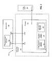
- FIG. 1is a block diagram illustrating a motor drive system, according to an embodiment of the present invention
- FIG. 2is a block diagram illustrating a motor drive controller, according to another embodiment of the present invention.
- FIG. 3is a graph illustrating inverter switching frequency versus motor speed, according to an embodiment of the present invention.
- FIG. 4is a flow diagram illustrating a method for managing processor execution time utilizing variable frequency switching, according to an embodiment of the present invention.
- connectionmeans a direct connection between components or devices that are connected without any intermediate devices.
- coupledmeans either a direct connection between components or devices that are connected, or an indirect connection through one or more passive or active intermediary devices.
- FIG. 1is a block diagram illustrating a motor drive system 100 including motor drive controller 110 and power inverter 150 .
- Controller 110includes processor 120 .
- Motor drive system 100may include additional components not relevant to the present discussion.
- Motor drive controller 110is a composite assembly that provides motor control functions, such as, for example motor sensing, speed estimation, rotor location information, and motor drive control.
- Motor drive controller 110is any suitable device capable of providing motor control functions.
- Motor drive controller 110typically includes a microcontroller, a processor, a combination of a microcontroller and processor, software modules for performing motor control functions, and volatile or non-volatile memory.
- Motor drive controller 110may include additional components not relevant to the present discussion.
- Processor 120produces a pulse-width modulated control signal that is applied to a power inverter 150 .
- Processor 120is coupled to motor drive controller 110 .
- Processor 120includes a control output terminal (CTL 1 ).
- CTL 1control output terminal
- Processor 120may include additional components or terminals not relevant to the present discussion.
- Processor 120is capable of processing different algorithms at different clock rates, for example based on an inverter switching frequency.
- Processor 120may be implemented as any suitable processor or digital signal processor, such as, for example a 40 megahertz (MH) Black Oak processor available from Motorola, Inc. of Schaumburg, Ill.
- MH40 megahertz
- Sensorless control algorithm 130is a software application that estimates rotor position during high-speed and low-speed operations.
- Sensorless control algorithm 130is in communication with processor 120 .
- Sensorless control algorithm 130includes back electromotive force (EMF) algorithm 132 and high frequency injection (HFI) algorithm 135 .
- Sensorless control algorithm 130may additionally include other algorithms for estimating rotor position not listed.
- sensorless control algorithm 130is located within memory included in processor 120 .
- sensorless control algorithm 130is located within memory located elsewhere within motor drive controller 110 circuitry.
- Sensorless control algorithm 130allows processor 120 to compute motor shaft position at any speed using machine terminal information, such as, for example machine terminal voltage information or machine terminal current information.
- Back electromotive force (EMF) algorithm 132is a software application that estimates rotor position during high-speed operations.
- back EMF algorithm 132is located within memory included in processor 120 .
- back EMF algorithm 132is located within memory located elsewhere within motor drive controller 110 circuitry.
- Back EMF algorithm 132allows processor 120 to compute motor shaft position at high speeds using machine terminal information, such as, for example machine terminal voltage information or machine terminal current information. Techniques for utilizing back EMF to compute motor shaft position at high speeds are known in the art and will not be discussed further.
- High frequency injection (HFI) algorithm 135is a software application that estimates rotor position during low-speed operations.
- HFI algorithm 135is located within memory included in processor 120 .
- HFI algorithm 135is located within memory located elsewhere within motor drive controller 110 circuitry.
- HFI algorithm 135allows processor 120 to compute motor shaft position at low speeds using machine terminal information, such as, for example machine terminal voltage information or machine terminal current information. Techniques for utilizing HFI to compute motor shaft position at low speeds are known in the art and will not be discussed further.
- Processor control algorithm 140is a software application that provides a set of routines that allows processor 120 to interface with various hardware devices as well as control internal processing within processor 120 .
- Processor control algorithm 140is executed by processor 120 .
- Processor control algorithm 140provides processor 120 with an inverter switching frequency that determines processor execution time of processor 120 .
- processor control algorithm 140is located within memory included in processor 120 .
- processor control algorithm 140is located within memory located elsewhere within motor drive controller 110 circuitry.
- processor control algorithm 140is located elsewhere within motor drive system 100 .
- Processor control algorithm 140may be implemented as a stand alone algorithm or as part of a larger algorithm, such as, for example as part of a basic input/output system (BIOS) or as part of an operating system (OS). In one embodiment, processor control algorithm 140 modifies the rate at which processor 120 interrupts other processing to process instructions related to sensorless control algorithm 130 .
- BIOSbasic input/output system
- OSoperating system
- Power inverter 150includes a control input terminal (CTL 2 ). In one embodiment, control input terminal (CTL 2 ) of power inverter 150 is coupled to control output terminal (CTL 1 ) of processor 120 . Power inverter 150 is in communication with processor 120 . In another embodiment, control input terminal (CTL 2 ) of power inverter 150 is coupled to motor drive controller 110 , and power inverter 150 is in communication with processor 120 via motor drive controller 110 . Power inverter 150 may include additional components or terminals not relevant to the present discussion. Power inverter 150 provides a pulse-width modulated (PWM) power signal to the motor (not shown) based on a pulse-width modulated control signal received from processor 120 .
- PWMpulse-width modulated
- processor 120receives machine terminal information and computes motor shaft position based on an estimation of rotor position utilizing sensorless control algorithm 130 .
- Estimation of rotor positionprovides a means for determination of motor speed.
- EMFback electromotive force
- estimation of rotor positionis conducted utilizing back electromotive force (EMF) algorithm 132 .
- EMFback electromotive force
- estimation of rotor positionis conducted utilizing high frequency injection (HFI) algorithm 135 in addition to EMF algorithm 132 .
- HFIhigh frequency injection
- processor 120instructs processor control algorithm 140 to increase processor execution time by decreasing inverter switching frequency provided to processor 120 .
- HFIhigh frequency injection
- processor 120instructs processor control algorithm 140 to decrease processor execution time by increasing inverter switching frequency provided to processor 120 .
- the choice of switching frequenciescan be modified by system considerations including power losses, audible noise, and peak ripple current.
- FIG. 2is a block diagram illustrating a motor drive system 200 including motor drive controller 110 , power inverter 150 , and microprocessor 225 .
- Controller 210includes processor 220 .
- Processor 220includes sensorless control algorithm 130 .
- Sensorless control algorithm 130includes back electromotive force (EMF) algorithm 132 and high frequency injection algorithm 135 .
- Microprocessor 225includes processor control algorithm 240 .
- Identically named and numbered components from FIG. 1function as described above.
- Motor drive system 200may include additional components not relevant to the present discussion.
- Processor 220further includes a control output terminal (CTL 1 ), a communication output terminal (COM 1 ), and a clock input terminal (CLK 1 ). In another embodiment, the functionality of communication output terminal (COM 1 ) and clock input terminal (CLK 1 ) of processor 220 are performed by a single signal input/output terminal. Processor 220 may include additional components or terminals not relevant to the present discussion. Processor 220 is capable of processing different algorithms at different clock rates, for example based on an inverter switching frequency. Processor 220 may be implemented as any suitable processor, such as, for example a 40 megahertz (MH) Black Oak processor available from Motorola, Inc. of Schaumburg, Ill.
- MH40 megahertz
- Microprocessor 225further includes a communication input terminal (COM 2 ) and a clock output terminal (CLK 2 ). In another embodiment, the functionality of communication input terminal (COM 2 ) and clock output terminal (CLK 2 ) of microprocessor 225 are performed by a single signal input/output terminal. Communication output terminal (COM 1 ) of processor 220 is coupled to communication input terminal (COM 2 ) of microprocessor 225 , and clock input terminal (CLK 1 ) of processor 220 is coupled to clock output terminal (CLK 2 ) of microprocessor 225 .
- Microprocessor 225may include additional components or terminals not relevant to the present discussion. Microprocessor 225 may be implemented as any suitable microprocessor.
- Processor control algorithm 240is a software application that provides a set of routines that allows microprocessor 225 to interface with various hardware devices.
- Processor control algorithm 240is in communication with processor 220 and provides processor 220 with an inverter switching frequency that determines processor execution time of processor 220 .
- processor control algorithm 240is located within memory included in microprocessor 225 .
- Processor control algorithm 240may be implemented as a stand alone algorithm or as part of a larger algorithm, such as, for example as part of a basic input/output system (BIOS) or as part of an operating system (OS).
- BIOSbasic input/output system
- OSoperating system
- processor 220receives machine terminal information and computes motor shaft position based on an estimation of rotor position utilizing sensorless control algorithm 130 .
- Estimation of rotor positionprovides a means for determination of motor speed.
- EMFback electromotive force
- estimation of rotor positionis conducted utilizing high frequency injection (HFI) algorithm 135 in addition to EMF algorithm 132 .
- processor 220instructs processor control algorithm 240 within microprocessor 225 to increase processor execution time of processor 220 by decreasing inverter switching frequency provided to processor 220 .
- processor 220instructs processor control algorithm 240 within microprocessor 225 to decrease processor execution time of processor 220 by increasing inverter switching frequency provided to processor 220 .
- the choice of switching frequenciesis determined by system considerations including power losses, audible noise, peak ripple current, and the like.
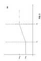
- FIG. 3is a graph illustrating inverter switching frequency versus motor speed.
- the x-axisrepresents absolute motor speed and the y-axis represents inverter switching frequency.
- the y-axisrepresents an inverter switching frequency supplied to a processor ( 120 , 130 ) by a processor control algorithm ( 140 , 240 ) based on a motor speed determination utilizing sensorless control algorithm 130 .
- FIG. 3additionally includes motor speeds (S 1 and S 2 ) and associated inverter switching frequencies (Freq 1 and Freq 2 ) provided for illustrative purposes.
- Motor speeds (S 1 and S 2 )define three regions. In one embodiment, one region is defined as including motor speeds that are less than motor speed S 1 . A second region is defined as including motor speeds that lie between motor speeds (S 1 and S 2 ). A third region is defined as including motor speeds that are greater than motor speed S 2 . In this embodiment, each motor speed region has a corresponding frequency or range of frequencies associated with it. In other embodiments, the graph may include non-linear portions within one or more regions, such as, for example within the second region that includes motor speeds that lie between motor speeds (S 1 and S 2 ).
- inverter switching frequency Freq 2is provided to the processor.
- inverter switching frequency Freq 1is provided to the processor.
- a variable inverter switching frequencyis provided to the processor based on the slope of the line between motor speeds (S 1 and S 2 ).
- inverter switching frequency Freq 2is provided to the processor.
- an inverter switching frequency of 10 kilohertz (KHz)is provided to the processor.
- the 10 kHz inverter switching frequencyallows the processor to perform all calculations within 100 microseconds ( ⁇ S) when synchronous pulse-width modulation (PWM) is used.
- inverter switching frequency Freq 1is provided to the processor.
- EMFback electromotive force
- HFIhigh frequency injection
- inverter switching frequencyFreq 1 is provided to the processor.
- an inverter switching frequency of 5 kilohertz (KHz)is provided to the processor.
- KHz5 kilohertz
- the 5 kHz inverter switching frequencyallows the processor to perform all calculations within 200 microseconds ( ⁇ S) when synchronous pulse-width modulation (PWM) is used.
- PWMsynchronous pulse-width modulation
- the additional processing timeallows the processor to execute both algorithms (back EMF and HFI).
- the HFI algorithmWhen the processor receives machine terminal information and determines a motor speed that lies in the region defined between motor speeds (S 1 and S 2 ), the HFI algorithm is deactivated and an inverter switching frequency is determined based on the slope of the line between motor speeds (S 1 and S 2 ). In an example, when the determines a motor speed that lies in the region defined between motor speeds (S 1 and S 2 ), the HFI algorithm is deactivated and an inverter switching frequency between 5 KHz and 10 KHz is provided to the processor.
- FIG. 4is a flow diagram depicting an exemplary embodiment of code on a computer readable medium in accordance with the present invention.
- FIG. 4details an embodiment of a method 400 for managing processor execution time utilizing variable frequency switching.
- Method 400may utilize one or more concepts detailed in FIGS. 1–3 , above.
- Method 400begins at block 410 .
- motor speed datais received.
- a processorreceives machine terminal information and determines motor speed data based on the machine terminal information.
- processor 120receives machine terminal current or machine terminal voltage and determines motor speed data based on the received machine terminal information.
- a processorreceives machine terminal information and processes the motor speed data utilizing a back electromotive force (EMF) method or a combination of the EMF method and a high frequency injection method.
- EMFback electromotive force
- the received motor speed datais compared to predetermined motor speed ranges.
- the predetermined motor speed rangesare defined by specific motor speeds.
- the motor speedsare manufacturer determined motor speeds.
- the motor speed rangesare manufacturer determined motor speed ranges.
- a motor speed range that includes the motor speed datais determined based on the comparison in block 430 . In one embodiment, the motor speed range is determined as described in FIG. 3 above.
- inverter switching frequencyis modulated based on the determined motor speed range of block 440 .
- the inverter switching frequencyis modulated by determining a modified inverter switching frequency value based on the determined motor speed range and providing the modified inverter switching frequency value to a processor control algorithm.
- a processor control algorithmmodifies the inverter switching frequency based on the modified inverter switching frequency value.
- the processor control algorithmmay be implemented as an operating system or as a BIOS.
- modulating the inverter switching frequency of the processorincludes assigning a first inverter switching frequency when the received motor speed data is within a first motor speed range, providing a variable inverter switching frequency when the received motor speed data is within a second motor speed range, and providing a second inverter switching frequency when the received motor speed data is within a second motor speed range. Determining the inverter switching frequency may also include system considerations, such as, for example power losses, audible noise, peak ripple current, and the like. The above method allows the use of lower cost processors and may provide growth for additional software features.
- the above-described system and method for managing processor execution time in a motor controlleris an example system and method.
- the system and method for managing processor execution time in a motor controllerillustrates one possible approach for managing processor execution time in a motor controller.
- the actual implementationmay vary from the package discussed.
- various other improvements and modifications to this inventionmay occur to those skilled in the art, and those improvements and modifications will fall within the scope of this invention as set forth in the claims below.
Landscapes
- Engineering & Computer Science (AREA)
- Power Engineering (AREA)
- Control Of Ac Motors In General (AREA)
- Control Of Motors That Do Not Use Commutators (AREA)
Abstract
Description
Freq={[(S−S1)/(S2−S1)]*Freq1}+Freq1
where S is a motor speed between motor speeds (S1and S2).
Claims (9)
Priority Applications (1)
| Application Number | Priority Date | Filing Date | Title |
|---|---|---|---|
| US10/676,529US6979968B2 (en) | 2003-10-01 | 2003-10-01 | Method and system for managing processor execution time utilizing variable frequency switching |
Applications Claiming Priority (1)
| Application Number | Priority Date | Filing Date | Title |
|---|---|---|---|
| US10/676,529US6979968B2 (en) | 2003-10-01 | 2003-10-01 | Method and system for managing processor execution time utilizing variable frequency switching |
Publications (2)
| Publication Number | Publication Date |
|---|---|
| US20050073272A1 US20050073272A1 (en) | 2005-04-07 |
| US6979968B2true US6979968B2 (en) | 2005-12-27 |
Family
ID=34393597
Family Applications (1)
| Application Number | Title | Priority Date | Filing Date |
|---|---|---|---|
| US10/676,529Expired - LifetimeUS6979968B2 (en) | 2003-10-01 | 2003-10-01 | Method and system for managing processor execution time utilizing variable frequency switching |
Country Status (1)
| Country | Link |
|---|---|
| US (1) | US6979968B2 (en) |
Cited By (4)
| Publication number | Priority date | Publication date | Assignee | Title |
|---|---|---|---|---|
| US20090107742A1 (en)* | 2007-10-24 | 2009-04-30 | Gm Global Technology Operations, Inc. | Method and system for controlling a power inverter in electric drives of vehicles with two-mode transmissions |
| US20100007300A1 (en)* | 2008-07-09 | 2010-01-14 | Caterpillar Inc. | Method and system for temperature-based power converter control |
| US11171586B2 (en) | 2019-04-25 | 2021-11-09 | Black & Decker Inc. | Low-speed sensorless brushless motor control in a power tool |
| US11374520B2 (en) | 2019-06-10 | 2022-06-28 | Black & Decker Inc. | Field-oriented sensorless brushless motor control in a power tool |
Families Citing this family (4)
| Publication number | Priority date | Publication date | Assignee | Title |
|---|---|---|---|---|
| US7652443B2 (en)* | 2007-10-24 | 2010-01-26 | Gm Global Technology Operations, Inc. | Method and system for controlling a power inverter in electric drives |
| FI121307B (en)* | 2008-04-07 | 2010-09-30 | Kone Corp | Power supply unit and power supply arrangement |
| CN104379654A (en) | 2012-04-30 | 2015-02-25 | 普莱斯提派克包装公司 | Oxygen scavenging compositions |
| US11338983B2 (en) | 2014-08-22 | 2022-05-24 | Plastipak Packaging, Inc. | Oxygen scavenging compositions, articles containing same, and methods of their use |
Citations (13)
| Publication number | Priority date | Publication date | Assignee | Title |
|---|---|---|---|---|
| US4847555A (en)* | 1986-12-05 | 1989-07-11 | Heidelberger Druckmaschinen Ag | Device for detecting rotational speed of a motor using first and second sensors and a switching unit to select between the two sensors |
| US4880474A (en)* | 1986-10-08 | 1989-11-14 | Hitachi, Ltd. | Method and apparatus for operating vacuum cleaner |
| US4933608A (en)* | 1988-06-06 | 1990-06-12 | Mitsubishi Denki Kabushiki Kaisha | Method of electrically braking a linear motor |
| US4971522A (en)* | 1989-05-11 | 1990-11-20 | Butlin Duncan M | Control system and method for AC motor driven cyclic load |
| US4983895A (en)* | 1986-10-08 | 1991-01-08 | Hitachi, Ltd. | Method and apparatus for operating vacuum cleaner |
| US5298840A (en)* | 1991-07-15 | 1994-03-29 | Rohm Co., Ltd. | Motor control circuit and motor drive system using the same |
| US5459386A (en)* | 1992-02-13 | 1995-10-17 | Mitsubishi Denki Kabushiki Kaisha | Motor drive control apparatus having a plurality of motor characteristics |
| US5650707A (en)* | 1995-09-28 | 1997-07-22 | Electric Power Research Institute, Inc. | Inverter-controlled induction machine with an extended speed range |
| US20020039010A1 (en)* | 2000-09-29 | 2002-04-04 | Mhe Technologies, Inc. | Material handling system and method of operating the same |
| US20030052643A1 (en)* | 2001-09-14 | 2003-03-20 | Sweo Edwin A. | Brushless doubly-fed induction machine control |
| US20030154041A1 (en)* | 2001-09-05 | 2003-08-14 | Mcgaughey Donald R. | Method to estimate motor speed for stabilized motor control |
| US6654648B2 (en)* | 2000-04-03 | 2003-11-25 | Toyota Jidosha Kabushiki Kaisha | Technique of monitoring abnormality in plurality of CPUs or controllers |
| US20040134698A1 (en)* | 2002-12-26 | 2004-07-15 | Fujitsu Limited | Drive control apparatus for hybrid vehicle |
- 2003
- 2003-10-01USUS10/676,529patent/US6979968B2/ennot_activeExpired - Lifetime
Patent Citations (19)
| Publication number | Priority date | Publication date | Assignee | Title |
|---|---|---|---|---|
| US4880474A (en)* | 1986-10-08 | 1989-11-14 | Hitachi, Ltd. | Method and apparatus for operating vacuum cleaner |
| US4983895A (en)* | 1986-10-08 | 1991-01-08 | Hitachi, Ltd. | Method and apparatus for operating vacuum cleaner |
| US5075607A (en)* | 1986-10-08 | 1991-12-24 | Hitachi, Ltd. | Method and apparatus for operating vacuum cleaner |
| US5166585A (en)* | 1986-10-08 | 1992-11-24 | Hitachi, Ltd. | Motor control apparatus for an electric vacuum cleaner |
| US5294872A (en)* | 1986-10-08 | 1994-03-15 | Hitachi, Ltd. | Method and apparatus for operating vacuum cleaner |
| US4847555A (en)* | 1986-12-05 | 1989-07-11 | Heidelberger Druckmaschinen Ag | Device for detecting rotational speed of a motor using first and second sensors and a switching unit to select between the two sensors |
| US4933608A (en)* | 1988-06-06 | 1990-06-12 | Mitsubishi Denki Kabushiki Kaisha | Method of electrically braking a linear motor |
| US4971522A (en)* | 1989-05-11 | 1990-11-20 | Butlin Duncan M | Control system and method for AC motor driven cyclic load |
| US5298840A (en)* | 1991-07-15 | 1994-03-29 | Rohm Co., Ltd. | Motor control circuit and motor drive system using the same |
| US5459386A (en)* | 1992-02-13 | 1995-10-17 | Mitsubishi Denki Kabushiki Kaisha | Motor drive control apparatus having a plurality of motor characteristics |
| US5650707A (en)* | 1995-09-28 | 1997-07-22 | Electric Power Research Institute, Inc. | Inverter-controlled induction machine with an extended speed range |
| US6654648B2 (en)* | 2000-04-03 | 2003-11-25 | Toyota Jidosha Kabushiki Kaisha | Technique of monitoring abnormality in plurality of CPUs or controllers |
| US20020039010A1 (en)* | 2000-09-29 | 2002-04-04 | Mhe Technologies, Inc. | Material handling system and method of operating the same |
| US6720751B2 (en)* | 2000-09-29 | 2004-04-13 | Mhe Technologies, Inc. | Material handling system and method of operating the same |
| US20030154041A1 (en)* | 2001-09-05 | 2003-08-14 | Mcgaughey Donald R. | Method to estimate motor speed for stabilized motor control |
| US6708134B2 (en)* | 2001-09-05 | 2004-03-16 | Her Majesty The Queen In Right Of Canada, As Represented By The Minister Of National Defence | Method to estimate motor speed for stabilized motor control |
| US20030052643A1 (en)* | 2001-09-14 | 2003-03-20 | Sweo Edwin A. | Brushless doubly-fed induction machine control |
| US6784634B2 (en)* | 2001-09-14 | 2004-08-31 | Edwin A. Sweo | Brushless doubly-fed induction machine control |
| US20040134698A1 (en)* | 2002-12-26 | 2004-07-15 | Fujitsu Limited | Drive control apparatus for hybrid vehicle |
Cited By (10)
| Publication number | Priority date | Publication date | Assignee | Title |
|---|---|---|---|---|
| US20090107742A1 (en)* | 2007-10-24 | 2009-04-30 | Gm Global Technology Operations, Inc. | Method and system for controlling a power inverter in electric drives of vehicles with two-mode transmissions |
| US8165737B2 (en)* | 2007-10-24 | 2012-04-24 | GM Global Technology Operations LLC | Method and system for controlling a power inverter in electric drives of vehicles with two-mode transmissions |
| US20100007300A1 (en)* | 2008-07-09 | 2010-01-14 | Caterpillar Inc. | Method and system for temperature-based power converter control |
| US8242735B2 (en)* | 2008-07-09 | 2012-08-14 | Caterpillar Inc. | Method and system for temperature-based power converter control |
| US11171586B2 (en) | 2019-04-25 | 2021-11-09 | Black & Decker Inc. | Low-speed sensorless brushless motor control in a power tool |
| US11303235B2 (en) | 2019-04-25 | 2022-04-12 | Black & Decker Inc. | Dual-controller system for a sensorless brushless motor control |
| US11374514B2 (en) | 2019-04-25 | 2022-06-28 | Black & Decker Inc. | Sensorless variable conduction control for brushless motor |
| US11374520B2 (en) | 2019-06-10 | 2022-06-28 | Black & Decker Inc. | Field-oriented sensorless brushless motor control in a power tool |
| US11374519B2 (en) | 2019-06-10 | 2022-06-28 | Black & Decker Inc. | Field-oriented sensorless brushless motor control in a power tool |
| US11469697B2 (en) | 2019-06-10 | 2022-10-11 | Black & Decker Inc. | Field-oriented sensorless brushless motor control in a power tool |
Also Published As
| Publication number | Publication date |
|---|---|
| US20050073272A1 (en) | 2005-04-07 |
Similar Documents
| Publication | Publication Date | Title |
|---|---|---|
| JP3695342B2 (en) | Electric motor control device | |
| US10608576B2 (en) | Motor control apparatus | |
| EP1965490B1 (en) | Apparatus and method for driving synchronous motor | |
| US6501243B1 (en) | Synchronous motor-control apparatus and vehicle using the control apparatus | |
| US8159162B2 (en) | Motor control apparatus, vehicle fan drive apparatus, and motor control method | |
| US5934398A (en) | Electric vehicle motor control apparatus | |
| EP3002872B1 (en) | Methods of estimating rotor magnet temperature and systems thereof | |
| JP3146791B2 (en) | Drive control device for permanent magnet type synchronous motor | |
| JP2003199389A (en) | Motor control device and control method thereof | |
| CN110086382B (en) | Control method of brushless direct current motor, computer device and readable storage medium | |
| US6979968B2 (en) | Method and system for managing processor execution time utilizing variable frequency switching | |
| CN110880897A (en) | Motor control method and device and driving device | |
| JP2010045941A (en) | Motor control circuit, fan driver for vehicle and motor control method | |
| JP2003041966A (en) | Hybrid vehicle control device | |
| WO2006088454A1 (en) | Method and system for managing processor execution time utilizing variable frequency switching | |
| US8269437B2 (en) | Rotary electric machine control system | |
| US6690135B2 (en) | Method for compensating for dead time non-linearities in a pulse width modulation controlled switching scheme | |
| JP2011125154A (en) | Demagnetization determining system of rotating electric machine | |
| JP4140304B2 (en) | Motor control device | |
| CN116582050A (en) | Starting method and device of non-inductive FOC control mode and electronic equipment | |
| JP7584656B2 (en) | Motor control method and motor control device | |
| JP7632197B2 (en) | INVERTER CONTROL DEVICE, PROGRAM, AND INVERTER CONTROL METHOD | |
| US11239782B2 (en) | Control system for a sensor-free electric motor | |
| CN115540262A (en) | Control method of air conditioner, air conditioner and computer storage medium | |
| JP2021533721A (en) | AC motor control device and control method |
Legal Events
| Date | Code | Title | Description |
|---|---|---|---|
| AS | Assignment | Owner name:GENERAL MOTORS CORPORATION, MICHIGAN Free format text:ASSIGNMENT OF ASSIGNORS INTEREST;ASSIGNORS:NAGASHIMA, JAMES M.;OMEARA, THOMAS P.;PATEL, NITINKUMAR R.;AND OTHERS;REEL/FRAME:014244/0132;SIGNING DATES FROM 20030805 TO 20030807 | |
| STCF | Information on status: patent grant | Free format text:PATENTED CASE | |
| AS | Assignment | Owner name:GM GLOBAL TECHNOLOGY OPERATIONS, INC., MICHIGAN Free format text:ASSIGNMENT OF ASSIGNORS INTEREST;ASSIGNOR:GENERAL MOTORS CORPORATION;REEL/FRAME:022092/0703 Effective date:20050119 Owner name:GM GLOBAL TECHNOLOGY OPERATIONS, INC.,MICHIGAN Free format text:ASSIGNMENT OF ASSIGNORS INTEREST;ASSIGNOR:GENERAL MOTORS CORPORATION;REEL/FRAME:022092/0703 Effective date:20050119 | |
| AS | Assignment | Owner name:UNITED STATES DEPARTMENT OF THE TREASURY, DISTRICT Free format text:SECURITY AGREEMENT;ASSIGNOR:GM GLOBAL TECHNOLOGY OPERATIONS, INC.;REEL/FRAME:022201/0547 Effective date:20081231 Owner name:UNITED STATES DEPARTMENT OF THE TREASURY,DISTRICT Free format text:SECURITY AGREEMENT;ASSIGNOR:GM GLOBAL TECHNOLOGY OPERATIONS, INC.;REEL/FRAME:022201/0547 Effective date:20081231 | |
| AS | Assignment | Owner name:CITICORP USA, INC. AS AGENT FOR BANK PRIORITY SECU Free format text:SECURITY AGREEMENT;ASSIGNOR:GM GLOBAL TECHNOLOGY OPERATIONS, INC.;REEL/FRAME:022553/0399 Effective date:20090409 Owner name:CITICORP USA, INC. AS AGENT FOR HEDGE PRIORITY SEC Free format text:SECURITY AGREEMENT;ASSIGNOR:GM GLOBAL TECHNOLOGY OPERATIONS, INC.;REEL/FRAME:022553/0399 Effective date:20090409 | |
| FPAY | Fee payment | Year of fee payment:4 | |
| AS | Assignment | Owner name:GM GLOBAL TECHNOLOGY OPERATIONS, INC., MICHIGAN Free format text:RELEASE BY SECURED PARTY;ASSIGNOR:UNITED STATES DEPARTMENT OF THE TREASURY;REEL/FRAME:023124/0470 Effective date:20090709 Owner name:GM GLOBAL TECHNOLOGY OPERATIONS, INC.,MICHIGAN Free format text:RELEASE BY SECURED PARTY;ASSIGNOR:UNITED STATES DEPARTMENT OF THE TREASURY;REEL/FRAME:023124/0470 Effective date:20090709 | |
| AS | Assignment | Owner name:GM GLOBAL TECHNOLOGY OPERATIONS, INC., MICHIGAN Free format text:RELEASE BY SECURED PARTY;ASSIGNORS:CITICORP USA, INC. AS AGENT FOR BANK PRIORITY SECURED PARTIES;CITICORP USA, INC. AS AGENT FOR HEDGE PRIORITY SECURED PARTIES;REEL/FRAME:023127/0273 Effective date:20090814 Owner name:GM GLOBAL TECHNOLOGY OPERATIONS, INC.,MICHIGAN Free format text:RELEASE BY SECURED PARTY;ASSIGNORS:CITICORP USA, INC. AS AGENT FOR BANK PRIORITY SECURED PARTIES;CITICORP USA, INC. AS AGENT FOR HEDGE PRIORITY SECURED PARTIES;REEL/FRAME:023127/0273 Effective date:20090814 | |
| AS | Assignment | Owner name:UNITED STATES DEPARTMENT OF THE TREASURY, DISTRICT Free format text:SECURITY AGREEMENT;ASSIGNOR:GM GLOBAL TECHNOLOGY OPERATIONS, INC.;REEL/FRAME:023156/0001 Effective date:20090710 Owner name:UNITED STATES DEPARTMENT OF THE TREASURY,DISTRICT Free format text:SECURITY AGREEMENT;ASSIGNOR:GM GLOBAL TECHNOLOGY OPERATIONS, INC.;REEL/FRAME:023156/0001 Effective date:20090710 | |
| AS | Assignment | Owner name:UAW RETIREE MEDICAL BENEFITS TRUST, MICHIGAN Free format text:SECURITY AGREEMENT;ASSIGNOR:GM GLOBAL TECHNOLOGY OPERATIONS, INC.;REEL/FRAME:023161/0911 Effective date:20090710 Owner name:UAW RETIREE MEDICAL BENEFITS TRUST,MICHIGAN Free format text:SECURITY AGREEMENT;ASSIGNOR:GM GLOBAL TECHNOLOGY OPERATIONS, INC.;REEL/FRAME:023161/0911 Effective date:20090710 | |
| AS | Assignment | Owner name:GM GLOBAL TECHNOLOGY OPERATIONS, INC., MICHIGAN Free format text:RELEASE BY SECURED PARTY;ASSIGNOR:UNITED STATES DEPARTMENT OF THE TREASURY;REEL/FRAME:025245/0347 Effective date:20100420 Owner name:GM GLOBAL TECHNOLOGY OPERATIONS, INC., MICHIGAN Free format text:RELEASE BY SECURED PARTY;ASSIGNOR:UAW RETIREE MEDICAL BENEFITS TRUST;REEL/FRAME:025311/0725 Effective date:20101026 | |
| AS | Assignment | Owner name:WILMINGTON TRUST COMPANY, DELAWARE Free format text:SECURITY AGREEMENT;ASSIGNOR:GM GLOBAL TECHNOLOGY OPERATIONS, INC.;REEL/FRAME:025327/0262 Effective date:20101027 | |
| AS | Assignment | Owner name:GM GLOBAL TECHNOLOGY OPERATIONS LLC, MICHIGAN Free format text:CHANGE OF NAME;ASSIGNOR:GM GLOBAL TECHNOLOGY OPERATIONS, INC.;REEL/FRAME:025780/0902 Effective date:20101202 | |
| FPAY | Fee payment | Year of fee payment:8 | |
| AS | Assignment | Owner name:GM GLOBAL TECHNOLOGY OPERATIONS LLC, MICHIGAN Free format text:RELEASE BY SECURED PARTY;ASSIGNOR:WILMINGTON TRUST COMPANY;REEL/FRAME:034371/0676 Effective date:20141017 | |
| FPAY | Fee payment | Year of fee payment:12 |