US6979309B2 - Systems and methods for performing blood processing and/or fluid exchange procedures - Google Patents
Systems and methods for performing blood processing and/or fluid exchange proceduresDownload PDFInfo
- Publication number
- US6979309B2 US6979309B2US10/041,949US4194902AUS6979309B2US 6979309 B2US6979309 B2US 6979309B2US 4194902 AUS4194902 AUS 4194902AUS 6979309 B2US6979309 B2US 6979309B2
- Authority
- US
- United States
- Prior art keywords
- fluid
- machine
- waste
- blood
- replacement
- Prior art date
- Legal status (The legal status is an assumption and is not a legal conclusion. Google has not performed a legal analysis and makes no representation as to the accuracy of the status listed.)
- Expired - Fee Related, expires
Links
- 239000012530fluidSubstances0.000titleclaimsabstractdescription338
- 238000000034methodMethods0.000titleclaimsdescription36
- 239000008280bloodSubstances0.000titleabstractdescription83
- 210000004369bloodAnatomy0.000titleabstractdescription81
- 238000012545processingMethods0.000titledescription54
- 230000007246mechanismEffects0.000claimsdescription14
- 230000008569processEffects0.000claimsdescription7
- 230000001360synchronised effectEffects0.000claimsdescription7
- 238000006073displacement reactionMethods0.000claims3
- 239000002699waste materialSubstances0.000abstractdescription139
- 238000011282treatmentMethods0.000abstractdescription50
- 238000002615hemofiltrationMethods0.000description57
- 230000006870functionEffects0.000description34
- 238000000108ultra-filtrationMethods0.000description33
- 230000017531blood circulationEffects0.000description27
- 238000001631haemodialysisMethods0.000description16
- 230000000322hemodialysisEffects0.000description16
- 238000007726management methodMethods0.000description16
- 230000004872arterial blood pressureEffects0.000description13
- 239000012528membraneSubstances0.000description13
- 238000011277treatment modalityMethods0.000description13
- 238000001914filtrationMethods0.000description9
- 230000008859changeEffects0.000description8
- 238000005534hematocritMethods0.000description8
- 238000012544monitoring processMethods0.000description8
- 230000037452primingEffects0.000description8
- 230000008321arterial blood flowEffects0.000description7
- 230000009977dual effectEffects0.000description7
- 230000033001locomotionEffects0.000description7
- 230000000712assemblyEffects0.000description6
- 238000000429assemblyMethods0.000description6
- 230000007423decreaseEffects0.000description6
- 238000000502dialysisMethods0.000description6
- 239000000385dialysis solutionSubstances0.000description6
- 239000000463materialSubstances0.000description6
- 230000001225therapeutic effectEffects0.000description6
- 230000001413cellular effectEffects0.000description5
- 238000011144upstream manufacturingMethods0.000description5
- 238000007373indentationMethods0.000description4
- 238000012423maintenanceMethods0.000description4
- 238000002203pretreatmentMethods0.000description4
- 230000002441reversible effectEffects0.000description4
- 239000002441uremic toxinSubstances0.000description4
- 238000011109contaminationMethods0.000description3
- 239000004033plasticSubstances0.000description3
- 229920003023plasticPolymers0.000description3
- 238000012360testing methodMethods0.000description3
- 238000002560therapeutic procedureMethods0.000description3
- 230000005540biological transmissionEffects0.000description2
- 239000012503blood componentSubstances0.000description2
- 230000036770blood supplyEffects0.000description2
- 238000004891communicationMethods0.000description2
- 239000000306componentSubstances0.000description2
- 238000007596consolidation processMethods0.000description2
- 230000003247decreasing effectEffects0.000description2
- 239000000835fiberSubstances0.000description2
- 230000003287optical effectEffects0.000description2
- 238000005457optimizationMethods0.000description2
- 230000002572peristaltic effectEffects0.000description2
- 230000009467reductionEffects0.000description2
- 238000012795verificationMethods0.000description2
- 206010053567CoagulopathiesDiseases0.000description1
- LFQSCWFLJHTTHZ-UHFFFAOYSA-NEthanolChemical compoundCCOLFQSCWFLJHTTHZ-UHFFFAOYSA-N0.000description1
- 230000005355Hall effectEffects0.000description1
- 208000001953HypotensionDiseases0.000description1
- 239000004793PolystyreneSubstances0.000description1
- 239000008156Ringer's lactate solutionSubstances0.000description1
- XUIMIQQOPSSXEZ-UHFFFAOYSA-NSiliconChemical compound[Si]XUIMIQQOPSSXEZ-UHFFFAOYSA-N0.000description1
- FAPWRFPIFSIZLT-UHFFFAOYSA-MSodium chlorideChemical compound[Na+].[Cl-]FAPWRFPIFSIZLT-UHFFFAOYSA-M0.000description1
- 208000021017Weight GainDiseases0.000description1
- 230000001154acute effectEffects0.000description1
- 239000003146anticoagulant agentSubstances0.000description1
- 229940127219anticoagulant drugDrugs0.000description1
- 238000013459approachMethods0.000description1
- 239000000022bacteriostatic agentSubstances0.000description1
- 239000011324beadSubstances0.000description1
- 230000033228biological regulationEffects0.000description1
- 230000036772blood pressureEffects0.000description1
- 230000001684chronic effectEffects0.000description1
- 230000004087circulationEffects0.000description1
- 230000035602clottingEffects0.000description1
- 239000003086colorantSubstances0.000description1
- 230000001143conditioned effectEffects0.000description1
- 239000000356contaminantSubstances0.000description1
- 230000001351cycling effectEffects0.000description1
- 238000009795derivationMethods0.000description1
- 238000010790dilutionMethods0.000description1
- 239000012895dilutionSubstances0.000description1
- 238000009826distributionMethods0.000description1
- 230000000694effectsEffects0.000description1
- 239000013536elastomeric materialSubstances0.000description1
- 239000003792electrolyteSubstances0.000description1
- 230000008030eliminationEffects0.000description1
- 238000003379elimination reactionMethods0.000description1
- 238000002637fluid replacement therapyMethods0.000description1
- 230000001771impaired effectEffects0.000description1
- 230000003907kidney functionEffects0.000description1
- 239000007788liquidSubstances0.000description1
- 230000013011matingEffects0.000description1
- 238000005259measurementMethods0.000description1
- 239000007769metal materialSubstances0.000description1
- 238000012986modificationMethods0.000description1
- 230000004048modificationEffects0.000description1
- 229920002223polystyrenePolymers0.000description1
- 229920000915polyvinyl chloridePolymers0.000description1
- 239000004800polyvinyl chlorideSubstances0.000description1
- 239000011148porous materialSubstances0.000description1
- 238000003825pressingMethods0.000description1
- 230000008439repair processEffects0.000description1
- 238000000926separation methodMethods0.000description1
- 230000011664signalingEffects0.000description1
- 229910052710siliconInorganic materials0.000description1
- 239000010703siliconSubstances0.000description1
- 239000011780sodium chlorideSubstances0.000description1
- 238000003860storageMethods0.000description1
- 230000001629suppressionEffects0.000description1
- 238000003856thermoformingMethods0.000description1
- 239000003053toxinSubstances0.000description1
- 231100000765toxinToxicity0.000description1
- 108700012359toxinsProteins0.000description1
- 238000012549trainingMethods0.000description1
- 238000012546transferMethods0.000description1
- 230000007704transitionEffects0.000description1
- 238000011269treatment regimenMethods0.000description1
- 230000008320venous blood flowEffects0.000description1
- 230000004584weight gainEffects0.000description1
- 235000019786weight gainNutrition0.000description1
- 230000004580weight lossEffects0.000description1
- 238000003466weldingMethods0.000description1
Images


Classifications
- A—HUMAN NECESSITIES
- A61—MEDICAL OR VETERINARY SCIENCE; HYGIENE
- A61M—DEVICES FOR INTRODUCING MEDIA INTO, OR ONTO, THE BODY; DEVICES FOR TRANSDUCING BODY MEDIA OR FOR TAKING MEDIA FROM THE BODY; DEVICES FOR PRODUCING OR ENDING SLEEP OR STUPOR
- A61M1/00—Suction or pumping devices for medical purposes; Devices for carrying-off, for treatment of, or for carrying-over, body-liquids; Drainage systems
- A61M1/34—Filtering material out of the blood by passing it through a membrane, i.e. hemofiltration or diafiltration
- A—HUMAN NECESSITIES
- A61—MEDICAL OR VETERINARY SCIENCE; HYGIENE
- A61M—DEVICES FOR INTRODUCING MEDIA INTO, OR ONTO, THE BODY; DEVICES FOR TRANSDUCING BODY MEDIA OR FOR TAKING MEDIA FROM THE BODY; DEVICES FOR PRODUCING OR ENDING SLEEP OR STUPOR
- A61M1/00—Suction or pumping devices for medical purposes; Devices for carrying-off, for treatment of, or for carrying-over, body-liquids; Drainage systems
- A61M1/14—Dialysis systems; Artificial kidneys; Blood oxygenators ; Reciprocating systems for treatment of body fluids, e.g. single needle systems for hemofiltration or pheresis
- A61M1/16—Dialysis systems; Artificial kidneys; Blood oxygenators ; Reciprocating systems for treatment of body fluids, e.g. single needle systems for hemofiltration or pheresis with membranes
- A61M1/1601—Control or regulation
- A61M1/1603—Regulation parameters
- A61M1/1611—Weight of the patient
- A—HUMAN NECESSITIES
- A61—MEDICAL OR VETERINARY SCIENCE; HYGIENE
- A61M—DEVICES FOR INTRODUCING MEDIA INTO, OR ONTO, THE BODY; DEVICES FOR TRANSDUCING BODY MEDIA OR FOR TAKING MEDIA FROM THE BODY; DEVICES FOR PRODUCING OR ENDING SLEEP OR STUPOR
- A61M1/00—Suction or pumping devices for medical purposes; Devices for carrying-off, for treatment of, or for carrying-over, body-liquids; Drainage systems
- A61M1/14—Dialysis systems; Artificial kidneys; Blood oxygenators ; Reciprocating systems for treatment of body fluids, e.g. single needle systems for hemofiltration or pheresis
- A61M1/28—Peritoneal dialysis ; Other peritoneal treatment, e.g. oxygenation
- A61M1/282—Operational modes
- A—HUMAN NECESSITIES
- A61—MEDICAL OR VETERINARY SCIENCE; HYGIENE
- A61M—DEVICES FOR INTRODUCING MEDIA INTO, OR ONTO, THE BODY; DEVICES FOR TRANSDUCING BODY MEDIA OR FOR TAKING MEDIA FROM THE BODY; DEVICES FOR PRODUCING OR ENDING SLEEP OR STUPOR
- A61M1/00—Suction or pumping devices for medical purposes; Devices for carrying-off, for treatment of, or for carrying-over, body-liquids; Drainage systems
- A61M1/14—Dialysis systems; Artificial kidneys; Blood oxygenators ; Reciprocating systems for treatment of body fluids, e.g. single needle systems for hemofiltration or pheresis
- A61M1/28—Peritoneal dialysis ; Other peritoneal treatment, e.g. oxygenation
- A61M1/288—Priming
- A—HUMAN NECESSITIES
- A61—MEDICAL OR VETERINARY SCIENCE; HYGIENE
- A61M—DEVICES FOR INTRODUCING MEDIA INTO, OR ONTO, THE BODY; DEVICES FOR TRANSDUCING BODY MEDIA OR FOR TAKING MEDIA FROM THE BODY; DEVICES FOR PRODUCING OR ENDING SLEEP OR STUPOR
- A61M1/00—Suction or pumping devices for medical purposes; Devices for carrying-off, for treatment of, or for carrying-over, body-liquids; Drainage systems
- A61M1/34—Filtering material out of the blood by passing it through a membrane, i.e. hemofiltration or diafiltration
- A61M1/3401—Cassettes therefor
- A—HUMAN NECESSITIES
- A61—MEDICAL OR VETERINARY SCIENCE; HYGIENE
- A61M—DEVICES FOR INTRODUCING MEDIA INTO, OR ONTO, THE BODY; DEVICES FOR TRANSDUCING BODY MEDIA OR FOR TAKING MEDIA FROM THE BODY; DEVICES FOR PRODUCING OR ENDING SLEEP OR STUPOR
- A61M1/00—Suction or pumping devices for medical purposes; Devices for carrying-off, for treatment of, or for carrying-over, body-liquids; Drainage systems
- A61M1/34—Filtering material out of the blood by passing it through a membrane, i.e. hemofiltration or diafiltration
- A61M1/3403—Regulation parameters
- A61M1/341—Regulation parameters by measuring the filtrate rate or volume
- A—HUMAN NECESSITIES
- A61—MEDICAL OR VETERINARY SCIENCE; HYGIENE
- A61M—DEVICES FOR INTRODUCING MEDIA INTO, OR ONTO, THE BODY; DEVICES FOR TRANSDUCING BODY MEDIA OR FOR TAKING MEDIA FROM THE BODY; DEVICES FOR PRODUCING OR ENDING SLEEP OR STUPOR
- A61M1/00—Suction or pumping devices for medical purposes; Devices for carrying-off, for treatment of, or for carrying-over, body-liquids; Drainage systems
- A61M1/34—Filtering material out of the blood by passing it through a membrane, i.e. hemofiltration or diafiltration
- A61M1/342—Adding solutions to the blood, e.g. substitution solutions
- A61M1/3441—Substitution rate control as a function of the ultrafiltration rate
- A61M1/3444—Substitution rate control as a function of the ultrafiltration rate in which the collected ultra-filtrate expels an equal volume of substitution fluid from a reservoir
- A—HUMAN NECESSITIES
- A61—MEDICAL OR VETERINARY SCIENCE; HYGIENE
- A61M—DEVICES FOR INTRODUCING MEDIA INTO, OR ONTO, THE BODY; DEVICES FOR TRANSDUCING BODY MEDIA OR FOR TAKING MEDIA FROM THE BODY; DEVICES FOR PRODUCING OR ENDING SLEEP OR STUPOR
- A61M1/00—Suction or pumping devices for medical purposes; Devices for carrying-off, for treatment of, or for carrying-over, body-liquids; Drainage systems
- A61M1/34—Filtering material out of the blood by passing it through a membrane, i.e. hemofiltration or diafiltration
- A61M1/342—Adding solutions to the blood, e.g. substitution solutions
- A61M1/3441—Substitution rate control as a function of the ultrafiltration rate
- A61M1/3448—Substitution rate control as a function of the ultrafiltration rate by mechanically linked pumps in both ultra-filtrate and substitution flow line
- A—HUMAN NECESSITIES
- A61—MEDICAL OR VETERINARY SCIENCE; HYGIENE
- A61M—DEVICES FOR INTRODUCING MEDIA INTO, OR ONTO, THE BODY; DEVICES FOR TRANSDUCING BODY MEDIA OR FOR TAKING MEDIA FROM THE BODY; DEVICES FOR PRODUCING OR ENDING SLEEP OR STUPOR
- A61M1/00—Suction or pumping devices for medical purposes; Devices for carrying-off, for treatment of, or for carrying-over, body-liquids; Drainage systems
- A61M1/36—Other treatment of blood in a by-pass of the natural circulatory system, e.g. temperature adaptation, irradiation ; Extra-corporeal blood circuits
- A61M1/3607—Regulation parameters
- A61M1/3609—Physical characteristics of the blood, e.g. haematocrit, urea
- A61M1/361—Physical characteristics of the blood, e.g. haematocrit, urea before treatment
- A—HUMAN NECESSITIES
- A61—MEDICAL OR VETERINARY SCIENCE; HYGIENE
- A61M—DEVICES FOR INTRODUCING MEDIA INTO, OR ONTO, THE BODY; DEVICES FOR TRANSDUCING BODY MEDIA OR FOR TAKING MEDIA FROM THE BODY; DEVICES FOR PRODUCING OR ENDING SLEEP OR STUPOR
- A61M1/00—Suction or pumping devices for medical purposes; Devices for carrying-off, for treatment of, or for carrying-over, body-liquids; Drainage systems
- A61M1/36—Other treatment of blood in a by-pass of the natural circulatory system, e.g. temperature adaptation, irradiation ; Extra-corporeal blood circuits
- A61M1/3607—Regulation parameters
- A61M1/3609—Physical characteristics of the blood, e.g. haematocrit, urea
- A61M1/3612—Physical characteristics of the blood, e.g. haematocrit, urea after treatment
- A—HUMAN NECESSITIES
- A61—MEDICAL OR VETERINARY SCIENCE; HYGIENE
- A61M—DEVICES FOR INTRODUCING MEDIA INTO, OR ONTO, THE BODY; DEVICES FOR TRANSDUCING BODY MEDIA OR FOR TAKING MEDIA FROM THE BODY; DEVICES FOR PRODUCING OR ENDING SLEEP OR STUPOR
- A61M1/00—Suction or pumping devices for medical purposes; Devices for carrying-off, for treatment of, or for carrying-over, body-liquids; Drainage systems
- A61M1/36—Other treatment of blood in a by-pass of the natural circulatory system, e.g. temperature adaptation, irradiation ; Extra-corporeal blood circuits
- A61M1/3621—Extra-corporeal blood circuits
- A61M1/3622—Extra-corporeal blood circuits with a cassette forming partially or totally the blood circuit
- A61M1/36224—Extra-corporeal blood circuits with a cassette forming partially or totally the blood circuit with sensing means or components thereof
- A—HUMAN NECESSITIES
- A61—MEDICAL OR VETERINARY SCIENCE; HYGIENE
- A61M—DEVICES FOR INTRODUCING MEDIA INTO, OR ONTO, THE BODY; DEVICES FOR TRANSDUCING BODY MEDIA OR FOR TAKING MEDIA FROM THE BODY; DEVICES FOR PRODUCING OR ENDING SLEEP OR STUPOR
- A61M1/00—Suction or pumping devices for medical purposes; Devices for carrying-off, for treatment of, or for carrying-over, body-liquids; Drainage systems
- A61M1/36—Other treatment of blood in a by-pass of the natural circulatory system, e.g. temperature adaptation, irradiation ; Extra-corporeal blood circuits
- A61M1/3621—Extra-corporeal blood circuits
- A61M1/3622—Extra-corporeal blood circuits with a cassette forming partially or totally the blood circuit
- A61M1/36225—Extra-corporeal blood circuits with a cassette forming partially or totally the blood circuit with blood pumping means or components thereof
- A—HUMAN NECESSITIES
- A61—MEDICAL OR VETERINARY SCIENCE; HYGIENE
- A61M—DEVICES FOR INTRODUCING MEDIA INTO, OR ONTO, THE BODY; DEVICES FOR TRANSDUCING BODY MEDIA OR FOR TAKING MEDIA FROM THE BODY; DEVICES FOR PRODUCING OR ENDING SLEEP OR STUPOR
- A61M1/00—Suction or pumping devices for medical purposes; Devices for carrying-off, for treatment of, or for carrying-over, body-liquids; Drainage systems
- A61M1/36—Other treatment of blood in a by-pass of the natural circulatory system, e.g. temperature adaptation, irradiation ; Extra-corporeal blood circuits
- A61M1/3621—Extra-corporeal blood circuits
- A61M1/3643—Priming, rinsing before or after use
- A61M1/3644—Mode of operation
- A61M1/3646—Expelling the residual body fluid after use, e.g. back to the body
- A—HUMAN NECESSITIES
- A61—MEDICAL OR VETERINARY SCIENCE; HYGIENE
- A61M—DEVICES FOR INTRODUCING MEDIA INTO, OR ONTO, THE BODY; DEVICES FOR TRANSDUCING BODY MEDIA OR FOR TAKING MEDIA FROM THE BODY; DEVICES FOR PRODUCING OR ENDING SLEEP OR STUPOR
- A61M39/00—Tubes, tube connectors, tube couplings, valves, access sites or the like, specially adapted for medical use
- A61M39/02—Access sites
- A61M39/0208—Subcutaneous access sites for injecting or removing fluids
- A—HUMAN NECESSITIES
- A61—MEDICAL OR VETERINARY SCIENCE; HYGIENE
- A61M—DEVICES FOR INTRODUCING MEDIA INTO, OR ONTO, THE BODY; DEVICES FOR TRANSDUCING BODY MEDIA OR FOR TAKING MEDIA FROM THE BODY; DEVICES FOR PRODUCING OR ENDING SLEEP OR STUPOR
- A61M1/00—Suction or pumping devices for medical purposes; Devices for carrying-off, for treatment of, or for carrying-over, body-liquids; Drainage systems
- A61M1/36—Other treatment of blood in a by-pass of the natural circulatory system, e.g. temperature adaptation, irradiation ; Extra-corporeal blood circuits
- A61M1/3621—Extra-corporeal blood circuits
- A61M1/3622—Extra-corporeal blood circuits with a cassette forming partially or totally the blood circuit
- A61M1/36222—Details related to the interface between cassette and machine
- A—HUMAN NECESSITIES
- A61—MEDICAL OR VETERINARY SCIENCE; HYGIENE
- A61M—DEVICES FOR INTRODUCING MEDIA INTO, OR ONTO, THE BODY; DEVICES FOR TRANSDUCING BODY MEDIA OR FOR TAKING MEDIA FROM THE BODY; DEVICES FOR PRODUCING OR ENDING SLEEP OR STUPOR
- A61M1/00—Suction or pumping devices for medical purposes; Devices for carrying-off, for treatment of, or for carrying-over, body-liquids; Drainage systems
- A61M1/36—Other treatment of blood in a by-pass of the natural circulatory system, e.g. temperature adaptation, irradiation ; Extra-corporeal blood circuits
- A61M1/3621—Extra-corporeal blood circuits
- A61M1/3622—Extra-corporeal blood circuits with a cassette forming partially or totally the blood circuit
- A61M1/36226—Constructional details of cassettes, e.g. specific details on material or shape
- A61M1/362262—Details of incorporated reservoirs
- A—HUMAN NECESSITIES
- A61—MEDICAL OR VETERINARY SCIENCE; HYGIENE
- A61M—DEVICES FOR INTRODUCING MEDIA INTO, OR ONTO, THE BODY; DEVICES FOR TRANSDUCING BODY MEDIA OR FOR TAKING MEDIA FROM THE BODY; DEVICES FOR PRODUCING OR ENDING SLEEP OR STUPOR
- A61M1/00—Suction or pumping devices for medical purposes; Devices for carrying-off, for treatment of, or for carrying-over, body-liquids; Drainage systems
- A61M1/36—Other treatment of blood in a by-pass of the natural circulatory system, e.g. temperature adaptation, irradiation ; Extra-corporeal blood circuits
- A61M1/3621—Extra-corporeal blood circuits
- A61M1/3622—Extra-corporeal blood circuits with a cassette forming partially or totally the blood circuit
- A61M1/36226—Constructional details of cassettes, e.g. specific details on material or shape
- A61M1/362265—Details of valves
- A—HUMAN NECESSITIES
- A61—MEDICAL OR VETERINARY SCIENCE; HYGIENE
- A61M—DEVICES FOR INTRODUCING MEDIA INTO, OR ONTO, THE BODY; DEVICES FOR TRANSDUCING BODY MEDIA OR FOR TAKING MEDIA FROM THE BODY; DEVICES FOR PRODUCING OR ENDING SLEEP OR STUPOR
- A61M1/00—Suction or pumping devices for medical purposes; Devices for carrying-off, for treatment of, or for carrying-over, body-liquids; Drainage systems
- A61M1/36—Other treatment of blood in a by-pass of the natural circulatory system, e.g. temperature adaptation, irradiation ; Extra-corporeal blood circuits
- A61M1/3621—Extra-corporeal blood circuits
- A61M1/3626—Gas bubble detectors
- A—HUMAN NECESSITIES
- A61—MEDICAL OR VETERINARY SCIENCE; HYGIENE
- A61M—DEVICES FOR INTRODUCING MEDIA INTO, OR ONTO, THE BODY; DEVICES FOR TRANSDUCING BODY MEDIA OR FOR TAKING MEDIA FROM THE BODY; DEVICES FOR PRODUCING OR ENDING SLEEP OR STUPOR
- A61M1/00—Suction or pumping devices for medical purposes; Devices for carrying-off, for treatment of, or for carrying-over, body-liquids; Drainage systems
- A61M1/36—Other treatment of blood in a by-pass of the natural circulatory system, e.g. temperature adaptation, irradiation ; Extra-corporeal blood circuits
- A61M1/3621—Extra-corporeal blood circuits
- A61M1/3639—Blood pressure control, pressure transducers specially adapted therefor
- A—HUMAN NECESSITIES
- A61—MEDICAL OR VETERINARY SCIENCE; HYGIENE
- A61M—DEVICES FOR INTRODUCING MEDIA INTO, OR ONTO, THE BODY; DEVICES FOR TRANSDUCING BODY MEDIA OR FOR TAKING MEDIA FROM THE BODY; DEVICES FOR PRODUCING OR ENDING SLEEP OR STUPOR
- A61M1/00—Suction or pumping devices for medical purposes; Devices for carrying-off, for treatment of, or for carrying-over, body-liquids; Drainage systems
- A61M1/36—Other treatment of blood in a by-pass of the natural circulatory system, e.g. temperature adaptation, irradiation ; Extra-corporeal blood circuits
- A61M1/3621—Extra-corporeal blood circuits
- A61M1/367—Circuit parts not covered by the preceding subgroups of group A61M1/3621
- A—HUMAN NECESSITIES
- A61—MEDICAL OR VETERINARY SCIENCE; HYGIENE
- A61M—DEVICES FOR INTRODUCING MEDIA INTO, OR ONTO, THE BODY; DEVICES FOR TRANSDUCING BODY MEDIA OR FOR TAKING MEDIA FROM THE BODY; DEVICES FOR PRODUCING OR ENDING SLEEP OR STUPOR
- A61M2205/00—General characteristics of the apparatus
- A61M2205/12—General characteristics of the apparatus with interchangeable cassettes forming partially or totally the fluid circuit
- A61M2205/125—General characteristics of the apparatus with interchangeable cassettes forming partially or totally the fluid circuit with incorporated filters
- A61M2205/126—General characteristics of the apparatus with interchangeable cassettes forming partially or totally the fluid circuit with incorporated filters with incorporated membrane filters
- A—HUMAN NECESSITIES
- A61—MEDICAL OR VETERINARY SCIENCE; HYGIENE
- A61M—DEVICES FOR INTRODUCING MEDIA INTO, OR ONTO, THE BODY; DEVICES FOR TRANSDUCING BODY MEDIA OR FOR TAKING MEDIA FROM THE BODY; DEVICES FOR PRODUCING OR ENDING SLEEP OR STUPOR
- A61M2205/00—General characteristics of the apparatus
- A61M2205/12—General characteristics of the apparatus with interchangeable cassettes forming partially or totally the fluid circuit
- A61M2205/128—General characteristics of the apparatus with interchangeable cassettes forming partially or totally the fluid circuit with incorporated valves
- A—HUMAN NECESSITIES
- A61—MEDICAL OR VETERINARY SCIENCE; HYGIENE
- A61M—DEVICES FOR INTRODUCING MEDIA INTO, OR ONTO, THE BODY; DEVICES FOR TRANSDUCING BODY MEDIA OR FOR TAKING MEDIA FROM THE BODY; DEVICES FOR PRODUCING OR ENDING SLEEP OR STUPOR
- A61M2205/00—General characteristics of the apparatus
- A61M2205/15—Detection of leaks
- A—HUMAN NECESSITIES
- A61—MEDICAL OR VETERINARY SCIENCE; HYGIENE
- A61M—DEVICES FOR INTRODUCING MEDIA INTO, OR ONTO, THE BODY; DEVICES FOR TRANSDUCING BODY MEDIA OR FOR TAKING MEDIA FROM THE BODY; DEVICES FOR PRODUCING OR ENDING SLEEP OR STUPOR
- A61M2205/00—General characteristics of the apparatus
- A61M2205/33—Controlling, regulating or measuring
- A61M2205/3331—Pressure; Flow
- A61M2205/3334—Measuring or controlling the flow rate
- A—HUMAN NECESSITIES
- A61—MEDICAL OR VETERINARY SCIENCE; HYGIENE
- A61M—DEVICES FOR INTRODUCING MEDIA INTO, OR ONTO, THE BODY; DEVICES FOR TRANSDUCING BODY MEDIA OR FOR TAKING MEDIA FROM THE BODY; DEVICES FOR PRODUCING OR ENDING SLEEP OR STUPOR
- A61M2205/00—General characteristics of the apparatus
- A61M2205/33—Controlling, regulating or measuring
- A61M2205/3368—Temperature
- A—HUMAN NECESSITIES
- A61—MEDICAL OR VETERINARY SCIENCE; HYGIENE
- A61M—DEVICES FOR INTRODUCING MEDIA INTO, OR ONTO, THE BODY; DEVICES FOR TRANSDUCING BODY MEDIA OR FOR TAKING MEDIA FROM THE BODY; DEVICES FOR PRODUCING OR ENDING SLEEP OR STUPOR
- A61M2205/00—General characteristics of the apparatus
- A61M2205/33—Controlling, regulating or measuring
- A61M2205/3375—Acoustical, e.g. ultrasonic, measuring means
- A—HUMAN NECESSITIES
- A61—MEDICAL OR VETERINARY SCIENCE; HYGIENE
- A61M—DEVICES FOR INTRODUCING MEDIA INTO, OR ONTO, THE BODY; DEVICES FOR TRANSDUCING BODY MEDIA OR FOR TAKING MEDIA FROM THE BODY; DEVICES FOR PRODUCING OR ENDING SLEEP OR STUPOR
- A61M2205/00—General characteristics of the apparatus
- A61M2205/35—Communication
- A—HUMAN NECESSITIES
- A61—MEDICAL OR VETERINARY SCIENCE; HYGIENE
- A61M—DEVICES FOR INTRODUCING MEDIA INTO, OR ONTO, THE BODY; DEVICES FOR TRANSDUCING BODY MEDIA OR FOR TAKING MEDIA FROM THE BODY; DEVICES FOR PRODUCING OR ENDING SLEEP OR STUPOR
- A61M2205/00—General characteristics of the apparatus
- A61M2205/50—General characteristics of the apparatus with microprocessors or computers
- A61M2205/502—User interfaces, e.g. screens or keyboards
- A61M2205/505—Touch-screens; Virtual keyboard or keypads; Virtual buttons; Soft keys; Mouse touches
- A—HUMAN NECESSITIES
- A61—MEDICAL OR VETERINARY SCIENCE; HYGIENE
- A61M—DEVICES FOR INTRODUCING MEDIA INTO, OR ONTO, THE BODY; DEVICES FOR TRANSDUCING BODY MEDIA OR FOR TAKING MEDIA FROM THE BODY; DEVICES FOR PRODUCING OR ENDING SLEEP OR STUPOR
- A61M2205/00—General characteristics of the apparatus
- A61M2205/60—General characteristics of the apparatus with identification means
- A61M2205/6018—General characteristics of the apparatus with identification means providing set-up signals for the apparatus configuration
- A—HUMAN NECESSITIES
- A61—MEDICAL OR VETERINARY SCIENCE; HYGIENE
- A61M—DEVICES FOR INTRODUCING MEDIA INTO, OR ONTO, THE BODY; DEVICES FOR TRANSDUCING BODY MEDIA OR FOR TAKING MEDIA FROM THE BODY; DEVICES FOR PRODUCING OR ENDING SLEEP OR STUPOR
- A61M2205/00—General characteristics of the apparatus
- A61M2205/60—General characteristics of the apparatus with identification means
- A61M2205/6063—Optical identification systems
- A61M2205/6072—Bar codes
Definitions
- This inventionrelates to systems and methods for processing blood or other fluids that are conveyed to and from an animal body, e.g., for dialysis, filtration, pheresis, or other diagnostic or therapeutic purposes.
- the systemsmay include roller guides on pumps, alignment using pump tubing fitments, air detector tube pushers for loading, blood leak detector, temperature sensing, and pressure sensing.
- HFhemofiltration
- HDhemodialysis
- HDFhemodialysis with hemofiltration
- PDperitoneal dialysis
- a replacement or make-up fluidis returned back to the individual in some proportion to the amount of fluid that is removed from the individual.
- the type and make-up of fluids that these procedures handlevary according to the particular treatment modality being performed, e.g., among waste fluid and replacement fluid (in HF or HDF); or replacement fluid and dialysis solution (in HD or HDF); or fresh peritoneal dialysis solution and spent peritoneal dialysis solution (in PD.
- Controlled balancing of fluid amountscan be achieved by monitoring the weights of fluid removed and replacement or makeup fluid.
- weight sensingitself requires additional fluid circuit elements (e.g., weigh containers), additional hardware elements (e.g., weigh scales), as well as additional processing control and feedback features.
- One aspect of the inventionprovides systems and methods for processing blood and/or other fluids, which include a fluid interface between a fluid processing circuit and a fluid processing machine that makes possible a fast, convenient, one step process for loading the fluid processing circuit on the machine.
- the systems and methodsconsolidate all blood and fluid flow paths in a unitary, easily installed cartridge.
- the cartridgeestablishes a fixed orientation for fluid circuit elements and their operative interface with the hardware elements, such as pumps, sensors, and clamps, on the processing machine.
- the fixed orientationrequires that all safety and control elements on the cartridge and machine are brought into operative association in a single, straightforward loading step. Due to the cartridge, the operator cannot place one part of the fluid circuit into an operating condition with one or more hardware elements on the machine without placing the entire fluid circuit into an operating condition with all the hardware elements on the machine.
- the consolidation of all blood and fluid flow paths in a single, easily installed cartridgealso avoids the potential of contamination, by minimizing the number of connections and disconnections needed during a given treatment session.
- Another aspect of the inventionprovides systems and methods for processing blood and/or other fluids that makes possible the performance of accurate, synchronized volumetric fluid balancing, without the need for weight sensing.
- FIG. 1is a diagrammatic view of a system that includes a machine and fluid processing cartridge that, in use, is mounted on the machine for conducting various types of blood processing and/or fluid exchange procedures;
- FIG. 2is a front perspective view of an embodiment of a machine that can form a part of the system shown in FIG. 1 ;
- FIG. 3is a plane view of the exterior surface of an embodiment of a fluid processing cartridge that can form part of the system shown in FIG. 1 ;
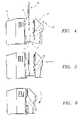
- FIGS. 4 to 6are side elevation views showing the loading of the fluid processing cartridge shown in FIG. 3 onto the machine shown in FIG. 2 ;
- FIG. 7is a perspective exploded view of the fluid processing cartridge shown in FIG. 3 ;
- FIG. 8is a plane view of the exterior surface of the fluid processing cartridge shown in FIG. 3 , with the cover member removed to show the channels that guide the passage of flexible tubing that forms a part of the fluid circuit carried by the cartridge;
- FIG. 9is a plane view of the interior surface of the fluid processing cartridge shown in FIG. 3 ;
- FIGS. 10 and 11are plane view of fluid management modules that form a part of the fluid circuit carried by the cartridge
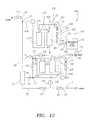
- FIG. 12is a schematic view of a fluid circuit for carrying out hemofiltration, which the cartridge shown in FIG. 3 can be configured to form;
- FIG. 13is a perspective view of the inside of the door of the machine shown in FIG. 2 ;
- FIG. 14is a largely schematic side section view of the overlaying fluid balancing compartments that are part of the fluid management modules shown in FIGS. 10 and 11 , showing their orientation with valve elements carried by on the machine shown in FIG. 2 ;
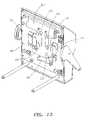
- FIG. 15is a front perspective view of an embodiment of a chassis panel that the machine shown in FIG. 2 can incorporate;
- FIG. 16is a back perspective view of the chassis panel shown in FIG. 15 , showing the mechanical linkage of motors, pumps, and valve elements carried by the chassis panel;
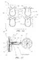
- FIG. 17is a side section view of one of the clamp elements shown in FIGS. 15 and 16 ;
- FIG. 18is a diagrammatic view of a telemetry network that can form a part of the system shown in FIG. 1 ;
- FIG. 19is a plane view of a graphical user interface that the machine shown in FIG. 2 can incorporate.
- FIG. 1shows a system 10 that is well suited for handling fluids in support of various types of blood processing and/or fluid exchange procedures.
- the system 10includes a durable hardware component or machine 16 (see FIG. 2 ) and a removable fluid processing cartridge 18 (see FIG. 3 ) that is intended to be installed in operative association with the machine 16 for use (see FIGS. 4 to 6 ).
- the system 10is suitable for use in many diverse treatment modalities during which blood and/or fluid are conveyed to and from an animal body.
- the system 10is well suited for treatment modalities during which one fluid is removed from the body and replaced with another fluid in a controlled fashion.
- Such modalitiesinclude, e.g., hemofiltration (HF), hemodialysis (HD), hemodialysis with hemofiltration (HDF), and peritoneal dialysis (PD).
- the system 10can perform hemofiltration, e.g., to treat an individual whose renal function is impaired or lacking, according to different selected protocols.
- the system 10can be adapted to perform hemofiltration at relatively high blood flow rates to enable relatively short session time intervals, as well as at lower blood flow rates and over longer session time intervals.
- the former protocolcan be adopted to achieve hemofiltration three or more times a week.
- the latter protocolcan be adapted to achieve an overnight treatment regime, which can be called “nightly hemofiltration.” Nightly hemofiltration can be conducted at intervals less or more frequent than three times a week.
- the system 10can be adapted to perform hemofiltration on an acute basis, or on an intermittent chronic basis, at virtually any prescribed time interval and treatment pattern that achieves the maintenance of uremic toxin levels within a comfortable range.
- the system 10can be adapted to perform multiple hemofiltration treatments per day at varying session times, morning, afternoon, or night, or a combination thereof.
- the system 10can also just as readily be adapted to perform hemodialysis (HD) or hemodialysis with hemofiltration (HDF).
- HDhemodialysis
- HDFhemodialysis with hemofiltration
- the fluid balancing functions that the system 10 can perform, as will be described in greater detail later,can also be readily adapted for use, either individually or in combination, in systems intended to perform prescribed peritoneal dialysis modalities.
- the type and make-up of fluids that the system 10 can balancecan and will vary according to the particular treatment modality being performed, e.g., among waste fluid and replacement fluid (in HF or HDF); or replacement fluid and dialysis solution (in HD or HDF); or fresh peritoneal dialysis solution and spent peritoneal dialysis solution (in PD).
- waste fluid and replacement fluidin HF or HDF
- replacement fluid and dialysis solutionin HD or HDF
- PDfresh peritoneal dialysis solution and spent peritoneal dialysis solution
- the terminology employed in this Specification in characterizing a particular type or make-up of fluid, or as ascribing a source, destination, or direction of fluid flow in the context of describing one treatment modalityis not intended to be interpreted as being limited to that particular type or make up of fluid or that particular flow source, destination, or direction. Rather, a person of skill in the art will readily appreciate that the fluid type and make up and the flow particulars relating to volumetric fluid balancing
- the machine 16(see FIG. 2 ) is preferably lightweight and portable, presenting a compact footprint, suited for operation on a table top or other relatively small surface normally found, e.g., in a hospital room or in a home.
- the compact size of the machine 16also makes it well suited for shipment to a remote service depot for maintenance and repair.
- the machine 16includes an operator interface 44 (see FIG. 2 ).
- FIG. 19shows a representative display 324 for the operator interface 44 for the machine.
- the display 324comprises a graphical user interface (GUI), which, in the illustrated embodiment, is displayed by the interface 44 on the exterior of the door 28 , as depicted in FIG. 2 .
- GUIgraphical user interface
- the GUIcan be realized, e.g., as a membrane switch panel, using an icon-based touch button membrane.
- the GUIcan also be realized as a “C” language program.
- the GUI 324presents to the operator a simplified information input and output platform, with graphical icons, push buttons, and display bars.
- the icons, push buttons, and display barsare preferably back-lighted in a purposeful sequence to intuitively lead the operator through set up, execution, and completion of a given treatment session.
- the processing cartridge 18(see FIG. 3 ) provides the fluid interface for the machine 16 .
- the fluid interface between the cartridge 18 and machine 16makes possible a fast and convenient one step process for loading the cartridge 18 for use on the machine 16 (see FIGS. 4 to 6 ).
- the cartridge 18establishes a fixed orientation for fluid circuit elements and their operative interface with the hardware elements, such as pumps, sensors, and clamps, on the machine 16 .
- the fixed orientationrequires that all safety and control elements on the cartridge 18 and machine 16 are brought into operative association in a single, straightforward loading step. Due to the cartridge 18 , the operator cannot place one part of the fluid circuit into an operating condition with one or more hardware elements on the machine 16 without placing the entire fluid circuit into an operating condition with all the hardware elements, including safety systems, on the machine 16 .
- the cartridge 18makes possible the elimination of air-blood interfaces, and/or positive pressure monitoring.
- the fluid cartridge 18can also perform accurate, synchronized volumetric fluid balancing, without the need for weight sensing, as will be described in greater detail later.
- the consolidation of all blood and fluid flow paths in a single, easily installed cartridge 18avoids the potential of contamination, by minimizing the number of connections and disconnections needed during a given treatment session.
- the cartridge 18can remain mounted to the machine 16 after one treatment session for an extended dwell or break period and allow reconnection and continued use by the same person in a subsequent session for any reason, for example, or in a continuation of a session following x-rays or testing.
- the cartridge 18can therefore provide multiple intermittent treatment sessions during a prescribed time period, without exchange of the cartridge 18 after each treatment session.
- the time of use confinesare typically prescribed by the attending physician or technical staff for the treatment center to avoid bio-contamination and can range, e.g., from 48 hours to 120 hours, and more typically 72 to 80 hours.
- the cartridge 18can carry a bacteriostatic agent that can be returned to the patient (e.g., an anticoagulant, saline, ringers lactate, or alcohol) and/or be refrigerated during storage.
- the machine 16includes a chassis panel 26 and a panel door 28 .
- the door 28moves on a pair of rails 31 in a path toward and away from the chassis panel 26 (as shown by arrows in FIG. 2 ).
- a slot 27is formed between the chassis panel 26 and the door 28 .
- FIGS. 4 to 6show, when the door 28 is positioned away from the panel 26 , the operator can, in a simple vertical (i.e., downward) motion (see FIG. 4 ), move a fluid processing cartridge 18 into the slot 27 and, in a simple horizontal (i.e., sideway) motion (see FIG. 5 ), fit the cartridge 18 onto the chassis panel 26 .
- the fluid processing cartridge 18When properly oriented, the fluid processing cartridge 18 may rest on the rails 31 to help position the cartridge 18 . As FIG. 6 shows, movement of the door 28 toward the panel 26 engages and further supports the cartridge 18 for use on the panel 26 . This position of the door 28 will be called the closed position.
- the machine 16preferably includes a latching mechanism 30 and a sensor 32 (see FIG. 2 ) to secure the door 28 and cartridge 18 against movement before enabling circulation of fluid through the cartridge 18 .
- FIG. 3in an assembled view
- FIG. 7in an exploded view
- FIG. 3shows an embodiment of a cartridge 18 , which can be used to in association with the machine 16 to perform a selected treatment modality.
- the cartridge 18includes a preformed support frame 400 manufactured, e.g., by thermoforming polystyrene or another comparable material.
- the support frame 400presents an exterior surface 402 (shown in plane view FIG. 8 ) and an oppositely facing interior surface 404 (shown in plane view in FIG. 9 ).
- the exterior surface 402When installed for use on the machine 16 , the exterior surface 402 is oriented toward the door 28 , and the interior surface 404 is oriented toward the chassis panel 26 .
- An icon 440 imprinted on the exterior surface 402guides the operator in mounting the frame 400 on the chassis panel 26 in the proper front-to-back and up-and-down orientation.
- the interior surface 404 of the frame 400carries a flexible fluid circuit 408 .
- the flexible fluid circuit 408comprises one or more individual fluid management modules.
- the modulescan be dedicated to different processing functions. For example, one module can handle fluid being removed from the body, while another module can handle fluid being supplied to the body. These processing functions can be synchronized by various means of orienting the modules with each other, and with the common hardware elements on the machine 16 .
- two modules 424 and 426are provided, which are shown individually in FIGS. 10 and 11 , respectively.
- lengths of flexible tubing 418communicate with modules 424 and 426 of the flexible fluid circuit 408 , to convey fluid to and from the modules 424 and 426 .
- the flexible fluid circuit 408 and tubing 418form a fluid processing circuit 420 .
- the modules 424 and 426themselves can be constructed in various ways, depending upon the particular processing functions that are intended to be performed.
- the modules 424 and 426take the form of fluid circuit bags 434 and 436 .
- Each bag 434 and 436is formed, e.g., by radio frequency welding together two sheets of medical plastic material (e.g., polyvinyl chloride).
- Each bag 434 and 436includes an interior array of radio frequency seals forming fluid paths, chamber regions, sensor regions, and clamp regions.
- the bag 434when secured to the interior surface 404 of the frame 400 (see FIGS. 7 and 9 ), the bag 434 rests over the bag 436 , so that portions of the fluid circuits defined by the modules 424 and 426 overlay one another. As will be explained later, this makes possible synchronization of different processing functions using common hardware elements on the machine 16 .
- the system 10can also include a telemetry network 22 (see FIGS. 1 and 18 ).
- the telemetry network 22provides the means to link the machine 16 in communication with other locations 254 via, e.g., cellular networks, digital networks, modem, Internet, or satellites.
- a given location 254can, for example, receive data from the machine 16 at the treatment location or transmit data to a data transmission/receiving device 296 at the treatment location, or both.
- a main server 256can monitor operation of the machine 16 or therapeutic parameters of the person undergoing the specified treatment. The main server 256 can also provide helpful information to the person undergoing the specified treatment.
- the telemetry network 22can download processing or service commands to the data receiver/transmitter 296 .
- FIG. 18shows a representative telemetry network 22 in association with a machine 16 that carries out a specified treatment modality.
- the telemetry network 22includes the data receiver/transmitter 296 coupled to the machine 16 .
- the data receiver/transmitter 296can be electrically isolated from the machine 16 , if desired.
- the telemetry network 22also includes a main data base server 256 coupled to the data receiver/transmitter 296 and an array of satellite servers 260 linked to the main data base server 256 .
- the data generated by the machine 16 during operationis processed by the data receiver/transmitter 296 .
- the datais stored, organized, and formatted for transmission to the main data base server 256 .
- the data base server 256further processes and dispenses the information to the satellite data base servers 260 , following pre-programmed rules, defined by job function or use of the information. Data processing to suit the particular needs of the telemetry network 22 can be developed and modified without changing the machine 16 .
- the main data base server 256can be located, e.g., at the company that creates or manages the system 10 .
- the satellite data base servers 260can be located, for example, at the residence of a designated remote care giver for the person, or at a full time remote centralized monitoring facility staffed by medically trained personnel, or at a remote service provider for the machine 16 , or at a company that supplies the machine 16 or the processing cartridge 18 .
- the machine 16acts as a satellite.
- the machine 16performs specified therapy tasks while monitoring basic safety functions and providing the person at the treatment location notice of safety alarm conditions for resolution. Otherwise, the machine 16 transmits procedure data to the telemetry network 22 .
- the telemetry network 22relieves the machine 16 from major data processing tasks and related complexity. It is the main data base server 256 , remote from the machine 16 , that controls the processing and distribution of the data among the telemetry network 22 , including the flow of information and data to the person undergoing therapy.
- the person at the treatment locationcan access data from the machine 16 through the local data receiver/transmitter 296 , which can comprise a laptop computer, handheld PC device, web tablet, cell phone, or any unit capable of data processing.
- the machine 16can transmit data to the receiver/transmitter 296 in various ways, e.g., electrically, by phone lines, optical cable connection, infrared light, or radio frequency, using cordless phone/modem, cellular phone/modem, or cellular satellite phone/modem.
- the telemetry network 22may comprise a local, stand-alone network, or be part of the Internet.
- the safety alarm and its underlying datacan also be sent to the main server 256 on the telemetry network 22 via the receiver/transmitter 296 .
- the main server 256can locate and download to the receiving device 296 the portion of the operator's manual for the machine that pertains to the alarm condition. Based upon this information, and exercising judgment, the operator/user can intervene with operation of the machine 16 . In this way, the main server 256 can provide an automatic, context-sensitive help function to the treatment location.
- the telemetry network 22obviates the need to provide on-board context-sensitive help programs for each machine 16 .
- the telemetry network 22centralizes this help function at a single location, i.e., a main server 256 coupled to all machines 16 .
- the telemetry network 22can relay to an inventory server 262 supply and usage information of components used for the treatment modality.
- the server 262can maintain treatment site-specific inventories of such items, such as cartridges 18 , ancillary processing materials, etc.
- the company or companies that supply the machine 16 , the processing cartridge 18 , or the ancillary processing material to the treatment location 12can all be readily linked through the telemetry network 22 to the inventory server 262 .
- the inventory server 262thereby centralizes inventory control and planning for the entire system 10 , based upon information received in real time from each machine 16 .
- the telemetry network 22can relay to a service server 264 hardware status information for each machine 16 .
- the service server 264can process the information according to preprogrammed rules, to generate diagnostic reports, service requests or maintenance schedules.
- the company or companies of the system 10 that supply or service the machine 16can all be readily linked through the telemetry network 22 to the service server 264 .
- the service server 264thereby centralizes service, diagnostic, and maintenance functions for the entire system 10 .
- Service-related informationcan also be sent to the treatment location 12 via the receiving device 296 .
- the telemetry network 22can also relay to a treatment monitoring server 266 , treatment-specific information pertaining to the therapy provided by each machine 16 .
- Remote monitoring facilities 268staffed by medically trained personnel, can be readily linked through the telemetry network 22 to the treatment monitoring server 266 , which centralizes treatment monitoring functions for all treatment locations served by the system 10 .
- the telemetry network 22can also provide through the device 296 an access portal for the person undergoing treatment to the myriad services and information contained on the Internet, e.g., over the web radio and TV, video, telephone, games, financial management, tax services, grocery ordering, prescriptions purchases, etc.
- the main server 256can compile diagnostic, therapeutic, and/or medical information to create a profile for each person served by the system 10 to develop customized content for that person.
- the main server 256thus provide customized ancillary services such as on line training, billing, coaching, mentoring, uplinks to doctors, links to patient communities, and otherwise provide a virtual community whereby persons using the system 10 can contact and communicate via the telemetry network 22 .
- the telemetry network 22thus provides the unique ability to remotely monitor equipment status, via the internet, then provide information to the user, also via the internet, at the location of the equipment.
- This informationcan include, e.g., what page of the operator's manual would be the most helpful for their current operational situation, actual data about the equipment's performance (e.g., could it use service, or is it set up based on the caretaker's recommendations), data about the current session, i.e., buttons pressed, alarms, internal machine parameters, commands, measurements.
- the remote sitecan monitor the equipment for the same reasons that the user might. It can also retrieve information about the machine 16 when it is turned off because the telemetry device is self-powered. It retains all information about the machine over a period of time (much like a flight recorder for an airplane).
- the main server 256 on the telemetry network 22can also store and download to each machine 16 (via the device 296 ) the system control logic and programs necessary to perform a desired treatment modality.
- Programming to alter a treatment protocol to suit the particular needs of a single person at a treatments sitecan be developed and modified without a service call to change the machine 16 at any treatment location, as is the current practice.
- System wide modifications and revisions to control logic and programs that condition a machine 16 to perform a given treatment protocolcan be developed and implemented without the need to retrofit each machine 16 at all treatment locations by a service call. This approach separates the imparting of control functions that are tailored to particular procedures, which can be downloaded to the machine 16 at time of use, from imparting safety functions that are generic to all procedures, which can be integrated in the machine 16 .
- control logic and programs necessary to perform a desired treatment protocol procedurecan be carried in a machine readable format on the cartridge 18 .
- Scanners on the machine 16automatically transfer the control logic and programs to the machine 16 in the act of loading the cartridge 18 on the machine 16 .
- Bar codecan be used for this purpose.
- Touch contact or radio frequency silicon memory devicescan also be used.
- the machine 16can also include local memory, e.g., flash memory, to download and retain the code.
- the machine 16can include one or more code readers 270 on the chassis panel 26 .
- the frame 400carries, e.g., on a label or labels, a machine readable (e.g., digital) code 272 (see FIG. 3 ) that contains the control logic and programs necessary to perform a desired treatment protocol using the cartridge 18 .
- Loading the cartridge 18 on the machine 16orients the code 272 to be scanned by the reader(s) 270 . Scanning the code 272 downloads the control logic and programs to memory. The machine 16 is thereby programmed on site.
- the code 272can also include the control logic and programs necessary to monitor use of the cartridge 18 .
- the code 272can provide unique identification for each cartridge 18 .
- the machine 16registers the unique identification at the time it scans the code 272 .
- the machine 16transmits this cartridge 18 identification information to the main server 256 of the telemetry network 22 .
- the telemetry network 22is able to uniquely track cartridge 18 use by the identification code throughout the system 10 .
- the main server 256can include preprogrammed rules that prohibit multiple use of a cartridge 18 , or that limit extended uses to a prescribed period of time. An attempted extended use of the same cartridge 18 on any machine 16 , or an attempted use beyond the prescribed time period, will be detected by the machine 16 or the main server 256 . In this arrangement, the machine 16 is disabled until an unused cartridge 18 is loaded on the machine 16 .
- the machine 16Prior to undertaking set up pressure testing and priming of the cartridge 18 , the machine 16 can also be conditioned to sense, e.g., by ultrasonic means, the presence of fluid in the cartridge. The presence of fluid indicates a reprocessed cartridge. In this arrangement, the machine 16 is disabled until a dry, unused cartridge 18 is loaded on the machine 16 .
- Service cartridgescan also be provided for the machine 16 .
- a service cartridgecarries a code that, when scanned by the reader or readers on the chassis panel 26 and downloaded to memory, programs the machine 16 to conduct a prescribed service and diagnostic protocol using the service cartridge 18 .
- the particular configuration of the machine 16 and the fluid processing circuit 420which the tubing 418 and flexible fluid circuit 408 form, can vary according to the processing objectives of the system 10 .
- the system 10is well suited for treatment modalities during which one fluid is removed from the body and replaced with another fluid in a controlled fashion, e.g., hemofiltration (HF), hemodialysis (HD), hemodialysis with hemofiltration (HDF), and peritoneal dialysis (PD).
- HFhemofiltration
- HDhemodialysis
- HDFhemodialysis with hemofiltration
- PDperitoneal dialysis
- FIG. 12schematically shows a fluid circuit FC(HF) for carrying out hemofiltration.
- the fluid circuit FC(HF)supports the removal of blood from an individual and the separation of waste fluid from the blood using a hemofilter 34 .
- the fluid circuit FC(HF)also supports the return of treated blood and replacement fluid to the individual.
- the fluid circuit FC(HF)also supports an ultrafiltration function.
- the flexible fluid circuit 420 carried by the frame 400 and the machine 16can be readily configured to form this circuit FC(HF) and thereby conduct hemofiltration.
- a person of skill in the artwill readily appreciate how the fluid circuit 420 and machine 16 can be configured to perform other treatment modalities, as well.
- the first module 424is configured to handle waste fluid
- the second module 426is configured to handle replacement fluid
- the waste fluid management module 424includes fluid waste balancing chambers 212 R/ 214 R and associated waste fluid clamp regions 220 and 222 .
- the location of these elements in the fluid circuit FC(HF)are also shown schematically in FIG. 12 .
- the replacement fluid management module 426includes corresponding replacement fluid balancing chambers 212 F/ 214 F and associated replacement fluid clamp regions 224 and 226 .
- the location of these elements in the fluid circuit FC(HF)are also shown schematically in FIG. 12 .
- the chambers 212 R/ 214 R and 212 F/ 214 F and the clamp regions 222 / 220 and 224 / 226communicate in the same plane.
- the overlaying chambers 212 R/ 214 R and 212 F/ 214 F and clamp regions 222 / 220 and 224 / 226operatively engage common machine elements on the machine 16 to carry out volumetric fluid balancing of replacement fluid in proportion to waste removal, without use of weight sensors.
- the modules 424 and 426in association with hardware elements on the machine 16 , also accomplish ultrafiltration.
- an exterior surface 406 of the frame 400is slightly recessed or concave.
- this recessed frame surface 406nests within a correspondingly raised surface 407 on the door 28 (see FIG. 13 ).
- convex or domed frame regions 412which project above the surface 406 of the frame 400 (see FIGS. 7 and 8 ) fit within mating concave indentations 206 ′ and 208 ′ on the door 28 .
- the fluid balancing chambers 212 R/ 214 R and 212 F/ 214 Frest in an overlying relationship within these domed regions 412 on the opposite interior surface 404 of the frame 400 (see FIG. 8 ).
- the interior surface 404faces the chassis panel 28
- the fluid balancing chambers 212 R/ 214 R and 212 F/ 214 Frest within concave indentations 206 and 208 formed on the chassis panel 26 (see FIG. 2 ).
- Expansion of the flexible chambers 212 R/ 214 R and 212 F/ 214 F as a result of fluid introductionis thereby restrained to a known maximum volume, generally approximately between 10 and 50 cc, preferably approximately between 20 and 40 cc, more preferably approximately 25 cc, defined between the chassis chambers 206 / 208 and the convex frame regions 412 .
- cut-outs 410 in the surface 406expose the overlaying flexible clamp regions 222 / 220 and 224 / 226 to contact with the four clamping pads 450 mounted on the door 28 (see FIG. 13 ) and hardware clamping elements 244 , 246 , 248 , and 250 on the chassis panel 26 (see FIG. 2 ).
- the clamping elements 244 , 246 , 248 , and 250are caused to project from the chassis panel 26 to press the overlying clamp regions 222 / 220 and 224 / 226 against the clamping pads 450 on the door 28 . Synchronized valve functions are thereby made possible, as will be described later.
- recessed channel regions 414 a to 414 jSurrounding the surface 406 are recessed channel regions 414 a to 414 j, which are formed in the exterior surface 402 . These recessed channel regions 414 a to 414 j (identified in FIG. 8 ) accommodate the passage of the lengths of flexible tubing 418 that communicate with the flexible fluid circuit 408 , to form the fluid processing circuit 420 .
- the recessed regions 414 a to 414 jform channels that guide and restrain the tubing 418 within the frame 400 .
- Multiple cut-outs 442 a to 442 iare formed along the recessed regions 414 a to 414 j, to expose intervals of the tubing 418 for engagement with clamps or sensors on the machine 16 , as will be described.
- a cover member 416made, e.g., from rigid or semi-rigid paper or plastic, is desirably secured to the exterior surface 402 of the frame 400 to overlay and close the recessed channel regions 414 , in which the tubing 418 is carried ( FIG. 3 shows the exterior surface 402 with the cover member 416 installed).
- tubing 418extend beyond the support frame 400 for connection with the patient and other external items making up the fluid processing circuit 420 , as will be described later.
- Cartridge 18may extend beyond the edge of machine 16 .
- Portions of the tubing 418also communicate with peristaltic pump tubes 94 , 145 , 155 , and 201 located in the surface 406 (see FIG. 8 ). Cut-outs 446 a to 446 c are formed in the region 406 beneath the pump tubes 94 , 145 , 155 , and 201 , to expose the pump tubes 94 , 145 , 155 , and 201 for engagement with the corresponding peristaltic pump rollers 92 , 144 , and 152 on the chassis panel 26 (see FIG. 2 ) and the corresponding pump races 362 on the door 28 (see FIG. 13 ).
- the flexible tubing 72forms the arterial blood supply path, with an appropriate distal connector to couple to an arterial blood access site.
- the tubing 72is guided by a recessed channel 414 a into the frame 400 .
- Cut-outs 442 a and 442 bexpose the tubing 72 for engagement with an arterial blood line air sensor 98 and arterial blood line clamp 96 .
- the tubing 72is coupled with the pump tube 94 , which spans the cut-out 446 a in the frame 400 , for engagement with the blood pump 92 on the chassis panel 26 (see FIG. 2 ).
- Tubing 78extends from the pump tube region 94 in a recessed channel 414 b in the frame 400 .
- the tubing 78extends beyond the frame 400 and includes the connector 82 to couple the arterial blood path to the inlet of a hemofilter 34 (see FIG. 12 ).
- the placement of the cut-out 442 a (and associated air sensor 98 on the machine 16 ) upstream of the hemofilter 34allows air bubbles to be detected prior to entering the hemofilter 34 . This location is desirable, because, in the hemofilter 34 , air bubbles break up into tiny micro-bubbles, which are not as easily detected as bubbles upstream of the hemofilter 34 .
- Placement of the air sensor 98 upstream of the hemofilter 34also serves the additional purpose of detecting air when the blood pump 92 is operated in reverse, to rinse back blood to the patient.
- the air sensor 98also detects if the arterial blood line is clamped or otherwise occluded, to thereby allow terminate operation of the arterial blood pump 92 when this condition occurs.
- Air sensor 98can also sense a clamped or occluded arterial line while the pump turns. The resulting negative pressure degasses the blood which is sensed by the air sensor, and an alarm is sounded. If air by chance enters the arterial blood line, e.g., by a faulty connection or an air leak, the air sensor 98 will detect this condition and terminate operation of the arterial blood pump before the air enters the hemofilter.
- the tubing 84extends beyond the frame 400 and includes a distal connector 86 to couple to the blood outlet of the hemofilter 34 (see FIG. 12 ).
- the tubing 84is led across the frame 400 through a recessed channel 414 c. Cut-away regions 442 c and 442 d on the frame 400 expose the tubing 84 for engagement with the venous blood line air sensor 108 and venous S blood line clamp 112 (see FIG. 12 ).
- the tubing 84then extends beyond the frame 400 , and carries an appropriate distal connector to couple to venous blood access site.
- the flexible tubing 118extends beyond the frame 400 and carries a distal connector 120 to couple to the waste outlet of the hemofilter 34 (see FIG. 12 ).
- the tubing 118thereby serves to convey waste fluid for fluid balancing and discharge.
- the flexible tubing 118enters a recessed channel 414 d in the frame 400 and joins a connector C 8 .
- the connector C 8couples the tubing 118 to the waste fluid management module 424 , and through the module 424 to ultrafiltration pump tube 145 (through connector C 1 ) and the waste pump tube 155 (through connector C 7 ).
- the pump tube 145spans a cut-out 446 b in the frame 400 to connector C 2 , for engagement with the ultrafiltration pump 144 on the chassis panel 26 (see FIG. 2 ).
- the pump tube 155spans a cut away region 446 c in the frame 400 to connector C 3 , for engagement with the waste fluid header region 154 of the dual header waste and replacement pump 152 on the chassis panel 26 (see FIG. 2 ).
- Connectors C 2 and C 3are fluidically coupled via the waste fluid management module 424 (see FIG. 10 ) to connectors C 10 and C 4 .
- the flexible tubing 122is coupled by the connector C 4 to an outlet of the waste management module 424 .
- the tubing 122is guided through a recessed channel 414 e in the support frame 400 . Cut-away region 442 e on the frame 400 expose the tubing 122 for engagement with the waste line clamp 166 .
- the tubing 122then extends beyond the frame 400 , with an appropriate distal connector 124 to couple to a waste bag or an external drain. It is through this tubing 122 that waste fluid is discharged after fluid balancing.
- An in-line air break 170can be provided in communication with the tubing 122 downstream of the waste clamp 166 , to prevent back flow of contaminants from the waste bag or drain.
- the flexible tubing 172serves to convey replacement fluid.
- the tubing 172extends outside the frame 400 and includes a distal connector 174 that enables connection to multiple containers of replacement fluid 176 (see FIG. 12 ).
- the tubing 172is guided by a recessed channel 414 f within the frame 400 . Cut-away regions 442 f and 442 g on the frame 400 expose the tubing 172 for engagement with an in line air sensor 182 and replacement fluid clamp 188 (see FIG. 12 ).
- Flexible tubing 430is guided through a recessed channel 414 g in the support frame 400 between two t-connectors, one in the arterial blood tubing 72 and the other in the replacement tubing 172 .
- the tubing 430serves as the priming or bolus branch path 192 , as will be described.
- a cut-away region 442 h on the frame 400exposes the tubing 430 for engagement with the priming clamp 194 on the machine 16 (see FIG. 12 ).
- the replacement fluid tubing 172is further guided by the recessed channel 414 h in the frame 400 to the replacement fluid pump tube 201 (previously described), which is also coupled via a connector C 5 to the replacement fluid management module 426 of the flexible fluid circuit 408 .
- connector C 5is also fluidically coupled via the replacement fluid management module 426 to the connectors C 6 and C 9 .
- the pump tube 201spans the cut away region 446 d in the frame 400 , for engagement with the replacement fluid header region 200 of the dual header waste and replacement pump 152 on the chassis panel 26 (see FIG. 2 ).
- Flexible tubing 432is coupled by a connector C 6 to the replacement fluid module 426 .
- the flexible tubing 432is guided through a recessed channel 414 i in the support frame to a t-connector, which joins the replacement tubing 172 in the region immediately downstream of the connection with the replacement fluid pump tube 201 .
- the tubing 432serves as the relief path 240 that prevents overfilling of the fluid balancing compartments, as will be described.
- Flexible tubing 428is coupled by a connector C 9 to the replacement fluid management module 426 .
- the tubing 428is guided through a recessed channel 414 j in the support frame 400 in a small loop outside the frame 400 and is coupled by a t-connector to the venous blood return tubing 84 . It is through this path that replacement fluid is added to the venous blood being returned to the patient.
- the bags 434 and 436are secured in overlaying alignment to the interior surface 404 of the frame 400 by the connectors C 1 to C 10 , previously described.
- FIG. 10shows the waste management fluid circuit contained in the bag 434 , as it would appear if viewed from interior surface 404 of the support frame 400 (as FIG. 9 also shows).
- the bag 434is shown in association with the ultrafiltration pump tube 145 and waste fluid pump tube 155 that are also carried on the region 406 of the support frame 400 .
- the fluid circuit in the bag 434includes the waste path 138 that leads to the waste side compartments 212 R and 214 R (for fluid balancing) by way of the waste pump 155 and the waste path 136 by way of the ultrafiltration pump 145 that bypasses the waste side compartments 212 R and 214 R (for ultrafiltration).
- the flow paths in the waste fluid circuit in the bag 434also include the exposed waste inlet clamp regions 220 , to engage the valve assemblies 246 and 248 to control inflow of waste fluid into the waste compartments 212 R and 214 R, and the exposed waste outlet clamp regions 222 , to engage the valve assemblies 244 and 250 to control outflow of waste fluid from the waste compartments 212 R and 214 R.
- the fluid circuitalso includes the pressure sensor region 160 , to engage the pressure sensor 156 (see FIG. 15 ) downstream of the waste and replacement fluid pump 152 .
- FIG. 11shows the replacement fluid management circuit contained in the bag 436 , as it would appear if viewed from the interior surface 404 of the support frame 400 (as FIG. 8 also shows).
- the bag 436is shown in association with the replacement fluid pump tube 201 that is also carried in the region 406 of the support frame 400 .
- the replacement fluid pump tube 201is located alongside the waste fluid pump tube 155 , on region 200 for concurrent engagement with the dual header waste and replacement pump 152 on the chassis panel 26 (see FIG. 2 ).
- the fluid circuit in the bag 436includes the replacement fluid paths which lead to and from the replacement side compartments 212 F and 214 F.
- the fluid circuitalso includes the inlet clamp regions 224 , to engage the valve assemblies 244 and 250 on the machine 16 to control inflow of replacement fluid into the replacement side compartments 212 F and 214 F; and the outlet clamp regions 226 , to engage the valve assemblies 246 and 248 on the machine 16 to control outflow of replacement fluid from the replacement side compartments 212 F and 214 F.
- the fluid circuitincludes a sensor region 204 , to engage the pressure sensor 202 (see FIG. 15 ) downstream of the waste and replacement pump 152 .
- the replacement side compartments 212 F and 214 F and the waste side compartments 212 R and 214 Rtogether rest in the convex recesses 412 in the region 406 of the exterior frame surface 402 .
- the inlet clamp regions of the waste compartments 212 R and 214 R formed on the waste panel 234overlay the outlet clamp regions of the replacement compartments 212 F and 214 F formed on the replacement panel 232 , and vice versa.
- the entry and exit paths serving the waste and replacement compartments formed in the bags 434 and 436are all located at the top of the chambers 212 R, 214 R, 212 F, and 214 F. Priming is achieved, as the paths are top-oriented. Furthermore, due to the overlaying relationship of bags 434 and 436 , the clamping regions 220 , 222 , 224 , and 226 are arranged to overlay one another. The overlaying arrangement of the clamping regions 220 , 222 , 224 , and 226 serving the waste and replacement compartments simplifies the number and operation of the inlet and outlet valve assemblies 216 and 218 on the machine 16 .
- the first clamping element 244is movable into simultaneous clamping engagement with the inlet clamp region 224 of the replacement compartment 212 F (in the replacement fluid module bag 436 ) and the outlet clamp region 222 of the waste compartment 212 R (in the waste fluid module bag 434 ), closing both.
- the fourth clamping element 250is movable into simultaneous clamping engagement with the inlet clamp region 224 of the replacement compartment 214 F (in the replacement fluid module bag 436 ) and the outlet clamp region 222 of the waste compartment 214 R (in the waste fluid module bag 434 ).
- the second clamping element 246is movable into simultaneous clamping engagement with the outlet clamp region 226 of the replacement compartment 212 F and the inlet clamp region 220 of the waste compartment 212 R, closing both.
- the third clamping element 248is movable into simultaneous clamping engagement with the outlet clamp region 226 of the replacement compartment 214 F and the inlet clamp region 220 of the waste compartment 214 R, closing both.
- the machine 16toggles operation of the first and third clamping elements 244 , 248 in tandem, while toggling operation the second and fourth clamping elements 246 , 250 in tandem.
- first and third clamping elements 244 , 248are operated to close their respective clamp regions, replacement fluid enters the replacement compartment 214 F to displace waste fluid from the underlying waste compartment 214 R, while waste fluid enters the waste compartment 212 R to displace replacement fluid from the overlaying replacement compartment 212 F.
- the second and fourth clamping elements 246 , 250are operated to close their respective clamp regions, replacement fluid enters the replacement compartment 212 F to displace waste fluid from the underlying waste compartment 212 R, while waste fluid enters the waste compartment 214 R to displace replacement fluid from the overlaying replacement compartment 214 F.
- FIGS. 15 and 16show a mechanically linked pump and valve system 300 that can be arranged on the chassis panel 26 of the machine 16 and used in association with the flexible fluid circuit 408 .
- the system 300includes three electric motors 302 , 304 , and 306 .
- the first motor 302is mechanically linked by a drive belt 308 to a dual header waste and replacement pump 152 .
- the second motor 304is mechanically linked by a drive belt 310 to a blood pump 92 .
- the third motor 306is mechanically linked by a drive belt 312 to a ultrafiltration pump 144 .
- a drive belt 314also mechanically links the first motor to the first, second, third, and fourth clamping elements 244 , 246 , 248 , and 250 , via a cam actuator mechanism 316 .
- the cam actuator mechanism 316includes, for each clamping element 244 , 246 , 248 , and 250 a pinch valve 318 mechanically coupled to a cam 320 .
- the cams 320rotate about a drive shaft 322 , which is coupled to the drive belt 314 .
- Rotation of the cams 320advances or withdraws the pinch valves 318 , according to the surface contour machined on the periphery of the cam 320 .
- the pinch valve 318closes the overlying clamp regions of the fluid circuit module bags 424 and 426 that lay in its path.
- the pinch valve 318opens the overlying clamp regions.
- the cams 320are arranged along the drive shaft 322 to achieve a predetermined sequence of pinch valve operation. During the sequence, the rotating cams 320 first simultaneously close all the clamping elements 244 , 246 , 248 , and 250 for a predetermined short time period, and then open clamping elements 244 and 248 , while closing clamping elements 246 and 250 for a predetermined time period. The rotating cams 320 then return all the clamping elements 244 , 246 , 248 , and 250 to a simultaneously closed condition for a short predetermined time period, and then open clamping elements 246 and 250 , while closing clamping elements 244 and 248 for a predetermined time period.
- a chamber cycleoccurs in the time interval that the valve elements 244 , 246 , 248 , and 250 change from a simultaneously closed condition and return to the simultaneously closed condition.
- each clamping element 244 , 246 , 248 , and 250comprises a valve pin 500 movable within a valve slot 506 in the chassis panel 26 .
- a rotating bearing surface 502 at one end of the valve pin 500rides on the cam surface 504 of the corresponding rotating cam 320 .
- the cam surface 504presents regions of increasing or decreasing radius, causing the pin 500 to reciprocate within the valve slot 506 toward and away from the door 28 , which, during use of the fluid circuit 408 , faces the chassis panel 26 in the closed position.
- a pinch valve 318is carried at the opposite end of the valve pin 500 .
- the pinch valve 318includes a pinch valve chamber 508 , in which the valve pin 500 rests.
- a spring 510 in the pinch valve chamber 508couples the pinch valve 318 to the valve pin 500 .
- the spring 510applies a fixed valve force against the pinch valve 318 , in the absence of physical contact between the end of the valve pin 500 and the pinch valve 318 .
- the spring 510thereby mediates against over- and under-valving effects as a result of small changes in tolerance between the pin 500 and pinch valve 318 , fluid circuit module bag 424 and 426 thickness, and the closed gap between door 28 and chassis 26 .
- each pinch valve 318is aligned with a valve plate 512 carried by the door 28 .
- the valve plate 512is made from a hard plastic or metallic material.
- the valve plate 512rests against a disk 514 on the door 28 , which can be made of rubber or another elastomeric material.
- the disk 514which can also be a spring, allows the valve plate 512 to move or “float” when the pinch valve applies a valve force.
- the valve plate 512thereby accounts for any lack of perpendicularity between the pinch valve 318 and the valve plate 512 .
- Movement of the pinch valve 318 toward the door 28pinches the intermediate, aligned clamp region in the fluid circuit 56 (comprised of modules 424 and 426 overlying one another) between the pinch valve 318 and the valve plate 512 , thereby closing the valve region.
- movement of the pinch valve 318 toward the door 28(as the cam surface 504 presents regions of decreasing radius) separates the pinch valve 318 from the valve plate 514 , thereby opening the intermediate valve region.
- the cam actuator mechanism 316mechanically links the clamping elements 244 , 246 , 248 , and 250 ratiometrically with the first motor 302 . As the motor 302 increases or decreases the speed of the dual header waste and replacement pump 152 , the operation of the clamping elements 244 , 246 , 248 and 250 increases or decreases a proportional amount.
- the ratiois set so that the flow rate per unit time through the waste pump header region 154 (i.e., through waste path 434 ) approximately equals three-fourths of the volume of the waste compartment 212 R/ 214 R, while maintaining the cycle rate of 10 cycles per minute for a waste fluid flow rate of approximately 200 ml/min.
- the cycle rateis 9–11 cycles per minute for a waste fluid flow rate of approximately 180–220 ml/min, or the cycle rate is 8–12 cycles per minute for a waste fluid flow rate of approximately 160–240 ml/min.
- the waste pump header 155is made smaller in diameter than the replacement fluid header 201 .
- the flow rate through the replacement fluid header region 200 / 201(through replacement fluid path 426 ) will always be larger than the flow rate through the waste pump header region 154 / 155 (through waste path 424 ).
- a pressure relief path 438(see FIG. 11) and 432 (see FIGS. 12 and 8 ) with pressure relief bypass valve 242 (see FIG. 15 ) is provided, to prevent overfilling.
- the valve 242is a mechanically spring biased pressure regulator, and serves the pressure regulation and bypass function of the machine 16 .
- the in-line compartment that receives waste fluidwill fill to approximately three-fourths of its volume during each cycle, displacing an equal amount of replacement fluid from its companion compartment.
- the other in-line compartment that receives replacement fluidwill fill completely. If the compartment completely fills with replacement fluid before the end of the cycle, the pressure relief bypass valve 242 (see FIG. 15 ) will open to circulate replacement fluid through the relief path 240 , made up of 438 , C 6 , and 432 (see FIG. 12 ), to prevent overfilling.
- waste fluid in the compartmentwill be completely displaced by the complete fill of replacement fluid in its companion compartment.
- the pump and valve system 300 used in association with the fluid circuit 408achieves accurate fluid balancing, e.g., during hemofiltration, hemodialysis, hemodialysis with hemofiltration, and peritoneal dialysis.
- each fluid balancing chamber 212 F/R and 214 F/Ris formed to have a height (measured between the bottom of the chamber and the clamp regions) of between about 3.25 inches and about 5.0 inches, with a nominal height of about 3.6 inches.
- each fluid balancing chamber 212 F/R and 214 F/Ris formed to have a width (measured between the sides of the chamber and determined by the width of pinch clamp 318 ) of between about 1.0 inch and about 2.75 inches, with a nominal width of about 1.2 inches.
- each clamp region 220 / 222 and 224 / 226is formed to have a channel width of between about 0.10 inch and 0.40 inch. Bead suppression measures are employed in the clamp regions 220 / 222 and 224 / 226 to keep the material adjacent the welded seams, which form the clamp regions, from exceeding more than twice the thickness of the material walls. These steps assure reliable functioning of the overlaying clamp regions in association with the external clamps.
- the ultrafiltration fluid path 136is formed to have a channel width of greater than about 0.140 inch but less than about 0.60 inch. This optimizes the flow of waste fluid.
- the regions where pressure is sensed in the fluid circuitis formed to have in an interior diameter that is greater than 0.40 inch, to optimize pressure sensing without an air-blood interface using external sensors.
- the passage 438 in the replacement fluid management module 426 that leads to the bypass tubing 432is formed with a channel width of between about 0.050 inch and 0.60 inch. The width is matched with pinch portion of regulator 242 . This establishes the proper balanced flow conditions to prevent chamber overfilling.
- Hemofiltrationcan also be performed without an ultrafiltration function (which can be called balanced hemofiltration).
- This modecan be used for persons that experience no weight gains between treatment sessions.
- This modecan also be used at the end of a hemofiltration session, when the net ultrafiltration goal was achieved before exhausting the supply of replacement fluid.
- only net ultrafiltrationonly a net ultrafiltration volume of waste is removed from the person. No fluid is replaced.
- This modecan be used when it is desired only to remove fluid.
- This modecan also be used at the end of a hemofiltration session, when the net ultrafiltration goal has not been achieved but the supply of replacement fluid has been exhausted.
- replacement fluid bolusIn another hemofiltration modality (called replacement fluid bolus), there are no fluid balancing and ultrafiltration functions. Blood is circulated in an extracorporeal path and a bolus of replacement fluid is added.
- the ultrafiltration pump 144is run in reverse at a speed equal to the waste and replacement pump 152 . This recirculates waste fluid through the waste compartments 212 R and 214 R, to add replacement fluid from the replacement compartments 212 F and 214 F to the patient.
- the waste fluid that is recirculatedlimits waste fluid removal through the hemofilter 34 , yielding replacement fluid addition without additional waste fluid removal.
- the net volume of added replacement fluid conveyed to the patientequals the volume of waste fluid recirculated.
- This modecan be used to return fluid to a person in a bolus volume, e.g., during a hypotensive episode or during rinse back at the end of a given hemofiltration session.
- High blood flow ratesare conducive to rapid, efficient frequent hemofiltration.
- the high blood flow ratesnot only reduce the processing time, but also significantly increases the transport rate of uremic toxins across the hemofiltration membrane. In this way, the system 10 removes high concentrations of uremic toxins, without requiring the removal of high fluid volumes, with the attendant loss of electrolytes.
- the blood flow rate (BFR)can be prescribed by an attending physician and input by the operator at the beginning of a treatment session.
- FFis the desired percentage of fluid to be removed from the blood stream through the hemofilter 34 .
- a desired FF(typically 20% to 35%) for post dilution HF can be either preset or prescribed by the attending physician.
- a desired FFtakes into account the desired therapeutic objectives of toxin removal, as well as the performance characteristics of the hemofilter 34 .
- a nominal FFcan be determined based upon empirical and observed information drawn from a population of individuals undergoing hemofiltration. A maximum value of approximately 30% is believed to be appropriate for most individuals and hemofilters 34 , to achieve a desired therapeutic result without clogging of the hemofilter 34 .
- an arterial line sensoris incorporated into the extracorporeal circuit.
- the sensor 98is an ultrasonic air leak detector, which also can provide the added capacity to sense flow rate.
- the machine 16senses waste fluid pressure to control the blood flow rate to optimize the removal of fluid across the hemofilter 34 .
- waste fluid pressureAs arterial blood flows through the hemofilter 34 (controlled by the blood pump 92 ), a certain volume of waste fluid will cross the membrane into the waste line 118 .
- the volume of waste fluid entering the waste line 118depends upon the magnitude of the transmembrane pressure, or the pressure differential between the blood on the inside of filter fibers and the waste fluid on the outside of the fibers.
- the transmembrane pressureincreases pushing waste fluid across membrane to replace removed waste.
- the transmembrane pressureis sensed by the sensor 132 .
- the waste fluid pressureis adjusted by controlling the waste fluid removal rate through the fluid balancing compartments (i.e., through control of the waste and replacement pump 152 ) and through the UF pump 144 .
- the machine 16monitors the waste fluid pressure at sensor 132 . By keeping the pressure sensed by the sensor 132 slightly above zero (approximately 30 to 100 mmHg), the machine 16 achieves the maximum removal of fluid from the blood at the operative blood flow rate. Waste pressure values significantly higher than zero will limit removal of fluid from the blood and keep a higher percentage of waste fluid in the blood (i.e., result in a lower filtration fraction). However, this may be desirable for persons who tend to clot easier.
- the machine 16can also include a waste pressure alarm to indicate when the sensed waste fluid pressure does not meet set criteria.
- the machine 16By sensing waste fluid pressure by sensor 132 , the machine 16 also indirectly monitors arterial blood pressure and flow. At a constant blood pump speed, changes in arterial blood flow caused, e.g., by access clotting or increased arterial blood pressure, makes less waste fluid available in the waste line 118 . At a given speed for pump 152 , change in arterial blood flow will lower the sensed waste pressure at sensor 132 to a negative value, as fluid is now drawn across the membrane. The machine 16 adjusts for the change in arterial blood flow by correcting the waste fluid removal rate through the pump 152 and 144 , to bring the waste pressure back to slightly above zero, or to another set value.
- a pressure sensor in the arterial blood lineis not required. If the arterial pressure increases at a fixed blood pump speed, the blood flow must drop, which will result in a sensed related drop in the waste fluid pressure by the sensor 132 . Adjusting the pump 152 and 144 to achieve a pressure slightly above zero corrects the reduced arterial blood flow. In this arrangement, since the waste fluid pressure is maintained at a slightly positive value, it is not possible to develop a reverse transmembrane pressure, which conveys waste fluid back to the person's blood. The maximum transmembrane pressure is the maximum venous pressure, since waste fluid pressure is held slightly positive.
- arterial blood pressurecan be measured by a sensor located upstream of the blood pump.
- the rate of the blood pumpis set to maintain sensed arterial blood pressure at a predetermined control point. This controls the blood pump speed to a maximum rate.
- the control pointcan be determined, e.g., on a day-to-day basis, to take into account the blood access function of the person undergoing treatment. Use of an arterial pressure control point minimizes the treatment time, or, alternatively, if treatment time is fixed, the removal of waste fluid can maximized.
- safety alarmscan be included should the sensed arterial pressure become more negative than the control point, along with a function to shut down the blood pump should an alarm occur.
- a flow rate sensorcan be placed in the arterial blood line to sense an actual blood flow rate.
- the sensed blood flow rateis compared to a commanded blood flow rate, and the blood pump is controlled to a commanded difference between the two flow rates.
- a maximum blood flow ratecan be achieved.
- arterial blood pressurecan be expressed as a function of flow rate
- arterial blood pressurecan be derived from the sensed flow rate.
- the rate of the blood pumpis set to maintain the derived arterial blood pressure at a predetermined control point. This controls the blood pump speed to a maximum rate.
- use of an arterial pressure control pointminimizes the treatment time, or, alternatively, if treatment time is fixed, the removal of waste fluid can be maximized by controlling waste fluid pressure, as described above.
- RFRcan be prescribed by an attending physician and inputted by the operator at the beginning of a treatment session.
- wasteis conveyed to the waste side compartments 212 R and 214 R, and replacement fluid is conveyed to the replacement side compartments 212 F and 214 F, by operation of the dual header waste and replacement fluid pump 152 .
- dual header waste and replacement fluid pump 152can be provided.
- the speed of the waste and replacement pump 152is controlled to achieve the desired RFR.
- the machine 16cycles the inlet and outlet valve assemblies 244 , 246 , 248 , and 250 , as described.
- the machine 16cycles between the valve states according to the speed of the waste and fluid pump 152 to avoid overfilling the compartments 212 , 214 receiving fluid.
- Various synchronization techniquescan be used.
- the waste fluidis pumped at RFR, and the replacement fluid is pumped at a higher rate, but is subject to pressure relief through the pressure relief path 240 upon filling the corresponding replacement side compartment 212 F and 214 F.
- the timing of the transition between valve cyclesis determined by active sensing of pressure within the compartments 212 , 214 receiving liquid. As the two matching walls of chambers 212 R/ 212 F and 214 R/ 214 F reach the end of their travels, pressure will increase, signaling an end of cycle to switch valve states.
- the location of the two matching walls of chambers 212 R/ 212 F and 214 R/ 214 F as they reach the end of their travelsare actively sensed by end of cycle sensors on the machine 16 .
- the sensorscan comprise, e.g., optical sensors, capacitance sensors, magnetic Hall effect sensors, or by radio frequency (e.g., microwave) sensors.
- the termination of movement of the wallsindicates the complete filling of a compartment and the concomitant emptying of the other compartment, marking the end of a cycle.
- the sensorstrigger an end of cycle signal to switch valve states.
- the machine 16counts the valve cycles. Since a known volume of replacement fluid is expelled from a replacement side compartment during each valve cycle, the machine 16 can derive the total replacement volume from the number of valve cycles.
- the replacement fluid volumeis also known by the number of replacement fluid bags of known volume that are emptied during a given session.
- Hemofiltrationcan be conducted without fluid replacement, i.e., only net ultrafiltration, by setting RFR to zero.
- UFRcan be prescribed by an attending physician and inputted by the operator at the beginning of a treatment session.
- the speed of the ultrafiltration pumpis monitored and varied to maintain UFR.
- Frequent hemofiltrationcan be conducted without an ultrafiltration function, i.e., balanced hemofiltration, by setting UFR to zero.
- the machine 16also actively controls the filtration rate along with the blood flow rate, to achieve a desired magnitude of uremic toxin removal through the hemofilter 34 .
- the machine 16includes a flow restrictor which is positioned to engage a region of the venous blood return path 84 in the circuit 18 .
- the restrictorcomprises, e.g., a stepper-driven pressure clamp, which variably pinches a region of the venous blood return path upon command to alter the outlet flow rate of blood. This, in turn, increases or decreases the transmembrane pressure across the filter membrane.
- waste transport across the filter membranewill increase with increasing transmembrane pressure, and vice versa.
- an increase in transmembrane pressureaimed at maximizing waste transport across the filter membrane, will drive cellular blood components against the filter membrane. Contact with cellular blood components can also clog the filter membrane pores, which decreases waste transport through the membrane.
- Filtration rate controlcan also rely upon an upstream sensor mounted on the machine 16 .
- the sensoris positioned for association with a region of the arterial blood supply path between the blood pump 92 and the inlet of the hemofilter 34 .
- the sensorsenses the hematocrit of the blood prior to its passage through the filter membrane (which will be called the pre-treatment hematocrit).
- a downstream sensoris also mounted on the machine 16 .
- the sensoris positioned for association with a region of the venous blood return path downstream of the outlet of the hemofilter 34 .
- the sensorsenses the hematocrit of the blood after its passage through the hemofilter 34 (which will be called the post-treatment hematocrit).
- the difference between pre-treatment and post-treatment hematocritis a function of the degree of waste fluid removal by the hemofilter 34 . That is, for a given blood flow rate, the more waste fluid that is removed by the hemofilter 34 , the greater the difference will be between the pre-treatment and post-treatment hematocrits, and vice versa.
- the machine 16can therefore derive an actual blood fluid reduction ratio based upon the difference detected by sensors between the pre-treatment and post-treatment hematocrits.
- the machine 16periodically compares the derived fluid reduction value, based upon hematocrit sensing by the sensors, with the desired FF.
- the machine 16issues a command to the flow restrictor to bring the difference to zero.
- Waste fluid removal optimizationcan also be achieved by maintaining a maximum specified transmembrane pressure in the hemofilter by manipulating blood flow rate, and/or venous blood pressure, and/or waste fluid pressure. This optimization technique can be undertaken once at the outset of a given procedure, or at several intervals during the course of a procedure.
- arterial blood pressure sensingor derivation thereof based upon flow rate sensing
- a fixed or variable flow restrictoris placed in the venous blood return path to maintain a set maximum transmembrane pressure (e.g., 600 mmHg) while the maximum arterial blood flow rate is maintained.
- Waste fluid pressureis sensed in the venous blood return path to assure that venous pressure does not exceed a set maximum amount (e.g., 250 mmHg), which is set for safety reasons. Waste fluid pressure is kept slightly above 50 mmHg. Together, control of transmembrane pressure at the maximum blood flow rate and control of waste fluid pressure at a maximum blood flow rate, maximize the waste fluid removal rate.
- a set maximum amounte.g. 250 mmHg
- the pumpscan be operated in forward and reverse modes and the valves operated accordingly to establish predetermined pressure conditions within the circuit.
- the sensorsmonitor build up of pressure within the circuit, as well as decrease in pressure over time. In this way, the machine can verify the function and integrity of pumps, the pressure sensors, the valves, and the flow paths overall.
- the machine 16can also verify the accuracy of the ultrafiltration pump using the fluid balancing containers.
- Primingcan be accomplished at the outset of each hemofiltration session to flush air and any residual fluid from the disposable fluid circuit. Fluid paths from the blood lines to the waste bag are flushed with replacement fluid. Replacement fluid is also circulated through the fluid balancing containers into the waste bag and the venous return path. The higher flow rate in the replacement fluid path and timing of the fluid balancing valve elements assure that the replacement fluid compartments completely fill and the waste fluid compartments completely empty during each cycle for priming.
- waste fluid pressureis controlled and monitored to assure its value is always positive.
- pressure between the blood pump and the hemofiltermust also be positive, so that air does not enter this region of the circuit. Forward operation of the blood pump to convey arterial blood into the hemofilter establishes this positive pressure condition.
- the GUI 324can, e.g., include an array of icon-based touch button controls 326 , 328 , 330 , and 332 .
- the controlscan include an icon-based treatment start/select touch button 326 , an icon-based treatment stop touch button 328 , an icon-based audio alarm mute touch button 330 , and an icon-based add fluid touch button 332 .
- An array of three numeric entry and display fieldscan appear between the icon-based touch buttons.
- the fieldscan comprise information display bars 334 , 336 , and 338 , each with associated touch keys 340 to incrementally change the displayed information.
- the associated touch keys 340can be provided to point up (to increase the displayed value) or down (to decrease the displayed value), to intuitively indicate their function.
- the display bars 334 , 336 , and 338 and touch keys 340can be shaded in different colors.
- An array of status indicator barscan appear across the top of the screen.
- the left bar 342when lighted, displays a safe color (e.g., green) to indicate a safe operation condition.
- the middle bar 344when lighted, displays a cautionary color (e.g., yellow) to indicate a caution or warning condition and may, if desired, display a numeric or letter identifying the condition.
- the right bar 346when lighted, displays an alarm color (e.g., red) to indicate a safety alarm condition and may, if desired, display a numeric or letter identifying the condition.
- the displaycan also a processing status touch button 348 .
- the button 348when touched, can change for a period of time (e.g., 5 seconds) the values displayed in the information display bars 334 , 336 , and 338 , to show the corresponding current real time values, e.g., for a hemofiltration modality, the replacement fluid volumes exchanged (in the top display bar 334 ), the ultrafiltrate volume (in the middle display bar 336 ), and the blood volume processed (in the bottom display bar 338 ).
- the status button 348when touched, can also show the elapsed procedure time in the left status indicator bar 342 .
- the displaycan also include a cartridge status icon 350 .
- the icon 350when lighted, can indicate that the cartridge 18 can be installed or removed from the machine 16 .
- the GUI 324can employ a touch button input verification function, which monitors the information provided by the touch button controls.
- the input verification functioninputs the information provided by a given touch button control both to the system control processor and to the system safety processor.
- the two processorscommunicate using an appropriate handshake protocol when the information received by the system control processor matches the information received by the system safety processor.
- the handshakeallows information input to proceed for execution.
- the lack of a handshake between the system control processor and system safety processorindicates a possible information input error.
- the GUIgenerates an error signal which requires a re-entry of the information input and a subsequent handshake before information input can proceed for execution.
- the interfacecan also include an infrared port 360 to support the telemetry function, as already described.
- the GUI 324though straightforward and simplified, enables the operator to set these various processing parameters for a given hemofiltration session in different ways.
- the GUI 324can prompt the operator by back-lighting the replacement fluid display bar 334 , the ultrafiltration display bar 336 , and the blood flow rate display bar 338 .
- the operatorfollows the lights and enters the desired processing values using the associated touch up/down buttons 340 .
- the GUIback-lights the start/select touch button 326 , prompting the operator to begin the treatment.
- the machine 16controls the pumps to achieve the desired replacement fluid, ultrafiltration, and blood flow rates set by the operator. The machine terminates the procedure when all the replacement fluid is used and the net ultrafiltration goal is achieved.
- the operatorcan specify individual processing objectives, and the machine 16 will automatically set and maintain appropriate pump values to achieve these objectives.
- This modecan be activated, e.g., by pressing the start/select touch button 326 while powering on the machine 16 .
- the GUI 324changes the function of the display bars 334 and 336 , so that the operator can select and change processing parameters.
- the processing parametersare assigned identification numbers, which can be scrolled through and selected for display in the top bar 334 using the touch up/down keys 340 .
- the current value for the selected parameteris displayed in the middle display bar 336 , which the operator can change using the touch up/down keys 340 .
- the operatorcan, e.g., specify a desired filtration factor value (FF) along with a desired ultrafiltration flow rate (UFR) and replacement fluid flow rate (RFR).
- FFfiltration factor value
- UFRultrafiltration flow rate
- RFRreplacement fluid flow rate
- BFRblood pump rate
- the operatorcan specify a desired filtration factor value (FF) along with a desired ultrafiltration flow rate (UFR) and blood flow rate (BFR).
- FFfiltration factor value
- UFRultrafiltration flow rate
- BFRblood flow rate
- the operatorcan specify only an ultrafiltration volume.
- the machine 16senses waste fluid pressure to automatically control the blood flow rate to optimize the removal of fluid across the hemofilter 34 , as previously described.
- the machinecan automatically control the blood flow rate to optimize removal of fluid based a set control arterial blood pressure, as also already described.
- the machinecan automatically optimize the ultrafiltration flow rate and blood flow rate to achieve the desired net ultrafiltration volume.
- the operatorcan specify both replacement fluid volume and ultrafiltration volume to remove.
- the machineperforms a countdown of the sum of the two fluid volumes to minimize the duration of the treatment.
Landscapes
- Health & Medical Sciences (AREA)
- Heart & Thoracic Surgery (AREA)
- Vascular Medicine (AREA)
- Animal Behavior & Ethology (AREA)
- Public Health (AREA)
- Biomedical Technology (AREA)
- Hematology (AREA)
- Life Sciences & Earth Sciences (AREA)
- Engineering & Computer Science (AREA)
- General Health & Medical Sciences (AREA)
- Anesthesiology (AREA)
- Veterinary Medicine (AREA)
- Urology & Nephrology (AREA)
- Emergency Medicine (AREA)
- Cardiology (AREA)
- Pulmonology (AREA)
- External Artificial Organs (AREA)
Abstract
Description
Claims (6)
Priority Applications (3)
| Application Number | Priority Date | Filing Date | Title |
|---|---|---|---|
| US10/041,949US6979309B2 (en) | 1997-02-14 | 2002-01-07 | Systems and methods for performing blood processing and/or fluid exchange procedures |
| US11/163,773US20060084906A1 (en) | 1997-02-14 | 2005-10-31 | Systems and methods for performing blood processing and/or fluid exchange procedures |
| US12/021,872US7780619B2 (en) | 1999-11-29 | 2008-01-29 | Blood treatment apparatus |
Applications Claiming Priority (13)
| Application Number | Priority Date | Filing Date | Title |
|---|---|---|---|
| US08/800,881US20010016699A1 (en) | 1997-02-14 | 1997-02-14 | Hemofiltration system |
| US45123899A | 1999-11-29 | 1999-11-29 | |
| US51356400A | 2000-02-25 | 2000-02-25 | |
| US51344600A | 2000-02-25 | 2000-02-25 | |
| US09/513,915US6595943B1 (en) | 1997-02-14 | 2000-02-25 | Systems and methods for controlling blood flow and waste fluid removal during hemofiltration |
| US09/512,927US6589482B1 (en) | 1997-02-14 | 2000-02-25 | Extracorporeal circuits for performing hemofiltration employing pressure sensing without an air interface |
| US09/513,902US6554789B1 (en) | 1997-02-14 | 2000-02-25 | Layered fluid circuit assemblies and methods for making them |
| US09/513,910US6830553B1 (en) | 1997-02-14 | 2000-02-25 | Blood treatment systems and methods that maintain sterile extracorporeal processing conditions |
| US09/513,773US6579253B1 (en) | 1997-02-14 | 2000-02-25 | Fluid processing systems and methods using extracorporeal fluid flow panels oriented within a cartridge |
| US09/513,911US6638478B1 (en) | 1997-02-14 | 2000-02-25 | Synchronized volumetric fluid balancing systems and methods |
| US09/512,929US6638477B1 (en) | 1997-02-14 | 2000-02-25 | Fluid replacement systems and methods for use in hemofiltration |
| US09/894,236US6955655B2 (en) | 1997-02-14 | 2001-06-27 | Hemofiltration system |
| US10/041,949US6979309B2 (en) | 1997-02-14 | 2002-01-07 | Systems and methods for performing blood processing and/or fluid exchange procedures |
Related Parent Applications (11)
| Application Number | Title | Priority Date | Filing Date |
|---|---|---|---|
| US45123899AContinuation-In-Part | 1997-02-14 | 1999-11-29 | |
| US09/513,915Continuation-In-PartUS6595943B1 (en) | 1997-02-14 | 2000-02-25 | Systems and methods for controlling blood flow and waste fluid removal during hemofiltration |
| US09/512,927Continuation-In-PartUS6589482B1 (en) | 1997-02-14 | 2000-02-25 | Extracorporeal circuits for performing hemofiltration employing pressure sensing without an air interface |
| US51356400AContinuation-In-Part | 1997-02-14 | 2000-02-25 | |
| US09/513,910Continuation-In-PartUS6830553B1 (en) | 1997-02-14 | 2000-02-25 | Blood treatment systems and methods that maintain sterile extracorporeal processing conditions |
| US09/513,773Continuation-In-PartUS6579253B1 (en) | 1997-02-14 | 2000-02-25 | Fluid processing systems and methods using extracorporeal fluid flow panels oriented within a cartridge |
| US09/512,929Continuation-In-PartUS6638477B1 (en) | 1997-02-14 | 2000-02-25 | Fluid replacement systems and methods for use in hemofiltration |
| US51344600AContinuation-In-Part | 1997-02-14 | 2000-02-25 | |
| US09/513,902Continuation-In-PartUS6554789B1 (en) | 1997-02-14 | 2000-02-25 | Layered fluid circuit assemblies and methods for making them |
| US09/894,236Continuation-In-PartUS6955655B2 (en) | 1997-02-14 | 2001-06-27 | Hemofiltration system |
| US10/913,815Continuation-In-PartUS7347849B2 (en) | 1999-11-29 | 2004-08-06 | Modular medical treatment replaceable component |
Related Child Applications (1)
| Application Number | Title | Priority Date | Filing Date |
|---|---|---|---|
| US11/163,773DivisionUS20060084906A1 (en) | 1997-02-14 | 2005-10-31 | Systems and methods for performing blood processing and/or fluid exchange procedures |
Publications (2)
| Publication Number | Publication Date |
|---|---|
| US20020147423A1 US20020147423A1 (en) | 2002-10-10 |
| US6979309B2true US6979309B2 (en) | 2005-12-27 |
Family
ID=46278661
Family Applications (2)
| Application Number | Title | Priority Date | Filing Date |
|---|---|---|---|
| US10/041,949Expired - Fee RelatedUS6979309B2 (en) | 1997-02-14 | 2002-01-07 | Systems and methods for performing blood processing and/or fluid exchange procedures |
| US11/163,773AbandonedUS20060084906A1 (en) | 1997-02-14 | 2005-10-31 | Systems and methods for performing blood processing and/or fluid exchange procedures |
Family Applications After (1)
| Application Number | Title | Priority Date | Filing Date |
|---|---|---|---|
| US11/163,773AbandonedUS20060084906A1 (en) | 1997-02-14 | 2005-10-31 | Systems and methods for performing blood processing and/or fluid exchange procedures |
Country Status (1)
| Country | Link |
|---|---|
| US (2) | US6979309B2 (en) |
Cited By (71)
| Publication number | Priority date | Publication date | Assignee | Title |
|---|---|---|---|---|
| US20040222139A1 (en)* | 2001-07-13 | 2004-11-11 | Brugger James M. | Systems and methods for handling air and/or flushing fluids in a fluid circuit |
| US20050010158A1 (en)* | 2001-05-24 | 2005-01-13 | Brugger James M. | Drop-in blood treatment cartridge with filter |
| US20050277906A1 (en)* | 2003-03-20 | 2005-12-15 | James Brugger | Dual access spike for infusate bags |
| US20060113250A1 (en)* | 2002-05-24 | 2006-06-01 | Andrea Krensky | Graphical user interface for automated dialysis system |
| US20070038191A1 (en)* | 2003-01-15 | 2007-02-15 | Burbank Jeffrey H | Waste balancing for extracorporeal blood treatment systems |
| US7214312B2 (en) | 2001-07-12 | 2007-05-08 | Nxstage Medical, Inc. | Fluid circuits, systems, and processes for extracorporeal blood processing |
| US7300413B2 (en) | 1997-02-14 | 2007-11-27 | Nxstage Medical, Inc. | Blood processing machine and system using fluid circuit cartridge |
| US20090229466A1 (en)* | 2004-10-28 | 2009-09-17 | Brugger James M | Blood treatment dialyzer/filter for permitting gas removal |
| US20090236027A1 (en)* | 2005-10-27 | 2009-09-24 | Nxstage Medical, Inc. | Blood Treatment Filter and Method of Manufacturing |
| US20100010427A1 (en)* | 2008-07-09 | 2010-01-14 | Baxter International Inc. | Dialysis system having trending and alert generation |
| US20100206784A1 (en)* | 2009-02-18 | 2010-08-19 | Fresenius Medical Care Holdings, Inc. | Extracorporeal Fluid Circuit and Related Components |
| US7780619B2 (en) | 1999-11-29 | 2010-08-24 | Nxstage Medical, Inc. | Blood treatment apparatus |
| US20100298662A1 (en)* | 2009-05-20 | 2010-11-25 | Baxter International Inc. | System and method for automated data collection of twenty-four hour ultrafiltration and other patient parameters using wired or wireless technology |
| US20110009810A1 (en)* | 2009-07-07 | 2011-01-13 | Baxter International Inc. | Peritoneal dialysis therapy with large dialysis solution volumes |
| US20110005986A1 (en)* | 2003-11-05 | 2011-01-13 | Baxter International Inc. | Dialysis system with cassette based balance chambers and volumetric pumps |
| US20110034850A1 (en)* | 2008-04-15 | 2011-02-10 | Joensson Lennart | Blood treatment apparatus and method |
| US20110046535A1 (en)* | 2008-04-15 | 2011-02-24 | Joensson Lennart | Blood treatment apparatus |
| US20110108474A1 (en)* | 2005-10-21 | 2011-05-12 | Fresenius Medical Care Holdings, Inc. | Extracorporeal fluid circuit |
| US7999927B2 (en) | 2001-11-08 | 2011-08-16 | Optiscan Biomedical Corporation | In vitro determination of analyte levels within body fluids |
| US8040493B2 (en) | 2007-10-11 | 2011-10-18 | Fresenius Medical Care Holdings, Inc. | Thermal flow meter |
| US8105487B2 (en) | 2007-09-25 | 2012-01-31 | Fresenius Medical Care Holdings, Inc. | Manifolds for use in conducting dialysis |
| US8114288B2 (en) | 2007-11-29 | 2012-02-14 | Fresenlus Medical Care Holdings, Inc. | System and method for conducting hemodialysis and hemofiltration |
| US8137553B2 (en) | 2007-11-29 | 2012-03-20 | Fresenius Medical Care Holdings, Inc. | Priming system and method for dialysis systems |
| US20120071819A1 (en)* | 2009-02-05 | 2012-03-22 | Sanofi-Aventis Deutschland Gmbh | Medicament delivery devices |
| US8235931B2 (en) | 2003-01-15 | 2012-08-07 | Nxstage Medical, Inc. | Waste balancing for extracorporeal blood treatment systems |
| US8240636B2 (en) | 2009-01-12 | 2012-08-14 | Fresenius Medical Care Holdings, Inc. | Valve system |
| US8343346B2 (en) | 2007-09-19 | 2013-01-01 | Fresenius Medical Care Holdings, Inc. | Dialysis systems and related components |
| US8475399B2 (en) | 2009-02-26 | 2013-07-02 | Fresenius Medical Care Holdings, Inc. | Methods and systems for measuring and verifying additives for use in a dialysis machine |
| US8500994B2 (en) | 2010-01-07 | 2013-08-06 | Fresenius Medical Care Holdings, Inc. | Dialysis systems and methods |
| US8506684B2 (en) | 2010-12-15 | 2013-08-13 | Fresenius Medical Care Holdings, Inc. | Gas release devices for extracorporeal fluid circuits and related methods |
| US8512553B2 (en) | 2007-07-05 | 2013-08-20 | Baxter International Inc. | Extracorporeal dialysis ready peritoneal dialysis machine |
| US8535522B2 (en) | 2009-02-12 | 2013-09-17 | Fresenius Medical Care Holdings, Inc. | System and method for detection of disconnection in an extracorporeal blood circuit |
| US8597505B2 (en) | 2007-09-13 | 2013-12-03 | Fresenius Medical Care Holdings, Inc. | Portable dialysis machine |
| CN103476484A (en)* | 2011-04-13 | 2013-12-25 | 汾沃有限公司 | Systems and methods for use and control of an automated separator with adsorption columns |
| US8928877B2 (en) | 2011-07-06 | 2015-01-06 | Optiscan Biomedical Corporation | Sample cell for fluid analysis system |
| US8936755B2 (en) | 2005-03-02 | 2015-01-20 | Optiscan Biomedical Corporation | Bodily fluid composition analyzer with disposable cassette |
| US8992463B2 (en) | 2007-11-09 | 2015-03-31 | Baxter International Inc. | Balanced flow dialysis machine |
| US8992443B2 (en) | 2005-02-14 | 2015-03-31 | Optiscan Biomedical Corporation | Fluid handling cassette |
| US9091676B2 (en) | 2010-06-09 | 2015-07-28 | Optiscan Biomedical Corp. | Systems and methods for measuring multiple analytes in a sample |
| US9157786B2 (en) | 2012-12-24 | 2015-10-13 | Fresenius Medical Care Holdings, Inc. | Load suspension and weighing system for a dialysis machine reservoir |
| US9199022B2 (en) | 2008-09-12 | 2015-12-01 | Fresenius Medical Care Holdings, Inc. | Modular reservoir assembly for a hemodialysis and hemofiltration system |
| US9220832B2 (en) | 2010-01-07 | 2015-12-29 | Fresenius Medical Care Holdings, Inc. | Dialysis systems and methods |
| US9308307B2 (en) | 2007-09-13 | 2016-04-12 | Fresenius Medical Care Holdings, Inc. | Manifold diaphragms |
| US9328969B2 (en) | 2011-10-07 | 2016-05-03 | Outset Medical, Inc. | Heat exchange fluid purification for dialysis system |
| US9354640B2 (en) | 2013-11-11 | 2016-05-31 | Fresenius Medical Care Holdings, Inc. | Smart actuator for valve |
| US9358331B2 (en) | 2007-09-13 | 2016-06-07 | Fresenius Medical Care Holdings, Inc. | Portable dialysis machine with improved reservoir heating system |
| US9375526B2 (en) | 2013-06-25 | 2016-06-28 | Fresenius Medical Care Holdings, Inc. | Vial spiking assemblies and related methods |
| US9402945B2 (en) | 2014-04-29 | 2016-08-02 | Outset Medical, Inc. | Dialysis system and methods |
| US9433720B2 (en) | 2013-03-14 | 2016-09-06 | Fresenius Medical Care Holdings, Inc. | Universal portable artificial kidney for hemodialysis and peritoneal dialysis |
| US9440017B2 (en) | 2013-03-14 | 2016-09-13 | Baxter International Inc. | System and method for performing alternative and sequential blood and peritoneal dialysis modalities |
| US9545469B2 (en) | 2009-12-05 | 2017-01-17 | Outset Medical, Inc. | Dialysis system with ultrafiltration control |
| US9554742B2 (en) | 2009-07-20 | 2017-01-31 | Optiscan Biomedical Corporation | Fluid analysis system |
| US9561001B2 (en) | 2005-10-06 | 2017-02-07 | Optiscan Biomedical Corporation | Fluid handling cassette system for body fluid analyzer |
| US9579443B2 (en) | 2013-01-10 | 2017-02-28 | Fresenius Medical Care Holdings, Inc. | Peritoneal dialysis systems and related devices and methods |
| US9764074B1 (en) | 2002-07-19 | 2017-09-19 | Baxter International Inc. | Systems and methods for performing dialysis |
| US20170296730A1 (en)* | 2015-10-30 | 2017-10-19 | Nxstage Medical, Inc. | Treatment Fluid Devices Methods and Systems |
| US9863837B2 (en) | 2013-12-18 | 2018-01-09 | OptiScan Biomedical Coporation | Systems and methods for detecting leaks |
| US9925320B2 (en) | 2007-10-24 | 2018-03-27 | Baxter International Inc. | Renal therapy machine and system including a priming sequence |
| US9945838B2 (en) | 2015-12-17 | 2018-04-17 | Fresenius Medical Care Holdings, Inc. | Extracorporeal circuit blood chamber having an integrated deaeration device |
| US9974942B2 (en) | 2015-06-19 | 2018-05-22 | Fresenius Medical Care Holdings, Inc. | Non-vented vial drug delivery |
| US10035103B2 (en) | 2008-10-30 | 2018-07-31 | Fresenius Medical Care Holdings, Inc. | Modular, portable dialysis system |
| US10201303B2 (en) | 2009-07-20 | 2019-02-12 | Optiscan Biomedical Corporation | Fluid analysis system |
| US10232103B1 (en) | 2001-11-13 | 2019-03-19 | Baxter International Inc. | System, method, and composition for removing uremic toxins in dialysis processes |
| US10311970B2 (en) | 2012-05-15 | 2019-06-04 | Baxter International Inc. | Renal therapy machine and system with blood pressure monitor |
| US10792414B2 (en) | 2013-03-14 | 2020-10-06 | Fresenius Medical Care Holdings, Inc. | Universal portable machine for online hemodiafiltration using regenerated dialysate |
| US11185620B2 (en)* | 2018-09-17 | 2021-11-30 | Exorenal Inc. | Fluid pumping device and blood purifying apparatus having the same |
| US11525798B2 (en) | 2012-12-21 | 2022-12-13 | Fresenius Medical Care Holdings, Inc. | Method and system of monitoring electrolyte levels and composition using capacitance or induction |
| US11534537B2 (en) | 2016-08-19 | 2022-12-27 | Outset Medical, Inc. | Peritoneal dialysis system and methods |
| US11724013B2 (en) | 2010-06-07 | 2023-08-15 | Outset Medical, Inc. | Fluid purification system |
| US12201762B2 (en) | 2018-08-23 | 2025-01-21 | Outset Medical, Inc. | Dialysis system and methods |
| US12390565B2 (en) | 2019-04-30 | 2025-08-19 | Outset Medical, Inc. | Dialysis systems and methods |
Families Citing this family (171)
| Publication number | Priority date | Publication date | Assignee | Title |
|---|---|---|---|---|
| US8419650B2 (en) | 1999-04-16 | 2013-04-16 | Cariocom, LLC | Downloadable datasets for a patient monitoring system |
| US6290646B1 (en) | 1999-04-16 | 2001-09-18 | Cardiocom | Apparatus and method for monitoring and communicating wellness parameters of ambulatory patients |
| US6890315B1 (en) | 2000-05-23 | 2005-05-10 | Chf Solutions, Inc. | Method and apparatus for vein fluid removal in heart failure |
| US6887214B1 (en) | 2000-09-12 | 2005-05-03 | Chf Solutions, Inc. | Blood pump having a disposable blood passage cartridge with integrated pressure sensors |
| US6503062B1 (en)* | 2000-07-10 | 2003-01-07 | Deka Products Limited Partnership | Method for regulating fluid pump pressure |
| US6585675B1 (en)* | 2000-11-02 | 2003-07-01 | Chf Solutions, Inc. | Method and apparatus for blood withdrawal and infusion using a pressure controller |
| US6689083B1 (en)* | 2000-11-27 | 2004-02-10 | Chf Solutions, Inc. | Controller for ultrafiltration blood circuit which prevents hypotension by monitoring osmotic pressure in blood |
| US6773412B2 (en)* | 2001-04-13 | 2004-08-10 | Chf Solutions, Inc. | User interface for blood treatment device |
| US6916283B2 (en)* | 2001-06-29 | 2005-07-12 | Ethicon, Inc. | System and method for assessing urinary function |
| US7004899B2 (en) | 2001-06-29 | 2006-02-28 | Ethicon, Inc. | System and method for assessing urinary function |
| US7040142B2 (en)* | 2002-01-04 | 2006-05-09 | Nxstage Medical, Inc. | Method and apparatus for leak detection in blood circuits combining external fluid detection and air infiltration detection |
| US6796955B2 (en)* | 2002-02-14 | 2004-09-28 | Chf Solutions, Inc. | Method to control blood and filtrate flowing through an extracorporeal device |
| US6947131B2 (en)* | 2002-05-07 | 2005-09-20 | Chf Solutions, Inc. | Blood leak detector for extracorporeal treatment system |
| US7175606B2 (en)* | 2002-05-24 | 2007-02-13 | Baxter International Inc. | Disposable medical fluid unit having rigid frame |
| DE10224750A1 (en) | 2002-06-04 | 2003-12-24 | Fresenius Medical Care De Gmbh | Device for the treatment of a medical fluid |
| JP3958733B2 (en) | 2002-11-14 | 2007-08-15 | 日機装株式会社 | Blood purification equipment |
| US7890341B2 (en)* | 2002-12-09 | 2011-02-15 | Baxter International Inc. | System and a method for providing integrated access management for peritoneal dialysis and hemodialysis |
| US7297270B2 (en)* | 2003-04-04 | 2007-11-20 | Chf Solutions, Inc. | Hollow fiber filter for extracorporeal blood circuit |
| US7671974B2 (en)* | 2003-10-29 | 2010-03-02 | Chf Solutions Inc. | Cuvette apparatus and system for measuring optical properties of a liquid such as blood |
| US8803044B2 (en) | 2003-11-05 | 2014-08-12 | Baxter International Inc. | Dialysis fluid heating systems |
| US8038639B2 (en) | 2004-11-04 | 2011-10-18 | Baxter International Inc. | Medical fluid system with flexible sheeting disposable unit |
| KR101230661B1 (en)* | 2004-03-05 | 2013-02-06 | 퓨처 메디칼 시스템 에스.에이. | Cassette for irrigation or aspiration machine for endoscopy |
| FR2871702B1 (en)* | 2004-06-18 | 2006-09-08 | Future Medical System Sa | CASSETTE AND IRRIGATION OR SUCTION MACHINE USED IN ENDOSCOPY |
| CN100531809C (en)* | 2004-03-05 | 2009-08-26 | 未来医学系统有限公司 | Cassettes for irrigation or suction machines for endoscopy |
| US7303540B2 (en) | 2004-04-26 | 2007-12-04 | Chf Solutions, Inc. | User interface for blood treatment device |
| ITMO20040191A1 (en)* | 2004-07-23 | 2004-10-23 | Gambro Lundia Ab | MACHINE AND METHOD FOR EXTRA-BODY BLOOD TREATMENT. |
| US7598265B2 (en)* | 2004-09-30 | 2009-10-06 | Epix Delaware, Inc. | Compositions and methods for treating CNS disorders |
| US20070081626A1 (en)* | 2005-02-14 | 2007-04-12 | Peter Rule | Method and apparatus for enhancing accuracy of an analyte detection system |
| US8251907B2 (en) | 2005-02-14 | 2012-08-28 | Optiscan Biomedical Corporation | System and method for determining a treatment dose for a patient |
| US20070083160A1 (en)* | 2005-10-06 | 2007-04-12 | Hall W D | System and method for assessing measurements made by a body fluid analyzing device |
| US7785258B2 (en)* | 2005-10-06 | 2010-08-31 | Optiscan Biomedical Corporation | System and method for determining a treatment dose for a patient |
| US20060195064A1 (en)* | 2005-02-28 | 2006-08-31 | Fresenius Medical Care Holdings, Inc. | Portable apparatus for peritoneal dialysis therapy |
| US7935074B2 (en) | 2005-02-28 | 2011-05-03 | Fresenius Medical Care Holdings, Inc. | Cassette system for peritoneal dialysis machine |
| FR2871703B1 (en)* | 2005-04-28 | 2008-02-29 | Future Medical System Sa | CASSETTE AND IRRIGATION OR SUCTION MACHINE USED IN ENDOSCOPY |
| WO2006131775A1 (en)* | 2005-06-09 | 2006-12-14 | Gambro Lundia Ab | Medical apparatus and method for setting up a medical apparatus |
| KR100730138B1 (en)* | 2005-06-28 | 2007-06-19 | 삼성에스디아이 주식회사 | Plasma display device |
| US8197231B2 (en) | 2005-07-13 | 2012-06-12 | Purity Solutions Llc | Diaphragm pump and related methods |
| WO2007051118A2 (en)* | 2005-10-25 | 2007-05-03 | Nxstage Medical, Inc | Safety features for medical devices requiring assistance and supervision |
| US10537671B2 (en) | 2006-04-14 | 2020-01-21 | Deka Products Limited Partnership | Automated control mechanisms in a hemodialysis apparatus |
| US7556611B2 (en)* | 2006-04-18 | 2009-07-07 | Caridianbct, Inc. | Extracorporeal blood processing apparatus with pump balancing |
| EP1872814A1 (en)* | 2006-06-27 | 2008-01-02 | Debiotech S.A. | Medical system for performing a fluidic treatment |
| US7935250B2 (en)* | 2006-07-14 | 2011-05-03 | Gambro Lundia Ab | Blood processing apparatus |
| US8926550B2 (en)* | 2006-08-31 | 2015-01-06 | Fresenius Medical Care Holdings, Inc. | Data communication system for peritoneal dialysis machine |
| US8870811B2 (en) | 2006-08-31 | 2014-10-28 | Fresenius Medical Care Holdings, Inc. | Peritoneal dialysis systems and related methods |
| PL2091592T3 (en)* | 2006-10-30 | 2014-09-30 | Gambro Lundia Ab | An extracorporeal blood chamber |
| ES2401073T3 (en)* | 2006-10-30 | 2013-04-16 | Gambro Lundia Ab | Air separator for extracorporeal fluid treatment sets |
| WO2008053259A1 (en)* | 2006-10-30 | 2008-05-08 | Gambro Lundia Ab | Hemo(dia)filtration apparatus |
| EP2116269B1 (en)* | 2007-02-15 | 2013-10-16 | Asahi Kasei Medical Co., Ltd. | Blood purification system |
| US8409441B2 (en) | 2007-02-27 | 2013-04-02 | Deka Products Limited Partnership | Blood treatment systems and methods |
| KR102444304B1 (en) | 2007-02-27 | 2022-09-19 | 데카 프로덕츠 리미티드 파트너쉽 | hemodialysis system |
| US9028691B2 (en) | 2007-02-27 | 2015-05-12 | Deka Products Limited Partnership | Blood circuit assembly for a hemodialysis system |
| US8417311B2 (en) | 2008-09-12 | 2013-04-09 | Optiscan Biomedical Corporation | Fluid component analysis system and method for glucose monitoring and control |
| US8597190B2 (en) | 2007-05-18 | 2013-12-03 | Optiscan Biomedical Corporation | Monitoring systems and methods with fast initialization |
| WO2008150776A2 (en) | 2007-05-29 | 2008-12-11 | Fresenius Medical Care Holdings, Inc. | Solutions, dialysates, and related methods |
| US8057423B2 (en) | 2007-07-05 | 2011-11-15 | Baxter International Inc. | Dialysis system having disposable cassette |
| US8747662B2 (en) | 2007-08-02 | 2014-06-10 | B. Braun Avitum Ag | Modular hemofiltration apparatus with removable panels for multiple and alternate blood therapy |
| US7892197B2 (en) | 2007-09-19 | 2011-02-22 | Fresenius Medical Care Holdings, Inc. | Automatic prime of an extracorporeal blood circuit |
| CA2702116C (en) | 2007-10-10 | 2021-01-05 | Optiscan Biomedical Corporation | Fluid component analysis system and method for glucose monitoring and control |
| EP3037117B1 (en)* | 2007-10-12 | 2017-12-20 | DEKA Products Limited Partnership | Blood line connector |
| FR2925341A1 (en)* | 2007-12-20 | 2009-06-26 | Gambro Lundia Ab | APPARATUS FOR THE EXTRACORPOREAL TREATMENT OF BLOOD OR PLASMA RECEIVING MULTIPLE ARTICLES FOR SINGLE USE |
| KR101039058B1 (en)* | 2008-01-15 | 2011-06-07 | 최종원 | Blood filtration device |
| US11833281B2 (en) | 2008-01-23 | 2023-12-05 | Deka Products Limited Partnership | Pump cassette and methods for use in medical treatment system using a plurality of fluid lines |
| US10201647B2 (en) | 2008-01-23 | 2019-02-12 | Deka Products Limited Partnership | Medical treatment system and methods using a plurality of fluid lines |
| US10195330B2 (en) | 2008-01-23 | 2019-02-05 | Deka Products Limited Partnership | Medical treatment system and methods using a plurality of fluid lines |
| US11975128B2 (en) | 2008-01-23 | 2024-05-07 | Deka Products Limited Partnership | Medical treatment system and methods using a plurality of fluid lines |
| JP5595930B2 (en) | 2008-01-23 | 2014-09-24 | デカ・プロダクツ・リミテッド・パートナーシップ | Disposable components for fluid line automatic connection systems |
| US8062513B2 (en) | 2008-07-09 | 2011-11-22 | Baxter International Inc. | Dialysis system and machine having therapy prescription recall |
| US7959598B2 (en) | 2008-08-20 | 2011-06-14 | Asante Solutions, Inc. | Infusion pump systems and methods |
| US12171922B2 (en) | 2008-08-27 | 2024-12-24 | Deka Products Limited Partnership | Blood treatment systems and methods |
| US20100051552A1 (en) | 2008-08-28 | 2010-03-04 | Baxter International Inc. | In-line sensors for dialysis applications |
| US9370324B2 (en) | 2008-11-05 | 2016-06-21 | Fresenius Medical Care Holdings, Inc. | Hemodialysis patient data acquisition, management and analysis system |
| FR2941385B1 (en) | 2009-01-23 | 2011-04-01 | Millipore Corp | METHOD FOR PROVIDING A CIRCUIT FOR BIOLOGICAL LIQUID AND CIRCUIT OBTAINED |
| US11278653B2 (en)* | 2009-01-29 | 2022-03-22 | Baxter International Inc. | Method and apparatus for trending automated peritoneal dialysis treatments |
| US8192401B2 (en) | 2009-03-20 | 2012-06-05 | Fresenius Medical Care Holdings, Inc. | Medical fluid pump systems and related components and methods |
| EP3689392B1 (en)* | 2009-04-23 | 2024-03-20 | Fresenius Medical Care Deutschland GmbH | Treatment apparatus for withdrawing blood from an extracorporeal blood circuit |
| WO2011008858A1 (en) | 2009-07-15 | 2011-01-20 | Fresenius Medical Care Holdings, Inc. | Medical fluid cassettes and related systems and methods |
| US8720913B2 (en) | 2009-08-11 | 2014-05-13 | Fresenius Medical Care Holdings, Inc. | Portable peritoneal dialysis carts and related systems |
| DE102009045095C5 (en) | 2009-09-29 | 2019-04-18 | Fresenius Medical Care Deutschland Gmbh | Housing with flap |
| US8460228B2 (en)* | 2009-10-27 | 2013-06-11 | Nxstage Medical Inc. | Methods, devices, and systems for parallel control of infusion device |
| ES2539821T3 (en) | 2009-12-28 | 2015-07-06 | Gambro Lundia Ab | Control of an apparatus for fluid transfer to and / or from a subject |
| FR2960796B1 (en)* | 2010-06-08 | 2014-01-24 | Millipore Corp | DEVICE FOR A PLANT FOR TREATING BIOLOGICAL LIQUID |
| FR2960795B1 (en) | 2010-06-08 | 2012-07-27 | Millipore Corp | DEVICE FOR A PLANT FOR TREATING BIOLOGICAL LIQUID |
| FR2960794B1 (en) | 2010-06-08 | 2012-07-27 | Millipore Corp | DEVICE FOR A PLANT FOR TREATING BIOLOGICAL LIQUID |
| US20120041771A1 (en)* | 2010-08-11 | 2012-02-16 | Cosentino Daniel L | Systems, methods, and computer program products for patient monitoring |
| US8517968B2 (en) | 2011-02-25 | 2013-08-27 | Fresenius Medical Care Holdings, Inc. | Shrouded sensor clip assembly and blood chamber for an optical blood monitoring system |
| US8743354B2 (en) | 2010-09-07 | 2014-06-03 | Fresenius Medical Care Holdings, Inc. | Shrouded sensor clip assembly and blood chamber for an optical blood monitoring system |
| US9194792B2 (en) | 2010-09-07 | 2015-11-24 | Fresenius Medical Care Holdings, Inc. | Blood chamber for an optical blood monitoring system |
| EP2727615B1 (en) | 2010-09-30 | 2015-11-04 | Gambro Lundia AB | An apparatus for extracorporeal blood treatment |
| CN107307871B (en) | 2010-11-17 | 2020-04-28 | 弗雷泽纽斯医疗保健控股公司 | Sensor clip assembly for optical monitoring system |
| US9173988B2 (en) | 2010-11-17 | 2015-11-03 | Fresenius Medical Care Holdings, Inc. | Sensor clip assembly for an optical monitoring system |
| DE102010053973A1 (en) | 2010-12-09 | 2012-06-14 | Fresenius Medical Care Deutschland Gmbh | Medical device with a heater |
| WO2012087798A2 (en) | 2010-12-20 | 2012-06-28 | Fresenius Medical Care Holdings, Inc. | Medical fluid cassettes and related systems and methods |
| DE102011008856A1 (en) | 2011-01-18 | 2012-07-19 | Fresenius Medical Care Deutschland Gmbh | Method for carrying out a query of a specification feature of a medical-technical functional device, medical-technical functional device, medical-technical treatment device and control device |
| US9624915B2 (en) | 2011-03-09 | 2017-04-18 | Fresenius Medical Care Holdings, Inc. | Medical fluid delivery sets and related systems and methods |
| MX341315B (en) | 2011-04-21 | 2016-08-12 | Fresenius Medical Care Holdings Inc | Medical fluid pumping systems and related devices and methods. |
| US8840790B2 (en) | 2011-04-27 | 2014-09-23 | Fenwal, Inc. | Systems and methods of controlling fouling during a filtration procedure |
| EP3205362B1 (en) | 2011-05-24 | 2022-07-06 | DEKA Products Limited Partnership | Hemodialysis system |
| US9999717B2 (en) | 2011-05-24 | 2018-06-19 | Deka Products Limited Partnership | Systems and methods for detecting vascular access disconnection |
| US9186449B2 (en) | 2011-11-01 | 2015-11-17 | Fresenius Medical Care Holdings, Inc. | Dialysis machine support assemblies and related systems and methods |
| US12303631B2 (en) | 2011-11-04 | 2025-05-20 | Deka Products Limited Partnership | Medical treatment system and methods using a plurality of fluid lines |
| JP6027129B2 (en) | 2011-11-04 | 2016-11-16 | デカ・プロダクツ・リミテッド・パートナーシップ | Medical systems that use multiple fluid lines |
| USD725261S1 (en) | 2012-02-24 | 2015-03-24 | Fresenius Medical Care Holdings, Inc. | Blood flow chamber |
| US9364655B2 (en) | 2012-05-24 | 2016-06-14 | Deka Products Limited Partnership | Flexible tubing occlusion assembly |
| US9610392B2 (en) | 2012-06-08 | 2017-04-04 | Fresenius Medical Care Holdings, Inc. | Medical fluid cassettes and related systems and methods |
| US9500188B2 (en) | 2012-06-11 | 2016-11-22 | Fresenius Medical Care Holdings, Inc. | Medical fluid cassettes and related systems and methods |
| FR2993572B1 (en) | 2012-07-23 | 2016-04-15 | Emd Millipore Corp | CIRCUIT FOR BIOLOGICAL LIQUID COMPRISING A PINCH VALVE |
| US9395234B2 (en) | 2012-12-05 | 2016-07-19 | Cardiocom, Llc | Stabilizing base for scale |
| DE102013102281A1 (en)* | 2013-03-07 | 2014-09-11 | B. Braun Avitum Ag | Dialysis machine with self-supporting machine housing |
| US9561323B2 (en) | 2013-03-14 | 2017-02-07 | Fresenius Medical Care Holdings, Inc. | Medical fluid cassette leak detection methods and devices |
| US9772386B2 (en) | 2013-03-15 | 2017-09-26 | Fresenius Medical Care Holdings, Inc. | Dialysis system with sample concentration determination device using magnet and radio frequency coil assemblies |
| US9597439B2 (en) | 2013-03-15 | 2017-03-21 | Fresenius Medical Care Holdings, Inc. | Medical fluid sensing and concentration determination using radio frequency energy and a magnetic field |
| US9566377B2 (en) | 2013-03-15 | 2017-02-14 | Fresenius Medical Care Holdings, Inc. | Medical fluid sensing and concentration determination in a fluid cartridge with multiple passageways, using a radio frequency device situated within a magnetic field |
| US9433718B2 (en) | 2013-03-15 | 2016-09-06 | Fresenius Medical Care Holdings, Inc. | Medical fluid system including radio frequency (RF) device within a magnetic assembly, and fluid cartridge body with one of multiple passageways disposed within the RF device, and specially configured cartridge gap accepting a portion of said RF device |
| US9713664B2 (en) | 2013-03-15 | 2017-07-25 | Fresenius Medical Care Holdings, Inc. | Nuclear magnetic resonance module for a dialysis machine |
| US9561324B2 (en) | 2013-07-19 | 2017-02-07 | Bigfoot Biomedical, Inc. | Infusion pump system and method |
| US10117985B2 (en) | 2013-08-21 | 2018-11-06 | Fresenius Medical Care Holdings, Inc. | Determining a volume of medical fluid pumped into or out of a medical fluid cassette |
| GB2523989B (en) | 2014-01-30 | 2020-07-29 | Insulet Netherlands B V | Therapeutic product delivery system and method of pairing |
| US10286135B2 (en) | 2014-03-28 | 2019-05-14 | Fresenius Medical Care Holdings, Inc. | Measuring conductivity of a medical fluid |
| JP5822317B1 (en)* | 2014-05-12 | 2015-11-24 | 日機装株式会社 | Blood purification equipment |
| US12026271B2 (en) | 2014-05-27 | 2024-07-02 | Deka Products Limited Partnership | Control systems and methods for blood or fluid handling medical devices |
| KR101715900B1 (en)* | 2015-01-13 | 2017-03-13 | 주식회사 유니메딕스 | The smart cartridge and the smart patient controlled analgesia pump |
| JP2018505756A (en) | 2015-02-18 | 2018-03-01 | インシュレット コーポレイション | Fluid delivery and infusion device and method of use thereof |
| JP6563747B2 (en)* | 2015-09-03 | 2019-08-21 | 旭化成メディカル株式会社 | Panel circuit |
| USD799031S1 (en) | 2015-09-09 | 2017-10-03 | Fresenius Medical Care Holdings, Inc. | Blood flow chamber with directional arrow |
| EP3374905A1 (en) | 2016-01-13 | 2018-09-19 | Bigfoot Biomedical, Inc. | User interface for diabetes management system |
| US10806859B2 (en) | 2016-01-14 | 2020-10-20 | Bigfoot Biomedical, Inc. | Adjusting insulin delivery rates |
| HK1256995A1 (en) | 2016-01-14 | 2019-10-11 | Bigfoot Biomedical, Inc. | Occlusion resolution in medication delivery devices, systems, and methods |
| EP3417894B1 (en)* | 2016-02-18 | 2022-03-23 | Nikkiso Co., Ltd. | Extracorporeal circulation cassette |
| US12383166B2 (en) | 2016-05-23 | 2025-08-12 | Insulet Corporation | Insulin delivery system and methods with risk-based set points |
| US10765807B2 (en) | 2016-09-23 | 2020-09-08 | Insulet Corporation | Fluid delivery device with sensor |
| EP3500161A4 (en) | 2016-12-12 | 2020-01-08 | Bigfoot Biomedical, Inc. | ALARMS AND WARNINGS FOR MEDICINE DELIVERY DEVICES AND RELATED SYSTEMS AND METHODS |
| US10589014B2 (en) | 2016-12-21 | 2020-03-17 | Baxter International Inc. | Medical fluid delivery system including remote machine updating and control |
| US10964417B2 (en) | 2016-12-21 | 2021-03-30 | Baxter International Inc. | Medical fluid delivery system including a mobile platform for patient engagement and treatment compliance |
| EP3568859A1 (en) | 2017-01-13 | 2019-11-20 | Bigfoot Biomedical, Inc. | Insulin delivery methods, systems and devices |
| US10758675B2 (en) | 2017-01-13 | 2020-09-01 | Bigfoot Biomedical, Inc. | System and method for adjusting insulin delivery |
| US10881792B2 (en) | 2017-01-13 | 2021-01-05 | Bigfoot Biomedical, Inc. | System and method for adjusting insulin delivery |
| US10500334B2 (en) | 2017-01-13 | 2019-12-10 | Bigfoot Biomedical, Inc. | System and method for adjusting insulin delivery |
| US11135345B2 (en) | 2017-05-10 | 2021-10-05 | Fresenius Medical Care Holdings, Inc. | On demand dialysate mixing using concentrates |
| US11400194B2 (en)* | 2017-06-24 | 2022-08-02 | Nxstage Medical, Inc. | Fluid management and measurement systems, devices, and methods |
| MX2020010294A (en) | 2018-03-30 | 2020-10-28 | Deka Products Lp | Liquid pumping cassettes and associated pressure distribution manifold and related methods. |
| USD928199S1 (en) | 2018-04-02 | 2021-08-17 | Bigfoot Biomedical, Inc. | Medication delivery device with icons |
| US11965766B2 (en) | 2018-04-17 | 2024-04-23 | Deka Products Limited Partnership | Medical treatment system and methods using a plurality of fluid lines |
| EP4492399A3 (en) | 2018-05-04 | 2025-03-26 | Insulet Corporation | Safety constraints for a control algorithm-based drug delivery system |
| WO2020069406A1 (en) | 2018-09-28 | 2020-04-02 | Insulet Corporation | Activity mode for artificial pancreas system |
| US11565039B2 (en) | 2018-10-11 | 2023-01-31 | Insulet Corporation | Event detection for drug delivery system |
| US11504458B2 (en) | 2018-10-17 | 2022-11-22 | Fresenius Medical Care Holdings, Inc. | Ultrasonic authentication for dialysis |
| USD920343S1 (en) | 2019-01-09 | 2021-05-25 | Bigfoot Biomedical, Inc. | Display screen or portion thereof with graphical user interface associated with insulin delivery |
| US11801344B2 (en) | 2019-09-13 | 2023-10-31 | Insulet Corporation | Blood glucose rate of change modulation of meal and correction insulin bolus quantity |
| US11935637B2 (en) | 2019-09-27 | 2024-03-19 | Insulet Corporation | Onboarding and total daily insulin adaptivity |
| EP4354455A3 (en) | 2019-12-06 | 2024-07-10 | Insulet Corporation | Techniques and devices providing adaptivity and personalization in diabetes treatment |
| US11833329B2 (en) | 2019-12-20 | 2023-12-05 | Insulet Corporation | Techniques for improved automatic drug delivery performance using delivery tendencies from past delivery history and use patterns |
| AU2021206190A1 (en) | 2020-01-06 | 2022-08-18 | Insulet Corporation | Prediction of meal and/or exercise events based on persistent residuals |
| WO2021158580A1 (en) | 2020-02-03 | 2021-08-12 | Insulet Corporation | Use of fuzzy logic in predicting user behavior affecting blood glucose concentration |
| US11551802B2 (en) | 2020-02-11 | 2023-01-10 | Insulet Corporation | Early meal detection and calorie intake detection |
| US11986630B2 (en) | 2020-02-12 | 2024-05-21 | Insulet Corporation | Dual hormone delivery system for reducing impending hypoglycemia and/or hyperglycemia risk |
| US11547800B2 (en) | 2020-02-12 | 2023-01-10 | Insulet Corporation | User parameter dependent cost function for personalized reduction of hypoglycemia and/or hyperglycemia in a closed loop artificial pancreas system |
| US11324889B2 (en) | 2020-02-14 | 2022-05-10 | Insulet Corporation | Compensation for missing readings from a glucose monitor in an automated insulin delivery system |
| US11607493B2 (en) | 2020-04-06 | 2023-03-21 | Insulet Corporation | Initial total daily insulin setting for user onboarding |
| CN116322872A (en)* | 2020-05-28 | 2023-06-23 | 米奈特朗尼克斯神经有限公司 | Filter system and filter manifold for use therewith |
| WO2022020197A1 (en) | 2020-07-22 | 2022-01-27 | Insulet Corporation | Open-loop insulin delivery basal parameters based on insulin delivery records |
| US11684716B2 (en) | 2020-07-31 | 2023-06-27 | Insulet Corporation | Techniques to reduce risk of occlusions in drug delivery systems |
| EP4221785A1 (en) | 2020-09-30 | 2023-08-09 | Insulet Corporation | Drug delivery device with integrated optical-based glucose monitor |
| WO2022072618A1 (en) | 2020-09-30 | 2022-04-07 | Insulet Corporation | Secure wireless communications between a glucose monitor and other devices |
| US11160925B1 (en) | 2021-01-29 | 2021-11-02 | Insulet Corporation | Automatic drug delivery system for delivery of a GLP-1 therapeutic |
| EP4305636A1 (en) | 2021-03-10 | 2024-01-17 | Insulet Corporation | A medicament delivery device with an adjustable and piecewise analyte level cost component to address persistent positive analyte level excursions |
| US11904140B2 (en) | 2021-03-10 | 2024-02-20 | Insulet Corporation | Adaptable asymmetric medicament cost component in a control system for medicament delivery |
| EP4101482A1 (en) | 2021-06-07 | 2022-12-14 | Insulet Corporation | Exercise safety prediction based on physiological conditions |
| US11738144B2 (en) | 2021-09-27 | 2023-08-29 | Insulet Corporation | Techniques enabling adaptation of parameters in aid systems by user input |
| US11439754B1 (en) | 2021-12-01 | 2022-09-13 | Insulet Corporation | Optimizing embedded formulations for drug delivery |
| CN115869480B (en)* | 2022-12-07 | 2024-06-18 | 武汉市黄陂区人民医院 | Peritoneal dialysis instrument for renal failure |
| US12097355B2 (en) | 2023-01-06 | 2024-09-24 | Insulet Corporation | Automatically or manually initiated meal bolus delivery with subsequent automatic safety constraint relaxation |
Citations (9)
| Publication number | Priority date | Publication date | Assignee | Title |
|---|---|---|---|---|
| US3774762A (en) | 1971-01-20 | 1973-11-27 | E Lichtenstein | Analogue fluid flow programming structures |
| US4923598A (en) | 1987-06-23 | 1990-05-08 | Fresenius Ag | Apparatus for the treatment of blood in particular for hemodialysis and hemofiltration |
| US4997570A (en) | 1988-11-04 | 1991-03-05 | Fresenius Ag | Method and device for ultrafiltration during hemodialysis |
| US5360395A (en)* | 1993-12-20 | 1994-11-01 | Utterberg David S | Pump conduit segment having connected, parallel branch line |
| US5522998A (en)* | 1993-03-18 | 1996-06-04 | Fresenius Ag | Hemodialysis apparatus having a single balance chamber and method of dialyzing blood therewith |
| US5693008A (en)* | 1995-06-07 | 1997-12-02 | Cobe Laboratories, Inc. | Dialysis blood tubing set |
| US5838908A (en) | 1994-11-14 | 1998-11-17 | Texas Instruments Incorporated | Device for having processors each having interface for transferring delivery units specifying direction and distance and operable to emulate plurality of field programmable gate arrays |
| US5846419A (en) | 1994-07-13 | 1998-12-08 | Fresenius Ag | Hemo(Dia)filtration apparatus |
| US6186752B1 (en) | 1993-11-17 | 2001-02-13 | Baxter International Inc. | Peristaltic pumping apparatus with tubing organizer |
Family Cites Families (2)
| Publication number | Priority date | Publication date | Assignee | Title |
|---|---|---|---|---|
| SE452405B (en)* | 1985-12-19 | 1987-11-30 | Gambro Cardio Ab | HEART-LUNGE SYSTEM PROVIDED FOR ACIDING A PATIENT'S BLOOD |
| US5350357A (en)* | 1993-03-03 | 1994-09-27 | Deka Products Limited Partnership | Peritoneal dialysis systems employing a liquid distribution and pumping cassette that emulates gravity flow |
- 2002
- 2002-01-07USUS10/041,949patent/US6979309B2/ennot_activeExpired - Fee Related
- 2005
- 2005-10-31USUS11/163,773patent/US20060084906A1/ennot_activeAbandoned
Patent Citations (9)
| Publication number | Priority date | Publication date | Assignee | Title |
|---|---|---|---|---|
| US3774762A (en) | 1971-01-20 | 1973-11-27 | E Lichtenstein | Analogue fluid flow programming structures |
| US4923598A (en) | 1987-06-23 | 1990-05-08 | Fresenius Ag | Apparatus for the treatment of blood in particular for hemodialysis and hemofiltration |
| US4997570A (en) | 1988-11-04 | 1991-03-05 | Fresenius Ag | Method and device for ultrafiltration during hemodialysis |
| US5522998A (en)* | 1993-03-18 | 1996-06-04 | Fresenius Ag | Hemodialysis apparatus having a single balance chamber and method of dialyzing blood therewith |
| US6186752B1 (en) | 1993-11-17 | 2001-02-13 | Baxter International Inc. | Peristaltic pumping apparatus with tubing organizer |
| US5360395A (en)* | 1993-12-20 | 1994-11-01 | Utterberg David S | Pump conduit segment having connected, parallel branch line |
| US5846419A (en) | 1994-07-13 | 1998-12-08 | Fresenius Ag | Hemo(Dia)filtration apparatus |
| US5838908A (en) | 1994-11-14 | 1998-11-17 | Texas Instruments Incorporated | Device for having processors each having interface for transferring delivery units specifying direction and distance and operable to emulate plurality of field programmable gate arrays |
| US5693008A (en)* | 1995-06-07 | 1997-12-02 | Cobe Laboratories, Inc. | Dialysis blood tubing set |
Non-Patent Citations (2)
| Title |
|---|
| Canaud et al., Nephrol. Dial. Transplant, 7:924-930 (1992). |
| Manns et al., Kidney International, 54:268-274 (1998). |
Cited By (208)
| Publication number | Priority date | Publication date | Assignee | Title |
|---|---|---|---|---|
| US7300413B2 (en) | 1997-02-14 | 2007-11-27 | Nxstage Medical, Inc. | Blood processing machine and system using fluid circuit cartridge |
| US7776001B2 (en) | 1997-02-14 | 2010-08-17 | Nxstage Medical Inc. | Registration of fluid circuit components in a blood treatment device |
| US7338460B2 (en) | 1997-02-14 | 2008-03-04 | Nxstage Medical, Inc. | Blood processing machine fluid circuit cartridge |
| US7780619B2 (en) | 1999-11-29 | 2010-08-24 | Nxstage Medical, Inc. | Blood treatment apparatus |
| US20050010158A1 (en)* | 2001-05-24 | 2005-01-13 | Brugger James M. | Drop-in blood treatment cartridge with filter |
| US20050020960A1 (en)* | 2001-05-24 | 2005-01-27 | Brugger James M. | Blood treatment cartridge and blood processing machine with slot |
| US20050020961A1 (en)* | 2001-05-24 | 2005-01-27 | Burbank Jeffrey H. | Fluid processing systems and methods using extracorporeal fluid flow panels oriented within a cartridge |
| US7347849B2 (en) | 2001-05-24 | 2008-03-25 | Nxstage Medical, Inc. | Modular medical treatment replaceable component |
| US7419597B2 (en) | 2001-07-12 | 2008-09-02 | Nxstage Medical Inc. | Fluid, circuits, systems, and processes for extracorporeal blood processing |
| US7214312B2 (en) | 2001-07-12 | 2007-05-08 | Nxstage Medical, Inc. | Fluid circuits, systems, and processes for extracorporeal blood processing |
| US20070185430A1 (en)* | 2001-07-12 | 2007-08-09 | Nxstage Medical, Inc. | Fluid, circuits, systems, and processes for extracorporeal blood processing |
| US20100022938A1 (en)* | 2001-07-13 | 2010-01-28 | Nxstage Medical, Inc. | Systems and methods for handling air and/or flushing fluids in a fluid circuit |
| US7226538B2 (en) | 2001-07-13 | 2007-06-05 | Nxstage Medical, Inc. | Fluid processing apparatus |
| US7790043B2 (en) | 2001-07-13 | 2010-09-07 | Nxstage Medical, Inc. | Systems and methods for handling air and/or flushing fluids in a fluid circuit |
| US7588684B2 (en) | 2001-07-13 | 2009-09-15 | Nxstage Medical, Inc. | Systems and methods for handling air and/or flushing fluids in a fluid circuit |
| US20070260168A1 (en)* | 2001-07-13 | 2007-11-08 | Nxstage Medical, Inc. | Systems and methods for handling air and/or flushing fluids in a fluid circuit |
| US20040222139A1 (en)* | 2001-07-13 | 2004-11-11 | Brugger James M. | Systems and methods for handling air and/or flushing fluids in a fluid circuit |
| US8786838B2 (en) | 2001-11-08 | 2014-07-22 | Optiscan Biomedical Corporation | Analyte monitoring systems and methods |
| US8139207B2 (en) | 2001-11-08 | 2012-03-20 | Optiscan Biomedical Corporation | In vitro determination of analyte levels within body fluids |
| US7999927B2 (en) | 2001-11-08 | 2011-08-16 | Optiscan Biomedical Corporation | In vitro determination of analyte levels within body fluids |
| US10980931B2 (en) | 2001-11-13 | 2021-04-20 | Baxter International Inc. | System, method, and composition for removing uremic toxins in dialysis processes |
| US10232103B1 (en) | 2001-11-13 | 2019-03-19 | Baxter International Inc. | System, method, and composition for removing uremic toxins in dialysis processes |
| US20060113250A1 (en)* | 2002-05-24 | 2006-06-01 | Andrea Krensky | Graphical user interface for automated dialysis system |
| US7410475B2 (en)* | 2002-05-24 | 2008-08-12 | Baxter International Inc. | Graphical user interface for automated dialysis system |
| US9764074B1 (en) | 2002-07-19 | 2017-09-19 | Baxter International Inc. | Systems and methods for performing dialysis |
| US7686778B2 (en) | 2003-01-15 | 2010-03-30 | Nxstage Medical, Inc. | Waste balancing for extracorporeal blood treatment systems |
| US8235931B2 (en) | 2003-01-15 | 2012-08-07 | Nxstage Medical, Inc. | Waste balancing for extracorporeal blood treatment systems |
| US20070038191A1 (en)* | 2003-01-15 | 2007-02-15 | Burbank Jeffrey H | Waste balancing for extracorporeal blood treatment systems |
| US20050277906A1 (en)* | 2003-03-20 | 2005-12-15 | James Brugger | Dual access spike for infusate bags |
| US7470265B2 (en) | 2003-03-20 | 2008-12-30 | Nxstage Medical, Inc. | Dual access spike for infusate bags |
| US9072843B2 (en) | 2003-11-05 | 2015-07-07 | Baxter International Inc. | Renal therapy system having pump reversing fluid control |
| US9168333B2 (en) | 2003-11-05 | 2015-10-27 | Baxter International Inc. | Dialysis system including disposable cassette |
| US9421313B2 (en) | 2003-11-05 | 2016-08-23 | Baxter International Inc. | Hemodialysis system with horizontal cassette roller pumps |
| US9480784B2 (en) | 2003-11-05 | 2016-11-01 | Baxter International Inc. | Dialysis system with balance chamber prime and rinseback |
| US9387286B2 (en) | 2003-11-05 | 2016-07-12 | Baxter International Inc. | Dialysis system including peristaltic tubing pumping cassette |
| US9550020B2 (en) | 2003-11-05 | 2017-01-24 | Baxter International Inc. | Dialysis system with a varying rate ultrafiltration profile |
| US20110005986A1 (en)* | 2003-11-05 | 2011-01-13 | Baxter International Inc. | Dialysis system with cassette based balance chambers and volumetric pumps |
| US8029454B2 (en) | 2003-11-05 | 2011-10-04 | Baxter International Inc. | High convection home hemodialysis/hemofiltration and sorbent system |
| US9364602B2 (en) | 2003-11-05 | 2016-06-14 | Baxter International Inc. | Systems and methods for priming sorbent-based hemodialysis using dialysis fluid |
| US9572919B2 (en) | 2003-11-05 | 2017-02-21 | Baxter International Inc. | Dialysis system with cassette based balance chambers and volumetric pumps |
| US20110297593A1 (en)* | 2003-11-05 | 2011-12-08 | Baxter Healthcare S.A. | Hemodialysis system using sorbent and reservoir |
| US9642961B2 (en) | 2003-11-05 | 2017-05-09 | Baxter International Inc. | Renal failure therapy machines and methods including convective and diffusive clearance |
| US9302039B2 (en) | 2003-11-05 | 2016-04-05 | Baxter International Inc. | Hemodialysis system including a disposable cassette |
| US9675745B2 (en) | 2003-11-05 | 2017-06-13 | Baxter International Inc. | Dialysis systems including therapy prescription entries |
| US9216246B2 (en) | 2003-11-05 | 2015-12-22 | Baxter International Inc. | Renal failure therapy machines and methods including conductive and convective clearance |
| US9872950B2 (en) | 2003-11-05 | 2018-01-23 | Baxter International Inc. | Renal therapy system having pump reversing fluid control |
| US9155825B2 (en)* | 2003-11-05 | 2015-10-13 | Baxter International Inc. | Hemodialysis system using sorbent and reservoir |
| US9144641B2 (en) | 2003-11-05 | 2015-09-29 | Baxter International Inc. | Dialysis system with balance chamber prime and rinseback |
| US9072831B2 (en) | 2003-11-05 | 2015-07-07 | Baxter International Inc. | Medical fluid pump valve integrity test methods and systems |
| US9072830B2 (en) | 2003-11-05 | 2015-07-07 | Baxter International Inc. | Systems and methods for priming sorbent-based hemodialysis |
| US9050411B2 (en) | 2003-11-05 | 2015-06-09 | Baxter International Inc. | Dialysis system including downloaded prescription entry |
| US9039648B2 (en) | 2003-11-05 | 2015-05-26 | Baxter International Inc. | Dialysis system with enhanced features |
| US9005152B2 (en)* | 2003-11-05 | 2015-04-14 | Baxter International Inc. | Dialysis system with cassette based balance chambers and volumetric pumps |
| US9889243B2 (en) | 2003-11-05 | 2018-02-13 | Baxter International Inc. | Dialysis system including automatic priming |
| US10426883B2 (en) | 2003-11-05 | 2019-10-01 | Baxter International Inc. | Systems and methods for priming hemodialysis using multiple fluid sources |
| US8894600B2 (en) | 2003-11-05 | 2014-11-25 | Baxter International Inc. | Hemodialysis system including on-line dialysate generation |
| US10183109B2 (en) | 2003-11-05 | 2019-01-22 | Baxter International Inc. | Hemodialysis system including a disposable cassette |
| US8858488B2 (en) | 2003-11-05 | 2014-10-14 | Baxter International Inc. | Dialysis system including blood and dialysate cassette |
| US10245369B2 (en) | 2003-11-05 | 2019-04-02 | Baxter International Inc. | Systems and methods for priming hemodialysis using dialysis fluid |
| US10293096B2 (en) | 2003-11-05 | 2019-05-21 | Baxter International Inc. | Dialysis system including cassette with pumping tubes |
| US10245370B2 (en) | 2003-11-05 | 2019-04-02 | Baxter International Inc. | Renal failure therapy machines and methods including convective and diffusive clearance |
| US7901579B2 (en) | 2004-10-28 | 2011-03-08 | Nxstage Medical, Inc. | Blood treatment dialyzer/filter for permitting gas removal |
| US20100096311A1 (en)* | 2004-10-28 | 2010-04-22 | Nxstage Medical, Inc | Blood treatment dialyzer/filter design to trap entrained air in a fluid circuit |
| US20110126714A1 (en)* | 2004-10-28 | 2011-06-02 | Nxstage Medical, Inc. | Blood treatment dialyzer/filter for permitting gas removal |
| US20090229466A1 (en)* | 2004-10-28 | 2009-09-17 | Brugger James M | Blood treatment dialyzer/filter for permitting gas removal |
| US8992443B2 (en) | 2005-02-14 | 2015-03-31 | Optiscan Biomedical Corporation | Fluid handling cassette |
| US9883829B2 (en) | 2005-02-14 | 2018-02-06 | Optiscan Biomedical Corporation | Bodily fluid composition analyzer with disposable cassette |
| US10568556B2 (en) | 2005-02-14 | 2020-02-25 | Optiscan Biomedical Corporation | Bodily fluid composition analyzer with disposable cassette |
| US10568555B2 (en) | 2005-02-14 | 2020-02-25 | Optiscan Biomedical Corporation | Fluid handling cassette |
| US8936755B2 (en) | 2005-03-02 | 2015-01-20 | Optiscan Biomedical Corporation | Bodily fluid composition analyzer with disposable cassette |
| US9561001B2 (en) | 2005-10-06 | 2017-02-07 | Optiscan Biomedical Corporation | Fluid handling cassette system for body fluid analyzer |
| US10383561B2 (en) | 2005-10-06 | 2019-08-20 | Optiscan Biomedical Corporation | Fluid handling cassette system for body fluid analyzer |
| US9883830B2 (en) | 2005-10-06 | 2018-02-06 | Optiscan Biomedical Corporation | Fluid handling cassette system for body fluid analyzer |
| US8974405B2 (en) | 2005-10-21 | 2015-03-10 | Fresenius Medical Care Holdings, Inc. | Extracorporeal fluid circuit |
| US20110108474A1 (en)* | 2005-10-21 | 2011-05-12 | Fresenius Medical Care Holdings, Inc. | Extracorporeal fluid circuit |
| US20090236027A1 (en)* | 2005-10-27 | 2009-09-24 | Nxstage Medical, Inc. | Blood Treatment Filter and Method of Manufacturing |
| US9227003B2 (en) | 2007-07-05 | 2016-01-05 | Baxter International Inc. | Hybrid blood and peritoneal dialysis treatment systems and methods |
| US11672895B2 (en) | 2007-07-05 | 2023-06-13 | Baxter International Inc. | Method for peritoneal dialysis and extracorporeal blood treatments |
| US11045595B2 (en) | 2007-07-05 | 2021-06-29 | Baxter International Inc. | System for peritoneal dialysis and extracorporeal blood treatments |
| US9744284B2 (en) | 2007-07-05 | 2017-08-29 | Baxter International Inc. | Hybrid blood and peritoneal dialysis treatment systems and methods |
| US8512553B2 (en) | 2007-07-05 | 2013-08-20 | Baxter International Inc. | Extracorporeal dialysis ready peritoneal dialysis machine |
| US10434237B2 (en) | 2007-07-05 | 2019-10-08 | Baxter International Inc. | Hybrid blood and peritoneal dialysis treatment systems and methods |
| US10441703B2 (en) | 2007-07-05 | 2019-10-15 | Baxter International Inc. | Weight controlled and/or sorbent hybrid blood and peritoneal dialysis treatment systems and methods |
| US8597505B2 (en) | 2007-09-13 | 2013-12-03 | Fresenius Medical Care Holdings, Inc. | Portable dialysis machine |
| US10596310B2 (en) | 2007-09-13 | 2020-03-24 | Fresenius Medical Care Holdings, Inc. | Portable dialysis machine |
| US9517296B2 (en) | 2007-09-13 | 2016-12-13 | Fresenius Medical Care Holdings, Inc. | Portable dialysis machine |
| US11071811B2 (en) | 2007-09-13 | 2021-07-27 | Fresenius Medical Care Holdings, Inc. | Portable dialysis machine |
| US10857281B2 (en) | 2007-09-13 | 2020-12-08 | Fresenius Medical Care Holdings, Inc. | Disposable kits adapted for use in a dialysis machine |
| US10258731B2 (en) | 2007-09-13 | 2019-04-16 | Fresenius Medical Care Holdings, Inc. | Manifold diaphragms |
| US11318248B2 (en) | 2007-09-13 | 2022-05-03 | Fresenius Medical Care Holdings, Inc. | Methods for heating a reservoir unit in a dialysis system |
| US10383993B2 (en) | 2007-09-13 | 2019-08-20 | Fresenius Medical Care Holdings, Inc. | Pump shoe for use in a pumping system of a dialysis machine |
| US9308307B2 (en) | 2007-09-13 | 2016-04-12 | Fresenius Medical Care Holdings, Inc. | Manifold diaphragms |
| US9358331B2 (en) | 2007-09-13 | 2016-06-07 | Fresenius Medical Care Holdings, Inc. | Portable dialysis machine with improved reservoir heating system |
| US8343346B2 (en) | 2007-09-19 | 2013-01-01 | Fresenius Medical Care Holdings, Inc. | Dialysis systems and related components |
| US10022673B2 (en) | 2007-09-25 | 2018-07-17 | Fresenius Medical Care Holdings, Inc. | Manifolds for use in conducting dialysis |
| US9352282B2 (en) | 2007-09-25 | 2016-05-31 | Fresenius Medical Care Holdings, Inc. | Manifolds for use in conducting dialysis |
| US8105487B2 (en) | 2007-09-25 | 2012-01-31 | Fresenius Medical Care Holdings, Inc. | Manifolds for use in conducting dialysis |
| US11224841B2 (en) | 2007-09-25 | 2022-01-18 | Fresenius Medical Care Holdings, Inc. | Integrated disposable component system for use in dialysis systems |
| US8040493B2 (en) | 2007-10-11 | 2011-10-18 | Fresenius Medical Care Holdings, Inc. | Thermal flow meter |
| US8395761B2 (en) | 2007-10-11 | 2013-03-12 | Fresenius Medical Care Holdings, Inc. | Thermal flow meter |
| US11975129B2 (en) | 2007-10-24 | 2024-05-07 | Baxter International Inc. | Hemodialysis system including a disposable set and a dialysis instrument |
| US11291752B2 (en) | 2007-10-24 | 2022-04-05 | Baxter International Inc. | Hemodialysis system including a disposable set and a dialysis instrument |
| US10695479B2 (en) | 2007-10-24 | 2020-06-30 | Baxter International Inc. | Renal therapy machine and method including a priming sequence |
| US9925320B2 (en) | 2007-10-24 | 2018-03-27 | Baxter International Inc. | Renal therapy machine and system including a priming sequence |
| US9415150B2 (en) | 2007-11-09 | 2016-08-16 | Baxter Healthcare S.A. | Balanced flow dialysis machine |
| US11052180B2 (en) | 2007-11-09 | 2021-07-06 | Baxter International Inc. | Balanced flow dialysis machine |
| US8992463B2 (en) | 2007-11-09 | 2015-03-31 | Baxter International Inc. | Balanced flow dialysis machine |
| US11931492B2 (en) | 2007-11-09 | 2024-03-19 | Baxter International Inc. | Balanced flow dialysis machine |
| US9415152B2 (en) | 2007-11-29 | 2016-08-16 | Fresenius Medical Care Holdings, Inc. | Disposable apparatus and kit for conducting dialysis |
| US9295772B2 (en) | 2007-11-29 | 2016-03-29 | Fresenius Medical Care Holdings, Inc. | Priming system and method for dialysis systems |
| US10034973B2 (en) | 2007-11-29 | 2018-07-31 | Fresenius Medical Care Holdings, Inc. | Disposable apparatus and kit for conducting dialysis |
| US11439738B2 (en) | 2007-11-29 | 2022-09-13 | Fresenius Medical Care Holdings, Inc. | Methods and Systems for fluid balancing in a dialysis system |
| US8114288B2 (en) | 2007-11-29 | 2012-02-14 | Fresenlus Medical Care Holdings, Inc. | System and method for conducting hemodialysis and hemofiltration |
| US8771511B2 (en) | 2007-11-29 | 2014-07-08 | Fresenius Medical Care Holdings, Inc. | Disposable apparatus and kit for conducting dialysis |
| US8137553B2 (en) | 2007-11-29 | 2012-03-20 | Fresenius Medical Care Holdings, Inc. | Priming system and method for dialysis systems |
| US10758662B2 (en) | 2007-11-29 | 2020-09-01 | Fresenius Medical Care Holdings, Inc. | Priming system and method for dialysis systems |
| US10758661B2 (en) | 2007-11-29 | 2020-09-01 | Fresenius Medical Care Holdings, Inc. | Disposable apparatus and kit for conducting dialysis |
| US20110046535A1 (en)* | 2008-04-15 | 2011-02-24 | Joensson Lennart | Blood treatment apparatus |
| US8870804B2 (en)* | 2008-04-15 | 2014-10-28 | Gambro Lundia Ab | Blood treatment apparatus and method |
| US8652082B2 (en)* | 2008-04-15 | 2014-02-18 | Gambro Lundia Ab | Blood treatment apparatus |
| US20110034850A1 (en)* | 2008-04-15 | 2011-02-10 | Joensson Lennart | Blood treatment apparatus and method |
| US10265455B2 (en) | 2008-07-09 | 2019-04-23 | Baxter International Inc. | Dialysis system including wireless sensor data |
| US20100010427A1 (en)* | 2008-07-09 | 2010-01-14 | Baxter International Inc. | Dialysis system having trending and alert generation |
| US8871095B2 (en) | 2008-07-09 | 2014-10-28 | Baxter International Inc. | Dialysis method including wireless patient data |
| US8313642B2 (en) | 2008-07-09 | 2012-11-20 | Baxter International Inc. | Dialysis system including wireless patient data and trending and alert generation |
| US10016554B2 (en) | 2008-07-09 | 2018-07-10 | Baxter International Inc. | Dialysis system including wireless patient data |
| US8057679B2 (en)* | 2008-07-09 | 2011-11-15 | Baxter International Inc. | Dialysis system having trending and alert generation |
| US10307524B2 (en) | 2008-07-09 | 2019-06-04 | Baxter International Inc. | Dialysis method and system including wireless patient data |
| US10272190B2 (en) | 2008-07-09 | 2019-04-30 | Baxter International Inc. | Renal therapy system including a blood pressure monitor |
| US9759710B2 (en) | 2008-09-12 | 2017-09-12 | Fresenius Medical Care Holdings, Inc. | Modular reservoir assembly for a hemodialysis and hemofiltration system |
| US9199022B2 (en) | 2008-09-12 | 2015-12-01 | Fresenius Medical Care Holdings, Inc. | Modular reservoir assembly for a hemodialysis and hemofiltration system |
| US10670577B2 (en) | 2008-10-30 | 2020-06-02 | Fresenius Medical Care Holdings, Inc. | Modular reservoir assembly for a hemodialysis and hemofiltration system |
| US10035103B2 (en) | 2008-10-30 | 2018-07-31 | Fresenius Medical Care Holdings, Inc. | Modular, portable dialysis system |
| US10758868B2 (en) | 2008-10-30 | 2020-09-01 | Fresenius Medical Care Holdings, Inc. | Methods and systems for leak detection in a dialysis system |
| US11169137B2 (en) | 2008-10-30 | 2021-11-09 | Fresenius Medical Care Holdings, Inc. | Modular reservoir assembly for a hemodialysis and hemofiltration system |
| US10808861B2 (en) | 2009-01-12 | 2020-10-20 | Fresenius Medical Care Holdings, Inc. | Valve system |
| US9360129B2 (en) | 2009-01-12 | 2016-06-07 | Fresenius Medical Care Holdings, Inc. | Valve system |
| US10197180B2 (en) | 2009-01-12 | 2019-02-05 | Fresenius Medical Care Holdings, Inc. | Valve system |
| US8240636B2 (en) | 2009-01-12 | 2012-08-14 | Fresenius Medical Care Holdings, Inc. | Valve system |
| US9107996B2 (en)* | 2009-02-05 | 2015-08-18 | Sanofi-Aventis Deutschland Gmbh | Medicament delivery devices |
| US9610407B2 (en) | 2009-02-05 | 2017-04-04 | Sanofi-Aventis Deutschland Gmbh | Medicament delivery devices |
| US20120071819A1 (en)* | 2009-02-05 | 2012-03-22 | Sanofi-Aventis Deutschland Gmbh | Medicament delivery devices |
| US8535522B2 (en) | 2009-02-12 | 2013-09-17 | Fresenius Medical Care Holdings, Inc. | System and method for detection of disconnection in an extracorporeal blood circuit |
| US20100206784A1 (en)* | 2009-02-18 | 2010-08-19 | Fresenius Medical Care Holdings, Inc. | Extracorporeal Fluid Circuit and Related Components |
| US8663463B2 (en) | 2009-02-18 | 2014-03-04 | Fresenius Medical Care Holdings, Inc. | Extracorporeal fluid circuit and related components |
| US8475399B2 (en) | 2009-02-26 | 2013-07-02 | Fresenius Medical Care Holdings, Inc. | Methods and systems for measuring and verifying additives for use in a dialysis machine |
| US11752245B2 (en) | 2009-05-20 | 2023-09-12 | Baxter International Inc. | System and method for automated collection of dialysis data |
| US12311087B2 (en) | 2009-05-20 | 2025-05-27 | Baxter International Inc. | System for automated collection of dialysis data |
| US8282829B2 (en)* | 2009-05-20 | 2012-10-09 | Baxter International Inc. | System and method for automated data collection of twenty-four hour ultrafiltration and other patient parameters using wired or wireless technology |
| US11027053B2 (en) | 2009-05-20 | 2021-06-08 | Baxter International Inc. | Method for pairing a dialysis machine with peripheral devices |
| US20130030357A1 (en)* | 2009-05-20 | 2013-01-31 | Baxter Healthcare S.A. | System and method for pairing a dialysis machine with peripheral devices |
| US9381290B2 (en)* | 2009-05-20 | 2016-07-05 | Baxter International Inc. | System and method for pairing a dialysis machine with peripheral devices |
| US20100298662A1 (en)* | 2009-05-20 | 2010-11-25 | Baxter International Inc. | System and method for automated data collection of twenty-four hour ultrafiltration and other patient parameters using wired or wireless technology |
| US10314958B2 (en) | 2009-05-20 | 2019-06-11 | Baxter International Inc. | System and method for pairing a dialysis machine with peripheral devices |
| US8926551B2 (en) | 2009-07-07 | 2015-01-06 | Baxter Healthcare Inc. | Peritoneal dialysis therapy with large dialysis solution volumes |
| US20110009810A1 (en)* | 2009-07-07 | 2011-01-13 | Baxter International Inc. | Peritoneal dialysis therapy with large dialysis solution volumes |
| US10660557B2 (en) | 2009-07-20 | 2020-05-26 | Optiscan Biomedical Corporation | Fluid analysis cuvette with coupled transparent windows |
| US10201303B2 (en) | 2009-07-20 | 2019-02-12 | Optiscan Biomedical Corporation | Fluid analysis system |
| US9554742B2 (en) | 2009-07-20 | 2017-01-31 | Optiscan Biomedical Corporation | Fluid analysis system |
| US9545469B2 (en) | 2009-12-05 | 2017-01-17 | Outset Medical, Inc. | Dialysis system with ultrafiltration control |
| US9220832B2 (en) | 2010-01-07 | 2015-12-29 | Fresenius Medical Care Holdings, Inc. | Dialysis systems and methods |
| US8500994B2 (en) | 2010-01-07 | 2013-08-06 | Fresenius Medical Care Holdings, Inc. | Dialysis systems and methods |
| US9821107B2 (en) | 2010-01-07 | 2017-11-21 | Fresenius Medical Care Holdings, Inc. | Dialysis systems and methods |
| US11724013B2 (en) | 2010-06-07 | 2023-08-15 | Outset Medical, Inc. | Fluid purification system |
| US9091676B2 (en) | 2010-06-09 | 2015-07-28 | Optiscan Biomedical Corp. | Systems and methods for measuring multiple analytes in a sample |
| US8506684B2 (en) | 2010-12-15 | 2013-08-13 | Fresenius Medical Care Holdings, Inc. | Gas release devices for extracorporeal fluid circuits and related methods |
| US10413652B2 (en) | 2011-04-13 | 2019-09-17 | Fenwal, Inc. | Systems and methods for use and control of an automated separator with adsorption columns |
| US11938259B2 (en) | 2011-04-13 | 2024-03-26 | Fenwal, Inc. | Systems and methods for use and control of an automated separator with adsorption columns |
| CN103476484A (en)* | 2011-04-13 | 2013-12-25 | 汾沃有限公司 | Systems and methods for use and control of an automated separator with adsorption columns |
| US8928877B2 (en) | 2011-07-06 | 2015-01-06 | Optiscan Biomedical Corporation | Sample cell for fluid analysis system |
| US9328969B2 (en) | 2011-10-07 | 2016-05-03 | Outset Medical, Inc. | Heat exchange fluid purification for dialysis system |
| US11260153B2 (en) | 2012-05-15 | 2022-03-01 | Baxter International Inc. | Home renal therapy machine |
| US11819596B2 (en) | 2012-05-15 | 2023-11-21 | Baxter International Inc. | Home renal therapy system and machine |
| US10311970B2 (en) | 2012-05-15 | 2019-06-04 | Baxter International Inc. | Renal therapy machine and system with blood pressure monitor |
| US11525798B2 (en) | 2012-12-21 | 2022-12-13 | Fresenius Medical Care Holdings, Inc. | Method and system of monitoring electrolyte levels and composition using capacitance or induction |
| US10539450B2 (en) | 2012-12-24 | 2020-01-21 | Fresenius Medical Care Holdings, Inc. | Load suspension and weighing system for a dialysis machine reservoir |
| US11187572B2 (en) | 2012-12-24 | 2021-11-30 | Fresenius Medical Care Holdings, Inc. | Dialysis systems with a suspended reservoir |
| US9157786B2 (en) | 2012-12-24 | 2015-10-13 | Fresenius Medical Care Holdings, Inc. | Load suspension and weighing system for a dialysis machine reservoir |
| US9579443B2 (en) | 2013-01-10 | 2017-02-28 | Fresenius Medical Care Holdings, Inc. | Peritoneal dialysis systems and related devices and methods |
| US10792414B2 (en) | 2013-03-14 | 2020-10-06 | Fresenius Medical Care Holdings, Inc. | Universal portable machine for online hemodiafiltration using regenerated dialysate |
| US9433720B2 (en) | 2013-03-14 | 2016-09-06 | Fresenius Medical Care Holdings, Inc. | Universal portable artificial kidney for hemodialysis and peritoneal dialysis |
| US11701459B2 (en) | 2013-03-14 | 2023-07-18 | Fresenius Medical Care Holdings, Inc. | Universal portable artificial kidney for hemodialysis and peritoneal dialysis |
| US9440017B2 (en) | 2013-03-14 | 2016-09-13 | Baxter International Inc. | System and method for performing alternative and sequential blood and peritoneal dialysis modalities |
| US10549023B2 (en) | 2013-03-14 | 2020-02-04 | Fresenius Medical Care Holdings, Inc. | Universal portable artificial kidney for hemodialysis and peritoneal dialysis |
| US10632243B2 (en) | 2013-03-14 | 2020-04-28 | Baxter International Inc. | System and method for performing alternative and sequential blood and peritoneal dialysis modalities |
| US11246972B2 (en) | 2013-03-14 | 2022-02-15 | Fresenius Medical Care Holdings, Inc. | Universal portable machine for online hemodiafiltration using regenerated dialysate |
| US9433721B2 (en) | 2013-06-25 | 2016-09-06 | Fresenius Medical Care Holdings, Inc. | Vial spiking assemblies and related methods |
| US9375526B2 (en) | 2013-06-25 | 2016-06-28 | Fresenius Medical Care Holdings, Inc. | Vial spiking assemblies and related methods |
| US9354640B2 (en) | 2013-11-11 | 2016-05-31 | Fresenius Medical Care Holdings, Inc. | Smart actuator for valve |
| US10019020B2 (en) | 2013-11-11 | 2018-07-10 | Fresenius Medical Care Holdings, Inc. | Smart actuator for valve |
| US20190138037A1 (en)* | 2013-11-11 | 2019-05-09 | Fresenius Medical Care Holdings, Inc. | Smart Actuator For Valve |
| US10817004B2 (en)* | 2013-11-11 | 2020-10-27 | Fresenius Medical Care Holdings, Inc. | Valve system with a pressure sensing displacement member |
| US9863837B2 (en) | 2013-12-18 | 2018-01-09 | OptiScan Biomedical Coporation | Systems and methods for detecting leaks |
| US9504777B2 (en) | 2014-04-29 | 2016-11-29 | Outset Medical, Inc. | Dialysis system and methods |
| US9402945B2 (en) | 2014-04-29 | 2016-08-02 | Outset Medical, Inc. | Dialysis system and methods |
| US11305040B2 (en) | 2014-04-29 | 2022-04-19 | Outset Medical, Inc. | Dialysis system and methods |
| US9579440B2 (en) | 2014-04-29 | 2017-02-28 | Outset Medical, Inc. | Dialysis system and methods |
| US9974942B2 (en) | 2015-06-19 | 2018-05-22 | Fresenius Medical Care Holdings, Inc. | Non-vented vial drug delivery |
| US10434299B2 (en) | 2015-06-19 | 2019-10-08 | Fresenius Medical Care Holdings, Inc. | Non-vented vial drug delivery |
| US11701458B2 (en) | 2015-10-30 | 2023-07-18 | Nxstage Medical, Inc. | Treatment fluid devices methods and systems |
| US10518014B2 (en)* | 2015-10-30 | 2019-12-31 | Nxstage Medical, Inc. | Treatment fluid devices methods and systems |
| US20170296730A1 (en)* | 2015-10-30 | 2017-10-19 | Nxstage Medical, Inc. | Treatment Fluid Devices Methods and Systems |
| US9945838B2 (en) | 2015-12-17 | 2018-04-17 | Fresenius Medical Care Holdings, Inc. | Extracorporeal circuit blood chamber having an integrated deaeration device |
| US11951241B2 (en) | 2016-08-19 | 2024-04-09 | Outset Medical, Inc. | Peritoneal dialysis system and methods |
| US11534537B2 (en) | 2016-08-19 | 2022-12-27 | Outset Medical, Inc. | Peritoneal dialysis system and methods |
| US12201762B2 (en) | 2018-08-23 | 2025-01-21 | Outset Medical, Inc. | Dialysis system and methods |
| US11185620B2 (en)* | 2018-09-17 | 2021-11-30 | Exorenal Inc. | Fluid pumping device and blood purifying apparatus having the same |
| US12390565B2 (en) | 2019-04-30 | 2025-08-19 | Outset Medical, Inc. | Dialysis systems and methods |
Also Published As
| Publication number | Publication date |
|---|---|
| US20020147423A1 (en) | 2002-10-10 |
| US20060084906A1 (en) | 2006-04-20 |
Similar Documents
| Publication | Publication Date | Title |
|---|---|---|
| US6979309B2 (en) | Systems and methods for performing blood processing and/or fluid exchange procedures | |
| US7780619B2 (en) | Blood treatment apparatus | |
| US6852090B2 (en) | Fluid processing systems and methods using extracorporeal fluid flow panels oriented within a cartridge | |
| US6638478B1 (en) | Synchronized volumetric fluid balancing systems and methods | |
| US6579253B1 (en) | Fluid processing systems and methods using extracorporeal fluid flow panels oriented within a cartridge | |
| US7473238B2 (en) | Hemofiltration systems and methods that maintain sterile extracorporeal processing conditions | |
| US6554789B1 (en) | Layered fluid circuit assemblies and methods for making them | |
| US6673314B1 (en) | Interactive systems and methods for supporting hemofiltration therapies | |
| US6595943B1 (en) | Systems and methods for controlling blood flow and waste fluid removal during hemofiltration | |
| US6830553B1 (en) | Blood treatment systems and methods that maintain sterile extracorporeal processing conditions | |
| US7347849B2 (en) | Modular medical treatment replaceable component | |
| US20040243047A1 (en) | Single step fluid circuit engagement device and method | |
| WO2001041832A2 (en) | Systems and methods for performing frequent hemofiltration |
Legal Events
| Date | Code | Title | Description |
|---|---|---|---|
| AS | Assignment | Owner name:NXSTAGE MEDICAL, INC., MASSACHUSETTS Free format text:ASSIGNMENT OF ASSIGNORS INTEREST;ASSIGNORS:BURBANK, JEFFREY H.;BRUGGER, JAMES M.;TREU, DENNIS M.;AND OTHERS;REEL/FRAME:012827/0097 Effective date:20020409 | |
| FEPP | Fee payment procedure | Free format text:PAT HOLDER NO LONGER CLAIMS SMALL ENTITY STATUS, ENTITY STATUS SET TO UNDISCOUNTED (ORIGINAL EVENT CODE: STOL); ENTITY STATUS OF PATENT OWNER: LARGE ENTITY | |
| AS | Assignment | Owner name:GE BUSINESS FINANCIAL SERVICES INC., CONNECTICUT Free format text:SECURITY AGREEMENT;ASSIGNORS:NXSTAGE MEDICAL, INC.;EIR MEDICAL, INC.;MEDISYSTEMS CORPORATION;AND OTHERS;REEL/FRAME:022610/0602 Effective date:20090316 Owner name:GE BUSINESS FINANCIAL SERVICES INC.,CONNECTICUT Free format text:SECURITY AGREEMENT;ASSIGNORS:NXSTAGE MEDICAL, INC.;EIR MEDICAL, INC.;MEDISYSTEMS CORPORATION;AND OTHERS;REEL/FRAME:022610/0602 Effective date:20090316 | |
| FPAY | Fee payment | Year of fee payment:4 | |
| AS | Assignment | Owner name:NXSTAGE MEDICAL, INC., MASSACHUSETTS Free format text:RELEASE BY SECURED PARTY;ASSIGNOR:GE BUSINESS FINANCIAL SERVICES INC.;REEL/FRAME:022804/0150 Effective date:20090605 Owner name:EIR MEDICAL, INC., MASSACHUSETTS Free format text:RELEASE BY SECURED PARTY;ASSIGNOR:GE BUSINESS FINANCIAL SERVICES INC.;REEL/FRAME:022804/0150 Effective date:20090605 Owner name:MEDISYSTEMS CORPORATION, MASSACHUSETTS Free format text:RELEASE BY SECURED PARTY;ASSIGNOR:GE BUSINESS FINANCIAL SERVICES INC.;REEL/FRAME:022804/0150 Effective date:20090605 Owner name:MEDISYSTEMS SERVICES CORPORATION, MASSACHUSETTS Free format text:RELEASE BY SECURED PARTY;ASSIGNOR:GE BUSINESS FINANCIAL SERVICES INC.;REEL/FRAME:022804/0150 Effective date:20090605 Owner name:ASAHI KASEI KURARAY MEDICAL CO., LTD., JAPAN Free format text:INTELLECTUAL PROPERTY SECURITY AGREEMENT;ASSIGNORS:NXSTAGE MEDICAL, INC.;EIR MEDICAL, INC.;MEDISYSTEMS CORPORATION;AND OTHERS;REEL/FRAME:022804/0496 Effective date:20090605 Owner name:NXSTAGE MEDICAL, INC.,MASSACHUSETTS Free format text:RELEASE BY SECURED PARTY;ASSIGNOR:GE BUSINESS FINANCIAL SERVICES INC.;REEL/FRAME:022804/0150 Effective date:20090605 Owner name:EIR MEDICAL, INC.,MASSACHUSETTS Free format text:RELEASE BY SECURED PARTY;ASSIGNOR:GE BUSINESS FINANCIAL SERVICES INC.;REEL/FRAME:022804/0150 Effective date:20090605 Owner name:MEDISYSTEMS CORPORATION,MASSACHUSETTS Free format text:RELEASE BY SECURED PARTY;ASSIGNOR:GE BUSINESS FINANCIAL SERVICES INC.;REEL/FRAME:022804/0150 Effective date:20090605 Owner name:MEDISYSTEMS SERVICES CORPORATION,MASSACHUSETTS Free format text:RELEASE BY SECURED PARTY;ASSIGNOR:GE BUSINESS FINANCIAL SERVICES INC.;REEL/FRAME:022804/0150 Effective date:20090605 Owner name:ASAHI KASEI KURARAY MEDICAL CO., LTD.,JAPAN Free format text:INTELLECTUAL PROPERTY SECURITY AGREEMENT;ASSIGNORS:NXSTAGE MEDICAL, INC.;EIR MEDICAL, INC.;MEDISYSTEMS CORPORATION;AND OTHERS;REEL/FRAME:022804/0496 Effective date:20090605 | |
| SULP | Surcharge for late payment | ||
| AS | Assignment | Owner name:SILICON VALLEY BANK,MASSACHUSETTS Free format text:SECURITY AGREEMENT;ASSIGNOR:NXSTAGE MEDICAL, INC.;REEL/FRAME:024114/0789 Effective date:20100310 Owner name:SILICON VALLEY BANK, MASSACHUSETTS Free format text:SECURITY AGREEMENT;ASSIGNOR:NXSTAGE MEDICAL, INC.;REEL/FRAME:024114/0789 Effective date:20100310 | |
| FPAY | Fee payment | Year of fee payment:8 | |
| FEPP | Fee payment procedure | Free format text:PAYOR NUMBER ASSIGNED (ORIGINAL EVENT CODE: ASPN); ENTITY STATUS OF PATENT OWNER: LARGE ENTITY | |
| AS | Assignment | Owner name:GENERAL ELECTRIC CAPITAL CORPORATION, AS ADMINISTR Free format text:SECURITY INTEREST;ASSIGNOR:NXSTAGE MEDICAL, INC.;REEL/FRAME:033123/0836 Effective date:20140609 | |
| AS | Assignment | Owner name:NXSTAGE MEDICAL, INC., MASSACHUSETTS Free format text:RELEASE OF SECURITY INTEREST;ASSIGNOR:SILICON VALLEY BANK;REEL/FRAME:033133/0902 Effective date:20140609 | |
| AS | Assignment | Owner name:HEALTHCARE FINANCIAL SOLUTIONS, LLC, AS SUCCESSOR Free format text:ASSIGNMENT OF INTELLECTUAL PROPERTY SECURITY AGREEMENT;ASSIGNOR:GENERAL ELECTRIC CAPITAL CORPORATION, AS RETIRING AGENT;REEL/FRAME:037112/0376 Effective date:20151113 | |
| AS | Assignment | Owner name:MEDISYSTEMS CORPORATION, MASSACHUSETTS Free format text:RELEASE BY SECURED PARTY;ASSIGNOR:ASAHI KASEI MEDICAL CO., LTD. F/K/A ASAHI KASEI KURARAY MEDICAL CO., LTD.;REEL/FRAME:043364/0936 Effective date:20120504 Owner name:NXSTAGE MEDICAL, INC., MASSACHUSETTS Free format text:RELEASE BY SECURED PARTY;ASSIGNOR:ASAHI KASEI MEDICAL CO., LTD. F/K/A ASAHI KASEI KURARAY MEDICAL CO., LTD.;REEL/FRAME:043364/0936 Effective date:20120504 Owner name:MEDISYSTEMS SERVICES CORPORATION, MASSACHUSETTS Free format text:RELEASE BY SECURED PARTY;ASSIGNOR:ASAHI KASEI MEDICAL CO., LTD. F/K/A ASAHI KASEI KURARAY MEDICAL CO., LTD.;REEL/FRAME:043364/0936 Effective date:20120504 | |
| REMI | Maintenance fee reminder mailed | ||
| LAPS | Lapse for failure to pay maintenance fees | Free format text:PATENT EXPIRED FOR FAILURE TO PAY MAINTENANCE FEES (ORIGINAL EVENT CODE: EXP.) | |
| STCH | Information on status: patent discontinuation | Free format text:PATENT EXPIRED DUE TO NONPAYMENT OF MAINTENANCE FEES UNDER 37 CFR 1.362 | |
| FP | Lapsed due to failure to pay maintenance fee | Effective date:20171227 | |
| AS | Assignment | Owner name:NXSTAGE MEDICAL, INC., MASSACHUSETTS Free format text:RELEASE BY SECURED PARTY;ASSIGNOR:CAPITAL ONE, NATIONAL ASSOCIATION (AS SUCCESSOR BY MERGER TO HEALTHCARE FINANCIAL SOLUTIONS, LLC);REEL/FRAME:048407/0865 Effective date:20190221 |