US6978630B2 - Dual-circuit refrigeration system - Google Patents
Dual-circuit refrigeration systemDownload PDFInfo
- Publication number
- US6978630B2 US6978630B2US10/758,886US75888604AUS6978630B2US 6978630 B2US6978630 B2US 6978630B2US 75888604 AUS75888604 AUS 75888604AUS 6978630 B2US6978630 B2US 6978630B2
- Authority
- US
- United States
- Prior art keywords
- refrigerant
- evaporator
- condenser
- cooling circuit
- cooling
- Prior art date
- Legal status (The legal status is an assumption and is not a legal conclusion. Google has not performed a legal analysis and makes no representation as to the accuracy of the status listed.)
- Expired - Lifetime
Links
- 238000005057refrigerationMethods0.000titleclaimsabstractdescription80
- 238000001816coolingMethods0.000claimsabstractdescription187
- 239000003507refrigerantSubstances0.000claimsabstractdescription136
- 238000000034methodMethods0.000claimsabstractdescription38
- 230000004044responseEffects0.000claimsabstractdescription24
- 230000001105regulatory effectEffects0.000claimsabstractdescription21
- 239000012530fluidSubstances0.000claimsdescription37
- 239000004020conductorSubstances0.000claimsdescription31
- 230000004913activationEffects0.000claimsdescription8
- 230000001276controlling effectEffects0.000claimsdescription7
- 230000009849deactivationEffects0.000claimsdescription5
- 230000003213activating effectEffects0.000claims2
- 230000003134recirculating effectEffects0.000claims2
- 238000004378air conditioningMethods0.000abstractdescription15
- 230000009977dual effectEffects0.000abstractdescription2
- 239000003570airSubstances0.000description23
- 230000004048modificationEffects0.000description4
- 238000012986modificationMethods0.000description4
- 239000012080ambient airSubstances0.000description3
- 230000009467reductionEffects0.000description3
- 230000000694effectsEffects0.000description2
- 239000007788liquidSubstances0.000description2
- 239000002184metalSubstances0.000description2
- 239000000284extractSubstances0.000description1
- 238000000605extractionMethods0.000description1
Images

Classifications
- F—MECHANICAL ENGINEERING; LIGHTING; HEATING; WEAPONS; BLASTING
- F25—REFRIGERATION OR COOLING; COMBINED HEATING AND REFRIGERATION SYSTEMS; HEAT PUMP SYSTEMS; MANUFACTURE OR STORAGE OF ICE; LIQUEFACTION SOLIDIFICATION OF GASES
- F25B—REFRIGERATION MACHINES, PLANTS OR SYSTEMS; COMBINED HEATING AND REFRIGERATION SYSTEMS; HEAT PUMP SYSTEMS
- F25B1/00—Compression machines, plants or systems with non-reversible cycle
- B—PERFORMING OPERATIONS; TRANSPORTING
- B60—VEHICLES IN GENERAL
- B60H—ARRANGEMENTS OF HEATING, COOLING, VENTILATING OR OTHER AIR-TREATING DEVICES SPECIALLY ADAPTED FOR PASSENGER OR GOODS SPACES OF VEHICLES
- B60H1/00—Heating, cooling or ventilating [HVAC] devices
- B60H1/00357—Air-conditioning arrangements specially adapted for particular vehicles
- B60H1/00364—Air-conditioning arrangements specially adapted for particular vehicles for caravans or trailers
- B—PERFORMING OPERATIONS; TRANSPORTING
- B60—VEHICLES IN GENERAL
- B60H—ARRANGEMENTS OF HEATING, COOLING, VENTILATING OR OTHER AIR-TREATING DEVICES SPECIALLY ADAPTED FOR PASSENGER OR GOODS SPACES OF VEHICLES
- B60H1/00—Heating, cooling or ventilating [HVAC] devices
- B60H1/32—Cooling devices
- B60H1/3204—Cooling devices using compression
- B60H1/323—Cooling devices using compression characterised by comprising auxiliary or multiple systems, e.g. plurality of evaporators, or by involving auxiliary cooling devices
- F—MECHANICAL ENGINEERING; LIGHTING; HEATING; WEAPONS; BLASTING
- F25—REFRIGERATION OR COOLING; COMBINED HEATING AND REFRIGERATION SYSTEMS; HEAT PUMP SYSTEMS; MANUFACTURE OR STORAGE OF ICE; LIQUEFACTION SOLIDIFICATION OF GASES
- F25B—REFRIGERATION MACHINES, PLANTS OR SYSTEMS; COMBINED HEATING AND REFRIGERATION SYSTEMS; HEAT PUMP SYSTEMS
- F25B2400/00—General features or devices for refrigeration machines, plants or systems, combined heating and refrigeration systems or heat-pump systems, i.e. not limited to a particular subgroup of F25B
- F25B2400/06—Several compression cycles arranged in parallel
Definitions
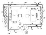
- the refrigerant, after exiting the condenser 30is conveyed to the evaporator 33 through the fluid conductor 35 .
- the refrigerantpasses through the thermal expansion valve 39 .
- the valve 39constricts the cross-sectional area of the fluid conductor 35 , thereby establishing a pressure differential between the condenser 32 and the evaporator 33 .
- the refrigerantwill be converted from a liquid on the condenser side of the valve 39 to a cold vaporized gas on the evaporator side of the valve 39 .
Landscapes
- Engineering & Computer Science (AREA)
- Physics & Mathematics (AREA)
- Mechanical Engineering (AREA)
- Thermal Sciences (AREA)
- General Engineering & Computer Science (AREA)
- Air-Conditioning For Vehicles (AREA)
Abstract
Description
Claims (41)
Priority Applications (1)
| Application Number | Priority Date | Filing Date | Title |
|---|---|---|---|
| US10/758,886US6978630B2 (en) | 2004-01-16 | 2004-01-16 | Dual-circuit refrigeration system |
Applications Claiming Priority (1)
| Application Number | Priority Date | Filing Date | Title |
|---|---|---|---|
| US10/758,886US6978630B2 (en) | 2004-01-16 | 2004-01-16 | Dual-circuit refrigeration system |
Publications (2)
| Publication Number | Publication Date |
|---|---|
| US20050155375A1 US20050155375A1 (en) | 2005-07-21 |
| US6978630B2true US6978630B2 (en) | 2005-12-27 |
Family
ID=34749596
Family Applications (1)
| Application Number | Title | Priority Date | Filing Date |
|---|---|---|---|
| US10/758,886Expired - LifetimeUS6978630B2 (en) | 2004-01-16 | 2004-01-16 | Dual-circuit refrigeration system |
Country Status (1)
| Country | Link |
|---|---|
| US (1) | US6978630B2 (en) |
Cited By (19)
| Publication number | Priority date | Publication date | Assignee | Title |
|---|---|---|---|---|
| US20090288438A1 (en)* | 2008-05-22 | 2009-11-26 | Viegas Herman H | Distributed refrigeration system |
| US20100050659A1 (en)* | 2008-08-27 | 2010-03-04 | Tony Quisenberry | Vehicle air comfort system and method |
| KR100946136B1 (en) | 2008-04-25 | 2010-03-10 | 엘에스엠트론 주식회사 | Dual freezer |
| US20100257886A1 (en)* | 2007-10-02 | 2010-10-14 | Yoshiyasu Suzuki | Refrigeration device |
| US20100326099A1 (en)* | 2008-10-28 | 2010-12-30 | Trak International, Llc | High-efficiency heat pumps |
| US20120234034A1 (en)* | 2009-11-25 | 2012-09-20 | Panasonic Corporation | Heat generating body box housing refrigeration device |
| US8881541B2 (en) | 2011-04-19 | 2014-11-11 | Liebert Corporation | Cooling system with tandem compressors and electronic expansion valve control |
| US9038404B2 (en) | 2011-04-19 | 2015-05-26 | Liebert Corporation | High efficiency cooling system |
| US20160025384A1 (en)* | 2014-07-28 | 2016-01-28 | Kimura Kohki Co., Ltd. | Heat pump air conditioner |
| US20160161165A1 (en)* | 2014-12-04 | 2016-06-09 | Mitsubishi Electric Corporation | Air-conditioning system |
| US9435553B2 (en) | 2009-08-27 | 2016-09-06 | Thermotek, Inc. | Method and system for maximizing thermal properties of a thermoelectric cooler and use therewith in association with hybrid cooling |
| US9845981B2 (en) | 2011-04-19 | 2017-12-19 | Liebert Corporation | Load estimator for control of vapor compression cooling system with pumped refrigerant economization |
| CN108692494A (en)* | 2017-04-05 | 2018-10-23 | 雷诺士工业公司 | The integrated row that interweaves divides the method and apparatus that the sub-load of condenser pipe optimizes refrigeration system |
| US20180306469A1 (en)* | 2017-04-20 | 2018-10-25 | Johnson Controls Technology Company | Row split coil systems for hvac systems |
| US20180328632A1 (en)* | 2015-11-18 | 2018-11-15 | Sanhua (Hangzhou) Micro Channel Heat Exchanger Co., Ltd. | Heat pump system |
| US10254028B2 (en) | 2015-06-10 | 2019-04-09 | Vertiv Corporation | Cooling system with direct expansion and pumped refrigerant economization cooling |
| US11305616B2 (en)* | 2016-07-05 | 2022-04-19 | Carrier Corporation | Dual compressor transportation refrigeration unit |
| USD1002676S1 (en) | 2019-08-30 | 2023-10-24 | Dometic Sweden Ab | Appliance |
| USD1026969S1 (en) | 2020-08-31 | 2024-05-14 | Dometic Sweden Ab | Refrigerator |
Families Citing this family (7)
| Publication number | Priority date | Publication date | Assignee | Title |
|---|---|---|---|---|
| EP2171385B1 (en)* | 2007-07-24 | 2021-05-19 | Johnson Controls Technology Company | Auxiliary cooling system |
| CN102803869B (en)* | 2009-06-22 | 2015-07-08 | 开利公司 | Low-ambient operating program for cooling systems with high-efficiency condensers |
| EP2534427B1 (en)* | 2010-02-08 | 2017-10-18 | Johnson Controls Technology Company | Heat exchanger having stacked coil sections |
| CN104729029B (en)* | 2013-12-24 | 2018-05-11 | 珠海格力电器股份有限公司 | Air conditioning system and control method thereof |
| CN107131670A (en)* | 2017-06-09 | 2017-09-05 | 杨玄星 | A kind of double-compressor refrigeration system of shared condensation fan |
| CN109506381A (en)* | 2018-10-21 | 2019-03-22 | 武汉富诺尔节能环保科技有限公司 | A kind of superposition type energy-saving refrigerating system |
| WO2022155129A2 (en) | 2021-01-12 | 2022-07-21 | Rheem Manufacturing Company | Interlaced microchannel heat exchanger systems and methods thereto |
Citations (20)
| Publication number | Priority date | Publication date | Assignee | Title |
|---|---|---|---|---|
| US3984224A (en) | 1973-12-10 | 1976-10-05 | Dawkins Claude W | Air conditioning system for a motor home vehicle or the like |
| US4105064A (en)* | 1976-11-08 | 1978-08-08 | Carrier Corporation | Two stage compressor heating |
| US4201065A (en)* | 1978-12-18 | 1980-05-06 | Carrier Corporation | Variable capacity vapor compression refrigeration system |
| US4332137A (en) | 1979-10-22 | 1982-06-01 | Carrier Corporation | Heat exchange apparatus and method having two refrigeration circuits |
| US4372129A (en) | 1981-05-19 | 1983-02-08 | Moore & Hanks Co. | Fail-safe refrigeration for continuous process |
| US4470270A (en) | 1981-03-18 | 1984-09-11 | Nissan Motor Company, Limited | Air conditioner system for an automotive vehicle having main and auxiliary cooling unit |
| US4474026A (en) | 1981-01-30 | 1984-10-02 | Hitachi, Ltd. | Refrigerating apparatus |
| US4506516A (en)* | 1984-04-06 | 1985-03-26 | Carrier Corporation | Refrigeration unit compressor control |
| US4676072A (en) | 1984-10-26 | 1987-06-30 | Kabushiki Kaisha Toshiba | Bypass system for a dual refrigeration cycle air conditioner |
| US4771823A (en) | 1987-08-20 | 1988-09-20 | The United States Of America As Represented By The Administrator Of The National Aeronautics And Space Administration | Self-actuating heat switches for redundant refrigeration systems |
| US4873837A (en) | 1988-10-03 | 1989-10-17 | Chrysler Motors Corporation | Dual evaporator air conditioner |
| US5205130A (en) | 1991-07-02 | 1993-04-27 | Pannell Bobby L | Dual stage AC system for recreational vehicle |
| US5231849A (en) | 1992-09-15 | 1993-08-03 | Rosenblatt Joel H | Dual-temperature vehicular absorption refrigeration system |
| US5307645A (en) | 1991-07-02 | 1994-05-03 | Pannell Bobby L | Air conditioning system for a recreational vehicle |
| US5875637A (en)* | 1997-07-25 | 1999-03-02 | York International Corporation | Method and apparatus for applying dual centrifugal compressors to a refrigeration chiller unit |
| US5943871A (en) | 1996-09-02 | 1999-08-31 | Denso Corporation | Thermal expansion valve |
| US6035655A (en) | 1997-11-21 | 2000-03-14 | International Business Machines Corporation | Modular refrigeration system |
| US6167621B1 (en) | 1998-10-30 | 2001-01-02 | International Business Machines Corporation | Center feed parallel flow cold plate dual refrigeration systems |
| US6415620B1 (en) | 2000-10-12 | 2002-07-09 | Houshang K. Ferdows | Dual loop vehicle air conditioning system |
| US6553778B2 (en)* | 2001-01-16 | 2003-04-29 | Emerson Electric Co. | Multi-stage refrigeration system |
- 2004
- 2004-01-16USUS10/758,886patent/US6978630B2/ennot_activeExpired - Lifetime
Patent Citations (20)
| Publication number | Priority date | Publication date | Assignee | Title |
|---|---|---|---|---|
| US3984224A (en) | 1973-12-10 | 1976-10-05 | Dawkins Claude W | Air conditioning system for a motor home vehicle or the like |
| US4105064A (en)* | 1976-11-08 | 1978-08-08 | Carrier Corporation | Two stage compressor heating |
| US4201065A (en)* | 1978-12-18 | 1980-05-06 | Carrier Corporation | Variable capacity vapor compression refrigeration system |
| US4332137A (en) | 1979-10-22 | 1982-06-01 | Carrier Corporation | Heat exchange apparatus and method having two refrigeration circuits |
| US4474026A (en) | 1981-01-30 | 1984-10-02 | Hitachi, Ltd. | Refrigerating apparatus |
| US4470270A (en) | 1981-03-18 | 1984-09-11 | Nissan Motor Company, Limited | Air conditioner system for an automotive vehicle having main and auxiliary cooling unit |
| US4372129A (en) | 1981-05-19 | 1983-02-08 | Moore & Hanks Co. | Fail-safe refrigeration for continuous process |
| US4506516A (en)* | 1984-04-06 | 1985-03-26 | Carrier Corporation | Refrigeration unit compressor control |
| US4676072A (en) | 1984-10-26 | 1987-06-30 | Kabushiki Kaisha Toshiba | Bypass system for a dual refrigeration cycle air conditioner |
| US4771823A (en) | 1987-08-20 | 1988-09-20 | The United States Of America As Represented By The Administrator Of The National Aeronautics And Space Administration | Self-actuating heat switches for redundant refrigeration systems |
| US4873837A (en) | 1988-10-03 | 1989-10-17 | Chrysler Motors Corporation | Dual evaporator air conditioner |
| US5205130A (en) | 1991-07-02 | 1993-04-27 | Pannell Bobby L | Dual stage AC system for recreational vehicle |
| US5307645A (en) | 1991-07-02 | 1994-05-03 | Pannell Bobby L | Air conditioning system for a recreational vehicle |
| US5231849A (en) | 1992-09-15 | 1993-08-03 | Rosenblatt Joel H | Dual-temperature vehicular absorption refrigeration system |
| US5943871A (en) | 1996-09-02 | 1999-08-31 | Denso Corporation | Thermal expansion valve |
| US5875637A (en)* | 1997-07-25 | 1999-03-02 | York International Corporation | Method and apparatus for applying dual centrifugal compressors to a refrigeration chiller unit |
| US6035655A (en) | 1997-11-21 | 2000-03-14 | International Business Machines Corporation | Modular refrigeration system |
| US6167621B1 (en) | 1998-10-30 | 2001-01-02 | International Business Machines Corporation | Center feed parallel flow cold plate dual refrigeration systems |
| US6415620B1 (en) | 2000-10-12 | 2002-07-09 | Houshang K. Ferdows | Dual loop vehicle air conditioning system |
| US6553778B2 (en)* | 2001-01-16 | 2003-04-29 | Emerson Electric Co. | Multi-stage refrigeration system |
Cited By (37)
| Publication number | Priority date | Publication date | Assignee | Title |
|---|---|---|---|---|
| US20100257886A1 (en)* | 2007-10-02 | 2010-10-14 | Yoshiyasu Suzuki | Refrigeration device |
| KR100946136B1 (en) | 2008-04-25 | 2010-03-10 | 엘에스엠트론 주식회사 | Dual freezer |
| US8037704B2 (en) | 2008-05-22 | 2011-10-18 | Thermo King Corporation | Distributed refrigeration system |
| US20090288438A1 (en)* | 2008-05-22 | 2009-11-26 | Viegas Herman H | Distributed refrigeration system |
| US8839633B2 (en) | 2008-08-27 | 2014-09-23 | Thermotek, Inc. | Vehicle air comfort system and method |
| US8443613B2 (en) | 2008-08-27 | 2013-05-21 | Thermotek, Inc. | Vehicle air comfort system and method |
| US10359216B2 (en) | 2008-08-27 | 2019-07-23 | Thermotek, Inc. | Vehicle air comfort system and method |
| US20100050659A1 (en)* | 2008-08-27 | 2010-03-04 | Tony Quisenberry | Vehicle air comfort system and method |
| US9719703B2 (en) | 2008-08-27 | 2017-08-01 | Thermotek, Inc. | Vehicle air comfort system and method |
| US20100326099A1 (en)* | 2008-10-28 | 2010-12-30 | Trak International, Llc | High-efficiency heat pumps |
| US9435553B2 (en) | 2009-08-27 | 2016-09-06 | Thermotek, Inc. | Method and system for maximizing thermal properties of a thermoelectric cooler and use therewith in association with hybrid cooling |
| US10215454B2 (en) | 2009-08-27 | 2019-02-26 | Thermotek, Inc. | Method and system for maximizing the thermal properties of a thermoelectric cooler and use therewith in association with hybrid cooling |
| US20120234034A1 (en)* | 2009-11-25 | 2012-09-20 | Panasonic Corporation | Heat generating body box housing refrigeration device |
| US8713959B2 (en)* | 2009-11-25 | 2014-05-06 | Panasonic Corporation | Heat generating body box housing refrigeration device |
| US10760827B2 (en) | 2010-09-30 | 2020-09-01 | Thermotek, Inc. | Method and system for maximizing the thermal properties of a thermoelectric cooler and use therewith in association with hybrid cooling |
| US9980413B2 (en) | 2011-04-19 | 2018-05-22 | Liebert Corporation | High efficiency cooling system |
| US8881541B2 (en) | 2011-04-19 | 2014-11-11 | Liebert Corporation | Cooling system with tandem compressors and electronic expansion valve control |
| US9845981B2 (en) | 2011-04-19 | 2017-12-19 | Liebert Corporation | Load estimator for control of vapor compression cooling system with pumped refrigerant economization |
| US9316424B2 (en) | 2011-04-19 | 2016-04-19 | Liebert Corporation | Multi-stage cooling system with tandem compressors and optimized control of sensible cooling and dehumidification |
| US9038404B2 (en) | 2011-04-19 | 2015-05-26 | Liebert Corporation | High efficiency cooling system |
| US20160025384A1 (en)* | 2014-07-28 | 2016-01-28 | Kimura Kohki Co., Ltd. | Heat pump air conditioner |
| US10047992B2 (en)* | 2014-12-04 | 2018-08-14 | Mitsubishi Electric Corporation | Air-conditioning system using control of number of compressors based on predetermined frequency ranges |
| US20160161165A1 (en)* | 2014-12-04 | 2016-06-09 | Mitsubishi Electric Corporation | Air-conditioning system |
| US10254028B2 (en) | 2015-06-10 | 2019-04-09 | Vertiv Corporation | Cooling system with direct expansion and pumped refrigerant economization cooling |
| US10465963B2 (en) | 2015-06-10 | 2019-11-05 | Vertiv Corporation | Cooling system with direct expansion and pumped refrigerant economization cooling |
| US10914498B2 (en)* | 2015-11-18 | 2021-02-09 | Sanhua (Hangzhou) Micro Channel Heat Exchanger Co., Ltd. | Heat pump system |
| US20180328632A1 (en)* | 2015-11-18 | 2018-11-15 | Sanhua (Hangzhou) Micro Channel Heat Exchanger Co., Ltd. | Heat pump system |
| US11305616B2 (en)* | 2016-07-05 | 2022-04-19 | Carrier Corporation | Dual compressor transportation refrigeration unit |
| US10415856B2 (en)* | 2017-04-05 | 2019-09-17 | Lennox Industries Inc. | Method and apparatus for part-load optimized refrigeration system with integrated intertwined row split condenser coil |
| US10837679B2 (en) | 2017-04-05 | 2020-11-17 | Lennox Industries Inc. | Method and apparatus for part-load optimized refrigeration system with integrated intertwined row split condenser coil |
| CN108692494A (en)* | 2017-04-05 | 2018-10-23 | 雷诺士工业公司 | The integrated row that interweaves divides the method and apparatus that the sub-load of condenser pipe optimizes refrigeration system |
| US20180306469A1 (en)* | 2017-04-20 | 2018-10-25 | Johnson Controls Technology Company | Row split coil systems for hvac systems |
| US11592214B2 (en)* | 2017-04-20 | 2023-02-28 | Johnson Controls Tyco IP Holdings LLP | Row split coil systems for HVAC systems |
| US11892219B2 (en) | 2017-04-20 | 2024-02-06 | Johnson Controls Tyco IP Holdings LLP | Row split coil systems for HVAC systems |
| USD1002676S1 (en) | 2019-08-30 | 2023-10-24 | Dometic Sweden Ab | Appliance |
| USD1026969S1 (en) | 2020-08-31 | 2024-05-14 | Dometic Sweden Ab | Refrigerator |
| USD1053913S1 (en) | 2020-08-31 | 2024-12-10 | Dometic Sweden Ab | Refrigerator |
Also Published As
| Publication number | Publication date |
|---|---|
| US20050155375A1 (en) | 2005-07-21 |
Similar Documents
| Publication | Publication Date | Title |
|---|---|---|
| US6978630B2 (en) | Dual-circuit refrigeration system | |
| US11179998B2 (en) | Method of heating and cooling at least one zone of a passenger compartment of a vehicle | |
| CN111791671B (en) | Vehicle temperature control device | |
| KR102065968B1 (en) | Device for distributing the coolant in an air-conditioning system of a motor vehicle | |
| US9156333B2 (en) | System for the heating, ventilation, and/or air conditioning of a vehicle, comprising at least one heat exchanger through which a heat-transfer fluid flows | |
| US4281522A (en) | Makeup air preconditioner for use with an air conditioning unit | |
| US11002471B2 (en) | Refrigeration installation, refrigeration installation system and method with refrigerant displacement | |
| US4516406A (en) | Cooling system for motor vehicles | |
| US10207566B2 (en) | Air conditioning system for vehicle including two condensers and a control door within a duct to selectively control airflow through said two condensers | |
| CN103857545B (en) | The method in refrigerant loop and this loop of control | |
| US5628203A (en) | Combined cooling and heating process and device for conditioning a room | |
| CN111380256A (en) | Heat pump system | |
| CN113942370A (en) | Automobile air conditioning system and working method thereof | |
| US4347708A (en) | Makeup air preconditioner for use with an air conditioning unit | |
| CN216153655U (en) | Vehicle-mounted thermostat system and vehicle | |
| CN101889181B (en) | Air routing design for simultaneous heating and cooling | |
| US11110777B2 (en) | Vehicle HVAC system with auxiliary coolant loop for heating and cooling vehicle interior | |
| CN111231599B (en) | Air conditioning system and method and vehicle | |
| US20200033030A1 (en) | HVAC Systems and Methods with Multiple-Path Expansion Device Subsystems | |
| US3803864A (en) | Air conditioning control system | |
| CN109130793B (en) | Air conditioning dehumidification system and automobile | |
| EP1260776B1 (en) | A heat exchanger for an air conditioning system | |
| KR102723808B1 (en) | Heat pump system for vehicle | |
| CN212604367U (en) | Automobile air-conditioning box for heat pump | |
| US12320561B2 (en) | HVAC unit with expansion device |
Legal Events
| Date | Code | Title | Description |
|---|---|---|---|
| AS | Assignment | Owner name:DOMETIC CORPORATION, INDIANA Free format text:ASSIGNMENT OF ASSIGNORS INTEREST;ASSIGNORS:WENSINK, THEODORE C.;RADLE, DAVID T.;REEL/FRAME:014900/0868 Effective date:20040108 | |
| FEPP | Fee payment procedure | Free format text:PAYOR NUMBER ASSIGNED (ORIGINAL EVENT CODE: ASPN); ENTITY STATUS OF PATENT OWNER: LARGE ENTITY | |
| STCF | Information on status: patent grant | Free format text:PATENTED CASE | |
| AS | Assignment | Owner name:DOMETIC, LLC, INDIANA Free format text:CERTIFICATE OF CONVERSION;ASSIGNOR:DOMETIC CORPORATION;REEL/FRAME:022117/0332 Effective date:20071221 Owner name:DOMETIC, LLC,INDIANA Free format text:CERTIFICATE OF CONVERSION;ASSIGNOR:DOMETIC CORPORATION;REEL/FRAME:022117/0332 Effective date:20071221 | |
| FPAY | Fee payment | Year of fee payment:4 | |
| AS | Assignment | Owner name:NORDEA BANK AB (PUBL), SWEDEN Free format text:SECURITY INTEREST;ASSIGNORS:DOMETIC CORPORATION;DOMETIC, LLC;REEL/FRAME:026683/0590 Effective date:20110506 | |
| FPAY | Fee payment | Year of fee payment:8 | |
| AS | Assignment | Owner name:DOMETIC, LLC, INDIANA Free format text:RELEASE OF SECURITY AGREEMENT SUPPLEMENT;ASSIGNOR:NORDEA BANK AB (PUBL);REEL/FRAME:037244/0267 Effective date:20151201 Owner name:DOMETIC CORPORATION, INDIANA Free format text:RELEASE OF SECURITY AGREEMENT SUPPLEMENT;ASSIGNOR:NORDEA BANK AB (PUBL);REEL/FRAME:037244/0267 Effective date:20151201 | |
| FPAY | Fee payment | Year of fee payment:12 |