US6978149B1 - Transceiver control with sleep mode operation - Google Patents
Transceiver control with sleep mode operationDownload PDFInfo
- Publication number
- US6978149B1 US6978149B1US09/728,564US72856400AUS6978149B1US 6978149 B1US6978149 B1US 6978149B1US 72856400 AUS72856400 AUS 72856400AUS 6978149 B1US6978149 B1US 6978149B1
- Authority
- US
- United States
- Prior art keywords
- receiver
- receiver portion
- active mode
- received
- transmitter
- Prior art date
- Legal status (The legal status is an assumption and is not a legal conclusion. Google has not performed a legal analysis and makes no representation as to the accuracy of the status listed.)
- Expired - Fee Related, expires
Links
- 230000004044responseEffects0.000claimsabstractdescription49
- 238000000034methodMethods0.000claimsabstractdescription27
- 238000004891communicationMethods0.000claimsdescription19
- 230000010267cellular communicationEffects0.000claimsdescription4
- 230000008569processEffects0.000abstractdescription13
- 238000012545processingMethods0.000description15
- 230000005540biological transmissionEffects0.000description7
- 238000013461designMethods0.000description7
- 238000010586diagramMethods0.000description6
- 230000006641stabilisationEffects0.000description5
- 238000011105stabilizationMethods0.000description5
- 230000008859changeEffects0.000description4
- 238000007796conventional methodMethods0.000description4
- 238000010897surface acoustic wave methodMethods0.000description4
- 230000008901benefitEffects0.000description3
- 230000001276controlling effectEffects0.000description3
- 230000000875corresponding effectEffects0.000description3
- 238000012986modificationMethods0.000description3
- 230000004048modificationEffects0.000description3
- 238000013459approachMethods0.000description2
- 125000004122cyclic groupChemical group0.000description2
- 230000001934delayEffects0.000description2
- 238000011156evaluationMethods0.000description2
- 238000001914filtrationMethods0.000description2
- 230000000977initiatory effectEffects0.000description2
- 230000003287optical effectEffects0.000description2
- 230000009467reductionEffects0.000description2
- 230000009118appropriate responseEffects0.000description1
- 230000001413cellular effectEffects0.000description1
- 230000002596correlated effectEffects0.000description1
- 238000001514detection methodMethods0.000description1
- 230000003595spectral effectEffects0.000description1
- 238000001228spectrumMethods0.000description1
- 238000012360testing methodMethods0.000description1
- 230000007704transitionEffects0.000description1
- 239000002699waste materialSubstances0.000description1
Images


Classifications
- H—ELECTRICITY
- H04—ELECTRIC COMMUNICATION TECHNIQUE
- H04W—WIRELESS COMMUNICATION NETWORKS
- H04W52/00—Power management, e.g. Transmission Power Control [TPC] or power classes
- H04W52/02—Power saving arrangements
- H04W52/0209—Power saving arrangements in terminal devices
- H04W52/0225—Power saving arrangements in terminal devices using monitoring of external events, e.g. the presence of a signal
- H04W52/0245—Power saving arrangements in terminal devices using monitoring of external events, e.g. the presence of a signal according to signal strength
- H—ELECTRICITY
- H04—ELECTRIC COMMUNICATION TECHNIQUE
- H04B—TRANSMISSION
- H04B1/00—Details of transmission systems, not covered by a single one of groups H04B3/00 - H04B13/00; Details of transmission systems not characterised by the medium used for transmission
- H04B1/06—Receivers
- H04B1/16—Circuits
- H04B1/1607—Supply circuits
- H04B1/1615—Switching on; Switching off, e.g. remotely
- H—ELECTRICITY
- H04—ELECTRIC COMMUNICATION TECHNIQUE
- H04W—WIRELESS COMMUNICATION NETWORKS
- H04W52/00—Power management, e.g. Transmission Power Control [TPC] or power classes
- H04W52/02—Power saving arrangements
- H04W52/0209—Power saving arrangements in terminal devices
- H04W52/0261—Power saving arrangements in terminal devices managing power supply demand, e.g. depending on battery level
- H04W52/0274—Power saving arrangements in terminal devices managing power supply demand, e.g. depending on battery level by switching on or off the equipment or parts thereof
- H04W52/028—Power saving arrangements in terminal devices managing power supply demand, e.g. depending on battery level by switching on or off the equipment or parts thereof switching on or off only a part of the equipment circuit blocks
- H—ELECTRICITY
- H04—ELECTRIC COMMUNICATION TECHNIQUE
- H04W—WIRELESS COMMUNICATION NETWORKS
- H04W52/00—Power management, e.g. Transmission Power Control [TPC] or power classes
- H04W52/04—Transmission power control [TPC]
- Y—GENERAL TAGGING OF NEW TECHNOLOGICAL DEVELOPMENTS; GENERAL TAGGING OF CROSS-SECTIONAL TECHNOLOGIES SPANNING OVER SEVERAL SECTIONS OF THE IPC; TECHNICAL SUBJECTS COVERED BY FORMER USPC CROSS-REFERENCE ART COLLECTIONS [XRACs] AND DIGESTS
- Y02—TECHNOLOGIES OR APPLICATIONS FOR MITIGATION OR ADAPTATION AGAINST CLIMATE CHANGE
- Y02D—CLIMATE CHANGE MITIGATION TECHNOLOGIES IN INFORMATION AND COMMUNICATION TECHNOLOGIES [ICT], I.E. INFORMATION AND COMMUNICATION TECHNOLOGIES AIMING AT THE REDUCTION OF THEIR OWN ENERGY USE
- Y02D30/00—Reducing energy consumption in communication networks
- Y02D30/70—Reducing energy consumption in communication networks in wireless communication networks
Definitions
- the present inventionrelates generally to wireless communication devices, and more particularly to transceivers having a receiver and/or transmitter which switches between a high power consumption mode and a low power consumption (or “sleep”) mode.
- the mobile transceiversmay take one of several different forms. For instance, in retail stores hand-held scanning units may be used to allow for scanning inventory bar codes. In a warehouse, portable units mounted to a vehicle may be used to gather information from the warehouse floor. In a medical environment, the mobile terminal may take the form of a pen based workslate which allows medical personnel to work with full page screens at once.
- each mobile terminalcommunicates with a networked system via a radio or optical link in order to allow for a real time exchange of information.
- the mobile terminalscommunicate through one of several base stations interconnected to the network.
- the base stationsallow for a wireless data communication path to be formed.
- Each mobile terminal and base stationcommunicate via their respective transmitter and receiver (i e., transceiver) systems.
- the transmitter and receiver in each deviceshare the same antenna and a control signal is used to switch the antenna between a transmitting and receiving mode.
- a control signalis used to switch the antenna between a transmitting and receiving mode.
- Packets of informationare a defined set of data bits which carry information such as source address, destination address, synchronization bits, data, error correcting codes, etc.
- a typical media access protocolmay provide that if a device receives a packet which requires a response, transmission of the response must be initiated within a time period on the order of 15 micro-seconds after receiving the entire original packet. This time span, or slot time, is referred to as the short inter-frame space (SIFS).
- SIFSshort inter-frame space
- the purpose of the SIFSis twofold. First, it speeds up data exchange between devices by limiting the amount of time a device can take to respond. Secondly, it limits the amount of time a device receiving the response must remain in the receiving mode. As mentioned above, since the transmitter and receiver oftentimes are connected to the same antenna, a device may miss information if it is transmitting information at the same time it could be receiving information.
- the transmitter and perhaps other non-essential circuitryis generally placed into a sleep-like state, referred to herein as a “sleep mode”, during periods where the system is receiving information.
- the sleep modethe power provided to the transmitter and other non-essential circuitry is reduced to minimum levels. Since most mobile terminals operate on battery power, the sleep mode helps maintain a longer usable battery life without the need for recharging or replacing the battery.
- a transceiver in a mobile terminalpowers up its receiver only at predetermined times or intervals during which the device may receive information. For the remainder of the time, the receiver circuitry remains in a powered down state, i.e., a sleep mode.
- the mobile terminallistens for “beacons” sent from base stations indicating there is information which needs to be transmitted to the mobile terminal.
- the mobile terminalIf information within a beacon indicates that a base station has information stored therein to be transmitted to the mobile terminal, the mobile terminal in turn transmits a “poll” packet requesting that the information be sent.
- the mobile terminalcan keep its receiver in a sleep mode at all times except when it is active to listen for a beacon and for a short time after the mobile terminal sends a poll packet and is therefore poised to receive information buffered in the base station. Thus, power may be conserved.
- the base stationmust buffer all information until such time when the mobile terminal indicates to the base station that its receiver is activated from the sleep mode to receive information.
- the undesirable result of this power saving protocolis that, in exchange for the power conservation obtained via this mode, a substantial reduction in the data exchange rate results. More specifically, since the mobile terminal receiver cannot receive information at all times there is a delay in the exchange of data.
- the mobile terminal and base stationare configured in a master-slave relationship.
- the mobile terminalis designated master and powers up its receiver from a sleep mode only during such times as the mobile terminal expects/desires to receive information. Again, however, the mobile terminal cannot receive information at all times. As a result, the data exchange rate is much lower than in the case where the mobile terminal is able to receive information at virtually any time.
- the present inventionrelates to a transceiver in which the transmitter and/or receiver is switched between an active mode and a sleep mode in order to conserve power without substantially sacrificing data exchange rates.
- the present inventionutilizes an existing receive-signal-strength-indicator (RSSI) signal and/or one or more properties of an incoming signal to control power provided to portions of the circuitry in the receiver to switch the receiver between an active mode and a sleep mode.
- the RSSI signalrepresents the signal strength of any signal which is received by the front end of the transceiver. If the strength of the RSSI signal falls below a given threshold level, power provided to non-essential portions of the circuitry within the receiver is reduced to place the receiver in a sleep mode.
- the receiverWhile in a sleep mode, the receiver continues to monitor the RSSI signal. If the RSSI signal goes above the threshold level, thus indicating an incoming signal, power is again applied to portions of circuitry within the receiver to switch the receiver back to an active mode. Since the portion of the receiver circuitry which is powered down during the sleep mode is digital circuitry which may be stabilized almost instantaneously, the receiver quickly switches from the sleep mode to the active mode. Consequently, receipt and processing of the received signal may be initiated essentially immediately.
- Such control of the power applied to the receiver circuitry based on the RSSI signal or other properties of the incoming signalprovides two distinct benefits.
- conservation of poweris achieved by requiring that the receiver circuitry be fully powered only when a signal of sufficient strength and/or intelligibility is received.
- system performanceis optimized with respect to data exchange rates as a result of the mobile terminal receiver always being able to change quickly from a sleep mode to an active mode to receive information. Consequently, no delays in the exchange of information exist as compared to mobile terminals operating in a conventional power savings mode.
- the present inventionrelates specifically to a transceiver which begins to power up the transmitter as soon as it is determined that a packet being received requires a response.
- a control circuit within the transceiverprocesses the packet as it is received to determine whether the packet requires a response. If it is determined that a response is necessary, the control circuit provides a control signal to the transmitter to power up the transmitter from a sleep mode even before the entire packet has been received. The control circuit then continues to process the remainder of the packet as it is received while the transmitter powers up from the sleep mode. In this manner, the transmitter will become stabilized much earlier. Accordingly, the transceiver is able to respond more quickly than conventional devices and is thus able to increase response times and overall data exchange rates. Moreover, battery power of the transceiver is utilized more efficiently as compared to devices which must continuously maintain the transmitter in a fully powered mode.
- a transceiver apparatusincluding: a transmitter portion for transmitting information; a receiver portion for receiving information, the receiver portion being switchable between a low power consumption mode and an active mode; and a control circuit coupled to the receiver portion for selectively switching the receiver portion from the low power consumption mode to the active mode upon detecting an information signal to be received by the receiver, whereby the receiver portion receives the information signal in the active mode.
- a transceiver apparatusincluding: a transmitter portion for transmitting information; and a receiver portion for receiving information, wherein the receiver portion includes circuitry for detecting a signal strength of a received signal, and circuitry for disabling receiver circuitry included in the receiver portion if the signal strength of the received signal is below a pre-determined threshold.
- a method for controlling a transceiver apparatushaving a transmitter portion for transmitting information; and a receiver portion for receiving information, the receiver portion being switchable between a low power consumption mode and an active mode, the method including the step of: selectively switching the receiver portion from the low power consumption mode to the active mode upon detecting an information signal to be received by the receiver, whereby the receiver portion receives the information signal in the active mode.
- a method for controlling a transceiver apparatushaving transmitter portion for transmitting information; and a receiver portion for receiving information, the receiver portion being switchable between a low power consumption mode and an active mode, the method including the step of: selectively switching the receiver portion from the active mode to the low power consumption mode if a signal strength of a received signal falls below a predetermined threshold.
- a transceiver apparatusincluding: a transmitter portion for transmitting information, the transmitter portion being switchable, based on a control input, between a low power consumption mode and an active mode during which information is transmitted; a receiver portion for receiving information, the receiver portion being switchable between a low power consumption mode and an active mode; and a control circuit coupled to the receiver portion for selectively switching the receiver portion from the low power consumption mode to the active mode by detecting an information signal to be received by the receiver, whereby the receiver portion receives the information signal in the active mode.
- a receiver apparatusincluding: a receiver portion for receiving information, wherein the receiver portion includes circuitry for detecting a signal strength of a received signal, and circuitry for disabling receiver circuitry included in the receiver portion if the signal strength of the received signal is below a predetermined threshold.
- a cellular communication systemincluding: a network; a host computer coupled to the network; a plurality of base stations coupled to the network and communicating with the host computer, each of the base stations including a base station transmitter for transmitting wireless communications and a base station receiver for receiving wireless communications; and a plurality of mobile terminals each for communicating with the network by way of at least one of the plurality of base stations, each of the plurality of mobile terminals having a mobile terminal receiver for receiving wireless communications from at least one of the plurality of base stations; wherein the receiver of at least one of the mobile terminals or base stations includes: a receiver portion for receiving information, the receiver portion being switchable between a low power consumption mode and an active mode; and a control circuit coupled to the receiver portion for selectively switching the receiver portion from the low power consumption mode to the active mode by detecting an information signal to be received by the receiver, whereby the receiver portion receives the information signal in the active mode.
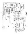
- FIG. 1is a block diagram of a transceiver having a transmitter and receiver which individually are switchable between a low power consumption mode (i.e., a “sleep mode”) and an active mode in accordance with the present invention
- a low power consumption modei.e., a “sleep mode”
- an active modein accordance with the present invention
- FIG. 2is a schematic representation of a packet format in accordance with the present invention.
- FIG. 3is a block diagram of the transceiver of FIG. 1 showing in detail the receiver in accordance with the present invention
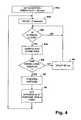
- FIG. 4is a flowchart indicating how a transceiver control circuit sets a RSSI threshold level in accordance with the present invention.
- FIG. 5is a flowchart representing how a transceiver control circuit evaluates the RSSI signal, carrier sense signal and/or length field of an incoming signal and, based on such evaluation, switches the receiver between a sleep mode and an active mode in accordance with the present invention
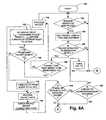
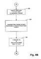
- FIGS. 6A and 6Bform a flowchart representing the operation of a transceiver control circuit for switching the transmitter between a sleep mode and an active mode in accordance with the present invention
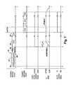
- FIG. 7is a timing diagram illustrating operation of the transceiver when switching the transmitter between a sleep mode and an active mode in accordance with the embodiment of FIGS. 6A and 6B ;
- FIGS. 8A and 8Bform a flowchart representing the operation of a transceiver control circuit for switching the transmitter between a sleep mode and an active mode in accordance with another embodiment of the present invention
- FIG. 9is a partial timing diagram illustrating operation of the transceiver in accordance with the embodiment of FIGS. 8A and 8B ;
- FIG. 10is a system diagram of a cellular communication system utilizing a plurality of transceivers in accordance with the present invention.
- a transceiver in accordance with the present inventionis generally designated 10 .
- the transceiver 10includes a radio transmitter 12 for transmitting radio signals via an antenna 14 .
- the transceiver 10includes a radio receiver 16 for receiving radio signals via the antenna 14 .
- An antenna switch 20allows the transceiver 10 to transmit or receive signals depending on the position of the switch. When the switch 20 is in the transmit (TX) position, the antenna 14 is coupled to the output of the transmitter 12 via line 22 so that the transmitter 12 can transmit information. Alternatively, when the switch 20 is in the receive (RCV) position the antenna 14 is coupled to the input of the receiver 16 by way of line 24 . The receiver 16 thereby receives information via the antenna 14 .
- the transmitter 12 and receiver 16are generally of conventional design with the exception of any specific modifications described herein.
- the transmitter 12 and receiver 16are designed to transmit and receive, respectively, digital information modulated onto a radio frequency (rf) carrier.
- rfradio frequency
- the digital informationis transmitted and received in the form of packets.
- the transmitter 12is of the type which can be selectively switched between a low power consumption mode (i.e., a sleep mode) and an active mode as discussed above. More specifically, when the transmitter 12 is in the sleep mode, the supply of power to the power amplifier (not shown), modulation circuitry (not shown), and/or various other power consuming components within the transmitter 12 is cut off or otherwise reduced.
- the transmitter 12is selectively switched between the sleep mode and active mode based on a control signal provided to a sleep/active input 28 .
- the operation of the transceiver 10 in relation to switching the transmitter 12 between a sleep mode and an active modeis described in more detail below in relation to FIG. 6A thru FIG. 9 .
- the receiver 16is also of a type which can be switched between a sleep mode and an active mode. While the receiver 16 is in a sleep mode, the power supplied to non-essential circuitry within the receiver 16 (i.e., circuitry not necessary for operation during the sleep mode) is cut off or otherwise reduced. Hence, the load on the battery 26 to power the transceiver 10 again is reduced.
- the receiver 16 of the present inventioncan receive information at any time. Specifically, the receiver 16 is capable of switching from a sleep mode to an active mode substantially instantaneously as a signal is received.
- the receiver 16is able to remain in a sleep mode until such time as an incoming signal is detected. Details regarding the operation of the transceiver 10 in relation to switching the receiver 16 between a sleep mode and active mode are provided below with reference to FIGS. 3-5 .
- the transceiver 10further includes a control circuit 30 which processes the information which is communicated via the transceiver 10 .
- the control circuit 30is made up of a medium access controller (MAC) which is connected to the transmitter 12 and receiver 16 by way of lines 32 and 34 , respectively.
- the MAC 30provides a RCV/TX control signal on line 36 to the antenna switch 20 in order to selectively switch the antenna switch 20 between the transmit and receive positions. Additional control signals are provided by the MAC 30 in order to control the active/sleep states of the transmitter 12 and receiver 16 .
- the MAC 30provides a sleep/active control signal on line 38 to the input 28 in order to selectively switch the transmitter 12 between the sleep and active modes as is discussed more fully below.
- the MAC 30receives a receive signal strength indicator (RSSI) signal on line 39 . Based on the RSSI signal, the MAC 30 provides control information to the receiver 16 via line 34 . Such control information is processed by the receiver 16 in order to control whether the receiver 16 is in an active mode or a sleep mode.
- RSSIreceive signal strength indicator
- the MAC 30preferably includes a series of state machines (not shown) which process incoming data packets received by the receiver 16 . As part of the processing, the MAC 30 strips off individual fields of the incoming packet as described below in order to forward selective information to the receiver 16 and to determine which packets require a response. In the event a packet requires a response, the MAC 30 provides a control signal on line 38 to switch the transmitter 12 from a sleep mode to an active mode. In addition, the MAC provides a control signal on line 36 to switch the antenna switch 20 from the receive position to the transmit position. Thereafter, the transmitter 12 can transmit an appropriate response.
- state machinesnot shown
- the MAC 30When the transmitter 12 is not being used, the MAC 30 provides a control signal on line 38 to switch the transmitter 12 back to the sleep mode in order to allow the transceiver 10 to conserve battery power. In addition, the MAC 30 switches the antenna switch 20 back to the receive position. Furthermore, while in receive mode, the MAC 30 provides signals to control circuitry within the receiver 16 which allows the receiver 16 to be placed in a sleep mode during times when no information is being transmitted to the transceiver 10 for its receipt.
- the MAC 30differs from conventional medium access controllers in several ways. For instance, the MAC 30 does not wait until the entire packet has been received by the receiver 16 before providing a control signal on line 38 to switch the transmitter 12 from a sleep mode to an active mode. Rather, as a packet of information is received by the transceiver 10 via the receiver 16 , the MAC 30 processes the packet in order to determine if a response is necessary. The MAC 30 receives the packet from the receiver 16 via line 34 as the packet is received. As is explained more fully below, the MAC 30 evaluates the contents of a type/address field ( FIG. 2 ) included in the packet, such field containing information regarding the type of packet which has been received.
- a type/address fieldFIG. 2
- the MAC 30evaluates the field for the presence of some type of indicia as to whether the packet is of the type that requires a response or is of the type which does not require a response. In the event the MAC 30 determines that an incoming packet does require a response, the MAC 30 can immediately provide the sleep/active control signal on line 38 so as to initiate the powering up of the transmitter 12 from the sleep mode to the active mode.
- the transmitter 12can be transitioning from the sleep mode to a stable active mode.
- the transmitter 12can therefore be in a stable state either by the time the entire packet has been received and processed or shortly thereafter.
- all or the majority of the SIFS slot timeis available for responding to the packet as will be more fully appreciated based on the description presented below. Consequently, a high transceiver data exchange rate may be maintained with minimal concern for transmitter circuitry stabilization time.
- an optimal data exchange ratecan still be achieved.
- the MAC 30includes a microprocessor (not shown in FIG. 1 ) which maintains a dynamically changing RSSI threshold signal representing the current noise floor.
- the thresholdis utilized by receiver control circuitry to compare with the RSSI signal and to determine when to switch the receiver 16 from a sleep mode to an active mode.
- the RSSI signalis provided to the MAC 30 from the front end of the receiver 16 which remains active even during a sleep mode.
- the RSSI signalexceeds a threshold signal calculated by the MAC 30 , it is determined that an incoming signal is available to be received by the receiver 16 .
- the portion of the receiver 16 which is powered down during the sleep modeis then awoken in order that the information may be received.
- the portion of the receiver 16 which is powered down during the sleep modeis primarily digital circuitry which can be fully activated and stabilized relatively instantaneously compared to the timing of the incoming signal. This allows the incoming signal or packet to be received fully without any significant loss of information. After the incoming signal is received, the receiver 16 is again placed in a sleep mode until another signal is received.
- the receiver 16being able to remain in a sleep mode until such time as an incoming signal is received.
- a high data exchange rateis maintained since the receiver 16 is not limited to receiving information only at predetermined times as in conventional systems.
- FIG. 2shows the format of an exemplary data packet 45 received by the transceiver 10 of FIG. 1 .
- the data packet 45is represented by a sequence of data and/or control information which is segmented into respective fields.
- the data packet 45 together with the information contained thereinis constructed by the device which subsequently transmits the packet 45 to the transceiver 10 .
- the format of the data packet 45will typically be governed by the system protocol as is conventional.
- the data packet 45includes, in order, a synchronization field 46 including synchronizing bits for synchronizing the receiver 16 ; a header field 47 including header information such as the source address of the data packet, the header field 47 including at the end thereof a length field 48 including information regarding the length of the packet (e.g., number of bits); a type/address field 49 ; a data field 50 ; and a cyclic redundancy check (CRC) field 51 .
- CRCcyclic redundancy check
- the type/address field 49includes the destination address of the packet 45 and information indicating whether or not the packet is of a type which requires a response.
- the type/address field 49can include one or more bits which are set to indicate that the transceiver 10 is required to transmit a positive and/or negative acknowledgment of receipt of the packet 45 .
- the type/address field 49can include information which identifies the packet as a type which needs to be processed and transmitted by the transceiver 10 in order to forward the information to another location.
- the type/address field 49has one or more predetermined indicia therein for indicating whether the packet 45 is of a type which requires that the transceiver 10 respond by transmitting information or is of a type which does not require that the transceiver 10 respond by transmitting information.
- the type/address field 49is shown located approximately in the middle of the data packet 45 , although it will be appreciated that the type/address field 49 could be located elsewhere in the packet. In the preferred embodiment, however, the type/address field 49 is located within the initial half of the data packet 45 and most preferably towards the front of the packet 45 .
- the data packet 45includes a data field 50 which contains the primary data being sent within the packet.
- the data field 50is then followed by a cyclic redundancy check (CRC) field 51 which includes a CRC code for error detection as is conventional.
- CRCcyclic redundancy check
- the receiver 16is shown in detail within the transceiver 10 .
- the receiver 16includes a front end 52 which is primarily an analog circuit for downconverting and demodulating signals received by the antenna 14 , and a primarily digital back end 53 for digitizing, filtering and decoding received signals.
- the receiver 16includes an active/sleep mode control circuit 54 which selectively switches the receiver 16 between the sleep mode and active mode based on information provided by the MAC 30 . More particularly, the control circuit 54 is designed to disable/power down the filtering and decoding circuitry in the back end 53 during the sleep mode as described in more detail below.
- the antenna 14is connected to the antenna switch 20 which controls whether the antenna 14 functions to transmit or receive data at any instant in time.
- the antenna switch 20can be any type switch for switching the antenna 14 between a transmitting mode and a receiving mode for example, a PIN-diode based single pole-double throw (SPDT) type switch as is known.
- the control line 36couples the antenna switch 20 to the MAC controller 30 which in turn controls the mode in which the antenna 14 performs.
- the antenna switch 20is normally in the receive position except when the transceiver 10 is transmitting information.
- signals received by the antenna 14are input to a low noise amplifier (LNA) 58 included at the input to the receiver 16 .
- the LNA 58amplifies incoming signals which later will be demodulated to extract data.
- the amplified signal from the LNA 58is provided to a mixer 60 which mixes the incoming signal down to an intermediate frequency which can be readily processed by the receiver 16 as is well known in the art.
- the mixer 60mixes the incoming signal down to an intermediate frequency in the range of 200 to 500 MHZ, for example.
- the output of the mixer 60is input to a surface acoustic wave (SAW) filter 62 which filters the incoming signal and reduces noise as is conventional.
- SAWsurface acoustic wave
- the filtered signal from the SAW filter 62is input to a low noise amplifier (LNA) 63 .
- the LNA 63further amplifies the incoming signal for subsequent processing.
- the LNA 63provides as an output a received signal strength indicator (RSSI) signal on line 39 .
- the RSSI signalis provided using conventional techniques which are well known in the art. As is known, the RSSI signal is an analog signal which is indicative of the power level of the received signal.
- the RSSI signal on line 39is input to the MAC 30 for further processing such that, as discussed below in connection with FIG. 4 , the MAC 30 computes an RSSI threshold level.
- the RSSI signal on line 39is also input to an A/D converter 75 which converts the analog RSSI signal into a multi-bit digital representation.
- the digitized RSSI signalserves as one of the inputs to a digital comparator 77 .
- the other input to the digital comparator 77is provided by the output of a threshold register 80 .
- the threshold register 80functions to hold the RSSI threshold value which is provided to the threshold register 80 from the MAC 30 .
- the digital comparator 77compares the current RSSI signal as obtained from line 39 with the threshold value provided from the threshold register 80 . In the event the RSSI signal exceeds the threshold value, such event being indicative that an incoming signal is being received, the digital comparator 77 provides a control output on line 81 indicating the same.
- the digital comparator 77provides a control output on line 81 indicating that the RSSI signal is less than the threshold value and that no incoming signal or packet is being received.
- the control output on line 81is provided to a timing control circuit 82 which is responsible for providing appropriate timing signals to the digital circuitry in the receiver back end 53 in order to ensure that the digital receiver circuitry is enabled and disabled at the proper times.
- the timing control circuit 82is preferably made up of one or more state machines which are configured to provide a control signal on line 83 which is switchable between an active mode level and a sleep mode level.
- the control signal on line 83is input to a decimator 84 and a digital decoding logic circuit 85 .
- the decimator 84 and the decoding logic 85are conventional in that they are used to filter the incoming signal and to decode the data, respectively.
- the decimator 84includes correlator circuitry (not shown) which filters the I and Q components of the incoming signal.
- the decoding logic 85extrapolates the data received in the incoming signal.
- the decimator 84 and the decoding logic 85each receive respective clock signals originating from a system clock 86 which is divided down to the appropriate frequency by a clock dividing circuit 88 .
- the decimator 84 and decoding logic 85are configured such that all of the respective circuitry therein receives full operating voltages (e.g., V cc , etc.) and is thus fully enabled for operation.
- the decimator 84 and the decoding logic 85is designed such that all or part of the operating voltages provided to the respective circuitry therein is reduced or completely cut off so as to disable the circuits.
- the power draw of the receiver 16 due to the decimator 84 and the decoding logic 85is substantially reduced during the sleep mode.
- the system clock 86 and clock dividing circuit 88continue to operate even in the sleep mode.
- the receiver 16when the receiver 16 is switched from a sleep mode to an active mode there is no substantial delay in the digital circuitry waiting for the system clock or related circuitry to stabilize. Since the system clock and clock signals provided to the decimator 84 and decoding logic 85 are operating at a substantially higher rate than the bit rate of the incoming signal, the decimator 84 and decoding logic 85 will stabilize within a few system clock cycles. Accordingly, the receiver 16 is stabilized substantially instantaneously upon the control signal on line 83 being switched to the active mode level from the sleep mode level.
- the timing control circuit 82is configured to continue to evaluate the level of the RSSI signal alone or in combination with one or more other criteria of the received signal to avoid switching the receiver 16 back to the sleep mode prior to all information being received properly and processed as discussed below in relation to FIG. 5 .
- the MAC 30provides to the timing control circuit 82 via line 89 information relating to a length of each packet received.
- a carrier sense comparator 90 included in the receiver 16provides information on line 91 to the timing control circuit 82 relating to the intelligibility of the incoming signal. Such information is processed by the timing control circuit 82 in case an information signal is received intact while not necessarily having a RSSI signal strength which remains above the RSSI threshold.
- the output of the LNA 63is input to a conventional quadrature demodulator circuit 65 which includes a first mixer 66 and a second mixer 67 having a 90 degree phase shifter 68 associated therewith which is used to produce I and Q components of the incoming signal using conventional techniques.
- the I and Q componentsare filtered by respective SAW filters 71 and are input to respective A/D converters 73 .
- the digitized I and Q components from the A/D converters 73are coupled to the decimator 84 which is used to correlate the incoming I and Q signals and to extrapolate the transmitted data as is conventional. Digital correlation techniques such as that described in U.S. patent application Ser. No. 08/335,328, filed on Nov. 7, 1994 could be used. Once correlated, the I and Q signals are fed to the digital decoding logic circuit 85 which is coupled to the decimator 84 .
- the decoding logic circuit 85includes circuitry for data decoding, PN code acquisition, PN code tracking and carrier tracking, for example, as are all conventional.
- the decimator 84 and decoding logic circuit 85may hereinafter also be referred to as the digital receiver circuitry.
- the carrier sense comparator 90computes a carrier sense signal based on the square root of (I 2 +Q 2 ).
- the carrier sense signalis indicative of whether there is sufficient correlation among the received information for the signal to be interpreted.
- the carrier sense comparator 90compares the value of the carrier sense signal as computed therein against a predetermined threshold criteria based upon which it can be concluded that the information in the received signal is likely to be intelligible.
- Techniques for obtaining such a carrier sense signalare utilized, for example, in the Model T440 and T441 integrated circuits sold by Aironet of Aironet Wireless Communications, Inc., Fairlawn, Ohio.
- the preferred embodiment of the present inventionutilizes the RSSI signal to switch the receiver 16 between a sleep mode and an active mode based on when the RSSI signal is below the threshold level set by the MAC 30 .
- the threshold levelis generally set to approximately 10 dbm above the noise floor for the environment in which the mobile terminal is located. Further, as the noise floor changes, the transceiver 10 updates the threshold level. By maintaining the threshold level at 10 dbm above the noise floor it is likely that digital receiver circuitry will not be activated by noise signals and thereby waste power.
- the RSSI threshold levelchanges in relation to the noise floor in a specific frequency channel in order to best optimize system performance. More particularly, if the noise floor drops system performance may be increased by proportionally lowering the threshold level. This is because it may be possible to correlate signals received at the lower power densities thereby effectively increasing the communication range of the system. Alternatively, if the noise floor increases the RSSI threshold is increased such that the possibility of the noise level becoming sufficient to cause the receiver 16 to switch from a sleep mode to an active mode based on the noise is reduced or eliminated.
- the microprocessor 74 in step 93 ainitializes itself upon the transceiver 10 being powered up or reset, for example.
- the microprocessor 74sets the threshold level in the threshold register 80 at a default level of ⁇ 80 dbm.
- signals received at or below this power density levelwill be noise signals and therefore it is not desirable to provide power to the digital receiver circuitry (e.g., the decimator 84 and the decoding logic 85 ) since power will be consumed unnecessarily.
- the noise levelis higher than ⁇ 80 dbm.
- the microprocessor 74periodically updates the RSSI threshold level approximately every five seconds in the preferred embodiment as will be explained, although other intervals are certainly possible. Following step 93 a , the microprocessor 74 pauses for five seconds as shown in step 93 b . The microprocessor 74 then proceeds to step 93 c in which the microprocessor 74 checks whether the frequency channel the receiver 16 is operating within is clear of transmissions. Such determination may be based on the clear channel assessment signal which is conventionally available within the MAC 30 . As is known, MAC controllers typically generate a clear channel assessment signal indicative of whether the frequency channel in which signals are being received is free from any incoming signals. If no incoming signals are being received, the clear channel assessment signal indicates that the channel is clear.
- the RSSI signal at such timeis representative of the strength of the noise level as opposed to an incoming information packet. If the clear channel assessment signal does not indicate that the channel is clear, this indicates that some type of communication is occurring in the transceiver 10 and therefore the noise level cannot currently be sampled.
- step 93 cthe microprocessor 74 checks the clear channel assessment signal. If the channel is not clear as determined in step 91 , the microprocessor 74 continues to loop through step 93 c to check the status of the frequency channel. Upon the frequency channel becoming free as determined in step 93 c , the microprocessor 74 proceeds to step 93 d in which it samples and stores the RSSI signal on line 39 (in dbm) in order to determine the current noise floor. However, in order to reduce the probability of error, the microprocessor 74 is programmed to sample the frequency channel a multiple number of times (e.g., four times) within a predefined period of time prior to re-setting the threshold level.
- the microprocessor 74is programmed to sample the frequency channel a multiple number of times (e.g., four times) within a predefined period of time prior to re-setting the threshold level.
- step 93 dthe microprocessor 74 proceeds to step 93 f in which the microprocessor 74 checks to see if four samples have been taken since the last time the RSSI threshold in register 80 was updated. If not, the microprocessor 74 proceeds to step 94 in which the microprocessor 74 waits 50 milliseconds between samples and then returns to step 93 c . Otherwise, if four samples have been taken since the last update the microprocessor 74 continues to step 95 . Hence, after the microprocessor 74 obtains four samples of the RSSI signal when the frequency channel is clear the microprocessor 74 in step 95 computes the average of the four RSSI samples obtained via step 93 d . In this manner, the MAC 30 estimates the current noise floor.
- the microprocessor 74 in step 96sets or otherwise updates the RSSI threshold in register 80 to the average RSSI value calculated in step 95 plus 10 dbm.
- the microprocessor 74takes the average value calculated in dbm in step 95 , adds 10 dbm, and writes the result to the threshold register 80 ( FIG. 1 ) via line 34 .
- the reason for setting the RSSI threshold at approximately 10 dbm above the calculated noise flooris so that received noise is not inadvertently misinterpreted as an incoming signal thereby unnecessarily powering up the digital receiver circuitry and wasting power.
- some value other than 10 dbmcould be utilized depending on the circumstances.
- the microprocessor 74returns to step 93 b where it delays five seconds before again reevaluating and updating the RSSI threshold to represent the current noise floor level.
- the procedure represented in FIG. 4continues more or less throughout the operation of the transceiver 16 .
- the timing control circuit 82consists of a state machine in order to provide fast processing of information. The operation of the timing control circuit 82 will now be described in detail with reference to FIG. 5 .
- the timing control circuit 82initializes itself upon the transceiver 10 being powered up, for example.
- the timing control circuit 82determines whether the RSSI signal on line 39 is greater than the RSSI threshold value computed by the MAC 30 . Specifically, the timing control circuit 82 checks the output of the digital comparator 77 on line 81 to determine if the RSSI signal exceeds the current RSSI threshold value. If yes, the timing control circuit 82 outputs on line 83 a control signal at the active mode level which serves to immediately power up the decimator 84 and decoding logic 85 as represented in step 97 c .
- control signal on line 83may control a switch in the decimator 84 and the decoding logic 85 which connects the main supply voltage(s) to the respective components. Consequently, as soon as an incoming signal is received causing the RSSI signal to exceed the RSSI threshold value, the receiver 16 is fully powered up to receive the incoming signal.
- step 97 cthe timing control circuit 82 returns to step 97 b where it again checks whether the RSSI signal is greater than the threshold value. If yes, the control signal on line 83 continues to keep the receiver 16 in an active mode as represented in step 97 c . Hence, as long as the RSSI signal remains above the threshold value, indicating the presence of a signal, the timing control circuit 82 loops through steps 97 b and 97 c and the receiver 16 remains in an active mode.
- the preferred embodiment of the inventionfirst looks to various other criteria to determine if perhaps it is still possible to receive and comprehend the packet. Thus, assuming the receiver 16 has been switched to an active mode but the RSSI signal drops below the threshold value, in step 97 b the timing control circuit 82 proceeds to step 97 d .
- step 97 dthe timing control circuit 82 looks to the output of the carrier sense comparator 90 as provided on line 91 to determine if the carrier sense signal meets the threshold criteria as determined therein. If such comparison indicates that the packet is still intelligible, the timing control circuit 82 proceeds to step 97 e in which the receiver 16 is maintained in the active mode by the output on line 83 . The system then returns to step 97 b.
- step 97 fthe timing control circuit 82 looks to the length field information which is provided on line 89 . In the event the MAC 30 is able to obtain the length field data from the incoming packet as provide by the receiver 16 via line 97 g , such information is provided by the MAC 30 on line 89 . Otherwise, the information on line 89 as provided by the MAC 30 indicates that length field information is not available.
- the timing control circuit 82proceeds to step 97 h wherein the output provided on line 83 causes the receiver 16 to remain in an active mode for a time corresponding to the remaining length of the packet being received in terms of time.
- time durationcan be computed easily by the timing control circuit 82 based on the known length of the field, the known bit rate of the incoming signal, the time at which the length of field information was initially obtained, etc.
- the receiver 16will remain in an active mode at least long enough to receive the entire incoming packet.
- the timing control circuit 82returns to step 97 b .
- the timing control circuit 82will perform three levels (Levels 1-3) of analysis before concluding that an incoming signal no longer exists and switching the receiver 16 to the sleep mode.
- Levels 1-3the RSSI signal will typically be the best indicator of the presence of a packet to be received
- the carrier sense and length fieldare also useful indicators.
- the CRC field in each packetserves as an indication of the true integrity of the received packet as is conventional.
- step 97 bIn the event there is no incoming signal or an incoming signal has been recently completed, the timing control circuit 82 will proceed directly from step 97 b , to step 97 d , to step 97 f , and then to step 97 i .
- the RSSI signalIn the absence of an incoming signal, the RSSI signal will be below the threshold (step 97 b ), the carrier sense signal will not meet the threshold criteria (step 97 d ), and the length filed will not be ascertainable (step 97 f ). Consequently, in 97 i the receiver 16 will be placed in the sleep mode to the extent it has not already been.
- the transceiver 10is capable of maintaining the receiver 16 in a sleep mode until such time as a signal is received.
- the receiver 16is then switched to an active mode relatively instantaneously in order to receive and process the signal.
- the transceiver 10is able to maintain a high data exchange rate while still conserving power.
- FIGS. 6A and 6Boperation of the transceiver 10 with respect to reducing power consumption of the transmitter 12 will now be described.
- the MAC 30is generally responsible for switching the transmitter 12 between a sleep mode and an active mode.
- FIGS. 6A and 6Brepresent a flowchart showing the sequence of operation of the MAC 30 in relation to the transceiver 10 .
- the MAC 30 together with the remainder of the transceiver 10is initialized upon being powered up via an ON/OFF switch, for example.
- the transmitter 12 as controlled by the MAC 30is normally in a sleep mode and the antenna switch 20 is in the receive position.
- the receiver 16receives any incoming packets, and as a given packet 45 is being received, the receiver 16 provides the packet 45 in sequence to the MAC 30 .
- the MAC 30determines whether header information belonging to a new packet as found in header field 47 ( FIG. 2 ) has been received via the receiver 16 . If no, the MAC 30 remains in a loop around block 102 until such header information is received. When the MAC 30 does receive header information in block 102 so as to indicate a new packet is being received, the MAC 30 proceeds to block 104 .
- the MAC 30processes the length and type/address fields 48 and 49 , respectively (FIG. 2 ). Specifically, the MAC 30 determines the length of the packet following the header field 47 based on the information in the length field 48 , and determines the destination address and packet type based on the information in the type/address field 49 .
- the MAC 30proceeds to block 106 in which the MAC 30 determines, based on the destination address, if the packet is directed to the particular transceiver 10 in which the MAC 30 resides. For example, if the destination address in field 49 is that of the particular transceiver 10 , it is determined in block 106 that the packet is in fact directed to the particular transceiver 10 . Alternatively, the destination address may indicate that the received packet has been broadcasted and is thus directed to and intended to be received by the particular transceiver 10 . If the packet is determined to be directed to the transceiver 10 , the MAC 30 proceeds to block 108 . Otherwise, the packet is dismissed as being directed to another device and the MAC 30 returns to block 102 as shown in FIG. 6 A.
- the MAC 30 in block 108evaluates the type information from the type/address field 49 to determine if the packet being received is of the type which requires a response. For example, the MAC 30 determines if the type/address field 49 includes indicia indicating that a receipt acknowledgment is necessary or that the transceiver 10 will be required for some other reason to transmit some type of response to the packet. If in block 108 the MAC 30 determines that the packet is not of the type which needs to be responded to, the MAC 30 proceeds directly to block 110 wherein it carries out any other processing which may be required with respect to a packet that does not necessitate a response. Thereafter, the MAC 30 returns to block 102 where it waits for another header indicating receipt of a new packet.
- the MAC 30determines in block 108 that the packet being received is of the type that requires a response, however, the MAC 30 proceeds to block 112 .
- the MAC 30provides a control signal on line 38 ( FIG. 1 ) to switch the transmitter 12 from the sleep mode to an active mode.
- the MAC 30provides a control signal in block 112 to power up the circuitry in the transmitter 12 . In this manner, extra time can be gained to allow the transmitter circuitry to stabilize prior to transmission of a response.
- typical MAC protocolsonly allow a total of 15 ⁇ s for the transceiver 10 to begin responding after receiving the entire packet 45 .
- the MAC 30utilizes the information as soon as it is extrapolated from the packet to begin powering up the transmitter 12 to an active mode.
- the MAC 30receives the packet data from data field 50 ( FIG. 2 ) via the receiver 16 for conventional processing as represented in block 114 .
- the MAC 30then proceeds to block 116 in which the MAC 30 checks the error correcting code in the CRC field 51 of the incoming packet. Based on the error correcting code and using conventional techniques, the MAC 30 determines in block 118 whether an error has occurred in the receipt of the packet. If an error has occurred, the MAC 30 proceeds to block 120 in which it is determined whether a negative acknowledgment of receipt is required. Specifically, the MAC 30 refers to the information from the type/address field 49 as obtained in block 104 to determine if the received packet is of the type that requires a response indicating that the received packet included an error.
- the MAC 30If it is not necessary for the transceiver 10 to acknowledge that the packet as received included errors, the MAC 30 provides a control signal on line 38 to switch the transmitter 12 back to the sleep mode, as represented in block 121 , since there is no need to respond to the erroneous packet. Thereafter, the MAC 30 returns to block 102 to await the next packet header.
- the MAC 30proceeds to block 122 .
- the MAC 30 in block 122provides a control signal on line 36 ( FIG. 1 ) in order to change the antenna switch 20 to the transmit position upon receipt of the entire packet.
- the MAC 30sends a control signal in block 124 to the transmitter 12 via line 32 instructing to transmitter 12 to begin transmitting a response.
- the responsewill be an acknowledgment that the transceiver 10 has successfully received the packet 45 .
- the particular content of the responsewill depend on the particular application and is not intended to limit unnecessarily the scope of the invention as will be appreciated.
- the timing of the control signal provided by the MAC 30 on line 32is designed such that the transmitter 12 will begin transmitting the response only when both (i) the entire incoming packet has been received; and (ii) at least a time T sa has elapsed following the initiation of the powering up of the transmitter 12 in block 112 , where T sa represents the time period required for the transmitter circuitry to stabilize upon being switched from the sleep mode to the active mode.
- T sarepresents the time period required for the transmitter circuitry to stabilize upon being switched from the sleep mode to the active mode.
- the value of T sawill depend on the particular design of the transmitter 12 , but such value can easily be determined based on routine testing and evaluation as will be appreciated.
- the MAC 30then proceeds from block 124 to block 126 .
- block 126following completion of the response transmission the MAC 30 provides a control signal on line 38 to switch the transmitter 12 back to the sleep mode.
- the MAC 30provides a control signal on line 36 to change the antenna switch 20 back to the receive position. Thereafter, the MAC 30 returns to block 102 to await the header of the next packet. The above-described sequence is then repeated for each packet received by the transceiver 10 .
- FIG. 7is a timing diagram illustrating the operation of the MAC 30 in connection with the receipt of a packet 45 and the provision of the various control signals within the transceiver 10 as set forth in FIGS. 6A and 6B .
- the receiver 16begins receiving and the MAC 30 begins processing an incoming packet 45 (block 102 ).
- the MAC 30as mentioned above includes a state machine capable of high speed processing of the incoming packet.
- the timing at which the MAC 30 processes the respective fields of the incoming packet 45is approximately identical to the timing at which the respective fields are being received by the receiver 16 .
- the packet 45 as shown in FIG. 7can be considered as representing both the time at which the packet 45 is received by the receiver 16 and the time at which the packet is processed by the MAC 30 .
- the SIFS slot timecan be defined as a time period beginning at a time (t 3 ) when the last symbol or data value in the packet 45 being received reaches the antenna 14 ( FIG. 1 ) from the transmitting device.
- the SIFS slot timeends at a time period (t 4 ) when the first symbol or data value in a response packet transmitted by the transmitter 16 exits the antenna 14 en route to the device being responded to.
- the actual time at which the last symbol or data value in the packet 45 being received reaches the antennais defined as the time at which the entire packet 45 is received by the receiver 16 .
- the MAC 30finishes processing the information in the type/address field 49 (blocks 104 , 106 and 108 ).
- the MAC 30substantially immediately provides the sleep/active control signal on line 38 to switch the transmitter 12 from the sleep mode to the active mode (block 112 ).
- the circuitry in the transmitter 12begins to transition from the sleep mode to a stable active mode beginning at time t 2 .
- the transmitter 12continues to power up from a non-stable state towards a stable state.
- the MAC 30then provides the RCV/TX control signal on line 36 ( FIG. 1 ) to change the antenna switch 20 from the receiving position to the transmitting position (block 122 ).
- the SIFS slot timebegins for initiating a response to the packet 45 .
- the SIFS timeis equal to 15 ⁇ s, for example.
- the transmitter 12has been powering up from the sleep mode all during such time as the data field 50 was being received and processed.
- the transmitter circuitrytherefore becomes stabilized much earlier than conventional systems and preferably even before. This enables the transmitter 12 to begin transmitting a response (block 124 ) much earlier and reliably.
- the time period T sa required by the transmitter 12 to stabilize from the sleep modeis approximately equal to the SIFS time slot, there is still all or at least a substantial amount of time within the SIFS slot time to initiate the response.
- T saThe particular value of T sa will depend on the particular transmitter design, of course.
- the timing of the control signal provided on line 38 to power up the transmitter 12is such that the transmitter circuitry will be stabilized before entering the SIFS window.
- the type/address field 49may be located within the initial half of the packet 45 and preferably closer to the front of the packet so as to maximize the available time for the MAC 30 to detect whether the packet requires a response and begin powering up the transmitter 12 .
- the transmitter 12completes transmission of the response and notifies the MAC 30 of such completion via line 32 (FIG. 1 ).
- the MAC 30in turn switches the transmitter 12 back to the sleep mode via the sleep/active control signal on line 38 and switches the antenna 14 back to the receiving position (block 126 ). Thereafter, the transmitter 12 returns to the sleep mode as represented by the TX mode waveform in FIG. 7 .
- the transceiver 10 of the present inventionutilizes a portion of the time spent receiving and processing a packet 45 to power up the transmitter 12 in the event the packet requires a response.
- the present inventioncan operate at higher data exchange rates while still managing to conserve battery power. If no response is required, the transmitter 12 is not needlessly woken from the sleep mode.
- the embodiment described above with respect to FIGS. 6A and 6Bassumes that the packets 45 received by the transceiver 10 are relatively short in length. More specifically, it is assumed that the length of the packet 45 (with respect to time) following the type/address field 49 is shorter than time period T sa as shown in FIG. 7 . If not, the transmitter 12 may remain idle in the fully powered active state for a longer time than necessary waiting for processing of the incoming packet to be completed. Although the transceiver 10 will be fully operational in such case, this can result in an additional power drain on the battery 26 . As a practical matter, however, the additional power drain is relatively minimal compared to the overall power savings and circuit simplicity. Thus, the embodiment of FIGS. 6A and 6B is quite suitable.
- the present inventionalso provides active/sleep signals to both digital and analog components of the receiver 16 .
- FIGS. 8A and 8Brepresent another embodiment of the invention which takes into account the length of each packet 45 as it is received.
- FIGS. 8A and 8Bshow a flowchart representing the sequence of operation of the MAC 30 according to such embodiment. The majority of sequence blocks are identical to those discussed above in connection with FIGS. 7A and 7B . Hence, only the differences will be discussed herein to avoid redundancy.
- the MAC 30proceeds from block 108 to block 130 in the event it is determined that the packet is of the type requiring a response.
- the MAC 30determines if the length of the remainder of the packet 45 following the type/address field 49 is greater with respect to time than the time period T sa .
- the MAC 30can be designed to make such determination based on a knowledge of the packet length as obtained in block 106 , the number of bits included within the type/address field 49 , the data rate, and the known time period T sa .
- the length field 48 in the preferred embodimentincludes information relating to the number of bits in the packet 45 following the length field. Such information is obtained by the MAC 30 in block 104 as discussed above.
- the MAC 30having processed the type/address field 49 , is designed to count the number of bits in the type/address field 49 . Then, by subtracting the number of bits in the type/address field 49 from the packet length obtained in block 104 , the number of bits remaining in the remainder of the packet (e.g., the data field 50 and CRC field 51 ) is determined by the MAC 30 .
- the remaining length of the packet(T remainder ) in terms of time can be calculated.
- the MAC 30can then compare the remaining length to the time period T sa as represented in block 130 .
- the MAC 30proceeds to block 112 whereby the MAC 30 provides a control signal on line 38 to the transmitter 12 substantially immediately following receipt of the type/address field 49 in order to switch the transmitter from the sleep mode to the active mode.
- the MAC 30proceeds to block 132 .
- the MAC 30schedules a delay T del for providing the control signal on line 38 to initiate switching the transmitter from the sleep mode to the active mode.
- T delin such case is equal to the length of the remainder of the packet in terms of time minus the time period T sa .
- the MAC 30proceeds directly to block 114 .
- the MAC 30then goes to block 124 ′ in which the MAC 30 provides a control signal to the transmitter 12 via line 32 instructing the transmitter to begin transmitting at the end of the received packet, e.g., at a time T del +T sa following the end of the type/address field 49 .
- the MAC 30waits during a delay T del before providing the control signal on line 38 . This avoids the transmitter 12 remaining idle in a fully powered state for an appreciable amount of time while the remainder of the packet is received.
- the MAC 30 and timing control circuit 82preferably include one or more state machines. It will be readily apparent to those having ordinary skill in the art of digital design, based on the disclosure herein, how to design such state machines or, alternatively, program a microprocessor to carry out the sequences of operation described herein. Such design can be carried out using conventional design and programming techniques without undue effort or experimentation. Hence, further detail is omitted.
- a cellular based wireless communication system in accordance with the present inventionis generally designated 200 .
- the system 200incorporates the above-described principles for controlling the sleep mode operation of a transceiver by way of powering up a receiver from the sleep mode upon initially receiving a packet; and beginning to power up a transmitter prior to receiving and processing an entire packet.
- the system 200includes a hardwired system backbone 202 with a host computer 204 and one or more base stations 206 and wireless base stations 207 .
- the system 200further includes one or more battery powered mobile terminals 210 which wirelessly communicate with devices on the system backbone 202 via the base stations 206 and/or the wireless base stations 207 .
- datais transmitted via radio signals between the mobile terminals 210 and the base stations 206 which are hardwired to the system backbone 202 .
- the mobile terminals 210are able to remain in communication with the system backbone 202 as the mobile terminals 210 roam within the system.
- the wireless base stations 207can also be battery powered and serve as repeaters to extend the range of communication as is known.
- each of the mobile terminals 210 and base stations 206 and 207include a transceiver having a transmitter TX and a receiver RCV for wirelessly sending and receiving information via a corresponding antenna.
- each of the transceivers in the battery powered mobile terminals 210 and any other battery powered base stations or wireless base stationsincorporate a transceiver in accordance with transceiver 10 described above. It is noted that the transceivers need not necessarily be limited to those which are battery powered, as the invention has utility with respect to a transceiver which is powered by any power supply with a limited power source.
- the mobile terminals 210can transmit and receive data to/from the base stations well within the above-discussed SIFS standard and while maintaining a high data exchange rate.
- the MAC 30only takes into account the destination address of a packet 45 in determining whether to activate the transmitter 12 .
- This embodimentmay be most advantageous in systems where virtually every packet received is of a type which must be responded to by a mobile terminal. Since most packets are of the type which require a response, this embodiment eliminates extra MAC processing beyond determining whether the received packet is addressed to the mobile terminal.
- the MAC 30would process information identical to that described above with reference to FIGS. 6A and 6B except that the MAC 30 would not include the type field in its analysis to determine whether the packet needs to be responded to in step 108 .
- the MAC 30begins to power up the transmitter as soon as it begins to receive a packet regardless of the type, address or length field.
- This embodimentmay be best suited for systems where each packet typically requires a response and where it is uncommon that a mobile terminal receives a packet which is not addressed to it.
- the MAC 30would operate in a manner similar to that described with reference to FIGS. 6A and 6B , with the exception of step 108 .
- step 108would only be used to determine whether a first symbol or data bit of a packet is received.
- the MAC 30Upon receiving the beginning of a packet as represented by the packet's first symbol or data bit, the MAC 30 would immediately begin to power up the transmitter 12 .
- the transmitter 12would become stabilized prior to the receipt of the entire packet in instances where the transmitter stabilization time T sa is less than the packet length in terms of time. If, however, the transmitter stabilization time T sa is typically much shorter then the length of the remaining packet in terms of time then the MAC 30 could be configured to wait either a predetermined or random amount of time after receipt of the first symbol or data bit before turning on the transmitter 12 .
- the predetermined or random amount of timecould be determined based on known averages of a given system, for example.
- the MAC 30could use the length field to calculate a precise time at which the transmitter 14 begins to power up.
- the present inventionhas been described with respect to a particular packet format. However, it will be appreciated that the present invention has utility with respect to virtually any format having an indicia of whether the packet requires a response.
- the MAC 30is a state machine in the preferred embodiment due to the advantages of high speed operation.
- the control circuit 30in general may instead be based on a microprocessor or other control device as will be appreciated.
- the inventionhas been described primarily in the context of a radio transceiver, other types of transceivers such as optical transceivers are considered within the scope of the invention.
- transceiver circuitry shownis better suited for a direct sequence spread spectrum system, a frequency hopping or hybrid type transceiver could readily be used.
- many connections within the transceiverare referred to herein as lines, it will be appreciated that in some cases the lines may in fact represent multiple line (or “bus”) connections.
- the transmitter 12 and receiver 16 of the transceiver 10are both capable of being placed in a sleep mode to reduce power consumption. Nevertheless, it is equally possible to have either the transmitter 12 or the receiver 16 be designed to enter a sleep mode as described herein while the other is always in an active mode. Also, it will be appreciated that the power saving features of the receiver 16 can be utilized in a stand alone receiver. Moreover, although specific circuitry in the receiver 16 is shown as capable of being disabled, other circuitry could be disabled in addition or in the alternative.
Landscapes
- Engineering & Computer Science (AREA)
- Computer Networks & Wireless Communication (AREA)
- Signal Processing (AREA)
- Mobile Radio Communication Systems (AREA)
- Transceivers (AREA)
Abstract
Description
Claims (13)
Priority Applications (1)
| Application Number | Priority Date | Filing Date | Title |
|---|---|---|---|
| US09/728,564US6978149B1 (en) | 1996-02-23 | 2000-06-15 | Transceiver control with sleep mode operation |
Applications Claiming Priority (3)
| Application Number | Priority Date | Filing Date | Title |
|---|---|---|---|
| US08/605,914US5838720A (en) | 1996-02-23 | 1996-02-23 | Transceiver control with sleep mode operation |
| US08/619,797US6236674B1 (en) | 1996-02-23 | 1996-03-20 | Transceiver control with sleep mode operation |
| US09/728,564US6978149B1 (en) | 1996-02-23 | 2000-06-15 | Transceiver control with sleep mode operation |
Related Parent Applications (1)
| Application Number | Title | Priority Date | Filing Date |
|---|---|---|---|
| US08/619,797ContinuationUS6236674B1 (en) | 1996-02-23 | 1996-03-20 | Transceiver control with sleep mode operation |
Publications (1)
| Publication Number | Publication Date |
|---|---|
| US6978149B1true US6978149B1 (en) | 2005-12-20 |
Family
ID=35465671
Family Applications (2)
| Application Number | Title | Priority Date | Filing Date |
|---|---|---|---|
| US08/619,797Expired - LifetimeUS6236674B1 (en) | 1996-02-23 | 1996-03-20 | Transceiver control with sleep mode operation |
| US09/728,564Expired - Fee RelatedUS6978149B1 (en) | 1996-02-23 | 2000-06-15 | Transceiver control with sleep mode operation |
Family Applications Before (1)
| Application Number | Title | Priority Date | Filing Date |
|---|---|---|---|
| US08/619,797Expired - LifetimeUS6236674B1 (en) | 1996-02-23 | 1996-03-20 | Transceiver control with sleep mode operation |
Country Status (1)
| Country | Link |
|---|---|
| US (2) | US6236674B1 (en) |
Cited By (81)
| Publication number | Priority date | Publication date | Assignee | Title |
|---|---|---|---|---|
| US20020181571A1 (en)* | 1997-05-09 | 2002-12-05 | Broadcom Homenetworking, Inc. | Method and apparatus for reducing signal processing requirements for transmitting packet-based data |
| US20030112912A1 (en)* | 2001-12-13 | 2003-06-19 | Kim Jong Won | Carrier sense apparatus for data communication |
| US20040125763A1 (en)* | 2002-12-05 | 2004-07-01 | Galetti Ralph R. | Serial port multiplexing protocol |
| US20040153676A1 (en)* | 2003-01-31 | 2004-08-05 | Microsoft Corporation | Method and apparatus for managing power in network interface modules |
| US20040203952A1 (en)* | 2002-12-05 | 2004-10-14 | Galetti Ralph R. | Programmable messages for communication system having one-button user interface |
| US20040203400A1 (en)* | 2002-12-05 | 2004-10-14 | Galetti Ralph R. | Communications protocol for mobile device |
| US20040224728A1 (en)* | 2003-05-09 | 2004-11-11 | Sony Corporation | Method and system for power save mode in wireless communication system |
| US20050239490A1 (en)* | 2004-04-12 | 2005-10-27 | Nec Corporation | Radio communication terminal and transmission power control method |
| US20060068814A1 (en)* | 2004-09-24 | 2006-03-30 | Kuang-Ting Cheng | Wireless data communication method |
| US20060094450A1 (en)* | 2004-02-11 | 2006-05-04 | Samsung Electronics Co., Ltd. | Method for controlling an operation mode of a mobile terminal in a broadband wireless access communication system |
| US20060135178A1 (en)* | 2004-12-21 | 2006-06-22 | Allyn James F | Wireless tracking system for personal items |
| US20060141961A1 (en)* | 2004-12-23 | 2006-06-29 | Schentrup Philip A | Method and system for selective receiver shutdown |
| US20060246869A1 (en)* | 2000-02-08 | 2006-11-02 | Fitsense Technology, Inc. | Intelligent data network with power management capabilities |
| US20060270436A1 (en)* | 2005-05-16 | 2006-11-30 | Oki Electric Industry Co., Ltd. | Radio communication method and equipment |
| US20060276160A1 (en)* | 2005-05-18 | 2006-12-07 | Frank Romano | Vehicle locating unit with improved power management method |
| US20070093231A1 (en)* | 2004-04-30 | 2007-04-26 | Microsoft Corporation | Method for maintaining wireless network response time while saving wireless adapter power |
| US7233588B1 (en)* | 2002-07-11 | 2007-06-19 | Cisco Technology, Inc. | Hardware assist system and method for the timing of packets in a wireless network |
| US7239648B1 (en)* | 2001-11-27 | 2007-07-03 | Marvell International Ltd. | Extension mode for wireless lans complying with short interframe space requirement |
| US20070153729A1 (en)* | 2005-12-30 | 2007-07-05 | Alapuranen Pertti O | Apparatus, system and method for communicating information in a wireless communication network |
| GB2435365A (en)* | 2006-02-20 | 2007-08-22 | Samsung Electro Mech | On-off switching of a low noise amplifier in sleep and receive modes to detect and validate a wake up signal |
| US20070237122A1 (en)* | 2006-04-10 | 2007-10-11 | Institute For Information Industry | Power-saving wireless network, packet transmitting method for use in the wireless network and computer readable media |
| WO2007132016A1 (en)* | 2006-05-16 | 2007-11-22 | Interuniversitair Microelektronica Centrum (Imec) | Digital receiver for software-defined radio implementation |
| GB2438911A (en)* | 2006-06-09 | 2007-12-12 | Ozonelink Ltd | Using RSSI output to enhance equipment performance |
| WO2007116372A3 (en)* | 2006-04-10 | 2007-12-27 | Nokia Corp | Delayed host wakeup for wlan rx |
| US7321787B2 (en)* | 2002-08-20 | 2008-01-22 | Lg Electronics Inc. | Power management method and apparatus of wireless local area network module in computer system |
| EP1914900A1 (en)* | 2006-10-18 | 2008-04-23 | Interuniversitair Microelektronica Centrum ( Imec) | Digital receiver for software-defined radio implementation |
| EP1928129A2 (en) | 2006-12-01 | 2008-06-04 | Samsung Electronics Co., Ltd. | Service coverage searching apparatus and method in portable terminal |
| EP1944984A1 (en) | 2007-01-12 | 2008-07-16 | Samsung Electronics Co., Ltd. | Apparatus and method for saving power in dual mode portable terminal |
| US20090073871A1 (en)* | 2007-09-17 | 2009-03-19 | Jin-Liang Ko | Communication apparatus and network search method thereof |
| US20090097463A1 (en)* | 2003-02-03 | 2009-04-16 | Sony Corporation | Wireless communication system, wireless communication apparatus and wireless communication method and computer program |
| US20090111391A1 (en)* | 2007-10-31 | 2009-04-30 | Icom Incorporated | Wireless communication apparatus and system employing the same apparatuses and method for controlling a plurality of the same apparatuses |
| US20090161587A1 (en)* | 2005-10-28 | 2009-06-25 | Nec Corporation | Mobile communication system, base station, mobile station, and power-saving transmission and reception method used in them |
| US20090181713A1 (en)* | 2008-01-15 | 2009-07-16 | Samsung Electronics Co., Ltd. | Method and apparatus for controlling power source of terminal device for communicating with wireless wide area network |
| US20090290561A1 (en)* | 2005-10-26 | 2009-11-26 | Kleindl Guenter | Method for Controlling Base Stations in Wireless Communication Networks |
| US20090289784A1 (en)* | 2008-05-23 | 2009-11-26 | Goren Trade Inc. | Alarm system for monitoring at rural locations |
| EP2148541A1 (en) | 2008-07-21 | 2010-01-27 | Alcatel, Lucent | Method for switching a client terminal from an idle mode to an active mode |
| US20100046596A1 (en)* | 2007-01-17 | 2010-02-25 | Junichi Suzuki | Radio communication system |
| US7671785B1 (en)* | 2005-12-15 | 2010-03-02 | Baron Services, Inc. | Dual mode weather and air surveillance radar system |
| WO2010030522A1 (en)* | 2008-09-15 | 2010-03-18 | Qualcomm Incorporated | Sleep time reprogramming technique for a mobile phone |
| US20100120406A1 (en)* | 2008-11-08 | 2010-05-13 | Phoenix Technologies Ltd. | Secure platform management with power savings capacity |
| US20100232547A1 (en)* | 2009-03-10 | 2010-09-16 | Ulrich Grosskinsky | Circuit and method for controlling a receiver circuit |
| US20100272153A1 (en)* | 2009-04-27 | 2010-10-28 | Myotis Wireless, Inc. | System and apparatus for detecting interference in radio bands |
| US7869835B1 (en)* | 2005-03-02 | 2011-01-11 | Nvidia Corporation | Method and system for pre-loading and executing computer instructions within the cache memory |
| US20110025408A1 (en)* | 2009-07-30 | 2011-02-03 | Qualcomm Incorporated | Switches with bias resistors for even voltage distribution |
| US20110095915A1 (en)* | 2009-10-23 | 2011-04-28 | James Justice | Power management system and method for vehicle locating unit |
| US20120080529A1 (en)* | 2010-10-05 | 2012-04-05 | Nxp B.V. | Smart card |
| US20120122417A1 (en)* | 2010-11-12 | 2012-05-17 | Ying-Ting Yang | Electronic device having functional blocks individually controlled to selectively enter power-saving mode and related power control method thereof |
| US8190163B2 (en) | 2002-08-08 | 2012-05-29 | Qualcomm Incorporated | Methods and apparatus of enhanced coding in multi-user communication systems |
| US8315662B2 (en) | 2003-08-13 | 2012-11-20 | Qualcomm Incorporated | User specific downlink power control channel Q-bit |
| US8374613B2 (en) | 2002-08-08 | 2013-02-12 | Qualcomm Incorporated | Method of creating and utilizing diversity in a multiple carrier communication system |
| US8411096B1 (en) | 2007-08-15 | 2013-04-02 | Nvidia Corporation | Shader program instruction fetch |
| US8416251B2 (en) | 2004-11-15 | 2013-04-09 | Nvidia Corporation | Stream processing in a video processor |
| US8427490B1 (en) | 2004-05-14 | 2013-04-23 | Nvidia Corporation | Validating a graphics pipeline using pre-determined schedules |
| US8489851B2 (en) | 2008-12-11 | 2013-07-16 | Nvidia Corporation | Processing of read requests in a memory controller using pre-fetch mechanism |
| US20130250826A1 (en)* | 2012-03-26 | 2013-09-26 | Kabushiki Kaisha Toshiba | Communications terminal and computer readable medium |
| US20130252587A1 (en)* | 2010-12-03 | 2013-09-26 | Samsung Sds Co., Ltd. | Wireless terminal and method for managing network connection using the same |
| US8553595B2 (en) | 2003-02-19 | 2013-10-08 | Qualcomm Incorporated | Controlled superposition coding in multi-user communication systems |
| US8593932B2 (en) | 2003-05-16 | 2013-11-26 | Qualcomm Incorporated | Efficient signal transmission methods and apparatus using a shared transmission resource |
| US8620332B2 (en) | 2002-08-08 | 2013-12-31 | Qualcomm Incorporated | Wireless timing and power control |
| US8624906B2 (en) | 2004-09-29 | 2014-01-07 | Nvidia Corporation | Method and system for non stalling pipeline instruction fetching from memory |
| US8659601B1 (en) | 2007-08-15 | 2014-02-25 | Nvidia Corporation | Program sequencer for generating indeterminant length shader programs for a graphics processor |
| US8683126B2 (en) | 2007-07-30 | 2014-03-25 | Nvidia Corporation | Optimal use of buffer space by a storage controller which writes retrieved data directly to a memory |
| US8681861B2 (en) | 2008-05-01 | 2014-03-25 | Nvidia Corporation | Multistandard hardware video encoder |
| US8698819B1 (en) | 2007-08-15 | 2014-04-15 | Nvidia Corporation | Software assisted shader merging |
| US8755313B2 (en)* | 2007-01-11 | 2014-06-17 | Qualcomm Incorporated | Using DTX and DRX in a wireless communication system |
| US8780123B2 (en) | 2007-12-17 | 2014-07-15 | Nvidia Corporation | Interrupt handling techniques in the rasterizer of a GPU |
| US8923385B2 (en) | 2008-05-01 | 2014-12-30 | Nvidia Corporation | Rewind-enabled hardware encoder |
| US9024957B1 (en) | 2007-08-15 | 2015-05-05 | Nvidia Corporation | Address independent shader program loading |
| US9064333B2 (en) | 2007-12-17 | 2015-06-23 | Nvidia Corporation | Interrupt handling techniques in the rasterizer of a GPU |
| US9092170B1 (en) | 2005-10-18 | 2015-07-28 | Nvidia Corporation | Method and system for implementing fragment operation processing across a graphics bus interconnect |
| WO2016040914A1 (en)* | 2014-09-12 | 2016-03-17 | Brain Sentinel, Inc. | Method and apparatus for communication between a sensor and a managing device |
| US9396117B2 (en) | 2012-01-09 | 2016-07-19 | Nvidia Corporation | Instruction cache power reduction |
| US9521003B2 (en) | 1998-01-26 | 2016-12-13 | Tq Delta, Llc | Multicarrier transmission system with low power sleep mode and rapid-on capability |
| US9547358B2 (en) | 2012-04-27 | 2017-01-17 | Nvidia Corporation | Branch prediction power reduction |
| US9552032B2 (en) | 2012-04-27 | 2017-01-24 | Nvidia Corporation | Branch prediction power reduction |
| US20180146424A1 (en)* | 2016-11-22 | 2018-05-24 | Google Inc. | Transmitter Signal Time And Frequency Division Duplexing |
| US10211830B2 (en) | 2017-04-28 | 2019-02-19 | Qualcomm Incorporated | Shunt termination path |
| US10243766B2 (en) | 2017-07-05 | 2019-03-26 | Lojack Corporation | Systems and methods for determining and compensating for offsets in RF communications |
| US10367457B2 (en) | 2017-07-06 | 2019-07-30 | Calamp Wireless Networks Corporation | Single stage ramped power amplifiers |
| US10461868B2 (en) | 2017-07-05 | 2019-10-29 | Calamp Wireless Networks Corporation | Systems and methods for reducing undesirable behaviors in RF communications |
| US10693231B2 (en) | 2017-09-11 | 2020-06-23 | Qualcomm Incorporated | Transmit/receive switching circuit |
Families Citing this family (108)
| Publication number | Priority date | Publication date | Assignee | Title |
|---|---|---|---|---|
| US6332086B2 (en)* | 1997-04-07 | 2001-12-18 | Graham Avis | Discontinuous receive operation in a wireless terminal |
| US6876947B1 (en) | 1997-10-02 | 2005-04-05 | Fitsense Technology, Inc. | Monitoring activity of a user in locomotion on foot |
| US8175120B2 (en) | 2000-02-07 | 2012-05-08 | Ipr Licensing, Inc. | Minimal maintenance link to support synchronization |
| US7394791B2 (en) | 1997-12-17 | 2008-07-01 | Interdigital Technology Corporation | Multi-detection of heartbeat to reduce error probability |
| US7936728B2 (en) | 1997-12-17 | 2011-05-03 | Tantivy Communications, Inc. | System and method for maintaining timing of synchronization messages over a reverse link of a CDMA wireless communication system |
| US9525923B2 (en) | 1997-12-17 | 2016-12-20 | Intel Corporation | Multi-detection of heartbeat to reduce error probability |
| US6222832B1 (en) | 1998-06-01 | 2001-04-24 | Tantivy Communications, Inc. | Fast Acquisition of traffic channels for a highly variable data rate reverse link of a CDMA wireless communication system |
| US6570857B1 (en)* | 1998-01-13 | 2003-05-27 | Telefonaktiebolaget L M Ericsson | Central multiple access control for frequency hopping radio networks |
| US6804497B2 (en)* | 2001-01-12 | 2004-10-12 | Silicon Laboratories, Inc. | Partitioned radio-frequency apparatus and associated methods |
| US7221664B2 (en)* | 1998-06-01 | 2007-05-22 | Interdigital Technology Corporation | Transmittal of heartbeat signal at a lower level than heartbeat request |
| US7773566B2 (en) | 1998-06-01 | 2010-08-10 | Tantivy Communications, Inc. | System and method for maintaining timing of synchronization messages over a reverse link of a CDMA wireless communication system |
| US8134980B2 (en) | 1998-06-01 | 2012-03-13 | Ipr Licensing, Inc. | Transmittal of heartbeat signal at a lower level than heartbeat request |
| EP0991223A1 (en)* | 1998-09-30 | 2000-04-05 | Alcatel | Method and arrangements for fast transition from a low power state to a full power state in a communication system |
| JP4510294B2 (en)* | 1998-11-13 | 2010-07-21 | ローベルト ボツシユ ゲゼルシヤフト ミツト ベシユレンクテル ハフツング | In particular, a method and apparatus for driving a communication terminal device in a power saving mode in a wireless communication system |
| US6947398B1 (en)* | 1998-11-13 | 2005-09-20 | Lucent Technologies Inc. | Addressing scheme for a multimedia mobile network |
| US6580930B1 (en)* | 1999-04-15 | 2003-06-17 | Ericsson, Inc. | Signal detector selector and method for selecting a detector |
| JP4421704B2 (en)* | 1999-07-28 | 2010-02-24 | レノボ シンガポール プライヴェート リミテッド | Computer power-on method and computer |
| US6606490B1 (en)* | 1999-08-10 | 2003-08-12 | Intel Corporation | Battery operated radio receivers having power save by reducing active reception time |
| US6504863B1 (en)* | 1999-09-07 | 2003-01-07 | Telefonaktiebolaget Lm Ericsson (Publ) | Method and apparatus for adaptive bit resolution in a digital receiver and digital transmitter |
| US6487425B1 (en)* | 1999-10-21 | 2002-11-26 | Ericsson Inc. | Method and system for switching a mobile station from a low power limited operations mode to a normal operating mode |
| US6694149B1 (en)* | 1999-12-22 | 2004-02-17 | Motorola, Inc. | Method and apparatus for reducing power consumption in a network device |
| US6377814B1 (en)* | 2000-02-07 | 2002-04-23 | Qualcomm Incorporated | Method and apparatus for supervising transmit power in a high data rate system |
| US7496924B2 (en)* | 2000-03-27 | 2009-02-24 | Siemens Communications, Inc. | Dispatching messages among registered software modules in telecommunications system including telephony internet server coupled between packet network and PBX |
| JP2002051459A (en)* | 2000-05-24 | 2002-02-15 | Sii Rd Center:Kk | Electronics |
| US6633769B2 (en)* | 2000-07-24 | 2003-10-14 | Symbol Technologies, Inc. | Wireless access point software system |
| US7131038B2 (en)* | 2000-10-12 | 2006-10-31 | 3Com Corporation | Performance evaluation of multicarrier channels |
| US7103096B2 (en)* | 2000-10-12 | 2006-09-05 | 3Com Corporation | Performance evaluation of multicarrier channels with forward error correction and automatic retransmission request |
| US6732323B1 (en)* | 2000-10-12 | 2004-05-04 | 3Com Corporation | Method of selecting initialization parameters for multi-channel data communication with forward error correction |
| WO2002037706A1 (en)* | 2000-11-03 | 2002-05-10 | Aryya Communications, Inc. | Wideband multi-protocol wireless radio transceiver system |
| US8155096B1 (en) | 2000-12-01 | 2012-04-10 | Ipr Licensing Inc. | Antenna control system and method |
| US20020099966A1 (en)* | 2001-01-25 | 2002-07-25 | Sigmatel, Inc. | Method and apparatus for waking up a circuit and applications thereof |
| US6954448B2 (en) | 2001-02-01 | 2005-10-11 | Ipr Licensing, Inc. | Alternate channel for carrying selected message types |
| US7551663B1 (en) | 2001-02-01 | 2009-06-23 | Ipr Licensing, Inc. | Use of correlation combination to achieve channel detection |
| US8699995B2 (en) | 2008-04-09 | 2014-04-15 | 3D Radio Llc | Alternate user interfaces for multi tuner radio device |
| AU2002255568B8 (en) | 2001-02-20 | 2014-01-09 | Adidas Ag | Modular personal network systems and methods |
| US8706023B2 (en) | 2008-01-04 | 2014-04-22 | 3D Radio Llc | Multi-tuner radio systems and methods |
| CA2438998C (en) | 2001-02-20 | 2011-08-23 | Caron S. Ellis | Multiple radio signal processing and storing method and apparatus |
| US8868023B2 (en)* | 2008-01-04 | 2014-10-21 | 3D Radio Llc | Digital radio systems and methods |
| US8909128B2 (en)* | 2008-04-09 | 2014-12-09 | 3D Radio Llc | Radio device with virtually infinite simultaneous inputs |
| US7177350B1 (en) | 2001-04-06 | 2007-02-13 | Centillium Communications, Inc. | Receiver transparent quiescent mode operation in a DSL transmission system |
| US6492925B2 (en)* | 2001-04-18 | 2002-12-10 | Raytheon Company | Ultra-wide band (20 MHz to 5 GHz) analog to digital signal processor |
| US6901276B1 (en)* | 2001-05-01 | 2005-05-31 | Palmone, Inc. | Direct digital signal processor control of multi-channel scan for re-establishing connections in a wirelessly networked device |
| US6718493B1 (en) | 2001-05-17 | 2004-04-06 | 3Com Corporation | Method and apparatus for selection of ARQ parameters and estimation of improved communications |
| CA2867406C (en) | 2001-06-13 | 2016-08-02 | Intel Corporation | Transmittal of heartbeat signal at a lower level than heartbeat request |
| US7359459B2 (en)* | 2002-02-20 | 2008-04-15 | Freescale Semiconductor, Inc. | System and method for low power clear channel assessment |
| US7023224B2 (en)* | 2002-03-18 | 2006-04-04 | Delphi Technologies, Inc. | Low power absolute position sensor and method |
| US7085289B2 (en)* | 2002-03-29 | 2006-08-01 | International Business Machines Corporation | Bandwidth throttle for a wireless device |
| GB2389759A (en)* | 2002-06-12 | 2003-12-17 | Zarlink Semiconductor Ltd | A signal processing system and method |
| GB2389760A (en)* | 2002-06-12 | 2003-12-17 | Zarlink Semiconductor Ltd | Data processing system with low power mode |
| US7099679B2 (en)* | 2002-07-18 | 2006-08-29 | Intel Corporation | Method of saving power by reducing active reception time in standby mode |
| US8707406B2 (en)* | 2002-07-26 | 2014-04-22 | Sierra Wireless, Inc. | Always-on virtual private network access |
| TWI246260B (en)* | 2002-11-15 | 2005-12-21 | Interdigital Tech Corp | Wireless transmit/receive units having multiple receivers and methods |
| US7106188B2 (en)* | 2002-12-11 | 2006-09-12 | Goggin Christopher M | Method and system for providing an activation signal based on a received RF signal |
| US7158806B2 (en)* | 2003-01-22 | 2007-01-02 | Motorola, Inc. | Dispatch call setup method |
| DE10302812B4 (en) | 2003-01-24 | 2006-10-05 | Hörmann KG Antriebstechnik | Monitoring device and monitoring method for a motor-driven building closure |
| US7051220B2 (en)* | 2003-02-28 | 2006-05-23 | Microsoft Corporation | Mechanism for reducing power consumption of a transmitter/receiver circuit |
| EP2496043B1 (en)* | 2003-03-27 | 2019-06-05 | Optis Wireless Technology, LLC | Intermittent communication method, apparatus and system using immediate re-transmission |
| TW595127B (en)* | 2003-04-09 | 2004-06-21 | Wistron Neweb Corp | Method and apparatus for power management of electronic device |
| US7706772B2 (en)* | 2003-04-24 | 2010-04-27 | Lenovo Singapore Pte. Ltd | Power saving system and method for mobile wireless network device using historical periods of signal intermittence and reliability |
| JP3769555B2 (en)* | 2003-07-10 | 2006-04-26 | Necアクセステクニカ株式会社 | Portable image receiving device and portable terminal device |
| US7190980B2 (en)* | 2004-01-30 | 2007-03-13 | Hewlett-Packard Development Company, L.P. | Method and system for power control in wireless portable devices using wireless channel characteristics |
| WO2005077028A2 (en)* | 2004-02-10 | 2005-08-25 | Interdigital Technology Corporation | Method and system for reducing battery consumption in wireless transmit/receive units (wtrus) employed in a wireless local area network/wireless wide area network (wlan/wwan) |
| US7338684B1 (en)* | 2004-02-12 | 2008-03-04 | Performance Polymer Solutions, Inc. | Vapor grown carbon fiber reinforced composite materials and methods of making and using same |
| US7260400B2 (en)* | 2004-03-05 | 2007-08-21 | Samsung Electronics Co., Ltd. | Method and apparatus for transmitting and receiving control message in wireless access communication system |
| US20050271133A1 (en)* | 2004-06-02 | 2005-12-08 | Intel Corporation | Apparatus and methods for adaptation of signal detection threshold in a wireless local area network device in accordance with measured noise power |
| US7262684B2 (en)* | 2004-10-29 | 2007-08-28 | Lear Corporation | Efficient RKE energy monitoring strategy |
| JP5100966B2 (en)* | 2005-01-17 | 2012-12-19 | ソニーモバイルコミュニケーションズ株式会社 | Non-contact short-range wireless communication device, mobile phone terminal |
| US8385878B2 (en)* | 2005-06-28 | 2013-02-26 | Qualcomm Incorporated | Systems, methods, and apparatus for activity control in a wireless communications device |
| US7733835B2 (en)* | 2005-07-20 | 2010-06-08 | Interdigital Technology Corporation | Method and system for reducing power consumption of a wireless transmit/receive unit |
| US8532718B2 (en)* | 2005-10-06 | 2013-09-10 | Broadcom Corporation | Mobile communication device with low power signal detector |
| US8355757B2 (en)* | 2005-10-06 | 2013-01-15 | Broadcom Corporation | System and method providing low power operation in a multimode communication device |
| US7590432B2 (en)* | 2005-10-06 | 2009-09-15 | Broadcom Corporation | Mobile communication device with low power receiver for signal detection |
| TWI285978B (en)* | 2005-12-09 | 2007-08-21 | Mitac Technology Corp | Wireless signal transceiver unit with rotating mechanism for adjusting antenna direction thereof |
| ES2673906T3 (en) | 2006-01-17 | 2018-06-26 | Telefonaktiebolaget Lm Ericsson (Publ) | Method and arrangement to reduce energy consumption in a mobile communication network |
| US8135443B2 (en)* | 2006-08-31 | 2012-03-13 | Qualcomm Incorporated | Portable device with priority based power savings control and method thereof |
| JP4291848B2 (en)* | 2006-12-05 | 2009-07-08 | シャープ株式会社 | Digital demodulator and control method thereof |
| TWI330477B (en)* | 2006-12-28 | 2010-09-11 | Quanta Comp Inc | Computer device and low power device for detecting wireless access ability |
| US8702430B2 (en) | 2007-08-17 | 2014-04-22 | Adidas International Marketing B.V. | Sports electronic training system, and applications thereof |
| US8360904B2 (en) | 2007-08-17 | 2013-01-29 | Adidas International Marketing Bv | Sports electronic training system with sport ball, and applications thereof |
| US8221290B2 (en) | 2007-08-17 | 2012-07-17 | Adidas International Marketing B.V. | Sports electronic training system with electronic gaming features, and applications thereof |
| WO2009062186A2 (en)* | 2007-11-09 | 2009-05-14 | G2 Microsystems Pty. Ltd | Early receiver shutdown |
| GB2456647B (en)* | 2008-01-28 | 2012-09-12 | Cambridge Silicon Radio Ltd | Power-savings receiver |
| US8909305B2 (en)* | 2008-05-13 | 2014-12-09 | Qualcomm Connected Experiences, Inc. | Method and system for activating an application on a mobile device |
| US8090359B2 (en) | 2008-09-08 | 2012-01-03 | Proctor Jr James Arthur | Exchanging identifiers between wireless communication to determine further information to be exchanged or further services to be provided |
| CN101465810B (en)* | 2009-01-23 | 2013-04-17 | 华为技术有限公司 | Method, device and system for controlling chip energy consumption |
| CN101494602B (en)* | 2009-02-18 | 2012-07-04 | 杭州华三通信技术有限公司 | Energy-saving method and apparatus for communication equipment |
| US8280456B2 (en) | 2009-08-14 | 2012-10-02 | Google Inc. | Providing a user with feedback regarding power consumption in battery-operated electronic devices |
| US8538484B2 (en)* | 2009-08-14 | 2013-09-17 | Google Inc. | Providing a user with feedback regarding power consumption in battery-operated electronic devices |
| JP2011090626A (en)* | 2009-10-26 | 2011-05-06 | Seiko Epson Corp | Integrated circuit device and electronic apparatus |
| CN102055937A (en)* | 2009-11-06 | 2011-05-11 | 鸿富锦精密工业(深圳)有限公司 | Television and method for turning off television |
| US8508378B2 (en)* | 2010-02-04 | 2013-08-13 | Carefusion 303, Inc. | System and method for extending the battery life in inventory control devices |
| JP4977239B2 (en)* | 2010-06-30 | 2012-07-18 | 株式会社東芝 | Wireless communication device |
| US20120286927A1 (en)* | 2011-05-12 | 2012-11-15 | Andreas Hagl | Wake Channel Indication for Passive Entry System |
| CN103609029A (en) | 2011-06-02 | 2014-02-26 | 奥林巴斯医疗株式会社 | Receiver apparatus and capsule-type endoscope system |
| US20130229960A1 (en)* | 2011-11-28 | 2013-09-05 | Qualcomm Incorporated | Methods and devices for facilitating transmitter circuit power regulation |
| US20130238915A1 (en)* | 2012-03-12 | 2013-09-12 | Broadcom Corporation | Application processor wake-up suppression |
| EP2896173A4 (en) | 2012-09-11 | 2016-06-22 | Univ Washington Ct Commerciali | SENSOR NODES, APPARATUSES AND METHODS FOR RADIO DATA TRANSMISSION TO ELECTRICAL INFRASTRUCTURE |
| MY184333A (en)* | 2013-04-15 | 2021-04-01 | Ericsson Telefon Ab L M | Apparatus and method for providing power saving during idle to connected mode transitions |
| US10067555B2 (en) | 2014-02-20 | 2018-09-04 | Advanced Micro Devices, Inc. | Control of performance levels of different types of processors via a user interface |
| CN104467997B (en)* | 2014-11-18 | 2017-05-31 | 无锡清华信息科学与技术国家实验室物联网技术中心 | A kind of method and apparatus of the terminal energy-conservation based on wireless signal strength prediction |
| US9769594B2 (en)* | 2015-01-30 | 2017-09-19 | Cassia Networks Inc. | Methods, devices and systems for increasing wireless communication range |
| US10429890B2 (en)* | 2015-06-30 | 2019-10-01 | Intel IP Corporation | Location-based power saving solution for wireless docking products |
| CN105049248A (en)* | 2015-07-09 | 2015-11-11 | 北京宇航系统工程研究所 | A method for quickly detecting network status of SDH equipment |
| US10139892B2 (en) | 2016-02-29 | 2018-11-27 | At&T Mobility Ii Llc | Facilitating power conservation for devices based on likelihood of power usage level |
| US10911214B2 (en)* | 2016-05-17 | 2021-02-02 | Nxp Usa, Inc. | Preamble detection in wireless systems with intermittent reception |
| US10904055B2 (en)* | 2019-01-18 | 2021-01-26 | Analog Devices International Unlimited Company | Digital mobile radio with enhanced transceiver |
| US11690015B2 (en)* | 2021-03-26 | 2023-06-27 | Qualcomm Incorporated | Reducing listen mode power consumption of a wireless local area network (WLAN) device |
| CN116489749A (en)* | 2022-01-14 | 2023-07-25 | 瑞昱半导体股份有限公司 | Communication circuit and method for communicating with base station through channel |
Citations (10)
| Publication number | Priority date | Publication date | Assignee | Title |
|---|---|---|---|---|
| US4194153A (en)* | 1977-09-16 | 1980-03-18 | Nippon Electric Co., Ltd. | Digital radio paging communication system |
| US5001776A (en)* | 1988-10-27 | 1991-03-19 | Motorola Inc. | Communication system with adaptive transceivers to control intermodulation distortion |
| US5541976A (en)* | 1991-04-17 | 1996-07-30 | Telefonaktiebolaget Lm Ericsson | Communications system for integrating a paging system with cellular radio telephones |
| US5606728A (en)* | 1995-06-05 | 1997-02-25 | Motorola, Inc. | Method and apparatus for reducing power consumption in a selective call radio |
| US5765114A (en)* | 1994-03-23 | 1998-06-09 | Mitsubishi Denki Kabushiki Kaisha | Communication apparatus with reduced redundant data receipt and method for receiving data |
| US5790946A (en)* | 1993-07-15 | 1998-08-04 | Rotzoll; Robert R. | Wake up device for a communications system |
| US5815821A (en)* | 1994-01-12 | 1998-09-29 | Telefonaktiebolaget Lm Ericsson | Method and a device for conserving power in a battery powered transceiver |
| US5930242A (en)* | 1996-01-19 | 1999-07-27 | Nec Corporation | Transmitting power control method and apparatus |
| US5991635A (en)* | 1996-12-18 | 1999-11-23 | Ericsson, Inc. | Reduced power sleep modes for mobile telephones |
| US6333939B1 (en)* | 1998-08-14 | 2001-12-25 | Qualcomm Incorporated | Synchronization of a low power oscillator with a reference oscillator in a wireless communication device utilizing slotted paging |
Family Cites Families (22)
| Publication number | Priority date | Publication date | Assignee | Title |
|---|---|---|---|---|
| JPS593635Y2 (en)* | 1979-09-29 | 1984-02-01 | 日本電気株式会社 | selective call receiver |
| JPS6027241A (en) | 1983-07-25 | 1985-02-12 | Nec Corp | Battery saving system of radio relay system |
| JPS6333021A (en)* | 1986-07-26 | 1988-02-12 | Nec Corp | Portable wireless telephone set |
| JPH0616601B2 (en)* | 1988-09-07 | 1994-03-02 | 三洋電機株式会社 | Power save circuit of received radio wave processing circuit and power save method thereof |
| US4955038A (en) | 1988-12-09 | 1990-09-04 | Dallas Semiconductor Corporation | Low-power RF receiver |
| US5157687A (en) | 1989-06-29 | 1992-10-20 | Symbol Technologies, Inc. | Packet data communication network |
| US5142550A (en) | 1989-06-29 | 1992-08-25 | Symbol Technologies, Inc. | Packet data communication system |
| US5029183A (en) | 1989-06-29 | 1991-07-02 | Symbol Technologies, Inc. | Packet data communication network |
| US5280498A (en) | 1989-06-29 | 1994-01-18 | Symbol Technologies, Inc. | Packet data communication system |
| US5103461A (en) | 1989-06-29 | 1992-04-07 | Symbol Technologies, Inc. | Signal quality measure in packet data communication |
| GB9019490D0 (en) | 1990-09-06 | 1990-10-24 | Ncr Co | Transmission control for a wireless local area network station |
| US5144296A (en)* | 1990-09-07 | 1992-09-01 | Motorola, Inc. | Adaptive battery saving controller with signal quality detecting means |
| US5265270A (en)* | 1990-10-31 | 1993-11-23 | Motorola, Inc. | Method and apparatus for providing power conservation in a communication system |
| US5179724A (en)* | 1991-01-15 | 1993-01-12 | Ericsson G.E. Mobile Communications Holding Inc. | Conserving power in hand held mobile telephones during a receiving mode of operation |
| CA2040234C (en) | 1991-04-11 | 2000-01-04 | Steven Messenger | Wireless coupling of devices to wired network |
| US5392023A (en)* | 1991-09-06 | 1995-02-21 | Motorola, Inc. | Data communication system with automatic power control |
| CA2094366C (en)* | 1992-04-20 | 1999-04-13 | Hiroyasu Kuramatsu | Paging receiver having data speed detector for continuing address receiving mode |
| JPH06311160A (en)* | 1993-04-21 | 1994-11-04 | Hitachi Ltd | Radio communication system and radio terminal equipment |
| JPH0832087B2 (en)* | 1993-05-14 | 1996-03-27 | 日本電気株式会社 | Radio selective call signal receiver |
| US5471655A (en)* | 1993-12-03 | 1995-11-28 | Nokia Mobile Phones Ltd. | Method and apparatus for operating a radiotelephone in an extended stand-by mode of operation for conserving battery power |
| US5524021A (en) | 1994-04-04 | 1996-06-04 | Motorola, Inc. | Method of power conservation |
| US5566366A (en)* | 1994-11-30 | 1996-10-15 | Motorola, Inc. | Method of power conservation in a data communications system |
- 1996
- 1996-03-20USUS08/619,797patent/US6236674B1/ennot_activeExpired - Lifetime
- 2000
- 2000-06-15USUS09/728,564patent/US6978149B1/ennot_activeExpired - Fee Related
Patent Citations (10)
| Publication number | Priority date | Publication date | Assignee | Title |
|---|---|---|---|---|
| US4194153A (en)* | 1977-09-16 | 1980-03-18 | Nippon Electric Co., Ltd. | Digital radio paging communication system |
| US5001776A (en)* | 1988-10-27 | 1991-03-19 | Motorola Inc. | Communication system with adaptive transceivers to control intermodulation distortion |
| US5541976A (en)* | 1991-04-17 | 1996-07-30 | Telefonaktiebolaget Lm Ericsson | Communications system for integrating a paging system with cellular radio telephones |
| US5790946A (en)* | 1993-07-15 | 1998-08-04 | Rotzoll; Robert R. | Wake up device for a communications system |
| US5815821A (en)* | 1994-01-12 | 1998-09-29 | Telefonaktiebolaget Lm Ericsson | Method and a device for conserving power in a battery powered transceiver |
| US5765114A (en)* | 1994-03-23 | 1998-06-09 | Mitsubishi Denki Kabushiki Kaisha | Communication apparatus with reduced redundant data receipt and method for receiving data |
| US5606728A (en)* | 1995-06-05 | 1997-02-25 | Motorola, Inc. | Method and apparatus for reducing power consumption in a selective call radio |
| US5930242A (en)* | 1996-01-19 | 1999-07-27 | Nec Corporation | Transmitting power control method and apparatus |
| US5991635A (en)* | 1996-12-18 | 1999-11-23 | Ericsson, Inc. | Reduced power sleep modes for mobile telephones |
| US6333939B1 (en)* | 1998-08-14 | 2001-12-25 | Qualcomm Incorporated | Synchronization of a low power oscillator with a reference oscillator in a wireless communication device utilizing slotted paging |
Cited By (160)
| Publication number | Priority date | Publication date | Assignee | Title |
|---|---|---|---|---|
| US20090046769A1 (en)* | 1997-05-09 | 2009-02-19 | Broadcom Corporation | Method and apparatus for reducing signal processing requirements for transmitting packet-based data |
| US7406119B2 (en)* | 1997-05-09 | 2008-07-29 | Broadcom Corporation | Method and apparatus for reducing signal processing requirements for transmitting packet-based data |
| US20020181571A1 (en)* | 1997-05-09 | 2002-12-05 | Broadcom Homenetworking, Inc. | Method and apparatus for reducing signal processing requirements for transmitting packet-based data |
| US9521003B2 (en) | 1998-01-26 | 2016-12-13 | Tq Delta, Llc | Multicarrier transmission system with low power sleep mode and rapid-on capability |
| US7466979B2 (en)* | 2000-02-08 | 2008-12-16 | Fitsense Technology, Inc. | Intelligent data network with power management capabilities |
| US20060246869A1 (en)* | 2000-02-08 | 2006-11-02 | Fitsense Technology, Inc. | Intelligent data network with power management capabilities |
| US8542703B1 (en) | 2001-11-27 | 2013-09-24 | Marvell International Ltd. | Extension mode for wireless LANs complying with short interframe space requirement |
| US7978675B1 (en)* | 2001-11-27 | 2011-07-12 | Marvell International Ltd. | Extension mode for wireless LANs complying with short interframe space requirement |
| US7468990B1 (en) | 2001-11-27 | 2008-12-23 | Marvell International Ltd. | Extension mode for wireless LANs complying with short interframe space requirement |
| US7468989B1 (en) | 2001-11-27 | 2008-12-23 | Marvell International Ltd. | Extension mode for wireless LANs compying with short interframe space requirement |
| US7239648B1 (en)* | 2001-11-27 | 2007-07-03 | Marvell International Ltd. | Extension mode for wireless lans complying with short interframe space requirement |
| US9231737B1 (en) | 2001-11-27 | 2016-01-05 | Marvell International Ltd. | Method and apparatus for remotely increasing available processing time at a wireless device while maintaining response delay time |
| US20030112912A1 (en)* | 2001-12-13 | 2003-06-19 | Kim Jong Won | Carrier sense apparatus for data communication |
| US20070206560A1 (en)* | 2002-07-11 | 2007-09-06 | John Stratigakis | Hardware assist system and method for the timing of packets in a wireless network |
| US7397786B2 (en) | 2002-07-11 | 2008-07-08 | Cisco Technology, Inc. | Hardware assist system and method for the timing of packets in a wireless network |
| US7233588B1 (en)* | 2002-07-11 | 2007-06-19 | Cisco Technology, Inc. | Hardware assist system and method for the timing of packets in a wireless network |
| US8190163B2 (en) | 2002-08-08 | 2012-05-29 | Qualcomm Incorporated | Methods and apparatus of enhanced coding in multi-user communication systems |
| US8620332B2 (en) | 2002-08-08 | 2013-12-31 | Qualcomm Incorporated | Wireless timing and power control |
| US9277470B2 (en) | 2002-08-08 | 2016-03-01 | Qualcomm Incorporated | Method of creating and utilizing diversity in a multiple carrier communication system |
| US8374613B2 (en) | 2002-08-08 | 2013-02-12 | Qualcomm Incorporated | Method of creating and utilizing diversity in a multiple carrier communication system |
| US7321787B2 (en)* | 2002-08-20 | 2008-01-22 | Lg Electronics Inc. | Power management method and apparatus of wireless local area network module in computer system |
| US7310533B2 (en) | 2002-12-05 | 2007-12-18 | The Boeing Company | Programmable messages for communication system having one-button user interface |
| US20040125763A1 (en)* | 2002-12-05 | 2004-07-01 | Galetti Ralph R. | Serial port multiplexing protocol |
| US7269429B2 (en)* | 2002-12-05 | 2007-09-11 | The Boeing Company | Communications protocol for mobile device |
| US20040203952A1 (en)* | 2002-12-05 | 2004-10-14 | Galetti Ralph R. | Programmable messages for communication system having one-button user interface |
| US7626958B2 (en) | 2002-12-05 | 2009-12-01 | The Boeing Company | Serial port multiplexing protocol |
| US20040203400A1 (en)* | 2002-12-05 | 2004-10-14 | Galetti Ralph R. | Communications protocol for mobile device |
| US20040153676A1 (en)* | 2003-01-31 | 2004-08-05 | Microsoft Corporation | Method and apparatus for managing power in network interface modules |
| US7340615B2 (en)* | 2003-01-31 | 2008-03-04 | Microsoft Corporation | Method and apparatus for managing power in network interface modules |
| US8625571B2 (en)* | 2003-02-03 | 2014-01-07 | Sony Corporation | Wireless communication system, wireless communication apparatus and wireless communication method with sleep condition features |
| US9843935B2 (en) | 2003-02-03 | 2017-12-12 | Sony Corporation | Wireless communication system, wireless communication apparatus and wireless communication method and computer program |
| US9265044B2 (en) | 2003-02-03 | 2016-02-16 | Sony Corporation | Wireless communication system, wireless communication apparatus and wireless communication method and computer program |
| US8830986B2 (en) | 2003-02-03 | 2014-09-09 | Sony Corporation | Wireless communication system, wireless communication apparatus and wireless communication method and computer program |
| US20090097463A1 (en)* | 2003-02-03 | 2009-04-16 | Sony Corporation | Wireless communication system, wireless communication apparatus and wireless communication method and computer program |
| US8553595B2 (en) | 2003-02-19 | 2013-10-08 | Qualcomm Incorporated | Controlled superposition coding in multi-user communication systems |
| US20040224728A1 (en)* | 2003-05-09 | 2004-11-11 | Sony Corporation | Method and system for power save mode in wireless communication system |
| US8593932B2 (en) | 2003-05-16 | 2013-11-26 | Qualcomm Incorporated | Efficient signal transmission methods and apparatus using a shared transmission resource |
| US8315662B2 (en) | 2003-08-13 | 2012-11-20 | Qualcomm Incorporated | User specific downlink power control channel Q-bit |
| US20060094450A1 (en)* | 2004-02-11 | 2006-05-04 | Samsung Electronics Co., Ltd. | Method for controlling an operation mode of a mobile terminal in a broadband wireless access communication system |
| US7324829B2 (en)* | 2004-04-12 | 2008-01-29 | Nec Corporation | Radio communication terminal and transmission power control method |
| US20050239490A1 (en)* | 2004-04-12 | 2005-10-27 | Nec Corporation | Radio communication terminal and transmission power control method |
| US20070093231A1 (en)* | 2004-04-30 | 2007-04-26 | Microsoft Corporation | Method for maintaining wireless network response time while saving wireless adapter power |
| US7877117B2 (en) | 2004-04-30 | 2011-01-25 | Microsoft Corporation | Method for maintaining wireless network response time while saving wireless adapter power |
| US8427490B1 (en) | 2004-05-14 | 2013-04-23 | Nvidia Corporation | Validating a graphics pipeline using pre-determined schedules |
| US7254411B2 (en)* | 2004-09-24 | 2007-08-07 | Benq Corporation | Wireless data communication method |
| US20060068814A1 (en)* | 2004-09-24 | 2006-03-30 | Kuang-Ting Cheng | Wireless data communication method |
| US8624906B2 (en) | 2004-09-29 | 2014-01-07 | Nvidia Corporation | Method and system for non stalling pipeline instruction fetching from memory |
| US8738891B1 (en) | 2004-11-15 | 2014-05-27 | Nvidia Corporation | Methods and systems for command acceleration in a video processor via translation of scalar instructions into vector instructions |
| US8416251B2 (en) | 2004-11-15 | 2013-04-09 | Nvidia Corporation | Stream processing in a video processor |
| US8424012B1 (en) | 2004-11-15 | 2013-04-16 | Nvidia Corporation | Context switching on a video processor having a scalar execution unit and a vector execution unit |
| US8493396B2 (en) | 2004-11-15 | 2013-07-23 | Nvidia Corporation | Multidimensional datapath processing in a video processor |
| US8736623B1 (en) | 2004-11-15 | 2014-05-27 | Nvidia Corporation | Programmable DMA engine for implementing memory transfers and video processing for a video processor |
| US8698817B2 (en) | 2004-11-15 | 2014-04-15 | Nvidia Corporation | Video processor having scalar and vector components |
| US8493397B1 (en) | 2004-11-15 | 2013-07-23 | Nvidia Corporation | State machine control for a pipelined L2 cache to implement memory transfers for a video processor |
| US8687008B2 (en) | 2004-11-15 | 2014-04-01 | Nvidia Corporation | Latency tolerant system for executing video processing operations |
| US9111368B1 (en) | 2004-11-15 | 2015-08-18 | Nvidia Corporation | Pipelined L2 cache for memory transfers for a video processor |
| US8725990B1 (en) | 2004-11-15 | 2014-05-13 | Nvidia Corporation | Configurable SIMD engine with high, low and mixed precision modes |
| US8683184B1 (en) | 2004-11-15 | 2014-03-25 | Nvidia Corporation | Multi context execution on a video processor |
| US7187936B2 (en)* | 2004-12-21 | 2007-03-06 | J3 Keeper, L.L.C. | Wireless tracking system for personal items |
| US20060135178A1 (en)* | 2004-12-21 | 2006-06-22 | Allyn James F | Wireless tracking system for personal items |
| US20060141961A1 (en)* | 2004-12-23 | 2006-06-29 | Schentrup Philip A | Method and system for selective receiver shutdown |
| US7869835B1 (en)* | 2005-03-02 | 2011-01-11 | Nvidia Corporation | Method and system for pre-loading and executing computer instructions within the cache memory |
| US20060270436A1 (en)* | 2005-05-16 | 2006-11-30 | Oki Electric Industry Co., Ltd. | Radio communication method and equipment |
| US8238850B2 (en)* | 2005-05-16 | 2012-08-07 | Lapis Semiconductor Co., Ltd. | Radio communication method and equipment |
| US20060276160A1 (en)* | 2005-05-18 | 2006-12-07 | Frank Romano | Vehicle locating unit with improved power management method |
| US20090305640A1 (en)* | 2005-05-18 | 2009-12-10 | Frank Romano | Vehicle locating unit with improved power management method |
| US7853218B2 (en) | 2005-05-18 | 2010-12-14 | Lojack Operating Company, Lp | Vehicle locating unit with improved power management method |
| US7593711B2 (en)* | 2005-05-18 | 2009-09-22 | Lojack Operating Company, Lp | Vehicle locating unit with improved power management method |
| US9092170B1 (en) | 2005-10-18 | 2015-07-28 | Nvidia Corporation | Method and system for implementing fragment operation processing across a graphics bus interconnect |
| US8248979B2 (en)* | 2005-10-26 | 2012-08-21 | Siemens Enterprise Communications Gmbh & Co. Kg | Method for controlling base stations in wireless communication networks |
| US20090290561A1 (en)* | 2005-10-26 | 2009-11-26 | Kleindl Guenter | Method for Controlling Base Stations in Wireless Communication Networks |
| US8130685B2 (en)* | 2005-10-28 | 2012-03-06 | Nec Corporation | Mobile communication system, base station, mobile station, and power-saving transmission and reception method used in them |
| US11489790B2 (en) | 2005-10-28 | 2022-11-01 | Nec Corporation | Mobile communication system, base station, mobile station, and power-saving transmission and reception method used in them |
| US10700999B2 (en) | 2005-10-28 | 2020-06-30 | Nec Corporation | Mobile communication system, base station, mobile station, and power-saving transmission and reception method used in them |
| US20090161587A1 (en)* | 2005-10-28 | 2009-06-25 | Nec Corporation | Mobile communication system, base station, mobile station, and power-saving transmission and reception method used in them |
| US10164915B2 (en) | 2005-10-28 | 2018-12-25 | Nec Corporation | Mobile communication system, base station, mobile station, and power-saving transmission and reception method used in them |
| US10904166B2 (en) | 2005-10-28 | 2021-01-26 | Nec Corporation | Mobile communication system, base station, mobile station, and power-saving transmission and reception method used in them |
| US9432935B2 (en) | 2005-10-28 | 2016-08-30 | Nec Corporation | Mobile communication system, base station, mobile station, and power-saving transmission and reception method used in them |
| US8514727B2 (en) | 2005-10-28 | 2013-08-20 | Nec Corporation | Mobile communication system, base station, mobile station, and power-saving transmission and reception method used in them |
| US7671785B1 (en)* | 2005-12-15 | 2010-03-02 | Baron Services, Inc. | Dual mode weather and air surveillance radar system |
| US20070153729A1 (en)* | 2005-12-30 | 2007-07-05 | Alapuranen Pertti O | Apparatus, system and method for communicating information in a wireless communication network |
| US8014415B2 (en)* | 2005-12-30 | 2011-09-06 | Meshnetworks, Inc. | Apparatus, system and method for communicating information in a wireless communication network |
| US20070205872A1 (en)* | 2006-02-20 | 2007-09-06 | Samsung Electro-Mechanics Co., Ltd. | Low-power wireless communication apparatus and method |
| GB2435365B (en)* | 2006-02-20 | 2011-08-03 | Samsung Electro Mech | Low-power wireless communication apparatus and method |
| GB2435365A (en)* | 2006-02-20 | 2007-08-22 | Samsung Electro Mech | On-off switching of a low noise amplifier in sleep and receive modes to detect and validate a wake up signal |
| US20070237122A1 (en)* | 2006-04-10 | 2007-10-11 | Institute For Information Industry | Power-saving wireless network, packet transmitting method for use in the wireless network and computer readable media |
| WO2007116372A3 (en)* | 2006-04-10 | 2007-12-27 | Nokia Corp | Delayed host wakeup for wlan rx |
| US7969951B2 (en) | 2006-04-10 | 2011-06-28 | Institute For Information Industry | Power-saving wireless network, packet transmitting method for use in the wireless network and computer readable media |
| US20090175381A1 (en)* | 2006-05-16 | 2009-07-09 | Interuniversitair Microelektronica Centrum Vzw (Imec) | Digital receiver for reactive radio |
| US8611465B2 (en) | 2006-05-16 | 2013-12-17 | Imec | Digital receiver for reactive radio |
| WO2007132016A1 (en)* | 2006-05-16 | 2007-11-22 | Interuniversitair Microelektronica Centrum (Imec) | Digital receiver for software-defined radio implementation |
| GB2438911A (en)* | 2006-06-09 | 2007-12-12 | Ozonelink Ltd | Using RSSI output to enhance equipment performance |
| EP1914900A1 (en)* | 2006-10-18 | 2008-04-23 | Interuniversitair Microelektronica Centrum ( Imec) | Digital receiver for software-defined radio implementation |
| EP1928129A2 (en) | 2006-12-01 | 2008-06-04 | Samsung Electronics Co., Ltd. | Service coverage searching apparatus and method in portable terminal |
| EP1928129A3 (en)* | 2006-12-01 | 2011-03-02 | Samsung Electronics Co., Ltd. | Service coverage searching apparatus and method in portable terminal |
| US20090181728A1 (en)* | 2006-12-01 | 2009-07-16 | Samsung Electronics Co., Ltd. | Service coverage searching apparatus and method in portable terminal |
| US9674786B2 (en) | 2007-01-11 | 2017-06-06 | Qualcomm Incorporated | Using DTX and DRX in a wireless communication system |
| US8755313B2 (en)* | 2007-01-11 | 2014-06-17 | Qualcomm Incorporated | Using DTX and DRX in a wireless communication system |
| US9432942B2 (en) | 2007-01-11 | 2016-08-30 | Qualcomm Incorporated | Using DTX and DRX in a wireless communication system |
| US8326348B2 (en)* | 2007-01-12 | 2012-12-04 | Samsung Electronics Co., Ltd | Apparatus and method for saving power in dual mode portable terminal |
| US20080171568A1 (en)* | 2007-01-12 | 2008-07-17 | Samsung Electronics Co., Ltd. | Apparatus and method for saving power in dual mode portable terminal |
| EP1944984A1 (en) | 2007-01-12 | 2008-07-16 | Samsung Electronics Co., Ltd. | Apparatus and method for saving power in dual mode portable terminal |
| US20100046596A1 (en)* | 2007-01-17 | 2010-02-25 | Junichi Suzuki | Radio communication system |
| US8401059B2 (en)* | 2007-01-17 | 2013-03-19 | Panasonic Corporation | Radio communication system |
| US8683126B2 (en) | 2007-07-30 | 2014-03-25 | Nvidia Corporation | Optimal use of buffer space by a storage controller which writes retrieved data directly to a memory |
| US8698819B1 (en) | 2007-08-15 | 2014-04-15 | Nvidia Corporation | Software assisted shader merging |
| US9024957B1 (en) | 2007-08-15 | 2015-05-05 | Nvidia Corporation | Address independent shader program loading |
| US8411096B1 (en) | 2007-08-15 | 2013-04-02 | Nvidia Corporation | Shader program instruction fetch |
| US8659601B1 (en) | 2007-08-15 | 2014-02-25 | Nvidia Corporation | Program sequencer for generating indeterminant length shader programs for a graphics processor |
| EP2046086A1 (en)* | 2007-09-17 | 2009-04-08 | High Tech Computer Corp. (HTC) | Communication apparatus and network search method thereof |
| US20090073871A1 (en)* | 2007-09-17 | 2009-03-19 | Jin-Liang Ko | Communication apparatus and network search method thereof |
| US20090111391A1 (en)* | 2007-10-31 | 2009-04-30 | Icom Incorporated | Wireless communication apparatus and system employing the same apparatuses and method for controlling a plurality of the same apparatuses |
| US8401494B2 (en)* | 2007-10-31 | 2013-03-19 | Icom Incorporated | Wireless communication apparatus and system employing the same apparatuses and method for controlling a plurality of the same apparatuses |
| US9064333B2 (en) | 2007-12-17 | 2015-06-23 | Nvidia Corporation | Interrupt handling techniques in the rasterizer of a GPU |
| US8780123B2 (en) | 2007-12-17 | 2014-07-15 | Nvidia Corporation | Interrupt handling techniques in the rasterizer of a GPU |
| US20090181713A1 (en)* | 2008-01-15 | 2009-07-16 | Samsung Electronics Co., Ltd. | Method and apparatus for controlling power source of terminal device for communicating with wireless wide area network |
| US8681861B2 (en) | 2008-05-01 | 2014-03-25 | Nvidia Corporation | Multistandard hardware video encoder |
| US8923385B2 (en) | 2008-05-01 | 2014-12-30 | Nvidia Corporation | Rewind-enabled hardware encoder |
| US8063762B2 (en) | 2008-05-23 | 2011-11-22 | Goren Trade Inc. | Alarm system for monitoring at rural locations |
| US20090289784A1 (en)* | 2008-05-23 | 2009-11-26 | Goren Trade Inc. | Alarm system for monitoring at rural locations |
| WO2010009988A1 (en)* | 2008-07-21 | 2010-01-28 | Alcatel Lucent | Method for switching a client terminal from an idle mode to an active mode |
| EP2148541A1 (en) | 2008-07-21 | 2010-01-27 | Alcatel, Lucent | Method for switching a client terminal from an idle mode to an active mode |
| US20100064028A1 (en)* | 2008-07-21 | 2010-03-11 | Alcatel-Lucent Via The Electronic Patent Assignment System (Epas) | Method for switching a client terminal from an idle mode to an active mode |
| WO2010030522A1 (en)* | 2008-09-15 | 2010-03-18 | Qualcomm Incorporated | Sleep time reprogramming technique for a mobile phone |
| US8346234B2 (en)* | 2008-11-08 | 2013-01-01 | Absolute Software Corporation | Secure platform management with power savings capacity |
| US20100120406A1 (en)* | 2008-11-08 | 2010-05-13 | Phoenix Technologies Ltd. | Secure platform management with power savings capacity |
| US8489851B2 (en) | 2008-12-11 | 2013-07-16 | Nvidia Corporation | Processing of read requests in a memory controller using pre-fetch mechanism |
| US8767877B2 (en) | 2009-03-10 | 2014-07-01 | Atmel Corporation | Circuit and method for controlling a receiver circuit |
| DE102009011957B4 (en)* | 2009-03-10 | 2012-02-02 | Atmel Automotive Gmbh | Circuit and method for controlling a receiver circuit |
| DE102009011957A1 (en)* | 2009-03-10 | 2010-09-23 | Atmel Automotive Gmbh | Circuit and method for controlling a receiver circuit |
| US20100232547A1 (en)* | 2009-03-10 | 2010-09-16 | Ulrich Grosskinsky | Circuit and method for controlling a receiver circuit |
| US8670477B2 (en)* | 2009-04-27 | 2014-03-11 | Myotis Wireless, Inc. | System and apparatus for detecting interference in radio bands |
| US20100272153A1 (en)* | 2009-04-27 | 2010-10-28 | Myotis Wireless, Inc. | System and apparatus for detecting interference in radio bands |
| US20110025408A1 (en)* | 2009-07-30 | 2011-02-03 | Qualcomm Incorporated | Switches with bias resistors for even voltage distribution |
| US8395435B2 (en)* | 2009-07-30 | 2013-03-12 | Qualcomm, Incorporated | Switches with bias resistors for even voltage distribution |
| US9565636B2 (en) | 2009-10-23 | 2017-02-07 | Lojack Corporation | Power management system and method for vehicle locating unit |
| US8618957B2 (en) | 2009-10-23 | 2013-12-31 | Lojack Corporation | Power management system and method for vehicle locating unit |
| US20110095915A1 (en)* | 2009-10-23 | 2011-04-28 | James Justice | Power management system and method for vehicle locating unit |
| US10212663B2 (en) | 2009-10-23 | 2019-02-19 | Lojack Corporation | Power management system and method for vehicle locating unit |
| US9038916B2 (en)* | 2010-10-05 | 2015-05-26 | Nxp, B.V. | Smart card with reconfigurable receiver |
| US9367787B2 (en) | 2010-10-05 | 2016-06-14 | Nxp B.V. | Smart card |
| US20120080529A1 (en)* | 2010-10-05 | 2012-04-05 | Nxp B.V. | Smart card |
| TWI447573B (en)* | 2010-11-12 | 2014-08-01 | Mediatek Inc | Electronic device and power control method |
| US20120122417A1 (en)* | 2010-11-12 | 2012-05-17 | Ying-Ting Yang | Electronic device having functional blocks individually controlled to selectively enter power-saving mode and related power control method thereof |
| US8615277B2 (en)* | 2010-11-12 | 2013-12-24 | Mediatek Inc. | Electronic device having functional blocks individually controlled to selectively enter power-saving mode and related power control method thereof |
| US20130252587A1 (en)* | 2010-12-03 | 2013-09-26 | Samsung Sds Co., Ltd. | Wireless terminal and method for managing network connection using the same |
| US9396117B2 (en) | 2012-01-09 | 2016-07-19 | Nvidia Corporation | Instruction cache power reduction |
| US20130250826A1 (en)* | 2012-03-26 | 2013-09-26 | Kabushiki Kaisha Toshiba | Communications terminal and computer readable medium |
| US9552032B2 (en) | 2012-04-27 | 2017-01-24 | Nvidia Corporation | Branch prediction power reduction |
| US9547358B2 (en) | 2012-04-27 | 2017-01-17 | Nvidia Corporation | Branch prediction power reduction |
| US10349902B2 (en) | 2014-09-12 | 2019-07-16 | Brain Sentinel, Inc. | Method and apparatus for communication between a sensor and a managing device |
| WO2016040914A1 (en)* | 2014-09-12 | 2016-03-17 | Brain Sentinel, Inc. | Method and apparatus for communication between a sensor and a managing device |
| US10051564B2 (en)* | 2016-11-22 | 2018-08-14 | Google Llc | Transmitter signal time and frequency division duplexing |
| US20180146424A1 (en)* | 2016-11-22 | 2018-05-24 | Google Inc. | Transmitter Signal Time And Frequency Division Duplexing |
| US10211830B2 (en) | 2017-04-28 | 2019-02-19 | Qualcomm Incorporated | Shunt termination path |
| US10243766B2 (en) | 2017-07-05 | 2019-03-26 | Lojack Corporation | Systems and methods for determining and compensating for offsets in RF communications |
| US10461868B2 (en) | 2017-07-05 | 2019-10-29 | Calamp Wireless Networks Corporation | Systems and methods for reducing undesirable behaviors in RF communications |
| US10367457B2 (en) | 2017-07-06 | 2019-07-30 | Calamp Wireless Networks Corporation | Single stage ramped power amplifiers |
| US10693231B2 (en) | 2017-09-11 | 2020-06-23 | Qualcomm Incorporated | Transmit/receive switching circuit |
| US10910714B2 (en) | 2017-09-11 | 2021-02-02 | Qualcomm Incorporated | Configurable power combiner and splitter |
Also Published As
| Publication number | Publication date |
|---|---|
| US6236674B1 (en) | 2001-05-22 |
Similar Documents
| Publication | Publication Date | Title |
|---|---|---|
| US6978149B1 (en) | Transceiver control with sleep mode operation | |
| US5838720A (en) | Transceiver control with sleep mode operation | |
| US6799030B2 (en) | Method and apparatus for low power operation of an RF wireless modem | |
| US7391746B2 (en) | Power saving method in wireless LAN system for permitting terminal station to promptly transition to doze state by transmitting empty data frame | |
| US5684472A (en) | Method and apparatus for remotely accessing meter status information in a meter reading system | |
| CA2366343C (en) | Apparatus and method for use in paging mode in wireless communications systems | |
| EP1578095B1 (en) | Method for controlling the sleep mode on a mobile terminal, corresponding mobile terminal and corresponding radio access node | |
| EP1428400B1 (en) | Selecting paging channel mode | |
| JP4902089B2 (en) | Method and apparatus for idle mode reacquisition and handoff in an asynchronous communication system | |
| US6934566B2 (en) | Wireless communication device and controlling method thereof | |
| US9924465B2 (en) | Apparatus and methods for low power sensing of wireless access technologies | |
| TWI626856B (en) | Method of wake-up signal transmission and reception, access point and wi-fi device thereof | |
| US20060128308A1 (en) | Low power bluetooth page and inquiry scan | |
| US20100128817A1 (en) | Wireless receiver and method of saving power | |
| US20130252659A1 (en) | Multi-level duty cycling | |
| US20180070307A1 (en) | Techniques to reduce power consumption in mobile device during low-power mode | |
| JP2000209234A (en) | Method for controlling data rate for radio area information network | |
| EP1503545B1 (en) | Method and apparatus for controlling power consumption of stations on CSMA/CA-based wireless LAN | |
| JP2001156788A (en) | Wireless LAN access point | |
| WO2009062185A2 (en) | Receiver napping during and between signal headers | |
| KR101231075B1 (en) | Radio communication equipment and method | |
| US7174161B2 (en) | Radio communication apparatus and radio communication method | |
| KR101976576B1 (en) | Method And Apparatus for Saving Power in Wireless LAN | |
| KR20060025444A (en) | Power control device and method | |
| KR100793634B1 (en) | Power-saving Ubiquitous Wireless Terminal Using Switch |
Legal Events
| Date | Code | Title | Description |
|---|---|---|---|
| AS | Assignment | Owner name:SYMBOL TECHNOLOGIES, INC., NEW YORK Free format text:ASSIGNMENT OF ASSIGNORS INTEREST;ASSIGNOR:TELXON CORPORATION;REEL/FRAME:012795/0070 Effective date:20020327 | |
| FPAY | Fee payment | Year of fee payment:4 | |
| AS | Assignment | Owner name:TELXON, INC., OHIO Free format text:ASSIGNMENT OF ASSIGNORS INTEREST;ASSIGNOR:TELETRANSACTIONS, INC.;REEL/FRAME:027823/0317 Effective date:19990201 Owner name:TELETRANSACTIONS, INC., OHIO Free format text:ASSIGNMENT OF ASSIGNORS INTEREST;ASSIGNORS:MORELLI, DANIEL;TROMPOWER, MICHAEL L.;REEL/FRAME:027823/0407 Effective date:19960320 | |
| FPAY | Fee payment | Year of fee payment:8 | |
| AS | Assignment | Owner name:MORGAN STANLEY SENIOR FUNDING, INC. AS THE COLLATERAL AGENT, MARYLAND Free format text:SECURITY AGREEMENT;ASSIGNORS:ZIH CORP.;LASER BAND, LLC;ZEBRA ENTERPRISE SOLUTIONS CORP.;AND OTHERS;REEL/FRAME:034114/0270 Effective date:20141027 Owner name:MORGAN STANLEY SENIOR FUNDING, INC. AS THE COLLATE Free format text:SECURITY AGREEMENT;ASSIGNORS:ZIH CORP.;LASER BAND, LLC;ZEBRA ENTERPRISE SOLUTIONS CORP.;AND OTHERS;REEL/FRAME:034114/0270 Effective date:20141027 | |
| AS | Assignment | Owner name:SYMBOL TECHNOLOGIES, LLC, NEW YORK Free format text:CHANGE OF NAME;ASSIGNOR:SYMBOL TECHNOLOGIES, INC.;REEL/FRAME:036083/0640 Effective date:20150410 | |
| AS | Assignment | Owner name:SYMBOL TECHNOLOGIES, INC., NEW YORK Free format text:RELEASE BY SECURED PARTY;ASSIGNOR:MORGAN STANLEY SENIOR FUNDING, INC.;REEL/FRAME:036371/0738 Effective date:20150721 | |
| REMI | Maintenance fee reminder mailed | ||
| LAPS | Lapse for failure to pay maintenance fees | Free format text:PATENT EXPIRED FOR FAILURE TO PAY MAINTENANCE FEES (ORIGINAL EVENT CODE: EXP.) | |
| STCH | Information on status: patent discontinuation | Free format text:PATENT EXPIRED DUE TO NONPAYMENT OF MAINTENANCE FEES UNDER 37 CFR 1.362 | |
| FP | Lapsed due to failure to pay maintenance fee | Effective date:20171220 |