US6977361B2 - Molecular bonding of vehicle frame components using magnetic impulse welding techniques - Google Patents
Molecular bonding of vehicle frame components using magnetic impulse welding techniquesDownload PDFInfo
- Publication number
- US6977361B2 US6977361B2US10/978,916US97891604AUS6977361B2US 6977361 B2US6977361 B2US 6977361B2US 97891604 AUS97891604 AUS 97891604AUS 6977361 B2US6977361 B2US 6977361B2
- Authority
- US
- United States
- Prior art keywords
- side rail
- structural components
- providing
- method defined
- vehicle frame
- Prior art date
- Legal status (The legal status is an assumption and is not a legal conclusion. Google has not performed a legal analysis and makes no representation as to the accuracy of the status listed.)
- Expired - Lifetime
Links
- 238000000034methodMethods0.000titleclaimsabstractdescription52
- 238000003466weldingMethods0.000titledescription15
- 230000005672electromagnetic fieldEffects0.000claimsabstractdescription10
- 238000004519manufacturing processMethods0.000claimsabstractdescription4
- 238000005304joiningMethods0.000claimsdescription13
- 229910052751metalInorganic materials0.000claimsdescription8
- 239000002184metalSubstances0.000claimsdescription8
- 150000002739metalsChemical class0.000claimsdescription3
- 229910045601alloyInorganic materials0.000claims2
- 239000000956alloySubstances0.000claims2
- 239000007769metal materialSubstances0.000description16
- 239000003990capacitorSubstances0.000description14
- 239000012530fluidSubstances0.000description10
- 239000000463materialSubstances0.000description8
- 238000005452bendingMethods0.000description7
- FYYHWMGAXLPEAU-UHFFFAOYSA-NMagnesiumChemical compound[Mg]FYYHWMGAXLPEAU-UHFFFAOYSA-N0.000description5
- 229910052782aluminiumInorganic materials0.000description5
- XAGFODPZIPBFFR-UHFFFAOYSA-NaluminiumChemical compound[Al]XAGFODPZIPBFFR-UHFFFAOYSA-N0.000description5
- 229910052749magnesiumInorganic materials0.000description5
- 239000011777magnesiumSubstances0.000description5
- 229910000831SteelInorganic materials0.000description4
- 239000010959steelSubstances0.000description4
- 230000015572biosynthetic processEffects0.000description3
- 239000004020conductorSubstances0.000description3
- 238000007796conventional methodMethods0.000description2
- 238000004581coalescenceMethods0.000description1
- 238000005260corrosionMethods0.000description1
- 230000007797corrosionEffects0.000description1
- 239000000945fillerSubstances0.000description1
- 239000003562lightweight materialSubstances0.000description1
- 239000007788liquidSubstances0.000description1
- XLYOFNOQVPJJNP-UHFFFAOYSA-NwaterSubstancesOXLYOFNOQVPJJNP-UHFFFAOYSA-N0.000description1
- 238000004804windingMethods0.000description1
Images


Classifications
- B—PERFORMING OPERATIONS; TRANSPORTING
- B62—LAND VEHICLES FOR TRAVELLING OTHERWISE THAN ON RAILS
- B62D—MOTOR VEHICLES; TRAILERS
- B62D27/00—Connections between superstructure or understructure sub-units
- B62D27/02—Connections between superstructure or understructure sub-units rigid
- B62D27/023—Assembly of structural joints
- B—PERFORMING OPERATIONS; TRANSPORTING
- B23—MACHINE TOOLS; METAL-WORKING NOT OTHERWISE PROVIDED FOR
- B23K—SOLDERING OR UNSOLDERING; WELDING; CLADDING OR PLATING BY SOLDERING OR WELDING; CUTTING BY APPLYING HEAT LOCALLY, e.g. FLAME CUTTING; WORKING BY LASER BEAM
- B23K20/00—Non-electric welding by applying impact or other pressure, with or without the application of heat, e.g. cladding or plating
- B23K20/06—Non-electric welding by applying impact or other pressure, with or without the application of heat, e.g. cladding or plating by means of high energy impulses, e.g. magnetic energy
- B—PERFORMING OPERATIONS; TRANSPORTING
- B23—MACHINE TOOLS; METAL-WORKING NOT OTHERWISE PROVIDED FOR
- B23K—SOLDERING OR UNSOLDERING; WELDING; CLADDING OR PLATING BY SOLDERING OR WELDING; CUTTING BY APPLYING HEAT LOCALLY, e.g. FLAME CUTTING; WORKING BY LASER BEAM
- B23K9/00—Arc welding or cutting
- B23K9/08—Arrangements or circuits for magnetic control of the arc
- B—PERFORMING OPERATIONS; TRANSPORTING
- B23—MACHINE TOOLS; METAL-WORKING NOT OTHERWISE PROVIDED FOR
- B23K—SOLDERING OR UNSOLDERING; WELDING; CLADDING OR PLATING BY SOLDERING OR WELDING; CUTTING BY APPLYING HEAT LOCALLY, e.g. FLAME CUTTING; WORKING BY LASER BEAM
- B23K2101/00—Articles made by soldering, welding or cutting
- B23K2101/24—Frameworks
- B—PERFORMING OPERATIONS; TRANSPORTING
- B23—MACHINE TOOLS; METAL-WORKING NOT OTHERWISE PROVIDED FOR
- B23K—SOLDERING OR UNSOLDERING; WELDING; CLADDING OR PLATING BY SOLDERING OR WELDING; CUTTING BY APPLYING HEAT LOCALLY, e.g. FLAME CUTTING; WORKING BY LASER BEAM
- B23K2101/00—Articles made by soldering, welding or cutting
- B23K2101/26—Railway- or like rails
Definitions
- This inventionrelates in general to the manufacture and assembly of vehicle frame components and in particular to a method and apparatus for permanently joining two or more metallic vehicle frame components using magnetic impulse welding techniques.
- Many vehicle frame structuresare known in the art. Most of these known vehicle frame structures are formed from a number of individual metallic components which are permanently joined together.
- a typical vehicle frameis composed of a pair of longitudinally extending side rails which are joined together by a plurality of transversely extending cross members.
- the side railscan be formed from a single piece of metal.
- each of the side railsis usually formed from two or more side rail sections which are permanently joined together. In either event, the side rails and cross members, once joined together, form a frame for supporting the remaining portions of the vehicle thereon.
- brackets, hangers, cradles, and the likeare often joined to the side rails and cross members at desired locations. It is common practice to also form these supporting hardware components from metallic materials, and further to permanently join them to the side rails and cross members at desired locations.
- the vehicle framemay include a pair of similar or dissimilar tubular side rail members in multiple sections joined together by a plurality of transversely extending closed (tubular or rectangular) or open (“C” of “U” shaped) cross members.
- a plurality of similar or dissimilar material bracketsare joined to the side rails and/or cross members to facilitate the attachment of other portions of the vehicle to the vehicle frame.
- These componentsare joined via an overlap joint formed by the joining of two individual side rail sections, a cross member section and a side rail section, or a bracket and a side rail section or a cross member section.
- the first component and the second componentare sized so that they may be disposed telescopically with clearance.
- the first component and second componentif a cross members/side rail, a bracket/cross member, or a bracket side/side rail, are sized and/or positioned so that some clearance exists between the components.
- An electromagnetic coilis provided for generating a magnetic field that causes the first component and the second component to move toward one another. Portions of the electromagnetic coil are disposed on either side of the side rail sections. A first end of the electromagnetic coil is connected through a switch to a first side of a capacitor, while a second end of the electromagnetic coil is connected directly to a second side of the capacitor.
- a source of electrical energyis provided for selectively charging the capacitor to store a quantity of electrical energy.
- electrical energyis passed from the capacitor through the electromagnetic coil. Consequently, an intense electromagnetic field is generated about the first and second components.
- the presence of this electromagnetic fieldinduces electrical currents in the first and second side rail sections.
- These electrical currentscreate magnetic fields that draw the first and second components into contact with one another.
- the force generated by the magnetic fieldscause the first and second components to move toward each other at great velocities.
- the high velocity of impact when the first and second components meet, and the large pressures produced on impactcause the first and second components to weld or molecularly bond.
- the first and second componentscan include straight members, curved members, joint nodes, and member nodes. Some or all of these components can be formed by a hydroforming process, wherein high pressure fluid is introduced within a closed blank to expand portions thereof outwardly into conformance with an enclosing die.
- a closed tubular blankhaving a uniform circular cross sectional shape and formed from a metallic material is provided.
- the tubular blankmay, if necessary, be pre-bent into a preform shape using a conventional tube bending apparatus.
- the pre-bent blankis disposed within a hydroforming die, and highly pressurized fluid is introduced therein.
- the highly pressurized fluidcauses portions of the pre-bent blank to expand outwardly into conformance with the hydroforming die.
- the final stepis to join the formed structural members together to form the vehicle frame assembly.
- An electromagnetic coilcan be used to cause the telescoping end portions of two structural members to move toward one another to generate a weld or molecularly bond the members together.
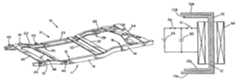
- FIG. 1is a schematic perspective view of a first embodiment of a vehicle frame manufactured in accordance with the method and apparatus of this invention.
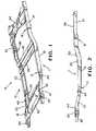
- FIG. 2is a side elevational view of one of the side rails of the vehicle frame illustrated in FIG. 1 , together with a number of brackets joined therewith, the side rail being formed from a plurality of individual side rail sections joined at overlap joints.
- FIG. 3is an enlarged perspective view of one of the overlap joints between two of the individual side rail sections illustrated in FIG. 2 .
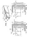
- FIG. 4is a sectional elevational view of the two individual side rail sections illustrated in FIG. 3 prior to being joined together.
- FIG. 5is a sectional elevational view similar to FIG. 4 of the two individual side rail sections illustrated in FIG. 3 after being joined together.
- FIG. 6is an enlarged perspective view of a portion of one of the side rails illustrated in FIG. 1 having a bracket joined thereto.
- FIG. 7is a sectional elevational view of the side rail and bracket illustrated in FIG. 6 prior to being joined together.
- FIG. 8is a sectional elevational view similar to FIG. 7 of the side rail and bracket illustrated in FIG. 6 after being joined together.
- FIG. 9is a perspective view similar to FIG. 6 of an alternative structure for securing the side rail and bracket together.
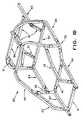
- FIG. 10is a schematic perspective view of a second embodiment of a vehicle frame manufactured in accordance with the method and apparatus of this invention, including a plurality of structural members which are joined together at joints by a plurality of joint nodes.
- FIG. 11is an exploded perspective view of a portion of the vehicle frame illustrated in FIG. 10 .
- FIG. 12is a perspective view of one of the straight members illustrated in FIGS. 10 and 11 .
- FIG. 13is a perspective view of one of the curved members illustrated in FIGS. 10 and 11 .
- FIG. 14is a perspective view of one of the joint nodes illustrated in FIGS. 10 and 11 .
- FIG. 15is a perspective view of one of the member nodes illustrated in FIGS. 10 and 11 .
- FIG. 16is a flowchart which illustrates the steps in a hydroforming process for forming the structural components illustrated in FIGS. 12 , 13 , 14 , and 15 .
- FIG. 17is a sectional elevational view of one of the joints between a straight member and a joint node illustrated in FIGS. 10 and 11 prior to being joined together.
- FIG. 18is a sectional elevational view similar to FIG. 17 of the joint between a straight member and a joint node illustrated in FIGS. 10 and 11 after being joined together.
- FIG. 19is a schematic perspective view of a third embodiment of a vehicle frame manufactured in accordance with the method and apparatus of this invention.
- FIG. 20is a sectional elevational view of one of the joints between two of the side rail sections illustrated in FIG. 19 prior to being joined together.
- FIG. 21is a sectional elevational view similar to FIG. 20 of the joint between two of the side rail sections illustrated in FIG. 19 after being joined together.
- FIG. 22illustrates a first alternative embodiment of the joint between the side rail sections illustrated in FIGS. 19 , 20 , and 21 .
- FIG. 23illustrates a second alternative embodiment of the joint between the side rail sections illustrated in FIGS. 19 , 20 , and 21 .
- FIG. 24is a sectional elevational view taken along line 24 — 24 of FIG. 19 illustrating a first embodiment of a joint between a side rail and a cross member.
- FIG. 25is a sectional elevational view similar to FIG. 24 illustrating a second embodiment of a joint between a side rail and a cross member.
- FIG. 26is a sectional elevational view similar to FIG. 24 illustrating a third embodiment of a joint between a side rail and a cross member.
- FIG. 27is a sectional elevational view similar to FIG. 24 illustrating a fourth embodiment of a joint between a side rail and a cross member.
- FIG. 28is a sectional elevational view similar to FIG. 24 illustrating a fifth embodiment of a joint between a side rail and a cross member.
- FIG. 1a first embodiment of a vehicle frame, indicated generally at 10 , which has been manufactured in accordance with the method and apparatus of this invention.
- the frame 10includes a first side rail, indicated generally at 11 , which extends longitudinally throughout the length of the vehicle in which it is to be used.
- the first side rail 11is formed from three individual side rail sections 12 , 13 , and 14 .
- the first and second side rail sections 12 and 13are joined at an overlap joint, indicated generally at 15 .
- the second and third side rail sections 13 and 14are joined at an overlap joint, indicated generally at 16 .
- the frame 10further includes a second side rail, indicated generally at 21 , which also extends longitudinally throughout the length of the vehicle in which it is to be used.
- the second side rail 21is formed in a similar manner as the first side rail 11 , including first, second, and third individual side rail sections 22 , 23 , and 24 which are joined at overlap joints 25 and 26 .
- the side rails 11 and 21are joined together by a plurality of transversely extending cross members 30 , 31 , 32 , 33 , and 34 .
- These cross members 30 through 34vary in size and shape and are intended to represent any type of cross member, cradle, or other structure which extends between the two side rails 11 and 21 .
- the basic structures of cross member of this typeare well known in the art.
- a plurality of brackets 40 , 41 , 42 , 43 , 44 , and 45are joined to the side rails 11 and 21 .
- These brackets 40 through 45also vary in size and shape and are intended to represent any type of bracket, hanger, or other structure which is joined to the side rails 11 and 21 .
- the basic structures of these bracketsare also well known in the art.
- the various components of the vehicle frame 10 discussed aboveare all formed from metallic materials.
- steelhas been found to be an acceptable material to form these various components.
- this inventioncontemplates that other metallic materials may be used, such as aluminum, magnesium, and the like may be used.
- all of the various components of the vehicle frame 10need not be formed from the same metallic material. Rather, some of such components may be formed from a first metallic material, while others may be formed from a second metallic material.
- the vehicle frame 10is formed by joining the various side rails 11 and 21 , cross members 30 through 34 , and brackets 40 through 45 together. Some of these components may be joined together by the use of mechanical fasteners, such as bolts, if desired. However, this invention relates to a method and apparatus for permanently joining these components together using a magnetic impulse welding techniques, which will be described below. Magnetic impulse welding techniques have been found to be preferable to conventional welding techniques in the formation of vehicle frames, as discussed above.
- FIG. 3there is illustrated an enlarged perspective view of the overlap joint 15 between the ends of the individual side rail sections 12 and 13 illustrated in FIGS. 1 and 2 .
- the rearward end of the first side rail section 12includes a vertically extending web portion having an upper horizontal flange portion 12 a and a lower horizontal flange portion 12 b extending therefrom.
- the forward end of the second side rail section 13includes a vertically extending web portion having an upper horizontal flange portion 13 a and a lower horizontal flange portion 13 b extending therefrom.
- first and second side rail sections 12 and 13are shown as having generally open channel or C-shaped cross sectional shapes, it will be appreciated that they may be formed having other cross sectional shapes. Also, it will be appreciated that the cross sectional shapes of the first and second side rail sections 12 and 13 need not be uniform throughout their entire lengths, nor does the cross sectional shape of the first side rail section 12 have to be the same as the cross sectional shape of the second side rail section 13 .
- the first side rail section 12is initially formed slightly smaller in size than the second side rail section 13 , prior to being joined together.
- the first side rail section 12may initially be disposed telescopically within the second side rail section 13 with clearance, as shown in FIG. 4 .
- the vertically extending web portions of the side rail sections 12 and 13are disposed generally parallel and adjacent to one another, as are the upper horizontal flange portions 12 a and 13 a and the lower horizontal flange portions 12 b and 13 b .
- the clearance between the respective portions of the side rail sections 12 and 13may be adjusted as desired, it has been found acceptable to provide a clearance in the range of from 0.050 inch to 0.100 inch.
- An electromagnetic coil 50is provided for generating a magnetic field which, as will be explained further below, causes the side rail sections 12 and 13 to move toward one another. Portions of the electromagnetic coil 50 are disposed on either side of the side rail sections 12 and 13 .
- the electromagnetic coil 50is embodied as a plurality of windings of an electrical conductor. A first end of the electrical conductor is connected through a first switch 51 to a first side of a capacitor 52 , while a second end of the electrical conductor is connected directly to a second side of the capacitor 52 .
- the capacitor 52is representative of a number of high voltage capacitors which are connected together in parallel.
- a source of electrical energy 53is provided for selectively charging the capacitor 52 to store a quantity of electrical energy therein. A first side of the source of electrical energy 53 is connected through a second switch 54 to the first side of the capacitor 52 , while a second side of the source of electrical energy 53 is connected directly to the second side of the capacitor 52 .
- the first switch 51is initially opened and the second switch 54 is initially closed, as shown in FIG. 4 .
- electrical energyis transferred from the source of electrical energy 53 into the capacitor 52 .
- the second switch 54is opened and the first switch 51 is closed, as shown in FIG. 5 .
- By closing the first switch 51energy in the form of electrical current is discharged from the capacitor 52 through the electromagnetic coil 50 .
- an intense electromagnetic fieldis generated about the first and second side rail sections.
- the presence of this electromagnetic fieldinduces electrical currents in the first and second side rail sections 12 and 13 .
- These electrical currentscreate opposing magnetic fields which draw the first and second side rail sections 12 and 13 into contact with one another. When this occurs, a large pressure exerted on the first and second side rail sections 12 and 13 move them toward one another at a high velocity.
- the sizes and shapes of the side rail sections 12 and 13 , the size and shape of the electromagnetic coil 50 , and the strength of the electromagnetic fieldare all factors which will determine where the deformation of the first and second side rail sections 12 and 13 will occur, as well as which portions thereof will be joined together.
- the first side rail section 12includes the vertically extending web portion having the upper horizontal flange portion 12 a and the lower horizontal flange portion 12 b extending therefrom.
- the bracket 45is formed having a vertically extending web portion having an upper horizontal flange portion 45 a extending therefrom.
- the vertically extending web portions of the first side rail section 12 and the bracket 45are disposed in spaced apart relationship, generally parallel and adjacent to one another as shown in FIG. 7 .
- Portions of the electromagnetic coil 50are disposed on either side of the side rail section 12 and the bracket 45 .
- the operation of the electromagnetic coil 50is the same as described above, and functions to weld or molecularly bond the side rail section 12 with the bracket 45 , as shown in FIG. 8 .
- FIG. 9illustrates an alternative structure for securing the side rail 12 and the bracket 45 together.
- the coil 50is disposed concentrically about an elongated cylindrical mandrel 46 .
- the mandrel 46is formed from a material which, when a magnetic field is generated by energization of the electromagnetic coil 50 , is urged for movement in the direction indicated by the arrow.
- One end of the mandrel 46is located adjacent to the vertically extending web portion of the bracket 45 .
- the bracket 45may be secured to the end of the mandrel 45 or may simply be disposed adjacent thereto.
- the bracket 45is welded or molecularly bonded to the side rail 12 similarly as described above.
- the side rails 11 and 12 described aboveare all shown as being formed from open channel stock, i.e., stock which has a non-closed cross sectional shape.
- the specifically illustrated side rails 11 and 12are formed having a generally open C-shaped cross section. It will be appreciated that this invention may be practiced using open channel stock having other cross sectional shapes.
- the side rails 11 and 12may be formed having a generally closed C-shaped cross section (wherein short flanges are provided at the ends of the illustrated side rails 11 and 12 which extend inwardly toward one another), a generally hat-shaped cross section (wherein short flanges are provided at the ends of the illustrated side rails 11 and 12 which extend outwardly apart from one another), or other open channel configurations.
- the illustrated vehicle frame assembly 60is an automobile space frame, i.e., a frame for an automobile which defines an enclosed space for occupants.
- this inventionmay be utilized in a flat bed frame or any other frame structure for any type of vehicle.
- the illustrated vehicle frame assembly 60is composed of four different types of structural components which are secured together.
- the first type of structural componentis referred to as a straight member, such as shown at 61 .
- Straight members 61are characterized as being linear and elongated in shape.
- the straight members 61are hollow and can be formed having any desired cross sectional shape.
- a straight member 61may be formed having a central portion 61 a which is square or rectangular in cross sectional shape and a pair of end portions 61 b which are circular in cross sectional shape.
- the square or rectangular cross sectional shape of the central portion 61 a of the straight member 61is desirable because it provides stiffness to the straight member 61 and facilitates the attachment of other components thereto, such as brackets and the like.
- the circular cross sectional shape of the end portions 61 b of the straight member 61is desirable because it facilitates the attachment of other structural components of the vehicle frame assembly 60 .
- the second type of structural component in the vehicle frame assembly 60is referred to as a curved member, such as shown at 62 .
- Curved members 62are similar to straight members 61 in that they are hollow and elongated. However, curved members 62 are not linear in shape like the straight members 61 , but rather extend non-linearly.
- a curved member 62may be formed having a single bend portion 62 a which is located between two linear portions 62 b .
- the curved member 62may be formed having a plurality of bend portions 62 a separating adjacent linear portions 62 b , or it may be curved along its entire length.
- the linear portions 62 b near the center of the curved member 62are square or rectangular in cross sectional shape.
- Two end portions 62 care provided on the curved member 62 which are circular in cross sectional shape, also for the same reasons as stated above.
- the third type of structural component in the vehicle frame assembly 60is referred to as a joint node, such as shown at 63 .
- Joint nodes 63are characterized as relatively small components which are provided to join adjacent components of the vehicle frame assembly 60 at a joint.
- a joint node 63may be formed having a relatively small body portion 63 a with a plurality (three in the illustrated embodiment) relatively short joint portions 63 b extending outwardly therefrom.
- the joint portions 63 bare typically linear because of their relatively short length, although such is not required.
- the body portion 63 a and the joint portions 63 bare hollow and can be formed having any desired cross sectional shape.
- the body portion 63 a and adjacent areas of the joint portions 63 bare preferably square or rectangular in cross sectional shape.
- Two end portions 63 care provided on the joint member 63 which are circular in cross sectional shape, also for the same reasons as stated above.
- the fourth type of structural component in the vehicle frame assembly 60is referred to as a member node, such as shown at 64 .
- Member nodes 64are characterized as elongated components which are also provided to join adjacent components of the vehicle frame assembly 60 at a joint.
- a member node 64may be formed having an elongated central portion 64 a , a pair of end portions 64 b , and one or more (three in the illustrated embodiment) relatively short joint portions 64 c extending outwardly therefrom.
- the joint portions 64 care typically linear because of their relatively short length, although such is not required.
- the central portion 64 a , the end portions 64 b , and the joint portions 64 care hollow and can be formed having any desired cross sectional shape. Again, for the same reasons stated above with respect to the straight member 61 , the central portion 64 a and adjacent areas of the joint portions 64 c are preferably square or rectangular in cross sectional shape. End portions 62 d are provided on the curved member 62 which are circular in cross sectional shape, also for the same reasons as stated above.
- Each of the four types of structural components 61 , 62 , 63 , and 64 used to form the vehicle frame assembly 60is preferably formed by hydroforming techniques.
- Hydroformingis a metal deformation process which, generally speaking, utilizes high pressure fluid introduced within a closed workpiece to expand portions of the workpiece outwardly into conformance with an enclosing die.
- FIG. 16is a flowchart 70 which illustrates the steps in the hydroforming process of this invention for forming any one or all of the four types of structural components 61 , 62 , 63 , and 64 used to form the vehicle frame assembly 60 .
- the first step 71 in the hydroforming processis to provide a closed blank.
- the closed blankis a tubular blank having a uniform circular cross sectional shape and formed from a metallic material.
- metallic materialsuch as aluminum, magnesium, and the like, be used.
- steel and other heavier metallic materialsmay be used as well.
- pre-bend the tubular blank into a preform shapeas shown at 72 .
- Such pre-bendingis necessary when the final desired shape of the structural component is dramatically different from the initial shape of the tubular blank.
- pre-bendingmay not be required when forming a straight member 61 because of its generally linear shape, but may be required when forming a curved member 62 .
- Several pre-bending operationsmay be performed on a single blank, depending upon the final desired shape for the structural component. Following this pre-bending, the blank follows the general shape of the structural component to be formed, but still has a generally uniform circular cross sectional shape throughout its entire length.
- the pre-bending stepmay be performed on a conventional tube bending apparatus or other similar mechanism.
- the pre-bent blankis disposed within a hydroforming die, and highly pressurized fluid is introduced therein, as shown at 73 .
- the highly pressurized fluid within the pre-bent blankcauses portions thereof to expand outwardly into conformance with the enclosed hydroforming die.
- the portions of the structural members 61 , 62 , 63 , and 64 having the square or rectangular cross sectional shapes discussed abovecan be formed.
- various openings (not shown) or other structuresmay be formed on the structural components as desired, such as for facilitating the connection of other components (brackets, etc.) to the vehicle frame assembly 60 .
- the hydroforming stepcan be performed on any conventional hydroforming apparatus.
- the final step in the process of forming the vehicle frame assemblyis to join the formed structural members together, as shown at 74 in the flowchart 70 .
- FIGS. 17 and 18the formation of a joint between one of the straight members 61 and one of the joint nodes 63 is illustrated.
- the end portion 61 b of the straight member 61is initially formed slightly larger in size than the end portion 63 c of the joint portion 63 b of the joint node 63 , prior to being joined together.
- the end portion 63 c of the joint node 63may initially be disposed telescopically within the end portion 61 b of the straight member 61 with an annular clearance, as shown in FIG. 17 .
- the outer cylindrical surface of the end portion 63 c of the joint node 63is disposed generally concentric with the inner cylindrical surface of the end portion 61 b of the straight member 61 .
- the clearance between these cylindrical surfacesmay be adjusted as desired, it has been found acceptable to provide a clearance in the range of from 0.050 inch to 0.100 inch.
- An electromagnetic coil 80is provided for generating a magnetic field which, as will be explained further below, causes the end portion 63 c of the joint node 63 and the end portion 61 b of the straight member 61 to move toward one another.
- the electromagnetic coil 80is disposed concentrically about the end portion 61 b of the straight member 61 .
- the electromagnetic coil 80is similar in structure and operation to the electromagnetic coil 50 described above, and the same control circuit may be used to operate same.
- the electromagnetic field generated by the coil 80causes the end portion 61 b of the straight member 61 to move toward the end portion 63 c of the joint node 63 at a high velocity.
- the end portion 61 b of the straight member 61 and the end portion 63 c of the joint node 63are welded or molecularly bonded as described above.
- the various components of the vehicle frame 60need not be formed from the same metallic material. Rather, some of such components may be formed from a first metallic material, while others may be formed from a second metallic material.
- the various structural components which are located in the upper portion of the vehicle frame assembly 60i.e., those structural components which extend upwardly from the bed portion of the vehicle frame assembly 60 to form the sides and roof of the passenger compartment
- the various structural components which are located in the lower portion of the vehicle frame assembly 60i.e., those structural components which form the bed portion of the vehicle frame assembly 60
- steelmay be used in portions of the vehicle frame assembly 60 in conjunction with either or both of the magnesium and aluminum materials.
- the above-described process for molecular bonding of vehicle frame components using magnetic impulse welding techniquesis advantageous because the adjacent dissimilar metals have been found not to cause corrosion when joined in this manner.
- FIG. 19there is illustrated a portion of a third embodiment of a full perimeter or ladder type vehicle frame assembly, indicated generally at 100 , in accordance with this invention.
- the illustrated vehicle frame assembly 100includes two longitudinally extending side rails, indicated generally at 111 and 112 , respectively.
- the illustrated side rails 111 and 112preferably extend throughout most or all of the length of the vehicle. However, it is also known to provide side rails 111 and 112 that extend throughout only a portion of the length of the vehicle.
- the side rails 111 and 112are each formed from a pair of relatively short side rail sections 111 a , 111 b and 112 a , 112 b , respectively, that are secured together at respective joints, indicated generally at 111 c and 112 c , in a manner described in detail below.
- the illustrated side rails sections 111 a , 111 b , 112 a , and 112 bare each formed from hollow members having a generally rectangular or box-shaped cross sectional shape.
- This cross sectional shapeis advantageous not only because it provides strength and rigidity, but also because it provides vertically and horizontally oriented side surfaces that facilitate the attachment of various brackets and mounts (not shown) used to support other components of the vehicle on the vehicle frame structure 100 .
- the side rails 111 and 112are formed from closed channel stock having a square or rectangular cross sectional shape.
- the side rails 111 and 112may be formed from tubular stock having a generally circular or other cross sectional shape.
- the side rails 111 and 112are formed from the same metallic material, such as steel. However, other materials, such as aluminum, magnesium, and the like, as well as combinations thereof, may be used if desired.
- the side rail sections 111 a , 111 b , 112 a , and 112 bmay be formed into desired shapes in any conventional manner.
- hydroformingmay be used to form the side rail sections 111 a , 111 b , 112 a , and 112 b to have the illustrated generally rectangular cross sectional and longitudinal shape.
- Hydroformingis a well known process that uses pressurized fluid to deform, expand, or re-shape a tubular member into a desired shape. In a known high pressure hydroforming process, the tubular member is initially disposed between two die sections of a hydroforming apparatus which, when closed together, define a die cavity having a desired final shape.
- the closure of the two die sectionsmay, in some instances, cause some mechanical deformation of the tubular member.
- the tubular memberis filled with a pressurized fluid, typically a relatively incompressible liquid such as water.
- the pressure of the fluidis increased to a magnitude where the tubular member is expanded outwardly into conformance with the die cavity.
- the tubular memberis expanded into the desired final shape.
- the tubular memberis initially filled with fluid at a relatively low pressure.
- the tubular memberis disposed between two die sections of a hydroforming apparatus which, when closed together, define a die cavity having a desired final shape.
- One or more cross membersextend transversely between the side rails 111 and 112 to form the vehicle frame assembly 100 upon which the remainder of the vehicle is supported.
- three of such cross member 113are extend transversely at the front, center, and rear portions of the vehicle frame assembly 100 .
- any desired number of cross members 113may be provided.
- Each of the cross members 113is preferably formed from a single relatively long piece of material that extends completely between the side rails 111 and 112 .
- the cross members 113may be formed from two or more relatively short pieces of material that are secured together. The method by which the ends of the cross members 113 are secured to the side rail 111 and 112 at respective joints, indicated generally at 114 , will be explained in detail below.
- the end portion of the side rail section 111 bis initially formed slightly larger in size than the end portion of the side rail section 111 a prior to being joined together.
- the end portion 63 c of the side rail section 111 amay initially be disposed telescopically within the end portion of the side rail section 111 b , as shown in FIG. 20 .
- the outer surface of the end portion of the side rail section 111 ais disposed in a spaced apart relationship with the inner surface of the end portion of the side rail section 111 b .
- the clearance between these surfacesmay be adjusted as desired, it has been found acceptable to provide a clearance in the range of from 0.050 inch to 0.100 inch.
- An electromagnetic coil 180is provided for generating a magnetic field which, as will be explained further below, causes the end portion of the side rail section 111 a and the end portion of the side rail section 111 b to move toward one another.
- the electromagnetic coil 180is disposed about the telescoping end portions of the side rail sections 111 a and 111 b .
- the electromagnetic coil 180is similar in structure and operation to the electromagnetic coil 50 described above, and the same control circuit may be used to operate same.
- the electromagnetic field generated by the coil 180causes the end portion of the side rail section 111 b to move toward the end portion of the side rail section 111 a at a high velocity.
- the end portion of the side rail section 111 b and the end portion of the side rail section 111 aare welded or molecularly bonded as described above.
- FIGS. 22 and 23illustrate two alternative embodiments of the joint 111 c illustrated in FIGS. 19 , 20 , and 21 .
- the closed channel side rail 111 ahas been replaced by an open channel side rail section 111 a′ having a generally U-shaped cross section to form a first modified joint 111 c ′.
- the closed channel side rail 111 ahas been replaced by an open channel side rail section 111 a ′′ having a generally C-shaped cross section to form a second modified joint 111 c ′′.
- the coil 180causes the end portion of the side rail section 111 b to become welded or molecularly bonded to the end portion of the side rail section 111 a ′ or 111 a ′′ as described above.
- FIGS. 24 through 28illustrate a number of alternative embodiments of the joint 114 between a side rail and a cross member.
- the side rail section 112 bhas an inwardly extending boss 115 formed with the inner side wall thereof.
- the boss 115can be formed by any conventional method, such as by hydroforming.
- the end of the cross member 113is sized to fit over the boss 115 initially with some clearance. Then, using the coil 180 described above, the end of the cross member 113 can be deformed into engagement with the boss 115 so as to become welded or molecularly bonded thereto as described above.
- a modified side rail section 112 b ′has an outwardly extending flange 116 formed with the outer side wall thereof and an inwardly extending flange 117 formed with the inner side wall thereof.
- the flanges 116 and 117can be formed by any conventional method, such as by hydroforming, and define an opening through the modified side rail 112 ′.
- the end of the cross member 113is inserted through the opening so as to initially have with some clearance with each of the flanges 116 and 117 .
- the flanges 116 and 117can be deformed into engagement with the end of the cross member 113 so as to become welded or molecularly bonded thereto as described above. If desired, only one of the flanges 116 and 117 may be formed on the side rail section 112 b ′ and secured to the cross member 113 .
- a modified cross member 113 ′includes a generally rectangular end portion having a plurality of outwardly extending tabs 113 a ′ formed thereon.
- the tabs 113 a ′are initially oriented in a generally parallel and spaced apart relationship relative to the adjacent portions of the side rail section 112 b . Then, using the coil 180 described above, each of the tabs 113 a ′ can be deformed into engagement with the adjacent portions of the side rail section 112 b so as to become welded or molecularly bonded thereto as described above.
- four of such tabs 113 a ′are illustrated, it will be appreciated that a lesser number of such tabs 113 a ′ may be provided and secured to the side rail section 112 b.
- a further modified cross member 113 ′′is formed having a generally C-shaped or U-shaped cross section.
- the cross member 113 ′′includes a generally rectangular end portion having a plurality of outwardly extending tabs 113 a ′′ formed thereon.
- the tabs 113 a ′′are initially oriented in a generally parallel and spaced apart relationship relative to the adjacent portions of the side rail section 112 b . Then, using the coil 180 described above, each of the tabs 113 a ′′ can be deformed into engagement with the adjacent portions of the side rail section 112 b so as to become welded or molecularly bonded thereto as described above.
- three of such tabs 113 a ′′are illustrated, it will be appreciated that a lesser number of such tabs 113 a ′′ may be provided and secured to the side rail section 112 b.
- a modified side rail section 112 b ′′is formed having a generally C-shaped or U-shaped cross section.
- the modified cross member 113 ′′is formed having a generally C-shaped or U-shaped cross section.
- the cross member 113 ′′includes a generally rectangular end portion having a plurality of outwardly extending tabs 113 a ′′ formed thereon.
- the tabs 113 a ′′are initially oriented in a generally parallel and spaced apart relationship relative to the adjacent portions of the side rail section 112 b ′′.
- each of the tabs 113 a ′′can be deformed into engagement with the adjacent portions of the side rail section 112 b ′′ so as to become welded or molecularly bonded thereto as described above.
- three of such tabs 113 a ′′are illustrated, it will be appreciated that a lesser number of such tabs 113 a ′′ may be provided and secured to the side rail section 112 b′′.
Landscapes
- Engineering & Computer Science (AREA)
- Mechanical Engineering (AREA)
- Chemical & Material Sciences (AREA)
- Combustion & Propulsion (AREA)
- Transportation (AREA)
- Physics & Mathematics (AREA)
- Plasma & Fusion (AREA)
- Body Structure For Vehicles (AREA)
Abstract
Description
Claims (15)
Priority Applications (1)
| Application Number | Priority Date | Filing Date | Title |
|---|---|---|---|
| US10/978,916US6977361B2 (en) | 1995-06-16 | 2004-11-01 | Molecular bonding of vehicle frame components using magnetic impulse welding techniques |
Applications Claiming Priority (6)
| Application Number | Priority Date | Filing Date | Title |
|---|---|---|---|
| US49128495A | 1995-06-16 | 1995-06-16 | |
| US08/666,063US6104012A (en) | 1995-06-16 | 1996-06-14 | Molecular bonding of vehicle frame components using magnetic impulse welding techniques |
| US09/138,597US6234375B1 (en) | 1995-06-16 | 1998-08-22 | Molecular bonding of vehicle frame components using magnetic impulse welding techniques |
| US09/862,033US6548792B1 (en) | 1995-06-16 | 2001-05-21 | Molecular bonding of vehicle frame components using magnetic impulse welding techniques |
| US10/414,466US6812439B1 (en) | 1995-06-16 | 2003-04-15 | Molecular bonding of vehicle frame components using magnetic impulse welding techniques |
| US10/978,916US6977361B2 (en) | 1995-06-16 | 2004-11-01 | Molecular bonding of vehicle frame components using magnetic impulse welding techniques |
Related Parent Applications (1)
| Application Number | Title | Priority Date | Filing Date |
|---|---|---|---|
| US10/414,466DivisionUS6812439B1 (en) | 1995-06-16 | 2003-04-15 | Molecular bonding of vehicle frame components using magnetic impulse welding techniques |
Publications (2)
| Publication Number | Publication Date |
|---|---|
| US20050116011A1 US20050116011A1 (en) | 2005-06-02 |
| US6977361B2true US6977361B2 (en) | 2005-12-20 |
Family
ID=33304069
Family Applications (2)
| Application Number | Title | Priority Date | Filing Date |
|---|---|---|---|
| US10/414,466Expired - Fee RelatedUS6812439B1 (en) | 1995-06-16 | 2003-04-15 | Molecular bonding of vehicle frame components using magnetic impulse welding techniques |
| US10/978,916Expired - LifetimeUS6977361B2 (en) | 1995-06-16 | 2004-11-01 | Molecular bonding of vehicle frame components using magnetic impulse welding techniques |
Family Applications Before (1)
| Application Number | Title | Priority Date | Filing Date |
|---|---|---|---|
| US10/414,466Expired - Fee RelatedUS6812439B1 (en) | 1995-06-16 | 2003-04-15 | Molecular bonding of vehicle frame components using magnetic impulse welding techniques |
Country Status (1)
| Country | Link |
|---|---|
| US (2) | US6812439B1 (en) |
Cited By (5)
| Publication number | Priority date | Publication date | Assignee | Title |
|---|---|---|---|---|
| US20060032895A1 (en)* | 2002-12-16 | 2006-02-16 | Robert Durand | Method for joining axle components |
| US20070218300A1 (en)* | 2006-03-14 | 2007-09-20 | Helmick David A | Method of applying a coating to an article via magnetic pulse welding |
| US20100242284A1 (en)* | 2009-03-31 | 2010-09-30 | Gm Global Technology Operations, Inc. | Mixed metal magnetic pulse impact beam |
| US20130002011A1 (en)* | 2011-06-30 | 2013-01-03 | Robert Lee Meyer | Track pin retention system |
| US20140062132A1 (en)* | 2012-09-03 | 2014-03-06 | Edward Schleichert | Impact Beam |
Families Citing this family (12)
| Publication number | Priority date | Publication date | Assignee | Title |
|---|---|---|---|---|
| US6812439B1 (en)* | 1995-06-16 | 2004-11-02 | Dana Corporation | Molecular bonding of vehicle frame components using magnetic impulse welding techniques |
| US7127816B2 (en)* | 2004-03-04 | 2006-10-31 | Dana Corporation | Method of permanently joining first and second metallic components |
| FR2883784B1 (en)* | 2005-03-31 | 2008-10-03 | Renault Sas | TOOL AND METHOD FOR ASSEMBLING METALLIC PARTS |
| US7941907B2 (en)* | 2006-10-31 | 2011-05-17 | GM Global Technology Operations LLC | Method for manufacture of shaped tubular part |
| EP1935551B1 (en)* | 2006-12-18 | 2011-06-29 | GM Global Technology Operations, Inc. | Method of magnetic impulse welding of sheets, one of the sheets having at least one attachment region inclined at an angle to the sheet plane |
| KR20120016630A (en)* | 2009-04-16 | 2012-02-24 | 다비데 바이아 | Welding head for rail welding |
| DE102009002958A1 (en)* | 2009-05-08 | 2010-11-11 | Robert Bosch Gmbh | Wiper-linkage device, manufacturing method therefor and windscreen wiper device |
| DE102011006364A1 (en)* | 2010-12-06 | 2013-03-21 | Brose Fahrzeugteile Gmbh & Co. Kommanditgesellschaft, Coburg | Method for connecting a first component to a second component, use of electromagnetic pulse transformation for establishing a connection, motor vehicle seat, motor vehicle door and motor vehicle |
| DE102014102974A1 (en)* | 2014-03-06 | 2015-09-10 | Thyssenkrupp Steel Europe Ag | Method for customizing the shape of components |
| US9676054B2 (en) | 2014-08-08 | 2017-06-13 | Ford Global Technologies, Llc | Electrode cartridge for pulse welding |
| US9421636B2 (en) | 2014-12-19 | 2016-08-23 | Ford Global Technologies, Llc | Pulse joining cartridges |
| FR3065663B1 (en)* | 2017-04-28 | 2019-06-28 | Faurecia Automotive Composites | METHOD OF ASSEMBLING TWO PIECES OF DIFFERENT MATERIALS AND ASSEMBLY ARISING FROM THE ASSEMBLY PROCESS |
Citations (43)
| Publication number | Priority date | Publication date | Assignee | Title |
|---|---|---|---|---|
| US2895747A (en) | 1955-05-31 | 1959-07-21 | Standard Oil Co | Welded aluminum coated tubular member and method of making same |
| US3258573A (en) | 1963-06-13 | 1966-06-28 | Theodore J Morin | Welding and forming method and apparatus |
| US3313536A (en) | 1965-02-01 | 1967-04-11 | Gen Motors Corp | Shock absorber |
| US3417456A (en) | 1966-09-30 | 1968-12-24 | Army Usa | Method for pulse forming |
| US3520049A (en) | 1965-10-14 | 1970-07-14 | Dmitry Nikolaevich Lysenko | Method of pressure welding |
| US3528596A (en) | 1966-09-30 | 1970-09-15 | Us Army | Apparatus for pulse forming |
| US3590464A (en) | 1969-03-07 | 1971-07-06 | Gulf Energy & Environ Systems | Threaded fastener and method of making the same |
| US3603759A (en) | 1970-01-14 | 1971-09-07 | Ind Magnetics Inc | Welding and forming method |
| US3603760A (en) | 1968-03-05 | 1971-09-07 | Konstantin Konstantinovich Khr | Apparatus for effecting the magnetic-impulse welding and pressure working of metals, preferably for welding tubular-shaped parts |
| US3794805A (en) | 1971-07-02 | 1974-02-26 | W Rudd | Magnetic pulse welding using spaced proximity conductor |
| US3961739A (en) | 1972-04-17 | 1976-06-08 | Grumman Aerospace Corporation | Method of welding metals using stress waves |
| US4049937A (en) | 1976-03-08 | 1977-09-20 | Lev Timofeevich Khimenko | Inductor for working metals by pressure of pulsating magnetic field |
| US4129846A (en) | 1975-08-13 | 1978-12-12 | Yablochnikov B | Inductor for magnetic pulse working of tubular metal articles |
| US4144433A (en) | 1976-12-16 | 1979-03-13 | General Electric Company | Method for metal bonding |
| US4150274A (en) | 1975-11-10 | 1979-04-17 | Minin Vladilen E | Method for lap welding of skelps and device for effecting same |
| US4170887A (en) | 1977-08-10 | 1979-10-16 | Kharkovsky Politekhnichesky Institut | Inductor for working metals by pressure of pulsating magnetic field |
| US4261092A (en) | 1979-09-20 | 1981-04-14 | Chrysler Corporation | Method of electroforming a metallic sleeve and ceramic shaft joint |
| US4334417A (en) | 1980-04-29 | 1982-06-15 | Etablissements Letang & Remy | Method for manufacturing vehicle-wheels by a magneto-forming process and wheels obtained by this method |
| US4504714A (en) | 1981-11-02 | 1985-03-12 | Jack Katzenstein | System and method for impact welding by magnetic propulsion |
| US4513188A (en) | 1981-10-20 | 1985-04-23 | Jack Katzenstein | System and method for impact welding by magnetic implosion |
| US4523872A (en) | 1981-08-12 | 1985-06-18 | Grumman Aerospace Corporation | Torsion resistant grooved joint |
| US4650947A (en) | 1985-02-18 | 1987-03-17 | Hutton Roger L | Induction tacking method and apparatus |
| US4789094A (en) | 1986-03-06 | 1988-12-06 | Institut Electrosvarki Imeni E.O. Patona | Device for alignment of cylindrical workpieces for magnetic-discharge welding |
| US4807351A (en) | 1988-02-18 | 1989-02-28 | Asea Composites, Inc. | Method for attaching an end-fitting to a drive shaft tube |
| US4885215A (en) | 1986-10-01 | 1989-12-05 | Kawasaki Steel Corp. | Zn-coated stainless steel welded pipe |
| US4922075A (en) | 1986-07-11 | 1990-05-01 | Kabushi Kaisha Toyoda Jidoshokki Seisakusho | Electric resistance welding for zinc plated steel plate |
| US4930204A (en) | 1989-02-01 | 1990-06-05 | A. O. Smith Corporation | Method of forming composite tubular structure |
| US4950348A (en) | 1988-10-13 | 1990-08-21 | Elva Induksjon A/S | Method for joining structural elements by heating of a binder |
| US4950552A (en) | 1988-09-30 | 1990-08-21 | Union Oil Company Of California | Method for protecting stainless steel pipe and the like in geothermal brine service from stress corrosion cracking, and articles made thereby |
| US4990732A (en) | 1987-03-19 | 1991-02-05 | Dudko Daniil A | Discharge device for magnetic-pulse working and welding of metals |
| US5157969A (en) | 1989-11-29 | 1992-10-27 | Armco Steel Co., L.P. | Apparatus and method for hydroforming sheet metal |
| US5170557A (en) | 1991-05-01 | 1992-12-15 | Benteler Industries, Inc. | Method of forming a double wall, air gap exhaust duct component |
| US5326957A (en) | 1991-04-26 | 1994-07-05 | Fanuc Ltd. | Apparatus for and method of welding surface-treated metallic workpieces |
| US5339667A (en) | 1993-04-19 | 1994-08-23 | General Motors Corporation | Method for pinch free tube forming |
| US5442846A (en) | 1993-09-23 | 1995-08-22 | Snaper; Alvin A. | Procedure and apparatus for cold joining of metallic pipes |
| US5561902A (en) | 1994-09-28 | 1996-10-08 | Cosma International Inc. | Method of manufacturing a ladder frame assembly for a motor vehicle |
| US5882460A (en) | 1995-06-21 | 1999-03-16 | Dana Corporation | Method for manufacturing vehicle frame components using composite fiber pultrusion techniques |
| US5884722A (en) | 1997-01-23 | 1999-03-23 | Dana Corporation | Engine cradle for vehicle body and frame assembly and method of manufacturing same |
| US5966813A (en) | 1997-12-23 | 1999-10-19 | Dana Corporation | Method for joining vehicle frame components |
| US6104012A (en) | 1995-06-16 | 2000-08-15 | Dana Corporation | Molecular bonding of vehicle frame components using magnetic impulse welding techniques |
| US6234375B1 (en) | 1995-06-16 | 2001-05-22 | Dana Corporation | Molecular bonding of vehicle frame components using magnetic impulse welding techniques |
| US6255631B1 (en) | 1999-11-29 | 2001-07-03 | Dana Corporation | Apparatus and method for joining vehicle frame components |
| US6812439B1 (en)* | 1995-06-16 | 2004-11-02 | Dana Corporation | Molecular bonding of vehicle frame components using magnetic impulse welding techniques |
- 2003
- 2003-04-15USUS10/414,466patent/US6812439B1/ennot_activeExpired - Fee Related
- 2004
- 2004-11-01USUS10/978,916patent/US6977361B2/ennot_activeExpired - Lifetime
Patent Citations (44)
| Publication number | Priority date | Publication date | Assignee | Title |
|---|---|---|---|---|
| US2895747A (en) | 1955-05-31 | 1959-07-21 | Standard Oil Co | Welded aluminum coated tubular member and method of making same |
| US3258573A (en) | 1963-06-13 | 1966-06-28 | Theodore J Morin | Welding and forming method and apparatus |
| US3313536A (en) | 1965-02-01 | 1967-04-11 | Gen Motors Corp | Shock absorber |
| US3520049A (en) | 1965-10-14 | 1970-07-14 | Dmitry Nikolaevich Lysenko | Method of pressure welding |
| US3417456A (en) | 1966-09-30 | 1968-12-24 | Army Usa | Method for pulse forming |
| US3528596A (en) | 1966-09-30 | 1970-09-15 | Us Army | Apparatus for pulse forming |
| US3603760A (en) | 1968-03-05 | 1971-09-07 | Konstantin Konstantinovich Khr | Apparatus for effecting the magnetic-impulse welding and pressure working of metals, preferably for welding tubular-shaped parts |
| US3590464A (en) | 1969-03-07 | 1971-07-06 | Gulf Energy & Environ Systems | Threaded fastener and method of making the same |
| US3603759A (en) | 1970-01-14 | 1971-09-07 | Ind Magnetics Inc | Welding and forming method |
| US3794805A (en) | 1971-07-02 | 1974-02-26 | W Rudd | Magnetic pulse welding using spaced proximity conductor |
| US3961739A (en) | 1972-04-17 | 1976-06-08 | Grumman Aerospace Corporation | Method of welding metals using stress waves |
| US4129846A (en) | 1975-08-13 | 1978-12-12 | Yablochnikov B | Inductor for magnetic pulse working of tubular metal articles |
| US4150274A (en) | 1975-11-10 | 1979-04-17 | Minin Vladilen E | Method for lap welding of skelps and device for effecting same |
| US4049937A (en) | 1976-03-08 | 1977-09-20 | Lev Timofeevich Khimenko | Inductor for working metals by pressure of pulsating magnetic field |
| US4144433A (en) | 1976-12-16 | 1979-03-13 | General Electric Company | Method for metal bonding |
| US4170887A (en) | 1977-08-10 | 1979-10-16 | Kharkovsky Politekhnichesky Institut | Inductor for working metals by pressure of pulsating magnetic field |
| US4261092A (en) | 1979-09-20 | 1981-04-14 | Chrysler Corporation | Method of electroforming a metallic sleeve and ceramic shaft joint |
| US4334417A (en) | 1980-04-29 | 1982-06-15 | Etablissements Letang & Remy | Method for manufacturing vehicle-wheels by a magneto-forming process and wheels obtained by this method |
| US4523872A (en) | 1981-08-12 | 1985-06-18 | Grumman Aerospace Corporation | Torsion resistant grooved joint |
| US4513188A (en) | 1981-10-20 | 1985-04-23 | Jack Katzenstein | System and method for impact welding by magnetic implosion |
| US4504714A (en) | 1981-11-02 | 1985-03-12 | Jack Katzenstein | System and method for impact welding by magnetic propulsion |
| US4650947A (en) | 1985-02-18 | 1987-03-17 | Hutton Roger L | Induction tacking method and apparatus |
| US4789094A (en) | 1986-03-06 | 1988-12-06 | Institut Electrosvarki Imeni E.O. Patona | Device for alignment of cylindrical workpieces for magnetic-discharge welding |
| US4922075A (en) | 1986-07-11 | 1990-05-01 | Kabushi Kaisha Toyoda Jidoshokki Seisakusho | Electric resistance welding for zinc plated steel plate |
| US4885215A (en) | 1986-10-01 | 1989-12-05 | Kawasaki Steel Corp. | Zn-coated stainless steel welded pipe |
| US4990732A (en) | 1987-03-19 | 1991-02-05 | Dudko Daniil A | Discharge device for magnetic-pulse working and welding of metals |
| US4807351A (en) | 1988-02-18 | 1989-02-28 | Asea Composites, Inc. | Method for attaching an end-fitting to a drive shaft tube |
| US4950552A (en) | 1988-09-30 | 1990-08-21 | Union Oil Company Of California | Method for protecting stainless steel pipe and the like in geothermal brine service from stress corrosion cracking, and articles made thereby |
| US4950348A (en) | 1988-10-13 | 1990-08-21 | Elva Induksjon A/S | Method for joining structural elements by heating of a binder |
| US4930204A (en) | 1989-02-01 | 1990-06-05 | A. O. Smith Corporation | Method of forming composite tubular structure |
| US5157969A (en) | 1989-11-29 | 1992-10-27 | Armco Steel Co., L.P. | Apparatus and method for hydroforming sheet metal |
| US5326957A (en) | 1991-04-26 | 1994-07-05 | Fanuc Ltd. | Apparatus for and method of welding surface-treated metallic workpieces |
| US5170557A (en) | 1991-05-01 | 1992-12-15 | Benteler Industries, Inc. | Method of forming a double wall, air gap exhaust duct component |
| US5339667A (en) | 1993-04-19 | 1994-08-23 | General Motors Corporation | Method for pinch free tube forming |
| US5442846A (en) | 1993-09-23 | 1995-08-22 | Snaper; Alvin A. | Procedure and apparatus for cold joining of metallic pipes |
| US5561902A (en) | 1994-09-28 | 1996-10-08 | Cosma International Inc. | Method of manufacturing a ladder frame assembly for a motor vehicle |
| US6104012A (en) | 1995-06-16 | 2000-08-15 | Dana Corporation | Molecular bonding of vehicle frame components using magnetic impulse welding techniques |
| US6234375B1 (en) | 1995-06-16 | 2001-05-22 | Dana Corporation | Molecular bonding of vehicle frame components using magnetic impulse welding techniques |
| US6548792B1 (en) | 1995-06-16 | 2003-04-15 | Dana Corporation | Molecular bonding of vehicle frame components using magnetic impulse welding techniques |
| US6812439B1 (en)* | 1995-06-16 | 2004-11-02 | Dana Corporation | Molecular bonding of vehicle frame components using magnetic impulse welding techniques |
| US5882460A (en) | 1995-06-21 | 1999-03-16 | Dana Corporation | Method for manufacturing vehicle frame components using composite fiber pultrusion techniques |
| US5884722A (en) | 1997-01-23 | 1999-03-23 | Dana Corporation | Engine cradle for vehicle body and frame assembly and method of manufacturing same |
| US5966813A (en) | 1997-12-23 | 1999-10-19 | Dana Corporation | Method for joining vehicle frame components |
| US6255631B1 (en) | 1999-11-29 | 2001-07-03 | Dana Corporation | Apparatus and method for joining vehicle frame components |
Cited By (7)
| Publication number | Priority date | Publication date | Assignee | Title |
|---|---|---|---|---|
| US20060032895A1 (en)* | 2002-12-16 | 2006-02-16 | Robert Durand | Method for joining axle components |
| US7140530B2 (en)* | 2002-12-16 | 2006-11-28 | Dana Corporation | Method for joining axle components |
| US20070218300A1 (en)* | 2006-03-14 | 2007-09-20 | Helmick David A | Method of applying a coating to an article via magnetic pulse welding |
| US20100242284A1 (en)* | 2009-03-31 | 2010-09-30 | Gm Global Technology Operations, Inc. | Mixed metal magnetic pulse impact beam |
| US8360301B2 (en)* | 2009-03-31 | 2013-01-29 | GM Global Technology Operations LLC | Mixed metal magnetic pulse impact beam |
| US20130002011A1 (en)* | 2011-06-30 | 2013-01-03 | Robert Lee Meyer | Track pin retention system |
| US20140062132A1 (en)* | 2012-09-03 | 2014-03-06 | Edward Schleichert | Impact Beam |
Also Published As
| Publication number | Publication date |
|---|---|
| US6812439B1 (en) | 2004-11-02 |
| US20050116011A1 (en) | 2005-06-02 |
Similar Documents
| Publication | Publication Date | Title |
|---|---|---|
| US6548792B1 (en) | Molecular bonding of vehicle frame components using magnetic impulse welding techniques | |
| US6104012A (en) | Molecular bonding of vehicle frame components using magnetic impulse welding techniques | |
| US6977361B2 (en) | Molecular bonding of vehicle frame components using magnetic impulse welding techniques | |
| WO1997000595A1 (en) | Preparation of vehicle frame components for molecular bonding using magnetic impulse welding techniques | |
| US6255631B1 (en) | Apparatus and method for joining vehicle frame components | |
| US6533348B1 (en) | Modular space frame | |
| US6412818B1 (en) | Vehicle body and frame assembly and method of manufacturing same | |
| US7765699B2 (en) | Truck cab space frame | |
| EP1363826B1 (en) | Hybrid space frame for motor vehicle | |
| US5882039A (en) | Hydroformed engine cradle and cross member for vehicle body and frame assembly | |
| US6302478B1 (en) | Hydroformed space frame joints therefor | |
| US6477774B1 (en) | Method of manufacturing a vehicle frame assembly | |
| US6003935A (en) | Modular vehicle frame assembly | |
| US6138358A (en) | Method of manufacturing a vehicle body and frame assembly | |
| AU2001250219A1 (en) | Modular space frame | |
| US6681488B2 (en) | Method of manufacturing a vehicle body and frame assembly | |
| US6513242B1 (en) | Method of manufacturing a vehicle body and frame assembly including hydroformed side rails | |
| EP1204508A1 (en) | Molecular bonding of vehicle frame components using magnetic impulse welding techniques | |
| US6510920B1 (en) | Vehicle exhaust system and method of manufacture | |
| US6519855B1 (en) | Method of manufacturing a vehicle body and frame assembly | |
| US7614151B2 (en) | Method of securing a bracket to a frame assembly | |
| EP1083117B1 (en) | Method of manufacturing a vehicle frame assembly |
Legal Events
| Date | Code | Title | Description |
|---|---|---|---|
| AS | Assignment | Owner name:DANA CORPORATION, OHIO Free format text:ASSIGNMENT OF ASSIGNORS INTEREST;ASSIGNOR:DURAND, ROBERT D.;REEL/FRAME:015655/0295 Effective date:20050131 | |
| STCF | Information on status: patent grant | Free format text:PATENTED CASE | |
| AS | Assignment | Owner name:DANA AUTOMOTIVE SYSTEMS GROUP, LLC, OHIO Free format text:ASSIGNMENT OF ASSIGNORS INTEREST;ASSIGNOR:DANA CORPORATION;REEL/FRAME:020540/0476 Effective date:20080131 Owner name:DANA AUTOMOTIVE SYSTEMS GROUP, LLC,OHIO Free format text:ASSIGNMENT OF ASSIGNORS INTEREST;ASSIGNOR:DANA CORPORATION;REEL/FRAME:020540/0476 Effective date:20080131 | |
| AS | Assignment | Owner name:CITICORP USA, INC., NEW YORK Free format text:INTELLECTUAL PROPERTY TERM FACILITY SECURITY AGREEMENT;ASSIGNORS:DANA HOLDING CORPORATION;DANA LIMITED;DANA AUTOMOTIVE SYSTEMS GROUP, LLC;AND OTHERS;REEL/FRAME:020859/0359 Effective date:20080131 Owner name:CITICORP USA, INC., NEW YORK Free format text:INTELLECTUAL PROPERTY REVOLVING FACILITY SECURITY AGREEMENT;ASSIGNORS:DANA HOLDING CORPORATION;DANA LIMITED;DANA AUTOMOTIVE SYSTEMS GROUP, LLC;AND OTHERS;REEL/FRAME:020859/0249 Effective date:20080131 Owner name:CITICORP USA, INC.,NEW YORK Free format text:INTELLECTUAL PROPERTY REVOLVING FACILITY SECURITY AGREEMENT;ASSIGNORS:DANA HOLDING CORPORATION;DANA LIMITED;DANA AUTOMOTIVE SYSTEMS GROUP, LLC;AND OTHERS;REEL/FRAME:020859/0249 Effective date:20080131 Owner name:CITICORP USA, INC.,NEW YORK Free format text:INTELLECTUAL PROPERTY TERM FACILITY SECURITY AGREEMENT;ASSIGNORS:DANA HOLDING CORPORATION;DANA LIMITED;DANA AUTOMOTIVE SYSTEMS GROUP, LLC;AND OTHERS;REEL/FRAME:020859/0359 Effective date:20080131 | |
| FPAY | Fee payment | Year of fee payment:4 | |
| AS | Assignment | Owner name:DANA HOLDING CORPORATION,OHIO Free format text:RELEASE BY SECURED PARTY;ASSIGNOR:CITICORP USA, INC.;REEL/FRAME:024055/0498 Effective date:20100304 Owner name:DANA LIMITED,OHIO Free format text:RELEASE BY SECURED PARTY;ASSIGNOR:CITICORP USA, INC.;REEL/FRAME:024055/0498 Effective date:20100304 Owner name:DANA AUTOMOTIVE SYSTEMS GROUP, LLC,OHIO Free format text:RELEASE BY SECURED PARTY;ASSIGNOR:CITICORP USA, INC.;REEL/FRAME:024055/0498 Effective date:20100304 Owner name:DANA DRIVESHAFT PRODUCTS, LLC,OHIO Free format text:RELEASE BY SECURED PARTY;ASSIGNOR:CITICORP USA, INC.;REEL/FRAME:024055/0498 Effective date:20100304 Owner name:DANA DRIVESHAFT MANUFACTURING, LLC,OHIO Free format text:RELEASE BY SECURED PARTY;ASSIGNOR:CITICORP USA, INC.;REEL/FRAME:024055/0498 Effective date:20100304 Owner name:DANA LIGHT AXLE PRODUCTS, LLC,OHIO Free format text:RELEASE BY SECURED PARTY;ASSIGNOR:CITICORP USA, INC.;REEL/FRAME:024055/0498 Effective date:20100304 Owner name:DANA LIGHT AXLE MANUFACTURING, LLC,OHIO Free format text:RELEASE BY SECURED PARTY;ASSIGNOR:CITICORP USA, INC.;REEL/FRAME:024055/0498 Effective date:20100304 Owner name:DANA SEALING PRODUCTS, LLC,OHIO Free format text:RELEASE BY SECURED PARTY;ASSIGNOR:CITICORP USA, INC.;REEL/FRAME:024055/0498 Effective date:20100304 Owner name:DANA SEALING MANUFACTURING, LLC,OHIO Free format text:RELEASE BY SECURED PARTY;ASSIGNOR:CITICORP USA, INC.;REEL/FRAME:024055/0498 Effective date:20100304 Owner name:DANA STRUCTURAL PRODUCTS, LLC,OHIO Free format text:RELEASE BY SECURED PARTY;ASSIGNOR:CITICORP USA, INC.;REEL/FRAME:024055/0498 Effective date:20100304 Owner name:DANA THERMAL PRODUCTS, LLC,OHIO Free format text:RELEASE BY SECURED PARTY;ASSIGNOR:CITICORP USA, INC.;REEL/FRAME:024055/0498 Effective date:20100304 Owner name:DANA HEAVY VEHICLE SYSTEMS GROUP, LLC,OHIO Free format text:RELEASE BY SECURED PARTY;ASSIGNOR:CITICORP USA, INC.;REEL/FRAME:024055/0498 Effective date:20100304 Owner name:DANA COMMERCIAL VEHICLE PRODUCTS, LLC,OHIO Free format text:RELEASE BY SECURED PARTY;ASSIGNOR:CITICORP USA, INC.;REEL/FRAME:024055/0498 Effective date:20100304 Owner name:DANA COMMERCIAL VEHICLE MANUFACTURING, LLC,OHIO Free format text:RELEASE BY SECURED PARTY;ASSIGNOR:CITICORP USA, INC.;REEL/FRAME:024055/0498 Effective date:20100304 Owner name:DANA OFF HIGHWAY PRODUCTS, LLC,OHIO Free format text:RELEASE BY SECURED PARTY;ASSIGNOR:CITICORP USA, INC.;REEL/FRAME:024055/0498 Effective date:20100304 Owner name:DTF TRUCKING INC.,OHIO Free format text:RELEASE BY SECURED PARTY;ASSIGNOR:CITICORP USA, INC.;REEL/FRAME:024055/0498 Effective date:20100304 Owner name:DANA WORLD TRADE CORPORATION,OHIO Free format text:RELEASE BY SECURED PARTY;ASSIGNOR:CITICORP USA, INC.;REEL/FRAME:024055/0498 Effective date:20100304 Owner name:DANA AUTOMOTIVE AFTERMARKET, INC.,OHIO Free format text:RELEASE BY SECURED PARTY;ASSIGNOR:CITICORP USA, INC.;REEL/FRAME:024055/0498 Effective date:20100304 Owner name:DANA GLOBAL PRODUCTS, INC.,OHIO Free format text:RELEASE BY SECURED PARTY;ASSIGNOR:CITICORP USA, INC.;REEL/FRAME:024055/0498 Effective date:20100304 Owner name:DANA STRUCTUCTURAL MANUFACTURING, LLC,OHIO Free format text:RELEASE BY SECURED PARTY;ASSIGNOR:CITICORP USA, INC.;REEL/FRAME:024055/0498 Effective date:20100304 Owner name:SPICER HEAVY AXLE & BRAKE, INC.,OHIO Free format text:RELEASE BY SECURED PARTY;ASSIGNOR:CITICORP USA, INC.;REEL/FRAME:024055/0498 Effective date:20100304 | |
| AS | Assignment | Owner name:DANA HOLDING CORPORATION,OHIO Free format text:RELEASE BY SECURED PARTY;ASSIGNOR:CITICORP USA, INC.;REEL/FRAME:024055/0753 Effective date:20100304 Owner name:DANA LIMITED,OHIO Free format text:RELEASE BY SECURED PARTY;ASSIGNOR:CITICORP USA, INC.;REEL/FRAME:024055/0753 Effective date:20100304 Owner name:DANA AUTOMOTIVE SYSTEMS GROUP, LLC,OHIO Free format text:RELEASE BY SECURED PARTY;ASSIGNOR:CITICORP USA, INC.;REEL/FRAME:024055/0753 Effective date:20100304 Owner name:DANA DRIVESHAFT PRODUCTS, LLC,OHIO Free format text:RELEASE BY SECURED PARTY;ASSIGNOR:CITICORP USA, INC.;REEL/FRAME:024055/0753 Effective date:20100304 Owner name:DANA DRIVESHAFT MANUFACTURING, LLC,OHIO Free format text:RELEASE BY SECURED PARTY;ASSIGNOR:CITICORP USA, INC.;REEL/FRAME:024055/0753 Effective date:20100304 Owner name:DANA LIGHT AXLE PRODUCTS, LLC,OHIO Free format text:RELEASE BY SECURED PARTY;ASSIGNOR:CITICORP USA, INC.;REEL/FRAME:024055/0753 Effective date:20100304 Owner name:DANA LIGHT AXLE MANUFACTURING, LLC,OHIO Free format text:RELEASE BY SECURED PARTY;ASSIGNOR:CITICORP USA, INC.;REEL/FRAME:024055/0753 Effective date:20100304 Owner name:DANA SEALING PRODUCTS, LLC,OHIO Free format text:RELEASE BY SECURED PARTY;ASSIGNOR:CITICORP USA, INC.;REEL/FRAME:024055/0753 Effective date:20100304 Owner name:DANA SEALING MANUFACTURING, LLC,OHIO Free format text:RELEASE BY SECURED PARTY;ASSIGNOR:CITICORP USA, INC.;REEL/FRAME:024055/0753 Effective date:20100304 Owner name:DANA STRUCTURAL PRODUCTS, LLC,OHIO Free format text:RELEASE BY SECURED PARTY;ASSIGNOR:CITICORP USA, INC.;REEL/FRAME:024055/0753 Effective date:20100304 Owner name:DANA THERMAL PRODUCTS, LLC,OHIO Free format text:RELEASE BY SECURED PARTY;ASSIGNOR:CITICORP USA, INC.;REEL/FRAME:024055/0753 Effective date:20100304 Owner name:DANA HEAVY VEHICLE SYSTEMS GROUP, LLC,OHIO Free format text:RELEASE BY SECURED PARTY;ASSIGNOR:CITICORP USA, INC.;REEL/FRAME:024055/0753 Effective date:20100304 Owner name:DANA COMMERCIAL VEHICLE PRODUCTS, LLC,OHIO Free format text:RELEASE BY SECURED PARTY;ASSIGNOR:CITICORP USA, INC.;REEL/FRAME:024055/0753 Effective date:20100304 Owner name:DANA COMMERCIAL VEHICLE MANUFACTURING, LLC,OHIO Free format text:RELEASE BY SECURED PARTY;ASSIGNOR:CITICORP USA, INC.;REEL/FRAME:024055/0753 Effective date:20100304 Owner name:SPICER HEAVY AXLE & BRAKE, INC.,OHIO Free format text:RELEASE BY SECURED PARTY;ASSIGNOR:CITICORP USA, INC.;REEL/FRAME:024055/0753 Effective date:20100304 Owner name:DANA OFF HIGHWAY PRODUCTS, LLC,OHIO Free format text:RELEASE BY SECURED PARTY;ASSIGNOR:CITICORP USA, INC.;REEL/FRAME:024055/0753 Effective date:20100304 Owner name:DTF TRUCKING INC.,OHIO Free format text:RELEASE BY SECURED PARTY;ASSIGNOR:CITICORP USA, INC.;REEL/FRAME:024055/0753 Effective date:20100304 Owner name:DANA WORLD TRADE CORPORATION,OHIO Free format text:RELEASE BY SECURED PARTY;ASSIGNOR:CITICORP USA, INC.;REEL/FRAME:024055/0753 Effective date:20100304 Owner name:DANA AUTOMOTIVE AFTERMARKET, INC.,OHIO Free format text:RELEASE BY SECURED PARTY;ASSIGNOR:CITICORP USA, INC.;REEL/FRAME:024055/0753 Effective date:20100304 Owner name:DANA GLOBAL PRODUCTS, INC.,OHIO Free format text:RELEASE BY SECURED PARTY;ASSIGNOR:CITICORP USA, INC.;REEL/FRAME:024055/0753 Effective date:20100304 Owner name:DANA STRUCTURAL MANUFACTURING, LLC,OHIO Free format text:RELEASE BY SECURED PARTY;ASSIGNOR:CITICORP USA, INC.;REEL/FRAME:024055/0753 Effective date:20100304 | |
| AS | Assignment | Owner name:METALSA S. A. DE C.V.,MEXICO Free format text:ASSIGNMENT OF ASSIGNORS INTEREST;ASSIGNOR:DANAAUTOMOTIVE SYSTEMS GROUP, LLC;REEL/FRAME:024151/0335 Effective date:20100308 | |
| FPAY | Fee payment | Year of fee payment:8 | |
| FPAY | Fee payment | Year of fee payment:12 |