US6976699B2 - Coordinated articulation of wheelchair members - Google Patents
Coordinated articulation of wheelchair membersDownload PDFInfo
- Publication number
- US6976699B2 US6976699B2US10/616,465US61646503AUS6976699B2US 6976699 B2US6976699 B2US 6976699B2US 61646503 AUS61646503 AUS 61646503AUS 6976699 B2US6976699 B2US 6976699B2
- Authority
- US
- United States
- Prior art keywords
- wheelchair
- controller
- articulated
- sequence
- articulated member
- Prior art date
- Legal status (The legal status is an assumption and is not a legal conclusion. Google has not performed a legal analysis and makes no representation as to the accuracy of the status listed.)
- Expired - Lifetime, expires
Links
- 230000033001locomotionEffects0.000claimsabstractdescription56
- 230000004044responseEffects0.000claimsdescription10
- 230000001133accelerationEffects0.000claimsdescription6
- 230000008093supporting effectEffects0.000claimsdescription6
- 238000000034methodMethods0.000description32
- 230000006870functionEffects0.000description30
- 210000002414legAnatomy0.000description24
- 230000008569processEffects0.000description12
- 230000007246mechanismEffects0.000description5
- 230000009471actionEffects0.000description3
- 230000003213activating effectEffects0.000description3
- 230000008901benefitEffects0.000description3
- 230000000977initiatory effectEffects0.000description3
- 230000004913activationEffects0.000description2
- 230000001976improved effectEffects0.000description2
- 235000014676Phragmites communisNutrition0.000description1
- 208000025865UlcerDiseases0.000description1
- 230000017531blood circulationEffects0.000description1
- 230000037396body weightEffects0.000description1
- 210000001217buttockAnatomy0.000description1
- 230000008859changeEffects0.000description1
- 238000010586diagramMethods0.000description1
- 238000006073displacement reactionMethods0.000description1
- 238000005259measurementMethods0.000description1
- 230000000116mitigating effectEffects0.000description1
- 230000011664signalingEffects0.000description1
- 231100000397ulcerToxicity0.000description1
Images


Classifications
- A—HUMAN NECESSITIES
- A61—MEDICAL OR VETERINARY SCIENCE; HYGIENE
- A61G—TRANSPORT, PERSONAL CONVEYANCES, OR ACCOMMODATION SPECIALLY ADAPTED FOR PATIENTS OR DISABLED PERSONS; OPERATING TABLES OR CHAIRS; CHAIRS FOR DENTISTRY; FUNERAL DEVICES
- A61G5/00—Chairs or personal conveyances specially adapted for patients or disabled persons, e.g. wheelchairs
- A61G5/10—Parts, details or accessories
- A61G5/1056—Arrangements for adjusting the seat
- A61G5/107—Arrangements for adjusting the seat positioning the whole seat forward or rearward
- A—HUMAN NECESSITIES
- A61—MEDICAL OR VETERINARY SCIENCE; HYGIENE
- A61G—TRANSPORT, PERSONAL CONVEYANCES, OR ACCOMMODATION SPECIALLY ADAPTED FOR PATIENTS OR DISABLED PERSONS; OPERATING TABLES OR CHAIRS; CHAIRS FOR DENTISTRY; FUNERAL DEVICES
- A61G5/00—Chairs or personal conveyances specially adapted for patients or disabled persons, e.g. wheelchairs
- A61G5/006—Chairs or personal conveyances specially adapted for patients or disabled persons, e.g. wheelchairs convertible to stretchers or beds
- A—HUMAN NECESSITIES
- A61—MEDICAL OR VETERINARY SCIENCE; HYGIENE
- A61G—TRANSPORT, PERSONAL CONVEYANCES, OR ACCOMMODATION SPECIALLY ADAPTED FOR PATIENTS OR DISABLED PERSONS; OPERATING TABLES OR CHAIRS; CHAIRS FOR DENTISTRY; FUNERAL DEVICES
- A61G5/00—Chairs or personal conveyances specially adapted for patients or disabled persons, e.g. wheelchairs
- A61G5/10—Parts, details or accessories
- A61G5/1056—Arrangements for adjusting the seat
- A61G5/1067—Arrangements for adjusting the seat adjusting the backrest relative to the seat portion
- A—HUMAN NECESSITIES
- A61—MEDICAL OR VETERINARY SCIENCE; HYGIENE
- A61G—TRANSPORT, PERSONAL CONVEYANCES, OR ACCOMMODATION SPECIALLY ADAPTED FOR PATIENTS OR DISABLED PERSONS; OPERATING TABLES OR CHAIRS; CHAIRS FOR DENTISTRY; FUNERAL DEVICES
- A61G5/00—Chairs or personal conveyances specially adapted for patients or disabled persons, e.g. wheelchairs
- A61G5/10—Parts, details or accessories
- A61G5/1056—Arrangements for adjusting the seat
- A61G5/1075—Arrangements for adjusting the seat tilting the whole seat backwards
- A—HUMAN NECESSITIES
- A61—MEDICAL OR VETERINARY SCIENCE; HYGIENE
- A61G—TRANSPORT, PERSONAL CONVEYANCES, OR ACCOMMODATION SPECIALLY ADAPTED FOR PATIENTS OR DISABLED PERSONS; OPERATING TABLES OR CHAIRS; CHAIRS FOR DENTISTRY; FUNERAL DEVICES
- A61G5/00—Chairs or personal conveyances specially adapted for patients or disabled persons, e.g. wheelchairs
- A61G5/10—Parts, details or accessories
- A61G5/12—Rests specially adapted therefor, e.g. for the head or the feet
- A—HUMAN NECESSITIES
- A61—MEDICAL OR VETERINARY SCIENCE; HYGIENE
- A61G—TRANSPORT, PERSONAL CONVEYANCES, OR ACCOMMODATION SPECIALLY ADAPTED FOR PATIENTS OR DISABLED PERSONS; OPERATING TABLES OR CHAIRS; CHAIRS FOR DENTISTRY; FUNERAL DEVICES
- A61G2203/00—General characteristics of devices
- A61G2203/30—General characteristics of devices characterised by sensor means
- A61G2203/42—General characteristics of devices characterised by sensor means for inclination
- A—HUMAN NECESSITIES
- A61—MEDICAL OR VETERINARY SCIENCE; HYGIENE
- A61G—TRANSPORT, PERSONAL CONVEYANCES, OR ACCOMMODATION SPECIALLY ADAPTED FOR PATIENTS OR DISABLED PERSONS; OPERATING TABLES OR CHAIRS; CHAIRS FOR DENTISTRY; FUNERAL DEVICES
- A61G2203/00—General characteristics of devices
- A61G2203/70—General characteristics of devices with special adaptations, e.g. for safety or comfort
- A61G2203/74—General characteristics of devices with special adaptations, e.g. for safety or comfort for anti-shear when adjusting furniture
- A—HUMAN NECESSITIES
- A61—MEDICAL OR VETERINARY SCIENCE; HYGIENE
- A61G—TRANSPORT, PERSONAL CONVEYANCES, OR ACCOMMODATION SPECIALLY ADAPTED FOR PATIENTS OR DISABLED PERSONS; OPERATING TABLES OR CHAIRS; CHAIRS FOR DENTISTRY; FUNERAL DEVICES
- A61G5/00—Chairs or personal conveyances specially adapted for patients or disabled persons, e.g. wheelchairs
- A61G5/04—Chairs or personal conveyances specially adapted for patients or disabled persons, e.g. wheelchairs motor-driven
- A61G5/041—Chairs or personal conveyances specially adapted for patients or disabled persons, e.g. wheelchairs motor-driven having a specific drive-type
- A61G5/045—Rear wheel drive
Definitions
- the present inventionrelates to wheelchairs, and particularly to wheelchairs capable of moving various movable members such as the seat frame and back fame.
- Wheelchairsoften have a fixed seat consisting of a seating surface and a back frame.
- the seating surfaceis usually either horizontal or slightly tilted back, with the front edge of the seating surface slightly higher than the rear edge of that surface. If the wheelchair user sits in the same position in a wheelchair for a long period of time, pressure is continuously applied to the tissue on the portion of the user's body (buttocks, legs, and/or back) that is bearing the user's weight in that position. Blood circulation to that tissue will be reduced, and ulcers or other problems can result.
- a wheelchairhaving a primary articulated member and at least one secondary articulated member, a primary sensor for detecting the position of the primary member, a secondary sensor for detecting the position of the secondary member, and a controller capable of articulating the secondary articulated member as a function of the movement of the primary articulated member.
- wheelchairincluding a first articulated member that is mounted for articulation within a first range of first member positions, the first articulated member having a first actuator for moving the first articulated member within the first range. Also included is a second articulated member that is mounted for articulation within a second range of second member positions, the second articulated member having a second actuator for moving the second articulated member within the second range.
- a controlleris connected to the first and second actuators for articulating the first and second articulated members, respectively, in a coordinated fashion, the controller being programmed with a sequence of setpoints of ordered pairs of numbers, one of the numbers of the ordered pairs being indicative of the position of the first articulated member along the first range, and the other of the numbers of the ordered pairs being indicative of the position of the second articulated member along the second range.
- An input deviceis associated with the controller to provide input from a wheelchair user to the controller.
- the controlleris programmed to provide signals, in response to signals from the input device, to the first and second actuators, with the signals directing articulation of the first and second members along the setpoints.
- a wheelchairthat includes a first articulated member that is mounted for articulation within a first range of first member positions, the first articulated member having a first actuator for moving the first articulated member within the first range. Also included is a second articulated member that is mounted for articulation within a second range of second member positions, the second articulated member having a second actuator for moving the second articulated member within the second range.
- a controlleris connected to the first and second actuators for articulating the first and second articulated members, respectively, in a coordinated fashion, the controller being programmed with a first equation that controls the movement of the first articulated member along the first range as a function of time, and the controller being programmed with a second equation that controls the movement of the second articulated member along the second range as a function of time.
- An input deviceis associated with the controller to provide input from a wheelchair user to the controller.
- the controlleris programmed to provide signals, in response to signals from the input device, to the first and second actuators, with the signals directing articulation of the first and second members along the first and second ranges, respectively, and according to the first and second equations, respectively.
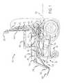
- FIG. 1is a schematic view in elevation of a wheelchair having the tilt and recline features of the invention.
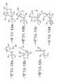
- FIGS. 2 a- 2 dschematically illustrate the unreclining sequence of the invention.
- FIGS. 3 a- 3 dschematically illustrate a different unreclining sequence of the invention.
- FIG. 4is a schematic elevational view of the wheelchair back frame and counterbalanced shear plate.
- FIG. 5is a schematic view in elevation of a tilting and reclining wheelchair according to the invention.
- FIG. 6is a schematic view in elevation of a different tilting and reclining wheelchair according to the invention.
- FIG. 7is a schematic view in elevation of another tilting and reclining wheelchair according to the invention.
- FIG. 8is a schematic view in elevation of yet another tilting and reclining wheelchair according to the invention.
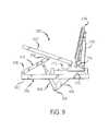
- FIG. 9is a schematic view of a different wheelchair capable of tilting and reclining according to the invention.
- FIGS. 10 a- 10 dschematically illustrate an unrecline sequence of the invention, with a high initial angle of recline.
- FIGS. 11 a- 11 dschematically illustrate an unrecline sequence of the invention, with a moderate initial angle of recline.
- FIGS. 12 a- 12 cschematically illustrate an unrecline sequence of the invention, with a low initial angle of recline.
- FIGS. 13 a- 13 dschematically illustrate various recline positions of the back frame in relation to a threshold angle of recline.
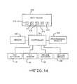
- FIG. 14is a schematic control diagram illustrating apparatus for programming and operating a wheelchair according to an embodiment of the invention.
- FIG. 15illustrates Table I, a sequence of setpoints of ordered pairs of numbers.
- FIG. 16is a graph of the ordered pairs of numbers from Table I in FIG. 15 .
- FIG. 17illustrates a graph of an equation used to control the articulation of an articulated member.
- FIG. 18illustrates a graph of another equation used to control the articulation of a different articulated member.
- a wheelchair indicated generally at 10is comprised of a wheelchair base 12 , which is mounted for movement on front caster wheels 14 and rear drive wheels 16 .
- the wheelchairis preferably provided with a drive motor, not shown, for each of the drive wheels, and a source of power for the drive motors, also not shown.
- a seat frame 18supports a seat cushion 20 for the support of the user.
- a back frame 22is provided to support the user's body, and a head rest 24 supports the user's head.
- the user's armscan be supported by armrests, partially shown at 26 .
- Leg rests 28 and footrests 30are also provided.
- the seat frameis mounted for rotation or tilting in a clockwise direction (as shown in FIG. 1 ) so that the wheelchair user can be tipped back to shift the user's weight for comfort purposes and to relieve pressure from various body parts.
- the seat frame 18is pivotally mounted at tilt pivot points 34 , which are attached to a carriage 36 .
- the carriage 36is mounted for a sliding forward and rearward movement along a track or glide 38 fixed to the wheelchair base 12 . Any other type of sliding movement can be used.
- a seat frame rear cross piece, not shown,can be an integral part of the carriage. As the carriage 36 is moved forward within the glide, the tilt pivot points 34 , and hence the seat frame, are pulled forward with respect to the wheelchair base 12 .
- a tilt actuator 42which can be an electrically powered linear actuator, is connected to the base to pull the carriage 36 forward with respect to the base, thereby tilting the seat frame 18 . As the carriage slides forward, the tilt linkage 40 pushes up the front of the seat frame 18 .
- the seat frameis provided with a tilt sensor 44 that provides an indication of the amount of tilt or rotation of the seat frame with respect to a frame of reference such as the wheelchair base 12 .
- the tilt sensor 44can be any suitable means for measuring the tilt.
- a tilt sensor that can be used for measuring tilt (or recline)is a potentiometer that provides an electrical signal indicative of the amount of tilt of the seat frame.
- pulses generated by a reed switch and magnets associated with the actuatorcan be used to provide an electrical signal indicative of the amount of tilt or recline.
- Another means for measuring tilt or reclineis a quadrature device. As shown, the tilt sensor 44 can be connected via a belt to the tilt pivot so that the potentiometer rotates upon tilting the seat frame.
- the tilting mechanism illustrated in FIG. 1uses a horizontally oriented linear actuator, a vertically oriented linear actuator or any other tilting mechanism could be used as well.
- the leg rests 28are adapted with a leg rest actuators 48 that pivot the leg rests about pivot points 50 with respect to the seat frame 18 .
- the leg restsare optionally provided with leg rest extensions 52 , powered by extension actuators 54 to stretch out the length of the leg rests, thereby changing the distance between the footrests 30 and the seat frame.
- the leg rest extensionsallow the leg rests to conform to the needs of the wheelchair user.
- the footrests 30can be pivotally mounted with respect to the leg rests 28 , in a manner not illustrated, so that the angle between the footrests and the leg rests can be changed to accommodate the needs of the wheelchair user.
- leg rest extensions and the pivoting of the footrestsinvolve the use of movable frame members i.e., the leg rests 28 and the footrests 30 , that can be moved to provide the wheelchair with user conforming characteristics.
- User conforming characteristicsmeans that various frame members are moved to fit the particular physical characteristics of the user throughout various ranges of motion of the movable frame members.
- the frame memberIn conforming the frame member to the user, the frame member is moved or positioned in such a way as to minimize or eliminate the shear stress and other forces on the user's body.
- the raising of the leg rests 28 by the action of the leg rest actuator 48may require a corresponding extension of the leg rest extension 52 by the leg rest extension actuator 54 to accommodate the anatomical needs of the wheelchair user during this particular motion.
- the wheelchair back frame 22is mounted for reclining motion about recline pivot points 58 .
- the recline pivot pointscan be positioned on the seat frame 18 as shown, or can be positioned on the wheelchair base 12 or on the carriage, as will be explained below.
- the reclining movement of the back framecan be driven by any suitable mechanism, such as a recline actuator 60 mounted on the carriage. Operation of the recline actuator rotates or reclines the back frame 22 from an initial position, shown in FIG. 1 , to a reclined position.
- the recline actuator 60is also used to raise up or unrecline the back frame.
- the initial position for the back framecan be any suitable orientation, it is preferably generally vertical, which is roughly 90 degrees with respect to the wheelchair base 12 or with respect to a horizontal line 62 .
- the recline actuator 60When the back frame 22 is in a vertical position, the recline actuator 60 is vertically oriented. Recline sensors 64 , which can be similar to the tilt sensors 44 , can be used to measure the amount of recline of the back frame. The recline sensors could also be mounted in the actuator.
- the back frame 22 of the wheelchairis provided with a shear plate 68 that is mounted for movement with respect to the back frame.
- the shear plate 68can be any suitable back support member, and can be provided with a cushion, not shown.
- a shear plate actuator 70is connected to the shear plate 68 and the back frame to move the shear plate with respect to the back frame. The movement of the shear plate is up and down with respect to the back frame, when the back frame is in a vertical orientation. More precisely the movement of the shear place is toward or away from the recline pivots 58 .
- a shear plate sensor 72measures the amount of movement of the shear plate with respect to the back frame.
- the head rest 24is mounted at the top end of the back frame.
- the head restcan be mounted for movement along length of the back frame (i.e., vertically in the view shown in FIG. 1 ) as well as movement forward or rearward with respect to the back frame.
- the head rest 24can be mounted on the shear plate 68 for movement relative to the back frame 22 .
- the headrestcan be provided with a sensor, not shown, that indicates the position of the headrest with respect to a frame of reference, which can be the back frame 22 , the shear plate 68 , or the wheelchair base 12 .
- a controller 76is provided to control the various wheelchair seating functions and movement of the various movable frame members, i.e., the seat frame 18 , back frame 22 , head rest 24 , arm rests 26 , leg rests 28 , and foot rests 30 .
- the controllercan be any device suitable for controlling the various functions of the wheelchair.
- the controller 76is a computer that is capable of receiving input from the various sensors, storing positioning sequences in a storage device, and sending signals to various actuators for moving the various frame members.
- sensor 44 for sensing the amount of tilt of the seat frame and sensor recline sensor 64 for sensing the amount of recline of the back framecan be linked by a connection to the controller to enable the controller to be aware of the movement of the seat frame and back frame.
- the connectioncan be a hard wire as shown in the drawings, a radio signal device, or any other suitable device for communicating between the sensors and the controller.
- the controllercan be programmed to maintain limits associated with the tilt and recline features of the wheelchair.
- the controllercan be programmed to allow the speed of the tilt and recline actuators to be adjusted.
- the controllercan be provided with a timer or alarm that can be set to alert the user that it is time to perform a weight shift function.
- the shear plate 68can be counterbalanced to make it easier to adjust the relative position of the shear plate and the back frame 22 .
- Thiscan be accomplished by providing a counter weight 80 that is preferably mounted for vertical (parallel) movement along a counterweight guide 82 .
- the counterweight 80can be mounted by a cable 84 that extends around a pulley 86 and is anchored at a cable anchor 88 .
- Shear guides 90can optionally be used to guide the shear plate with respect to the back frame 22 .
- a clutchcan be associated with the pulley 86 , or the any other movable aspect of the shear plate, to selectively allow movement of the shear plate with respect to the back frame.
- the controllercan be programmed so that the clutch allows movement of the shear plate with respect to the back frame only when the back frame is reclining.
- Other control schemescan be used, such as controlling the pulley to selectively allow movement of the shear plate with respect to the back frame.
- the controllercan be programmed so that the movement of the shear plate with respect to the back frame is normally restricted, but is unrestricted when the back frame is reclining.
- the term “restricted”means that the relative movement between the shear plate and the back frame is prevented, and “unrestricted” means that the restriction is lifted.
- a method of programming the individual shear characteristics of each wheelchair user for his or her particular wheelchairThis is accomplished by taking the user through a recline sequence and measuring the shear generated at the shear plate 68 at each point during the reclining process. This can be done in finite increments or as a continuum.
- the shearis measured at several angles of recline, which means at least four different angles, preferably at least eight angles, and up to as much as an infinite amount of angles in a continuum. Set points or data points that include such information as position and shear measurements are taken during this programming process.
- the controller 94will adjust the shear plate during the recline sequence to avoid generating shear between the user and the shear plate 68 .
- Operation of the programmed controller 94includes driving the shear plate 68 as the back frame 22 reclines to eliminate any displacement between user and the shear plate.
- the controllersenses the recline angle through the recline sensor 64 and moves the shear plate to a programmed location.
- the controller 94can determine the position of the shear plate through the shear sensor.
- the shear functionthat is the position of the shear plate as a function of the recline angle, is unique for each individual user. Furthermore the shape of this function is unique as well. For this reason attempting to set this program with a mechanical linkage and in a linear relationship, as most current systems do, results in a less than satisfactory control pattern.
- the programming of the controller according to the method of the inventioncan be accomplished in a variety of ways.
- One of the methods used to reduce shearis to counter balance the shear plate 68 , as disclosed above in FIG. 4 .
- the shear plateis mounted on the glides 90 to allow it to easily move up and down on the back frame 22 .
- the back frameis pivotally connected for a reclining motion.
- the counterweight 80is mounted to a second glide 82 positioned between it and the back frame 22 .
- This counterweight glide 82is mounted such that the weight 80 may also travel up and down parallel to the shear plate.
- the mass of the counter weight 80is the same as the shear plate 68 . With this configuration any shear force present as a result of reclining an individual seated in the chair will cause the shear plate to move and mitigate this force.
- both the shear plate 68 and the counter weight 80transfer more and more of their weight to the glides 82 and 90 , thereby maintaining the initial equilibrium.
- the backis counter-balanced using a weight equivalent to the weight of the shear plate 68 and everything attached to it, such as a back cushion, not shown, the head rest 24 , and other equipment associated with the back frame.
- a first method of establishing tilt and recline control parameters for a particular userinvolves sensing the shear forces experienced by the user during a recline operation. As the user reclines, any shear forces that exist will cause the back to travel up or down, thereby mitigating the shear force. The controller will record the readings of the shear plate at intervals during the recline and, using these points, generate a shear function.
- a second method of establishing tilt and recline control parameters for a particular useris to recline the back frame 22 and at intervals stop and adjust the shear plate 68 .
- the adjustmentsare recorded.
- the controller 94is used to stop the recline process at predetermined intervals. The user, a therapist or an attendant can make the adjustments.
- a third method of establishing the tilt and recline control parameters for a particular useris to use some point on the user's body to follow during the recline programming.
- This reference pointis preferably a reference with respect to the user's head since the head is attached through the spine to the hip, and therefore makes a fairly reliable frame of reference.
- the movements of the seat frame 18 and the back frame 22are independently actuated, but are coordinated for the best kinematic motion for the wheelchair user.
- both the tilt actuator 42 for the seat frame 18 and the recline actuator 60 for the back frameare used.
- the seat framemust rotate, and at the same time the recline actuator 60 must rotate the back frame to maintain the seat-to-back angle at a constant level.
- the recline actuator 60does not move the back frame 22 in relation to the seat frame 18 , but rather in relation to the wheelchair base 12 or the carriage 36 .
- the controller 94 of the inventionis also capable of activating the tilt and recline in concert.
- the unrecline processi.e., the process of returning to an upright position from a reclined position
- the unrecline processcan be accomplished in a manner to overcome the tendency of the user to slide out of the seat In during the unrecline process. It has been discovered that during the unrecline process, if the user tilts the seat frame 18 upward before the back fame is unreclined or brought up, the user's hips are stabilized and the unrecline process is more stable for the user, and more repeatable.
- the controller 94can coordinate both the tilt and the recline operations into a single function. Several sequences exist.
- FIGS. 2 a- 2 dA first unrecline sequence according to this invention is shown in FIGS. 2 a- 2 d .
- the wheelchairis initially configured with the seat frame 18 untilted with respect to the wheelchair base 12 , and with the back frame 22 reclined to an angle generally parallel to the horizontal line 62 .
- the angle formed between the seat frame and the back frame, indicated at 106is approximately 180 degrees.
- the unrecline processbegins by tilting the seat frame 18 a moderate amount, such as an angle 108 of about 30-45 degrees with respect to the horizontal line 62 , for example. This is shown in FIG. 2 b .
- the third stepis an unreclining of the back frame 22 so that the angle 106 between the seat frame and the back frame is within the range of from about 80 to about 120 degrees, such as about 90 degrees, for example.
- the final stepis bringing both the seat frame and the back frame to an upright position together as the seat-to-back angle 106 is maintained relatively constant, as shown in FIG. 2 d .
- FIGS. 3 a- 3 dAn alternate unrecline sequence is shown in FIGS. 3 a- 3 d .
- This sequenceis similar to that shown in FIGS. 2 a- 2 d , except that instead of tilting the seat frame 18 (shown in FIG. 2 b ) prior to beginning the unrecline of the back frame 22 (shown in FIG. 2 c ), the unrecline of the back frame 22 occurs simultaneously with the tilt of the seat frame 18 , as shown in FIG. 3 b .
- the angle 106 between the seat frame and the back frameis brought to within the range of from about 80 to about 120 degrees, as shown in FIG. 3 c , the seat frame and back frame are both rotated to the upright position, as shown in FIG. 3 d , while maintaining the angle 106 within the range of from about 80 to about 120 degrees.
- the wheelchairindicated generally at 110 includes a base 112 , and a carriage 114 slidably mounted on a guide member 116 for forward and rearward movement by the action of a linear actuator 118 .
- the seat frame 120is pivotally mounted on the carriage 114 at pivot point 122 , and linked to the base 112 with a pivotally mounted strut 124 so that when the carriage is moved forward the seat frame 120 will tilt or rotate.
- the carriage 114 , strut 124 and actuator 118comprise a seat frame tilting mechanism for tilting or rotating the seat frame 120 .
- the back frame 126is pivotally mounted on the seat frame at pivot point 128 , which can be the same as the seat frame pivot point 122 , although not shown that way in FIG. 5.
- a rigid structural member, such as bell crank 130is connected via pivot point 132 and actuator 134 to the seat frame 120 .
- the bell crank and actuator 134act together to form a back frame recline mechanism for rotating the back frame 126 with respect to the seat frame.
- the actuator 134is pivotally connected to the seat frame 120 at pivot point 136 . It can be seen that with no activation of the actuator 134 , tilting of the seat frame 120 causes a corresponding movement of the back frame, and the angle between the seat frame and the back frame is maintained constant. Movement or activation of the actuator 134 causes the back frame to move relative to the seat frame, thereby changing the angle between the seat frame and the back frame. It is to be understood that numerous other arrangements can be used to move the back frame relative to the seat frame.
- the back frame 126is pivotally mounted at pivot point 128 relative to the carriage 114 , and hence relative to the base 112 , rather than relative to the seat frame 120 .
- the back frame 126is still actuated with respect to the seat frame 120 by means of the actuator 134 and the bell crank 130 , so that movement of the seat frame 120 will cause a similar movement of the back frame 126 .
- Thiswill keep the angle between the seat frame and the seat back relatively constant when the seat frame 120 is tilted, unless the actuator 134 changes that angle.
- the wheelchair 110 illustrated in FIG. 7includes the seat frame 120 pivotally mounted from the carriage 114 at pivot point 122 , and the back frame 126 pivotally mounted from the seat frame at pivot point 128 .
- the back frame 126is movable with respect to the carriage 114 by means of a back frame actuator 138 , pivotally mounted from the carriage at pivot point 140 .
- the back frame actuator 138is pivotally connected to the back frame 126 at pivotal connection 142 . It can be seen that tilting the seat frame 120 will cause some [a significant] movement in the back frame 126 relative to the seat frame, but this movement will not be significant.
- the back frameis independently operable relative to the tilting of the seat frame. In order to tilt the seat frame and still maintain a constant angle between the seat frame and the back frame, both the seat frame actuator 134 and the back frame actuator 138 must be coordinated.
- FIG. 8illustrates another embodiment of the wheelchair 110 similar to those shown in FIGS. 5-7 , but having both the back frame pivot point 128 and the back frame actuator 138 mounted on the carriage 114 . It can be seen that tilting of the seat frame 120 will not result in any movement of the back frame 126 .
- the back frameis independently operable relative to the tilting of the seat frame. In order to tilt the seat frame and still maintain a constant angle between the seat frame and the back frame, both the seat frame actuator 134 and the back frame actuator 138 must be coordinated.
- the seat frame 150 of another wheelchair 152is mounted on a strut 154 for elevation with respect to the base 156 .
- the strut 154is pivotally mounted at a first end 158 on a forward end 160 of the base and pivotally connected at a second end 162 to the seat frame 150 .
- An actuator 164is pivotally connected (indirectly) to the base 156 via a support arm 166 , at pivot point 168 .
- the actuatoris also pivotally connected to the strut.
- the strut 154tilts or rotates the seat frame 150 .
- the back frame 174is mounted via pivot pin 176 to the carriage 170 and is articulated or reclined by the action of the back frame actuator 178 .
- the wheelchaircan be programmed so that the unrecline sequence includes a certain amount of upward tilt of the seat frame 18 at the beginning of the unrecline process.
- This initial upward tilting of the seat frame 18is referred to as pretilt.
- the amount pretiltis programmed into the wheelchair controller 76 to be a function of the initial angle of recline at the initiation of the recline sequence.
- the controller 76is preprogrammed with a plurality of sequences for moving the seat frame 18 and the back frame 22 during an unrecline procedure.
- the sequencesinclude tilting the seat frame 18 as an initial part of the unrecline sequence.
- the sequencesinvolve pretilting the seat frame 18 an amount that is a function of the initial angle of recline at the initiation of a recline sequence.
- the back frame 22is at a great or high angle of recline 200 . (It is to be understood that the actual amount of recline of the back frame is the complimentary angle to angle 200 .)
- the seat frame 18is tilted upward first, as shown in FIG. 10 b , to a tilt angle 202 .
- FIGS. 10 c and 10 dThe various positions of the back frame 22 and seat frame 18 in FIGS. 10 a- 10 d represent a sequence for the unrecline function.
- FIGS. 11 a- 11 dshow an unrecline sequence where the initial angle of recline 200 is somewhat less than the initial recline angle shown in FIG. 10 a .
- the unrecline sequence shown in FIGS. 11 a- 11 ddiffers from the sequence shown in FIGS. 10 a- 10 d in that the pretilt angle 202 shown in FIG. 11 b is not as great as that required in the sequence shown in FIGS. 10 a- 10 d.
- FIGS. 112 a- 12 cshow an unrecline sequence where the initial angle of recline 200 is even less than that shown in FIG. 11 a .
- the pretilt angle 202 shown in FIG. 12 bis accordingly even less than that shown in FIG. 11 b.
- the sequence of movement of the back frame 22 and the seat frame 18can be programmed into the controller 76 so that the sequence can be repeated upon command. It is to be understood that other movable elements of the wheelchair, such as the head rest 24 , armrests 26 , leg rests 28 and footrests 30 can also be controlled as part of a programmed sequence of operation, similar to the unrecline sequence shown in FIGS. 10 a- 10 d . It can be seen from FIGS. 10 a- 10 d , 11 a- 11 d and 12 a- 12 c that the back frame is unreclined according to one of the preprogrammed sequences in response to the determined initial angle of recline.
- the preprogrammed sequencesprovide that greater initial angles of recline involve greater amounts of tilt of the seat frame during the unrecline procedure than the amounts of tilt provided for in the preprogrammed sequences for lesser initial angles of recline.
- the wheelchaircan be provided with a programming module 204 that can be connected to the controller 76 , either permanently or temporarily for the purpose of programming the controller and entering sequences for movement of various movable members of the wheelchair.
- the wheelchair controller 76is programmable to establish a memory or bookmark for an initial position of the movable elements of the wheelchair so that the wheelchair elements can be returned to the initial position after being moved away from that initial position.
- This functionis referred to as a bookmark.
- This bookmark functioncan be used in conjunction with a wheelchair having a recline function, as well as with other functions.
- the wheelchairincludes a back frame 22 , a recline actuator 60 for reclining the back frame 22 , the recline sensor 64 , for determining the angle of recline, and the controller 76 for controlling the recline actuator 60 .
- the controllerhas a memory device 206 , as indicated in FIG. 14 .
- the first stepis to determine an initial angle of recline of the wheelchair with the recline sensor 64 , and then to store data corresponding to the determined initial angle of recline in the memory device 206 .
- the movable membersi.e., the back frame 22 and the seat frame 18
- the controllercan access the stored data corresponding to the initial angle of recline and then return the back frame to the initial angle of recline by controlling the recline actuator in response to the stored data.
- the wheelchaircan be provided with an input device 208 , shown in FIG. 14 , that is connected to the controller 76 for communicating with the controller 76 .
- the input device 208can be provided with a switch 210 capable of signaling the controller 76 to return the back frame 22 to the initial angle of recline.
- This bookmark functioncan also be used for controlling the angle of tilt by determining an initial angle of tilt of the seat frame 18 with the tilt sensor 44 , and storing data corresponding to the determined initial angle of tilt in the memory device. After the seat frame 18 is moved to a different portion resulting in a change in the angle of tilt 202 , the seat frame 18 can be returned to the initial angle of tilt by controlling the tilt actuator in response to the stored data corresponding to the initial angle of tilt.
- the book mark functioncan be used to select a plurality of preferred positions for any of the movable members of the wheelchair.
- the method of this embodimentinvolves selecting a plurality of angles of recline of the back frame 22 , and storing data corresponding to the selected angles of recline in the memory device 206 .
- the input device 208is provided with a plurality of switches 210 - 214 that are operatively connected to the controller 76 .
- the controlleris programmed to associate each of the selected angles of recline with one of the switches 210 - 214 so that activating each switch causes the controller to access the stored data and return the back frame 22 to the selected angle of recline associated with the switch.
- This methodcan also be applied to the movement of the seat frame.
- the methodinvolves sensing an angle of tilt of the seat frame 18 corresponding with each of the plurality of selected of angles of recline of the back frame 22 , and storing data corresponding to the sensed angles of tilt in the memory device 206 , wherein the stored data includes a link between each selected angle of recline and its corresponding angle of tilt.
- the controlleris programmed so that activating each switch 210 - 214 not only returns the back frame to the selected angle of recline associated with the switch, but also returns the seat frame to the angle of tilt linked to the corresponding angle of recline.
- this methodapplies to any movable member of the wheelchair, including such movable members as the head rest 24 , armrests 26 , leg rests 28 and footrests 30 .
- the movable memberscan be programmed to move to positions that are particularly advantageous for different situations.
- the movable memberscan be programmed to take up a certain position when the wheelchair is to be moved into a vehicle for transport.
- a different position for various movable wheelchair memberscould be provided for when the wheelchair is to be driven up or down a hill or an incline.
- the wheelchairis provided with a preprogrammed sequence or plurality of sequences of moving various movable wheelchair members, such as for example, the recline and unrecline of the wheelchair back frame 22 .
- the controller 76can be preprogrammed with one or more unrecline sequences for moving the seat frame 18 and the back frame 22 during an unrecline procedure, where the unrecline sequence includes the pretilt function of tilting the seat frame as an initial part of the unrecline sequence.
- the controlleris programmed with a threshold angle of recline, indicated at 216 in FIG. 13 .
- the controllerwill respond to a command to unrecline the back frame 22 in one of two ways, depending on whether or not the initial angle of recline exceeds the threshold angle.
- the unrecline procedurefollows the preprogrammed unrecline sequence, which typically would include the pretilt function. However, if the initial angle of recline is below the threshold angle 216 , as illustrated in FIGS. 13 a , 13 b and 13 c , then the unrecline procedure involves unreclining the back frame without tilting the seat frame. Therefore, when a command to unrecline is given to the controller 76 , there is first a determination as to the initial angle of reline 200 . A comparison of the initial angle of recline with the threshold angle is made.
- the unrecline processis carried out according to the preprogrammed sequences, and if the initial angle is not above the threshold angle, the recline is carried out in a straightforward manner. It can be seen that the unreclining of the back frame is controlled in response to the comparison of the initiation angle with the threshold angle.
- the controlleris provided with a capability for modifying the threshold angle. This could be accomplished using the programming module 204 or the input device 208 .
- the wheelchairis configured with a first articulated member, such as the back frame 22 , that is mounted for articulation, i.e., recline and unrecline, within a first range of back frame recline positions, such as the entire range of motion for the back frame 22 .
- This first articulated memberi.e., the back frame 22
- the wheelchairis configured with a second articulated member, such as the seat frame 18 , that is mounted for articulation within a second range of seat frame positions, i.e., the entire range of tilt motion of the seat frame 18 .
- This second articulated memberi.e., the seat frame 18
- the controller 76is connected to the first and second actuators, i.e., actuators 60 and 42 , for articulating the back frame and seat frame, respectively, in a coordinated fashion.
- the controller 76is programmed with a sequence of setpoints of ordered pairs of numbers, one of the numbers of the ordered pairs being indicative of the position of the first back frame 22 along the first range, and the other of the numbers of the ordered pairs being indicative of the position of the second articulated member along the second range. See, for example the sequence of setpoints in FIG. 15 , which includes Table I—Sequence of Setpoints, and FIG. 16 , which is a graph of the ordered pairs of numbers from Table I in FIG. 15 .
- Each set pointrepresents an ordered pair of position for the articulation of the seat back 22 and the seat frame 18 along their respective ranges of motion.
- the input device 208 associated with the controller 76can provide input from a wheelchair user to the controller.
- the controller 76is programmed to provide signals, in response to signals from the input device 208 , to the back frame actuator 60 and the seat frame actuator 42 , with the signals directing articulation of the back frame 22 and the seat frame 18 , respectively, along the setpoints.
- Other input devices besides input device 208such as a programming pendant, not shown, can be used to program the controller or to modify the information in the controller.
- the setpoints of the sequencecan be modified by input from the input device 208 .
- the setpoints of the sequencecan be modified by input from sensors for sensing any one of several general parameters relevant to the wheelchair and its environment. Examples of these parameters include the wheelchair velocity, the acceleration of the wheelchair, and the angle of incline of a supporting surface for the wheelchair.
- any of the articulated members of the wheelchaircan be controlled by the controller according to this aspect of the invention.
- Examples beyond the back frame 22 and seat frame 18 already disclosedinclude the legrest 28 , foot rest 30 , arm rest 26 , head rest 24 and shear plate 60 .
- the controlleris programmed with at least one additional sequence of setpoints of ordered pairs of numbers associated with coordinated articulation of one of these additional articulated members, such as the legrest 28 , with the at least one additional sequence coordinating the articulation of the additional articulated member (legrest) with either the first or the second articulated member (back frame 22 or seat frame 18 ).
- the sequence of setpoints programmed into the controller 76can be viewed as a primary sequence, and the controller 76 can programmed with at least one additional sequence of setpoints of ordered pairs of numbers, with the additional sequence being an associated with coordinated articulation of the first and second articulated members using different setpoints from those of the primary sequence, and wherein the controller is configured to switch from the primary sequence to the additional sequence based on input from the input device 208 .
- the controllercan be configured to switch from the primary sequence to the additional sequence based on input from sensors for sensing any one of a number of parameters, such as the wheelchair velocity, the acceleration of the wheelchair (forward, rearward or turning), and the angle of incline of a supporting surface for the wheelchair.
- the controlleris programmed with a first equation that controls the movement of the first articulated member along the first range as a function of time.
- the controlleris programmed to provide signals, in response to signals from the input device 208 , to the first and second actuators, with the signals directing articulation of the first and second members along the first and second ranges, respectively, and according to the first and second equations, respectively.
- the controlleris programmed to direct the first and second actuators to move the first and second members, respectively, in a continuous motion along the first and second ranges, respectively.
- the first and second equationscan be modified by input from the input device.
- the controllercan programmed with at least one additional equation, not shown, associated with coordinated articulation of an additional articulated member, such as the leg rest 28 .
- the at least one additional equationis used by the controller to coordinate the articulation of the additional articulated member and either the first or the second articulated member.
Landscapes
- Health & Medical Sciences (AREA)
- Life Sciences & Earth Sciences (AREA)
- Animal Behavior & Ethology (AREA)
- General Health & Medical Sciences (AREA)
- Public Health (AREA)
- Veterinary Medicine (AREA)
- Chairs For Special Purposes, Such As Reclining Chairs (AREA)
Abstract
Description
Claims (21)
Priority Applications (3)
| Application Number | Priority Date | Filing Date | Title |
|---|---|---|---|
| US10/616,465US6976699B2 (en) | 2000-05-31 | 2003-07-08 | Coordinated articulation of wheelchair members |
| EP04756871AEP1648758A1 (en) | 2003-07-08 | 2004-07-08 | Coordinated articulation of wheelchair members |
| PCT/US2004/022191WO2005007498A1 (en) | 2003-07-08 | 2004-07-08 | Coordinated articulation of wheelchair members |
Applications Claiming Priority (3)
| Application Number | Priority Date | Filing Date | Title |
|---|---|---|---|
| US09/583,854US6588792B1 (en) | 2000-05-31 | 2000-05-31 | Method of programming and operating tilt and recline functions in a wheelchair |
| US10/040,279US6715784B2 (en) | 2000-05-31 | 2001-10-19 | Method programming and operating a wheelchair having tilt and recline functions |
| US10/616,465US6976699B2 (en) | 2000-05-31 | 2003-07-08 | Coordinated articulation of wheelchair members |
Related Parent Applications (1)
| Application Number | Title | Priority Date | Filing Date |
|---|---|---|---|
| US10/040,279Continuation-In-PartUS6715784B2 (en) | 2000-05-31 | 2001-10-19 | Method programming and operating a wheelchair having tilt and recline functions |
Publications (2)
| Publication Number | Publication Date |
|---|---|
| US20040094936A1 US20040094936A1 (en) | 2004-05-20 |
| US6976699B2true US6976699B2 (en) | 2005-12-20 |
Family
ID=34079661
Family Applications (1)
| Application Number | Title | Priority Date | Filing Date |
|---|---|---|---|
| US10/616,465Expired - LifetimeUS6976699B2 (en) | 2000-05-31 | 2003-07-08 | Coordinated articulation of wheelchair members |
Country Status (3)
| Country | Link |
|---|---|
| US (1) | US6976699B2 (en) |
| EP (1) | EP1648758A1 (en) |
| WO (1) | WO2005007498A1 (en) |
Cited By (33)
| Publication number | Priority date | Publication date | Assignee | Title |
|---|---|---|---|---|
| US20040015320A1 (en)* | 2002-03-18 | 2004-01-22 | Hiroshi Nagaoka | Bottom adjusting action control system for a bed or the like |
| US20040010850A1 (en)* | 2002-03-18 | 2004-01-22 | Hiroshi Nagaoka | Coordinative lifting control method of bottom sections for lying furniture such as a bed |
| US20050273933A1 (en)* | 2002-03-18 | 2005-12-15 | Hiroshi Nagaoka | Coordinative control method for the back and knee bottom sections of a bed or the like |
| US20060290184A1 (en)* | 2005-06-16 | 2006-12-28 | Stoneman William C | Medical patient support chair |
| US20070050096A1 (en)* | 2005-08-31 | 2007-03-01 | Invacare Corporation | Programmable actuator controller for power positioning seat or leg support of a wheelchair |
| US20070055424A1 (en)* | 2005-08-31 | 2007-03-08 | Darryl Peters | Method and apparatus for setting or modifying programmable parameter in power driven wheelchair |
| US20070074917A1 (en)* | 2005-08-31 | 2007-04-05 | Invacare Corp. | Adjustable mount for controller of power driven wheelchair |
| US20070296182A1 (en)* | 2006-05-10 | 2007-12-27 | Graco Children's Products Inc. | Foldable and height-adjustable stroller |
| US20080030053A1 (en)* | 2006-08-01 | 2008-02-07 | Sanyo Electric Co., Ltd. | Massage machine of chair type |
| US20080157501A1 (en)* | 2004-10-29 | 2008-07-03 | Flemming Moller | Comfort Wheelchair |
| US20090045599A1 (en)* | 2007-08-14 | 2009-02-19 | Nancy Balcom | Reconfigurable tilt wheelchair |
| US20090079159A1 (en)* | 2007-09-21 | 2009-03-26 | Michael Every | Foldable wheelchair |
| US20090151074A1 (en)* | 2002-03-18 | 2009-06-18 | Paramount Bed Co., Ltd. | Coordinative Control Method For Adjusting The Back and Knee Bottom Sections Of An Adjustable Bed, And Computer Program For Implementing Same |
| US20110000744A1 (en)* | 2007-05-18 | 2011-01-06 | Leonard Smith | Stairlifts |
| US20110227380A1 (en)* | 2007-08-10 | 2011-09-22 | Oliver Buntz | Seat occupancy detection unit |
| US8596719B2 (en) | 2010-10-01 | 2013-12-03 | Permobil Ab | Wheelchair backrest assembly |
| US20130328365A1 (en)* | 2012-06-12 | 2013-12-12 | Chadwick W. HANNAH | Adjustable spine pressure relief apparatus |
| US20140367944A1 (en)* | 2013-06-18 | 2014-12-18 | Michael Nyitray | Adjustable wheelchair seat |
| US9056036B2 (en) | 2012-10-12 | 2015-06-16 | Michael Nyitray | Multipurpose vehicle |
| US9073399B1 (en)* | 2014-10-10 | 2015-07-07 | Max Mobility, Llc | System and method for adjusting a wheelchair seat |
| US20170035633A1 (en)* | 2015-08-07 | 2017-02-09 | CareChair | Automated variable bed to wheelchair system |
| US9596936B2 (en)* | 2012-06-19 | 2017-03-21 | Sitight, Inc. | Seating device |
| US9682603B2 (en) | 2014-10-10 | 2017-06-20 | Max Mobility, Llc | System and method for adjusting a wheelchair seat |
| US9907713B2 (en)* | 2012-11-06 | 2018-03-06 | Invacare International Sarl | Wheelchair including a tiltable seat |
| US9999557B2 (en)* | 2016-07-14 | 2018-06-19 | Challenging Solutions, Inc. | Robotic mobility device |
| US10052248B1 (en)* | 2015-09-04 | 2018-08-21 | University Of South Florida | Wireless adjustable wheelchair headrest |
| US10085906B2 (en)* | 2016-06-21 | 2018-10-02 | Hefei University Of Technology | Medical apparatus for standing aid |
| US10327554B2 (en) | 2016-02-10 | 2019-06-25 | The Comfort Companies, Llc | Adjustable head support |
| US10716721B2 (en) | 2017-08-11 | 2020-07-21 | The Comfort Companies, Llc | Hinge assembly for a wheelchair component |
| US10772774B2 (en) | 2016-08-10 | 2020-09-15 | Max Mobility, Llc | Self-balancing wheelchair |
| US10829222B2 (en)* | 2017-11-20 | 2020-11-10 | B/E Aerospace, Inc. | Aircraft passenger seat with zero-g taxi, take-off and landing recline position |
| US11035443B2 (en)* | 2018-09-19 | 2021-06-15 | Zhejiang Linix Motor Co., Ltd. | Footrest lifting and angle adjusting mechanism of electrically powered wheelchair |
| US11957631B2 (en) | 2022-07-13 | 2024-04-16 | Invacare Corporation | Wheelchair and suspension systems |
Families Citing this family (18)
| Publication number | Priority date | Publication date | Assignee | Title |
|---|---|---|---|---|
| US7094188B2 (en)* | 2002-05-17 | 2006-08-22 | Reitz Alan S | Low-resistance exercise and rehabilitation chair |
| GB2425187B (en)* | 2005-04-15 | 2010-09-22 | P G Drives Technology Ltd | Electronic control system |
| WO2007027846A2 (en)* | 2005-08-31 | 2007-03-08 | Invacare Corporation | Method and apparatus for automated positioning of user support surfaces in power driven wheelchair |
| EP2213562A3 (en)* | 2005-12-28 | 2011-07-06 | Equos Research Co., Ltd. | Motor vehicle |
| DE102006011710B3 (en)* | 2006-03-14 | 2007-08-02 | Meyra Wilhelm Meyer Gmbh & Co. Kg | Wheel-chair for heavy patients with limited motor activity, has back-support movably mounted on slide |
| SE532937C2 (en)* | 2006-09-19 | 2010-05-11 | Permobil Ab | Control system for a wheelchair |
| DE602007009259D1 (en) | 2007-07-19 | 2010-10-28 | Fundacion Tekniker | WHEELCHAIR |
| EP2186497B1 (en) | 2008-11-17 | 2013-05-08 | Hill-Rom Services, Inc. | Anthropometrically governed occupant support |
| CA2757710A1 (en)* | 2010-11-15 | 2012-05-15 | Pride Mobility Products Corporation | Tiered operation option scanning for wheelchairs |
| JP2015167010A (en)* | 2014-02-17 | 2015-09-24 | パナソニックIpマネジメント株式会社 | Display terminal and display terminal system including the same |
| EP2946758B1 (en) | 2014-05-19 | 2017-02-01 | Sunrise Medical GmbH & Co. KG | Backrest assembly for wheelchair with reclining seat |
| KR101661346B1 (en)* | 2015-07-22 | 2016-10-04 | (주)코젤 | the structure for back plate sliding of a medical chair |
| CN106923979B (en)* | 2017-04-11 | 2018-10-23 | 武汉理工大学 | A kind of intelligent controlling device and method of the adjustable wheelchair of structure |
| US11607355B2 (en)* | 2017-10-12 | 2023-03-21 | Sunrise Medical (Us) Llc | Wheelchair having an adjustable base |
| CN109009713A (en)* | 2018-05-02 | 2018-12-18 | 绍兴文理学院元培学院 | A kind of autobalance multifunctional wheelchair |
| US11712382B2 (en) | 2019-10-01 | 2023-08-01 | Christiana Care Health System, Inc. | Wheelchair with dynamic occupant-tilt feature |
| KR20210060138A (en)* | 2019-11-18 | 2021-05-26 | 엘지전자 주식회사 | Robot |
| CN112515873B (en)* | 2020-11-26 | 2023-05-09 | 佛山市东方医疗设备厂有限公司 | Wheelchair capable of being adjusted in real time based on human body state |
Citations (49)
| Publication number | Priority date | Publication date | Assignee | Title |
|---|---|---|---|---|
| US2849051A (en)* | 1956-12-05 | 1958-08-26 | Ill George W Streeter | Convertible wheeled chair |
| US3059970A (en) | 1960-02-01 | 1962-10-23 | White S Dental Mfg Co | Chairs having tilting backs |
| US3147038A (en) | 1964-09-01 | figure | ||
| US3191990A (en) | 1962-05-31 | 1965-06-29 | Rugg Donald Edwin | Reclining mechanism for wheelchairs and the like |
| US3222105A (en) | 1964-01-23 | 1965-12-07 | James W Cross | Dental chair with consoles |
| US3597554A (en) | 1969-08-14 | 1971-08-03 | Peter C Granata Jr | Memory and control device |
| US4054319A (en) | 1975-10-23 | 1977-10-18 | The United States Of America As Represented By The Secretary Of The Navy | Stand-aid invalid wheelchair |
| US4204255A (en) | 1976-09-09 | 1980-05-20 | Keiper Automobiltechnik Gmbh & Co Kg | Apparatus for adjusting a vehicle seat |
| US4306124A (en) | 1978-10-09 | 1981-12-15 | Nissan Motor Co., Ltd. | Position memory device |
| US4333681A (en) | 1979-11-16 | 1982-06-08 | Nelson M Eugene | Power operated reclining wheelchair |
| US4434468A (en) | 1979-10-12 | 1984-02-28 | International Telephone And Telegraph Corporation | Automatic position control for a vehicle seat |
| US4451887A (en) | 1980-06-13 | 1984-05-29 | Aisin Seiki Kabushiki Kaisha | System for controlling a door and driver's seat of vehicle |
| US4477874A (en) | 1980-11-25 | 1984-10-16 | Nippondenso Co., Ltd. | Card-operated control system for vehicle components |
| US4510426A (en) | 1982-07-30 | 1985-04-09 | Lectron Products, Inc. | Memory power seat controller |
| GB2158350A (en) | 1984-03-16 | 1985-11-13 | Algonquin Mercantile Corp | Reclinable chair |
| US4616874A (en) | 1983-06-01 | 1986-10-14 | Gebr. Isringhausen | Vehicle seat assembly |
| US4732423A (en) | 1986-10-27 | 1988-03-22 | Bio-Architectural Design, Inc. | Invalid's chair construction |
| US4794999A (en)* | 1985-06-25 | 1989-01-03 | Robert Hester | Wheelchair and method of operating same |
| US4811226A (en) | 1980-09-30 | 1989-03-07 | Toyota Jidosha Kogyo Kabushiki Kaisha | Optimum angle adjusting apparatus for vehicle equipments |
| US4845620A (en) | 1987-12-22 | 1989-07-04 | United Technologies Automotive, Inc. | Control arrangement for vehicle memory seat |
| US4853687A (en) | 1986-12-24 | 1989-08-01 | Ikeda Bussan Co., Ltd. | Programmable adjusting seat control apparatus |
| US4887017A (en) | 1986-10-14 | 1989-12-12 | Aisin Seiki Kabushiki Kaisha | Seat angle regulating apparatus |
| US4920338A (en) | 1987-06-04 | 1990-04-24 | Nissan Motor Co., Ltd. | Automatic seat positioning device for automotive vehicle and the like |
| US5044647A (en) | 1989-11-17 | 1991-09-03 | Folio Products, Inc. | Stabilized reclining wheelchair seat |
| CA2029917A1 (en) | 1990-11-14 | 1992-05-15 | Richard Eakins | Adjustable chair |
| US5123495A (en)* | 1988-06-10 | 1992-06-23 | Quest Technologies, Inc. | Wheelchair stair climbing control system |
| US5181762A (en) | 1990-05-02 | 1993-01-26 | Revab B.V. | Biomechanical body support with tilting leg rest tilting seat and tilting and lowering backrest |
| US5187665A (en) | 1989-10-16 | 1993-02-16 | Nissan Motor Co., Ltd. | Vehicle equipment position control system and the method therefor |
| US5248007A (en)* | 1989-11-21 | 1993-09-28 | Quest Technologies, Inc. | Electronic control system for stair climbing vehicle |
| US5267778A (en) | 1990-03-29 | 1993-12-07 | A-Dec, Inc. | Position control for a dental chair |
| US5292144A (en) | 1992-11-05 | 1994-03-08 | Biomedical Horizons, Inc. | Wheelchair tilting seat conversion kit |
| US5294141A (en) | 1990-11-14 | 1994-03-15 | Invacare Corporation | Attended to self propelled convertible pivoting wheelchair |
| US5297021A (en) | 1992-11-16 | 1994-03-22 | Koerlin James M | Zero shear recliner/tilt wheelchair seat |
| US5366036A (en) | 1993-01-21 | 1994-11-22 | Perry Dale E | Power stand-up and reclining wheelchair |
| US5525901A (en) | 1993-02-02 | 1996-06-11 | Beaudreau Electric, Inc. | Sensor systems for monitoring and measuring angular position in two or three axes |
| US5642302A (en) | 1995-02-21 | 1997-06-24 | Banque De Developpement Du Canada | Method and apparatus for positioning a human body |
| US5712625A (en) | 1995-05-15 | 1998-01-27 | Delco Electronics Corporation | Vehicle operator verification system that prevents vehicle adapting systems from adapting |
| US5751129A (en) | 1996-10-04 | 1998-05-12 | Invotronics Manufacturing | Memory seat module having integrated sensors |
| US5903122A (en) | 1996-02-21 | 1999-05-11 | Bertrand Faure Equipements Sa | Electric command device for controlling seat positioning and storing desired seat positions |
| US5971482A (en) | 1997-10-02 | 1999-10-26 | Invacare Corporation | Constant center of gravity tiltable chair of a wheelchair |
| US6003891A (en) | 1996-11-12 | 1999-12-21 | Invacare Corporation | Tilt wheelchair with center of gravity compensation |
| US6003624A (en) | 1995-06-06 | 1999-12-21 | University Of Washington | Stabilizing wheeled passenger carrier capable of traversing stairs |
| US6015189A (en) | 1991-11-05 | 2000-01-18 | Genus Medical Inc. | Adjustable chair |
| US6068280A (en) | 1996-09-13 | 2000-05-30 | Torres; Hank G. | Self-leveling seat for a wheelchair |
| US6154690A (en) | 1999-10-08 | 2000-11-28 | Coleman; Raquel | Multi-feature automated wheelchair |
| US6158810A (en) | 1998-11-17 | 2000-12-12 | Galloway; Robert | Chair back tilt apparatus |
| US6195603B1 (en) | 1995-08-11 | 2001-02-27 | Lear Corporation | Multiple speed vehicle seat memory control apparatus |
| US6206393B1 (en)* | 1998-11-09 | 2001-03-27 | Invacare Corporation | Constant center of gravity tilt seat of a wheelchair |
| US6276704B1 (en) | 1997-09-23 | 2001-08-21 | Charles J. Suiter | Adjustable wheelchair having a tilting and reclining seat |
- 2003
- 2003-07-08USUS10/616,465patent/US6976699B2/ennot_activeExpired - Lifetime
- 2004
- 2004-07-08WOPCT/US2004/022191patent/WO2005007498A1/enactiveApplication Filing
- 2004-07-08EPEP04756871Apatent/EP1648758A1/ennot_activeWithdrawn
Patent Citations (51)
| Publication number | Priority date | Publication date | Assignee | Title |
|---|---|---|---|---|
| US3147038A (en) | 1964-09-01 | figure | ||
| US2849051A (en)* | 1956-12-05 | 1958-08-26 | Ill George W Streeter | Convertible wheeled chair |
| US3059970A (en) | 1960-02-01 | 1962-10-23 | White S Dental Mfg Co | Chairs having tilting backs |
| US3191990A (en) | 1962-05-31 | 1965-06-29 | Rugg Donald Edwin | Reclining mechanism for wheelchairs and the like |
| US3222105A (en) | 1964-01-23 | 1965-12-07 | James W Cross | Dental chair with consoles |
| US3597554A (en) | 1969-08-14 | 1971-08-03 | Peter C Granata Jr | Memory and control device |
| US4054319A (en) | 1975-10-23 | 1977-10-18 | The United States Of America As Represented By The Secretary Of The Navy | Stand-aid invalid wheelchair |
| US4204255A (en) | 1976-09-09 | 1980-05-20 | Keiper Automobiltechnik Gmbh & Co Kg | Apparatus for adjusting a vehicle seat |
| US4306124A (en) | 1978-10-09 | 1981-12-15 | Nissan Motor Co., Ltd. | Position memory device |
| US4434468A (en) | 1979-10-12 | 1984-02-28 | International Telephone And Telegraph Corporation | Automatic position control for a vehicle seat |
| US4333681A (en) | 1979-11-16 | 1982-06-08 | Nelson M Eugene | Power operated reclining wheelchair |
| US4451887A (en) | 1980-06-13 | 1984-05-29 | Aisin Seiki Kabushiki Kaisha | System for controlling a door and driver's seat of vehicle |
| US4811226A (en) | 1980-09-30 | 1989-03-07 | Toyota Jidosha Kogyo Kabushiki Kaisha | Optimum angle adjusting apparatus for vehicle equipments |
| US4477874A (en) | 1980-11-25 | 1984-10-16 | Nippondenso Co., Ltd. | Card-operated control system for vehicle components |
| US4510426A (en) | 1982-07-30 | 1985-04-09 | Lectron Products, Inc. | Memory power seat controller |
| US4616874A (en) | 1983-06-01 | 1986-10-14 | Gebr. Isringhausen | Vehicle seat assembly |
| GB2158350A (en) | 1984-03-16 | 1985-11-13 | Algonquin Mercantile Corp | Reclinable chair |
| US4794999A (en)* | 1985-06-25 | 1989-01-03 | Robert Hester | Wheelchair and method of operating same |
| US4887017A (en) | 1986-10-14 | 1989-12-12 | Aisin Seiki Kabushiki Kaisha | Seat angle regulating apparatus |
| US4732423A (en) | 1986-10-27 | 1988-03-22 | Bio-Architectural Design, Inc. | Invalid's chair construction |
| US4853687A (en) | 1986-12-24 | 1989-08-01 | Ikeda Bussan Co., Ltd. | Programmable adjusting seat control apparatus |
| US4920338A (en) | 1987-06-04 | 1990-04-24 | Nissan Motor Co., Ltd. | Automatic seat positioning device for automotive vehicle and the like |
| US4845620A (en) | 1987-12-22 | 1989-07-04 | United Technologies Automotive, Inc. | Control arrangement for vehicle memory seat |
| US5123495A (en)* | 1988-06-10 | 1992-06-23 | Quest Technologies, Inc. | Wheelchair stair climbing control system |
| US5187665A (en) | 1989-10-16 | 1993-02-16 | Nissan Motor Co., Ltd. | Vehicle equipment position control system and the method therefor |
| US5044647A (en) | 1989-11-17 | 1991-09-03 | Folio Products, Inc. | Stabilized reclining wheelchair seat |
| US5248007A (en)* | 1989-11-21 | 1993-09-28 | Quest Technologies, Inc. | Electronic control system for stair climbing vehicle |
| US5267778A (en) | 1990-03-29 | 1993-12-07 | A-Dec, Inc. | Position control for a dental chair |
| US5181762A (en) | 1990-05-02 | 1993-01-26 | Revab B.V. | Biomechanical body support with tilting leg rest tilting seat and tilting and lowering backrest |
| CA2029917A1 (en) | 1990-11-14 | 1992-05-15 | Richard Eakins | Adjustable chair |
| US5294141A (en) | 1990-11-14 | 1994-03-15 | Invacare Corporation | Attended to self propelled convertible pivoting wheelchair |
| US5320412A (en) | 1990-11-14 | 1994-06-14 | Genus Medical Inc. | Adjustable chair |
| US6015189A (en) | 1991-11-05 | 2000-01-18 | Genus Medical Inc. | Adjustable chair |
| US5292144A (en) | 1992-11-05 | 1994-03-08 | Biomedical Horizons, Inc. | Wheelchair tilting seat conversion kit |
| US5297021A (en) | 1992-11-16 | 1994-03-22 | Koerlin James M | Zero shear recliner/tilt wheelchair seat |
| US5366036A (en) | 1993-01-21 | 1994-11-22 | Perry Dale E | Power stand-up and reclining wheelchair |
| US5525901A (en) | 1993-02-02 | 1996-06-11 | Beaudreau Electric, Inc. | Sensor systems for monitoring and measuring angular position in two or three axes |
| US5642302A (en) | 1995-02-21 | 1997-06-24 | Banque De Developpement Du Canada | Method and apparatus for positioning a human body |
| US5712625A (en) | 1995-05-15 | 1998-01-27 | Delco Electronics Corporation | Vehicle operator verification system that prevents vehicle adapting systems from adapting |
| US6003624A (en) | 1995-06-06 | 1999-12-21 | University Of Washington | Stabilizing wheeled passenger carrier capable of traversing stairs |
| US6195603B1 (en) | 1995-08-11 | 2001-02-27 | Lear Corporation | Multiple speed vehicle seat memory control apparatus |
| US5903122A (en) | 1996-02-21 | 1999-05-11 | Bertrand Faure Equipements Sa | Electric command device for controlling seat positioning and storing desired seat positions |
| US6068280A (en) | 1996-09-13 | 2000-05-30 | Torres; Hank G. | Self-leveling seat for a wheelchair |
| US5751129A (en) | 1996-10-04 | 1998-05-12 | Invotronics Manufacturing | Memory seat module having integrated sensors |
| US6003891A (en) | 1996-11-12 | 1999-12-21 | Invacare Corporation | Tilt wheelchair with center of gravity compensation |
| US6276704B1 (en) | 1997-09-23 | 2001-08-21 | Charles J. Suiter | Adjustable wheelchair having a tilting and reclining seat |
| US5971482A (en) | 1997-10-02 | 1999-10-26 | Invacare Corporation | Constant center of gravity tiltable chair of a wheelchair |
| US6357776B1 (en)* | 1997-10-02 | 2002-03-19 | Invacare Corporation | Constant center of gravity tiltable chair of a wheelchair |
| US6206393B1 (en)* | 1998-11-09 | 2001-03-27 | Invacare Corporation | Constant center of gravity tilt seat of a wheelchair |
| US6158810A (en) | 1998-11-17 | 2000-12-12 | Galloway; Robert | Chair back tilt apparatus |
| US6154690A (en) | 1999-10-08 | 2000-11-28 | Coleman; Raquel | Multi-feature automated wheelchair |
Cited By (74)
| Publication number | Priority date | Publication date | Assignee | Title |
|---|---|---|---|---|
| US20040010850A1 (en)* | 2002-03-18 | 2004-01-22 | Hiroshi Nagaoka | Coordinative lifting control method of bottom sections for lying furniture such as a bed |
| US20050273933A1 (en)* | 2002-03-18 | 2005-12-15 | Hiroshi Nagaoka | Coordinative control method for the back and knee bottom sections of a bed or the like |
| US20040015320A1 (en)* | 2002-03-18 | 2004-01-22 | Hiroshi Nagaoka | Bottom adjusting action control system for a bed or the like |
| US8068924B2 (en)* | 2002-03-18 | 2011-11-29 | Paramount Bed Company, Ltd. | Coordinative control method for adjusting the back and knee bottom sections of an adjustable bed, and computer program for implementing same |
| US8065024B2 (en)* | 2002-03-18 | 2011-11-22 | Paramount Bed Co., Ltd. | Coordinative control system for adjusting the back and knee bottom sections of an adjustable bed |
| US20090151074A1 (en)* | 2002-03-18 | 2009-06-18 | Paramount Bed Co., Ltd. | Coordinative Control Method For Adjusting The Back and Knee Bottom Sections Of An Adjustable Bed, And Computer Program For Implementing Same |
| US20080157501A1 (en)* | 2004-10-29 | 2008-07-03 | Flemming Moller | Comfort Wheelchair |
| US8186695B2 (en)* | 2004-10-29 | 2012-05-29 | R82 A/S | Comfort wheelchair |
| US20060290184A1 (en)* | 2005-06-16 | 2006-12-28 | Stoneman William C | Medical patient support chair |
| US8073588B2 (en) | 2005-08-31 | 2011-12-06 | Invacare Corporation | Method and apparatus for setting or modifying programmable parameter in power driven wheelchair |
| US8145373B2 (en) | 2005-08-31 | 2012-03-27 | Invacare Corporation | Method and apparatus for programming parameters of a power driven wheelchair for a plurality of drive settings |
| US8437899B2 (en) | 2005-08-31 | 2013-05-07 | Invacare Corporation | Method and apparatus for programming parameters of a power driven wheelchair for a plurality of drive settings |
| US20070074917A1 (en)* | 2005-08-31 | 2007-04-05 | Invacare Corp. | Adjustable mount for controller of power driven wheelchair |
| US20080249694A1 (en)* | 2005-08-31 | 2008-10-09 | Invacare Corporation | Method and Apparatus for Programming Parameters of a Power Driven Wheelchair for a Plurality of Drive Settings |
| US11071665B2 (en) | 2005-08-31 | 2021-07-27 | Invacare Corporation | Method and apparatus for setting or modifying programmable parameter in power driven wheelchair |
| US10130534B2 (en) | 2005-08-31 | 2018-11-20 | Invacare Corporation | Method and apparatus for automated positioning of user support surfaces in power driven wheelchair |
| US20070056780A1 (en)* | 2005-08-31 | 2007-03-15 | Invacare Corporation | Method and apparatus for setting or modifying programmable parameters in power driven wheelchair |
| US8793032B2 (en) | 2005-08-31 | 2014-07-29 | Invacare Corporation | Method and apparatus for setting or modifying programmable parameter in power driven wheelchair |
| US20070050096A1 (en)* | 2005-08-31 | 2007-03-01 | Invacare Corporation | Programmable actuator controller for power positioning seat or leg support of a wheelchair |
| US8285440B2 (en) | 2005-08-31 | 2012-10-09 | Invacare Corporation | Method and apparatus for setting or modifying programmable parameters in power driven wheelchair |
| US9522091B2 (en) | 2005-08-31 | 2016-12-20 | Invacare Corporation | Method and apparatus for automated positioning of user support surfaces in power driven wheelchair |
| US9456942B2 (en) | 2005-08-31 | 2016-10-04 | Invacare Corporation | Method and apparatus for setting or modifying programmable parameter in power driven wheelchair |
| US9084705B2 (en) | 2005-08-31 | 2015-07-21 | Invacare Corporation | Method and apparatus for setting or modifying programmable parameters in power driven wheelchair |
| US20070055424A1 (en)* | 2005-08-31 | 2007-03-08 | Darryl Peters | Method and apparatus for setting or modifying programmable parameter in power driven wheelchair |
| US8065051B2 (en) | 2005-08-31 | 2011-11-22 | Invacare Corporation | Context-sensitive help for display device associated with power driven wheelchair |
| US20070056782A1 (en)* | 2005-08-31 | 2007-03-15 | Invacare Corporation | Context-sensitive help for display device associated with power driven wheelchair |
| US20070056781A1 (en)* | 2005-08-31 | 2007-03-15 | Invacare Corporation | Power driven wheelchair |
| US8646551B2 (en) | 2005-08-31 | 2014-02-11 | Invacare Corporation | Power driven wheelchair |
| US8073585B2 (en) | 2005-08-31 | 2011-12-06 | Invacare Corporation | Method and apparatus for setting or modifying programmable parameters in power driven wheelchair |
| US8127875B2 (en)* | 2005-08-31 | 2012-03-06 | Invacare Corporation | Power driven wheelchair |
| US8977431B2 (en) | 2005-08-31 | 2015-03-10 | Invacare Corporation | Method and apparatus for setting or modifying programmable parameter in power driven wheelchair |
| US20070296182A1 (en)* | 2006-05-10 | 2007-12-27 | Graco Children's Products Inc. | Foldable and height-adjustable stroller |
| US7694996B2 (en)* | 2006-05-10 | 2010-04-13 | Graco Children's Products Inc. | Foldable and height-adjustable stroller |
| US7828756B2 (en)* | 2006-08-01 | 2010-11-09 | Sanyo Electric Co., Ltd. | Massage machine of chair type |
| US20080030053A1 (en)* | 2006-08-01 | 2008-02-07 | Sanyo Electric Co., Ltd. | Massage machine of chair type |
| US20110000744A1 (en)* | 2007-05-18 | 2011-01-06 | Leonard Smith | Stairlifts |
| US8157323B2 (en)* | 2007-08-10 | 2012-04-17 | Trw Automotive Gmbh | Seat occupancy detection unit |
| US20110227380A1 (en)* | 2007-08-10 | 2011-09-22 | Oliver Buntz | Seat occupancy detection unit |
| US8336898B2 (en) | 2007-08-14 | 2012-12-25 | Pdg Product Design Group Inc. | Reconfigurable tilt wheelchair |
| US8579315B2 (en) | 2007-08-14 | 2013-11-12 | Pdg Product Design Group Inc. | Reconfigurable tilt wheelchair |
| US7871094B2 (en)* | 2007-08-14 | 2011-01-18 | Pdg, Inc. | Reconfigurable tilt wheelchair |
| US20110068553A1 (en)* | 2007-08-14 | 2011-03-24 | Nancy Balcom | Reconfigurable tilt wheelchair |
| US8132823B2 (en) | 2007-08-14 | 2012-03-13 | Pdg Product Design Group Inc. | Reconfigurable tilt wheelchair |
| US8511699B2 (en) | 2007-08-14 | 2013-08-20 | Pdg Product Design Group Inc. | Reconfigurable tilt wheelchair |
| US8424896B2 (en) | 2007-08-14 | 2013-04-23 | Pdg Product Design Group Inc. | Telescoping crossbar assembly |
| US20090045599A1 (en)* | 2007-08-14 | 2009-02-19 | Nancy Balcom | Reconfigurable tilt wheelchair |
| US20090079159A1 (en)* | 2007-09-21 | 2009-03-26 | Michael Every | Foldable wheelchair |
| US7896385B2 (en)* | 2007-09-21 | 2011-03-01 | Michael Every | Foldable wheelchair |
| US8636321B1 (en) | 2010-10-01 | 2014-01-28 | Permobil Ab | Wheelchair backrest assembly |
| US9271885B2 (en) | 2010-10-01 | 2016-03-01 | Permobil Ab | Wheelchair backrest assembly |
| US8596719B2 (en) | 2010-10-01 | 2013-12-03 | Permobil Ab | Wheelchair backrest assembly |
| US10016322B2 (en) | 2010-10-01 | 2018-07-10 | Permobil Ab | Wheelchair backrest assembly |
| US20130328365A1 (en)* | 2012-06-12 | 2013-12-12 | Chadwick W. HANNAH | Adjustable spine pressure relief apparatus |
| US9596936B2 (en)* | 2012-06-19 | 2017-03-21 | Sitight, Inc. | Seating device |
| US9056036B2 (en) | 2012-10-12 | 2015-06-16 | Michael Nyitray | Multipurpose vehicle |
| US9907713B2 (en)* | 2012-11-06 | 2018-03-06 | Invacare International Sarl | Wheelchair including a tiltable seat |
| US8985600B2 (en)* | 2013-06-18 | 2015-03-24 | Michael Nyitray | Adjustable wheelchair seat |
| US20140367944A1 (en)* | 2013-06-18 | 2014-12-18 | Michael Nyitray | Adjustable wheelchair seat |
| US9073399B1 (en)* | 2014-10-10 | 2015-07-07 | Max Mobility, Llc | System and method for adjusting a wheelchair seat |
| US9682603B2 (en) | 2014-10-10 | 2017-06-20 | Max Mobility, Llc | System and method for adjusting a wheelchair seat |
| US20170035633A1 (en)* | 2015-08-07 | 2017-02-09 | CareChair | Automated variable bed to wheelchair system |
| US10052248B1 (en)* | 2015-09-04 | 2018-08-21 | University Of South Florida | Wireless adjustable wheelchair headrest |
| US10327554B2 (en) | 2016-02-10 | 2019-06-25 | The Comfort Companies, Llc | Adjustable head support |
| US11510494B2 (en) | 2016-02-10 | 2022-11-29 | The Comfort Companies, Llc | Adjustable head support |
| US10085906B2 (en)* | 2016-06-21 | 2018-10-02 | Hefei University Of Technology | Medical apparatus for standing aid |
| US11116682B2 (en) | 2016-06-21 | 2021-09-14 | Hefei University Of Technology | Apparatus for evaluating standing-aid training |
| US10874568B2 (en) | 2016-06-21 | 2020-12-29 | Hefei University Of Technology | Method of using a medical apparatus with a crank mechanism for standing aid |
| US10881569B2 (en) | 2016-06-21 | 2021-01-05 | Hefei University Of Technology | Method of assisting a subject to stand using a medical apparatus |
| US9999557B2 (en)* | 2016-07-14 | 2018-06-19 | Challenging Solutions, Inc. | Robotic mobility device |
| US10772774B2 (en) | 2016-08-10 | 2020-09-15 | Max Mobility, Llc | Self-balancing wheelchair |
| US10716721B2 (en) | 2017-08-11 | 2020-07-21 | The Comfort Companies, Llc | Hinge assembly for a wheelchair component |
| US10829222B2 (en)* | 2017-11-20 | 2020-11-10 | B/E Aerospace, Inc. | Aircraft passenger seat with zero-g taxi, take-off and landing recline position |
| US11035443B2 (en)* | 2018-09-19 | 2021-06-15 | Zhejiang Linix Motor Co., Ltd. | Footrest lifting and angle adjusting mechanism of electrically powered wheelchair |
| US11957631B2 (en) | 2022-07-13 | 2024-04-16 | Invacare Corporation | Wheelchair and suspension systems |
Also Published As
| Publication number | Publication date |
|---|---|
| WO2005007498A1 (en) | 2005-01-27 |
| EP1648758A1 (en) | 2006-04-26 |
| US20040094936A1 (en) | 2004-05-20 |
Similar Documents
| Publication | Publication Date | Title |
|---|---|---|
| US6976699B2 (en) | Coordinated articulation of wheelchair members | |
| US6715784B2 (en) | Method programming and operating a wheelchair having tilt and recline functions | |
| US6409265B1 (en) | Tilting and reclining wheelchair | |
| US6588792B1 (en) | Method of programming and operating tilt and recline functions in a wheelchair | |
| JP2600697Y2 (en) | Dental patient chair | |
| US5297021A (en) | Zero shear recliner/tilt wheelchair seat | |
| US6382725B1 (en) | Examination chair with lifting and tilting mechanism | |
| US7246856B2 (en) | Seat positioning and control system | |
| US20040032119A1 (en) | Control of an anti-tip wheel in wheelchairs | |
| US3934929A (en) | Adjustable dental chair | |
| US4630862A (en) | Dental chair | |
| JPH06125829A (en) | Bed | |
| US12213924B2 (en) | Traverse dental chair and a sensor assembly for monitoring positions thereof | |
| US4650247A (en) | Orthopedic instrument having relatively adjustable seat sections | |
| JPS6329644A (en) | Reclining chair frame | |
| WO2002026186A1 (en) | Power legrest for a wheelchair | |
| JP4169152B2 (en) | Position sensor for power cylinder for electric wheelchair and electric wheelchair using the power cylinder | |
| JP2005218511A (en) | Chair | |
| JP5258172B2 (en) | Electric reclining seat | |
| JP2006122384A (en) | Automatic height adjuster for dental chair | |
| JP2006122385A (en) | Automatic apron projection quantity adjusting device of dental chair | |
| KR200376399Y1 (en) | Seat and backrest device for dental surgery chair | |
| JP2005034288A (en) | Posture controlling electric wheelchair | |
| JP3245822U (en) | Chair with zero gravity posture function | |
| JPS6223479Y2 (en) |
Legal Events
| Date | Code | Title | Description |
|---|---|---|---|
| AS | Assignment | Owner name:SUNRISE MEDICAL HHG INC., COLORADO Free format text:ASSIGNMENT OF ASSIGNORS INTEREST;ASSIGNOR:KOERLIN, JAMES M.;REEL/FRAME:014839/0207 Effective date:20031218 | |
| AS | Assignment | Owner name:DEUTSCHE BANK TRUST COMPANY AMERICAS, NEW YORK Free format text:SECURITY AGREEMENT;ASSIGNOR:SUNRISE MEDICAL HHG INC.;REEL/FRAME:015302/0454 Effective date:20040513 | |
| STCF | Information on status: patent grant | Free format text:PATENTED CASE | |
| REMI | Maintenance fee reminder mailed | ||
| FPAY | Fee payment | Year of fee payment:4 | |
| SULP | Surcharge for late payment | ||
| AS | Assignment | Owner name:SUNRISE MEDICAL (US) LLC, CALIFORNIA Free format text:ASSIGNMENT OF ASSIGNORS INTEREST;ASSIGNOR:SUNRISE MEDICAL HHG INC.;REEL/FRAME:026884/0005 Effective date:20110827 | |
| AS | Assignment | Owner name:COMMERZBANK AKTIENGESELLSCHAFT, FILIALE LUXEMBURG, Free format text:SECURITY AGREEMENT;ASSIGNOR:SUNRISE MEDICAL (US) LLC;REEL/FRAME:029532/0516 Effective date:20121221 | |
| FPAY | Fee payment | Year of fee payment:8 | |
| AS | Assignment | Owner name:SUNRISE MEDICAL HHG INC., COLORADO Free format text:RELEASE BY SECURED PARTY;ASSIGNOR:DEUTSCHE BANK TRUST COMPANY AMERICAS;REEL/FRAME:035135/0273 Effective date:20121130 | |
| AS | Assignment | Owner name:NATIXIS, UNITED KINGDOM Free format text:INTELLECTUAL PROPERTY SECURITY AGREEMENT (USA);ASSIGNOR:SUNRISE MEDICAL (US) LLC;REEL/FRAME:036989/0967 Effective date:20151028 | |
| AS | Assignment | Owner name:SUNRISE MEDICAL (US) LLC, CALIFORNIA Free format text:TERMINATION OF SECURITY INTEREST;ASSIGNOR:COMMERZBANK AKTIENGESELLSCHAFT, FILIALE LUXEMBOURG, AS SECURITY AGENT;REEL/FRAME:037091/0354 Effective date:20151105 | |
| FPAY | Fee payment | Year of fee payment:12 | |
| AS | Assignment | Owner name:SUNRISE MEDICAL (US) LLC, CALIFORNIA Free format text:TERMINATION AND RELEASE OF INTELLECTUAL PROPERTY SECURITY AGREEMENT;ASSIGNOR:NATIXIS, AS SECURITY AGENT FOR SECURED PARTIES;REEL/FRAME:045967/0842 Effective date:20180416 |