US6976528B1 - Spray cooling system for extreme environments - Google Patents
Spray cooling system for extreme environmentsDownload PDFInfo
- Publication number
- US6976528B1 US6976528B1US10/369,321US36932103AUS6976528B1US 6976528 B1US6976528 B1US 6976528B1US 36932103 AUS36932103 AUS 36932103AUS 6976528 B1US6976528 B1US 6976528B1
- Authority
- US
- United States
- Prior art keywords
- unit
- spray
- cooling system
- temperature
- coolant
- Prior art date
- Legal status (The legal status is an assumption and is not a legal conclusion. Google has not performed a legal analysis and makes no representation as to the accuracy of the status listed.)
- Expired - Lifetime, expires
Links
- 239000007921spraySubstances0.000titleclaimsabstractdescription103
- 238000001816coolingMethods0.000titleclaimsabstractdescription68
- 239000002826coolantSubstances0.000claimsabstractdescription89
- 238000000034methodMethods0.000claimsdescription15
- 230000003213activating effectEffects0.000claimsdescription8
- 230000007613environmental effectEffects0.000abstractdescription7
- 101000903318Homo sapiens Stress-70 protein, mitochondrialProteins0.000description14
- 102100022760Stress-70 protein, mitochondrialHuman genes0.000description14
- 239000007788liquidSubstances0.000description6
- 238000005516engineering processMethods0.000description5
- 238000004891communicationMethods0.000description3
- 238000010276constructionMethods0.000description3
- 238000010438heat treatmentMethods0.000description3
- 230000004913activationEffects0.000description2
- 238000013461designMethods0.000description2
- 239000012530fluidSubstances0.000description2
- 238000012986modificationMethods0.000description2
- 230000004048modificationEffects0.000description2
- 230000035939shockEffects0.000description2
- 238000012546transferMethods0.000description2
- XLYOFNOQVPJJNP-UHFFFAOYSA-NwaterSubstancesOXLYOFNOQVPJJNP-UHFFFAOYSA-N0.000description2
- 230000003466anti-cipated effectEffects0.000description1
- 239000000356contaminantSubstances0.000description1
- 238000011109contaminationMethods0.000description1
- 230000003247decreasing effectEffects0.000description1
- 238000011161developmentMethods0.000description1
- 238000010586diagramMethods0.000description1
- 239000000428dustSubstances0.000description1
- 230000004907fluxEffects0.000description1
- 238000007654immersionMethods0.000description1
- 238000002955isolationMethods0.000description1
- 239000000463materialSubstances0.000description1
- 238000011160researchMethods0.000description1
- 150000003839saltsChemical class0.000description1
- 239000004576sandSubstances0.000description1
- 238000010998test methodMethods0.000description1
- 239000010409thin filmSubstances0.000description1
Images


Classifications
- H—ELECTRICITY
- H01—ELECTRIC ELEMENTS
- H01L—SEMICONDUCTOR DEVICES NOT COVERED BY CLASS H10
- H01L23/00—Details of semiconductor or other solid state devices
- H01L23/34—Arrangements for cooling, heating, ventilating or temperature compensation ; Temperature sensing arrangements
- H01L23/345—Arrangements for heating
- H—ELECTRICITY
- H01—ELECTRIC ELEMENTS
- H01L—SEMICONDUCTOR DEVICES NOT COVERED BY CLASS H10
- H01L23/00—Details of semiconductor or other solid state devices
- H01L23/34—Arrangements for cooling, heating, ventilating or temperature compensation ; Temperature sensing arrangements
- H01L23/46—Arrangements for cooling, heating, ventilating or temperature compensation ; Temperature sensing arrangements involving the transfer of heat by flowing fluids
- H01L23/473—Arrangements for cooling, heating, ventilating or temperature compensation ; Temperature sensing arrangements involving the transfer of heat by flowing fluids by flowing liquids
- H01L23/4735—Jet impingement
- H—ELECTRICITY
- H01—ELECTRIC ELEMENTS
- H01L—SEMICONDUCTOR DEVICES NOT COVERED BY CLASS H10
- H01L2924/00—Indexing scheme for arrangements or methods for connecting or disconnecting semiconductor or solid-state bodies as covered by H01L24/00
- H01L2924/0001—Technical content checked by a classifier
- H01L2924/0002—Not covered by any one of groups H01L24/00, H01L24/00 and H01L2224/00
Definitions
- the present inventionrelates generally to thermal management devices for electronic devices and more specifically it relates to a spray cooling system for extreme environments for providing an isolated environment for electronic devices regardless of external environmental conditions.
- Thermal management systems for electronic systemshave been in use for years. In order to maintain maximum performance from electronic components, the components need to be maintained within a relatively narrow temperature band. Thermal management systems are utilized to maintain this desired narrow temperature band.
- Spray cooling technologiesare being adopted today as the most efficient option for thermally managing electronic systems in an enclosed internal environment.
- Spray coolingutilizes an atomized dielectric spray that is applied directly to the electronic device thereby forming a thin film on the electronic device.
- Spray coolingmay be performed locally (i.e. where the chip is sprayed directly) or globally (i.e. where the chip and surrounding electronics/boards are also sprayed).
- U.S. Pat. No. 5,220,804 entitled High Heat Flux Evaporative Spray Cooling to Tilton et al.describes the earlier versions of spray cooling technology.
- U.S. Pat. No. 6,108,201 entitled Fluid Control Apparatus and Method for Spray Cooling to Tilton et al.also describes the usage of spray cooling technology to cool a printed circuit board.
- thermal management systemsmay be suitable for the particular purpose to which they address, they are not as suitable for providing an enclosed unit that maintains a desirable internal temperature over an extreme external temperature range.
- Conventional air-cooled technologiesdo not protect the electronic components from contamination by harmful elements.
- Conventional conduction cooling technologiesare expensive and bulky.
- the spray cooling system for extreme environmentssubstantially departs from the conventional concepts and designs of the prior art, and in so doing provides an apparatus primarily developed for the purpose of providing an enclosed unit that maintains a desirable internal temperature over an extreme external temperature range.
- the present inventionprovides a new spray cooling system for extreme environments wherein the same can be utilized for providing a desired enclosed environment for electronic devices regardless of external environmental conditions.
- the general purpose of the present inventionis to provide a new spray cooling system for extreme environments that has many of the advantages of the thermal management systems mentioned heretofore and many novel features that result in a new spray cooling system for extreme environments which is not anticipated, rendered obvious, suggested, or even implied by any of the prior art thermal management systems, either alone or in any combination thereof.
- the present inventiongenerally comprises an enclosure that isolates the electronic components from the external environment, a spray unit within the enclosure for thermally managing one or more electronic devices, a pump unit fluidly connected to the spray unit, a heat exchanger unit fluidly connected to the pump, and a control valve fluidly connected between the heat exchanger unit and the pump.
- An independent chamberpreferably houses a heater unit, a first power supply and a control unit, whereby the heater unit initially heats the coolant within the independent chamber to a minimum operating temperature prior to operation of the electronic components.
- a primary object of the present inventionis to provide a spray cooling system for extreme environments that will overcome the shortcomings of the prior art devices.
- a second objectis to provide a spray cooling system for extreme environments for providing a desired enclosed environment for electronic devices regardless of external environmental conditions.
- a further objectis to provide a spray cooling system for extreme environments that may be utilized in various extreme environmental conditions including extreme external temperature conditions (e.g. ⁇ 65° C., +70° C.).
- extreme external temperature conditionse.g. ⁇ 65° C., +70° C.
- Another objectis to provide a spray cooling system for extreme environments that provides increased electronics performance regardless of external environmental conditions.
- An additional objectis to provide a spray cooling system for extreme environments that provides an improved system for heating the dielectric coolant.
- Another objectis to provide a spray cooling system for extreme environments that provides a desired operating temperature for electronic devices with no control over the cooling air passing through a heat exchanger unit.
- a further objectis to provide a spray cooling system for extreme environments that actively regulates the coolant flow through a heat exchanger unit.
- a further objectis to provide a spray cooling system for extreme environments that is relatively compact, inexpensive, shock resistant, vibration resistant, and lightweight.
- Another objectis to provide a spray cooling system for extreme environments that is able to increase the temperature of electronic devices to a desired temperature in a relative short period of time.
- a further objectis to provide a spray cooling system for extreme environments that isolates electronic devices from the external environment and external harmful elements.
- Another objectis to provide a spray cooling system for extreme environments that proportionally regulates the flow of coolant routed through an external heat exchanger.
- a further objectis to provide a spray cooling system for extreme environments that has an insulated enclosure that significantly limits heat transfer from the coolant within the enclosure to the external environment.
- a further objectis to provide a spray cooling system for extreme environments that maintains a constant internal operating temperature for electronic devices wherein no control is exercised over the cooling airflow through the heat exchanger (i.e. velocity, density, temperature).
- Another objectis to provide a spray cooling system for extreme environments that is suitable for use in airborne, ship and ground based environments.
- FIG. 1is a schematic illustration of the present invention.
- FIG. 2is a block diagram of the electrical connections of the present invention.
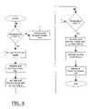
- FIG. 3is a flowchart illustrating the activation and operation of the present invention.
- FIG. 4is a flowchart illustrating the control of fluid flow through the present invention.
- FIG. 5is a chart illustrating the flow rate of the coolant based upon coolant temperature.
- FIG. 6is a flowchart illustrating an alternative embodiment of the activation and operation of the present invention.
- FIGS. 1 through 5illustrate a spray cooling system for extreme environments 10 , which comprises an enclosure 20 that isolates the electronic components from the external environment, a spray unit 30 within the enclosure 20 for thermally managing one or more electronic devices 12 , a pump unit 52 fluidly connected to the spray unit 30 , a heat exchanger unit 40 fluidly connected to the pump, and a control valve 42 fluidly connected between the heat exchanger unit 40 and the pump.
- An independent chamber 60preferably houses a heater unit 62 , a first power supply 64 and a control unit 66 , whereby the heater unit 62 initially heats the coolant within the independent chamber 60 to a minimum operating temperature prior to operation of the electronic components.
- the present inventionmay be utilized in various extreme environmental conditions including extreme external temperature conditions (e.g. ⁇ 65° C., +70° C.).
- the enclosure 20is comprised of a structure having at least one isolated internal compartment.
- the internal compartmentis preferably insulated from the external environment to reduce the heat transfer from within the internal compartment to the external environment.
- the enclosure 20may be comprised of various structures and configurations capable of isolating the internal compartment from the extreme elements and temperatures of the external environment.
- the spray unit 30is positioned within the internal compartment of the enclosure 20 .
- the spray unit 30preferably has a separate enclosed structure for retaining and thermally managing the electronic devices 12 .
- the spray unit 30may have an integral card cage spray assembly or similar structure for retaining the electronic devices 12 . More than one spray unit 30 may be utilized within the present invention.
- the spray unit 30may include one or more spray nozzles for applying atomized liquid coolant upon the electronic devices 12 .
- the spray unit 30may be comprised of various well-known spray cooling systems currently available for thermally managing electronic devices 12 with an atomized coolant.
- the heat exchanger unit 40is fluidly connected to the spray unit 30 via coolant path F 4 as shown in FIG. 1 of the drawings.
- the heat exchanger unit 40is preferably positioned externally of the enclosure 20 in direct contact with the external environment where the air temperature, density and flow rate may vary greatly.
- the heat exchanger unit 40may be comprised of various well-known structures commonly utilized within heat exchangers. More than one heat exchanger unit 40 may be utilized within the present invention.
- FIG. 2illustrates the electronic control system utilized within the present invention. More particularly, FIG. 2 illustrates a first temperature switch 68 and a second temperature switch 69 electrically connected to an input power.
- the input powermay be comprised of a battery supply, generator or the vehicle's power supply.
- the input powermay be comprised of alternating current (AC) or direct current (DC) operating at various voltage levels.
- a power filtermay be electrically connected between the input power and the power supplies.
- the temperature switchis electrically connected to and controls a heater unit 62 as further shown in FIG. 2 of the drawings.
- the first temperature switch 68is normally within a closed state when the coolant temperature is below a minimum operating temperature 1 (hereinafter “MOT 1 ”) thereby activating the heat unit to heat the coolant.
- the MOT 1is a minimum operating temperature required to operate the first power supply 64 , control unit 66 , pump unit 52 and control valve 42 .
- the MOT 1may have various temperature set points and temperature ranges such as but not limited to ⁇ 40° to ⁇ 35° Celsius.
- the first temperature switch 68preferably remains closed until the coolant temperature exceeds a minimum operating temperature 3 (hereinafter “MOT 3 ”).
- the MOT 3may have various temperature set points and temperature ranges such as but not limited to ⁇ 20° to ⁇ 10° Celsius.
- the second temperature switch 69is electrically connected to the first power supply 64 for providing electrical power to the first power supply 64 after the coolant temperature exceeds the MOT 1 .
- the control unit 66is in communication with the pump unit 52 and the control valve 42 for controlling the same.
- the control unit 66is further in communication with the second power supply 65 , wherein the second power supply 65 is electrically connected to the electronic devices 12 within the spray unit 30 to be thermally managed as shown in FIG. 2 of the drawings.
- the second power supply 65provides electrical power to the electronic devices 12 during normal operating conditions.
- the second power supply 65may be located within the independent chamber 60 or within the spray unit 30 .
- the control unit 66activates the second power supply 65 and after the coolant temperature exceeds the minimum operating temperature 2 (hereinafter “MOT 2 ”).
- the MOT 2is a temperature that is sufficient for the electronic devices 12 to operate.
- the MOT 2may have various temperature set points and temperature ranges such as but not limited to ⁇ 20° to ⁇ 10° Celsius.
- the control unit 66may be comprised of various electronic devices 12 capable of communicating with and controlling the electronic devices 12 , the spray unit 30 , the heat exchanger unit 40 , the pump unit 52 , valves, the control valve 42 and other devices.
- the control unit 66may be comprised of a computer or other electronic device capable of receiving and storing commands.
- the control unit 66may communicate with the external electrical devices such as but not limited to electrically or via communications signal. It can be appreciated that more than one control unit 66 may be utilized to control one or more of the components of the present invention.
- an independent chamber 60is preferably positioned within the enclosure 20 for housing the heater unit 62 , the first power supply 64 and the control unit 66 .
- the independent chamber 60is preferably fluidly connected to the pressurized side of the pump unit 52 for receiving the coolant during operation of the pump unit 52 .
- the heater unit 62is first activated (without the pump unit 52 operating) to first heat the coolant within the independent chamber 60 thereby increasing the temperature of the first power supply 64 and the control unit 66 to a minimum operating temperature.
- the first power supply 64is preferably positioned near the heater unit 62 thereby allowing the first power supply 64 to be heated initially as illustrated in FIG. 1 of the drawings.
- the coolant distribution system of the present inventionhas two basic flow patterns. Each flow pattern begins with the one or more attitude independent valves 50 that are fluidly connected to the spray unit 30 for collecting the coolant.
- the attitude independent valves 50may be positioned in various locations within the spray unit 30 for collecting a sufficient volume of liquid coolant during operation.
- Various other coolant collection devicesmay be utilized to collect the coolant from within the spray unit 30 .
- the coolant distribution system of the present inventionpreferably does not utilize a reservoir, however it can be appreciated that a coolant reservoir may be utilized.
- the attitude independent valves 50are fluidly connected to the pump unit 52 as illustrated in FIG. 1 of the drawings.
- the pump unit 52draws the liquid coolant and then dispenses the pressurized liquid coolant into the independent chamber 60 . It can be appreciated that a portion of the pressurized coolant may be diverted around the independent chamber 60 instead of passing through the independent chamber 60 .
- the pump unit 52forces the liquid coolant into the independent chamber 60 and then through flow path F 1 as shown in FIG. 1 of the drawings.
- the pump unit 52may be comprised of a conventional coolant pump and may be comprised of more than one pump.
- the independent chamber 60is fluidly connected to the control valve 42 as further shown in FIG. 1 of the drawings.
- the control valve 42controls the flow of the coolant through Path 1 (F 1 , F 2 , F 5 ) or Path 2 (F 1 , F 3 , F 4 , F 5 ) to the spray unit 30 .
- Path 1(F 1 , F 2 , F 5 ) provides a direct path for the coolant from the independent chamber 60 to the spray unit 30 without cooling through the heat exchanger unit 40 as shown in FIG. 1 of the drawings.
- Path 2(F 1 , F 3 , F 4 , F 5 ) diverts a portion of the coolant through the heat exchanger unit 40 to be cooled prior to the coolant entering the spray unit 30 as further shown in FIG. 1 of the drawings.
- the control valve 42controls the flow through Path 1 and Path 2 depending upon the temperature of the coolant. If the temperature of the coolant is less than temperature X, then the coolant flow is reduced through Path 2 and increased through Path 1 as shown in FIG. 4 of the drawings.
- the temperature Xmay have various temperature set points and temperature ranges such as but not limited to +40° to +50° Celsius. If the temperature of the coolant is greater than temperature X, then the coolant flow is increased through Path 2 and decreased through Path 1 as shown in FIG. 4 of the drawings.
- FIGS. 3 and 4provide the overall operation of the present invention. If the initial coolant temperature is less than or equal to the MOT 1 , then the first temperature switch 68 first activates the heater unit 62 prior to activating the pump unit 52 or other electrical components. The heater unit 62 heats the coolant within the independent chamber 60 as illustrated in FIG. 1 of the drawings. Since the first power supply 64 is preferably closest to the heater unit 62 , the first power supply 64 is initially increased in temperature. The control unit 66 is also increased in temperature since the control unit 66 is also positioned within the independent chamber 60 .
- the first power supply 64is activated by the second temperature switch 69 as shown in FIG. 3 of the drawings.
- the control unit 66is also activated thereby entering into an initialize and self-test procedure.
- the pump unit 52is also activated and operates at an initial flow rate A through both Path 1 and Path 2 as shown in FIGS. 3 and 4 of the drawings.
- FIG. 5 of the drawingsillustrates a chart showing an exemplary flow rate of the pump unit 52 based upon the coolant temperature. If the temperature of the coolant is below Temperature X, the control valve 42 reduces the coolant flow through Path 2 of the coolant distribution system.
- the control valve 42increases the coolant flow through Path 2 of the coolant distribution system to increase the cooling of the coolant by the external environment through the heat exchanger unit 40 .
- the coolant heated by the heater unit 62flows into the spray unit 30 thereby increasing the temperature of the electronic devices 12 and returns to the pump unit 52 through the attitude independent valves 50 .
- the coolant flow through the pump unit 52is increased to flow rate B as shown in FIG. 3 of the drawings.
- the second power supply 65is thereafter activated thereby providing electrical power to the electronic devices 12 as further shown in FIG. 3 of the drawings.
- the coolantis thereafter heated by both the heater unit 62 and the electronic devices 12 during normal operation. If the temperature of the coolant is below Temperature X, the control valve 42 reduces the coolant flow through Path 2 of the coolant distribution system as shown in FIG. 4 of the drawings.
- the control valve 42increases the coolant flow through Path 2 of the coolant distribution system to increase the cooling of the coolant by the external environment through the heat exchanger unit 40 . If the coolant temperature exceeds the MOT 3 , the heater unit 62 may either be terminated or reduced to decrease the heating of the coolant as shown in FIG. 3 of the drawings. Alternatively, the heater unit 62 may either be terminated or reduced to decrease the heating of the coolant immediately after the coolant temperature exceeds MOT 2 as shown in FIG. 6 of the drawings.
Landscapes
- Physics & Mathematics (AREA)
- Condensed Matter Physics & Semiconductors (AREA)
- General Physics & Mathematics (AREA)
- Engineering & Computer Science (AREA)
- Computer Hardware Design (AREA)
- Microelectronics & Electronic Packaging (AREA)
- Power Engineering (AREA)
- Cooling Or The Like Of Electrical Apparatus (AREA)
Abstract
Description
Claims (27)
Priority Applications (4)
| Application Number | Priority Date | Filing Date | Title |
|---|---|---|---|
| US10/369,321US6976528B1 (en) | 2003-02-18 | 2003-02-18 | Spray cooling system for extreme environments |
| US11/255,456US7264042B1 (en) | 2003-02-18 | 2005-10-24 | Spray cooling system for extreme environments |
| US11/255,457US7216695B1 (en) | 2003-02-18 | 2005-10-24 | Method of operating a thermal management system |
| US11/303,864US7806166B1 (en) | 2003-02-18 | 2005-12-15 | Insulated spray cooling system for extreme environments |
Applications Claiming Priority (1)
| Application Number | Priority Date | Filing Date | Title |
|---|---|---|---|
| US10/369,321US6976528B1 (en) | 2003-02-18 | 2003-02-18 | Spray cooling system for extreme environments |
Related Child Applications (3)
| Application Number | Title | Priority Date | Filing Date |
|---|---|---|---|
| US11/255,457ContinuationUS7216695B1 (en) | 2003-02-18 | 2005-10-24 | Method of operating a thermal management system |
| US11/255,456ContinuationUS7264042B1 (en) | 2003-02-18 | 2005-10-24 | Spray cooling system for extreme environments |
| US11/255,456Continuation-In-PartUS7264042B1 (en) | 2003-02-18 | 2005-10-24 | Spray cooling system for extreme environments |
Publications (1)
| Publication Number | Publication Date |
|---|---|
| US6976528B1true US6976528B1 (en) | 2005-12-20 |
Family
ID=35465466
Family Applications (3)
| Application Number | Title | Priority Date | Filing Date |
|---|---|---|---|
| US10/369,321Expired - LifetimeUS6976528B1 (en) | 2003-02-18 | 2003-02-18 | Spray cooling system for extreme environments |
| US11/255,457Expired - LifetimeUS7216695B1 (en) | 2003-02-18 | 2005-10-24 | Method of operating a thermal management system |
| US11/255,456Expired - LifetimeUS7264042B1 (en) | 2003-02-18 | 2005-10-24 | Spray cooling system for extreme environments |
Family Applications After (2)
| Application Number | Title | Priority Date | Filing Date |
|---|---|---|---|
| US11/255,457Expired - LifetimeUS7216695B1 (en) | 2003-02-18 | 2005-10-24 | Method of operating a thermal management system |
| US11/255,456Expired - LifetimeUS7264042B1 (en) | 2003-02-18 | 2005-10-24 | Spray cooling system for extreme environments |
Country Status (1)
| Country | Link |
|---|---|
| US (3) | US6976528B1 (en) |
Cited By (23)
| Publication number | Priority date | Publication date | Assignee | Title |
|---|---|---|---|---|
| US20060250775A1 (en)* | 2004-09-30 | 2006-11-09 | Saab Ab | A method for cooling electronic components in an unmanned flying vehicle and a device for carrying out the method |
| US7216695B1 (en)* | 2003-02-18 | 2007-05-15 | Isothermal Systems Research, Inc. | Method of operating a thermal management system |
| US20070144708A1 (en)* | 2005-12-22 | 2007-06-28 | Tilton Charles L | Passive Fluid Recovery System |
| US20070193285A1 (en)* | 2006-02-21 | 2007-08-23 | Knight Paul A | Testing for Leaks in a Two-Phase Liquid Cooling System |
| US20070193300A1 (en)* | 2006-02-21 | 2007-08-23 | Tilton Donald E | Two-phase liquid cooling system with active venting |
| US20070193721A1 (en)* | 2006-02-21 | 2007-08-23 | Tilton Donald E | Automated Venting and Refilling of Multiple Liquid Cooling Systems |
| WO2007142558A1 (en)* | 2006-06-02 | 2007-12-13 | Telefonaktiebolaget Lm Ericsson (Publ) | Temperature managing for electronic components |
| US20100103614A1 (en)* | 2008-10-23 | 2010-04-29 | International Business Machines Corporation | Apparatus and method for immersion-cooling of an electronic system utilizing coolant jet impingement and coolant wash flow |
| US7743619B1 (en)* | 2006-01-06 | 2010-06-29 | Isothermal Research Systems, Inc. | Heat exchanger system |
| US7916483B2 (en) | 2008-10-23 | 2011-03-29 | International Business Machines Corporation | Open flow cold plate for liquid cooled electronic packages |
| US7944694B2 (en) | 2008-10-23 | 2011-05-17 | International Business Machines Corporation | Liquid cooling apparatus and method for cooling blades of an electronic system chassis |
| US7961475B2 (en) | 2008-10-23 | 2011-06-14 | International Business Machines Corporation | Apparatus and method for facilitating immersion-cooling of an electronic subsystem |
| US7983040B2 (en) | 2008-10-23 | 2011-07-19 | International Business Machines Corporation | Apparatus and method for facilitating pumped immersion-cooling of an electronic subsystem |
| US20110277491A1 (en)* | 2010-02-12 | 2011-11-17 | MicroBase Technology Group | Heat dissipation system with a spray cooling device |
| US8179677B2 (en) | 2010-06-29 | 2012-05-15 | International Business Machines Corporation | Immersion-cooling apparatus and method for an electronic subsystem of an electronics rack |
| US8184436B2 (en) | 2010-06-29 | 2012-05-22 | International Business Machines Corporation | Liquid-cooled electronics rack with immersion-cooled electronic subsystems |
| US8345423B2 (en) | 2010-06-29 | 2013-01-01 | International Business Machines Corporation | Interleaved, immersion-cooling apparatuses and methods for cooling electronic subsystems |
| US20130000102A1 (en)* | 2007-07-19 | 2013-01-03 | Qwest Communications International Inc. | Protective Telecommunications Enclosure Systems and Methods |
| US8351206B2 (en) | 2010-06-29 | 2013-01-08 | International Business Machines Corporation | Liquid-cooled electronics rack with immersion-cooled electronic subsystems and vertically-mounted, vapor-condensing unit |
| US8369091B2 (en) | 2010-06-29 | 2013-02-05 | International Business Machines Corporation | Interleaved, immersion-cooling apparatus and method for an electronic subsystem of an electronics rack |
| US8671697B2 (en) | 2010-12-07 | 2014-03-18 | Parker-Hannifin Corporation | Pumping system resistant to cavitation |
| RU2534508C2 (en)* | 2013-02-15 | 2014-11-27 | Федеральное Государственное Бюджетное Образовательное Учреждение Высшего Профессионального Образования "Дагестанский Государственный Технический Университет" (Дгту) | Radio electronic equipment condensation cabinet |
| CN111298992A (en)* | 2019-12-04 | 2020-06-19 | 浙江大学建筑设计研究院有限公司 | Temperature control system of hypergravity centrifuge |
Families Citing this family (6)
| Publication number | Priority date | Publication date | Assignee | Title |
|---|---|---|---|---|
| US7349213B2 (en)* | 2006-06-29 | 2008-03-25 | International Business Machines Corporation | Coolant control unit, and cooled electronics system and method employing the same |
| US7405935B1 (en)* | 2006-11-28 | 2008-07-29 | Isothermal Systems Research, Inc. | Service tray for a thermal management system |
| US20090260795A1 (en)* | 2008-04-16 | 2009-10-22 | Perazzo Thomas M | Active door array for cooling system |
| US20120325436A1 (en) | 2011-06-27 | 2012-12-27 | Shedd Timothy A | High efficiency thermal management system |
| JP6376492B2 (en)* | 2013-09-10 | 2018-08-22 | パナソニックIpマネジメント株式会社 | Air cooling unit |
| CN110920914B (en)* | 2019-12-06 | 2021-04-06 | 南京航空航天大学 | Comprehensive thermal management and regulation system for airplane |
Citations (60)
| Publication number | Priority date | Publication date | Assignee | Title |
|---|---|---|---|---|
| US3213929A (en)* | 1962-02-12 | 1965-10-26 | Varian Associates | Temperature control system |
| US3406244A (en) | 1966-06-07 | 1968-10-15 | Ibm | Multi-liquid heat transfer |
| US3774661A (en) | 1970-03-19 | 1973-11-27 | Guilliet Ets | Method for cutting a shaped member from a wood block |
| US4399484A (en) | 1981-03-10 | 1983-08-16 | The United States Of America As Represented By The Secretary Of The Air Force | Integral electric module and assembly jet cooling system |
| EP0091733A1 (en) | 1982-03-09 | 1983-10-19 | BICC-Vero Electronics Limited | Cooling module for use in a circuit board array |
| US4897762A (en) | 1987-07-22 | 1990-01-30 | Hitachi, Ltd. | Cooling system and method for electronic circuit devices |
| US4912600A (en) | 1988-09-07 | 1990-03-27 | Auburn Univ. Of The State Of Alabama | Integrated circuit packaging and cooling |
| US4967829A (en) | 1987-12-09 | 1990-11-06 | Walter F. Albers | Heat and mass transfer rates by liquid spray impingement |
| US5021924A (en) | 1988-09-19 | 1991-06-04 | Hitachi, Ltd. | Semiconductor cooling device |
| EP0480750A2 (en) | 1990-10-11 | 1992-04-15 | Nec Corporation | Liquid cooling system for LSI packages |
| US5220804A (en) | 1991-12-09 | 1993-06-22 | Isothermal Systems Research, Inc | High heat flux evaporative spray cooling |
| US5293754A (en) | 1991-07-19 | 1994-03-15 | Nec Corporation | Liquid coolant circulating system |
| US5311931A (en) | 1991-12-27 | 1994-05-17 | The Research Foundation Of State University Of New York | Mist supercooling of a heated surface |
| US5349831A (en) | 1991-11-08 | 1994-09-27 | Hitachi, Ltd. | Apparatus for cooling heat generating members |
| US5515910A (en) | 1993-05-03 | 1996-05-14 | Micro Control System | Apparatus for burn-in of high power semiconductor devices |
| US5675473A (en) | 1996-02-23 | 1997-10-07 | Motorola, Inc. | Apparatus and method for shielding an electronic module from electromagnetic radiation |
| US5687577A (en) | 1996-04-10 | 1997-11-18 | Motorola, Inc. | Apparatus and method for spray-cooling an electronic module |
| US5719444A (en) | 1996-04-26 | 1998-02-17 | Tilton; Charles L. | Packaging and cooling system for power semi-conductor |
| US5718117A (en) | 1996-04-10 | 1998-02-17 | Motorola, Inc. | Apparatus and method for spray-cooling an electronic module |
| US5746585A (en) | 1996-12-31 | 1998-05-05 | Motorola, Inc. | Peristaltic pump and method in a peristaltic pump for advancing a tube from a first position to a second position |
| US5761035A (en) | 1996-06-28 | 1998-06-02 | Motorola, Inc. | Circuit board apparatus and method for spray-cooling a circuit board |
| US5768103A (en) | 1996-08-30 | 1998-06-16 | Motorola, Inc. | Circuit board apparatus and apparatus and method for spray-cooling an electronic component |
| US5818692A (en) | 1997-05-30 | 1998-10-06 | Motorola, Inc. | Apparatus and method for cooling an electrical component |
| US5831824A (en) | 1996-01-31 | 1998-11-03 | Motorola, Inc. | Apparatus for spray-cooling multiple electronic modules |
| US5841564A (en) | 1996-12-31 | 1998-11-24 | Motorola, Inc. | Apparatus for communication by an electronic device and method for communicating between electronic devices |
| US5860602A (en) | 1996-12-06 | 1999-01-19 | Tilton; Charles L | Laminated array of pressure swirl atomizers |
| US5880931A (en) | 1998-03-20 | 1999-03-09 | Tilton; Donald E. | Spray cooled circuit card cage |
| US5879503A (en) | 1996-09-23 | 1999-03-09 | Motorola, Inc. | Splicing tool and method for joining a first tube and a second tube |
| US5907473A (en) | 1997-04-04 | 1999-05-25 | Raytheon Company | Environmentally isolated enclosure for electronic components |
| US5924482A (en) | 1997-10-29 | 1999-07-20 | Motorola, Inc. | Multi-mode, two-phase cooling module |
| US5933700A (en) | 1998-09-21 | 1999-08-03 | Tilton; Charles L | Method for manufacturing pressure swirl atomizers |
| US5937937A (en) | 1998-06-18 | 1999-08-17 | Motorola, Inc. | Heat sink and method for removing heat from a plurality of components |
| US5943211A (en) | 1997-04-18 | 1999-08-24 | Raytheon Company | Heat spreader system for cooling heat generating components |
| US6061966A (en) | 1998-06-30 | 2000-05-16 | Emc Corporation | Electrical cabinet having a door stop |
| US6108201A (en) | 1999-02-22 | 2000-08-22 | Tilton; Charles L | Fluid control apparatus and method for spray cooling |
| US6115251A (en) | 1999-04-15 | 2000-09-05 | Hewlett Packard Company | Cooling apparatus for computer subsystem |
| US6129361A (en) | 1998-07-06 | 2000-10-10 | Ford Global Technologies, Inc. | Fluid conduit seal |
| US6134108A (en) | 1998-06-18 | 2000-10-17 | Hewlett-Packard Company | Apparatus and method for air-cooling an electronic assembly |
| WO2001001741A1 (en) | 1999-06-29 | 2001-01-04 | General Dynamics Information Systems, Inc. | Enclosure for spray cooling electronic modules |
| US6205799B1 (en) | 1999-09-13 | 2001-03-27 | Hewlett-Packard Company | Spray cooling system |
| US6292364B1 (en) | 2000-04-28 | 2001-09-18 | Raytheon Company | Liquid spray cooled module |
| US6330152B1 (en) | 2000-06-08 | 2001-12-11 | Lockheed Corp | Apparatus facilitating use of cots electronics in harsh environments |
| US6377458B1 (en) | 2000-07-31 | 2002-04-23 | Hewlett-Packard Company | Integrated EMI containment and spray cooling module utilizing a magnetically coupled pump |
| US6377453B1 (en) | 1999-01-29 | 2002-04-23 | Hewlett-Packard Company | Field replaceable module with enhanced thermal interface |
| US6414619B1 (en) | 1999-10-22 | 2002-07-02 | Eric J. Swanson | Autoranging analog to digital conversion circuitry |
| US20020113141A1 (en) | 2001-02-22 | 2002-08-22 | Malone Christopher G. | Passive spray coolant pump |
| US20020112496A1 (en) | 2001-02-22 | 2002-08-22 | Bash Cullen E. | Variably configured sprayjet cooling system |
| US20020112491A1 (en) | 2001-02-22 | 2002-08-22 | Malone Christopher G. | Spray cooling system with cooling regime detection |
| US20020113142A1 (en) | 2001-02-22 | 2002-08-22 | Patel Chandrakant D. | Spray cooling system for a device |
| US20020114140A1 (en) | 2001-02-22 | 2002-08-22 | Bash Cullen E. | Thermal connector for cooling electronics |
| US20020112498A1 (en) | 2001-02-22 | 2002-08-22 | Bash Cullen E. | Modular sprayjet cooling system |
| US20020114139A1 (en) | 2001-02-22 | 2002-08-22 | Bash Cullen E. | Thermal connection layer |
| US6447270B1 (en) | 1998-09-17 | 2002-09-10 | Walbro Corporation | Brushless coolant pump and cooling system |
| US20020135981A1 (en) | 2001-05-16 | 2002-09-26 | Cray Inc. | Method and apparatus for cooling electronic components |
| US6484521B2 (en) | 2001-02-22 | 2002-11-26 | Hewlett-Packard Company | Spray cooling with local control of nozzles |
| US6498725B2 (en) | 2001-05-01 | 2002-12-24 | Mainstream Engineering Corporation | Method and two-phase spray cooling apparatus |
| US20030039872A1 (en)* | 2001-08-22 | 2003-02-27 | Grasso Albert P. | Freeze tolerant fuel cell power plant |
| US6571569B1 (en) | 2001-04-26 | 2003-06-03 | Rini Technologies, Inc. | Method and apparatus for high heat flux heat transfer |
| US6651761B1 (en)* | 2001-09-27 | 2003-11-25 | Ford Global Technologies, Llc | Temperature control system for fuel cell electric vehicle cooling circuit |
| US6679081B2 (en) | 2000-04-04 | 2004-01-20 | Thermal Form & Function, Llc | Pumped liquid cooling system using a phase change refrigerant |
Family Cites Families (6)
| Publication number | Priority date | Publication date | Assignee | Title |
|---|---|---|---|---|
| US2643282A (en)* | 1949-04-13 | 1953-06-23 | Albert D Greene | Electronic equipment cooling means |
| FR2580060B1 (en)* | 1985-04-05 | 1989-06-09 | Nec Corp | |
| US4800952A (en)* | 1987-07-22 | 1989-01-31 | General Electric Company | Thaw flow control for liquid heat transport systems |
| US6673481B1 (en)* | 2002-07-01 | 2004-01-06 | Utc Fuel Cells, Llc | Initiating operation of an electric vehicle or other load powered by a fuel cell at sub-freezing temperature |
| US6986958B2 (en)* | 2003-02-06 | 2006-01-17 | Utc Fuel Cells, Llc | Fuel cell stack melting of coolant water during frozen startup |
| US6976528B1 (en)* | 2003-02-18 | 2005-12-20 | Isothermal Systems Research, Inc. | Spray cooling system for extreme environments |
- 2003
- 2003-02-18USUS10/369,321patent/US6976528B1/ennot_activeExpired - Lifetime
- 2005
- 2005-10-24USUS11/255,457patent/US7216695B1/ennot_activeExpired - Lifetime
- 2005-10-24USUS11/255,456patent/US7264042B1/ennot_activeExpired - Lifetime
Patent Citations (70)
| Publication number | Priority date | Publication date | Assignee | Title |
|---|---|---|---|---|
| US3213929A (en)* | 1962-02-12 | 1965-10-26 | Varian Associates | Temperature control system |
| US3406244A (en) | 1966-06-07 | 1968-10-15 | Ibm | Multi-liquid heat transfer |
| US3774661A (en) | 1970-03-19 | 1973-11-27 | Guilliet Ets | Method for cutting a shaped member from a wood block |
| US4399484A (en) | 1981-03-10 | 1983-08-16 | The United States Of America As Represented By The Secretary Of The Air Force | Integral electric module and assembly jet cooling system |
| EP0091733A1 (en) | 1982-03-09 | 1983-10-19 | BICC-Vero Electronics Limited | Cooling module for use in a circuit board array |
| US4897762A (en) | 1987-07-22 | 1990-01-30 | Hitachi, Ltd. | Cooling system and method for electronic circuit devices |
| US4967829A (en) | 1987-12-09 | 1990-11-06 | Walter F. Albers | Heat and mass transfer rates by liquid spray impingement |
| US4912600A (en) | 1988-09-07 | 1990-03-27 | Auburn Univ. Of The State Of Alabama | Integrated circuit packaging and cooling |
| US5021924A (en) | 1988-09-19 | 1991-06-04 | Hitachi, Ltd. | Semiconductor cooling device |
| EP0480750A2 (en) | 1990-10-11 | 1992-04-15 | Nec Corporation | Liquid cooling system for LSI packages |
| US5522452A (en)* | 1990-10-11 | 1996-06-04 | Nec Corporation | Liquid cooling system for LSI packages |
| US5293754A (en) | 1991-07-19 | 1994-03-15 | Nec Corporation | Liquid coolant circulating system |
| US5349831A (en) | 1991-11-08 | 1994-09-27 | Hitachi, Ltd. | Apparatus for cooling heat generating members |
| US5220804A (en) | 1991-12-09 | 1993-06-22 | Isothermal Systems Research, Inc | High heat flux evaporative spray cooling |
| US5311931A (en) | 1991-12-27 | 1994-05-17 | The Research Foundation Of State University Of New York | Mist supercooling of a heated surface |
| US5579826A (en)* | 1993-05-03 | 1996-12-03 | Micro Control Company | Method for burn-in of high power semiconductor devices |
| US5515910A (en) | 1993-05-03 | 1996-05-14 | Micro Control System | Apparatus for burn-in of high power semiconductor devices |
| US5831824A (en) | 1996-01-31 | 1998-11-03 | Motorola, Inc. | Apparatus for spray-cooling multiple electronic modules |
| US5675473A (en) | 1996-02-23 | 1997-10-07 | Motorola, Inc. | Apparatus and method for shielding an electronic module from electromagnetic radiation |
| US5687577A (en) | 1996-04-10 | 1997-11-18 | Motorola, Inc. | Apparatus and method for spray-cooling an electronic module |
| US5718117A (en) | 1996-04-10 | 1998-02-17 | Motorola, Inc. | Apparatus and method for spray-cooling an electronic module |
| US5719444A (en) | 1996-04-26 | 1998-02-17 | Tilton; Charles L. | Packaging and cooling system for power semi-conductor |
| US5761035A (en) | 1996-06-28 | 1998-06-02 | Motorola, Inc. | Circuit board apparatus and method for spray-cooling a circuit board |
| US5768103A (en) | 1996-08-30 | 1998-06-16 | Motorola, Inc. | Circuit board apparatus and apparatus and method for spray-cooling an electronic component |
| US5879503A (en) | 1996-09-23 | 1999-03-09 | Motorola, Inc. | Splicing tool and method for joining a first tube and a second tube |
| US6016969A (en) | 1996-12-06 | 2000-01-25 | Tilton; Charles | Laminated array of pressure swirl atomizers |
| US5860602A (en) | 1996-12-06 | 1999-01-19 | Tilton; Charles L | Laminated array of pressure swirl atomizers |
| US5841564A (en) | 1996-12-31 | 1998-11-24 | Motorola, Inc. | Apparatus for communication by an electronic device and method for communicating between electronic devices |
| US5746585A (en) | 1996-12-31 | 1998-05-05 | Motorola, Inc. | Peristaltic pump and method in a peristaltic pump for advancing a tube from a first position to a second position |
| US6014238A (en) | 1996-12-31 | 2000-01-11 | Motorola, Inc. | Apparatus for communication by an electronic device and method for communicating between electronic devices |
| US6139361A (en)* | 1997-04-04 | 2000-10-31 | Raytheon Company | Hermetic connector for a closed compartment |
| US5907473A (en) | 1997-04-04 | 1999-05-25 | Raytheon Company | Environmentally isolated enclosure for electronic components |
| US5943211A (en) | 1997-04-18 | 1999-08-24 | Raytheon Company | Heat spreader system for cooling heat generating components |
| US5818692A (en) | 1997-05-30 | 1998-10-06 | Motorola, Inc. | Apparatus and method for cooling an electrical component |
| US5924482A (en) | 1997-10-29 | 1999-07-20 | Motorola, Inc. | Multi-mode, two-phase cooling module |
| US5880931A (en) | 1998-03-20 | 1999-03-09 | Tilton; Donald E. | Spray cooled circuit card cage |
| US6134108A (en) | 1998-06-18 | 2000-10-17 | Hewlett-Packard Company | Apparatus and method for air-cooling an electronic assembly |
| US5937937A (en) | 1998-06-18 | 1999-08-17 | Motorola, Inc. | Heat sink and method for removing heat from a plurality of components |
| US6061966A (en) | 1998-06-30 | 2000-05-16 | Emc Corporation | Electrical cabinet having a door stop |
| US6129361A (en) | 1998-07-06 | 2000-10-10 | Ford Global Technologies, Inc. | Fluid conduit seal |
| US6447270B1 (en) | 1998-09-17 | 2002-09-10 | Walbro Corporation | Brushless coolant pump and cooling system |
| US5933700A (en) | 1998-09-21 | 1999-08-03 | Tilton; Charles L | Method for manufacturing pressure swirl atomizers |
| US6377453B1 (en) | 1999-01-29 | 2002-04-23 | Hewlett-Packard Company | Field replaceable module with enhanced thermal interface |
| US6108201A (en) | 1999-02-22 | 2000-08-22 | Tilton; Charles L | Fluid control apparatus and method for spray cooling |
| US6115251A (en) | 1999-04-15 | 2000-09-05 | Hewlett Packard Company | Cooling apparatus for computer subsystem |
| WO2001001741A1 (en) | 1999-06-29 | 2001-01-04 | General Dynamics Information Systems, Inc. | Enclosure for spray cooling electronic modules |
| US20020050144A1 (en) | 1999-09-13 | 2002-05-02 | Patel Chandrakant D. | Spray cooling system |
| US6349554B2 (en) | 1999-09-13 | 2002-02-26 | Hewlett-Packard Company | Spray cooling system |
| US20010002541A1 (en) | 1999-09-13 | 2001-06-07 | Patel Chandrakant D. | Spray cooling system |
| US6457321B1 (en) | 1999-09-13 | 2002-10-01 | Hewlett-Packard Company | Spray cooling system |
| US6205799B1 (en) | 1999-09-13 | 2001-03-27 | Hewlett-Packard Company | Spray cooling system |
| US6414619B1 (en) | 1999-10-22 | 2002-07-02 | Eric J. Swanson | Autoranging analog to digital conversion circuitry |
| US6679081B2 (en) | 2000-04-04 | 2004-01-20 | Thermal Form & Function, Llc | Pumped liquid cooling system using a phase change refrigerant |
| US6292364B1 (en) | 2000-04-28 | 2001-09-18 | Raytheon Company | Liquid spray cooled module |
| US6330152B1 (en) | 2000-06-08 | 2001-12-11 | Lockheed Corp | Apparatus facilitating use of cots electronics in harsh environments |
| US6377458B1 (en) | 2000-07-31 | 2002-04-23 | Hewlett-Packard Company | Integrated EMI containment and spray cooling module utilizing a magnetically coupled pump |
| US20020075650A1 (en) | 2000-07-31 | 2002-06-20 | Morris Terrel L. | Integrated EMI containment and spray cooling module utilizing a magnetically coupled pump |
| US20020113142A1 (en) | 2001-02-22 | 2002-08-22 | Patel Chandrakant D. | Spray cooling system for a device |
| US20020114140A1 (en) | 2001-02-22 | 2002-08-22 | Bash Cullen E. | Thermal connector for cooling electronics |
| US20020112498A1 (en) | 2001-02-22 | 2002-08-22 | Bash Cullen E. | Modular sprayjet cooling system |
| US20020114139A1 (en) | 2001-02-22 | 2002-08-22 | Bash Cullen E. | Thermal connection layer |
| US20020112491A1 (en) | 2001-02-22 | 2002-08-22 | Malone Christopher G. | Spray cooling system with cooling regime detection |
| US20020112496A1 (en) | 2001-02-22 | 2002-08-22 | Bash Cullen E. | Variably configured sprayjet cooling system |
| US6484521B2 (en) | 2001-02-22 | 2002-11-26 | Hewlett-Packard Company | Spray cooling with local control of nozzles |
| US20020113141A1 (en) | 2001-02-22 | 2002-08-22 | Malone Christopher G. | Passive spray coolant pump |
| US6571569B1 (en) | 2001-04-26 | 2003-06-03 | Rini Technologies, Inc. | Method and apparatus for high heat flux heat transfer |
| US6498725B2 (en) | 2001-05-01 | 2002-12-24 | Mainstream Engineering Corporation | Method and two-phase spray cooling apparatus |
| US20020135981A1 (en) | 2001-05-16 | 2002-09-26 | Cray Inc. | Method and apparatus for cooling electronic components |
| US20030039872A1 (en)* | 2001-08-22 | 2003-02-27 | Grasso Albert P. | Freeze tolerant fuel cell power plant |
| US6651761B1 (en)* | 2001-09-27 | 2003-11-25 | Ford Global Technologies, Llc | Temperature control system for fuel cell electric vehicle cooling circuit |
Non-Patent Citations (17)
| Title |
|---|
| Advanced System Packaging for Embedded High Perfoirmance Computing, Sienski, Ken, et al. |
| Advanced Thermal Management for High Density Distributed Power Systems, Smetana, Bruce A. et al., HFPC Conference, May 1995. |
| Advanced Thermal Management for Multichip Modules, Tilton, Donald E. et al., Electronic Packaging & Production, Aug. 1995. |
| Applying Mist to COTS Convection Modules Is Really Cool, Tilton, Charles, COTS View, 2000. |
| Closed-System High-Flux Evaporative Spray Coolling, Tilton, Donald E. et al., SAE Paper 892316 Aerotech 89 Anneheim, CA. |
| Critical Heat Flux Penomena in Spray Cooling, Tilton, Donald E. et al., AIAA Paper 90-1729, AIAA/ASME 5<SUP>th </SUP>Joint Thermophysics and Heat Transfer Conf., Seattle, WA, Jun. 1990. |
| High-Flux Spray Cooling in a Simulated Multichip Module, Tilton, Donald E. et al., ASME 1992 National Heat Transfer Conference, San Diego, CA, 1992. |
| High-Heat-Flux, Low-Superheat Evaporative Spray Cooling, Pais, M.R. et al., AIAA Paper AIRR-89-0241, 27<SUP>th </SUP>Aerospace Sciences Meeting, Reno, Nevada, 1989. |
| High-Performance COTS DSP for Harsh Environment VME Electronics, Tilton, Donald E. et al., COTS Journal, May/Jun. 1999. |
| Isothermal Systems Research-Way Cool Spray Cool, Isothermal Systems Research-David D. Tilton, www.navysbir.brtrc.com/SuccessStories/IsothermalSystems.pdf. |
| Liquid Nitrogen Spray Cooling of a Simulated Electronic Chip, Tilton, Donald E. et al., Proceedings of the 1993 Cryogenic Engineering Conference, Albuquerque, New Mexico, Jul. 1993. |
| Mist Cooling for Harsh Environment VME, Tilton, Donald E. et al., RTC Magazine, May 1999. |
| Spray Cooling at Low System Pressure, Marcos, A., et al., 18<SUP>th </SUP>IEEE Semi-Therm Symposium, 2002. |
| Spray Cooling for the 3-D Cube Computer, Tilton, Donald E. et al., InterSociety Conference on Thermal Phenomena in Electronic Systems, 1-THERM IV, Washington D.C., May 1994. |
| Spray Cooling of Simulated Electronic Chips in a Compact Package, Tilton, Donald E. et al., Final Report, Air Force Contract F33615-89-C-2972, Oct. 1991. |
| Spray Cooling, Tilton, Donald E., PhD Dissertation, University of Kentucky, 1989. |
| SprayCool Enclosure Products, Isothermal Systems Research Website, www.spraycool.com. |
Cited By (34)
| Publication number | Priority date | Publication date | Assignee | Title |
|---|---|---|---|---|
| US7216695B1 (en)* | 2003-02-18 | 2007-05-15 | Isothermal Systems Research, Inc. | Method of operating a thermal management system |
| US7264042B1 (en)* | 2003-02-18 | 2007-09-04 | Isothermal Systems Research, Inc. | Spray cooling system for extreme environments |
| US7561424B2 (en)* | 2004-09-30 | 2009-07-14 | Saab Ab | Method for cooling electronic components in an unmanned flying vehicle and a device for carrying out the method |
| US20060250775A1 (en)* | 2004-09-30 | 2006-11-09 | Saab Ab | A method for cooling electronic components in an unmanned flying vehicle and a device for carrying out the method |
| US20070144708A1 (en)* | 2005-12-22 | 2007-06-28 | Tilton Charles L | Passive Fluid Recovery System |
| US7779896B2 (en) | 2005-12-22 | 2010-08-24 | Parker-Hannifin Corporation | Passive fluid recovery system |
| US7717162B2 (en) | 2005-12-22 | 2010-05-18 | Isothermal Systems Research, Inc. | Passive fluid recovery system |
| US20080066892A1 (en)* | 2005-12-22 | 2008-03-20 | Isothermal Systems Research, Inc. | Passive Fluid Recovery System |
| WO2007076090A3 (en)* | 2005-12-22 | 2008-03-27 | Isothermal Systems Res Inc | Passive fluid recovery system |
| US7743619B1 (en)* | 2006-01-06 | 2010-06-29 | Isothermal Research Systems, Inc. | Heat exchanger system |
| US20070193300A1 (en)* | 2006-02-21 | 2007-08-23 | Tilton Donald E | Two-phase liquid cooling system with active venting |
| US20070193721A1 (en)* | 2006-02-21 | 2007-08-23 | Tilton Donald E | Automated Venting and Refilling of Multiple Liquid Cooling Systems |
| US20070193285A1 (en)* | 2006-02-21 | 2007-08-23 | Knight Paul A | Testing for Leaks in a Two-Phase Liquid Cooling System |
| US20090283248A1 (en)* | 2006-06-02 | 2009-11-19 | Nilsson Torbjoern | Temperature Managing For Electronic Components |
| WO2007142558A1 (en)* | 2006-06-02 | 2007-12-13 | Telefonaktiebolaget Lm Ericsson (Publ) | Temperature managing for electronic components |
| US9124956B2 (en)* | 2007-07-19 | 2015-09-01 | Qwest Communications International Inc. | Method of producing a high-altitude electromagnetic pulse protected enclosure |
| US20130000102A1 (en)* | 2007-07-19 | 2013-01-03 | Qwest Communications International Inc. | Protective Telecommunications Enclosure Systems and Methods |
| US7885070B2 (en)* | 2008-10-23 | 2011-02-08 | International Business Machines Corporation | Apparatus and method for immersion-cooling of an electronic system utilizing coolant jet impingement and coolant wash flow |
| US7916483B2 (en) | 2008-10-23 | 2011-03-29 | International Business Machines Corporation | Open flow cold plate for liquid cooled electronic packages |
| US7961475B2 (en) | 2008-10-23 | 2011-06-14 | International Business Machines Corporation | Apparatus and method for facilitating immersion-cooling of an electronic subsystem |
| US7983040B2 (en) | 2008-10-23 | 2011-07-19 | International Business Machines Corporation | Apparatus and method for facilitating pumped immersion-cooling of an electronic subsystem |
| US7944694B2 (en) | 2008-10-23 | 2011-05-17 | International Business Machines Corporation | Liquid cooling apparatus and method for cooling blades of an electronic system chassis |
| US20100103614A1 (en)* | 2008-10-23 | 2010-04-29 | International Business Machines Corporation | Apparatus and method for immersion-cooling of an electronic system utilizing coolant jet impingement and coolant wash flow |
| US8203842B2 (en) | 2008-10-23 | 2012-06-19 | International Business Machines Corporation | Open flow cold plate for immersion-cooled electronic packages |
| US20110277491A1 (en)* | 2010-02-12 | 2011-11-17 | MicroBase Technology Group | Heat dissipation system with a spray cooling device |
| US8179677B2 (en) | 2010-06-29 | 2012-05-15 | International Business Machines Corporation | Immersion-cooling apparatus and method for an electronic subsystem of an electronics rack |
| US8345423B2 (en) | 2010-06-29 | 2013-01-01 | International Business Machines Corporation | Interleaved, immersion-cooling apparatuses and methods for cooling electronic subsystems |
| US8351206B2 (en) | 2010-06-29 | 2013-01-08 | International Business Machines Corporation | Liquid-cooled electronics rack with immersion-cooled electronic subsystems and vertically-mounted, vapor-condensing unit |
| US8369091B2 (en) | 2010-06-29 | 2013-02-05 | International Business Machines Corporation | Interleaved, immersion-cooling apparatus and method for an electronic subsystem of an electronics rack |
| US8184436B2 (en) | 2010-06-29 | 2012-05-22 | International Business Machines Corporation | Liquid-cooled electronics rack with immersion-cooled electronic subsystems |
| US8671697B2 (en) | 2010-12-07 | 2014-03-18 | Parker-Hannifin Corporation | Pumping system resistant to cavitation |
| RU2534508C2 (en)* | 2013-02-15 | 2014-11-27 | Федеральное Государственное Бюджетное Образовательное Учреждение Высшего Профессионального Образования "Дагестанский Государственный Технический Университет" (Дгту) | Radio electronic equipment condensation cabinet |
| CN111298992A (en)* | 2019-12-04 | 2020-06-19 | 浙江大学建筑设计研究院有限公司 | Temperature control system of hypergravity centrifuge |
| CN111298992B (en)* | 2019-12-04 | 2024-10-29 | 浙江大学建筑设计研究院有限公司 | Temperature control system of supergravity centrifugal machine |
Also Published As
| Publication number | Publication date |
|---|---|
| US7216695B1 (en) | 2007-05-15 |
| US7264042B1 (en) | 2007-09-04 |
Similar Documents
| Publication | Publication Date | Title |
|---|---|---|
| US6976528B1 (en) | Spray cooling system for extreme environments | |
| US7806166B1 (en) | Insulated spray cooling system for extreme environments | |
| US5907473A (en) | Environmentally isolated enclosure for electronic components | |
| US4635709A (en) | Dual mode heat exchanger | |
| US6931834B2 (en) | Cooling systems | |
| US6330152B1 (en) | Apparatus facilitating use of cots electronics in harsh environments | |
| US7000691B1 (en) | Method and apparatus for cooling with coolant at a subambient pressure | |
| EP2628680B1 (en) | Integrated environmental control systems and methods for controlling environmental temperature of an enclosed space | |
| US2925722A (en) | Expendable liquid evaporative coolant system | |
| EP1909549A2 (en) | Electronic chassis having a plurality of phase change material reservoirs | |
| Ohadi et al. | Thermal management of harsh-environment electronics | |
| US20080302505A1 (en) | Evaporative cooling system | |
| WO2001007855A1 (en) | Thermal management apparatus for a sealed enclosure | |
| EP0584920B1 (en) | Thermal control system | |
| US6552901B2 (en) | Apparatus and system for cooling electronic circuitry, heat sinks, and related components | |
| US7180741B1 (en) | Spray cool system with a dry access chamber | |
| EP3339789B1 (en) | Passive cooling system using a dual-phase fluid, particularly for cooling electronic apparatuses, such as avionic apparatuses | |
| US12245407B2 (en) | Aircraft and method for thermal management | |
| EP1643822A1 (en) | A method for cooling electronic components in an unmanned flying vehicle and a device for carrying out the method | |
| US7643910B1 (en) | Spray chamber valve control system | |
| US12360580B2 (en) | Environmental control system for computing hardware in an autonomous driving vehicle | |
| US7428152B1 (en) | Localized thermal management system | |
| AU3437202A (en) | Hermetic connector for a closed compartment | |
| HK1256119B (en) | Passive cooling system using a dual-phase fluid, particularly for cooling electronic apparatuses, such as avionic apparatuses |
Legal Events
| Date | Code | Title | Description |
|---|---|---|---|
| AS | Assignment | Owner name:ISOTHERMAL SYSTEMS RESEARCH, INC., WASHINGTON Free format text:ASSIGNMENT OF ASSIGNORS INTEREST;ASSIGNORS:TILTON, CHARLES L.;MILLER, DOULGAS W.;GUSTAFSON, WILLIAM C;AND OTHERS;REEL/FRAME:013909/0045;SIGNING DATES FROM 20030305 TO 20030310 | |
| STCF | Information on status: patent grant | Free format text:PATENTED CASE | |
| AS | Assignment | Owner name:SILICON VALLEY BANK, CALIFORNIA Free format text:SECURITY AGREEMENT;ASSIGNOR:ISOTHERMAL SYSTEMS RESEARCH, INC.;REEL/FRAME:019733/0853 Effective date:20070816 | |
| FPAY | Fee payment | Year of fee payment:4 | |
| AS | Assignment | Owner name:ISOTHERMAL SYSTEMS RESEARCH INC.,WASHINGTON Free format text:RELEASE;ASSIGNOR:SILICON VALLEY BANK;REEL/FRAME:024035/0511 Effective date:20100303 | |
| AS | Assignment | Owner name:PARKER INTANGIBLES LLC,OHIO Free format text:ASSIGNMENT OF ASSIGNORS INTEREST;ASSIGNOR:ISOTHERMAL SYSTEMS RESEARCH, INC.;REEL/FRAME:024294/0473 Effective date:20100301 Owner name:PARKER INTANGIBLES LLC, OHIO Free format text:ASSIGNMENT OF ASSIGNORS INTEREST;ASSIGNOR:ISOTHERMAL SYSTEMS RESEARCH, INC.;REEL/FRAME:024294/0473 Effective date:20100301 | |
| FPAY | Fee payment | Year of fee payment:8 | |
| FPAY | Fee payment | Year of fee payment:12 |