US6976087B1 - Service provisioning methods and apparatus - Google Patents
Service provisioning methods and apparatusDownload PDFInfo
- Publication number
- US6976087B1 US6976087B1US09/990,561US99056101AUS6976087B1US 6976087 B1US6976087 B1US 6976087B1US 99056101 AUS99056101 AUS 99056101AUS 6976087 B1US6976087 B1US 6976087B1
- Authority
- US
- United States
- Prior art keywords
- bandwidth
- data
- link
- network
- data connection
- Prior art date
- Legal status (The legal status is an assumption and is not a legal conclusion. Google has not performed a legal analysis and makes no representation as to the accuracy of the status listed.)
- Expired - Lifetime, expires
Links
- 238000000034methodMethods0.000titleclaimsdescription73
- 238000013480data collectionMethods0.000claimsabstractdescription40
- 230000007246mechanismEffects0.000claimsdescription26
- 238000013519translationMethods0.000claimsdescription24
- 238000004891communicationMethods0.000claimsdescription20
- 230000008859changeEffects0.000claimsdescription18
- 238000012546transferMethods0.000claimsdescription8
- 238000004422calculation algorithmMethods0.000description34
- 230000008569processEffects0.000description28
- 230000001934delayEffects0.000description24
- 238000010586diagramMethods0.000description24
- 230000005540biological transmissionEffects0.000description11
- 238000007726management methodMethods0.000description11
- 238000010200validation analysisMethods0.000description11
- 238000005516engineering processMethods0.000description9
- 238000012545processingMethods0.000description8
- 239000000969carrierSubstances0.000description7
- 238000002167anodic stripping potentiometryMethods0.000description6
- 206010003664atrial septal defectDiseases0.000description6
- 230000006870functionEffects0.000description6
- 238000001514detection methodMethods0.000description3
- 230000000694effectsEffects0.000description3
- 238000005259measurementMethods0.000description3
- 238000003339best practiceMethods0.000description2
- 230000001419dependent effectEffects0.000description2
- 238000011156evaluationMethods0.000description2
- 241001441724TetraodontidaeSpecies0.000description1
- 230000004075alterationEffects0.000description1
- 238000000137annealingMethods0.000description1
- 238000013459approachMethods0.000description1
- 230000008901benefitEffects0.000description1
- 239000006227byproductSubstances0.000description1
- 238000004364calculation methodMethods0.000description1
- 230000008867communication pathwayEffects0.000description1
- 238000004883computer applicationMethods0.000description1
- 238000011960computer-aided designMethods0.000description1
- 238000013461designMethods0.000description1
- 230000002708enhancing effectEffects0.000description1
- 238000012248genetic selectionMethods0.000description1
- 230000000977initiatory effectEffects0.000description1
- 230000002452interceptive effectEffects0.000description1
- 238000012986modificationMethods0.000description1
- 230000004048modificationEffects0.000description1
- 230000000737periodic effectEffects0.000description1
- 238000013439planningMethods0.000description1
- 238000013138pruningMethods0.000description1
- 238000007493shaping processMethods0.000description1
- 230000001502supplementing effectEffects0.000description1
- 230000002123temporal effectEffects0.000description1
- 238000012384transportation and deliveryMethods0.000description1
- 238000011144upstream manufacturingMethods0.000description1
Images


Classifications
- H—ELECTRICITY
- H04—ELECTRIC COMMUNICATION TECHNIQUE
- H04L—TRANSMISSION OF DIGITAL INFORMATION, e.g. TELEGRAPHIC COMMUNICATION
- H04L43/00—Arrangements for monitoring or testing data switching networks
- H04L43/08—Monitoring or testing based on specific metrics, e.g. QoS, energy consumption or environmental parameters
- H04L43/0852—Delays
- H04L43/087—Jitter
- H—ELECTRICITY
- H04—ELECTRIC COMMUNICATION TECHNIQUE
- H04L—TRANSMISSION OF DIGITAL INFORMATION, e.g. TELEGRAPHIC COMMUNICATION
- H04L47/00—Traffic control in data switching networks
- H04L47/10—Flow control; Congestion control
- H04L47/15—Flow control; Congestion control in relation to multipoint traffic
- H—ELECTRICITY
- H04—ELECTRIC COMMUNICATION TECHNIQUE
- H04L—TRANSMISSION OF DIGITAL INFORMATION, e.g. TELEGRAPHIC COMMUNICATION
- H04L47/00—Traffic control in data switching networks
- H04L47/10—Flow control; Congestion control
- H04L47/24—Traffic characterised by specific attributes, e.g. priority or QoS
- H04L47/2441—Traffic characterised by specific attributes, e.g. priority or QoS relying on flow classification, e.g. using integrated services [IntServ]
- H—ELECTRICITY
- H04—ELECTRIC COMMUNICATION TECHNIQUE
- H04L—TRANSMISSION OF DIGITAL INFORMATION, e.g. TELEGRAPHIC COMMUNICATION
- H04L47/00—Traffic control in data switching networks
- H04L47/10—Flow control; Congestion control
- H04L47/28—Flow control; Congestion control in relation to timing considerations
- H04L47/283—Flow control; Congestion control in relation to timing considerations in response to processing delays, e.g. caused by jitter or round trip time [RTT]
- H—ELECTRICITY
- H04—ELECTRIC COMMUNICATION TECHNIQUE
- H04L—TRANSMISSION OF DIGITAL INFORMATION, e.g. TELEGRAPHIC COMMUNICATION
- H04L47/00—Traffic control in data switching networks
- H04L47/10—Flow control; Congestion control
- H04L47/32—Flow control; Congestion control by discarding or delaying data units, e.g. packets or frames
- H—ELECTRICITY
- H04—ELECTRIC COMMUNICATION TECHNIQUE
- H04L—TRANSMISSION OF DIGITAL INFORMATION, e.g. TELEGRAPHIC COMMUNICATION
- H04L47/00—Traffic control in data switching networks
- H04L47/10—Flow control; Congestion control
- H04L47/36—Flow control; Congestion control by determining packet size, e.g. maximum transfer unit [MTU]
- H—ELECTRICITY
- H04—ELECTRIC COMMUNICATION TECHNIQUE
- H04L—TRANSMISSION OF DIGITAL INFORMATION, e.g. TELEGRAPHIC COMMUNICATION
- H04L47/00—Traffic control in data switching networks
- H04L47/70—Admission control; Resource allocation
- H—ELECTRICITY
- H04—ELECTRIC COMMUNICATION TECHNIQUE
- H04L—TRANSMISSION OF DIGITAL INFORMATION, e.g. TELEGRAPHIC COMMUNICATION
- H04L47/00—Traffic control in data switching networks
- H04L47/70—Admission control; Resource allocation
- H04L47/72—Admission control; Resource allocation using reservation actions during connection setup
- H04L47/724—Admission control; Resource allocation using reservation actions during connection setup at intermediate nodes, e.g. resource reservation protocol [RSVP]
- H—ELECTRICITY
- H04—ELECTRIC COMMUNICATION TECHNIQUE
- H04L—TRANSMISSION OF DIGITAL INFORMATION, e.g. TELEGRAPHIC COMMUNICATION
- H04L47/00—Traffic control in data switching networks
- H04L47/70—Admission control; Resource allocation
- H04L47/76—Admission control; Resource allocation using dynamic resource allocation, e.g. in-call renegotiation requested by the user or requested by the network in response to changing network conditions
- H04L47/762—Admission control; Resource allocation using dynamic resource allocation, e.g. in-call renegotiation requested by the user or requested by the network in response to changing network conditions triggered by the network
- H—ELECTRICITY
- H04—ELECTRIC COMMUNICATION TECHNIQUE
- H04L—TRANSMISSION OF DIGITAL INFORMATION, e.g. TELEGRAPHIC COMMUNICATION
- H04L47/00—Traffic control in data switching networks
- H04L47/70—Admission control; Resource allocation
- H04L47/82—Miscellaneous aspects
- H04L47/822—Collecting or measuring resource availability data
- H—ELECTRICITY
- H04—ELECTRIC COMMUNICATION TECHNIQUE
- H04L—TRANSMISSION OF DIGITAL INFORMATION, e.g. TELEGRAPHIC COMMUNICATION
- H04L47/00—Traffic control in data switching networks
- H04L47/70—Admission control; Resource allocation
- H04L47/82—Miscellaneous aspects
- H04L47/829—Topology based
- H—ELECTRICITY
- H04—ELECTRIC COMMUNICATION TECHNIQUE
- H04L—TRANSMISSION OF DIGITAL INFORMATION, e.g. TELEGRAPHIC COMMUNICATION
- H04L49/00—Packet switching elements
- H04L49/90—Buffering arrangements
- H04L49/9023—Buffering arrangements for implementing a jitter-buffer
- H—ELECTRICITY
- H04—ELECTRIC COMMUNICATION TECHNIQUE
- H04L—TRANSMISSION OF DIGITAL INFORMATION, e.g. TELEGRAPHIC COMMUNICATION
- H04L63/00—Network architectures or network communication protocols for network security
- H04L63/04—Network architectures or network communication protocols for network security for providing a confidential data exchange among entities communicating through data packet networks
- H04L63/0428—Network architectures or network communication protocols for network security for providing a confidential data exchange among entities communicating through data packet networks wherein the data content is protected, e.g. by encrypting or encapsulating the payload
- H—ELECTRICITY
- H04—ELECTRIC COMMUNICATION TECHNIQUE
- H04L—TRANSMISSION OF DIGITAL INFORMATION, e.g. TELEGRAPHIC COMMUNICATION
- H04L63/00—Network architectures or network communication protocols for network security
- H04L63/20—Network architectures or network communication protocols for network security for managing network security; network security policies in general
Definitions
- This inventionrelates to the deployment of communication pathways in a packet data network, and more specifically to the provision of connections in a packet data network wherein each connection provides defined levels of Quality of Service (“QoS”) and security and wherein devices on the network are configured to collect specified data regarding the connection.
- QoSQuality of Service
- the Internetis but the most prominent example of a packet data network.
- the conduct of most businesswill be dependent on packet data communication to some degree.
- Packet data communicationis used in many contexts. For example, companies are providing remote access to internally developed applications by way of connections on packet data networks. This allows corporate applications to be extended to branch offices, business partners, or other third parties. Packet data communication is also used by companies to access subscriptions to value-added applications provided by Application Service Providers (“ASPs”). ASPs set up applications in a data center and offer remote usage of the applications as a billable service. Some example services offered by ASPs include video-conferencing, computer-aided design, etc.
- Carriersmay offer their own services (i.e. they may take on the role of an ASP). They may enter into business arrangements to market services provided by third party ASPs. They may even market services based on applications that were originally developed for internal enterprise use.
- FIFOFirst In First Out
- Some routerscan be configured to support alternative QoS enhancing forwarding mechanisms in addition to FIFO.
- Some routerscan be configured to control access to selected destinations by identifying traffic (packets) from specific users or groups of users. This capability can be used to allow or deny access to specific services. Disallowed traffic is discarded.
- SLAService Level Agreement
- IPsecInternet Protocol Security
- SSLSecure Sockets Layer
- overall requirementsmay be met by coordinating the configuration of a service across multiple routers whose overlapping feature sets allow all of the requirements to be met when individually no single router in the network is capable of meeting all of the requirements.
- an upstream routermay perform traffic shaping to implement QoS whereas a downstream router implements security or access control.
- Coordinated deployment of a service across multiple routers with incomplete feature setsrequires even greater skill.
- Packet data networkssuch as the Internet
- a moderate number of parametersare configured in each router to deploy a subscribed service. If an average human performs manual configurations with an accuracy of 95–99%, it will often be the case that there will be at least one error somewhere in the configuration of each configured service. It is extremely difficult for humans to perform this sort of manual configuration consistently and accurately.
- a method and apparatus for configuring packet data networks to supply services to usersis disclosed.
- One embodimentautomatically deploys services onto a network of routers in order to satisfy the requirements of offered services.
- a preferred embodimentconfigures each router to provide appropriate access control, QoS, security, and data collection. Through automation the inaccuracies of manual configuration are avoided.
- FIG. 1is a schematic diagram of a simple example wide area network connecting two local area networks according to one embodiment
- FIG. 2is a schematic diagram of data crossing a network from a first computer to a second computer illustrating a cross-network queuing delay according to one embodiment
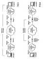
- FIG. 3is a schematic diagram of data crossing data networks from a first computer to a second computer wherein the two computers implement a secure end-to-end data connection using IPsec according to one embodiment
- FIG. 4is a schematic diagram of data crossing data networks from a first computer to a second computer wherein two security gateways implement a secure data connection across the untrusted portion of the network using IPsec according to one embodiment
- FIG. 5is a schematic diagram of data crossing data networks from a laptop computer to an office computer wherein the laptop computer and a security gateway implement a secure data connection across the untrusted portion of the network using IPsec according to one embodiment
- FIG. 6is a schematic diagram of a possible provisioning system according to one embodiment
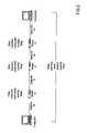
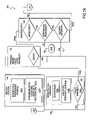
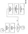
- FIGS. 7A and 7Bare flow diagrams illustrating a possible method for configuring a network to provide data connections according to one embodiment
- FIG. 8is a schematic diagram of a simple example wide area network connecting two local area networks according to one embodiment
- FIG. 9is a graph diagram representing the network of FIG. 8 according to one embodiment.
- FIG. 10is the graph diagram of FIG. 9 annotated to include bandwidths for the links in the graph according to one embodiment
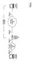
- FIG. 11is a schematic diagram of a candidate path traversing a network according to one embodiment.
- FIG. 12is a schematic diagram of a possible network topology according to one embodiment.
- both carriers and ASPswish to be able to package their services for convenient usage.
- access to the serviceis restricted to paying customers.
- the networkby way of which the services are provided in one embodiment provides QoS, security and data collection services so that the services are performed in a way which meets or exceeds customer expectations.
- QoS servicesare provided so that each user of the service is guaranteed a high quality experience, so that users can justify the money they are expending on the service; so that sufficient network bandwidth is provided to transfer the expected amount of user data in a timely manner; so that highly interactive applications transfer data with low delay and small variations in delay (i.e. jitter); and so that data transfer is reliable to accommodate application protocols that do not have built-in error detection and retransmission, or to avoid high delays due to excessive retransmission.
- securityis provided so that if sensitive business information is involved, users have assurances that their information will be kept private; that communicating entities are authenticated to prove their identifies; and that communicated data is authenticated to ensure that it has not been modified in transit.
- data collectionis provided to allow the carriers and ASPs to collect detailed usage data so that bills are generated; so that actual bandwidth consumed is measured; so that network delays and jitter are recorded; so that the amount of data communicated or the duration over which it is communicated is measured; and, so that data is collected about individual instances of service usage.
- Embodiments of this inventioncan be applied to many different types of packet data communication network.
- IPInternet Protocol
- Embodiments of this inventioncan be applied to many different types of packet data communication network.
- the following descriptiondiscusses the application of one embodiment to a network using the Internet Protocol (IP) (e.g. the Internet), but this and other embodiments are not limited to being used in IP networks.
- IPInternet Protocol
- One embodimenthas several aspects.
- One aspectrelates to automatically selecting a path to be taken by data packets through a packet data network in such a manner that the routers or other network devices in the path have the capabilities to provide desired levels of QoS, security and/or data collection.
- Another aspectrelates to configuring routers or other network devices on a selected path to provide desired levels of QoS, security and/or data collection in respect of data packets traversing the path. The capabilities of individual routers are taken into consideration.
- FIG. 1is a schematic diagram of a simple example wide area network connecting two local area networks according to one embodiment. It shows a network which illustrates some of the difficulties addressed by one embodiment.
- Computers 1 , 2 , 3 , and 4are inter-connected to each other and router 10 by LAN 20 .
- computers 5 , 6 , 7 , and 8are inter-connected to each other and router 14 by LAN 21 .
- the two LANs and their attached computersare in one embodiment two sites belonging to the same corporation.
- LAN 20 and its computers in one embodimentbelong to a corporation while LAN 21 and its computers in one embodiment belong to an ASP.
- WAN 40comprises routers 11 , 12 , and 13 .
- WAN 40also includes data links 30 , 31 , 32 , 33 , 34 , and 35 .
- Routers 10 and 14are according to one embodiment considered to belong to LANs 20 and 21 , since these are access routers that connect LANs 20 and 21 respectively to WAN 40 .
- the routersare typically configured to forward packets via the shortest path between the source computer and the destination computer.
- the routersare typically configured to forward packets via the shortest path between the source computer and the destination computer.
- This pathextends from computer 3 to computer 6 by way of: LAN 20 , router 10 , data link 31 , router 12 , data link 34 , router 14 , and LAN 21 .
- Some modern routerssupport additional QoS-enhanced forwarding mechanisms. Typically these routers perform FIFO routing by default. QoS-enhanced forwarding is only performed if a user explicitly configures the router to perform QoS-enhanced forwarding. Some types of QoS-enhanced forwarding allow certain packets to be directed out a selected output port of a router. If routers 10 , 11 , 13 , and 14 support QoS-enhanced forwarding mechanisms, it is in one embodiment possible to configure these routers so that packets being sent from computer 3 to computer 6 follow a different path.
- the packetsare in one embodiment sent along a path extending from computer 3 through LAN 20 , router 10 , data link 30 , router 11 , data link 33 , router 13 , data link 35 , router 14 , LAN 21 , and finally to computer 6 .
- the communication between computers 3 and 6 in FIG. 1is associated with a service based on a point-to-point client/server application.
- computer 6is the server. It is possible that the computers 1 , 2 , and 4 in one embodiment are also using the service (i.e. a client/server application) at the same time as computer 3 .
- the packets flowing between the computers on LAN 20 and computer 6will follow the same path through the network. This is an example of “concurrent service usage” between the computers of LAN 20 and computer 6 .
- Each routerhas a number of output ports. Each output port connects to a data link. When a packet is received at a router the router reads the packet's destination, determines the appropriate output port and queues the packet at the selected output port to wait for its turn to be transmitted on the data link attached to the output port. In the case of FIFO routing, the queued packets are transmitted in the order in which they were queued. Each type of QoS-enhanced forwarding mechanism has its own unique scheduling algorithm that determines the order in which queued packets are transmitted.
- Each data linkhas a bandwidth which in one embodiment is measured in units of bits per second.
- the bandwidthis in one embodiment fixed, and in an alternative embodiment, it varies.
- a T3 facility used as a single IP data linkin one embodiment provides a fixed bandwidth of approximately 45 Mbps.
- the same T3 facilityis in one embodiment also configured with IP protocol running on top of ATM running on top of the T3.
- IP protocolrunning on top of ATM running on top of the T3.
- ATMallows the T3 facility to be segregated into multiple virtual circuits.
- each of the virtual circuitsappears to be a separate data link.
- the bandwidth of a data link running on top of an ATM virtual circuitis in one embodiment fixed, and in an alternative embodiment variable, depending on the ATM virtual circuit's class of service.
- the bandwidth of a data linkis a resource that is available to be allocated for use by services. For example, in one embodiment it is decided to allocate a 10 Mbps data link to three services.
- the first serviceis in one embodiment allocated 5 Mbps
- the second serviceis in one embodiment allocated 2 Mbps
- the third serviceis in one embodiment allocated 3 Mbps.
- bandwidth on a data linkThere are two types of bandwidth on a data link that are in one embodiment allocated to a service.
- the first type of bandwidthis minimum bandwidth.
- a serviceis guaranteed that its minimum bandwidth will be available. For example, by allocating a 1 Mbps minimum bandwidth to a service, the service is guaranteed that there will be at least 1 Mbps of bandwidth available for its use.
- the second type of bandwidthis maximum bandwidth.
- a serviceis not permitted to consume more than its maximum bandwidth. For example, by allocating a 2 Mbps maximum bandwidth to a service, the service will not be permitted to use more than 2 Mbps of bandwidth.
- the packetwill experience transmission delays getting out of a router due to the fixed bandwidth of the data link. It will experience signal propagation delays due to the finite speed of signals on a data link. It will experience processing delays in routers when the router first receives it and while the packet is being prepared for transmission once it has been selected as the next packet to be transmitted. It will also experience queuing delays while it is queued in a router waiting to be selected for transmission.
- queuing delaysare the largest source of delay. If a packet experiences significant delay as it is forwarded across a typical network, most of the delay will be queuing delays. Transmission, propagation, and processing delays typically represent only a small percentage of the overall delay.
- Some types of QoS-enhanced forwarding mechanismin one embodiment control queuing delay within a router.
- the QoS-enhanced forwarding mechanismin one embodiment ensures that packets associated with the service experience low delays. If this expedited forwarding is performed consistently across the network, the overall delay experienced by packets associated with the service is in one embodiment managed to a selected value even if other packets experience longer delays in traversing the network.
- a network in one embodimentincludes many different types of routers each having different capabilities. For certain services, it is in one embodiment desirable to control the maximum cross-network delay. Since transmission, propagation, and processing delays are fixed values for a given path through the network, subtracting the various transmission, propagation, and processing delays from the maximum cross-network delay is in one embodiment used to calculate the maximum cross-network queuing delay. In preferred embodiments, portions of the maximum cross-network queuing delay are allocated to each router along the path as a maximum cross-router queuing delay. Where a certain router on the path only loosely controls cross-router queuing delay, that router is in one embodiment allocated a larger portion of the maximum cross-network queuing delay. A router that expedites packets and tightly controls delay is in one embodiment allocated a smaller portion of the maximum cross-network queuing delay.
- FIG. 2is a schematic diagram of data crossing a network from a first computer to a second computer illustrating a cross-network queuing delay according to one embodiment.
- This pathconnects computer 1 to computer 2 . It includes data link 20 , router 10 , data link 21 , router 11 , data link 22 , router 12 , and data link 23 .
- the maximum allowable cross-network delayis in one embodiment set at 65 ms. Once transmission, propagation, and processing delays have been subtracted, the maximum cross-network queuing delay is in one embodiment found to be 60 ms. In the example shown in FIG. 2 , 10 ms. of the 60 ms.
- Router 10has been allocated to router 10 as its maximum cross-router queuing delay.
- Router 11has been allocated 30 ms. of the 60 ms. as its maximum cross-router queuing delay.
- Router 12has been allocated the remaining 20 ms. of the 60 ms. as its maximum cross-router queuing delay.
- a maximum cross-router queuing delay for packets in a serviceis in one embodiment set if a maximum bandwidth for the service is also set.
- Jitteris a measure of the variation in delay. For example, if the packets associated with a service experience cross-network delays ranging between 40 and 60 ms., the packets are experiencing 20 ms. (60 ms.–40 ms.) of jitter.
- Some types of QoS-enhanced forwarding mechanismcontrol jitter. If the forwarding mechanism manages the queuing delay within the router, so that each packet associated with a service experiences the same queuing delay, the jitter will be zero. If jitter management is performed consistently across the network, the overall jitter experienced by the packets associated with a service is in one embodiment managed to a specific value.
- maximum cross-network jitterFor certain services, it is in one embodiment desirable to control the maximum cross-network jitter. Since transmission, propagation, and processing delays are consistent, they introduce only small amounts of jitter. The variation in cross-network queuing delay largely determines the cross-network jitter, so maximum cross-network jitter is in one embodiment considered to be equivalent to the maximum cross-network queuing jitter. Portions of the maximum cross-network queuing jitter are in one embodiment allocated to each router along the path as a maximum cross-router queuing jitter. As with delay, a greater or lesser portion of the maximum cross-network queuing jitter is in one embodiment allocated to individual routers to accommodate their varying abilities to manage jitter.
- a packetAs a packet is forwarded across the network, it in one embodiment gets lost and does not reach its destination for any of a variety of reasons.
- a router in one embodimenthas a design flaw that causes packets to be lost. By far the most common cause of packet loss is packet discard associated with congestion. When a router gets congested (i.e. it is receiving more packets than it can transmit), its queues will fill up. At some point the router is forced to discard packets. If the packets associated with a service can be exempted from being discarded in congestion situations, it is possible to control the packet loss rate experienced by a service.
- the concept of reliabilityis in one embodiment introduced. If a service is required to have a reliability of 99% then only 1% of its packets are allowed to be lost. Where only one attempt is made to send a given packet from the source computer to the destination computer, this concept makes sense.
- a protocole.g. TCP
- TCPkeeps track of sent packets, returns acknowledgements for successfully received packets, and retransmits lost packets, it is not clear what reliability means, because each packet will probably get through eventually even if it is discarded 1000 times before it is successful.
- the concept of reliabilityis in one embodiment extended. If a service is required to have a reliability of 99%, a maximum of 1% of its packets will in one embodiment over require a retransmission because the first copy of the packet was lost.
- a service in one embodimentrequires that data communication be secured in transit across an untrusted portion of the network. This is in one embodiment accomplished by creating a secure communication channel through the untrusted part of the network by applying authentication and encryption to data packets. The end points of the secure communication channel are in one embodiment required to authenticate themselves to each other, so both parties in one embodiment are certain they are communicating with a trusted party.
- a security policyis in one embodiment defined for each service that specifies exactly how authentication and encryption are to be performed. Since the security policy applies to all instances of the service, it in one embodiment does not specify locations in the network where security is in one embodiment applied and removed.
- IPsecis a security technology that is in one embodiment used to secure IP protocol data communication.
- IPsecsupports various algorithms (e.g. DES, Triple DES, Blowfish) for encryption of data packets.
- algorithmse.g. MD5, SHA
- MD5, SHAare supported for authenticating that packets have not been modified in transit.
- schemese.g. pre-shared keys, public keys, and certificates
- IPsecis in alternative embodiments used in a variety of configurations.
- Two computers in one embodimentuse IPsec end-to-end to secure their communication.
- FIG. 3is a schematic diagram of data crossing data networks from a first computer to a second computer wherein the two computers implement a secure end-to-end data connection using IPsec according to one embodiment. If the two computers are located on corporate LANs, there is in one embodiment a router acting as a security gateway at the boundary between the trusted LAN and the untrusted WAN. Secure communication is in one embodiment established between two such security gateways.
- FIG. 4is a schematic diagram of data crossing data networks from a first computer to a second computer wherein two security gateways implement a secure data connection across the untrusted portion of the network using IPsec according to one embodiment.
- FIG. 5is a schematic diagram of data crossing data networks from a laptop computer to an office computer wherein the laptop computer and a security gateway implement a secure data connection across the untrusted portion of the network using IPsec according to one embodiment.
- SSLSecure Sockets Layer
- Other technologiessuch as Secure Sockets Layer (“SSL”) provide in one embodiment similar features for IP protocol based networks.
- SSLSecure Sockets Layer
- Other security technologiesare in one embodiment applied to non-IP networks.
- a servicerequires secure communication, it is desirable to select a configuration, identify the computers or routers between which secure communication will be implemented, and configure the computers or routers with matching sets of parameters (e.g. algorithm choices, key lifetimes) that control how the security will be provided.
- parameterse.g. algorithm choices, key lifetimes
- a first considerationis granularity.
- Routers in one embodimentcollect data about all the packets passing through an input or output interface.
- Routers in one embodimentcollect data about individual categories of packets passing through the interface.
- Routers in one embodimentcollect data about individual packet flows corresponding to individual users and their applications.
- Routers in one embodimentcount packets and keep track of time in order to measure actual bandwidth to varying degrees of temporal granularity. Routers in one embodiment measure cross-router delay and jitter or contribute to cross-network delay and jitter measurement. Routers in one embodiment count discarded packets and keep track of time in order to measure reliability. Routers in one embodiment measure service usage. One type of service usage measurement requires the counting of individual packet flows. Another records the source, the destination, the start date and time, and the end date and time of each packet flow.
- a third considerationis the degree to which data collection is targeted at individual selected packet flows.
- Routersin one embodiment support the collection of very detailed data, but collection is in one embodiment performed on all of the packet flows passing through an input or output interface. This in one embodiment results in a torrent of data being collected when only a trickle was desired.
- a service in one embodimentrequires that an SLA be managed, and in an alternative embodiment, it is billed according to usage.
- the above types of data collectionare performed.
- an appropriate routeris selected through which data packets associated with the service will flow and that is capable of performing the required data collection. In a preferred embodiment, this router collects just the desirable data without generating large amounts of uncalled-for data as a by-product.
- an initial activity in provisioning a serviceis to accept as input a detailed description of the service.
- the descriptionspecifies the requirements that are in one embodiment to be satisfied by the provisioning process.
- the service descriptionin one embodiment, for example, identifies:
- a network location of a party involved in a service provided on an IP networkis in one embodiment expressed as an IP address, a set of IP addresses, a range of IP addresses, or an IP subnet. Where the network location of a party is multiple IP addresses, the party in one embodiment uses the service from a computer at any of those addresses. In an alternative embodiment, any one of these locations is expressed as a fully qualified domain name.
- a security profilespecifies a set of parameters that determine the exact nature of the security to be provided to a data connection.
- the parametersin one embodiment identify encryption algorithms, authentication algorithms, key lifetimes, how parties are to be authenticated, how public keys are generated, etc.
- the types of parametersare in one embodiment determined by the security technology being used.
- the information in one embodimentis organized in different groupings than indicated.
- the informationis in one embodiment stored in binary form.
- the informationis stored in textual form.
- the information in one embodimentis expressed using the XML language.
- the informationis in one embodiment stored in text files.
- the informationis stored in binary files.
- the informationis stored in databases.
- provisioningensures that the path followed by a data connection passes through routers that are configured to provide the specified QoS, provide the specified security, and perform the specified data collection. Where possible, provisioning will attempt to influence the path taken by data connections to ensure that the path passes through routers with adequate capabilities. Provisioning will configure the routers along the path to meet the specified requirements for the data connection.
- the combination of the path followed by a data connection from a source to a destination and the configuration that is performed on routers along this pathare in one embodiment referred to as a data connection channel.
- the data connection channelstarts at the router closest to the source and ends at the router closest to the destination.
- a data connection channelis in one embodiment a uni-directional pipe through the network in which one or more data connections of the same type are carried. Multiple data connections occur when the service is used multiple times concurrently between the same source and destination routers. Two-way data connections will be carried in two data connection channels having opposite directions to each other.
- the goal of provisioningis to deploy data connection channels.
- the endpoints of a data connection channelare specified by the service description.
- the characteristics of the data connection channelare described by the corresponding data connection description in the service description.
- Each data connection description describing a one-way data connectionwill result in one data connection channel being provisioned.
- Each data connection description describing a two-way data connectionwill result in two data connection channels being provisioned.
- FIG. 6is a schematic diagram of a possible provisioning system 64 according to one embodiment.
- Provisioning system 64uses the service description and data connection descriptions to identify data connection channels.
- Provisioning system 64preferably comprises a programmed provisioning engine 66 .
- provisioning engine 66is a network controller computer.
- Provisioning system 64performs a separate provisioning activity for each data connection channel. These provisioning activities are in one embodiment performed consecutively or concurrently. If any one of these provisioning activities fails, overall provisioning of the service is considered to have failed, and any data connection channels which belong to the service and have already been successfully provisioned are removed.
- Network topology database 60contains information regarding all of the routers in a managed network 61 , the interfaces on those routers, and the data links that connect interfaces of different routers together.
- Network topology database 60preferably records:
- Routing tablesare normally associated with FIFO forwarding, but they are also used by some QoS-enhanced forwarding mechanisms. Routing tables are maintained by routing protocols (e.g. Routing Information Protocol (“RIP”), Open Shortest Path First (“OSPF”), Border Gateway Protocol (“BGP”), etc.) that exchange information about network topology between routers. Routing tables normally only consider the destination of the packet in determining where a packet is to be sent. Other QoS-enhanced forwarding mechanisms maintain their own tables that govern where packets are sent. For example, one QoS-enhanced forwarding mechanism uses policies.
- routing protocolse.g. Routing Information Protocol (“RIP”), Open Shortest Path First (“OSPF”), Border Gateway Protocol (“BGP”), etc.
- OSPFOpen Shortest Path First
- BGPBorder Gateway Protocol
- Routing tablesnormally only consider the destination of the packet in determining where a packet is to be sent.
- Other QoS-enhanced forwarding mechanismsmaintain their own tables that govern where packets are sent.
- a policydefines rules that classifies packets into classes on the basis of some combination of source IP address, destination IP address, source TCP/UDP port, destination TCP/UDP port, protocol, type of service, arrival interface, TCP acknowledgement flag, date, and time.
- the policyspecifies where packets that are classified into each class are to be sent.
- network topology database 60may in one embodiment contain all the information needed to calculate routing tables for routers on network 61
- network topology database 60in a preferred embodiment retrieves and records copies of the routing tables from each of the routers. The reason for this is that various router vendors use slightly different algorithms to generate routing tables which provide the “best” routes to given destinations. Calculations performed from information in network topology database 60 will not necessarily generate routing tables identical to the routing tables in each router. This is especially true in situations where there are multiple alternative equal-length paths to a destination.
- Network topology database 60in one embodiment contains information specifying where the routers will actually send a packet rather than potentially faulty predictions about where the routers will send the packet.
- the routers used in networkstypically include a management interface which permits the router to be remotely configured and which permits management information (which in one embodiment includes the current configuration of the router, acquired data about traffic through the router, error logs, routing tables, etc.) to be requested and received at a remote location.
- management informationwhich in one embodiment includes the current configuration of the router, acquired data about traffic through the router, error logs, routing tables, etc.
- network topology database 60is constructed by remotely querying each router in network 61 for topology information using the management interface. Topology information is acquired when provisioning system 64 is first started and thereafter on a periodic basis to ensure the information in network topology database 60 remains up to date.
- the dataare in one embodiment stored in binary form.
- the dataare in an alternative embodiment stored in text form.
- the dataare in one embodiment stored in text files, in an alternative embodiment in binary files, and in yet another alternative embodiment, in databases.
- Provisioned service database 62preferably records:
- the dataare in one embodiment stored in binary form.
- the dataare in an alternative embodiment stored in text form.
- the dataare in one embodiment stored in text files, in an alternative embodiment in binary files, and in yet another alternative embodiment, in databases.
- Network topology database 60records the available bandwidth on each data link in network 61 .
- Provisioned service database 62records the minimum bandwidth committed to each data connection channel. By adding together the bandwidth commitments made to data connection channels deployed on a given data link (from provisioned services database 62 ), provisioning system 64 in one embodiment determines how much, if any, of a data link's bandwidth capacity is still available for allocation to additional services.
- Provisioning system 64uses information in network topology database 60 and the provisioned services database 62 to provision new data connections. Provisioning system 64 in one embodiment allows a percentage of the bandwidth to be reserved separately for each direction of each data link. This reserve is useful because it:
- FIGS. 7A and 7Bare flow diagrams illustrating a possible method for configuring a network to provide data connections according to one embodiment.
- FIGS. 7A and 7Bdepict a method 100 for provisioning a data channel according to one embodiment.
- Method 100is typically performed by a provisioning system 64 .
- Method 100begins by identifying the routers at the source and destination of the data connection channel (process block 104 ).
- Process block 104 Acomprises reading relevant portions of the service description and the relevant data connection description when a service is being initially provisioned or an existing service is being re-provisioned.
- the provisioning systemin one embodiment uses this information to identify the parties at both endpoints of the data connection channel and the network locations of the parties. If necessary, the network locations in one embodiment are translated from a fully qualified domain name to a numeric IP address or IP subnet using a Domain Name Service (“DNS”) associated with the network.
- DNSDomain Name Service
- the IP address or IP subnet of the network locationis compared to the IP subnet of each router interface in network topology database 60 (process block 104 B). If the IP address of the network location belongs to the IP subnet of a router interface, the corresponding router and interface is selected as a possible data connection channel endpoint. If the IP subnet of the network location is identical to the IP subnet of a router interface, the corresponding router and interface is selected as a possible data connection channel endpoint. The result of the comparison will be a set of one or more routers that in one embodiment act as the endpoint of the data connection channel. Process block 104 generates for each of the two endpoints of a data connection channel a set of one or more routers.
- FIG. 8is a schematic diagram of a simple example wide area network connecting two local area networks according to one embodiment. It is an example of source and destination router identification.
- LAN 20i.e. IP subnet 20
- LAN 21i.e. IP subnet 21
- Identification of endpoint routerswill determine that routers 10 and 11 are connected to IP subnet 20 and are possible endpoints at the source of the data connection channel. It will also be determined that routers 15 , 16 , and 17 are connected to IP subnet 21 and are possible endpoints at the destination of the data connection channel.
- FIG. 8also illustrates concurrent usage of a service.
- LAN 20in one embodiment is resident at a corporate branch office.
- LAN 21in one embodiment is resident at a corporate head office.
- the service descriptionin one embodiment indicates that there can be up to 3 concurrent users of the service.
- the service description and data connection descriptionin one embodiment indicate a single two-way data connection is required to use the service. As will be seen below, this will lead to the provisioning of two uni-directional data connection channels in opposite directions between either router 10 or 11 at one end and one of routers 15 , 16 , or 17 at the other end.
- the data connection channelWhen the data connection channel is deployed, it is in one embodiment deployed so that the various requirements of the data channel (e.g. bandwidth) are scaled to handle 3 data connections being carried by the data connection channel.
- Method 100continues by generating a path candidate extending between the source and destination endpoint routers (process block 108 ). For each endpoint where multiple routers were identified as a possible endpoint in process block 104 , one of the routers is selected to use as an endpoint for the first attempt to generate an acceptable path candidate. Other ones of the routers are in one embodiment used in subsequent attempts.
- the provisioning engine 66uses information from network topology database 60 to create a graph representing the network (process block 108 A).
- the graphis constructed such that vertices represent routers and links represent data links. Links in the graph have a directionality that indicates a direction in which packets in one embodiment flow on the corresponding data link.
- Two-way data linksare, according to one embodiment, represented in the graph by a bi-directional link or, according to another embodiment, as two back-to-back uni-directional links directed in opposite directions.
- FIG. 9is a graph diagram representing the network of FIG. 8 according to one embodiment.
- router 10has been selected as the source router and router 17 has been selected as the destination router.
- Provisioning engine 66applies a path identification algorithm to the graph (process block 108 B) to identify a path candidate extending from the source router to the destination router.
- Various path identification algorithmsare known to those skilled in the art.
- a suitable path identification algorithmis in one embodiment capable of identifying a path between two points in a network graph.
- a suitable algorithmis in one embodiment able to ensure compatibility between the directionality of the data connection channel and the considered links in the graph.
- Various path identification algorithmsare used in various embodiments. For example, there are a number of well-known path identification algorithms (e.g. Dijkstra's Shortest Path First algorithm)(“SPF algorithm”) that are suitable for path identification in alternative embodiments.
- SPF algorithmDijkstra's Shortest Path First algorithm
- Some of the techniques used by such algorithmsinclude graph traversal, heuristics, genetic selection, and stochastic annealing.
- path identificationtakes into account to the extent possible the QoS, security, and data collection requirements of the data connection channel. Of those requirements only minimum bandwidth should be satisfied by every data link on the path. In alternative embodiments, maximum bandwidth, security, and data collection requirements need only be satisfied at one or possibly two routers along the path, so satisfaction of these requirements are in one embodiment validated after a possible path has been identified. Maximum delay, maximum jitter, and minimum reliability are apportioned to all of the routers along a path, so satisfaction of these requirements is in one embodiment validated after a possible path has been identified.
- the path candidateis checked (process block 108 C) to determine whether the path candidate provides at least the minimum bandwidth required by the service being deployed. For a path candidate to supply the required minimum bandwidth, every data link in the path candidate has in one embodiment an available bandwidth equal to or greater than the minimum bandwidth of the data connection channel. If any data link in the path candidate does not have an available bandwidth greater or equal to the minimum bandwidth then the path candidate is in one embodiment removed from further consideration.
- the minimum bandwidth of the data connection channelwill be the minimum bandwidth from the data connection description multiplied by the maximum amount of concurrent service usage from the service description.
- An implied requirement of a data connection channelis reachability. In other words it is in one embodiment possible to reach the destination router from the source router using every data link along the path. If a router will not allow packets destined for the destination party to be sent out a specific data link, there is no need to consider that data link during path identification.
- the data linkis in one embodiment used to reach the destination party if the routing table indicates that the best route to the destination is via that link. If a router uses on the interface feeding a data link a QoS-enhanced forwarding mechanism that does not use routing tables, the data link is in one embodiment used to reach the destination party if the QoS-enhanced forwarding mechanism can be configured to direct packets to the destination party via that link.
- Some path identification algorithmsassociate weights with links. They use the weights to find the minimum or maximum aggregate weighted path through the graph.
- Dijkstra's SPF algorithm(see: E. W. Dijkstra, “A Note on Two Problems in Connection with Graphs”, Numewitz Mathematic, vol. 1, pp. 269–271, 1959) is an example of such an algorithm that finds the minimum aggregate weighted path.
- a path identification algorithm in one embodimenttakes into account minimum bandwidth and reachability.
- a first methodis to prune the graph while it is being constructed to remove links corresponding to data links that do not satisfy the minimum bandwidth and reachability criteria.
- a second methodis in one embodiment used with path identification algorithms that use link weighting.
- the path identification algorithmin one embodiment sets the weight allocated to each link in a manner which takes into account whether or not the link provides the minimum bandwidth and whether or not the link is reachable.
- This weightingis in one embodiment performed dynamically.
- the weightsare allocated in such a manner that links corresponding to data links that do not satisfy the minimum bandwidth and reachability criteria are not considered.
- Dijkstra's SPF algorithmis used to find the candidate path of minimum aggregate weight between the source and destination routers.
- Link weightsare calculated such that links with inadequate available bandwidth to satisfy the minimum bandwidth criteria are assigned a very large or infinite weight. Links which cannot possibly be used to reach the destination (for example because they are connected to a router which will not direct the data packets in question onto the link), are similarly assigned a very large or infinite weight.
- the weighting scheme used by Dijkstra's algorithmis a simple integer numerical weight assigned to each link in the graph. Dijkstra's algorithm looks for the lowest aggregate weight. For example, for a path having three links with weights of 3, 7, and 1 the aggregate weight is 11 (i.e. 3+7+1). One embodiment starts with a small weight of, for example, 1 for each link. This weight assumes that the link is suitable for use in reaching the destination. If evaluation concludes the link cannot be used to reach the destination (e.g. no reachability due to routing table entries refusing to direct packets destined for the destination out the corresponding data link), provisioning engine 66 changes the weight of the link to a large number or infinity.
- provisioning engine 66changes the weight of the link to a large number or infinity. It is noted that infinity is not easily represented as an integer, so in one embodiment a large weight, such as a large integer value, is assigned to links that are unsuitable for use.
- the weights assigned to data linksare used to express a preference or strategy for using links in certain parts of a network. For example, candidate paths are in one embodiment preferred which do not pass through the core network. Instead, links passing through a metro network are preferred unless it is absolutely necessary to reach the destination via the core network.
- provisioning system 64is biased against paths which pass through the core network by assigning a higher default weight to all core network data links. The higher the default weight, the stronger is the bias to avoid paths which extend through the core network. Similarly, in one embodiment provisioning system 64 is biased in favour of paths which pass through a core network by assigning a lower default weight to core network data links.
- the default weight to be assigned to linksis configurable to allow carriers to implement a deployment strategy.
- provisioning system 64varies the weights assigned to links as a function of the bandwidth that has been previously committed on the links. This permits path identification algorithms to be biased in favor of using links which are under-utilized. This in one embodiment is achieved, for example, by computing a usage fraction by dividing the aggregate bandwidth that has been previously allocated to data connection channels on a data link by the total unreserved bandwidth of the link. Provisioning system 64 in one embodiment reads the total unreserved bandwidth of a link from network topology database 60 and in one embodiment determines how much bandwidth on a link has been previously allocated to provisioned services from information in provisioned services database 62 .
- a weighting adjustment factoris in one embodiment applied depending upon which of a number of ranges the usage fraction falls into. In one embodiment there are five statuses and associated default percent usage ranges as shown in Table I.
- each status categoryPreferably the range of usage fractions in each status category are configurable.
- a link weight adjustmentexists for each usage fraction status category. This link weight adjustment is added to the link weight based on the current percent usage of a data link being considered. Accordingly, data links which are loaded relatively lightly are given preference.
- the link weight adjustmentsare preferably configurable. A carrier might use the above strategy to improve the customer's experience with the service by trying to leave uncommitted bandwidth on links as long as possible to handle unforeseen traffic patterns.
- linksare not penalized until the percent usage hits 75%.
- a userin one embodiment chooses to more strongly bias the route selection algorithm toward lightly loaded links. This is in one embodiment achieved, for example, by reconfiguring the link weight adjustments as shown in Table II.
- higher weightsare in one embodiment assigned to lesser utilized links. This in one embodiment will bias the route selection algorithm toward filling existing links before using empty links. A carrier might choose this strategy to defer capital expenditures on new links.
- FIG. 10is the graph diagram of FIG. 9 annotated to include bandwidths for the links in the graph according to one embodiment.
- the data connection channel being provisionedrequires 90 kbps (30 kbps per data connection multiplied by a maximum of 3 concurrent uses of the service).
- router 10is the source router and router 17 is the destination router.
- a pathis in one embodiment found between these two routers.
- the pathhas in one embodiment 90 kbps of available bandwidth.
- the obvious shortest pathis in one embodiment link 31 followed by link 38 , but link 31 only has 70 kbps of available bandwidth.
- Dijkstra's SPF algorithmwill in one embodiment actually find the best path to be that consisting of link 30 , link 34 , and link 38 .
- a path via routers 14 and 16will in one embodiment not be selected, because it is longer than the “best” path.
- Process block 108is repeated (as indicated at 109 ) until a path candidate which is capable of providing the required minimum bandwidth is identified. After a path candidate has been found to be capable of providing the required minimum bandwidth, method 100 continues to validate the candidate path to determine whether it can meet any QoS requirements for the data connection channel (process block 110 ).
- the maximum bandwidth requirement of the data connection channelis the maximum bandwidth from the data connection description multiplied by the maximum amount of concurrent service usage from the service description.
- the maximum bandwidth requirement of the data connection channelis automatically satisfied if the maximum bandwidth is specified as being “uncontrolled”. Otherwise the requirement is in one embodiment satisfied in one of two ways by a candidate path. If there is a data link on the path that has no bandwidth reserved, and whose total bandwidth is less than the maximum bandwidth requirement, then the requirement has been met. Otherwise if there is a router on the path that can be configured to enforce a maximum bandwidth constraint on an individual data connection then the maximum bandwidth constraint is satisfied.
- the delay requirements of the data connection channelare automatically satisfied if the maximum delay is specified as being “uncontrolled”. Otherwise a delay budget is created.
- Transmission, propagation, and processing delaysare estimated from information in the network topology database and summed over all data links and routers in the candidate path under consideration. It should be noted that the topology database would in one embodiment be required to contain the physical length of each data link in order to accurately calculate the propagation delay.
- the estimated total transmission, propagation, and processing delaysare subtracted from the maximum delay. The remaining delay is the maximum cross-network queuing delay.
- the maximum cross-network queuing delayis split up and allocated to each router as a maximum cross-router queuing delay.
- a routeris using a QoS-enhanced forwarding mechanism on the output interface being used in the candidate path and is capable of managing the maximum cross-router queuing delay of an individual data connection to a numerical limit
- the routeris in one embodiment assigned the smallest maximum cross-router queuing delay that the router is capable of managing according to the best practices guidelines of the router vendor. Reallocation of the maximum cross-network queuing delay as maximum cross-router queuing delays in the various routers on the path in one embodiment makes all the maximum cross-router queuing delays fit within the maximum cross-network queuing delay.
- the maximum cross-router queuing delay requirementis in one embodiment still met by over-provisioning the minimum bandwidth that the router guarantees to the data connection. This technique is in one embodiment used if the data connection description specifies a controlled maximum bandwidth.
- the maximum bandwidth termensures that the minimum egress bandwidth is at least equal to the maximum ingress bandwidth.
- S max /D maxensures that enough egress bandwidth is available to get a maximum sized packet out of the router within the required maximum cross-router queuing delay.
- the maximum packet sizeis in one embodiment the Maximum Transmission Unit (“MTU”) size for the outgoing data link.
- the MTUis a constant value for any given data link on current IP networks.
- the calculated over-provisioned minimum bandwidthis multiplied by the maximum amount of concurrent service usage from the service description and is allocated to the data connection channel as the revised minimum bandwidth of the data connection channel on the specific router being considered.
- the maximum cross-network queuing delayis in one embodiment reallocated as maximum cross-router queuing delays on individual routers, so the calculated over-provisioned minimum bandwidth in each router fits into the available bandwidth on that router.
- a routeris not capable of managing the maximum cross-router queuing delay to a numerical limit, or a maximum bandwidth is not specified for the service, or there is insufficient bandwidth available to allocate an over-provisioned bandwidth, or the achievable maximum cross-router queuing delays add up to a total larger than the maximum cross-network queuing delay, the candidate path is considered to have failed validation and is rejected.
- the jitter requirements of a data connection channelare automatically satisfied by any candidate path if the maximum jitter is specified as being “uncontrolled”. Otherwise a jitter budget is created.
- the maximum jitteris split up and allocated to each router as a maximum cross-router queuing jitter.
- a routeris using a QoS-enhanced forcing mechanism on the output interface and is capable of managing the maximum cross-router queuing jitter of an individual data connection to a numerical limit
- the routeris in one embodiment assigned the smallest maximum cross-router queuing jitter that the router is capable of managing according to the best practices guidelines of the router vendor. Reallocation of the maximum jitter as maximum cross-router queuing jitters in the various routers on the path in one embodiment makes all the maximum cross-router queuing jitters fit within the maximum jitter.
- a routerIf a router is not capable of managing the maximum cross-router queuing jitter to a numerical limit, or the achievable maximum cross-router queuing jitters add up to a total larger than the maximum jitter requirement for the data channel, the candidate path is considered to have failed validation and is rejected.
- the reliability requirements of the data connection channelare automatically satisfied if the reliability is specified as being “uncontrolled”. If the reliability is controlled, reliability requirements in one embodiment are satisfied if all of the following conditions are satisfied.
- Each router along the pathis in one embodiment capable of segregating the traffic associated with the service into a separate queue that is unaffected by other traffic.
- Each router along the pathdoes not in one embodiment randomly select packets for discard in congestion situations. In other words, each router does not in one embodiment use a packet discard method such as Random Early Discard (“RED”) or Weighted RED.
- REDRandom Early Discard
- Weighted REDWeighted RED.
- Each router along the pathhas in one embodiment sufficient available bandwidth to over-provision the minimum bandwidth for the data connection channel to be at least equal to the required maximum bandwidth from the data connection description.
- the minimum bandwidthis in one embodiment further over-provisioned to meet maximum cross-router queuing delay requirements as described above. If any of the above conditions is not met, the candidate path is considered to have failed validation and is rejected.
- method 100selects a new candidate path and attempts to validate the new candidate path as described above. This process is repeated until a candidate path is identified which does meet all QoS requirements specified for the data connection being provisioned.
- method 100continues by validating the candidate path to see if it meets any security requirements for the data connection channel being provisioned (process block 124 ). If no security is required for the data connection channel, the security requirements are automatically satisfied and method 100 proceeds to process block 125 . Otherwise validation proceeds as described below.
- IP subnetis dedicated to a customer it is in one embodiment assumed to be a subnet that is trusted by the customer.
- An IP subnet that is dedicated to a carrieris generally assumed to be a public subnet that is untrusted.
- Security gatewaysare in one embodiment found to protect any portion of a candidate path which passes through untrusted subnets.
- a party using a serviceis in one embodiment assumed to be associated with and belong to the security domain of the customer who subscribed to the service as indicated by the service description. The source and destination parties will probably be connected to the source and destination routers respectively by data links whose IP subnets are dedicated to the subscribing customer. This is in one embodiment determined by examining network topology database 60 of FIG. 6 . If so, validation continues as described starting in the next paragraph. If not, the parties are resident on the untrusted network or another customer's trusted network. No path through the network will satisfy the security requirements of the data connection channel. Service provisioning is deemed to have failed and is terminated as indicated at 119 of FIG. 7
- the provisioning engine 66follows the candidate path in the forward direction until the data link connecting the destination router to the destination party is reached.
- Network topology database 60 of FIG. 6is examined for each router to determine whether the router can act as a security gateway.
- Network topology database 60is examined for each data link to see whether the link is dedicated to the subscribing customer (and is therefore “trusted”).
- method 100 of FIG. 7Aattempts to locate a pair of routers capable of acting as security gateways in trusted portions of the candidate path that bracket any untrusted portions of the candidate path.
- FIG. 11is a schematic diagram of a candidate path traversing a network.
- the pathstarts at source party computer 1 and ends at destination party computer 2 according to one embodiment. In between it traverses in order trusted data link 20 , router 10 , untrusted data link 21 , router 11 , untrusted data link 22 , router 12 , trusted data link 23 , router 13 , trusted data link 24 , router 14 , untrusted data link 25 , router 15 , untrusted data link 26 , router 16 , and trusted data link 27 .
- a pair of security gatewaysin one embodiment bracket the sub-path consisting of untrusted data links 21 and 22 . Routers 10 and 12 are in the correct position to act as security gateways.
- routers 14 and 16are correctly positioned to bracket the sub-path consisting of untrusted data links 25 and 26 .
- Routers 10 and 16bracket both untrusted sub-paths (together with the trusted sub-path comprising data links 23 and 24 ). If routers 10 and 16 are capable of acting as security gateways, they in one embodiment protect most of the candidate path.
- pairs of security gatewaysare in one embodiment found to bracket all untrusted sub-paths in a candidate path then the candidate path is considered to have passed validation and method 100 of FIG. 7A proceeds to process block 125 . If no such pairs are found then the candidate path is rejected as indicated at 121 . Method 100 then repeats process block 108 to generate another candidate path.
- Process block 124 in one embodimentassumes that all security gateways fully implement the same security standard (e.g. IPsec) and are capable of implementing the security described in the security profile associated with the data connection description.
- IPsecsecurity standard
- Method 100continues at process block 127 to validate the candidate path identified for the data connection channel to see if it meets any data collection requirements of the data connection channel.
- the provisioning engine 66follows the candidate path in the forward direction until the destination router is reached.
- the provisioning enginechecks the record for each router in network topology database 60 of FIG. 6 to determine whether the router can satisfy any of the data connection channel's data collection requirements. If a combination of one or more routers are found along the candidate path which can collectively meet all data collection requirements for the channel then the data collection requirement is considered to have been satisfied. If the destination router is reached and there are any data collection requirements left that have not been satisfied, the path is considered to have failed validation. The path is rejected, and method of 100 of FIG. 7A returns to process block 108 to generate and attempt to validate another candidate path.
- a routersatisfies a data collection requirement if it collects or can be configured to collect the desired type of information at the desired granularity. If the data collection granularity is at the level of data connections then concurrent service usage is in one embodiment factored into the validation. Concurrent service usage will multiply the number of data connections for which data is in one embodiment collected.
- the pathis considered to have successfully passed all validation.
- the pathis deemed to be suitable for provisioning the data connection channel.
- Method 100continues at process block 130 by configuring the routers along the successfully validated candidate path to implement the QoS, security, and data collection requirements.
- a recordwas kept of the minimum bandwidth, maximum bandwidth, maximum cross-router delay, maximum cross-router jitter, and minimum reliability to be enforced at that router.
- a recordwas kept of the security functions, if any, to be performed by the router.
- a recordwas kept of the data collection, if any, to be performed by the router.
- the provisioning engine 66Starting at the source router, the provisioning engine 66 follows the path in the forward direction until the destination router is reached. At each router along the path the provisioning engine attempts to configure the router as to:
- a preferred embodimentis able to operate in a heterogeneous network consisting of routers from different vendors.
- Router configurationis vendor dependent.
- the provisioning engine 66maintains a translation module 70 ( FIG. 6 shows four translation modules 70 A, 70 B, 70 C, 70 D).
- Each translation module 70is capable of translating minimum bandwidths in bits per second, maximum bandwidths in bits per second, maximum cross-router delays in seconds, maximum cross-router jitter in seconds, and minimum reliability in percent to an appropriate set of management commands for that make and model of router.
- Provisioning engine 66identifies the make and model of each router in the path from information in network topology database 60 and selects the translation module 70 appropriate for that router.
- Provisioning engine 66then supplies the translation module 70 with the QoS, security and data collection properties which the router in one embodiment is to implement.
- Translation module 70translates the desired QoS, security, and data collection properties for that router into a set of commands which in one embodiment are effective to cause the router to implement enforcement of the applicable minimum bandwidth, maximum bandwidth, maximum cross-router delays, maximum cross-router jitter, and minimum reliability.
- Translation module 70is capable of translating the security functions described in the security profile to an appropriate set of management commands for that make and model of router to implement the described security.
- Translation module 70is capable of translating the data collection allocated to the router to an appropriate set of management commands for that make and model to enable the desired data collection, if necessary.
- Each translation module 70uses the appropriate access protocol (e.g., Telnet, Common Object Request Broker Architecture (“CORBA”), Simple Network Management Protocol (“SNMP”), etc.) to remotely access the router and issue the generated commands to provision the data connection channel.
- the configuration performed on the routeris recorded in provisioned services database 62 .
- the configuration information saved in the provisioned services database 62is vendor and possibly model specific.
- each routerIt is not necessary for the capabilities of each router to be recorded in network topology database 60 or in the provisioned services database 62 . Preferably the make and model of each router is recorded in network topology database 60 .
- This informationis used to identify the translation module 70 corresponding to each router.
- Each translation module 70is preferably capable of managing the corresponding router.
- the translation module 70translates a standard set of commands and queries into the vendor-specific commands and queries supported by the router.
- An example of such a standard queryis “are you capable of managing minimum bandwidth for a data connection channel?” This might be answered directly by the translation module since it may know the capabilities of each router model supported by the module.
- Another example of a standard commandis “Set the minimum bandwidth to 100 kbps.”
- the translation modulewould translate this into a vendor-specific command or commands for the supported model of router.
- a standard command or querydoes not translate into a capability of a vendor's router. If the capabilities of the router have been slightly misrepresented, this situation will be detected when the translation module 70 is asked to configure the router.
- the translation module 70in one embodiment rejects a configuration request that is incompatible with the router's capabilities. Such a rejection results in the path being rejected (process block 131 ). When this occurs, method 100 returns to process block 108 (process block 140 ) to make an attempt to find a different candidate path through the network.
- a routeris a security gateway, but it does not fully implement the IPsec standard. If a translation module 70 is asked to provision security functions (e.g. an encryption algorithm) which the router does not support, it will in one embodiment reject the configuration request.
- security functionse.g. an encryption algorithm
- the translation moduleuses provisioned services database 62 to identify the configuration that has been performed for a data connection channel. Provisioning engine 66 invokes the appropriate translation module(s) 70 to generate and issue management commands to remove the configuration.
- the service descriptionis recorded in the provisioned services database (process block 132 ). If not already done, the data connection description and security profile associated with the data connection channel are recorded in the provisioned services database (process block 134 ). The validated candidate path is recorded in the provisioned services database 62 (process block 136 ).
- provisioning system 64uses provisioned services database 62 to identify any data connection channels that have been provisioned to implement the service. For each data connection channel, the provisioned services database 62 is used to identify the path followed by the data connection channel and the configuration that has been performed at the routers along the path. Provisioning engine 66 then requests the configuration modules 70 for each router on the path to undo any configuration associated with the data connection channel from each router along the path. The entries in the provisioned services database 62 are then removed. In a preferred embodiment, the configurations of each router are not of a type such that changing a configuration for one provisioned service deleteriously affects the configuration for another provisioned service.
- a serviceis redeployed after the service description, the data connection descriptions, or the security profiles have been changed.
- provisioning system 64preferably first removes the service using the entries in the provisioned services database 62 as described above. The service is then provisioned again using the revised service description, data connection descriptions, and security profiles.
- Network topology database 60contains a copy of the routing table from each router.
- the entries in a router's routing tablein one embodiment change over time. Routing protocols are designed to be conservative in order to avoid a phenomenon called route flapping where a route in a routing table toggles continuously between two values. Most routers implement algorithms for updating routing tables which provide that a routing table entry will only be updated when a routing protocol is rather certain that the new route will last for a while.
- routing table changesin one embodiment cause packets associated with a service to be directed out a different interface of a router than predicted from the contents of network topology database 60 , in one embodiment, data connection channels passing through a router when a routing table entry has changed are re-evaluated.
- routing tablesare reacquired periodically from the router and compared against the old copy stored in network topology database 60 to identify routing table entries which have changed, if any.
- a routing table entryidentifies a destination IP subnet, an output interface (and hence an output data link), and the next hop router to which a packet destined for the destination IP subnet is in one embodiment forwarded.
- provisioning system 64uses provisioned services database 62 to identify any data connection channels provisioned on the data link connected to the router interface referenced by the old router table entry. For each identified data connection channel, the provisioned services database 62 is used to identify the destination IP address or IP subnet of the data connection channel.
- the data connection channelis deemed to be affected by the change in the routing table entry.
- provisioned services database 62is used to de-provision the data connection channel. The data connection channel is then re-provisioned.
- Provisioning system 64will not necessarily be able to control all routers in a network. Some portions of a network are in one embodiment not managed by provisioning system 64 but are managed by some other source. For example, it is unlikely that a corporation would allow a carrier provisioning system to manage their corporate LAN.
- the presence of a corporate LAN, customer network or other portion of the network which is not managed by provisioning system 64 in general,is in one embodiment identified via the detection of routers in the network that provisioning system 64 does not have in its topology database 60 or by the detection of IP subnets that are not directly connected to a router in network topology database 60 .
- Routers in the network topology database 60are considered to be managed routers whereas other routers are considered to be unmanaged routers.
- the router's routing tablewill contain entries for the interfaces connected to the customer network.
- the routing tablewill identify next hop routers that are not in network topology database 60 .
- the routing tablewill also indicate routes via these interfaces to IP subnets that are not directly connected to any managed router. These signs indicate the presence of a customer network.
- a carrier in one embodimentchooses not to manage (i.e. explicitly provision services to) its core network.
- the reason for thisis that many carriers use extremely fast dumb routers in the core of their networks. These routers in one embodiment only operate in FIFO routing mode, do not act as security gateways, and do not support data collection. They do have enormous capacity however.
- QoSis not an issue, because the core network data links and routers are upgraded frequently to ensure that they have more capacity than is needed. If a router and its data links have enough capacity to forward all traffic faster than it can accumulate then QoS issues disappear. There are no bandwidth, delay, jitter, or reliability issues.
- Routing tables in managed routerswill indicate the presence of routers that do not appear in the topology database and IP subnets that are not directly attached to a managed router.
- network cloudrepresents an unmanaged customer network or carrier core network.
- a network cloudaccording to one embodiment is represented as a new type of node in network topology database 60 . If a data link is determined to have unknown routers at the far end of the data link from a managed router then the data link connects the managed router to a network cloud node.
- Customer network cloudsare in one embodiment distinguished from unmanaged core network clouds by examining the data links connecting a managed router to a network cloud. If the data link is dedicated to a specific customer, the network cloud at the far end of the data link is in one embodiment attributed to that customer. If the data link is dedicated to the carrier, the network cloud at the far end of the data link is in one embodiment an unmanaged core network cloud.
- Customer network cloudstypically exist at the edge of the managed network and are accessed by one or a few managed routers. Their only significance to service provisioning is that any of the IP addresses or IP subnets in a customer network cloud in one embodiment serve as the endpoint of a data connection.
- the provisioning methodis in one embodiment able to identify a managed router as the endpoint of a data connection channel even when it is not directly connected to a source or destination IP address or IP subnet.
- FIG. 12is a schematic diagram of a possible network topology according to one embodiment.
- the carrierplaces most of its network in an unmanaged core network cloud.
- This core networkis over-provisioned and provides suitable QoS.
- Intelligenceexists in the access routers.
- the access routersmanage the QoS of low speed access links.
- the access routersact as security gateways.
- the access routerssupport detailed data collection.
- Service provisioningis performed across an unmanaged core network cloud by treating it like a single router that has many interfaces and data links connecting it to managed routers.
- path identificationdoes not consider the core network cloud's ability to meet the minimum bandwidth requirement.
- One potential problemis reachability.
- a data connectionwhen a data connection enters a core network cloud, it should be determined to where the packets will be routed (i.e. where they will emerge from the cloud).
- An answer to this problemis to determine experimentally how packets pass through the core network cloud by, for example, using the standard IP protocol utilities ping and traceroute.
- Pingis in one embodiment used to verify that a router is reachable.
- Tracerouteis in one embodiment used to identify the exact route followed by packets through a network to a specific router. Many routers support ping and traceroute as diagnostic utilities. These utilities are accessible via the management interfaces.
- Provisioning system 64in one embodiment invokes these or similar utilities to obtain and store in network topology database 60 information regarding the paths taken by packets through a core network cloud.
- translation modules 70provide generic access to these capabilities of each managed router in the network. If graph pruning is performed and a link feeding into a core network cloud is kept, the provisioning engine makes a request (preferably via the applicable translation module 70 ) to the managed router at the source end of the data link to perform a traceroute to the destination of the data connection channel. The traceroute will return a chain of routers that packets will follow to reach the destination. The results of traceroute are analyzed by provisioning system 64 to identify the first managed router on the far side of the unmanaged core network cloud and the data link leading from the core network cloud to that router. The corresponding link is not pruned from the graph. If a data link connecting the core network cloud to a managed router is not a potential path for some router on the far side of the cloud to deliver packets to the destination, the corresponding link is pruned from the graph.
- the path identification algorithmincorporates a traceroute operation at the point when a path being constructed reaches the core network cloud. As soon as the core network cloud is added to the path, the router on the far side of the core network cloud is also added.
- an unmanaged core network cloudis not considered as a possible location to enforce maximum bandwidth.
- the core network cloudis not considered for allocation of maximum cross-router delay, maximum cross-router jitter, or minimum reliability. Because the core network is over-provisioned, it is assumed to have no delay, no jitter, and perfect reliability. These are not completely accurate assumptions, but they are accurate enough for almost all practical purposes.
- the core network cloudis assumed to be untrusted and is thus not considered to be a security gateway.
- the core network cloudis not considered to be capable of performing data collection.
- One embodimentis readily extended to many network devices that are not considered to be routers. For example, one embodiment is directly applicable to packet switches, bridges, and hubs that are manageable. One embodiment is also applicable to simple two-port network devices such as dedicated purpose security gateways and firewalls.
- a preferred embodimentincludes logic hardware configured to perform a method of one embodiment or a computer system programmed to execute a method of one embodiment.
- One embodimentis also provided in the form of a program product.
- the program productin one embodiment comprises any medium which carries a set of computer-readable signals corresponding to instructions which, when run on a computer, cause the computer to execute a method of an embodiment.
- the program productin various embodiments is distributed in any of a wide variety of forms.
- the program product in one embodimentcomprises, for example, physical media such as floppy diskettes, CD ROMs, DVDs, hard disk drives, flash RAM or the like or transmission-type media such as digital or analog communication links.
Landscapes
- Engineering & Computer Science (AREA)
- Computer Networks & Wireless Communication (AREA)
- Signal Processing (AREA)
- Computer Security & Cryptography (AREA)
- Environmental & Geological Engineering (AREA)
- Computer Hardware Design (AREA)
- Computing Systems (AREA)
- General Engineering & Computer Science (AREA)
- Data Exchanges In Wide-Area Networks (AREA)
Abstract
Description
- the subscriber (i.e. the customer who subscribed to the service);
- parties involved in providing or using the service;
- the network location of each party;
- the maximum amount of concurrent usage of the service between these locations
- each data connection that will be instantiated between network locations when the service is in use;
- whether data transfer over a data connection is one-way or two-way;
- the minimum bandwidth that is to be guaranteed for each data connection (the minimum bandwidth in a data connection in one embodiment is zero);
- the maximum bandwidth to which each data connection is constrained (the maximum bandwidth is in one embodiment uncontrolled). The maximum bandwidth is in one embodiment either uncontrolled or greater than or equal to the minimum bandwidth;
- the maximum delay that packets in a data connection are allowed to experience (The maximum delay is in one embodiment uncontrolled);
- the maximum jitter that a data connection is allowed to experience (The maximum jitter is in one embodiment uncontrolled);
- the minimum reliability that each data connection is to be provided (The minimum reliability is in one embodiment uncontrolled);
- whether security is to be provided and, if so, a security profile which determines the exact nature of the security to be provided;
- the types of data to be collected about packets flowing through the data connection and the granularity at which the data is to be collected.
Since a service may utilize multiple data connections having different requirements, the requirements for each type of data connection are in one embodiment gathered together into a data connection description. A service description is in one embodiment associated with one or more data connection descriptions. Since a security profile specifies how a data connection is to be protected, security profiles are in one embodiment associated with data connection descriptions.
- the vendor and model of each router (from the vendor and model,
provisioning system 64 in one embodiment looks up the capabilities of the router—such as the types of data that can be collected from each router and the collection granularity—and in one embodiment determines what protocols to use to communicate with the router); - the IP subnet to which each router interface belongs;
- the available bandwidth in each direction of each data link;
- the status of each data link and the interfaces connected to it;
- the type of packet forwarding mechanism used on each interface (e.g. FIFO forwarding, one of the QoS-enhanced forwarding mechanisms);
- a copy of the routing table from each router;
- a copy of any information from each router that indicates where QoS-enhanced forwarding mechanisms are directing packets;
- whom each IP subnet, and hence each router interface, is dedicated to (An IP subnet is in one embodiment either dedicated to a particular customer or to a carrier for public use by all customers); and,
- whether a router can function as a security gateway (for example, whether the router is an IPsec gateway).
- the vendor and model of each router (from the vendor and model,
- the service description, data connection descriptions and security profiles of all previously provisioned services;
- the path taken through the network by each data connection channel; and,
- the configuration that has been performed at each router along the path taken by each data connection channel.
- provides room for manually deployed services;
- provides a buffer to accommodate unanticipated network traffic; and,
- provides a buffer to accommodate imprecisely understood behaviour or imprecise bandwidth control in the router feeding the data link.
The reserved bandwidth is subtracted from the available bandwidth of the data link to determine the effective bandwidth capacity of the data link.
| TABLE I |
| Weight Adjustments |
| Usage | ||
| Fraction (%) | Status | Weight Adjustment |
| 0–10 | under-utilized | 0 |
| 11–50 | low normal | 0 |
| 51–75 | high normal | 0 |
| 76–90 | over-utilized | 2 |
| 91–100 | extremely over-utilized | 6 |
Preferably the range of usage fractions in each status category are configurable. A link weight adjustment exists for each usage fraction status category. This link weight adjustment is added to the link weight based on the current percent usage of a data link being considered. Accordingly, data links which are loaded relatively lightly are given preference. The link weight adjustments are preferably configurable. A carrier might use the above strategy to improve the customer's experience with the service by trying to leave uncommitted bandwidth on links as long as possible to handle unforeseen traffic patterns.
| TABLE II |
| Alternative Weight Adjustments |
| Usage | ||
| Fraction (%) | Status | Weight Adjustment |
| 0–10 | under-utilized | 0 |
| 11–50 | low normal | 0 |
| 51–75 | high normal | 1 |
| 76–90 | over-utilized | 4 |
| 91–100 | extremely over-utilized | 10 |
BWmin=max(BWmax, (Smax/Dmax)) (1)
wherein BWminis the new over-provisioned minimum bandwidth in bits per second, BWmaxis the required maximum bandwidth from the data connection description in bits per second, Smaxis the maximum possible size of a packet in bits, and Dmaxis the maximum cross-router queuing delay in seconds. The maximum bandwidth term ensures that the minimum egress bandwidth is at least equal to the maximum ingress bandwidth. The terms Smax/Dmaxensures that enough egress bandwidth is available to get a maximum sized packet out of the router within the required maximum cross-router queuing delay. In an IP protocol network, the maximum packet size is in one embodiment the Maximum Transmission Unit (“MTU”) size for the outgoing data link. The MTU is a constant value for any given data link on current IP networks.
- enforce the minimum bandwidth, maximum bandwidth, maximum cross-router delay, maximum cross-router jitter, and minimum reliability;
- perform the security functions described in the security profile; and,
- perform data collection, as required.
Claims (35)
BWmin=max(BWmax, (Smax/Dmax)),
BWmin=max(BWmax, (Smax/Dmax)),
BWmin=max(BWmax, (Smax/Dmax)),
BWmin=max(BWmax, (Smax/Dmax)),
Priority Applications (1)
| Application Number | Priority Date | Filing Date | Title |
|---|---|---|---|
| US09/990,561US6976087B1 (en) | 2000-11-24 | 2001-11-21 | Service provisioning methods and apparatus |
Applications Claiming Priority (2)
| Application Number | Priority Date | Filing Date | Title |
|---|---|---|---|
| US25258500P | 2000-11-24 | 2000-11-24 | |
| US09/990,561US6976087B1 (en) | 2000-11-24 | 2001-11-21 | Service provisioning methods and apparatus |
Publications (1)
| Publication Number | Publication Date |
|---|---|
| US6976087B1true US6976087B1 (en) | 2005-12-13 |
Family
ID=35452717
Family Applications (1)
| Application Number | Title | Priority Date | Filing Date |
|---|---|---|---|
| US09/990,561Expired - LifetimeUS6976087B1 (en) | 2000-11-24 | 2001-11-21 | Service provisioning methods and apparatus |
Country Status (1)
| Country | Link |
|---|---|
| US (1) | US6976087B1 (en) |
Cited By (159)
| Publication number | Priority date | Publication date | Assignee | Title |
|---|---|---|---|---|
| US20020188732A1 (en)* | 2001-06-06 | 2002-12-12 | Buckman Charles R. | System and method for allocating bandwidth across a network |
| US20030014548A1 (en)* | 2001-06-27 | 2003-01-16 | 3Com Corporation | Method and apparatus for determining unmanaged network devices in the topology of a network |
| US20030033519A1 (en)* | 2001-08-13 | 2003-02-13 | Tippingpoint Technologies,Inc. | System and method for programming network nodes |
| US20030142679A1 (en)* | 2002-01-10 | 2003-07-31 | Ntt Docomo, Inc. | Packet switching system, packet switching method, routing apparatus, structure of packet, and packet generating method |
| US20030145294A1 (en)* | 2002-01-25 | 2003-07-31 | Ward Julie Ann | Verifying interconnect fabric designs |
| US20030156535A1 (en)* | 2002-02-21 | 2003-08-21 | Gerald Lebizay | Inverse multiplexing of managed traffic flows over a multi-star network |
| US20030167405A1 (en)* | 2001-07-27 | 2003-09-04 | Gregor Freund | System methodology for automatic local network discovery and firewall reconfiguration for mobile computing devices |
| US20030219014A1 (en)* | 2002-05-22 | 2003-11-27 | Shigeru Kotabe | Communication quality assuring method for use in packet communication system, and packet communication apparatus with transfer delay assurance function |
| US20040030705A1 (en)* | 2001-11-27 | 2004-02-12 | Accenture Global Services, Gmbh | Service control architecture |
| US20040030749A1 (en)* | 2001-11-27 | 2004-02-12 | Accenture Global Services, Gmbh | Service control framework for seamless transfer of a multimedia conference over different media |
| US20040114578A1 (en)* | 2002-09-20 | 2004-06-17 | Tekelec | Methods and systems for locating redundant telephony call processing hosts in geographically separate locations |
| US20050018694A1 (en)* | 2003-07-04 | 2005-01-27 | International Business Machines Corporation | Method for analyzing network trace, method for judging order among nodes, processor for analyzing network trace, computer-executable program for controlling computer as processor, and method for correcting time difference among nodes in network |
| US20050080665A1 (en)* | 2001-11-27 | 2005-04-14 | Accenture Global Services, Gmbh | Context sensitive advertisement delivery framework |
| US20050232230A1 (en)* | 2004-04-16 | 2005-10-20 | Intec Netcore, Inc. | System and method for visualizing traffic and path in network |
| US20060013231A1 (en)* | 2004-06-22 | 2006-01-19 | Sbc Knowledge Ventures, Lp | Consolidated ethernet optical network and apparatus |
| US20060034170A1 (en)* | 2004-08-11 | 2006-02-16 | Samsung Electronics Co., Ltd. | Networking device and content transmitting method using the same |
| US20060047795A1 (en)* | 2004-05-18 | 2006-03-02 | Marconi Communication, Inc. | Service object for network management |
| US20060056288A1 (en)* | 2004-09-15 | 2006-03-16 | Hewlett-Packard Development Company, L.P. | Network graph for alternate routes |
| US20060077962A1 (en)* | 2004-10-07 | 2006-04-13 | Santera Systems, Inc. | Methods and systems for measurement-based call admission control in a media gateway |
| US20060200793A1 (en)* | 2002-03-20 | 2006-09-07 | Quarry Technologies, Inc., A Delaware Corporation | Synchronization scheme |
| US20060221860A1 (en)* | 2005-03-31 | 2006-10-05 | Microsoft Corporation | Nodal pattern configuration |
| US20060239273A1 (en)* | 2001-07-02 | 2006-10-26 | Buckman Charles R | System and method for processing network packet flows |
| US20060285493A1 (en)* | 2005-06-16 | 2006-12-21 | Acme Packet, Inc. | Controlling access to a host processor in a session border controller |
| US7155534B1 (en)* | 2002-10-03 | 2006-12-26 | Cisco Technology, Inc. | Arrangement for aggregating multiple router configurations into a single router configuration |
| US7168044B1 (en)* | 2000-12-22 | 2007-01-23 | Turin Networks | Apparatus and method for automatic network connection provisioning |
| US20070025328A1 (en)* | 2005-07-29 | 2007-02-01 | Opnet Technologies, Inc. | Tracing routing differences |
| US20070047578A1 (en)* | 2005-08-29 | 2007-03-01 | Fujitsu Limited | Bandwidth control method and transmission equipment |
| US20070121680A1 (en)* | 2005-11-28 | 2007-05-31 | Tundra Semiconductor Corporation | Method and system for handling multicast event control symbols |
| US20070143629A1 (en)* | 2004-11-29 | 2007-06-21 | Hardjono Thomas P | Method to verify the integrity of components on a trusted platform using integrity database services |
| US20070180495A1 (en)* | 2004-11-29 | 2007-08-02 | Signacert, Inc. | Method and apparatus to establish routes based on the trust scores of routers within an ip routing domain |
| US20070214242A1 (en)* | 2006-03-13 | 2007-09-13 | Fujitsu Limited | Network configuration change evaluation program, network configuration change evaluation device, and network configuration change evaluation method |
| US20070271462A1 (en)* | 2004-11-29 | 2007-11-22 | Signacert, Inc. | Method to control access between network endpoints based on trust scores calculated from information system component analysis |
| US7305431B2 (en)* | 2002-09-30 | 2007-12-04 | International Business Machines Corporation | Automatic enforcement of service-level agreements for providing services over a network |
| US20080025222A1 (en)* | 2006-07-26 | 2008-01-31 | Nikolova Evdokia V | Method for finding minimal cost paths under uncertainty |
| WO2008030629A1 (en)* | 2006-09-06 | 2008-03-13 | Signacert, Inc. | Method and apparatus to establish routes based on the trust scores of routers withtn an ip routing domain |
| US20080144510A1 (en)* | 2006-12-14 | 2008-06-19 | Telefonaktiebolaget Lm Ericsson (Publ) | Path management for enhanced protection |
| US7392378B1 (en)* | 2003-03-19 | 2008-06-24 | Verizon Corporate Services Group Inc. | Method and apparatus for routing data traffic in a cryptographically-protected network |
| US20080162720A1 (en)* | 2006-12-29 | 2008-07-03 | Aman Gulati | Methods and apparatus for implementing a pluggable policy module within a session over internet protocol network |
| US20080219268A1 (en)* | 2007-03-01 | 2008-09-11 | Dennison Larry R | Software control plane for switches and routers |
| US20080225751A1 (en)* | 2007-03-13 | 2008-09-18 | Kozat Ulas C | Method and apparatus for prioritized information delivery with network coding over time-varying network topologies |
| US7441267B1 (en)* | 2003-03-19 | 2008-10-21 | Bbn Technologies Corp. | Method and apparatus for controlling the flow of data across a network interface |
| US20080259813A1 (en)* | 2004-03-09 | 2008-10-23 | Johnny Mikhael Matta | Method and apparatus for quality of service determination |
| US20080285436A1 (en)* | 2007-05-15 | 2008-11-20 | Tekelec | Methods, systems, and computer program products for providing site redundancy in a geo-diverse communications network |
| US20080317046A1 (en)* | 2006-03-16 | 2008-12-25 | Fujitsu Limited | Communication node and communication route selecting method |
| US20090075686A1 (en)* | 2007-09-19 | 2009-03-19 | Gomadam Krishna S | Method and apparatus for wideband transmission based on multi-user mimo and two-way training |
| US20090089860A1 (en)* | 2004-11-29 | 2009-04-02 | Signacert, Inc. | Method and apparatus for lifecycle integrity verification of virtual machines |
| US20090122805A1 (en)* | 2007-11-14 | 2009-05-14 | Gary Paul Epps | Instrumenting packet flows |
| US7551623B1 (en)* | 2005-01-31 | 2009-06-23 | Packeteer, Inc. | Modulation of partition parameters achieving delay-based QoS mechanism |
| US20090190482A1 (en)* | 2008-01-30 | 2009-07-30 | Cisco Technology, Inc., A Corporation Of California | Relative One-Way Delay Measurements Over Multiple Paths Between Devices |
| US7624187B1 (en) | 2003-09-19 | 2009-11-24 | At&T Intellectual Property, I, L.P. | Method, system and computer program product for providing Ethernet VLAN capacity requirement estimation |
| US20090296842A1 (en)* | 2008-06-03 | 2009-12-03 | Haralabos Papadopoulos | Soft output m-algorithm receiver structures with generalized survivor selection criteria for mimo systems |
| US7640359B1 (en)* | 2003-09-19 | 2009-12-29 | At&T Intellectual Property, I, L.P. | Method, system and computer program product for facilitating the design and assignment of ethernet VLANs |
| US20100041408A1 (en)* | 2008-08-15 | 2010-02-18 | Giuseppe Caire | Method for varying transmit power patterns in a multi-cell environment |
| US20100040163A1 (en)* | 2008-08-15 | 2010-02-18 | Giuseppe Caire | Channel classification and rate adaptation for su-mimo systems |
| US20100056171A1 (en)* | 2008-08-28 | 2010-03-04 | Ramprashad Sean A | Inter-cell approach to operating wireless beam-forming and user selection/scheduling in multi-cell environments based on limited signaling between patterns of subsets of cells |
| US7701877B1 (en)* | 2006-09-28 | 2010-04-20 | Emc Corporation | Methods and apparatus for representing and querying storage area network (SAN) topology |
| US20100111232A1 (en)* | 2008-09-15 | 2010-05-06 | Haralabos Papadopoulos | Method and apparatus for iterative receiver structures for ofdm/mimo systems with bit interleaved coded modulation |
| US20100149979A1 (en)* | 2008-12-11 | 2010-06-17 | International Business Machines Corporation | System and method for implementing adaptive load sharing to balance network traffic |
| US20100268761A1 (en)* | 2007-06-05 | 2010-10-21 | Steve Masson | Methods and systems for delivery of media over a network |
| US20110063986A1 (en)* | 2009-09-14 | 2011-03-17 | International Business Machines Corporation | System and method for load balancing traffic in a mpls network |
| US20110110449A1 (en)* | 2009-05-05 | 2011-05-12 | Ramprashad Sean A | Receiver terminal driven joint encoder and decoder mode adaptation for su-mimo systems |
| US7958208B2 (en) | 2004-09-22 | 2011-06-07 | At&T Intellectual Property I, L.P. | System and method for designing a customized switched metro Ethernet data network |
| US20110167147A1 (en)* | 2008-04-10 | 2011-07-07 | Time-Critical Networks Ab | Calculating packet delay in a multihop ethernet network |
| US7984294B1 (en)* | 2005-04-14 | 2011-07-19 | Avaya Inc. | Method and apparatus for trust based routing in data networks |
| US20110179477A1 (en)* | 2005-12-09 | 2011-07-21 | Harris Corporation | System including property-based weighted trust score application tokens for access control and related methods |
| US7992209B1 (en) | 2007-07-19 | 2011-08-02 | Owl Computing Technologies, Inc. | Bilateral communication using multiple one-way data links |
| US20110276447A1 (en)* | 2010-05-07 | 2011-11-10 | Infosys Technologies Limited | Method and system for providing real-time communications services |
| US20120197944A1 (en)* | 2011-01-31 | 2012-08-02 | The Mathworks, Inc. | System and method for determining an object's lifetime in an object oriented environment |
| US20120201125A1 (en)* | 2007-05-09 | 2012-08-09 | Research In Motion Limited | Wireless router system and method |
| US20120209915A1 (en)* | 2007-04-16 | 2012-08-16 | Samsung Electronics Co., Ltd. | Method and apparatus for transmitting data in a peer-to-peer network |
| US8327131B1 (en) | 2004-11-29 | 2012-12-04 | Harris Corporation | Method and system to issue trust score certificates for networked devices using a trust scoring service |
| US8416763B1 (en) | 2008-11-14 | 2013-04-09 | Cisco Technology, Inc. | System and method for providing quality inter-domain network time transport |
| US20140064279A1 (en)* | 2012-08-31 | 2014-03-06 | Omx Technology Ab | Resilient peer-to-peer application message routing |
| US20140105031A1 (en)* | 2012-10-17 | 2014-04-17 | Verizon Patent And Licensing Inc. | Feature peer network representations and scalable feature peer network management |
| US20140280461A1 (en)* | 2013-03-15 | 2014-09-18 | Aerohive Networks, Inc. | Providing stateless network services |
| US20140287712A1 (en)* | 2011-08-03 | 2014-09-25 | Juniper Networks, Inc. | Disaster response system |
| US20150074665A1 (en)* | 2012-05-22 | 2015-03-12 | Fujitsu Limited | Information processing apparatus, control method, and computer-readable recording medium having stored therein control program |
| US20150222537A1 (en)* | 2012-09-14 | 2015-08-06 | Huawei Technologies Co., Ltd. | Method and apparatus for determining energy efficient route |
| US20150295900A1 (en)* | 2012-12-06 | 2015-10-15 | St - Ericsson Sa | Method and opportunistic sensing |
| US20150319067A1 (en)* | 2014-05-04 | 2015-11-05 | Valens Semiconductor Ltd. | Methods and systems for incremental calculation of latency variation |
| EP3038313A1 (en)* | 2014-12-23 | 2016-06-29 | Siemens Aktiengesellschaft | Method for transmitting data in an automation system with improved securing of the data against unauthorised spying, electronic device for carrying out the method and automation system with at least one such device |
| US9473484B2 (en) | 2012-08-30 | 2016-10-18 | Aerohive Networks, Inc. | Internetwork authentication |
| US9769056B2 (en) | 2013-03-15 | 2017-09-19 | Aerohive Networks, Inc. | Gateway using multicast to unicast conversion |
| CN107707524A (en)* | 2017-08-22 | 2018-02-16 | 深圳市盛路物联通讯技术有限公司 | A kind of data transmission method and system |
| US9992619B2 (en) | 2014-08-12 | 2018-06-05 | Aerohive Networks, Inc. | Network device based proximity beacon locating |
| CN108924873A (en)* | 2018-06-20 | 2018-11-30 | 北京邮电大学 | A kind of downlink resource block number purpose method and apparatus of determining voice communication service |
| US10298508B2 (en)* | 2014-05-14 | 2019-05-21 | Nec Corporation | Communication system, receiving-side apparatus and transmission-side apparatus |
| US10382351B2 (en)* | 2015-08-19 | 2019-08-13 | Fujitsu Limited | Service provisioning and application distribution based on terminal location |
| US20190253774A1 (en)* | 2018-02-13 | 2019-08-15 | Juniper Networks, Inc. | Methods and apparatus for consistency check in disaggregated dense wavelength-division multiplexing (dwdm) systems |
| US20200077158A1 (en)* | 2012-06-26 | 2020-03-05 | Sonos, Inc. | Adding to a Remote Playlist |
| US10938693B2 (en) | 2017-06-22 | 2021-03-02 | Nicira, Inc. | Method and system of resiliency in cloud-delivered SD-WAN |
| US10958479B2 (en) | 2017-10-02 | 2021-03-23 | Vmware, Inc. | Selecting one node from several candidate nodes in several public clouds to establish a virtual network that spans the public clouds |
| US10959098B2 (en) | 2017-10-02 | 2021-03-23 | Vmware, Inc. | Dynamically specifying multiple public cloud edge nodes to connect to an external multi-computer node |
| WO2021057447A1 (en)* | 2019-09-27 | 2021-04-01 | 华为技术有限公司 | Method for determining required bandwidth for data stream transmission, and devices and system |
| US10992558B1 (en) | 2017-11-06 | 2021-04-27 | Vmware, Inc. | Method and apparatus for distributed data network traffic optimization |
| US10992568B2 (en) | 2017-01-31 | 2021-04-27 | Vmware, Inc. | High performance software-defined core network |
| US10999100B2 (en) | 2017-10-02 | 2021-05-04 | Vmware, Inc. | Identifying multiple nodes in a virtual network defined over a set of public clouds to connect to an external SAAS provider |
| US10999137B2 (en) | 2019-08-27 | 2021-05-04 | Vmware, Inc. | Providing recommendations for implementing virtual networks |
| US10999165B2 (en) | 2017-10-02 | 2021-05-04 | Vmware, Inc. | Three tiers of SaaS providers for deploying compute and network infrastructure in the public cloud |
| US11044190B2 (en) | 2019-10-28 | 2021-06-22 | Vmware, Inc. | Managing forwarding elements at edge nodes connected to a virtual network |
| US11050588B2 (en) | 2013-07-10 | 2021-06-29 | Nicira, Inc. | Method and system of overlay flow control |
| US11089111B2 (en) | 2017-10-02 | 2021-08-10 | Vmware, Inc. | Layer four optimization for a virtual network defined over public cloud |
| US11115480B2 (en) | 2017-10-02 | 2021-09-07 | Vmware, Inc. | Layer four optimization for a virtual network defined over public cloud |
| US11121962B2 (en) | 2017-01-31 | 2021-09-14 | Vmware, Inc. | High performance software-defined core network |
| US11134007B2 (en)* | 2019-01-17 | 2021-09-28 | The Regents Of The University Of California | Network congestion reduction using boolean constrained multipath routing |
| CN113765703A (en)* | 2021-08-09 | 2021-12-07 | 中标慧安信息技术股份有限公司 | Data transmission switching control method and system of intelligent gateway |
| US11212140B2 (en) | 2013-07-10 | 2021-12-28 | Nicira, Inc. | Network-link method useful for a last-mile connectivity in an edge-gateway multipath system |
| US11223514B2 (en) | 2017-11-09 | 2022-01-11 | Nicira, Inc. | Method and system of a dynamic high-availability mode based on current wide area network connectivity |
| US11245641B2 (en) | 2020-07-02 | 2022-02-08 | Vmware, Inc. | Methods and apparatus for application aware hub clustering techniques for a hyper scale SD-WAN |
| US11252079B2 (en) | 2017-01-31 | 2022-02-15 | Vmware, Inc. | High performance software-defined core network |
| US11290481B2 (en) | 2020-07-09 | 2022-03-29 | Bank Of America Corporation | Security threat detection by converting scripts using validation graphs |
| US20220103458A1 (en)* | 2020-09-30 | 2022-03-31 | Juniper Networks, Inc. | Bandwidth constraint for multipath segment routing |
| US11349722B2 (en) | 2017-02-11 | 2022-05-31 | Nicira, Inc. | Method and system of connecting to a multipath hub in a cluster |
| US11363124B2 (en) | 2020-07-30 | 2022-06-14 | Vmware, Inc. | Zero copy socket splicing |
| US11375005B1 (en) | 2021-07-24 | 2022-06-28 | Vmware, Inc. | High availability solutions for a secure access service edge application |
| US11374904B2 (en) | 2015-04-13 | 2022-06-28 | Nicira, Inc. | Method and system of a cloud-based multipath routing protocol |
| US11381499B1 (en) | 2021-05-03 | 2022-07-05 | Vmware, Inc. | Routing meshes for facilitating routing through an SD-WAN |
| US11394640B2 (en) | 2019-12-12 | 2022-07-19 | Vmware, Inc. | Collecting and analyzing data regarding flows associated with DPI parameters |
| US11418997B2 (en) | 2020-01-24 | 2022-08-16 | Vmware, Inc. | Using heart beats to monitor operational state of service classes of a QoS aware network link |
| US11444865B2 (en) | 2020-11-17 | 2022-09-13 | Vmware, Inc. | Autonomous distributed forwarding plane traceability based anomaly detection in application traffic for hyper-scale SD-WAN |
| US11444872B2 (en) | 2015-04-13 | 2022-09-13 | Nicira, Inc. | Method and system of application-aware routing with crowdsourcing |
| USRE49275E1 (en)* | 2012-09-28 | 2022-11-01 | Cornell University | System and methods for improved network routing |
| US11489783B2 (en) | 2019-12-12 | 2022-11-01 | Vmware, Inc. | Performing deep packet inspection in a software defined wide area network |
| US11489720B1 (en) | 2021-06-18 | 2022-11-01 | Vmware, Inc. | Method and apparatus to evaluate resource elements and public clouds for deploying tenant deployable elements based on harvested performance metrics |
| US20220368608A1 (en)* | 2020-01-21 | 2022-11-17 | Huawei Technologies Co., Ltd. | Service level configuration method and apparatus |
| US20220385586A1 (en)* | 2020-02-11 | 2022-12-01 | Huawei Cloud Computing Technologies Co., Ltd. | Application instance deployment method, application instance scheduling method, and apparatus |
| US11575600B2 (en) | 2020-11-24 | 2023-02-07 | Vmware, Inc. | Tunnel-less SD-WAN |
| US11601356B2 (en) | 2020-12-29 | 2023-03-07 | Vmware, Inc. | Emulating packet flows to assess network links for SD-WAN |
| US11606286B2 (en) | 2017-01-31 | 2023-03-14 | Vmware, Inc. | High performance software-defined core network |
| US11677720B2 (en) | 2015-04-13 | 2023-06-13 | Nicira, Inc. | Method and system of establishing a virtual private network in a cloud service for branch networking |
| US11706126B2 (en) | 2017-01-31 | 2023-07-18 | Vmware, Inc. | Method and apparatus for distributed data network traffic optimization |
| US11706127B2 (en) | 2017-01-31 | 2023-07-18 | Vmware, Inc. | High performance software-defined core network |
| US11729065B2 (en) | 2021-05-06 | 2023-08-15 | Vmware, Inc. | Methods for application defined virtual network service among multiple transport in SD-WAN |
| US11775251B2 (en) | 2013-04-16 | 2023-10-03 | Sonos, Inc. | Playback transfer in a media playback system |
| US11792127B2 (en) | 2021-01-18 | 2023-10-17 | Vmware, Inc. | Network-aware load balancing |
| US11899712B2 (en) | 2013-04-16 | 2024-02-13 | Sonos, Inc. | Playback queue collaboration and notification |
| US11909815B2 (en) | 2022-06-06 | 2024-02-20 | VMware LLC | Routing based on geolocation costs |
| US11943146B2 (en) | 2021-10-01 | 2024-03-26 | VMware LLC | Traffic prioritization in SD-WAN |
| US11979325B2 (en) | 2021-01-28 | 2024-05-07 | VMware LLC | Dynamic SD-WAN hub cluster scaling with machine learning |
| US12009987B2 (en) | 2021-05-03 | 2024-06-11 | VMware LLC | Methods to support dynamic transit paths through hub clustering across branches in SD-WAN |
| US12015536B2 (en) | 2021-06-18 | 2024-06-18 | VMware LLC | Method and apparatus for deploying tenant deployable elements across public clouds based on harvested performance metrics of types of resource elements in the public clouds |
| US12034587B1 (en) | 2023-03-27 | 2024-07-09 | VMware LLC | Identifying and remediating anomalies in a self-healing network |
| US12039071B2 (en) | 2013-04-16 | 2024-07-16 | Sonos, Inc. | Playback device queue access levels |
| US12047282B2 (en) | 2021-07-22 | 2024-07-23 | VMware LLC | Methods for smart bandwidth aggregation based dynamic overlay selection among preferred exits in SD-WAN |
| US12052461B2 (en) | 2011-12-30 | 2024-07-30 | Sonos, Inc. | Systems and methods for networked media playback |
| US12057993B1 (en) | 2023-03-27 | 2024-08-06 | VMware LLC | Identifying and remediating anomalies in a self-healing network |
| US12166661B2 (en) | 2022-07-18 | 2024-12-10 | VMware LLC | DNS-based GSLB-aware SD-WAN for low latency SaaS applications |
| US12184557B2 (en) | 2022-01-04 | 2024-12-31 | VMware LLC | Explicit congestion notification in a virtual environment |
| US12218845B2 (en) | 2021-01-18 | 2025-02-04 | VMware LLC | Network-aware load balancing |
| US12237990B2 (en) | 2022-07-20 | 2025-02-25 | VMware LLC | Method for modifying an SD-WAN using metric-based heat maps |
| US12250114B2 (en) | 2021-06-18 | 2025-03-11 | VMware LLC | Method and apparatus for deploying tenant deployable elements across public clouds based on harvested performance metrics of sub-types of resource elements in the public clouds |
| CN119629217A (en)* | 2024-12-11 | 2025-03-14 | 中国电信股份有限公司技术创新中心 | A method, device, equipment and medium for establishing a service connection |
| US12261777B2 (en) | 2023-08-16 | 2025-03-25 | VMware LLC | Forwarding packets in multi-regional large scale deployments with distributed gateways |
| US12267364B2 (en) | 2021-07-24 | 2025-04-01 | VMware LLC | Network management services in a virtual network |
| US12299030B2 (en) | 2013-05-29 | 2025-05-13 | Sonos, Inc. | Transferring playback between devices |
| US12355655B2 (en) | 2023-08-16 | 2025-07-08 | VMware LLC | Forwarding packets in multi-regional large scale deployments with distributed gateways |
| US12368676B2 (en) | 2021-04-29 | 2025-07-22 | VMware LLC | Methods for micro-segmentation in SD-WAN for virtual networks |
| US12425395B2 (en) | 2022-01-15 | 2025-09-23 | VMware LLC | Method and system of securely adding an edge device operating in a public network to an SD-WAN |
| US12425332B2 (en) | 2023-03-27 | 2025-09-23 | VMware LLC | Remediating anomalies in a self-healing network |
Citations (6)
| Publication number | Priority date | Publication date | Assignee | Title |
|---|---|---|---|---|
| US4736363A (en) | 1985-09-06 | 1988-04-05 | Northern Telecom Limited | Path oriented routing system and method for packet switching networks |
| US5159595A (en) | 1988-04-08 | 1992-10-27 | Northern Telecom Limited | Ring transmission system |
| US5933425A (en)* | 1995-12-04 | 1999-08-03 | Nec Corporation | Source routing for connection-oriented network with repeated call attempts for satisfying user-specified QOS parameters |
| US6400681B1 (en)* | 1996-06-20 | 2002-06-04 | Cisco Technology, Inc. | Method and system for minimizing the connection set up time in high speed packet switching networks |
| US6584075B1 (en)* | 1997-06-30 | 2003-06-24 | Sun Microsystems, Inc. | Efficient caching of routing information for unicast and multicast connections |
| US6760775B1 (en)* | 1999-03-05 | 2004-07-06 | At&T Corp. | System, method and apparatus for network service load and reliability management |
- 2001
- 2001-11-21USUS09/990,561patent/US6976087B1/ennot_activeExpired - Lifetime
Patent Citations (6)
| Publication number | Priority date | Publication date | Assignee | Title |
|---|---|---|---|---|
| US4736363A (en) | 1985-09-06 | 1988-04-05 | Northern Telecom Limited | Path oriented routing system and method for packet switching networks |
| US5159595A (en) | 1988-04-08 | 1992-10-27 | Northern Telecom Limited | Ring transmission system |
| US5933425A (en)* | 1995-12-04 | 1999-08-03 | Nec Corporation | Source routing for connection-oriented network with repeated call attempts for satisfying user-specified QOS parameters |
| US6400681B1 (en)* | 1996-06-20 | 2002-06-04 | Cisco Technology, Inc. | Method and system for minimizing the connection set up time in high speed packet switching networks |
| US6584075B1 (en)* | 1997-06-30 | 2003-06-24 | Sun Microsystems, Inc. | Efficient caching of routing information for unicast and multicast connections |
| US6760775B1 (en)* | 1999-03-05 | 2004-07-06 | At&T Corp. | System, method and apparatus for network service load and reliability management |
Cited By (311)
| Publication number | Priority date | Publication date | Assignee | Title |
|---|---|---|---|---|
| US7168044B1 (en)* | 2000-12-22 | 2007-01-23 | Turin Networks | Apparatus and method for automatic network connection provisioning |
| US20020188732A1 (en)* | 2001-06-06 | 2002-12-12 | Buckman Charles R. | System and method for allocating bandwidth across a network |
| US20030014548A1 (en)* | 2001-06-27 | 2003-01-16 | 3Com Corporation | Method and apparatus for determining unmanaged network devices in the topology of a network |
| US7340536B2 (en)* | 2001-06-27 | 2008-03-04 | 3Com Corporation | Method and apparatus for determining unmanaged network devices in the topology of a network |
| US8125905B2 (en) | 2001-07-02 | 2012-02-28 | Hewlett-Packard Development Company, L.P. | System and method for processing network packet flows |
| US20060239273A1 (en)* | 2001-07-02 | 2006-10-26 | Buckman Charles R | System and method for processing network packet flows |
| US7633868B2 (en) | 2001-07-02 | 2009-12-15 | Tippingpoint Technologies, Inc. | System and method for processing network packet flows |
| US7222359B2 (en)* | 2001-07-27 | 2007-05-22 | Check Point Software Technologies, Inc. | System methodology for automatic local network discovery and firewall reconfiguration for mobile computing devices |
| US20030167405A1 (en)* | 2001-07-27 | 2003-09-04 | Gregor Freund | System methodology for automatic local network discovery and firewall reconfiguration for mobile computing devices |
| US20030033519A1 (en)* | 2001-08-13 | 2003-02-13 | Tippingpoint Technologies,Inc. | System and method for programming network nodes |
| US20040030705A1 (en)* | 2001-11-27 | 2004-02-12 | Accenture Global Services, Gmbh | Service control architecture |
| US20050080665A1 (en)* | 2001-11-27 | 2005-04-14 | Accenture Global Services, Gmbh | Context sensitive advertisement delivery framework |
| US7734793B2 (en) | 2001-11-27 | 2010-06-08 | Accenture Global Services Gmbh | Service control framework for seamless transfer of a multimedia conference over different media |
| US7716333B2 (en)* | 2001-11-27 | 2010-05-11 | Accenture Global Services Gmbh | Service control architecture |
| US20040030749A1 (en)* | 2001-11-27 | 2004-02-12 | Accenture Global Services, Gmbh | Service control framework for seamless transfer of a multimedia conference over different media |
| US20030142679A1 (en)* | 2002-01-10 | 2003-07-31 | Ntt Docomo, Inc. | Packet switching system, packet switching method, routing apparatus, structure of packet, and packet generating method |
| US20080013549A1 (en)* | 2002-01-10 | 2008-01-17 | Ntt Docomo, Inc | Packet switching system, packet switching method, routing apparatus, structure of packet, and packet generating method |
| US7826461B2 (en) | 2002-01-10 | 2010-11-02 | Ntt Docomo, Inc. | Packet switching system, packet switching method, routing apparatus, structure of packet, and packet generating method |
| US20030145294A1 (en)* | 2002-01-25 | 2003-07-31 | Ward Julie Ann | Verifying interconnect fabric designs |
| US20030156535A1 (en)* | 2002-02-21 | 2003-08-21 | Gerald Lebizay | Inverse multiplexing of managed traffic flows over a multi-star network |
| US7289525B2 (en)* | 2002-02-21 | 2007-10-30 | Intel Corporation | Inverse multiplexing of managed traffic flows over a multi-star network |
| US20060200793A1 (en)* | 2002-03-20 | 2006-09-07 | Quarry Technologies, Inc., A Delaware Corporation | Synchronization scheme |
| US8015268B2 (en)* | 2002-03-20 | 2011-09-06 | Genband Us Llc | Methods, systems, and computer readable media for synchronizing device state |
| US20030219014A1 (en)* | 2002-05-22 | 2003-11-27 | Shigeru Kotabe | Communication quality assuring method for use in packet communication system, and packet communication apparatus with transfer delay assurance function |
| US8213299B2 (en)* | 2002-09-20 | 2012-07-03 | Genband Us Llc | Methods and systems for locating redundant telephony call processing hosts in geographically separate locations |
| US20040114578A1 (en)* | 2002-09-20 | 2004-06-17 | Tekelec | Methods and systems for locating redundant telephony call processing hosts in geographically separate locations |
| US7305431B2 (en)* | 2002-09-30 | 2007-12-04 | International Business Machines Corporation | Automatic enforcement of service-level agreements for providing services over a network |
| US7155534B1 (en)* | 2002-10-03 | 2006-12-26 | Cisco Technology, Inc. | Arrangement for aggregating multiple router configurations into a single router configuration |
| US8122242B2 (en)* | 2003-03-19 | 2012-02-21 | Verizon Corporate Services Group Inc. | Method and apparatus for controlling the flow of data across a network interface |
| US7392378B1 (en)* | 2003-03-19 | 2008-06-24 | Verizon Corporate Services Group Inc. | Method and apparatus for routing data traffic in a cryptographically-protected network |
| US7441267B1 (en)* | 2003-03-19 | 2008-10-21 | Bbn Technologies Corp. | Method and apparatus for controlling the flow of data across a network interface |
| US20090013175A1 (en)* | 2003-03-19 | 2009-01-08 | Brig Barnum Elliott | Method and apparatus for controlling the flow of data across a network interface |
| US7623527B2 (en)* | 2003-07-04 | 2009-11-24 | International Business Machines Corporation | Method for analyzing network trace, method for judging order among nodes, processor for analyzing network trace, computer-executable program for controlling computer as processor, and method for correcting time difference among nodes in network |
| US20050018694A1 (en)* | 2003-07-04 | 2005-01-27 | International Business Machines Corporation | Method for analyzing network trace, method for judging order among nodes, processor for analyzing network trace, computer-executable program for controlling computer as processor, and method for correcting time difference among nodes in network |
| US8676971B2 (en) | 2003-09-19 | 2014-03-18 | At&T Intellectual Property I, L.P. | Method, system and computer program product for providing ethernet VLAN capacity requirement estimation |
| US20100046397A1 (en)* | 2003-09-19 | 2010-02-25 | At&T Intellectual Property I, L.P., F/K/A Bellsouth Intellectual Property Corporation | Method, system and computer program product for facilitating the design and assignment of ethernet vlans |
| US7640359B1 (en)* | 2003-09-19 | 2009-12-29 | At&T Intellectual Property, I, L.P. | Method, system and computer program product for facilitating the design and assignment of ethernet VLANs |
| US7624187B1 (en) | 2003-09-19 | 2009-11-24 | At&T Intellectual Property, I, L.P. | Method, system and computer program product for providing Ethernet VLAN capacity requirement estimation |
| US8219696B2 (en) | 2003-09-19 | 2012-07-10 | At&T Intellectual Property I, L.P. | Method, system and computer program product for providing Ethernet VLAN capacity requirement estimation |
| US20080259813A1 (en)* | 2004-03-09 | 2008-10-23 | Johnny Mikhael Matta | Method and apparatus for quality of service determination |
| US20050232230A1 (en)* | 2004-04-16 | 2005-10-20 | Intec Netcore, Inc. | System and method for visualizing traffic and path in network |
| US7660290B2 (en)* | 2004-04-16 | 2010-02-09 | Cloud Scope Technologies, Inc. | System and method for visualizing traffic and path in network |
| US20060047795A1 (en)* | 2004-05-18 | 2006-03-02 | Marconi Communication, Inc. | Service object for network management |
| US20060013231A1 (en)* | 2004-06-22 | 2006-01-19 | Sbc Knowledge Ventures, Lp | Consolidated ethernet optical network and apparatus |
| US20060034170A1 (en)* | 2004-08-11 | 2006-02-16 | Samsung Electronics Co., Ltd. | Networking device and content transmitting method using the same |
| US8406219B2 (en)* | 2004-08-11 | 2013-03-26 | Samsung Electronics Co., Ltd. | Networking device and content transmitting method using the same |
| US8139507B2 (en)* | 2004-09-15 | 2012-03-20 | Hewlett-Packard Development Company, L.P. | Network graph for alternate routes |
| US20060056288A1 (en)* | 2004-09-15 | 2006-03-16 | Hewlett-Packard Development Company, L.P. | Network graph for alternate routes |
| US7958208B2 (en) | 2004-09-22 | 2011-06-07 | At&T Intellectual Property I, L.P. | System and method for designing a customized switched metro Ethernet data network |
| US7764605B2 (en)* | 2004-10-07 | 2010-07-27 | Genband Inc. | Methods and systems for measurement-based call admission control in a media gateway |
| US20060077962A1 (en)* | 2004-10-07 | 2006-04-13 | Santera Systems, Inc. | Methods and systems for measurement-based call admission control in a media gateway |
| US8429412B2 (en) | 2004-11-29 | 2013-04-23 | Signacert, Inc. | Method to control access between network endpoints based on trust scores calculated from information system component analysis |
| US20100218236A1 (en)* | 2004-11-29 | 2010-08-26 | Signacert, Inc. | Method and apparatus to establish routes based on the trust scores of routers within an ip routing domain |
| US9450966B2 (en) | 2004-11-29 | 2016-09-20 | Kip Sign P1 Lp | Method and apparatus for lifecycle integrity verification of virtual machines |
| US20090144813A1 (en)* | 2004-11-29 | 2009-06-04 | Signacert, Inc. | Method to control access between network endpoints based on trust scores calculated from information system component analysis |
| US20070180495A1 (en)* | 2004-11-29 | 2007-08-02 | Signacert, Inc. | Method and apparatus to establish routes based on the trust scores of routers within an ip routing domain |
| US20090089860A1 (en)* | 2004-11-29 | 2009-04-02 | Signacert, Inc. | Method and apparatus for lifecycle integrity verification of virtual machines |
| US20070271462A1 (en)* | 2004-11-29 | 2007-11-22 | Signacert, Inc. | Method to control access between network endpoints based on trust scores calculated from information system component analysis |
| US7904727B2 (en) | 2004-11-29 | 2011-03-08 | Signacert, Inc. | Method to control access between network endpoints based on trust scores calculated from information system component analysis |
| US7487358B2 (en) | 2004-11-29 | 2009-02-03 | Signacert, Inc. | Method to control access between network endpoints based on trust scores calculated from information system component analysis |
| US8266676B2 (en) | 2004-11-29 | 2012-09-11 | Harris Corporation | Method to verify the integrity of components on a trusted platform using integrity database services |
| US8327131B1 (en) | 2004-11-29 | 2012-12-04 | Harris Corporation | Method and system to issue trust score certificates for networked devices using a trust scoring service |
| US20110078452A1 (en)* | 2004-11-29 | 2011-03-31 | Signacert, Inc. | Method to control access between network endpoints based on trust scores calculated from information system component analysis |
| US8139588B2 (en) | 2004-11-29 | 2012-03-20 | Harris Corporation | Method and apparatus to establish routes based on the trust scores of routers within an IP routing domain |
| US7733804B2 (en) | 2004-11-29 | 2010-06-08 | Signacert, Inc. | Method and apparatus to establish routes based on the trust scores of routers within an IP routing domain |
| US20070143629A1 (en)* | 2004-11-29 | 2007-06-21 | Hardjono Thomas P | Method to verify the integrity of components on a trusted platform using integrity database services |
| US7551623B1 (en)* | 2005-01-31 | 2009-06-23 | Packeteer, Inc. | Modulation of partition parameters achieving delay-based QoS mechanism |
| US7542431B2 (en)* | 2005-03-31 | 2009-06-02 | Microsoft Corporation | Nodal pattern configuration |
| US20060221860A1 (en)* | 2005-03-31 | 2006-10-05 | Microsoft Corporation | Nodal pattern configuration |
| US7984294B1 (en)* | 2005-04-14 | 2011-07-19 | Avaya Inc. | Method and apparatus for trust based routing in data networks |
| US7764612B2 (en)* | 2005-06-16 | 2010-07-27 | Acme Packet, Inc. | Controlling access to a host processor in a session border controller |
| US20060285493A1 (en)* | 2005-06-16 | 2006-12-21 | Acme Packet, Inc. | Controlling access to a host processor in a session border controller |
| US7688743B2 (en)* | 2005-07-29 | 2010-03-30 | Opnet Technologies, Inc. | Tracing routing differences |
| US20070025328A1 (en)* | 2005-07-29 | 2007-02-01 | Opnet Technologies, Inc. | Tracing routing differences |
| US8462623B2 (en)* | 2005-08-29 | 2013-06-11 | Fujitsu Limited | Bandwidth control method and transmission equipment |
| US20070047578A1 (en)* | 2005-08-29 | 2007-03-01 | Fujitsu Limited | Bandwidth control method and transmission equipment |
| US20070121680A1 (en)* | 2005-11-28 | 2007-05-31 | Tundra Semiconductor Corporation | Method and system for handling multicast event control symbols |
| US20110179477A1 (en)* | 2005-12-09 | 2011-07-21 | Harris Corporation | System including property-based weighted trust score application tokens for access control and related methods |
| US20070214242A1 (en)* | 2006-03-13 | 2007-09-13 | Fujitsu Limited | Network configuration change evaluation program, network configuration change evaluation device, and network configuration change evaluation method |
| US20080317046A1 (en)* | 2006-03-16 | 2008-12-25 | Fujitsu Limited | Communication node and communication route selecting method |
| US7756021B2 (en)* | 2006-07-26 | 2010-07-13 | Mitsubishi Electric Research Laboratories, Inc. | Method for finding minimal cost paths under uncertainty |
| US20080025222A1 (en)* | 2006-07-26 | 2008-01-31 | Nikolova Evdokia V | Method for finding minimal cost paths under uncertainty |
| WO2008030629A1 (en)* | 2006-09-06 | 2008-03-13 | Signacert, Inc. | Method and apparatus to establish routes based on the trust scores of routers withtn an ip routing domain |
| US7701877B1 (en)* | 2006-09-28 | 2010-04-20 | Emc Corporation | Methods and apparatus for representing and querying storage area network (SAN) topology |
| AU2007331154B2 (en)* | 2006-12-14 | 2011-03-24 | Telefonaktiebolaget Lm Ericsson (Publ) | Path management for enhanced protection |
| US7961603B2 (en)* | 2006-12-14 | 2011-06-14 | Telefonaktiebolaget L M Ericsson (Publ) | Path management for enhanced protection |
| US20080144510A1 (en)* | 2006-12-14 | 2008-06-19 | Telefonaktiebolaget Lm Ericsson (Publ) | Path management for enhanced protection |
| US7774481B2 (en) | 2006-12-29 | 2010-08-10 | Genband Us Llc | Methods and apparatus for implementing a pluggable policy module within a session over internet protocol network |
| US20080162720A1 (en)* | 2006-12-29 | 2008-07-03 | Aman Gulati | Methods and apparatus for implementing a pluggable policy module within a session over internet protocol network |
| US8442030B2 (en) | 2007-03-01 | 2013-05-14 | Extreme Networks, Inc. | Software control plane for switches and routers |
| US20080219268A1 (en)* | 2007-03-01 | 2008-09-11 | Dennison Larry R | Software control plane for switches and routers |
| US8861356B2 (en)* | 2007-03-13 | 2014-10-14 | Ntt Docomo, Inc. | Method and apparatus for prioritized information delivery with network coding over time-varying network topologies |
| US20080225751A1 (en)* | 2007-03-13 | 2008-09-18 | Kozat Ulas C | Method and apparatus for prioritized information delivery with network coding over time-varying network topologies |
| US8984096B2 (en)* | 2007-04-16 | 2015-03-17 | Samsung Electronics Co., Ltd. | Method and apparatus for transmitting data in a peer-to-peer network |
| US20120209915A1 (en)* | 2007-04-16 | 2012-08-16 | Samsung Electronics Co., Ltd. | Method and apparatus for transmitting data in a peer-to-peer network |
| US20120201125A1 (en)* | 2007-05-09 | 2012-08-09 | Research In Motion Limited | Wireless router system and method |
| US9258372B2 (en)* | 2007-05-09 | 2016-02-09 | Blackberry Limited | Wireless router system and method |
| US20080285436A1 (en)* | 2007-05-15 | 2008-11-20 | Tekelec | Methods, systems, and computer program products for providing site redundancy in a geo-diverse communications network |
| US20100268761A1 (en)* | 2007-06-05 | 2010-10-21 | Steve Masson | Methods and systems for delivery of media over a network |
| US8831222B2 (en) | 2007-07-19 | 2014-09-09 | Owl Computing Technologies, Inc. | Bilateral communication using multiple one-way data links |
| US9088539B2 (en) | 2007-07-19 | 2015-07-21 | Owl Computing Technologies, Inc. | Data transfer system |
| US8266689B2 (en) | 2007-07-19 | 2012-09-11 | Owl Computing Technologies, Inc. | Bilateral communication using multiple one-way data links |
| US7992209B1 (en) | 2007-07-19 | 2011-08-02 | Owl Computing Technologies, Inc. | Bilateral communication using multiple one-way data links |
| US8353022B1 (en) | 2007-07-19 | 2013-01-08 | Owl Computing Technologies, Inc. | Bilateral communication using multiple one-way data links |
| US20090075686A1 (en)* | 2007-09-19 | 2009-03-19 | Gomadam Krishna S | Method and apparatus for wideband transmission based on multi-user mimo and two-way training |
| US20090122805A1 (en)* | 2007-11-14 | 2009-05-14 | Gary Paul Epps | Instrumenting packet flows |
| US8000251B2 (en) | 2007-11-14 | 2011-08-16 | Cisco Technology, Inc. | Instrumenting packet flows |
| US8675502B2 (en) | 2008-01-30 | 2014-03-18 | Cisco Technology, Inc. | Relative one-way delay measurements over multiple paths between devices |
| US20090190482A1 (en)* | 2008-01-30 | 2009-07-30 | Cisco Technology, Inc., A Corporation Of California | Relative One-Way Delay Measurements Over Multiple Paths Between Devices |
| US20110167147A1 (en)* | 2008-04-10 | 2011-07-07 | Time-Critical Networks Ab | Calculating packet delay in a multihop ethernet network |
| US8565329B2 (en) | 2008-06-03 | 2013-10-22 | Ntt Docomo, Inc. | Soft output M-algorithm receiver structures with generalized survivor selection criteria for MIMO systems |
| US20090296842A1 (en)* | 2008-06-03 | 2009-12-03 | Haralabos Papadopoulos | Soft output m-algorithm receiver structures with generalized survivor selection criteria for mimo systems |
| US20100041408A1 (en)* | 2008-08-15 | 2010-02-18 | Giuseppe Caire | Method for varying transmit power patterns in a multi-cell environment |
| US20100040163A1 (en)* | 2008-08-15 | 2010-02-18 | Giuseppe Caire | Channel classification and rate adaptation for su-mimo systems |
| US8451951B2 (en) | 2008-08-15 | 2013-05-28 | Ntt Docomo, Inc. | Channel classification and rate adaptation for SU-MIMO systems |
| US8705484B2 (en) | 2008-08-15 | 2014-04-22 | Ntt Docomo, Inc. | Method for varying transmit power patterns in a multi-cell environment |
| US8542640B2 (en) | 2008-08-28 | 2013-09-24 | Ntt Docomo, Inc. | Inter-cell approach to operating wireless beam-forming and user selection/scheduling in multi-cell environments based on limited signaling between patterns of subsets of cells |
| US20100056171A1 (en)* | 2008-08-28 | 2010-03-04 | Ramprashad Sean A | Inter-cell approach to operating wireless beam-forming and user selection/scheduling in multi-cell environments based on limited signaling between patterns of subsets of cells |
| US8855221B2 (en) | 2008-09-15 | 2014-10-07 | Ntt Docomo, Inc. | Method and apparatus for iterative receiver structures for OFDM/MIMO systems with bit interleaved coded modulation |
| US20100111232A1 (en)* | 2008-09-15 | 2010-05-06 | Haralabos Papadopoulos | Method and apparatus for iterative receiver structures for ofdm/mimo systems with bit interleaved coded modulation |
| US8416763B1 (en) | 2008-11-14 | 2013-04-09 | Cisco Technology, Inc. | System and method for providing quality inter-domain network time transport |
| US20100149979A1 (en)* | 2008-12-11 | 2010-06-17 | International Business Machines Corporation | System and method for implementing adaptive load sharing to balance network traffic |
| US7983163B2 (en)* | 2008-12-11 | 2011-07-19 | International Business Machines Corporation | System and method for implementing adaptive load sharing to balance network traffic |
| US20110110449A1 (en)* | 2009-05-05 | 2011-05-12 | Ramprashad Sean A | Receiver terminal driven joint encoder and decoder mode adaptation for su-mimo systems |
| US9048977B2 (en) | 2009-05-05 | 2015-06-02 | Ntt Docomo, Inc. | Receiver terminal driven joint encoder and decoder mode adaptation for SU-MIMO systems |
| US20110063986A1 (en)* | 2009-09-14 | 2011-03-17 | International Business Machines Corporation | System and method for load balancing traffic in a mpls network |
| US9749896B2 (en) | 2009-09-14 | 2017-08-29 | International Business Machines Corporation | Load balancing traffic in a MPLS network |
| US9374312B2 (en) | 2009-09-14 | 2016-06-21 | International Business Machines Corporation | Load balancing traffic in a MPLS network |
| US9185041B2 (en) | 2009-09-14 | 2015-11-10 | International Business Machines Corporation | Load balancing traffic in a MPLS network |
| US10045247B2 (en) | 2009-09-14 | 2018-08-07 | International Business Machines Corporation | Load balancing traffic in a MPLS network |
| US9235844B2 (en) | 2010-05-07 | 2016-01-12 | Infosys Limited | Method and system for providing real-time communications services |
| US9111288B2 (en)* | 2010-05-07 | 2015-08-18 | Infosys Limited | Method and system for providing real time communications services by a service provider in collaboration with a communications service provider |
| US20110276447A1 (en)* | 2010-05-07 | 2011-11-10 | Infosys Technologies Limited | Method and system for providing real-time communications services |
| US9305301B2 (en) | 2010-05-07 | 2016-04-05 | Infosys Limited | Method and system for providing real-time communications services |
| US9600411B2 (en)* | 2011-01-31 | 2017-03-21 | The Mathworks, Inc. | System and method for determining an object's lifetime in an object oriented environment |
| US20120197944A1 (en)* | 2011-01-31 | 2012-08-02 | The Mathworks, Inc. | System and method for determining an object's lifetime in an object oriented environment |
| US9445249B2 (en)* | 2011-08-03 | 2016-09-13 | Juniper Networks, Inc. | Disaster response system |
| US20140287712A1 (en)* | 2011-08-03 | 2014-09-25 | Juniper Networks, Inc. | Disaster response system |
| US12052461B2 (en) | 2011-12-30 | 2024-07-30 | Sonos, Inc. | Systems and methods for networked media playback |
| US20150074665A1 (en)* | 2012-05-22 | 2015-03-12 | Fujitsu Limited | Information processing apparatus, control method, and computer-readable recording medium having stored therein control program |
| US9703590B2 (en)* | 2012-05-22 | 2017-07-11 | Fujitsu Limited | Information processing apparatus including bridges that connect virtual machines and physical devices, and control method thereof |
| US11825174B2 (en) | 2012-06-26 | 2023-11-21 | Sonos, Inc. | Remote playback queue |
| US20200077158A1 (en)* | 2012-06-26 | 2020-03-05 | Sonos, Inc. | Adding to a Remote Playlist |
| US10666653B2 (en) | 2012-08-30 | 2020-05-26 | Aerohive Networks, Inc. | Internetwork authentication |
| US9979727B2 (en) | 2012-08-30 | 2018-05-22 | Aerohive Networks, Inc. | Internetwork authentication |
| US9762579B2 (en) | 2012-08-30 | 2017-09-12 | Aerohive Networks, Inc. | Internetwork authentication |
| US9473484B2 (en) | 2012-08-30 | 2016-10-18 | Aerohive Networks, Inc. | Internetwork authentication |
| US10243956B2 (en) | 2012-08-30 | 2019-03-26 | Aerohive Networks, Inc. | Internetwork authentication |
| US9774527B2 (en)* | 2012-08-31 | 2017-09-26 | Nasdaq Technology Ab | Resilient peer-to-peer application message routing |
| US10027585B2 (en) | 2012-08-31 | 2018-07-17 | Nasdaq Technology Ab | Resilient peer-to-peer application message routing |
| US20140064279A1 (en)* | 2012-08-31 | 2014-03-06 | Omx Technology Ab | Resilient peer-to-peer application message routing |
| US9565102B2 (en)* | 2012-09-14 | 2017-02-07 | Huawei Technologies Co., Ltd. | Method and apparatus for determining energy efficient route |
| US20150222537A1 (en)* | 2012-09-14 | 2015-08-06 | Huawei Technologies Co., Ltd. | Method and apparatus for determining energy efficient route |
| USRE49275E1 (en)* | 2012-09-28 | 2022-11-01 | Cornell University | System and methods for improved network routing |
| US20140105031A1 (en)* | 2012-10-17 | 2014-04-17 | Verizon Patent And Licensing Inc. | Feature peer network representations and scalable feature peer network management |
| US9001671B2 (en)* | 2012-10-17 | 2015-04-07 | Verizon Patent And Licensing Inc. | Feature peer network representations and scalable feature peer network management |
| US20150295900A1 (en)* | 2012-12-06 | 2015-10-15 | St - Ericsson Sa | Method and opportunistic sensing |
| US9525669B2 (en)* | 2012-12-06 | 2016-12-20 | St-Ericsson Sa | Method and opportunistic sensing |
| US10230802B2 (en) | 2013-03-15 | 2019-03-12 | Aerohive Networks, Inc. | Providing stateless network services |
| US20140280461A1 (en)* | 2013-03-15 | 2014-09-18 | Aerohive Networks, Inc. | Providing stateless network services |
| US9762679B2 (en)* | 2013-03-15 | 2017-09-12 | Aerohive Networks, Inc. | Providing stateless network services |
| US11336560B2 (en) | 2013-03-15 | 2022-05-17 | Extreme Networks, Inc. | Gateway using multicast to unicast conversion |
| US9769056B2 (en) | 2013-03-15 | 2017-09-19 | Aerohive Networks, Inc. | Gateway using multicast to unicast conversion |
| US10355977B2 (en) | 2013-03-15 | 2019-07-16 | Aerohive Networks, Inc. | Gateway using multicast to unicast conversion |
| US12039071B2 (en) | 2013-04-16 | 2024-07-16 | Sonos, Inc. | Playback device queue access levels |
| US11899712B2 (en) | 2013-04-16 | 2024-02-13 | Sonos, Inc. | Playback queue collaboration and notification |
| US12346372B2 (en) | 2013-04-16 | 2025-07-01 | Sonos, Inc. | Playback queue collaboration and notification |
| US11775251B2 (en) | 2013-04-16 | 2023-10-03 | Sonos, Inc. | Playback transfer in a media playback system |
| US12299030B2 (en) | 2013-05-29 | 2025-05-13 | Sonos, Inc. | Transferring playback between devices |
| US11050588B2 (en) | 2013-07-10 | 2021-06-29 | Nicira, Inc. | Method and system of overlay flow control |
| US11804988B2 (en) | 2013-07-10 | 2023-10-31 | Nicira, Inc. | Method and system of overlay flow control |
| US12401544B2 (en) | 2013-07-10 | 2025-08-26 | VMware LLC | Connectivity in an edge-gateway multipath system |
| US11212140B2 (en) | 2013-07-10 | 2021-12-28 | Nicira, Inc. | Network-link method useful for a last-mile connectivity in an edge-gateway multipath system |
| US10834160B2 (en) | 2014-05-04 | 2020-11-10 | Valens Semiconductor Ltd. | Admission control while maintaining latency variations of existing sessions within their limits |
| US10757157B2 (en) | 2014-05-04 | 2020-08-25 | Valens Semiconductor Ltd. | Allocating limit to allowable end-to-end latency variation based on destination capability |
| US10165031B2 (en)* | 2014-05-04 | 2018-12-25 | Valens Semiconductor Ltd. | Methods and systems for incremental calculation of latency variation |
| US10778741B2 (en) | 2014-05-04 | 2020-09-15 | Valens Semiconductor Ltd. | Method and system for assigning vulnerability levels to sessions |
| US9621612B2 (en) | 2014-05-04 | 2017-04-11 | Valens Semiconductor Ltd. | Methods and systems for distributed calculations of latency variation |
| US20150319067A1 (en)* | 2014-05-04 | 2015-11-05 | Valens Semiconductor Ltd. | Methods and systems for incremental calculation of latency variation |
| US9462025B2 (en) | 2014-05-04 | 2016-10-04 | Valens Semiconductor Ltd. | Increasing link throughput to enable admission without exceeding latency variation limits |
| US10298508B2 (en)* | 2014-05-14 | 2019-05-21 | Nec Corporation | Communication system, receiving-side apparatus and transmission-side apparatus |
| US10694319B2 (en) | 2014-08-12 | 2020-06-23 | Extreme Networks, Inc. | Network device based proximity beacon locating |
| US10123168B2 (en) | 2014-08-12 | 2018-11-06 | Aerohive Networks, Inc. | Network device based proximity beacon locating |
| US9992619B2 (en) | 2014-08-12 | 2018-06-05 | Aerohive Networks, Inc. | Network device based proximity beacon locating |
| EP3038313A1 (en)* | 2014-12-23 | 2016-06-29 | Siemens Aktiengesellschaft | Method for transmitting data in an automation system with improved securing of the data against unauthorised spying, electronic device for carrying out the method and automation system with at least one such device |
| US11677720B2 (en) | 2015-04-13 | 2023-06-13 | Nicira, Inc. | Method and system of establishing a virtual private network in a cloud service for branch networking |
| US12160408B2 (en) | 2015-04-13 | 2024-12-03 | Nicira, Inc. | Method and system of establishing a virtual private network in a cloud service for branch networking |
| US11374904B2 (en) | 2015-04-13 | 2022-06-28 | Nicira, Inc. | Method and system of a cloud-based multipath routing protocol |
| US11444872B2 (en) | 2015-04-13 | 2022-09-13 | Nicira, Inc. | Method and system of application-aware routing with crowdsourcing |
| US12425335B2 (en) | 2015-04-13 | 2025-09-23 | VMware LLC | Method and system of application-aware routing with crowdsourcing |
| US10382351B2 (en)* | 2015-08-19 | 2019-08-13 | Fujitsu Limited | Service provisioning and application distribution based on terminal location |
| US12034630B2 (en) | 2017-01-31 | 2024-07-09 | VMware LLC | Method and apparatus for distributed data network traffic optimization |
| US11700196B2 (en) | 2017-01-31 | 2023-07-11 | Vmware, Inc. | High performance software-defined core network |
| US11706126B2 (en) | 2017-01-31 | 2023-07-18 | Vmware, Inc. | Method and apparatus for distributed data network traffic optimization |
| US11606286B2 (en) | 2017-01-31 | 2023-03-14 | Vmware, Inc. | High performance software-defined core network |
| US11121962B2 (en) | 2017-01-31 | 2021-09-14 | Vmware, Inc. | High performance software-defined core network |
| US11706127B2 (en) | 2017-01-31 | 2023-07-18 | Vmware, Inc. | High performance software-defined core network |
| US10992568B2 (en) | 2017-01-31 | 2021-04-27 | Vmware, Inc. | High performance software-defined core network |
| US12058030B2 (en) | 2017-01-31 | 2024-08-06 | VMware LLC | High performance software-defined core network |
| US11252079B2 (en) | 2017-01-31 | 2022-02-15 | Vmware, Inc. | High performance software-defined core network |
| US12047244B2 (en) | 2017-02-11 | 2024-07-23 | Nicira, Inc. | Method and system of connecting to a multipath hub in a cluster |
| US11349722B2 (en) | 2017-02-11 | 2022-05-31 | Nicira, Inc. | Method and system of connecting to a multipath hub in a cluster |
| US10938693B2 (en) | 2017-06-22 | 2021-03-02 | Nicira, Inc. | Method and system of resiliency in cloud-delivered SD-WAN |
| US11533248B2 (en) | 2017-06-22 | 2022-12-20 | Nicira, Inc. | Method and system of resiliency in cloud-delivered SD-WAN |
| US12335131B2 (en) | 2017-06-22 | 2025-06-17 | VMware LLC | Method and system of resiliency in cloud-delivered SD-WAN |
| CN107707524B (en)* | 2017-08-22 | 2020-12-01 | 深圳市盛路物联通讯技术有限公司 | Data transmission method and system |
| CN107707524A (en)* | 2017-08-22 | 2018-02-16 | 深圳市盛路物联通讯技术有限公司 | A kind of data transmission method and system |
| US11855805B2 (en) | 2017-10-02 | 2023-12-26 | Vmware, Inc. | Deploying firewall for virtual network defined over public cloud infrastructure |
| US10999100B2 (en) | 2017-10-02 | 2021-05-04 | Vmware, Inc. | Identifying multiple nodes in a virtual network defined over a set of public clouds to connect to an external SAAS provider |
| US11102032B2 (en) | 2017-10-02 | 2021-08-24 | Vmware, Inc. | Routing data message flow through multiple public clouds |
| US10999165B2 (en) | 2017-10-02 | 2021-05-04 | Vmware, Inc. | Three tiers of SaaS providers for deploying compute and network infrastructure in the public cloud |
| US11115480B2 (en) | 2017-10-02 | 2021-09-07 | Vmware, Inc. | Layer four optimization for a virtual network defined over public cloud |
| US11606225B2 (en) | 2017-10-02 | 2023-03-14 | Vmware, Inc. | Identifying multiple nodes in a virtual network defined over a set of public clouds to connect to an external SAAS provider |
| US10958479B2 (en) | 2017-10-02 | 2021-03-23 | Vmware, Inc. | Selecting one node from several candidate nodes in several public clouds to establish a virtual network that spans the public clouds |
| US11089111B2 (en) | 2017-10-02 | 2021-08-10 | Vmware, Inc. | Layer four optimization for a virtual network defined over public cloud |
| US11005684B2 (en) | 2017-10-02 | 2021-05-11 | Vmware, Inc. | Creating virtual networks spanning multiple public clouds |
| US10959098B2 (en) | 2017-10-02 | 2021-03-23 | Vmware, Inc. | Dynamically specifying multiple public cloud edge nodes to connect to an external multi-computer node |
| US11516049B2 (en) | 2017-10-02 | 2022-11-29 | Vmware, Inc. | Overlay network encapsulation to forward data message flows through multiple public cloud datacenters |
| US11895194B2 (en) | 2017-10-02 | 2024-02-06 | VMware LLC | Layer four optimization for a virtual network defined over public cloud |
| US11894949B2 (en) | 2017-10-02 | 2024-02-06 | VMware LLC | Identifying multiple nodes in a virtual network defined over a set of public clouds to connect to an external SaaS provider |
| US10992558B1 (en) | 2017-11-06 | 2021-04-27 | Vmware, Inc. | Method and apparatus for distributed data network traffic optimization |
| US11223514B2 (en) | 2017-11-09 | 2022-01-11 | Nicira, Inc. | Method and system of a dynamic high-availability mode based on current wide area network connectivity |
| US11902086B2 (en) | 2017-11-09 | 2024-02-13 | Nicira, Inc. | Method and system of a dynamic high-availability mode based on current wide area network connectivity |
| US11323307B2 (en) | 2017-11-09 | 2022-05-03 | Nicira, Inc. | Method and system of a dynamic high-availability mode based on current wide area network connectivity |
| US20190253774A1 (en)* | 2018-02-13 | 2019-08-15 | Juniper Networks, Inc. | Methods and apparatus for consistency check in disaggregated dense wavelength-division multiplexing (dwdm) systems |
| US11240573B2 (en)* | 2018-02-13 | 2022-02-01 | Juniper Networks, Inc. | Methods and apparatus for consistency check for disaggregated dense wavelength-division multiplexing (DWDM) systems |
| US11617030B2 (en) | 2018-02-13 | 2023-03-28 | Juniper Networks, Inc. | Methods and apparatus for consistency check in disaggregated dense wavelength-division multiplexing (DWDM) systems |
| US10841670B2 (en)* | 2018-02-13 | 2020-11-17 | Juniper Networks, Inc. | Methods and apparatus for consistency check in disaggregated dense wavelength-division multiplexing (DWDM) systems |
| CN108924873B (en)* | 2018-06-20 | 2021-03-23 | 北京邮电大学 | A method and device for determining the number of downlink resource blocks of a voice communication service |
| CN108924873A (en)* | 2018-06-20 | 2018-11-30 | 北京邮电大学 | A kind of downlink resource block number purpose method and apparatus of determining voice communication service |
| US11134007B2 (en)* | 2019-01-17 | 2021-09-28 | The Regents Of The University Of California | Network congestion reduction using boolean constrained multipath routing |
| US11171885B2 (en) | 2019-08-27 | 2021-11-09 | Vmware, Inc. | Providing recommendations for implementing virtual networks |
| US11153230B2 (en) | 2019-08-27 | 2021-10-19 | Vmware, Inc. | Having a remote device use a shared virtual network to access a dedicated virtual network defined over public clouds |
| US11258728B2 (en) | 2019-08-27 | 2022-02-22 | Vmware, Inc. | Providing measurements of public cloud connections |
| US11252105B2 (en) | 2019-08-27 | 2022-02-15 | Vmware, Inc. | Identifying different SaaS optimal egress nodes for virtual networks of different entities |
| US10999137B2 (en) | 2019-08-27 | 2021-05-04 | Vmware, Inc. | Providing recommendations for implementing virtual networks |
| US11831414B2 (en) | 2019-08-27 | 2023-11-28 | Vmware, Inc. | Providing recommendations for implementing virtual networks |
| US11018995B2 (en) | 2019-08-27 | 2021-05-25 | Vmware, Inc. | Alleviating congestion in a virtual network deployed over public clouds for an entity |
| US11252106B2 (en) | 2019-08-27 | 2022-02-15 | Vmware, Inc. | Alleviating congestion in a virtual network deployed over public clouds for an entity |
| US11121985B2 (en) | 2019-08-27 | 2021-09-14 | Vmware, Inc. | Defining different public cloud virtual networks for different entities based on different sets of measurements |
| US12132671B2 (en) | 2019-08-27 | 2024-10-29 | VMware LLC | Providing recommendations for implementing virtual networks |
| US11212238B2 (en) | 2019-08-27 | 2021-12-28 | Vmware, Inc. | Providing recommendations for implementing virtual networks |
| US11310170B2 (en) | 2019-08-27 | 2022-04-19 | Vmware, Inc. | Configuring edge nodes outside of public clouds to use routes defined through the public clouds |
| US11606314B2 (en) | 2019-08-27 | 2023-03-14 | Vmware, Inc. | Providing recommendations for implementing virtual networks |
| US12231295B2 (en) | 2019-09-27 | 2025-02-18 | Huawei Technologies Co., Ltd. | Method, device, and system for determining required bandwidth for data stream transmission |
| WO2021057447A1 (en)* | 2019-09-27 | 2021-04-01 | 华为技术有限公司 | Method for determining required bandwidth for data stream transmission, and devices and system |
| EP4024778A4 (en)* | 2019-09-27 | 2022-11-23 | Huawei Technologies Co., Ltd. | METHOD OF DETERMINING REQUIRED BANDWIDTH FOR DATA STREAM TRANSMISSION AND DEVICES AND SYSTEM |
| US11044190B2 (en) | 2019-10-28 | 2021-06-22 | Vmware, Inc. | Managing forwarding elements at edge nodes connected to a virtual network |
| US11611507B2 (en) | 2019-10-28 | 2023-03-21 | Vmware, Inc. | Managing forwarding elements at edge nodes connected to a virtual network |
| US11489783B2 (en) | 2019-12-12 | 2022-11-01 | Vmware, Inc. | Performing deep packet inspection in a software defined wide area network |
| US11716286B2 (en) | 2019-12-12 | 2023-08-01 | Vmware, Inc. | Collecting and analyzing data regarding flows associated with DPI parameters |
| US11394640B2 (en) | 2019-12-12 | 2022-07-19 | Vmware, Inc. | Collecting and analyzing data regarding flows associated with DPI parameters |
| US12177130B2 (en) | 2019-12-12 | 2024-12-24 | VMware LLC | Performing deep packet inspection in a software defined wide area network |
| US12294507B2 (en)* | 2020-01-21 | 2025-05-06 | Huawei Technologies Co., Ltd. | Service level configuration method and apparatus |
| US20220368608A1 (en)* | 2020-01-21 | 2022-11-17 | Huawei Technologies Co., Ltd. | Service level configuration method and apparatus |
| US11689959B2 (en) | 2020-01-24 | 2023-06-27 | Vmware, Inc. | Generating path usability state for different sub-paths offered by a network link |
| US11722925B2 (en) | 2020-01-24 | 2023-08-08 | Vmware, Inc. | Performing service class aware load balancing to distribute packets of a flow among multiple network links |
| US12041479B2 (en) | 2020-01-24 | 2024-07-16 | VMware LLC | Accurate traffic steering between links through sub-path path quality metrics |
| US11438789B2 (en) | 2020-01-24 | 2022-09-06 | Vmware, Inc. | Computing and using different path quality metrics for different service classes |
| US11418997B2 (en) | 2020-01-24 | 2022-08-16 | Vmware, Inc. | Using heart beats to monitor operational state of service classes of a QoS aware network link |
| US11606712B2 (en) | 2020-01-24 | 2023-03-14 | Vmware, Inc. | Dynamically assigning service classes for a QOS aware network link |
| US20220385586A1 (en)* | 2020-02-11 | 2022-12-01 | Huawei Cloud Computing Technologies Co., Ltd. | Application instance deployment method, application instance scheduling method, and apparatus |
| US12294523B2 (en)* | 2020-02-11 | 2025-05-06 | Huawei Cloud Computing Technologies Co., Ltd. | Application instance deployment method, application instance scheduling method, and apparatus |
| US11477127B2 (en) | 2020-07-02 | 2022-10-18 | Vmware, Inc. | Methods and apparatus for application aware hub clustering techniques for a hyper scale SD-WAN |
| US12425347B2 (en) | 2020-07-02 | 2025-09-23 | VMware LLC | Methods and apparatus for application aware hub clustering techniques for a hyper scale SD-WAN |
| US11245641B2 (en) | 2020-07-02 | 2022-02-08 | Vmware, Inc. | Methods and apparatus for application aware hub clustering techniques for a hyper scale SD-WAN |
| US11290481B2 (en) | 2020-07-09 | 2022-03-29 | Bank Of America Corporation | Security threat detection by converting scripts using validation graphs |
| US11363124B2 (en) | 2020-07-30 | 2022-06-14 | Vmware, Inc. | Zero copy socket splicing |
| US11709710B2 (en) | 2020-07-30 | 2023-07-25 | Vmware, Inc. | Memory allocator for I/O operations |
| US11516114B2 (en)* | 2020-09-30 | 2022-11-29 | Juniper Networks, Inc. | Bandwidth constraint for multipath segment routing |
| US11818032B2 (en)* | 2020-09-30 | 2023-11-14 | Juniper Networks, Inc. | Bandwidth constraint for multipath segment routing |
| US20220103458A1 (en)* | 2020-09-30 | 2022-03-31 | Juniper Networks, Inc. | Bandwidth constraint for multipath segment routing |
| US11575591B2 (en) | 2020-11-17 | 2023-02-07 | Vmware, Inc. | Autonomous distributed forwarding plane traceability based anomaly detection in application traffic for hyper-scale SD-WAN |
| US11444865B2 (en) | 2020-11-17 | 2022-09-13 | Vmware, Inc. | Autonomous distributed forwarding plane traceability based anomaly detection in application traffic for hyper-scale SD-WAN |
| US12375403B2 (en) | 2020-11-24 | 2025-07-29 | VMware LLC | Tunnel-less SD-WAN |
| US11575600B2 (en) | 2020-11-24 | 2023-02-07 | Vmware, Inc. | Tunnel-less SD-WAN |
| US11929903B2 (en) | 2020-12-29 | 2024-03-12 | VMware LLC | Emulating packet flows to assess network links for SD-WAN |
| US11601356B2 (en) | 2020-12-29 | 2023-03-07 | Vmware, Inc. | Emulating packet flows to assess network links for SD-WAN |
| US11792127B2 (en) | 2021-01-18 | 2023-10-17 | Vmware, Inc. | Network-aware load balancing |
| US12218845B2 (en) | 2021-01-18 | 2025-02-04 | VMware LLC | Network-aware load balancing |
| US11979325B2 (en) | 2021-01-28 | 2024-05-07 | VMware LLC | Dynamic SD-WAN hub cluster scaling with machine learning |
| US12368676B2 (en) | 2021-04-29 | 2025-07-22 | VMware LLC | Methods for micro-segmentation in SD-WAN for virtual networks |
| US11381499B1 (en) | 2021-05-03 | 2022-07-05 | Vmware, Inc. | Routing meshes for facilitating routing through an SD-WAN |
| US11509571B1 (en) | 2021-05-03 | 2022-11-22 | Vmware, Inc. | Cost-based routing mesh for facilitating routing through an SD-WAN |
| US11388086B1 (en) | 2021-05-03 | 2022-07-12 | Vmware, Inc. | On demand routing mesh for dynamically adjusting SD-WAN edge forwarding node roles to facilitate routing through an SD-WAN |
| US11582144B2 (en) | 2021-05-03 | 2023-02-14 | Vmware, Inc. | Routing mesh to provide alternate routes through SD-WAN edge forwarding nodes based on degraded operational states of SD-WAN hubs |
| US12009987B2 (en) | 2021-05-03 | 2024-06-11 | VMware LLC | Methods to support dynamic transit paths through hub clustering across branches in SD-WAN |
| US11637768B2 (en) | 2021-05-03 | 2023-04-25 | Vmware, Inc. | On demand routing mesh for routing packets through SD-WAN edge forwarding nodes in an SD-WAN |
| US11729065B2 (en) | 2021-05-06 | 2023-08-15 | Vmware, Inc. | Methods for application defined virtual network service among multiple transport in SD-WAN |
| US12218800B2 (en) | 2021-05-06 | 2025-02-04 | VMware LLC | Methods for application defined virtual network service among multiple transport in sd-wan |
| US12015536B2 (en) | 2021-06-18 | 2024-06-18 | VMware LLC | Method and apparatus for deploying tenant deployable elements across public clouds based on harvested performance metrics of types of resource elements in the public clouds |
| US11489720B1 (en) | 2021-06-18 | 2022-11-01 | Vmware, Inc. | Method and apparatus to evaluate resource elements and public clouds for deploying tenant deployable elements based on harvested performance metrics |
| US12250114B2 (en) | 2021-06-18 | 2025-03-11 | VMware LLC | Method and apparatus for deploying tenant deployable elements across public clouds based on harvested performance metrics of sub-types of resource elements in the public clouds |
| US12047282B2 (en) | 2021-07-22 | 2024-07-23 | VMware LLC | Methods for smart bandwidth aggregation based dynamic overlay selection among preferred exits in SD-WAN |
| US11375005B1 (en) | 2021-07-24 | 2022-06-28 | Vmware, Inc. | High availability solutions for a secure access service edge application |
| US12267364B2 (en) | 2021-07-24 | 2025-04-01 | VMware LLC | Network management services in a virtual network |
| CN113765703A (en)* | 2021-08-09 | 2021-12-07 | 中标慧安信息技术股份有限公司 | Data transmission switching control method and system of intelligent gateway |
| CN113765703B (en)* | 2021-08-09 | 2022-08-19 | 中标慧安信息技术股份有限公司 | Data transmission switching control method and system of intelligent gateway |
| US11943146B2 (en) | 2021-10-01 | 2024-03-26 | VMware LLC | Traffic prioritization in SD-WAN |
| US12184557B2 (en) | 2022-01-04 | 2024-12-31 | VMware LLC | Explicit congestion notification in a virtual environment |
| US12425395B2 (en) | 2022-01-15 | 2025-09-23 | VMware LLC | Method and system of securely adding an edge device operating in a public network to an SD-WAN |
| US11909815B2 (en) | 2022-06-06 | 2024-02-20 | VMware LLC | Routing based on geolocation costs |
| US12166661B2 (en) | 2022-07-18 | 2024-12-10 | VMware LLC | DNS-based GSLB-aware SD-WAN for low latency SaaS applications |
| US12316524B2 (en) | 2022-07-20 | 2025-05-27 | VMware LLC | Modifying an SD-wan based on flow metrics |
| US12237990B2 (en) | 2022-07-20 | 2025-02-25 | VMware LLC | Method for modifying an SD-WAN using metric-based heat maps |
| US12057993B1 (en) | 2023-03-27 | 2024-08-06 | VMware LLC | Identifying and remediating anomalies in a self-healing network |
| US12034587B1 (en) | 2023-03-27 | 2024-07-09 | VMware LLC | Identifying and remediating anomalies in a self-healing network |
| US12425332B2 (en) | 2023-03-27 | 2025-09-23 | VMware LLC | Remediating anomalies in a self-healing network |
| US12355655B2 (en) | 2023-08-16 | 2025-07-08 | VMware LLC | Forwarding packets in multi-regional large scale deployments with distributed gateways |
| US12261777B2 (en) | 2023-08-16 | 2025-03-25 | VMware LLC | Forwarding packets in multi-regional large scale deployments with distributed gateways |
| CN119629217A (en)* | 2024-12-11 | 2025-03-14 | 中国电信股份有限公司技术创新中心 | A method, device, equipment and medium for establishing a service connection |
Similar Documents
| Publication | Publication Date | Title |
|---|---|---|
| US6976087B1 (en) | Service provisioning methods and apparatus | |
| US6594268B1 (en) | Adaptive routing system and method for QOS packet networks | |
| Awduche et al. | Overview and principles of Internet traffic engineering | |
| US7082102B1 (en) | Systems and methods for policy-enabled communications networks | |
| JP4589342B2 (en) | Cluster-based network provisioning | |
| US9130861B2 (en) | Traffic engineering and bandwidth management of bundled links | |
| US7626945B1 (en) | System and method for designing a network | |
| EP2845347B1 (en) | Congestion control in packet data networking | |
| US6832249B2 (en) | Globally accessible computer network-based broadband communication system with user-controllable quality of information delivery and flow priority | |
| US8203954B1 (en) | Link policy routing based on link utilization | |
| Awduche et al. | RFC3272: Overview and principles of Internet traffic engineering | |
| EP1698119A1 (en) | A method for controlling the forwarding qaulity in a data network | |
| Xiao | Providing quality of service in the Internet | |
| Akyildiz et al. | A new traffic engineering manager for DiffServ/MPLS networks: design and implementation on an IP QoS testbed | |
| EP1966955B1 (en) | Communication session admission control systems and methods | |
| JP5194025B2 (en) | How to optimize the sharing of multiple network resources between multiple application flows | |
| Klincewicz | Optimization issues in quality of service | |
| KR100503419B1 (en) | Appratus for allocation resources based on path color for providing differentiated service and method thereof | |
| Karamchati et al. | Mapping mechanism to enhance QoS in IP networks | |
| Asrat | Improving Quality of Service of Border Gateway Protocol Multi protocol Label Switching Virtual Private Network of EthioTelecom Service Level Agreements | |
| Al-Batahari et al. | THE TECHNIQUES FOR ENHANCING BANDWIDTH LOAD BALANCING QOS AT LOCAL AREA NETWORK: AReview PAPER | |
| Mamo | Application-Aware Data Center Network Bandwidth Utilization: the case of ethio telecom | |
| Atov et al. | Framework for capacity planning of multiservice IP networks | |
| Varga et al. | DISCMAN–Differentiated Services–Network Configuration and Management | |
| Awduche et al. | INTERNET-DRAFT |
Legal Events
| Date | Code | Title | Description |
|---|---|---|---|
| AS | Assignment | Owner name:REDBACK NETWORKS INC., CALIFORNIA Free format text:ASSIGNMENT OF ASSIGNORS INTEREST;ASSIGNORS:WESTFALL, RONALD LEONARD;SANMUGASUNDERAM, AMARANATH;TERRY, PAUL;AND OTHERS;REEL/FRAME:012613/0683 Effective date:20020121 | |
| AS | Assignment | Owner name:SILICON VALLEY BANK, CALIFORNIA Free format text:SECURITY AGREEMENT;ASSIGNOR:REDBACK NETWORKS INC.;REEL/FRAME:014499/0957 Effective date:20040310 Owner name:SILICON VALLEY BANK,CALIFORNIA Free format text:SECURITY AGREEMENT;ASSIGNOR:REDBACK NETWORKS INC.;REEL/FRAME:014499/0957 Effective date:20040310 | |
| STCF | Information on status: patent grant | Free format text:PATENTED CASE | |
| AS | Assignment | Owner name:REDBACK NETWORKS, INC., CALIFORNIA Free format text:RELEASE;ASSIGNOR:SILICON VALLEY BANK;REEL/FRAME:018855/0108 Effective date:20070104 | |
| FPAY | Fee payment | Year of fee payment:4 | |
| AS | Assignment | Owner name:ERICSSON AB,SWEDEN Free format text:ASSIGNMENT OF ASSIGNORS INTEREST;ASSIGNOR:REDBACK NETWORKS INC.;REEL/FRAME:024002/0363 Effective date:20070125 Owner name:ERICSSON AB, SWEDEN Free format text:ASSIGNMENT OF ASSIGNORS INTEREST;ASSIGNOR:REDBACK NETWORKS INC.;REEL/FRAME:024002/0363 Effective date:20070125 | |
| FPAY | Fee payment | Year of fee payment:8 | |
| FPAY | Fee payment | Year of fee payment:12 |