US6975197B2 - Rotating and pivoting magnet for magnetic navigation - Google Patents
Rotating and pivoting magnet for magnetic navigationDownload PDFInfo
- Publication number
- US6975197B2 US6975197B2US10/056,227US5622702AUS6975197B2US 6975197 B2US6975197 B2US 6975197B2US 5622702 AUS5622702 AUS 5622702AUS 6975197 B2US6975197 B2US 6975197B2
- Authority
- US
- United States
- Prior art keywords
- magnet
- axis
- operating point
- magnetic field
- assembly
- Prior art date
- Legal status (The legal status is an assumption and is not a legal conclusion. Google has not performed a legal analysis and makes no representation as to the accuracy of the status listed.)
- Expired - Lifetime, expires
Links
Images


Classifications
- H—ELECTRICITY
- H01—ELECTRIC ELEMENTS
- H01F—MAGNETS; INDUCTANCES; TRANSFORMERS; SELECTION OF MATERIALS FOR THEIR MAGNETIC PROPERTIES
- H01F7/00—Magnets
- H01F7/02—Permanent magnets [PM]
- H01F7/0273—Magnetic circuits with PM for magnetic field generation
- H01F7/0278—Magnetic circuits with PM for magnetic field generation for generating uniform fields, focusing, deflecting electrically charged particles
- A—HUMAN NECESSITIES
- A61—MEDICAL OR VETERINARY SCIENCE; HYGIENE
- A61B—DIAGNOSIS; SURGERY; IDENTIFICATION
- A61B34/00—Computer-aided surgery; Manipulators or robots specially adapted for use in surgery
- A61B34/70—Manipulators specially adapted for use in surgery
- A—HUMAN NECESSITIES
- A61—MEDICAL OR VETERINARY SCIENCE; HYGIENE
- A61B—DIAGNOSIS; SURGERY; IDENTIFICATION
- A61B34/00—Computer-aided surgery; Manipulators or robots specially adapted for use in surgery
- A61B34/70—Manipulators specially adapted for use in surgery
- A61B34/73—Manipulators for magnetic surgery
- A61B2034/731—Arrangement of the coils or magnets
- A61B2034/733—Arrangement of the coils or magnets arranged only on one side of the patient, e.g. under a table
- A—HUMAN NECESSITIES
- A61—MEDICAL OR VETERINARY SCIENCE; HYGIENE
- A61B—DIAGNOSIS; SURGERY; IDENTIFICATION
- A61B6/00—Apparatus or devices for radiation diagnosis; Apparatus or devices for radiation diagnosis combined with radiation therapy equipment
- A61B6/12—Arrangements for detecting or locating foreign bodies
Definitions
- This inventionrelates to magnet medical procedures, and in particular to a magnet useful in navigating magnetic medical devices in the body.
- Electromagnets and permanent magnetshave been developed for moving magnet medical devices in the body. Some magnets used in medical applications apply a gradient to pull magnet medical devices within the body. Other magnets used in medical applications simply apply a magnetic field in a selected direction to align magnetic medical devices in the selected direction. Still other magnets apply both a magnetic field and a magnetic gradient to simultaneously orient and move a magnetic medical device.
- Electromagnets and in particular superconducting electromagnetscan create strong magnet fields and gradients, but they are expensive to construct and operate.
- a focused permanent magnethas been developed which can create useful magnet fields at sufficient distances from the magnet to be employed in magnet surgery.
- the magnetis comprised of a plurality of segments each magnetized in a direction to contribute to the desired magnetic property, for example field strength at an operating point spaced in front of a magnet.
- a third design criteriais to minimize the degrees of freedom of magnet motion to provide a universally directed magnetic field. The fewer degrees of freedom of magnet motion needed, the simpler the navigation, and the less expensive the apparatus for moving the magnet.
- the present inventionrelates to a magnet, and to a magnet system that is capable of generating useful magnet fields in virtually any direction, at distances from the magnet sufficient to conduct medical procedures in the patient's body.
- the magnetis designed so that a magnetic field can be generated in virtually any direction with a minimum amount of movement so that the exclusion zone—the zone from which the patient and other medical equipment and personnel cannot be located—or the inclusion zone—the zone that the magnet occupies—is minimized.
- the magnet of the present inventioncomprises a plurality of magnet segments each magnetized in direction to optimize the magnetic field at an operating point spaced from the magnet.
- the magnetis adapted to pivot about a first axis spaced behind the magnet, and to rotate about a generally horizontal axis. Through a combination of pivoting and rotating the magnet can project a magnetic field at the operating point in virtually any direction of sufficient strength to be useful.
- the shape of the magnetis determined to minimize the inclusion zone, which in the preferred embodiment is a horizontal cylinder, with a beveled edges on the forward face.
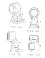
- FIG. 1Ais a front elevation view of a magnet constructed according to the principles of this invention.
- FIG. 1Bis a right side elevation view of the magnet
- FIG. 1Cis a top plan view thereof
- FIG. 1Dis a front perspective view thereof
- FIG. 1Eis a rear perspective view thereof
- FIG. 2Ais a perspective view of a support for pivoting and rotating a magnets in accordance with the principles of this invention, with the magnet in a first position;
- FIG. 2Bis a perspective view of a support for pivoting and rotating a magnets in accordance with the principles of this invention, with the magnet pivoted to a second position;
- FIG. 3Ais a perspective view of a housing containing the magnet and support
- FIG. 3Bis a front elevation view of the housing
- FIG. 3Cis a right side elevation view of the housing
- FIG. 3Dis a top plan view of the housing
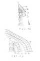
- FIG. 4Ais a perspective view of one quadrant of a magnet block, with several surfaces of equal contribution (represented in wire frame) superposed thereon;
- FIG. 4Bis a top plan view of one quadrant of a magnet block with several surfaces of equal contribution
- FIG. 4Cis a right side elevation view of one quadrant of a magnet block with several surfaces of equal contribution
- FIG. 4Dis a rear elevation view of one quadrant of a magnet block with several surface of equal contribution.
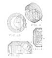
- FIG. 5is a perspective view of the inclusion volume of a magnet constructed according to the principles of this invention, showing the magnet generally centered within the inclusion volume;
- FIG. 6is a front elevation view of the exclusion volume with the magnet in its centered position
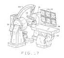
- FIG. 7is a right side elevation view of the exclusion volume with the magnet in its centered position
- FIG. 8is a top plan view of the exclusion volume with the magnet in its centered position
- FIG. 9is a perspective view of the inclusion volume, with the magnet pivoted to the left about the z axis;
- FIG. 10is front elevation view of the inclusion volume of the magnet, with the magnet pivoted to the left;
- FIG. 11is a right side elevation view of the inclusion volume, with the magnet pivoted to the left;
- FIG. 12is a top plan view of the inclusion volume, with the magnet pivoted to the left;
- FIG. 13is a top plan view of a magnet constructed according to the principles of this invention, showing the local magnetic field directions in the space surrounding the magnet;
- FIG. 14is a horizontal cross sectional view of one half of a magnet constructed according to the principles of this invention (the other half being a mirror image thereof), showing the magnetization directions of the segments comprising the magnet, and the local field directions surrounding the magnet and lines of constant magnetic field strength;
- FIG. 15is a graph of maximum coning angle versus distance from the magnet
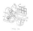
- FIG. 16is a perspective view of a magnetic surgery system incorporating a magnet constructed according to the principles of this invention.
- FIG. 17is a perspective view of a magnetic surgery system incorporating two magnets constructed according to the principles of this invention.
- a magnet constructed according to the principles of this inventionis indicated generally as 20 in FIGS. 1A through 1E .
- the magnet 20comprises a generally cylindrical front face 22 and a back face 24 . There are left top face 26 and a right top face 28 , and a left bottom face 30 and a right bottom face 32 .
- the magnet 20preferably comprises a plurality of parallel bands or segments of permanent magnetic material extending from top to bottom. The magnetization direction of each segment is preferably selected to generally optimize the magnet field at a magnet operating point spaced from the center of the front face of the magnet. This magnet operating point is a design criteria of the magnet.
- the magnet operating pointmay be selected closer to the surface of the magnet, for applications where a magnetic field is to be applied relatively far from the magnet, such as cardiac applications, the magnet operating point may be selected further from the surface of the magnet.
- the magnet operating pointis 13 inches from the center of the front face of the magnet. This represents a reasonable compromise to provide a magnet useful for both neurology and cardiac applications.
- the magnetcould be optimized for some other operating point closer to or further from the front face of the magnet.
- the magnet 20is preferably mounted for pivoting about a first axis A1, generally parallel to the vertical axis of the magnet.
- upper and lower arms 34 and 36project from the back surface 24 of the magnet 20 .
- a cylindrical post 38extends between the arms 34 and 36 , and is journaled in a sleeve 40 .
- the magnetis preferably also mounted for rotation about a second axis A2, that is generally horizontal, and that is perpendicular to, and intersects with, axis A1.
- a sleeve 42extends perpendicularly to sleeve 40 , and is journaled around a horizontal arbor 44 .
- any other mechanism for mounting the magnet 20 to pivot about a first axis, and rotate about a second axis, and in particular to pivot about a first axis that rotates about a second axiscan be used.
- the axis A1is fifteen inches from the front face of the magnet 20
- FIGS. 3A through 3DA housing 50 for containing the magnet and structure for pivoting and rotating the magnet is shown in FIGS. 3A through 3D .
- the housing 50contains the magnet and mechanism so that it is isolated from the procedure. Furthermore, the housing 50 eliminates moving parts from the procedure site, so that the system is less intimidating to the patients, and does not present any hazard to anyone at the procedure site.
- the housing 50accommodates the inclusion zone of the magnet 20 .
- the magnet 20is adapted to pivot about an axis A 1 generally behind the magnet.
- the radius of curvature of the generally cylindrical front face 22corresponds to the distance between the front face and the pivot axis (15inches in this preferred embodiment).
- the back face of the magnetis shaped in accordance with a surface of constant contribution to the magnetic field at the operating point. Material on such a surface contributes equally to the magnetic field at the operating point, regardless of its position on the surface. By selecting the appropriate surface of constant contribution to achieve the desired magnet size and strength, an excluding material that would lie beyond the surface, the weight of the magnet can be optimized for its selected magnetic properties.
- a constant contribution forcecan be calculated or plotted by maximizing the contribution to a particular magnet property at the magnet's operating point, for example the transfer field at the magnet's operating point, and determining the surface of points that contribute equally to the selected magnetic property.
- the superposition of several such surfaces df constant contributionis shown in FIGS. 4A through 4D .
- various surfaces of constant contribution S 1 , S 2 , S 3 , S 4 , S 5 , and S 6are shown, and the final shape of back side of the magnet is determined based upon t constant contribution surface that leaves sufficient magnetic material to achieve the desired field strength, gradient, or field gradient product, while keeping the weight low.
- the magnetis capable of producing a field of at least about 0.4 T at an application point at least 13inches from the surface of the magnet, or about 0.1 T at an application point of 7.5 inches from the surface of the magnet, yet weights less than about 500 pounds.
- An important design criteria for the magnet 20is its inclusion volume, which represents the combination of all of the volumes that the magnet occupies throughout all of the desired possible orientations of the magnet, i.e., all of the desired pivots and rotations.
- the inclusion volume of a magnet constructed according to the principles of this inventionis shown in FIGS. 5 through 8 , with the magnet in a first position within its exclusion zone, and in FIGS. 9 through 12 with the magnet 20 in a second position within its exclusion zone, pivoted 35°, which because of the design of the magnet described above, results in a magnetic field direction shift of 90° at the system's operation point.
- the system's operation pointis a design element, and in this preferred embodiment is thirteen inches from the center of the front face of the inclusion volume, which corresponds to thirteen inches from the center of the front face of the housing 50 .
- the magnet's operation point and the system's operation pointcorrespond when the magnet 20 is in its centered position in its exclusion zone.
- the pivot pointis 15 inches behind the front face of the magnet, and 28 inches (15 plus 13 inches) behind the operating point.
- the pivot pointis generally horizontal, and extends through the pivot axis.
- the inclusion volumeis generally cylindrical, with a beveled forward edge.
- the inclusion volumehas a diameter of about 30 inches and a depth of about 14 inches.
- the bevel on the forward face of the volumeis at approximately 45°, to a depth of about 5 inches, so that the diameter of the generally circular front face is about 20 inches.
- the edge of the magnet 20is shaped so that the magnet 20 remains within the exclusion volume.
- Two magnets 20can be mounted in opposition, so that their magnetic fields add, to provide a useful magnetic field at greater distances, for example to conduct cardiac procedures in the chest, where the application point of the magnetic field is necessarily far away from the magnet.
- the magnet 20when the magnet 20 is in its centered position, it produces a transverse magnetic field at an operating point at the front of the magnet assembly.
- Rotation of the magnet 20 approximately 35° clockwise about an axis parallel to the longitudinal axes of the magnetic segmentsresults in a magnetic field at the operating point at the front of the magnet assembly to point outwardly, away from the magnetic assembly, and rotation of the magnet approximately 35° counterclockwise about that axis results in a magnetic field at the operating point at the front of the magnet assembly to point inwardly, into the magnetic assembly.
- the magnetic field directionchanges 180°.
- This pivotingcombined with rotation of the magnet about the second axis, allows the magnet to create a magnetic field in any direction at the operating point of the assembly, through a simple pivoting and rotation of the magnet, without translation.
- the inclusion volume of the magnetcan be made very small, which means that exclusion volume is small, and access to the patient by health care professionals and medical equipment is not impaired.
- the magnet assembly of the present inventionWhile it is possible with the magnet assembly of the present invention to project a field at the application point in any direction, at sufficient strength to be useful, it may not always be possible to move smoothly and continuously from one magnetic field direction to another in the plane containing both directions. Thus when changing the field from a first direction to the second direction, it is possible that a field direction will temporarily swing out of the plane—a phenomenon known as coning.
- amount of coningdepends upon the distance from the magnet, and as shown in FIG. 14 , the maximum coning is slightly more than 14° from the desired plane, and occurs at distances of about six inches from the magnet. At a distance of 12 inches from the magnet, the maximum coning is about 12.75°.
- a magnetic surgery system incorporating a magnet system constructed according to the principles of the present inventionis indicated generally as 100 in FIG. 16 .
- the system 100includes a magnet 20 and its support and moving structure contained within a housing 50 .
- the system 100is particularly adapted for conduct neurological procedures, and the housing is positioned to be near the patient's bead, in this case at the top of the patient's head.
- the system 100includes a patient support, such a patient bed 102 , which may or may not be movable.
- a C-arm 104mounts bi-planar imaging equipment for making bi-planar images of the procedure site, and displaying them on the displays 106 .
- the bi-planar image equipmentincludes an imaging beam sources, such as x-ray sources 108 , and imaging beam receivers or detectors, such as amorphous silicon last plates 110 , which are substantially unaffected by the presence of magnetic fields.
- the magnet 20 inside the housing 50can be used to navigate a magnetic medical device in the patients head by pivoting the magnet about axis A1and rotating the magnet about axis A2 to achieve the desired magnetic field to orient a magnetic medical device inside the patient's head.
- the bi-planar imagingallows the physician and other health care workers to monitor the orientation and position of the magnetic medical device to navigate the distal end of the magnetic medical device to its desired destination.
- the magnet assemblyis designed to apply a magnet field at the systems' operating point, which, as described above is a point thirteen inches from the front face of the housing 50
- the systempreferably allows the application of a magnetic field in virtually any direction in sufficient strength for navigation purposes, e.g. 0.1 T, anywhere in 7 inch diameter cylinder surrounding the line from the center of the front face of the housing to the system's operating point.
- a magnetic surgery system incorporating two magnet systems constructed according to the principles of the present inventionis indicated generally as 200 in FIG. 17 .
- the system 200includes two magnets 20 and their respective support and moving structures, each contained within a housing 50 .
- the housings 50are disposed on opposite sides of the patients, so that the operating points of each magnet system overlap so that the magnetic fields produced by the two systems are additive.
- the system 200is particularly adapted for cardiac procedures, and the housings 50 are positioned on opposite sides of the patient's chest.
- the system 200includes a patient support, such a patient bed 202 , which may or may not be movable.
- a C-arm 204mounts bi-planar imaging equipment for making bi-planar images of the procedure site, and displaying them on the displays 206 .
- the bi-planar image equipmentincludes an imaging beam sources, such as x-ray sources 208 , and imaging beam receivers or detectors, such as amorphous silicon last plates 210 , which are substantially unaffected by the presence of magnetic fields.
- the magnets 20 inside the housing 50can be used to navigate a magnetic medical device in the patient's head by pivoting the magnet about axis A1 and rotating the magnet about axis A2 to achieve the desired magnetic field to orient a magnetic medical device inside the patient's head.
- the bi-planar imagingallows the physician and other health care workers to monitor the orientation and position of the magnetic medical device to navigate the distal end of the magnetic medical device to its desired destination.
- the magnet assemblyis designed to apply a magnet field at the systems' operating point, which, as described above is a point thirteen inches from the front face of the housing 50
- the systempreferably allows the application of a magnetic field in virtually any direction in sufficient strength for navigation purposes, e.g. 0.04 T, anywhere in 7 inch diameter circle thirteen inches from the front face of the housing.
Landscapes
- Health & Medical Sciences (AREA)
- Engineering & Computer Science (AREA)
- Surgery (AREA)
- Life Sciences & Earth Sciences (AREA)
- Medical Informatics (AREA)
- General Health & Medical Sciences (AREA)
- Biomedical Technology (AREA)
- Heart & Thoracic Surgery (AREA)
- Nuclear Medicine, Radiotherapy & Molecular Imaging (AREA)
- Molecular Biology (AREA)
- Animal Behavior & Ethology (AREA)
- Robotics (AREA)
- Public Health (AREA)
- Veterinary Medicine (AREA)
- Physics & Mathematics (AREA)
- Electromagnetism (AREA)
- Power Engineering (AREA)
- Magnetic Resonance Imaging Apparatus (AREA)
Abstract
Description
Claims (12)
Priority Applications (9)
| Application Number | Priority Date | Filing Date | Title |
|---|---|---|---|
| US10/056,227US6975197B2 (en) | 2002-01-23 | 2002-01-23 | Rotating and pivoting magnet for magnetic navigation |
| PCT/US2002/008587WO2003083880A1 (en) | 2002-01-23 | 2002-03-19 | Rotating and pivoting magnet for magnetic navigation |
| US10/347,525US7019610B2 (en) | 2002-01-23 | 2003-01-17 | Magnetic navigation system |
| US10/946,634US7313429B2 (en) | 2002-01-23 | 2004-09-21 | Rotating and pivoting magnet for magnetic navigation |
| PCT/US2005/033748WO2006137877A2 (en) | 2002-01-23 | 2005-09-20 | Rotating and pivoting magnet for magnetic navigation |
| US11/296,190US7161453B2 (en) | 2002-01-23 | 2005-12-07 | Rotating and pivoting magnet for magnetic navigation |
| US11/389,554US20070016010A1 (en) | 2002-01-23 | 2006-03-24 | Magnetic navigation system |
| US11/650,856US20080016677A1 (en) | 2002-01-23 | 2007-01-08 | Rotating and pivoting magnet for magnetic navigation |
| US11/699,003US7966059B2 (en) | 1999-10-04 | 2007-01-26 | Rotating and pivoting magnet for magnetic navigation |
Applications Claiming Priority (2)
| Application Number | Priority Date | Filing Date | Title |
|---|---|---|---|
| US10/056,227US6975197B2 (en) | 2002-01-23 | 2002-01-23 | Rotating and pivoting magnet for magnetic navigation |
| PCT/US2002/008587WO2003083880A1 (en) | 2002-01-23 | 2002-03-19 | Rotating and pivoting magnet for magnetic navigation |
Related Child Applications (2)
| Application Number | Title | Priority Date | Filing Date |
|---|---|---|---|
| US10/347,525Continuation-In-PartUS7019610B2 (en) | 1999-10-04 | 2003-01-17 | Magnetic navigation system |
| US11/296,190ContinuationUS7161453B2 (en) | 2002-01-23 | 2005-12-07 | Rotating and pivoting magnet for magnetic navigation |
Publications (2)
| Publication Number | Publication Date |
|---|---|
| US20030137380A1 US20030137380A1 (en) | 2003-07-24 |
| US6975197B2true US6975197B2 (en) | 2005-12-13 |
Family
ID=30002461
Family Applications (1)
| Application Number | Title | Priority Date | Filing Date |
|---|---|---|---|
| US10/056,227Expired - LifetimeUS6975197B2 (en) | 1999-10-04 | 2002-01-23 | Rotating and pivoting magnet for magnetic navigation |
Country Status (2)
| Country | Link |
|---|---|
| US (1) | US6975197B2 (en) |
| WO (1) | WO2003083880A1 (en) |
Cited By (93)
| Publication number | Priority date | Publication date | Assignee | Title |
|---|---|---|---|---|
| US20040249263A1 (en)* | 2003-03-13 | 2004-12-09 | Creighton Francis M. | Magnetic navigation system and magnet system therefor |
| US20060009735A1 (en)* | 2004-06-29 | 2006-01-12 | Viswanathan Raju R | Navigation of remotely actuable medical device using control variable and length |
| US20060062347A1 (en)* | 2004-09-22 | 2006-03-23 | Siemens Aktiengesellschaft | Device for guiding a magnetic element |
| US20060094956A1 (en)* | 2004-10-29 | 2006-05-04 | Viswanathan Raju R | Restricted navigation controller for, and methods of controlling, a remote navigation system |
| US20060144407A1 (en)* | 2004-07-20 | 2006-07-06 | Anthony Aliberto | Magnetic navigation manipulation apparatus |
| US20060269108A1 (en)* | 2005-02-07 | 2006-11-30 | Viswanathan Raju R | Registration of three dimensional image data to 2D-image-derived data |
| US20060276867A1 (en)* | 2005-06-02 | 2006-12-07 | Viswanathan Raju R | Methods and devices for mapping the ventricle for pacing lead placement and therapy delivery |
| US20060281989A1 (en)* | 2005-05-06 | 2006-12-14 | Viswanathan Raju R | Voice controlled user interface for remote navigation systems |
| US20060278246A1 (en)* | 2003-05-21 | 2006-12-14 | Michael Eng | Electrophysiology catheter |
| US20070021742A1 (en)* | 2005-07-18 | 2007-01-25 | Viswanathan Raju R | Estimation of contact force by a medical device |
| US20070021731A1 (en)* | 1997-11-12 | 2007-01-25 | Garibaldi Jeffrey M | Method of and apparatus for navigating medical devices in body lumens |
| US20070021744A1 (en)* | 2005-07-07 | 2007-01-25 | Creighton Francis M Iv | Apparatus and method for performing ablation with imaging feedback |
| US20070030958A1 (en)* | 2005-07-15 | 2007-02-08 | Munger Gareth T | Magnetically shielded x-ray tube |
| US20070038064A1 (en)* | 2005-07-08 | 2007-02-15 | Creighton Francis M Iv | Magnetic navigation and imaging system |
| US20070038410A1 (en)* | 2005-08-10 | 2007-02-15 | Ilker Tunay | Method and apparatus for dynamic magnetic field control using multiple magnets |
| US20070038065A1 (en)* | 2005-07-07 | 2007-02-15 | Creighton Francis M Iv | Operation of a remote medical navigation system using ultrasound image |
| US20070040670A1 (en)* | 2005-07-26 | 2007-02-22 | Viswanathan Raju R | System and network for remote medical procedures |
| US20070043455A1 (en)* | 2005-07-26 | 2007-02-22 | Viswanathan Raju R | Apparatus and methods for automated sequential movement control for operation of a remote navigation system |
| US20070055124A1 (en)* | 2005-09-01 | 2007-03-08 | Viswanathan Raju R | Method and system for optimizing left-heart lead placement |
| US20070088077A1 (en)* | 1991-02-26 | 2007-04-19 | Plasse Terry F | Appetite stimulation and reduction of weight loss in patients suffering from symptomatic hiv infection |
| US20070088197A1 (en)* | 2000-02-16 | 2007-04-19 | Sterotaxis, Inc. | Magnetic medical devices with changeable magnetic moments and method of navigating magnetic medical devices with changeable magnetic moments |
| US7276044B2 (en) | 2001-05-06 | 2007-10-02 | Stereotaxis, Inc. | System and methods for advancing a catheter |
| US7537570B2 (en) | 2006-09-11 | 2009-05-26 | Stereotaxis, Inc. | Automated mapping of anatomical features of heart chambers |
| US7543239B2 (en) | 2004-06-04 | 2009-06-02 | Stereotaxis, Inc. | User interface for remote control of medical devices |
| US7567233B2 (en) | 2006-09-06 | 2009-07-28 | Stereotaxis, Inc. | Global input device for multiple computer-controlled medical systems |
| US7690619B2 (en) | 2005-07-12 | 2010-04-06 | Stereotaxis, Inc. | Apparatus for pivotally orienting a projection device |
| US7708696B2 (en) | 2005-01-11 | 2010-05-04 | Stereotaxis, Inc. | Navigation using sensed physiological data as feedback |
| US7747960B2 (en) | 2006-09-06 | 2010-06-29 | Stereotaxis, Inc. | Control for, and method of, operating at least two medical systems |
| US7751867B2 (en) | 2004-12-20 | 2010-07-06 | Stereotaxis, Inc. | Contact over-torque with three-dimensional anatomical data |
| US7757694B2 (en) | 1999-10-04 | 2010-07-20 | Stereotaxis, Inc. | Method for safely and efficiently navigating magnetic devices in the body |
| US7769444B2 (en) | 2005-07-11 | 2010-08-03 | Stereotaxis, Inc. | Method of treating cardiac arrhythmias |
| US7766856B2 (en) | 2001-05-06 | 2010-08-03 | Stereotaxis, Inc. | System and methods for advancing a catheter |
| US7818076B2 (en) | 2005-07-26 | 2010-10-19 | Stereotaxis, Inc. | Method and apparatus for multi-system remote surgical navigation from a single control center |
| US7831294B2 (en) | 2004-10-07 | 2010-11-09 | Stereotaxis, Inc. | System and method of surgical imagining with anatomical overlay for navigation of surgical devices |
| US20110118590A1 (en)* | 2009-11-18 | 2011-05-19 | Siemens Medical Solutions Usa, Inc. | System For Continuous Cardiac Imaging And Mapping |
| US7961924B2 (en) | 2006-08-21 | 2011-06-14 | Stereotaxis, Inc. | Method of three-dimensional device localization using single-plane imaging |
| US7966059B2 (en) | 1999-10-04 | 2011-06-21 | Stereotaxis, Inc. | Rotating and pivoting magnet for magnetic navigation |
| US8024024B2 (en) | 2007-06-27 | 2011-09-20 | Stereotaxis, Inc. | Remote control of medical devices using real time location data |
| US8060184B2 (en) | 2002-06-28 | 2011-11-15 | Stereotaxis, Inc. | Method of navigating medical devices in the presence of radiopaque material |
| US8114032B2 (en)* | 2001-05-06 | 2012-02-14 | Stereotaxis, Inc. | Systems and methods for medical device advancement and rotation |
| US8135185B2 (en) | 2006-10-20 | 2012-03-13 | Stereotaxis, Inc. | Location and display of occluded portions of vessels on 3-D angiographic images |
| US8196590B2 (en) | 2003-05-02 | 2012-06-12 | Stereotaxis, Inc. | Variable magnetic moment MR navigation |
| US8231618B2 (en) | 2007-11-05 | 2012-07-31 | Stereotaxis, Inc. | Magnetically guided energy delivery apparatus |
| US8244824B2 (en) | 2006-09-06 | 2012-08-14 | Stereotaxis, Inc. | Coordinated control for multiple computer-controlled medical systems |
| US8242972B2 (en) | 2006-09-06 | 2012-08-14 | Stereotaxis, Inc. | System state driven display for medical procedures |
| US8273081B2 (en) | 2006-09-08 | 2012-09-25 | Stereotaxis, Inc. | Impedance-based cardiac therapy planning method with a remote surgical navigation system |
| US8308628B2 (en) | 2009-11-02 | 2012-11-13 | Pulse Therapeutics, Inc. | Magnetic-based systems for treating occluded vessels |
| US8419681B2 (en) | 2002-11-18 | 2013-04-16 | Stereotaxis, Inc. | Magnetically navigable balloon catheters |
| US8437833B2 (en) | 2008-10-07 | 2013-05-07 | Bard Access Systems, Inc. | Percutaneous magnetic gastrostomy |
| US20130139832A1 (en)* | 2009-02-25 | 2013-06-06 | Benjamin Shapiro | Devices, systems and methods for magnetic-assisted therapeutic agent delivery |
| US8478382B2 (en) | 2008-02-11 | 2013-07-02 | C. R. Bard, Inc. | Systems and methods for positioning a catheter |
| US8512256B2 (en) | 2006-10-23 | 2013-08-20 | Bard Access Systems, Inc. | Method of locating the tip of a central venous catheter |
| US8774907B2 (en) | 2006-10-23 | 2014-07-08 | Bard Access Systems, Inc. | Method of locating the tip of a central venous catheter |
| US8781555B2 (en) | 2007-11-26 | 2014-07-15 | C. R. Bard, Inc. | System for placement of a catheter including a signal-generating stylet |
| US8784336B2 (en) | 2005-08-24 | 2014-07-22 | C. R. Bard, Inc. | Stylet apparatuses and methods of manufacture |
| US20140213139A1 (en)* | 2013-01-31 | 2014-07-31 | Joshua Willard Ferguson | Magnetic construction system and method |
| US8801693B2 (en) | 2010-10-29 | 2014-08-12 | C. R. Bard, Inc. | Bioimpedance-assisted placement of a medical device |
| US8849382B2 (en) | 2007-11-26 | 2014-09-30 | C. R. Bard, Inc. | Apparatus and display methods relating to intravascular placement of a catheter |
| USD724745S1 (en) | 2011-08-09 | 2015-03-17 | C. R. Bard, Inc. | Cap for an ultrasound probe |
| US9111016B2 (en) | 2007-07-06 | 2015-08-18 | Stereotaxis, Inc. | Management of live remote medical display |
| US9125578B2 (en) | 2009-06-12 | 2015-09-08 | Bard Access Systems, Inc. | Apparatus and method for catheter navigation and tip location |
| US9211107B2 (en) | 2011-11-07 | 2015-12-15 | C. R. Bard, Inc. | Ruggedized ultrasound hydrogel insert |
| USD754357S1 (en) | 2011-08-09 | 2016-04-19 | C. R. Bard, Inc. | Ultrasound probe head |
| US9314222B2 (en) | 2005-07-07 | 2016-04-19 | Stereotaxis, Inc. | Operation of a remote medical navigation system using ultrasound image |
| US9339206B2 (en) | 2009-06-12 | 2016-05-17 | Bard Access Systems, Inc. | Adaptor for endovascular electrocardiography |
| US9445734B2 (en) | 2009-06-12 | 2016-09-20 | Bard Access Systems, Inc. | Devices and methods for endovascular electrography |
| US9456766B2 (en) | 2007-11-26 | 2016-10-04 | C. R. Bard, Inc. | Apparatus for use with needle insertion guidance system |
| US9492097B2 (en) | 2007-11-26 | 2016-11-15 | C. R. Bard, Inc. | Needle length determination and calibration for insertion guidance system |
| US9521961B2 (en) | 2007-11-26 | 2016-12-20 | C. R. Bard, Inc. | Systems and methods for guiding a medical instrument |
| US9532724B2 (en) | 2009-06-12 | 2017-01-03 | Bard Access Systems, Inc. | Apparatus and method for catheter navigation using endovascular energy mapping |
| US9554716B2 (en) | 2007-11-26 | 2017-01-31 | C. R. Bard, Inc. | Insertion guidance system for needles and medical components |
| US9636031B2 (en) | 2007-11-26 | 2017-05-02 | C.R. Bard, Inc. | Stylets for use with apparatus for intravascular placement of a catheter |
| US9649048B2 (en) | 2007-11-26 | 2017-05-16 | C. R. Bard, Inc. | Systems and methods for breaching a sterile field for intravascular placement of a catheter |
| US9681823B2 (en) | 2007-11-26 | 2017-06-20 | C. R. Bard, Inc. | Integrated system for intravascular placement of a catheter |
| US9839372B2 (en) | 2014-02-06 | 2017-12-12 | C. R. Bard, Inc. | Systems and methods for guidance and placement of an intravascular device |
| US9883878B2 (en) | 2012-05-15 | 2018-02-06 | Pulse Therapeutics, Inc. | Magnetic-based systems and methods for manipulation of magnetic particles |
| US9901714B2 (en) | 2008-08-22 | 2018-02-27 | C. R. Bard, Inc. | Catheter assembly including ECG sensor and magnetic assemblies |
| US10046139B2 (en) | 2010-08-20 | 2018-08-14 | C. R. Bard, Inc. | Reconfirmation of ECG-assisted catheter tip placement |
| US10349890B2 (en) | 2015-06-26 | 2019-07-16 | C. R. Bard, Inc. | Connector interface for ECG-based catheter positioning system |
| US10449330B2 (en) | 2007-11-26 | 2019-10-22 | C. R. Bard, Inc. | Magnetic element-equipped needle assemblies |
| US10524691B2 (en) | 2007-11-26 | 2020-01-07 | C. R. Bard, Inc. | Needle assembly including an aligned magnetic element |
| US10537713B2 (en) | 2009-05-25 | 2020-01-21 | Stereotaxis, Inc. | Remote manipulator device |
| US10639008B2 (en) | 2009-10-08 | 2020-05-05 | C. R. Bard, Inc. | Support and cover structures for an ultrasound probe head |
| US10751509B2 (en) | 2007-11-26 | 2020-08-25 | C. R. Bard, Inc. | Iconic representations for guidance of an indwelling medical device |
| US10820885B2 (en) | 2012-06-15 | 2020-11-03 | C. R. Bard, Inc. | Apparatus and methods for detection of a removable cap on an ultrasound probe |
| US10973584B2 (en) | 2015-01-19 | 2021-04-13 | Bard Access Systems, Inc. | Device and method for vascular access |
| US10992079B2 (en) | 2018-10-16 | 2021-04-27 | Bard Access Systems, Inc. | Safety-equipped connection systems and methods thereof for establishing electrical connections |
| US11000207B2 (en) | 2016-01-29 | 2021-05-11 | C. R. Bard, Inc. | Multiple coil system for tracking a medical device |
| US11103213B2 (en) | 2009-10-08 | 2021-08-31 | C. R. Bard, Inc. | Spacers for use with an ultrasound probe |
| US11890226B2 (en) | 2009-02-25 | 2024-02-06 | University Of Maryland, College Park | Device and methods for directing agents into an eye |
| US11894186B2 (en) | 2020-06-17 | 2024-02-06 | Multi-Scale Medical Robotics Center Limited | Parallel mobile coil mechanism for magnetic manipulation in large workspace |
| US11918315B2 (en) | 2018-05-03 | 2024-03-05 | Pulse Therapeutics, Inc. | Determination of structure and traversal of occlusions using magnetic particles |
| US12171443B1 (en) | 2021-03-09 | 2024-12-24 | Pulse Therapeutics, Inc. | Magnetically controlled flow generation |
Families Citing this family (4)
| Publication number | Priority date | Publication date | Assignee | Title |
|---|---|---|---|---|
| DE102006000709A1 (en)* | 2006-01-03 | 2007-07-12 | Siemens Ag | Navigation device comprising a magnetic field generating device for generating a magnetic field for moving a medical instrument, in particular a catheter |
| WO2008007771A1 (en)* | 2006-07-13 | 2008-01-17 | Hitachi Metals, Ltd. | Magnetic field control method and magnetic field generator |
| DE102006045176A1 (en)* | 2006-09-25 | 2008-04-03 | Siemens Ag | Medical examination and treatment device for treatment of disease of heart or other hollow organs minimum invasive interferences are taken by medical instrument, has electromagnet for generating magnetic field for navigation of instruments |
| DE102007037846A1 (en) | 2007-08-10 | 2009-02-19 | Siemens Ag | Medical device e.g. endoscopic instrument, position determining device for use in human body, has position determining device determining position by using body model, which describes preset body by electrical and magnetic fabric parameters |
Citations (9)
| Publication number | Priority date | Publication date | Assignee | Title |
|---|---|---|---|---|
| US5257636A (en) | 1991-04-02 | 1993-11-02 | Steven J. White | Apparatus for determining position of an endothracheal tube |
| US5312321A (en) | 1986-11-21 | 1994-05-17 | Holcomb Technology, Inc. | Method and apparatus for suppressing neuron action potential firings |
| US5622169A (en) | 1993-09-14 | 1997-04-22 | University Of Washington | Apparatus and method for locating a medical tube in the body of a patient |
| US5667469A (en)* | 1993-10-08 | 1997-09-16 | Zhang; Xiaoyun | Strong magnetism therapeutic apparatus with permanent-magnets rotating at low frequency |
| US5681260A (en) | 1989-09-22 | 1997-10-28 | Olympus Optical Co., Ltd. | Guiding apparatus for guiding an insertable body within an inspected object |
| US6157281A (en)* | 1996-07-24 | 2000-12-05 | Odin Technologies, Ltd. | Permanent magnet assemblies for use in medical applications |
| US6241671B1 (en)* | 1998-11-03 | 2001-06-05 | Stereotaxis, Inc. | Open field system for magnetic surgery |
| US6304768B1 (en)* | 1997-11-12 | 2001-10-16 | Stereotaxis, Inc. | Method and apparatus using shaped field of repositionable magnet to guide implant |
| US6630879B1 (en) | 1999-02-04 | 2003-10-07 | Stereotaxis, Inc. | Efficient magnet system for magnetically-assisted surgery |
Family Cites Families (3)
| Publication number | Priority date | Publication date | Assignee | Title |
|---|---|---|---|---|
| US5049848A (en)* | 1989-11-28 | 1991-09-17 | Pulyer Yuly M | High field strength magnet, preferably having remote shimming of field |
| US5216400A (en)* | 1992-06-02 | 1993-06-01 | The United States Of America As Represented By The Secretary Of The Army | Magnetic field sources for producing high-intensity variable fields |
| US5495222A (en)* | 1994-04-15 | 1996-02-27 | New York University | Open permanent magnet structure for generating highly uniform field |
- 2002
- 2002-01-23USUS10/056,227patent/US6975197B2/ennot_activeExpired - Lifetime
- 2002-03-19WOPCT/US2002/008587patent/WO2003083880A1/ennot_activeApplication Discontinuation
Patent Citations (9)
| Publication number | Priority date | Publication date | Assignee | Title |
|---|---|---|---|---|
| US5312321A (en) | 1986-11-21 | 1994-05-17 | Holcomb Technology, Inc. | Method and apparatus for suppressing neuron action potential firings |
| US5681260A (en) | 1989-09-22 | 1997-10-28 | Olympus Optical Co., Ltd. | Guiding apparatus for guiding an insertable body within an inspected object |
| US5257636A (en) | 1991-04-02 | 1993-11-02 | Steven J. White | Apparatus for determining position of an endothracheal tube |
| US5622169A (en) | 1993-09-14 | 1997-04-22 | University Of Washington | Apparatus and method for locating a medical tube in the body of a patient |
| US5667469A (en)* | 1993-10-08 | 1997-09-16 | Zhang; Xiaoyun | Strong magnetism therapeutic apparatus with permanent-magnets rotating at low frequency |
| US6157281A (en)* | 1996-07-24 | 2000-12-05 | Odin Technologies, Ltd. | Permanent magnet assemblies for use in medical applications |
| US6304768B1 (en)* | 1997-11-12 | 2001-10-16 | Stereotaxis, Inc. | Method and apparatus using shaped field of repositionable magnet to guide implant |
| US6241671B1 (en)* | 1998-11-03 | 2001-06-05 | Stereotaxis, Inc. | Open field system for magnetic surgery |
| US6630879B1 (en) | 1999-02-04 | 2003-10-07 | Stereotaxis, Inc. | Efficient magnet system for magnetically-assisted surgery |
Cited By (166)
| Publication number | Priority date | Publication date | Assignee | Title |
|---|---|---|---|---|
| US20070088077A1 (en)* | 1991-02-26 | 2007-04-19 | Plasse Terry F | Appetite stimulation and reduction of weight loss in patients suffering from symptomatic hiv infection |
| US20070021731A1 (en)* | 1997-11-12 | 2007-01-25 | Garibaldi Jeffrey M | Method of and apparatus for navigating medical devices in body lumens |
| US7771415B2 (en) | 1999-10-04 | 2010-08-10 | Stereotaxis, Inc. | Method for safely and efficiently navigating magnetic devices in the body |
| US7757694B2 (en) | 1999-10-04 | 2010-07-20 | Stereotaxis, Inc. | Method for safely and efficiently navigating magnetic devices in the body |
| US7966059B2 (en) | 1999-10-04 | 2011-06-21 | Stereotaxis, Inc. | Rotating and pivoting magnet for magnetic navigation |
| US7341063B2 (en) | 2000-02-16 | 2008-03-11 | Stereotaxis, Inc. | Magnetic medical devices with changeable magnetic moments and method of navigating magnetic medical devices with changeable magnetic moments |
| US20070088197A1 (en)* | 2000-02-16 | 2007-04-19 | Sterotaxis, Inc. | Magnetic medical devices with changeable magnetic moments and method of navigating magnetic medical devices with changeable magnetic moments |
| US8114032B2 (en)* | 2001-05-06 | 2012-02-14 | Stereotaxis, Inc. | Systems and methods for medical device advancement and rotation |
| US7276044B2 (en) | 2001-05-06 | 2007-10-02 | Stereotaxis, Inc. | System and methods for advancing a catheter |
| US7766856B2 (en) | 2001-05-06 | 2010-08-03 | Stereotaxis, Inc. | System and methods for advancing a catheter |
| US8060184B2 (en) | 2002-06-28 | 2011-11-15 | Stereotaxis, Inc. | Method of navigating medical devices in the presence of radiopaque material |
| US8419681B2 (en) | 2002-11-18 | 2013-04-16 | Stereotaxis, Inc. | Magnetically navigable balloon catheters |
| US7305263B2 (en)* | 2003-03-13 | 2007-12-04 | Stereotaxis, Inc. | Magnetic navigation system and magnet system therefor |
| US20040249263A1 (en)* | 2003-03-13 | 2004-12-09 | Creighton Francis M. | Magnetic navigation system and magnet system therefor |
| US8196590B2 (en) | 2003-05-02 | 2012-06-12 | Stereotaxis, Inc. | Variable magnetic moment MR navigation |
| US20060278246A1 (en)* | 2003-05-21 | 2006-12-14 | Michael Eng | Electrophysiology catheter |
| US7346379B2 (en) | 2003-05-21 | 2008-03-18 | Stereotaxis, Inc. | Electrophysiology catheter |
| US7543239B2 (en) | 2004-06-04 | 2009-06-02 | Stereotaxis, Inc. | User interface for remote control of medical devices |
| US20060025676A1 (en)* | 2004-06-29 | 2006-02-02 | Stereotaxis, Inc. | Navigation of remotely actuable medical device using control variable and length |
| US7769428B2 (en) | 2004-06-29 | 2010-08-03 | Stereotaxis, Inc. | Navigation of remotely actuable medical device using control variable and length |
| US20060025675A1 (en)* | 2004-06-29 | 2006-02-02 | Stereotaxis, Inc. | Navigation of remotely actuable medical device using control variable and length |
| US20060025719A1 (en)* | 2004-06-29 | 2006-02-02 | Stereotaxis, Inc. | Navigation of remotely actuable medical device using control variable and length |
| US7761133B2 (en) | 2004-06-29 | 2010-07-20 | Stereotaxis, Inc. | Navigation of remotely actuable medical device using control variable and length |
| US20060036213A1 (en)* | 2004-06-29 | 2006-02-16 | Stereotaxis, Inc. | Navigation of remotely actuable medical device using control variable and length |
| US7853306B2 (en) | 2004-06-29 | 2010-12-14 | Stereotaxis, Inc. | Navigation of remotely actuable medical device using control variable and length |
| US20060009735A1 (en)* | 2004-06-29 | 2006-01-12 | Viswanathan Raju R | Navigation of remotely actuable medical device using control variable and length |
| US20060144407A1 (en)* | 2004-07-20 | 2006-07-06 | Anthony Aliberto | Magnetic navigation manipulation apparatus |
| US7616983B2 (en)* | 2004-09-22 | 2009-11-10 | Siemens Aktiengesellschaft | Device for guiding a magnetic element |
| US20060062347A1 (en)* | 2004-09-22 | 2006-03-23 | Siemens Aktiengesellschaft | Device for guiding a magnetic element |
| US7831294B2 (en) | 2004-10-07 | 2010-11-09 | Stereotaxis, Inc. | System and method of surgical imagining with anatomical overlay for navigation of surgical devices |
| US20060094956A1 (en)* | 2004-10-29 | 2006-05-04 | Viswanathan Raju R | Restricted navigation controller for, and methods of controlling, a remote navigation system |
| US7751867B2 (en) | 2004-12-20 | 2010-07-06 | Stereotaxis, Inc. | Contact over-torque with three-dimensional anatomical data |
| US8369934B2 (en) | 2004-12-20 | 2013-02-05 | Stereotaxis, Inc. | Contact over-torque with three-dimensional anatomical data |
| US7708696B2 (en) | 2005-01-11 | 2010-05-04 | Stereotaxis, Inc. | Navigation using sensed physiological data as feedback |
| US20060269108A1 (en)* | 2005-02-07 | 2006-11-30 | Viswanathan Raju R | Registration of three dimensional image data to 2D-image-derived data |
| US7756308B2 (en) | 2005-02-07 | 2010-07-13 | Stereotaxis, Inc. | Registration of three dimensional image data to 2D-image-derived data |
| US7961926B2 (en) | 2005-02-07 | 2011-06-14 | Stereotaxis, Inc. | Registration of three-dimensional image data to 2D-image-derived data |
| US7742803B2 (en) | 2005-05-06 | 2010-06-22 | Stereotaxis, Inc. | Voice controlled user interface for remote navigation systems |
| US20060281989A1 (en)* | 2005-05-06 | 2006-12-14 | Viswanathan Raju R | Voice controlled user interface for remote navigation systems |
| US20060276867A1 (en)* | 2005-06-02 | 2006-12-07 | Viswanathan Raju R | Methods and devices for mapping the ventricle for pacing lead placement and therapy delivery |
| US20070038065A1 (en)* | 2005-07-07 | 2007-02-15 | Creighton Francis M Iv | Operation of a remote medical navigation system using ultrasound image |
| US9314222B2 (en) | 2005-07-07 | 2016-04-19 | Stereotaxis, Inc. | Operation of a remote medical navigation system using ultrasound image |
| US20070021744A1 (en)* | 2005-07-07 | 2007-01-25 | Creighton Francis M Iv | Apparatus and method for performing ablation with imaging feedback |
| US20070038064A1 (en)* | 2005-07-08 | 2007-02-15 | Creighton Francis M Iv | Magnetic navigation and imaging system |
| US7603905B2 (en) | 2005-07-08 | 2009-10-20 | Stereotaxis, Inc. | Magnetic navigation and imaging system |
| US7769444B2 (en) | 2005-07-11 | 2010-08-03 | Stereotaxis, Inc. | Method of treating cardiac arrhythmias |
| US7690619B2 (en) | 2005-07-12 | 2010-04-06 | Stereotaxis, Inc. | Apparatus for pivotally orienting a projection device |
| US20070030958A1 (en)* | 2005-07-15 | 2007-02-08 | Munger Gareth T | Magnetically shielded x-ray tube |
| US7416335B2 (en) | 2005-07-15 | 2008-08-26 | Sterotaxis, Inc. | Magnetically shielded x-ray tube |
| US8192374B2 (en) | 2005-07-18 | 2012-06-05 | Stereotaxis, Inc. | Estimation of contact force by a medical device |
| US20070021742A1 (en)* | 2005-07-18 | 2007-01-25 | Viswanathan Raju R | Estimation of contact force by a medical device |
| US7818076B2 (en) | 2005-07-26 | 2010-10-19 | Stereotaxis, Inc. | Method and apparatus for multi-system remote surgical navigation from a single control center |
| US20070040670A1 (en)* | 2005-07-26 | 2007-02-22 | Viswanathan Raju R | System and network for remote medical procedures |
| US20070043455A1 (en)* | 2005-07-26 | 2007-02-22 | Viswanathan Raju R | Apparatus and methods for automated sequential movement control for operation of a remote navigation system |
| US7772950B2 (en) | 2005-08-10 | 2010-08-10 | Stereotaxis, Inc. | Method and apparatus for dynamic magnetic field control using multiple magnets |
| US20070038410A1 (en)* | 2005-08-10 | 2007-02-15 | Ilker Tunay | Method and apparatus for dynamic magnetic field control using multiple magnets |
| US7495537B2 (en)* | 2005-08-10 | 2009-02-24 | Stereotaxis, Inc. | Method and apparatus for dynamic magnetic field control using multiple magnets |
| US11207496B2 (en) | 2005-08-24 | 2021-12-28 | C. R. Bard, Inc. | Stylet apparatuses and methods of manufacture |
| US8784336B2 (en) | 2005-08-24 | 2014-07-22 | C. R. Bard, Inc. | Stylet apparatuses and methods of manufacture |
| US10004875B2 (en) | 2005-08-24 | 2018-06-26 | C. R. Bard, Inc. | Stylet apparatuses and methods of manufacture |
| US20070055124A1 (en)* | 2005-09-01 | 2007-03-08 | Viswanathan Raju R | Method and system for optimizing left-heart lead placement |
| US7961924B2 (en) | 2006-08-21 | 2011-06-14 | Stereotaxis, Inc. | Method of three-dimensional device localization using single-plane imaging |
| US8242972B2 (en) | 2006-09-06 | 2012-08-14 | Stereotaxis, Inc. | System state driven display for medical procedures |
| US8244824B2 (en) | 2006-09-06 | 2012-08-14 | Stereotaxis, Inc. | Coordinated control for multiple computer-controlled medical systems |
| US8806359B2 (en) | 2006-09-06 | 2014-08-12 | Stereotaxis, Inc. | Workflow driven display for medical procedures |
| US8799792B2 (en) | 2006-09-06 | 2014-08-05 | Stereotaxis, Inc. | Workflow driven method of performing multi-step medical procedures |
| US7747960B2 (en) | 2006-09-06 | 2010-06-29 | Stereotaxis, Inc. | Control for, and method of, operating at least two medical systems |
| US7567233B2 (en) | 2006-09-06 | 2009-07-28 | Stereotaxis, Inc. | Global input device for multiple computer-controlled medical systems |
| US8273081B2 (en) | 2006-09-08 | 2012-09-25 | Stereotaxis, Inc. | Impedance-based cardiac therapy planning method with a remote surgical navigation system |
| US7537570B2 (en) | 2006-09-11 | 2009-05-26 | Stereotaxis, Inc. | Automated mapping of anatomical features of heart chambers |
| US8135185B2 (en) | 2006-10-20 | 2012-03-13 | Stereotaxis, Inc. | Location and display of occluded portions of vessels on 3-D angiographic images |
| US8858455B2 (en) | 2006-10-23 | 2014-10-14 | Bard Access Systems, Inc. | Method of locating the tip of a central venous catheter |
| US9265443B2 (en) | 2006-10-23 | 2016-02-23 | Bard Access Systems, Inc. | Method of locating the tip of a central venous catheter |
| US8512256B2 (en) | 2006-10-23 | 2013-08-20 | Bard Access Systems, Inc. | Method of locating the tip of a central venous catheter |
| US8774907B2 (en) | 2006-10-23 | 2014-07-08 | Bard Access Systems, Inc. | Method of locating the tip of a central venous catheter |
| US9345422B2 (en) | 2006-10-23 | 2016-05-24 | Bard Acess Systems, Inc. | Method of locating the tip of a central venous catheter |
| US9833169B2 (en) | 2006-10-23 | 2017-12-05 | Bard Access Systems, Inc. | Method of locating the tip of a central venous catheter |
| US8024024B2 (en) | 2007-06-27 | 2011-09-20 | Stereotaxis, Inc. | Remote control of medical devices using real time location data |
| US9111016B2 (en) | 2007-07-06 | 2015-08-18 | Stereotaxis, Inc. | Management of live remote medical display |
| US8231618B2 (en) | 2007-11-05 | 2012-07-31 | Stereotaxis, Inc. | Magnetically guided energy delivery apparatus |
| US8849382B2 (en) | 2007-11-26 | 2014-09-30 | C. R. Bard, Inc. | Apparatus and display methods relating to intravascular placement of a catheter |
| US10751509B2 (en) | 2007-11-26 | 2020-08-25 | C. R. Bard, Inc. | Iconic representations for guidance of an indwelling medical device |
| US10165962B2 (en) | 2007-11-26 | 2019-01-01 | C. R. Bard, Inc. | Integrated systems for intravascular placement of a catheter |
| US8781555B2 (en) | 2007-11-26 | 2014-07-15 | C. R. Bard, Inc. | System for placement of a catheter including a signal-generating stylet |
| US11779240B2 (en) | 2007-11-26 | 2023-10-10 | C. R. Bard, Inc. | Systems and methods for breaching a sterile field for intravascular placement of a catheter |
| US11707205B2 (en) | 2007-11-26 | 2023-07-25 | C. R. Bard, Inc. | Integrated system for intravascular placement of a catheter |
| US9681823B2 (en) | 2007-11-26 | 2017-06-20 | C. R. Bard, Inc. | Integrated system for intravascular placement of a catheter |
| US11529070B2 (en) | 2007-11-26 | 2022-12-20 | C. R. Bard, Inc. | System and methods for guiding a medical instrument |
| US11134915B2 (en) | 2007-11-26 | 2021-10-05 | C. R. Bard, Inc. | System for placement of a catheter including a signal-generating stylet |
| US11123099B2 (en) | 2007-11-26 | 2021-09-21 | C. R. Bard, Inc. | Apparatus for use with needle insertion guidance system |
| US10105121B2 (en) | 2007-11-26 | 2018-10-23 | C. R. Bard, Inc. | System for placement of a catheter including a signal-generating stylet |
| US9649048B2 (en) | 2007-11-26 | 2017-05-16 | C. R. Bard, Inc. | Systems and methods for breaching a sterile field for intravascular placement of a catheter |
| US10966630B2 (en) | 2007-11-26 | 2021-04-06 | C. R. Bard, Inc. | Integrated system for intravascular placement of a catheter |
| US10231753B2 (en) | 2007-11-26 | 2019-03-19 | C. R. Bard, Inc. | Insertion guidance system for needles and medical components |
| US10849695B2 (en) | 2007-11-26 | 2020-12-01 | C. R. Bard, Inc. | Systems and methods for breaching a sterile field for intravascular placement of a catheter |
| US10449330B2 (en) | 2007-11-26 | 2019-10-22 | C. R. Bard, Inc. | Magnetic element-equipped needle assemblies |
| US9999371B2 (en) | 2007-11-26 | 2018-06-19 | C. R. Bard, Inc. | Integrated system for intravascular placement of a catheter |
| US10238418B2 (en) | 2007-11-26 | 2019-03-26 | C. R. Bard, Inc. | Apparatus for use with needle insertion guidance system |
| US10602958B2 (en) | 2007-11-26 | 2020-03-31 | C. R. Bard, Inc. | Systems and methods for guiding a medical instrument |
| US10342575B2 (en) | 2007-11-26 | 2019-07-09 | C. R. Bard, Inc. | Apparatus for use with needle insertion guidance system |
| US9456766B2 (en) | 2007-11-26 | 2016-10-04 | C. R. Bard, Inc. | Apparatus for use with needle insertion guidance system |
| US9492097B2 (en) | 2007-11-26 | 2016-11-15 | C. R. Bard, Inc. | Needle length determination and calibration for insertion guidance system |
| US9521961B2 (en) | 2007-11-26 | 2016-12-20 | C. R. Bard, Inc. | Systems and methods for guiding a medical instrument |
| US9526440B2 (en) | 2007-11-26 | 2016-12-27 | C.R. Bard, Inc. | System for placement of a catheter including a signal-generating stylet |
| US10524691B2 (en) | 2007-11-26 | 2020-01-07 | C. R. Bard, Inc. | Needle assembly including an aligned magnetic element |
| US9549685B2 (en) | 2007-11-26 | 2017-01-24 | C. R. Bard, Inc. | Apparatus and display methods relating to intravascular placement of a catheter |
| US9554716B2 (en) | 2007-11-26 | 2017-01-31 | C. R. Bard, Inc. | Insertion guidance system for needles and medical components |
| US9636031B2 (en) | 2007-11-26 | 2017-05-02 | C.R. Bard, Inc. | Stylets for use with apparatus for intravascular placement of a catheter |
| US8478382B2 (en) | 2008-02-11 | 2013-07-02 | C. R. Bard, Inc. | Systems and methods for positioning a catheter |
| US8971994B2 (en) | 2008-02-11 | 2015-03-03 | C. R. Bard, Inc. | Systems and methods for positioning a catheter |
| US11027101B2 (en) | 2008-08-22 | 2021-06-08 | C. R. Bard, Inc. | Catheter assembly including ECG sensor and magnetic assemblies |
| US9901714B2 (en) | 2008-08-22 | 2018-02-27 | C. R. Bard, Inc. | Catheter assembly including ECG sensor and magnetic assemblies |
| US9907513B2 (en) | 2008-10-07 | 2018-03-06 | Bard Access Systems, Inc. | Percutaneous magnetic gastrostomy |
| US8437833B2 (en) | 2008-10-07 | 2013-05-07 | Bard Access Systems, Inc. | Percutaneous magnetic gastrostomy |
| US10688292B2 (en)* | 2009-02-25 | 2020-06-23 | University Of Maryland | Devices, systems and methods for magnetic-assisted therapeutic agent delivery |
| US20130139832A1 (en)* | 2009-02-25 | 2013-06-06 | Benjamin Shapiro | Devices, systems and methods for magnetic-assisted therapeutic agent delivery |
| US11890226B2 (en) | 2009-02-25 | 2024-02-06 | University Of Maryland, College Park | Device and methods for directing agents into an eye |
| US10537713B2 (en) | 2009-05-25 | 2020-01-21 | Stereotaxis, Inc. | Remote manipulator device |
| US10231643B2 (en) | 2009-06-12 | 2019-03-19 | Bard Access Systems, Inc. | Apparatus and method for catheter navigation and tip location |
| US10912488B2 (en) | 2009-06-12 | 2021-02-09 | Bard Access Systems, Inc. | Apparatus and method for catheter navigation and tip location |
| US11419517B2 (en) | 2009-06-12 | 2022-08-23 | Bard Access Systems, Inc. | Apparatus and method for catheter navigation using endovascular energy mapping |
| US9125578B2 (en) | 2009-06-12 | 2015-09-08 | Bard Access Systems, Inc. | Apparatus and method for catheter navigation and tip location |
| US9339206B2 (en) | 2009-06-12 | 2016-05-17 | Bard Access Systems, Inc. | Adaptor for endovascular electrocardiography |
| US9445734B2 (en) | 2009-06-12 | 2016-09-20 | Bard Access Systems, Inc. | Devices and methods for endovascular electrography |
| US9532724B2 (en) | 2009-06-12 | 2017-01-03 | Bard Access Systems, Inc. | Apparatus and method for catheter navigation using endovascular energy mapping |
| US10271762B2 (en) | 2009-06-12 | 2019-04-30 | Bard Access Systems, Inc. | Apparatus and method for catheter navigation using endovascular energy mapping |
| US10639008B2 (en) | 2009-10-08 | 2020-05-05 | C. R. Bard, Inc. | Support and cover structures for an ultrasound probe head |
| US11103213B2 (en) | 2009-10-08 | 2021-08-31 | C. R. Bard, Inc. | Spacers for use with an ultrasound probe |
| US11998386B2 (en) | 2009-10-08 | 2024-06-04 | C. R. Bard, Inc. | Support and cover structures for an ultrasound probe head |
| US9339664B2 (en) | 2009-11-02 | 2016-05-17 | Pulse Therapetics, Inc. | Control of magnetic rotors to treat therapeutic targets |
| US11612655B2 (en) | 2009-11-02 | 2023-03-28 | Pulse Therapeutics, Inc. | Magnetic particle control and visualization |
| US8308628B2 (en) | 2009-11-02 | 2012-11-13 | Pulse Therapeutics, Inc. | Magnetic-based systems for treating occluded vessels |
| US11000589B2 (en) | 2009-11-02 | 2021-05-11 | Pulse Therapeutics, Inc. | Magnetic particle control and visualization |
| US8313422B2 (en) | 2009-11-02 | 2012-11-20 | Pulse Therapeutics, Inc. | Magnetic-based methods for treating vessel obstructions |
| US8926491B2 (en) | 2009-11-02 | 2015-01-06 | Pulse Therapeutics, Inc. | Controlling magnetic nanoparticles to increase vascular flow |
| US9345498B2 (en) | 2009-11-02 | 2016-05-24 | Pulse Therapeutics, Inc. | Methods of controlling magnetic nanoparticles to improve vascular flow |
| US8715150B2 (en) | 2009-11-02 | 2014-05-06 | Pulse Therapeutics, Inc. | Devices for controlling magnetic nanoparticles to treat fluid obstructions |
| US10813997B2 (en) | 2009-11-02 | 2020-10-27 | Pulse Therapeutics, Inc. | Devices for controlling magnetic nanoparticles to treat fluid obstructions |
| US12370259B2 (en) | 2009-11-02 | 2025-07-29 | Pulse Therapeutics, Inc. | Magnetic particle control and visualization |
| US10159734B2 (en) | 2009-11-02 | 2018-12-25 | Pulse Therapeutics, Inc. | Magnetic particle control and visualization |
| US10029008B2 (en) | 2009-11-02 | 2018-07-24 | Pulse Therapeutics, Inc. | Therapeutic magnetic control systems and contrast agents |
| US8529428B2 (en) | 2009-11-02 | 2013-09-10 | Pulse Therapeutics, Inc. | Methods of controlling magnetic nanoparticles to improve vascular flow |
| US20110118590A1 (en)* | 2009-11-18 | 2011-05-19 | Siemens Medical Solutions Usa, Inc. | System For Continuous Cardiac Imaging And Mapping |
| US10046139B2 (en) | 2010-08-20 | 2018-08-14 | C. R. Bard, Inc. | Reconfirmation of ECG-assisted catheter tip placement |
| US8801693B2 (en) | 2010-10-29 | 2014-08-12 | C. R. Bard, Inc. | Bioimpedance-assisted placement of a medical device |
| US9415188B2 (en) | 2010-10-29 | 2016-08-16 | C. R. Bard, Inc. | Bioimpedance-assisted placement of a medical device |
| USD754357S1 (en) | 2011-08-09 | 2016-04-19 | C. R. Bard, Inc. | Ultrasound probe head |
| USD724745S1 (en) | 2011-08-09 | 2015-03-17 | C. R. Bard, Inc. | Cap for an ultrasound probe |
| US9211107B2 (en) | 2011-11-07 | 2015-12-15 | C. R. Bard, Inc. | Ruggedized ultrasound hydrogel insert |
| US9883878B2 (en) | 2012-05-15 | 2018-02-06 | Pulse Therapeutics, Inc. | Magnetic-based systems and methods for manipulation of magnetic particles |
| US10646241B2 (en) | 2012-05-15 | 2020-05-12 | Pulse Therapeutics, Inc. | Detection of fluidic current generated by rotating magnetic particles |
| US10820885B2 (en) | 2012-06-15 | 2020-11-03 | C. R. Bard, Inc. | Apparatus and methods for detection of a removable cap on an ultrasound probe |
| US20140213139A1 (en)* | 2013-01-31 | 2014-07-31 | Joshua Willard Ferguson | Magnetic construction system and method |
| US10173143B2 (en)* | 2013-01-31 | 2019-01-08 | Joshua Willard Ferguson | Magnetic construction system and method |
| US10863920B2 (en) | 2014-02-06 | 2020-12-15 | C. R. Bard, Inc. | Systems and methods for guidance and placement of an intravascular device |
| US9839372B2 (en) | 2014-02-06 | 2017-12-12 | C. R. Bard, Inc. | Systems and methods for guidance and placement of an intravascular device |
| US10973584B2 (en) | 2015-01-19 | 2021-04-13 | Bard Access Systems, Inc. | Device and method for vascular access |
| US11026630B2 (en) | 2015-06-26 | 2021-06-08 | C. R. Bard, Inc. | Connector interface for ECG-based catheter positioning system |
| US10349890B2 (en) | 2015-06-26 | 2019-07-16 | C. R. Bard, Inc. | Connector interface for ECG-based catheter positioning system |
| US11000207B2 (en) | 2016-01-29 | 2021-05-11 | C. R. Bard, Inc. | Multiple coil system for tracking a medical device |
| US11918315B2 (en) | 2018-05-03 | 2024-03-05 | Pulse Therapeutics, Inc. | Determination of structure and traversal of occlusions using magnetic particles |
| US11621518B2 (en) | 2018-10-16 | 2023-04-04 | Bard Access Systems, Inc. | Safety-equipped connection systems and methods thereof for establishing electrical connections |
| US10992079B2 (en) | 2018-10-16 | 2021-04-27 | Bard Access Systems, Inc. | Safety-equipped connection systems and methods thereof for establishing electrical connections |
| US11894186B2 (en) | 2020-06-17 | 2024-02-06 | Multi-Scale Medical Robotics Center Limited | Parallel mobile coil mechanism for magnetic manipulation in large workspace |
| US12142422B2 (en) | 2020-06-17 | 2024-11-12 | Multi-Scale Medical Robotics Center Limited | Parallel mobile coil mechanism for magnetic manipulation in large workspace |
| US12171443B1 (en) | 2021-03-09 | 2024-12-24 | Pulse Therapeutics, Inc. | Magnetically controlled flow generation |
Also Published As
| Publication number | Publication date |
|---|---|
| WO2003083880A1 (en) | 2003-10-09 |
| US20030137380A1 (en) | 2003-07-24 |
Similar Documents
| Publication | Publication Date | Title |
|---|---|---|
| US6975197B2 (en) | Rotating and pivoting magnet for magnetic navigation | |
| US7161453B2 (en) | Rotating and pivoting magnet for magnetic navigation | |
| US6630879B1 (en) | Efficient magnet system for magnetically-assisted surgery | |
| US10702132B2 (en) | System and method for using a capsule device | |
| US7305263B2 (en) | Magnetic navigation system and magnet system therefor | |
| US10478047B2 (en) | System and method for using a capsule device | |
| EP0917856B1 (en) | Mobile bi-planar fluoroscopic imaging apparatus | |
| EP3610795B1 (en) | Mobile x-ray imaging system | |
| US7019610B2 (en) | Magnetic navigation system | |
| US5583909A (en) | C-arm mounting structure for mobile X-ray imaging system | |
| EP2923629B1 (en) | Capsule type endoscope system | |
| US6459924B1 (en) | Articulated magnetic guidance systems and devices and methods for using same for magnetically-assisted surgery | |
| JP2017221660A (en) | Surgical tool systems and methods | |
| JPH04208137A (en) | X-ray photographing device | |
| EP1488431B1 (en) | Rotating and pivoting magnet for magnetic navigation | |
| JPH02274233A (en) | Roentgenologic examination apparatus | |
| WO2020048896A1 (en) | An x-ray imaging device | |
| EP1796791B1 (en) | Rotating and pivoting magnet for magnetic navigation |
Legal Events
| Date | Code | Title | Description |
|---|---|---|---|
| AS | Assignment | Owner name:STEREOTAXIS, INC., MISSOURI Free format text:ASSIGNMENT OF ASSIGNORS INTEREST;ASSIGNOR:CREIGHTON, FRANCIS M. IV;REEL/FRAME:012927/0001 Effective date:20020509 | |
| STCF | Information on status: patent grant | Free format text:PATENTED CASE | |
| FEPP | Fee payment procedure | Free format text:PAT HOLDER NO LONGER CLAIMS SMALL ENTITY STATUS, ENTITY STATUS SET TO UNDISCOUNTED (ORIGINAL EVENT CODE: STOL); ENTITY STATUS OF PATENT OWNER: SMALL ENTITY | |
| FPAY | Fee payment | Year of fee payment:4 | |
| AS | Assignment | Owner name:SILICON VALLEY BANK, ILLINOIS Free format text:SECURITY AGREEMENT;ASSIGNOR:STEREOTAXIS, INC.;REEL/FRAME:027332/0178 Effective date:20111130 | |
| AS | Assignment | Owner name:COWEN HEALTHCARE ROYALTY PARTNERS II, L.P., AS LENDER, CONNECTICUT Free format text:SECURITY AGREEMENT;ASSIGNOR:STEREOTAXIS, INC.;REEL/FRAME:027346/0001 Effective date:20111205 Owner name:COWEN HEALTHCARE ROYALTY PARTNERS II, L.P., AS LEN Free format text:SECURITY AGREEMENT;ASSIGNOR:STEREOTAXIS, INC.;REEL/FRAME:027346/0001 Effective date:20111205 | |
| REMI | Maintenance fee reminder mailed | ||
| FPAY | Fee payment | Year of fee payment:8 | |
| SULP | Surcharge for late payment | Year of fee payment:7 | |
| FEPP | Fee payment procedure | Free format text:PAT HOLDER CLAIMS SMALL ENTITY STATUS, ENTITY STATUS SET TO SMALL (ORIGINAL EVENT CODE: LTOS); ENTITY STATUS OF PATENT OWNER: SMALL ENTITY | |
| FPAY | Fee payment | Year of fee payment:12 | |
| AS | Assignment | Owner name:COWEN HEALTHCARE ROYALTY PARTNERS II, L.P., CONNECTICUT Free format text:RELEASE BY SECURED PARTY;ASSIGNOR:STEREOTAXIS, INC.;REEL/FRAME:043733/0376 Effective date:20170828 Owner name:COWEN HEALTHCARE ROYALTY PARTNERS II, L.P., CONNEC Free format text:RELEASE BY SECURED PARTY;ASSIGNOR:STEREOTAXIS, INC.;REEL/FRAME:043733/0376 Effective date:20170828 | |
| AS | Assignment | Owner name:SILICON VALLEY BANK, CALIFORNIA Free format text:SECURITY INTEREST;ASSIGNORS:STEREOTAXIS, INC.;STEREOTAXIS INTERNATIONAL, INC.;REEL/FRAME:044452/0073 Effective date:20171107 | |
| AS | Assignment | Owner name:STEREOTAXIS, INC., MISSOURI Free format text:CORRECTIVE ASSIGNMENT TO CORRECT THE REVERSAL OF ASSIGNOR AND ASSIGNEE PREVIOUSLY RECORDED ON REEL 043733 FRAME 0376. ASSIGNOR(S) HEREBY CONFIRMS THE RELEASE OF SECURITY INTEREST;ASSIGNOR:COWEN HEALTHCARE ROYALTY PARTNERS II, L.P.;REEL/FRAME:044269/0282 Effective date:20170828 |