US6974348B2 - High-density multi-port-module patch panel system - Google Patents
High-density multi-port-module patch panel systemDownload PDFInfo
- Publication number
- US6974348B2 US6974348B2US10/791,812US79181204AUS6974348B2US 6974348 B2US6974348 B2US 6974348B2US 79181204 AUS79181204 AUS 79181204AUS 6974348 B2US6974348 B2US 6974348B2
- Authority
- US
- United States
- Prior art keywords
- port
- patch panel
- port modules
- modules
- angle
- Prior art date
- Legal status (The legal status is an assumption and is not a legal conclusion. Google has not performed a legal analysis and makes no representation as to the accuracy of the status listed.)
- Expired - Fee Related
Links
- 238000000034methodMethods0.000claimsabstract5
- 230000002787reinforcementEffects0.000claimsdescription6
- 238000003780insertionMethods0.000claimsdescription3
- 230000037431insertionEffects0.000claimsdescription3
- 239000002184metalSubstances0.000claims1
- 230000003287optical effectEffects0.000claims1
- 238000012423maintenanceMethods0.000abstractdescription5
- 238000002372labellingMethods0.000abstractdescription2
- 239000000835fiberSubstances0.000description4
- 229910000831SteelInorganic materials0.000description2
- 238000012986modificationMethods0.000description2
- 230000004048modificationEffects0.000description2
- 239000010959steelSubstances0.000description2
- 238000006073displacement reactionMethods0.000description1
- 238000009413insulationMethods0.000description1
- 238000010618wire wrapMethods0.000description1
Images


Classifications
- H—ELECTRICITY
- H04—ELECTRIC COMMUNICATION TECHNIQUE
- H04Q—SELECTING
- H04Q1/00—Details of selecting apparatus or arrangements
- H04Q1/02—Constructional details
- H04Q1/06—Cable ducts or mountings specially adapted for exchange installations
- H04Q1/066—Cable ducts or mountings specially adapted for exchange installations arranged on the front side
- H—ELECTRICITY
- H04—ELECTRIC COMMUNICATION TECHNIQUE
- H04Q—SELECTING
- H04Q1/00—Details of selecting apparatus or arrangements
- H04Q1/02—Constructional details
- H04Q1/13—Patch panels for monitoring, interconnecting or testing circuits, e.g. patch bay, patch field or jack field; Patching modules
Definitions
- the present inventiongenerally relates to a cable patch panel, and more particularly, to a high-density multi-port-module patch panel system for use in the telecommunications industry.
- the present inventionfulfills the aforementioned need in the art by providing a high-density multi-port module system.
- the high-density multi-port module systemcomprises a rack having a first rail and a second rail; a patch panel frame mounted on the rack; a first plurality of vertical multi-port modules juxtaposed in the patch panel frame at a first angle, relative to normal of the patch panel frame, toward the first rail of the rack; a second plurality of vertical multi-port modules juxtaposed in the patch panel frame at a second angle, relative to normal of the patch panel frame, toward the second rail of the rack; and a first vertical cable manager on the first rail of the rack and a second vertical cable manager on the second rail of the rack, the first and the second vertical cable managers holding cables connected to the first or the second plurality of multi-port modules, respectively.
- FIG. 1is a perspective view of the high-density multi-port-module patch panel system, in accordance with one embodiment of the present invention
- FIG. 2is a close-up perspective view of the high-density multi-port-module patch panel of FIG. 1 ;
- FIG. 3is a perspective view of a frame of the high-density multi-port-module patch panel of FIG. 2 ;
- FIG. 4is a back view of the high-density multi-port-module patch panel of FIG. 2 ;
- FIG. 5is a perspective view of a high-density multi-port-module patch panel for use with fiber optic cables, in accordance with another embodiment of the present invention.
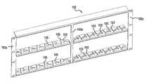
- FIG. 1is a perspective view of the high-density multi-port-module patch panel system 100 in accordance with one embodiment of the present invention.
- the high-density multi-port-module patch panel system 100comprises a rack 112 having a first or right rail 112 a and a second or left rail 112 b and a patch panel frame 102 mounted on the rack 112 .
- the patch panel frame 102includes the first plurality of vertical multi-port modules 104 and the second plurality of vertical multi-port modules 106 .
- the multi-port modules 104 and 106could be horizontal multi-port modules.
- the patch panel frame 102has a front face 102 a , which resides in a plane that is substantially parallel with a plane defined by the right rail 112 a and the left rail 112 b of the rack 112 .
- the patch panel frame 102is a two-tier patch panel frame, i.e., the frame includes two rows of multi-port modules 104 and 106 .
- the patch panel frame 102could be a one-tier patch panel frame (i.e., only one row of multi-port modules 104 and 106 ) to accommodate less modules.
- the patch panel frame 102could have more than two rows of multi-port modules 104 and 106 .
- the framemay have room for two or more rows of multi-port modules that only one row may be populated. One or more rows may be left empty and accommodate further expansion when additional multi-ports are required.
- the high-density multi-port-module patch panel system 100also comprises a first vertical cable manager 108 on the right rail 112 a of the rack 112 and a second vertical cable manager 110 on the left rail 112 b of the rack 112 .
- the first and the second vertical cable managers 108 and 110hold cables 114 connected to the first and the second plurality of multi-port modules 104 and 106 , respectively.
- the vertical cable managersare 4-inch CPI cable distribution spools. If only a one-tier patch panel frame (i.e., only one row of multi-port modules) is mounted on the rack 112 , one spool on each side of the rack 112 would be enough to hold the cables 114 . In a two-tier patch panel frame, two spools on each side of the rack 112 are preferred to avoid overloading of cables on an individual spool.
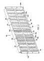
- FIG. 2is a close-up perspective view of the high-density patch panel with multi-port modules of FIG. 1 , removed from the rack 112 .
- the patch panel frame 102is made of a lightweight steel sheet, and the patch panel frame 102 includes a steel vertical reinforcement bar 102 b to provide stiffening and structural integrity.
- the first plurality of multi-port modules 104are juxtaposed in the patch panel frame 102 to the right of the reinforcement bar 102 b .
- the ports of the first plurality of multi-port modules 104are directed at a first angle, relative to a normal line extending away from the front face 102 a , toward the right rail 112 a of the rack 112 .
- the second plurality of multi-port modules 106are juxtaposed in the patch panel frame 102 to the left of the reinforcement bar 102 b .
- the ports of the second plurality of multi-port modules 106are directed at a second angle, relative to a normal line extending away from the front face 102 a , toward the left rail 112 b of the rack 112 .
- the portsmay be directed at the first or second angle by angling the modules 104 or 106 , or by having the ports formed at an angle within the module 104 or 106 .
- the multi-port modules 104 and 106could be horizontal multi-port modules, wherein the ports are angled at the first or second angle.
- the first angleranges from approximately ten degrees to approximately forty-five degrees.
- the second anglealso ranges from approximately ten degrees to approximately forty-five degrees.
- the first and second anglesare preferably the same. However, the first and second angles can be different based on the individual applications of the present invention. In the embodiment shown in FIG. 2 , the first angle and the second angle are approximately twenty degrees and are symmetrical to a normal line, which extends away from the front face 102 a of the patch panel frame 102 at ninety degrees.
- the first plurality of multi-port modules 104are positioned on the right side of the patch panel frame 102 adjacent to the first cable manager 108 .
- the second plurality of multi-port modules 106are positioned on the left side of the patch panel frame 102 adjacent to the second cable manager 110 .
- the first plurality of multi-port modules 104 and the second plurality of multi-port modules 106are illustrated as being juxtaposed in the patch panel frame, but may be slightly spaced apart in their adjacent state.
- each of the multi-port moduleshas a ridge 104 a or 106 a .
- a plane defined by the ridges 104 a and a plane defined by the ridges 106 aare parallel to the front face 102 a of the patch panel frame 102 .
- the angled modules 104 and 106exert less stress on the jacks and the portions of the cables 114 near the jacks, as compared to cables 114 connected to the modules at ninety degrees relative to the frame 102 . Furthermore, the angled arrangement makes the technician's job easier to manage the cables, because the existing cables do not block the labels 200 on the modules, the technician can easily identify a specific cable and plug or unplug a cable into the identified port, without removing other cables.
- the first and second plurality of multi-port modules 104 and 106are standard “1100 series” modules, which have six ports.
- the present inventioncan be used in conjunction with other known or custom designed multi-port modules.
- the first and second modulesdo not have to be the same type of modules. It is within the scope of the invention to employ different types of modules for the first and second modules based upon the user's needs.
- the patch panel frame 102can accommodate twenty-eight of the “1100 series” type modules, each of which has six ports; i.e., there is a one hundred and sixty eight port capacity for cable connection in a 5 U sized patch panel frame. This would provide a 33.6 ports per U density. Such a 33.6 ports per U density is a higher density, as compared to conventional designs. Further, this higher density layout is accomplished in an environment, which provides improved strain relief on the connectors, better visibility of labeling, and a neater appearance.
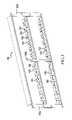
- FIG. 3is a perspective view of the frame of the high-density patch panel of FIG. 2 .
- the patch panel frame 102comprises slots 103 configured at the first angle, and slots 105 configured at the second angle to accommodate the first and the second plurality of multi-port modules 104 and 106 , respectively.
- the slots 103are configured to allow only one-way insertion of the multi-port modules 104 and 106 .
- the slots 103 and 105lock the first and the second plurality of multi-port modules 104 and 106 , after the first and the second plurality of multi-port modules 104 and 106 are engaged in the slots 103 and 105 .
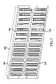
- FIG. 4is a back view of the high-density multi-port-module patch panel of FIG. 2 .
- the backs of the multi-port modules 104 and 106include connectors for connection to wires, which are in turn connected to various system devices (not shown), such as devices associated with a network system, a telephone exchange system, etc.
- the connection of wires to the backs of the modulesmay be accomplished by wire wrapping of terminals, or insulation displacement connectors (IDCs) or any other type of connectors.
- IDCsinsulation displacement connectors
- FIG. 5is a perspective view of the high-density patch panel frame 202 employing fiber optics modules 204 and 206 , in accordance with another embodiment of the present invention.
- the high-density patch panel system of the present inventionprovides a higher port density than conventional patch panel systems because additional space for the horizontal cable manager is not required in the present invention.
- the present inventionalso effectively reduces the stress imposed on the cables and connectors adjacent to jacks, and facilitates the technician's management and maintenance.
Landscapes
- Engineering & Computer Science (AREA)
- Computer Networks & Wireless Communication (AREA)
- Structure Of Telephone Exchanges (AREA)
Abstract
Description
Claims (23)
Priority Applications (4)
| Application Number | Priority Date | Filing Date | Title |
|---|---|---|---|
| US10/791,812US6974348B2 (en) | 2004-03-04 | 2004-03-04 | High-density multi-port-module patch panel system |
| PCT/US2005/006928WO2005091030A1 (en) | 2004-03-04 | 2005-03-04 | A high-density multi-port-module patch panel system |
| MXPA06009961AMXPA06009961A (en) | 2004-03-04 | 2005-03-04 | A high-density multi-port-module patch panel system. |
| CA002557880ACA2557880A1 (en) | 2004-03-04 | 2005-03-04 | A high-density multi-port-module patch panel system |
Applications Claiming Priority (1)
| Application Number | Priority Date | Filing Date | Title |
|---|---|---|---|
| US10/791,812US6974348B2 (en) | 2004-03-04 | 2004-03-04 | High-density multi-port-module patch panel system |
Publications (2)
| Publication Number | Publication Date |
|---|---|
| US20050197005A1 US20050197005A1 (en) | 2005-09-08 |
| US6974348B2true US6974348B2 (en) | 2005-12-13 |
Family
ID=34911712
Family Applications (1)
| Application Number | Title | Priority Date | Filing Date |
|---|---|---|---|
| US10/791,812Expired - Fee RelatedUS6974348B2 (en) | 2004-03-04 | 2004-03-04 | High-density multi-port-module patch panel system |
Country Status (4)
| Country | Link |
|---|---|
| US (1) | US6974348B2 (en) |
| CA (1) | CA2557880A1 (en) |
| MX (1) | MXPA06009961A (en) |
| WO (1) | WO2005091030A1 (en) |
Cited By (19)
| Publication number | Priority date | Publication date | Assignee | Title |
|---|---|---|---|---|
| US20060013437A1 (en)* | 2004-06-22 | 2006-01-19 | David Nister | Method and apparatus for determining camera pose |
| US7278880B1 (en)* | 2006-03-31 | 2007-10-09 | Hsing Chau Industrial Co., Ltd. | Jumper board |
| US20080002937A1 (en)* | 2006-06-29 | 2008-01-03 | Gordon Spisany | Patch panels with communications connectors that are rotatable about a vertical axis |
| USD559186S1 (en)* | 2004-09-20 | 2008-01-08 | Rit Technologies Ltd. | High-density patch panel |
| US20080089656A1 (en)* | 2006-10-11 | 2008-04-17 | Panduit Corp. | Release Latch for Pre-Terminated Cassette |
| US20080146079A1 (en)* | 2006-12-13 | 2008-06-19 | Commscope Solutions Properties | Fixed angled patch panel |
| US20090163043A1 (en)* | 2007-12-21 | 2009-06-25 | Yannick Demers | Patch panel with angled module |
| US20090226181A1 (en)* | 2008-02-13 | 2009-09-10 | Fiber Connections Inc. | Digital signal media conversion panel |
| US20100296789A1 (en)* | 2009-05-22 | 2010-11-25 | Wade Womack | Telecommunications patching system with cable management system and related cable management equipment |
| US20140103790A1 (en)* | 2011-05-18 | 2014-04-17 | Dirtt Environmental Solutions, Ltd. | Cable consolidation boxes and systems |
| US20150370028A1 (en)* | 2010-06-02 | 2015-12-24 | Tyco Electronics Corporation | Switch rack system |
| US9270098B2 (en) | 2011-12-14 | 2016-02-23 | Dirtt Environmental Solutions, Ltd | Service cable box |
| US9864158B2 (en) | 2014-09-12 | 2018-01-09 | Panduit Corp. | High density fiber enclosure and method |
| US9885845B2 (en)* | 2015-01-15 | 2018-02-06 | Commscope, Inc. Of North Carolina | Module and assembly for fiber optic interconnections |
| US9910236B2 (en) | 2008-08-29 | 2018-03-06 | Corning Optical Communications LLC | High density and bandwidth fiber optic apparatuses and related equipment and methods |
| US10094996B2 (en) | 2008-08-29 | 2018-10-09 | Corning Optical Communications, Llc | Independently translatable modules and fiber optic equipment trays in fiber optic equipment |
| US11294136B2 (en) | 2008-08-29 | 2022-04-05 | Corning Optical Communications LLC | High density and bandwidth fiber optic apparatuses and related equipment and methods |
| WO2023230089A1 (en) | 2022-05-26 | 2023-11-30 | Commscope Technologies Llc | Recessed power cable transition panel |
| USD1073626S1 (en) | 2022-10-31 | 2025-05-06 | Commscope Technologies Llc | Recessed power cable transition panel |
Families Citing this family (11)
| Publication number | Priority date | Publication date | Assignee | Title |
|---|---|---|---|---|
| TWM267653U (en)* | 2004-10-26 | 2005-06-11 | Quanta Comp Inc | Connector assembly |
| GB2451385A (en)* | 2006-06-29 | 2009-01-28 | Commscope Inc | Patch panels with communications connectors that are rotatable about a vertical axis |
| US7817444B2 (en) | 2006-11-30 | 2010-10-19 | Adc Gmbh | Detachable cable manager |
| AU312804S (en) | 2006-11-30 | 2007-02-07 | Tyco Electronics Services Gmbh | Detachable cable manager |
| US20080175159A1 (en)* | 2006-12-13 | 2008-07-24 | Panduit Corp. | High Performance Three-Port Switch for Managed Ethernet Systems |
| GB2451849A (en)* | 2007-08-14 | 2009-02-18 | Brand Rex Ltd | Patch panel having angled jacks |
| US7856166B2 (en)* | 2008-09-02 | 2010-12-21 | Corning Cable Systems Llc | High-density patch-panel assemblies for optical fiber telecommunications |
| US7672561B1 (en)* | 2008-10-02 | 2010-03-02 | Commscope, Inc. Of North Carolina | Telecommunications patching system with patching modules |
| US20110103575A1 (en)* | 2009-10-30 | 2011-05-05 | Telect Inc. | High-density splitter/patch telecommunications system |
| US8585437B2 (en)* | 2011-11-10 | 2013-11-19 | Jyh Eng Technology Co., Ltd. | Angle panel |
| US11411377B2 (en)* | 2020-01-10 | 2022-08-09 | Commscope Technologies Llc | Connection interface |
Citations (5)
| Publication number | Priority date | Publication date | Assignee | Title |
|---|---|---|---|---|
| US4824196A (en)* | 1987-05-26 | 1989-04-25 | Minnesota Mining And Manufacturing Company | Optical fiber distribution panel |
| US5011257A (en)* | 1988-06-29 | 1991-04-30 | British Telecommunications Public Limited Company | Optical fiber patch panel |
| US5127082A (en)* | 1991-03-22 | 1992-06-30 | The Siemon Company | Fiber optic patch panel |
| US6424781B1 (en)* | 1999-03-01 | 2002-07-23 | Adc Telecommunications, Inc. | Optical fiber distribution frame with pivoting connector panels |
| US6761585B2 (en)* | 2001-11-16 | 2004-07-13 | Adc Telecommunications, Inc. | Angled RJ to RJ patch panel |
- 2004
- 2004-03-04USUS10/791,812patent/US6974348B2/ennot_activeExpired - Fee Related
- 2005
- 2005-03-04WOPCT/US2005/006928patent/WO2005091030A1/enactiveApplication Filing
- 2005-03-04MXMXPA06009961Apatent/MXPA06009961A/enactiveIP Right Grant
- 2005-03-04CACA002557880Apatent/CA2557880A1/ennot_activeAbandoned
Patent Citations (5)
| Publication number | Priority date | Publication date | Assignee | Title |
|---|---|---|---|---|
| US4824196A (en)* | 1987-05-26 | 1989-04-25 | Minnesota Mining And Manufacturing Company | Optical fiber distribution panel |
| US5011257A (en)* | 1988-06-29 | 1991-04-30 | British Telecommunications Public Limited Company | Optical fiber patch panel |
| US5127082A (en)* | 1991-03-22 | 1992-06-30 | The Siemon Company | Fiber optic patch panel |
| US6424781B1 (en)* | 1999-03-01 | 2002-07-23 | Adc Telecommunications, Inc. | Optical fiber distribution frame with pivoting connector panels |
| US6761585B2 (en)* | 2001-11-16 | 2004-07-13 | Adc Telecommunications, Inc. | Angled RJ to RJ patch panel |
Cited By (47)
| Publication number | Priority date | Publication date | Assignee | Title |
|---|---|---|---|---|
| US20060013437A1 (en)* | 2004-06-22 | 2006-01-19 | David Nister | Method and apparatus for determining camera pose |
| USD559186S1 (en)* | 2004-09-20 | 2008-01-08 | Rit Technologies Ltd. | High-density patch panel |
| US7278880B1 (en)* | 2006-03-31 | 2007-10-09 | Hsing Chau Industrial Co., Ltd. | Jumper board |
| US7529458B2 (en) | 2006-06-29 | 2009-05-05 | Commscope Solutions Properties, Llc | Patch panels with communications connectors that are rotatable about a vertical axis |
| US7343078B2 (en) | 2006-06-29 | 2008-03-11 | Commscope Solutions Properties, Llc | Patch panels with communications connectors that are rotatable about a vertical axis |
| US20080002937A1 (en)* | 2006-06-29 | 2008-01-03 | Gordon Spisany | Patch panels with communications connectors that are rotatable about a vertical axis |
| US20080089656A1 (en)* | 2006-10-11 | 2008-04-17 | Panduit Corp. | Release Latch for Pre-Terminated Cassette |
| US8346046B2 (en) | 2006-10-11 | 2013-01-01 | Panduit Corp. | Release latch for pre-terminated cassette |
| US7689089B2 (en) | 2006-10-11 | 2010-03-30 | Panduit Corp. | Release latch for pre-terminated cassette |
| US7962000B2 (en) | 2006-10-11 | 2011-06-14 | Panduit Corp. | Release latch for pre-terminated cassette |
| US20110229102A1 (en)* | 2006-10-11 | 2011-09-22 | Panduit Corp. | Release latch for pre-terminated cassette |
| US20080146079A1 (en)* | 2006-12-13 | 2008-06-19 | Commscope Solutions Properties | Fixed angled patch panel |
| US7488205B2 (en) | 2006-12-13 | 2009-02-10 | Commscope, Inc. Of North Carolina | Fixed angled patch panel |
| US20090163043A1 (en)* | 2007-12-21 | 2009-06-25 | Yannick Demers | Patch panel with angled module |
| US20090226181A1 (en)* | 2008-02-13 | 2009-09-10 | Fiber Connections Inc. | Digital signal media conversion panel |
| US7837397B2 (en)* | 2008-02-13 | 2010-11-23 | Fiber Connections Inc. | Digital signal media conversion panel |
| US10459184B2 (en) | 2008-08-29 | 2019-10-29 | Corning Optical Communications LLC | High density and bandwidth fiber optic apparatuses and related equipment and methods |
| US11086089B2 (en) | 2008-08-29 | 2021-08-10 | Corning Optical Communications LLC | High density and bandwidth fiber optic apparatuses and related equipment and methods |
| US12072545B2 (en) | 2008-08-29 | 2024-08-27 | Corning Optical Communications LLC | High density and bandwidth fiber optic apparatuses and related equipment and methods |
| US11754796B2 (en) | 2008-08-29 | 2023-09-12 | Corning Optical Communications LLC | Independently translatable modules and fiber optic equipment trays in fiber optic equipment |
| US11609396B2 (en) | 2008-08-29 | 2023-03-21 | Corning Optical Communications LLC | High density and bandwidth fiber optic apparatuses and related equipment and methods |
| US11294135B2 (en) | 2008-08-29 | 2022-04-05 | Corning Optical Communications LLC | High density and bandwidth fiber optic apparatuses and related equipment and methods |
| US11294136B2 (en) | 2008-08-29 | 2022-04-05 | Corning Optical Communications LLC | High density and bandwidth fiber optic apparatuses and related equipment and methods |
| US11092767B2 (en) | 2008-08-29 | 2021-08-17 | Corning Optical Communications LLC | High density and bandwidth fiber optic apparatuses and related equipment and methods |
| US10852499B2 (en) | 2008-08-29 | 2020-12-01 | Corning Optical Communications LLC | High density and bandwidth fiber optic apparatuses and related equipment and methods |
| US9910236B2 (en) | 2008-08-29 | 2018-03-06 | Corning Optical Communications LLC | High density and bandwidth fiber optic apparatuses and related equipment and methods |
| US10094996B2 (en) | 2008-08-29 | 2018-10-09 | Corning Optical Communications, Llc | Independently translatable modules and fiber optic equipment trays in fiber optic equipment |
| US10120153B2 (en) | 2008-08-29 | 2018-11-06 | Corning Optical Communications, Llc | Independently translatable modules and fiber optic equipment trays in fiber optic equipment |
| US10126514B2 (en) | 2008-08-29 | 2018-11-13 | Corning Optical Communications, Llc | Independently translatable modules and fiber optic equipment trays in fiber optic equipment |
| US10222570B2 (en) | 2008-08-29 | 2019-03-05 | Corning Optical Communications LLC | Independently translatable modules and fiber optic equipment trays in fiber optic equipment |
| US10416405B2 (en) | 2008-08-29 | 2019-09-17 | Corning Optical Communications LLC | Independently translatable modules and fiber optic equipment trays in fiber optic equipment |
| US10422971B2 (en) | 2008-08-29 | 2019-09-24 | Corning Optical Communicatinos LLC | High density and bandwidth fiber optic apparatuses and related equipment and methods |
| US10444456B2 (en) | 2008-08-29 | 2019-10-15 | Corning Optical Communications LLC | High density and bandwidth fiber optic apparatuses and related equipment and methods |
| US10606014B2 (en) | 2008-08-29 | 2020-03-31 | Corning Optical Communications LLC | Independently translatable modules and fiber optic equipment trays in fiber optic equipment |
| US10564378B2 (en) | 2008-08-29 | 2020-02-18 | Corning Optical Communications LLC | High density and bandwidth fiber optic apparatuses and related equipment and methods |
| US20100296789A1 (en)* | 2009-05-22 | 2010-11-25 | Wade Womack | Telecommunications patching system with cable management system and related cable management equipment |
| US8744228B2 (en) | 2009-05-22 | 2014-06-03 | Commscope, Inc. Of North Carolina | Telecommunications patching system with cable management system and related cable management equipment |
| US9632272B2 (en)* | 2010-06-02 | 2017-04-25 | Commscope Technologies Llc | Switch rack system |
| US20150370028A1 (en)* | 2010-06-02 | 2015-12-24 | Tyco Electronics Corporation | Switch rack system |
| US20140103790A1 (en)* | 2011-05-18 | 2014-04-17 | Dirtt Environmental Solutions, Ltd. | Cable consolidation boxes and systems |
| US9059576B2 (en)* | 2011-05-18 | 2015-06-16 | Dirtt Environmental Solutions, Ltd. | Cable consolidation boxes and systems |
| US9270098B2 (en) | 2011-12-14 | 2016-02-23 | Dirtt Environmental Solutions, Ltd | Service cable box |
| US9864158B2 (en) | 2014-09-12 | 2018-01-09 | Panduit Corp. | High density fiber enclosure and method |
| US10613285B2 (en) | 2015-01-15 | 2020-04-07 | Commscope, Inc. Of North Carolina | Module and assembly for fiber optic interconnections |
| US9885845B2 (en)* | 2015-01-15 | 2018-02-06 | Commscope, Inc. Of North Carolina | Module and assembly for fiber optic interconnections |
| WO2023230089A1 (en) | 2022-05-26 | 2023-11-30 | Commscope Technologies Llc | Recessed power cable transition panel |
| USD1073626S1 (en) | 2022-10-31 | 2025-05-06 | Commscope Technologies Llc | Recessed power cable transition panel |
Also Published As
| Publication number | Publication date |
|---|---|
| WO2005091030A1 (en) | 2005-09-29 |
| CA2557880A1 (en) | 2005-09-29 |
| MXPA06009961A (en) | 2007-03-21 |
| US20050197005A1 (en) | 2005-09-08 |
Similar Documents
| Publication | Publication Date | Title |
|---|---|---|
| US6974348B2 (en) | High-density multi-port-module patch panel system | |
| US10393980B2 (en) | Fiber distribution device | |
| US9971117B2 (en) | Rack cabling system | |
| US8238708B2 (en) | Fiber optic module | |
| US7343078B2 (en) | Patch panels with communications connectors that are rotatable about a vertical axis | |
| US7359610B2 (en) | Cable manager including nestable radius limiter | |
| US6866541B2 (en) | Angled patch panel with cable support bar for network cable racks | |
| US8005335B2 (en) | Fiber distribution hub with pigtail routing | |
| US20050142910A1 (en) | Angled patch panel assembly | |
| US20100316345A1 (en) | Fiber optic panel and method | |
| US20240345351A1 (en) | Pre-terminated cross-connect system | |
| US20240126026A1 (en) | High density fiber panel organization |
Legal Events
| Date | Code | Title | Description |
|---|---|---|---|
| AS | Assignment | Owner name:COMMSCOPE SOLUTIONS PROPERTIES, LLC., NEVADA Free format text:ASSIGNMENT OF ASSIGNORS INTEREST;ASSIGNOR:BENTLEY, DARRELL;REEL/FRAME:015048/0332 Effective date:20040226 | |
| AS | Assignment | Owner name:COMMSCOPE, INC. OF NORTH CAROLINA, NORTH CAROLINA Free format text:MERGER;ASSIGNOR:COMMSCOPE SOLUTIONS PROPERTIES, LLC;REEL/FRAME:019991/0643 Effective date:20061220 Owner name:COMMSCOPE, INC. OF NORTH CAROLINA,NORTH CAROLINA Free format text:MERGER;ASSIGNOR:COMMSCOPE SOLUTIONS PROPERTIES, LLC;REEL/FRAME:019991/0643 Effective date:20061220 | |
| AS | Assignment | Owner name:BANK OF AMERICA, N.A., AS ADMINISTRATIVE AGENT, CA Free format text:SECURITY AGREEMENT;ASSIGNORS:COMMSCOPE, INC. OF NORTH CAROLINA;ALLEN TELECOM, LLC;ANDREW CORPORATION;REEL/FRAME:020362/0241 Effective date:20071227 Owner name:BANK OF AMERICA, N.A., AS ADMINISTRATIVE AGENT,CAL Free format text:SECURITY AGREEMENT;ASSIGNORS:COMMSCOPE, INC. OF NORTH CAROLINA;ALLEN TELECOM, LLC;ANDREW CORPORATION;REEL/FRAME:020362/0241 Effective date:20071227 | |
| FPAY | Fee payment | Year of fee payment:4 | |
| AS | Assignment | Owner name:ANDREW LLC (F/K/A ANDREW CORPORATION), NORTH CAROL Free format text:PATENT RELEASE;ASSIGNOR:BANK OF AMERICA, N.A., AS ADMINISTRATIVE AGENT;REEL/FRAME:026039/0005 Effective date:20110114 Owner name:COMMSCOPE, INC. OF NORTH CAROLINA, NORTH CAROLINA Free format text:PATENT RELEASE;ASSIGNOR:BANK OF AMERICA, N.A., AS ADMINISTRATIVE AGENT;REEL/FRAME:026039/0005 Effective date:20110114 Owner name:ALLEN TELECOM LLC, NORTH CAROLINA Free format text:PATENT RELEASE;ASSIGNOR:BANK OF AMERICA, N.A., AS ADMINISTRATIVE AGENT;REEL/FRAME:026039/0005 Effective date:20110114 | |
| AS | Assignment | Owner name:JPMORGAN CHASE BANK, N.A., AS COLLATERAL AGENT, NE Free format text:SECURITY AGREEMENT;ASSIGNORS:ALLEN TELECOM LLC, A DELAWARE LLC;ANDREW LLC, A DELAWARE LLC;COMMSCOPE, INC. OF NORTH CAROLINA, A NORTH CAROLINA CORPORATION;REEL/FRAME:026276/0363 Effective date:20110114 | |
| AS | Assignment | Owner name:JPMORGAN CHASE BANK, N.A., AS COLLATERAL AGENT, NE Free format text:SECURITY AGREEMENT;ASSIGNORS:ALLEN TELECOM LLC, A DELAWARE LLC;ANDREW LLC, A DELAWARE LLC;COMMSCOPE, INC OF NORTH CAROLINA, A NORTH CAROLINA CORPORATION;REEL/FRAME:026272/0543 Effective date:20110114 | |
| REMI | Maintenance fee reminder mailed | ||
| LAPS | Lapse for failure to pay maintenance fees | ||
| STCH | Information on status: patent discontinuation | Free format text:PATENT EXPIRED DUE TO NONPAYMENT OF MAINTENANCE FEES UNDER 37 CFR 1.362 | |
| FP | Lapsed due to failure to pay maintenance fee | Effective date:20131213 | |
| AS | Assignment | Owner name:COMMSCOPE TECHNOLOGIES LLC, NORTH CAROLINA Free format text:RELEASE BY SECURED PARTY;ASSIGNOR:JPMORGAN CHASE BANK, N.A.;REEL/FRAME:048840/0001 Effective date:20190404 Owner name:COMMSCOPE, INC. OF NORTH CAROLINA, NORTH CAROLINA Free format text:RELEASE BY SECURED PARTY;ASSIGNOR:JPMORGAN CHASE BANK, N.A.;REEL/FRAME:048840/0001 Effective date:20190404 Owner name:ALLEN TELECOM LLC, ILLINOIS Free format text:RELEASE BY SECURED PARTY;ASSIGNOR:JPMORGAN CHASE BANK, N.A.;REEL/FRAME:048840/0001 Effective date:20190404 Owner name:REDWOOD SYSTEMS, INC., NORTH CAROLINA Free format text:RELEASE BY SECURED PARTY;ASSIGNOR:JPMORGAN CHASE BANK, N.A.;REEL/FRAME:048840/0001 Effective date:20190404 Owner name:ANDREW LLC, NORTH CAROLINA Free format text:RELEASE BY SECURED PARTY;ASSIGNOR:JPMORGAN CHASE BANK, N.A.;REEL/FRAME:048840/0001 Effective date:20190404 Owner name:COMMSCOPE TECHNOLOGIES LLC, NORTH CAROLINA Free format text:RELEASE BY SECURED PARTY;ASSIGNOR:JPMORGAN CHASE BANK, N.A.;REEL/FRAME:049260/0001 Effective date:20190404 Owner name:REDWOOD SYSTEMS, INC., NORTH CAROLINA Free format text:RELEASE BY SECURED PARTY;ASSIGNOR:JPMORGAN CHASE BANK, N.A.;REEL/FRAME:049260/0001 Effective date:20190404 Owner name:ALLEN TELECOM LLC, ILLINOIS Free format text:RELEASE BY SECURED PARTY;ASSIGNOR:JPMORGAN CHASE BANK, N.A.;REEL/FRAME:049260/0001 Effective date:20190404 Owner name:COMMSCOPE, INC. OF NORTH CAROLINA, NORTH CAROLINA Free format text:RELEASE BY SECURED PARTY;ASSIGNOR:JPMORGAN CHASE BANK, N.A.;REEL/FRAME:049260/0001 Effective date:20190404 Owner name:ANDREW LLC, NORTH CAROLINA Free format text:RELEASE BY SECURED PARTY;ASSIGNOR:JPMORGAN CHASE BANK, N.A.;REEL/FRAME:049260/0001 Effective date:20190404 |