US6974224B2 - Modularized light processing of body components - Google Patents
Modularized light processing of body componentsDownload PDFInfo
- Publication number
- US6974224B2 US6974224B2US10/632,542US63254203AUS6974224B2US 6974224 B2US6974224 B2US 6974224B2US 63254203 AUS63254203 AUS 63254203AUS 6974224 B2US6974224 B2US 6974224B2
- Authority
- US
- United States
- Prior art keywords
- light delivery
- light
- delivery module
- animal
- body component
- Prior art date
- Legal status (The legal status is an assumption and is not a legal conclusion. Google has not performed a legal analysis and makes no representation as to the accuracy of the status listed.)
- Expired - Fee Related, expires
Links
- 238000000034methodMethods0.000claimsabstractdescription38
- 238000001467acupunctureMethods0.000claimsabstractdescription19
- 241001465754MetazoaSpecies0.000claimsdescription37
- 230000007246mechanismEffects0.000claimsdescription21
- 239000003574free electronSubstances0.000claimsdescription14
- 238000003780insertionMethods0.000claimsdescription11
- 230000037431insertionEffects0.000claimsdescription11
- 238000005286illuminationMethods0.000claimsdescription10
- 230000035876healingEffects0.000claimsdescription9
- 210000002414legAnatomy0.000claimsdescription7
- 210000002683footAnatomy0.000claimsdescription6
- 210000003423ankleAnatomy0.000claimsdescription4
- 230000005672electromagnetic fieldEffects0.000claimsdescription4
- 210000000245forearmAnatomy0.000claimsdescription4
- 210000000689upper legAnatomy0.000claimsdescription4
- 210000000707wristAnatomy0.000claimsdescription4
- 238000011282treatmentMethods0.000abstractdescription18
- 238000001126phototherapyMethods0.000abstractdescription15
- 238000002560therapeutic procedureMethods0.000abstractdescription14
- 238000006243chemical reactionMethods0.000abstractdescription6
- 239000013589supplementSubstances0.000abstractdescription3
- 230000009286beneficial effectEffects0.000abstractdescription2
- 230000005855radiationEffects0.000description24
- 238000012360testing methodMethods0.000description22
- 210000003128headAnatomy0.000description17
- 230000009467reductionEffects0.000description11
- 230000000694effectsEffects0.000description10
- 102000002265Human Growth HormoneHuman genes0.000description8
- 108010000521Human Growth HormoneProteins0.000description8
- 239000000854Human Growth HormoneSubstances0.000description8
- RWSXRVCMGQZWBV-WDSKDSINSA-NglutathioneChemical compoundOC(=O)[C@@H](N)CCC(=O)N[C@@H](CS)C(=O)NCC(O)=ORWSXRVCMGQZWBV-WDSKDSINSA-N0.000description8
- 210000003491skinAnatomy0.000description8
- 210000001519tissueAnatomy0.000description8
- 210000001508eyeAnatomy0.000description7
- 238000004519manufacturing processMethods0.000description6
- 239000000463materialSubstances0.000description6
- 230000008929regenerationEffects0.000description6
- 238000011069regeneration methodMethods0.000description6
- 230000004913activationEffects0.000description5
- 230000008569processEffects0.000description5
- 150000003254radicalsChemical class0.000description5
- 230000035882stressEffects0.000description5
- 108010024636GlutathioneProteins0.000description4
- 230000001919adrenal effectEffects0.000description4
- 230000008901benefitEffects0.000description4
- 210000004027cellAnatomy0.000description4
- 229960003180glutathioneDrugs0.000description4
- 235000003969glutathioneNutrition0.000description4
- JYGXADMDTFJGBT-VWUMJDOOSA-NhydrocortisoneChemical compoundO=C1CC[C@]2(C)[C@H]3[C@@H](O)C[C@](C)([C@@](CC4)(O)C(=O)CO)[C@@H]4[C@@H]3CCC2=C1JYGXADMDTFJGBT-VWUMJDOOSA-N0.000description4
- 210000000987immune systemAnatomy0.000description4
- 230000006872improvementEffects0.000description4
- 230000002093peripheral effectEffects0.000description4
- 230000000638stimulationEffects0.000description4
- 230000032258transportEffects0.000description4
- ZKHQWZAMYRWXGA-KQYNXXCUSA-JATP(4-)Chemical compoundC1=NC=2C(N)=NC=NC=2N1[C@@H]1O[C@H](COP([O-])(=O)OP([O-])(=O)OP([O-])([O-])=O)[C@@H](O)[C@H]1OZKHQWZAMYRWXGA-KQYNXXCUSA-J0.000description3
- ZKHQWZAMYRWXGA-UHFFFAOYSA-NAdenosine triphosphateNatural productsC1=NC=2C(N)=NC=NC=2N1C1OC(COP(O)(=O)OP(O)(=O)OP(O)(O)=O)C(O)C1OZKHQWZAMYRWXGA-UHFFFAOYSA-N0.000description3
- 206010007733Catabolic stateDiseases0.000description3
- 238000010521absorption reactionMethods0.000description3
- 239000003963antioxidant agentSubstances0.000description3
- 235000006708antioxidantsNutrition0.000description3
- 208000037265diseases, disorders, signs and symptomsDiseases0.000description3
- 210000004209hairAnatomy0.000description3
- 230000031700light absorptionEffects0.000description3
- 238000012423maintenanceMethods0.000description3
- 230000003287optical effectEffects0.000description3
- 210000000056organAnatomy0.000description3
- 230000003068static effectEffects0.000description3
- GVJHHUAWPYXKBD-UHFFFAOYSA-N(±)-α-TocopherolChemical compoundOC1=C(C)C(C)=C2OC(CCCC(C)CCCC(C)CCCC(C)C)(C)CCC2=C1CGVJHHUAWPYXKBD-UHFFFAOYSA-N0.000description2
- 230000002407ATP formationEffects0.000description2
- CIWBSHSKHKDKBQ-JLAZNSOCSA-NAscorbic acidChemical compoundOC[C@H](O)[C@H]1OC(=O)C(O)=C1OCIWBSHSKHKDKBQ-JLAZNSOCSA-N0.000description2
- 108090000790EnzymesProteins0.000description2
- 102000004190EnzymesHuman genes0.000description2
- MHAJPDPJQMAIIY-UHFFFAOYSA-NHydrogen peroxideChemical compoundOOMHAJPDPJQMAIIY-UHFFFAOYSA-N0.000description2
- YJPIGAIKUZMOQA-UHFFFAOYSA-NMelatoninNatural productsCOC1=CC=C2N(C(C)=O)C=C(CCN)C2=C1YJPIGAIKUZMOQA-UHFFFAOYSA-N0.000description2
- 230000003078antioxidant effectEffects0.000description2
- 230000015572biosynthetic processEffects0.000description2
- 230000036772blood pressureEffects0.000description2
- 230000019522cellular metabolic processEffects0.000description2
- 210000003850cellular structureAnatomy0.000description2
- 230000037326chronic stressEffects0.000description2
- 210000002808connective tissueAnatomy0.000description2
- 239000000470constituentSubstances0.000description2
- 238000010276constructionMethods0.000description2
- 239000002178crystalline materialSubstances0.000description2
- 230000009849deactivationEffects0.000description2
- 230000007423decreaseEffects0.000description2
- 206010012601diabetes mellitusDiseases0.000description2
- 201000010099diseaseDiseases0.000description2
- 238000009826distributionMethods0.000description2
- 210000005069earsAnatomy0.000description2
- 238000002474experimental methodMethods0.000description2
- 230000006870functionEffects0.000description2
- 230000012010growthEffects0.000description2
- 229960000890hydrocortisoneDrugs0.000description2
- 230000000968intestinal effectEffects0.000description2
- 229960003987melatoninDrugs0.000description2
- DRLFMBDRBRZALE-UHFFFAOYSA-NmelatoninChemical compoundCOC1=CC=C2NC=C(CCNC(C)=O)C2=C1DRLFMBDRBRZALE-UHFFFAOYSA-N0.000description2
- 239000012528membraneSubstances0.000description2
- 239000007769metal materialSubstances0.000description2
- 208000010125myocardial infarctionDiseases0.000description2
- 239000007800oxidant agentSubstances0.000description2
- 230000036542oxidative stressEffects0.000description2
- 238000011084recoveryMethods0.000description2
- 230000001105regulatory effectEffects0.000description2
- 230000010076replicationEffects0.000description2
- 230000033458reproductionEffects0.000description2
- 230000003248secreting effectEffects0.000description2
- 239000000126substanceSubstances0.000description2
- 210000001685thyroid glandAnatomy0.000description2
- 210000002700urineAnatomy0.000description2
- 208000002874Acne VulgarisDiseases0.000description1
- 102000009027AlbuminsHuman genes0.000description1
- 108010088751AlbuminsProteins0.000description1
- 208000024827Alzheimer diseaseDiseases0.000description1
- 206010003210ArteriosclerosisDiseases0.000description1
- 241000894006BacteriaSpecies0.000description1
- 208000024172Cardiovascular diseaseDiseases0.000description1
- 108010075016CeruloplasminProteins0.000description1
- 102100023321CeruloplasminHuman genes0.000description1
- 102000008186CollagenHuman genes0.000description1
- 108010035532CollagenProteins0.000description1
- ZZZCUOFIHGPKAK-UHFFFAOYSA-ND-erythro-ascorbic acidNatural productsOCC1OC(=O)C(O)=C1OZZZCUOFIHGPKAK-UHFFFAOYSA-N0.000description1
- 208000020401Depressive diseaseDiseases0.000description1
- 102000009025EndorphinsHuman genes0.000description1
- 108010049140EndorphinsProteins0.000description1
- 102000008857FerritinHuman genes0.000description1
- 108050000784FerritinProteins0.000description1
- 238000008416FerritinMethods0.000description1
- 208000004262Food HypersensitivityDiseases0.000description1
- 206010017533Fungal infectionDiseases0.000description1
- 241000233866FungiSpecies0.000description1
- 108010061711GliadinProteins0.000description1
- 102000001554HemoglobinsHuman genes0.000description1
- 108010054147HemoglobinsProteins0.000description1
- 208000001688Herpes GenitalisDiseases0.000description1
- 206010062767HypophysitisDiseases0.000description1
- 206010061218InflammationDiseases0.000description1
- 102000015696InterleukinsHuman genes0.000description1
- 108010063738InterleukinsProteins0.000description1
- 102000008072LymphokinesHuman genes0.000description1
- 108010074338LymphokinesProteins0.000description1
- 206010028980NeoplasmDiseases0.000description1
- 206010030113OedemaDiseases0.000description1
- 208000030852Parasitic diseaseDiseases0.000description1
- 206010057249PhagocytosisDiseases0.000description1
- 208000004210Pressure UlcerDiseases0.000description1
- 206010070834SensitisationDiseases0.000description1
- 208000014151Stomatognathic diseaseDiseases0.000description1
- 210000001744T-lymphocyteAnatomy0.000description1
- 210000000662T-lymphocyte subsetAnatomy0.000description1
- LEHOTFFKMJEONL-UHFFFAOYSA-NUric AcidChemical compoundN1C(=O)NC(=O)C2=C1NC(=O)N2LEHOTFFKMJEONL-UHFFFAOYSA-N0.000description1
- TVWHNULVHGKJHS-UHFFFAOYSA-NUric acidNatural productsN1C(=O)NC(=O)C2NC(=O)NC21TVWHNULVHGKJHS-UHFFFAOYSA-N0.000description1
- 229930003268Vitamin CNatural products0.000description1
- 229930003427Vitamin ENatural products0.000description1
- 206010052428WoundDiseases0.000description1
- 208000027418Wounds and injuryDiseases0.000description1
- 239000002253acidSubstances0.000description1
- 206010000496acneDiseases0.000description1
- 230000002730additional effectEffects0.000description1
- 230000010062adhesion mechanismEffects0.000description1
- 239000000853adhesiveSubstances0.000description1
- 230000001070adhesive effectEffects0.000description1
- 230000032683agingEffects0.000description1
- 229940050528albuminDrugs0.000description1
- 239000003513alkaliSubstances0.000description1
- OENHQHLEOONYIE-UKMVMLAPSA-Nall-trans beta-caroteneNatural productsCC=1CCCC(C)(C)C=1/C=C/C(/C)=C/C=C/C(/C)=C/C=C/C=C(C)C=CC=C(C)C=CC1=C(C)CCCC1(C)COENHQHLEOONYIE-UKMVMLAPSA-N0.000description1
- 230000000172allergic effectEffects0.000description1
- 230000001195anabolic effectEffects0.000description1
- 238000004458analytical methodMethods0.000description1
- 230000003466anti-cipated effectEffects0.000description1
- 238000013459approachMethods0.000description1
- 208000011775arteriosclerosis diseaseDiseases0.000description1
- 238000003556assayMethods0.000description1
- 208000006673asthmaDiseases0.000description1
- QVGXLLKOCUKJST-UHFFFAOYSA-Natomic oxygenChemical compound[O]QVGXLLKOCUKJST-UHFFFAOYSA-N0.000description1
- 208000010668atopic eczemaDiseases0.000description1
- 230000001580bacterial effectEffects0.000description1
- 235000013734beta-caroteneNutrition0.000description1
- TUPZEYHYWIEDIH-WAIFQNFQSA-Nbeta-caroteneNatural productsCC(=C/C=C/C=C(C)/C=C/C=C(C)/C=C/C1=C(C)CCCC1(C)C)C=CC=C(/C)C=CC2=CCCCC2(C)CTUPZEYHYWIEDIH-WAIFQNFQSA-N0.000description1
- 239000011648beta-caroteneSubstances0.000description1
- 229960002747betacaroteneDrugs0.000description1
- 230000008049biological agingEffects0.000description1
- 210000004369bloodAnatomy0.000description1
- 239000008280bloodSubstances0.000description1
- 238000004820blood countMethods0.000description1
- 201000011510cancerDiseases0.000description1
- 230000005800cardiovascular problemEffects0.000description1
- 230000003915cell functionEffects0.000description1
- 210000000170cell membraneAnatomy0.000description1
- 230000001413cellular effectEffects0.000description1
- 230000008859changeEffects0.000description1
- 230000001684chronic effectEffects0.000description1
- 229920001436collagenPolymers0.000description1
- 238000004891communicationMethods0.000description1
- 239000012141concentrateSubstances0.000description1
- 208000029078coronary artery diseaseDiseases0.000description1
- 239000002537cosmeticSubstances0.000description1
- 230000001186cumulative effectEffects0.000description1
- 230000006378damageEffects0.000description1
- 230000003247decreasing effectEffects0.000description1
- 230000002950deficientEffects0.000description1
- FMGSKLZLMKYGDP-USOAJAOKSA-NdehydroepiandrosteroneChemical compoundC1[C@@H](O)CC[C@]2(C)[C@H]3CC[C@](C)(C(CC4)=O)[C@@H]4[C@@H]3CC=C21FMGSKLZLMKYGDP-USOAJAOKSA-N0.000description1
- 208000002925dental cariesDiseases0.000description1
- 230000003831deregulationEffects0.000description1
- 230000035487diastolic blood pressureEffects0.000description1
- 230000037213dietEffects0.000description1
- 235000005911dietNutrition0.000description1
- 238000002845discolorationMethods0.000description1
- 208000035475disorderDiseases0.000description1
- 229940079593drugDrugs0.000description1
- 239000003814drugSubstances0.000description1
- 239000013013elastic materialSubstances0.000description1
- 230000005670electromagnetic radiationEffects0.000description1
- 230000002124endocrineEffects0.000description1
- 238000006911enzymatic reactionMethods0.000description1
- 210000003743erythrocyteAnatomy0.000description1
- 239000004744fabricSubstances0.000description1
- 239000000835fiberSubstances0.000description1
- 230000003328fibroblastic effectEffects0.000description1
- 230000005669field effectEffects0.000description1
- 235000020932food allergyNutrition0.000description1
- 210000001061foreheadAnatomy0.000description1
- 208000024386fungal infectious diseaseDiseases0.000description1
- WIGCFUFOHFEKBI-UHFFFAOYSA-Ngamma-tocopherolNatural productsCC(C)CCCC(C)CCCC(C)CCCC1CCC2C(C)C(O)C(C)C(C)C2O1WIGCFUFOHFEKBI-UHFFFAOYSA-N0.000description1
- 201000004946genital herpesDiseases0.000description1
- 230000002710gonadal effectEffects0.000description1
- 210000003780hair follicleAnatomy0.000description1
- 230000036541healthEffects0.000description1
- 208000014617hemorrhoidDiseases0.000description1
- 150000004680hydrogen peroxidesChemical class0.000description1
- 208000003669immune deficiency diseaseDiseases0.000description1
- 230000036737immune functionEffects0.000description1
- 230000036039immunityEffects0.000description1
- 208000015181infectious diseaseDiseases0.000description1
- 230000004054inflammatory processEffects0.000description1
- 238000011221initial treatmentMethods0.000description1
- 229910052500inorganic mineralInorganic materials0.000description1
- 230000002452interceptive effectEffects0.000description1
- 229940047122interleukinsDrugs0.000description1
- 230000001678irradiating effectEffects0.000description1
- 230000001788irregularEffects0.000description1
- 210000001847jawAnatomy0.000description1
- 238000002647laser therapyMethods0.000description1
- 230000021633leukocyte mediated immunityEffects0.000description1
- 230000003859lipid peroxidationEffects0.000description1
- 238000011418maintenance treatmentMethods0.000description1
- 230000002503metabolic effectEffects0.000description1
- 230000007102metabolic functionEffects0.000description1
- 230000004060metabolic processEffects0.000description1
- 239000002207metaboliteSubstances0.000description1
- 239000002184metalSubstances0.000description1
- 229910052751metalInorganic materials0.000description1
- 150000002739metalsChemical class0.000description1
- 239000011707mineralSubstances0.000description1
- 210000003470mitochondriaAnatomy0.000description1
- 210000001331noseAnatomy0.000description1
- 239000013307optical fiberSubstances0.000description1
- 239000001301oxygenSubstances0.000description1
- 229910052760oxygenInorganic materials0.000description1
- 210000001002parasympathetic nervous systemAnatomy0.000description1
- 230000008782phagocytosisEffects0.000description1
- 230000000886photobiologyEffects0.000description1
- 238000006303photolysis reactionMethods0.000description1
- 210000003635pituitary glandAnatomy0.000description1
- 230000003389potentiating effectEffects0.000description1
- 238000002203pretreatmentMethods0.000description1
- 230000002035prolonged effectEffects0.000description1
- 210000002307prostateAnatomy0.000description1
- 238000001243protein synthesisMethods0.000description1
- 102000004169proteins and genesHuman genes0.000description1
- 108090000623proteins and genesProteins0.000description1
- 230000018406regulation of metabolic processEffects0.000description1
- 230000008439repair processEffects0.000description1
- 208000017443reproductive system diseaseDiseases0.000description1
- 230000004044responseEffects0.000description1
- 210000003296salivaAnatomy0.000description1
- 210000004761scalpAnatomy0.000description1
- 231100000241scarToxicity0.000description1
- 208000012672seasonal affective diseaseDiseases0.000description1
- 230000028327secretionEffects0.000description1
- 230000008313sensitizationEffects0.000description1
- 238000001228spectrumMethods0.000description1
- 150000003431steroidsChemical class0.000description1
- 230000002195synergetic effectEffects0.000description1
- 238000003786synthesis reactionMethods0.000description1
- 230000035488systolic blood pressureEffects0.000description1
- FQZYTYWMLGAPFJ-OQKDUQJOSA-Ntamoxifen citrateChemical compound[H+].[H+].[H+].[O-]C(=O)CC(O)(CC([O-])=O)C([O-])=O.C=1C=CC=CC=1C(/CC)=C(C=1C=CC(OCCN(C)C)=CC=1)/C1=CC=CC=C1FQZYTYWMLGAPFJ-OQKDUQJOSA-N0.000description1
- 230000001225therapeutic effectEffects0.000description1
- 230000014616translationEffects0.000description1
- 229940116269uric acidDrugs0.000description1
- 230000002485urinary effectEffects0.000description1
- 230000003612virological effectEffects0.000description1
- 238000001429visible spectrumMethods0.000description1
- 235000019154vitamin CNutrition0.000description1
- 239000011718vitamin CSubstances0.000description1
- 235000019165vitamin ENutrition0.000description1
- 229940046009vitamin EDrugs0.000description1
- 239000011709vitamin ESubstances0.000description1
- OENHQHLEOONYIE-JLTXGRSLSA-Nβ-CaroteneChemical compoundCC=1CCCC(C)(C)C=1\C=C\C(\C)=C\C=C\C(\C)=C\C=C\C=C(/C)\C=C\C=C(/C)\C=C\C1=C(C)CCCC1(C)COENHQHLEOONYIE-JLTXGRSLSA-N0.000description1
Images


Classifications
- A—HUMAN NECESSITIES
- A61—MEDICAL OR VETERINARY SCIENCE; HYGIENE
- A61N—ELECTROTHERAPY; MAGNETOTHERAPY; RADIATION THERAPY; ULTRASOUND THERAPY
- A61N5/00—Radiation therapy
- A61N5/06—Radiation therapy using light
- A61N5/0613—Apparatus adapted for a specific treatment
- A61N5/0619—Acupuncture
- A—HUMAN NECESSITIES
- A61—MEDICAL OR VETERINARY SCIENCE; HYGIENE
- A61N—ELECTROTHERAPY; MAGNETOTHERAPY; RADIATION THERAPY; ULTRASOUND THERAPY
- A61N2/00—Magnetotherapy
- A61N2/002—Magnetotherapy in combination with another treatment
- A—HUMAN NECESSITIES
- A61—MEDICAL OR VETERINARY SCIENCE; HYGIENE
- A61N—ELECTROTHERAPY; MAGNETOTHERAPY; RADIATION THERAPY; ULTRASOUND THERAPY
- A61N5/00—Radiation therapy
- A61N5/06—Radiation therapy using light
- A61N5/0601—Apparatus for use inside the body
- A61N5/0603—Apparatus for use inside the body for treatment of body cavities
- A61N2005/0606—Mouth
- A—HUMAN NECESSITIES
- A61—MEDICAL OR VETERINARY SCIENCE; HYGIENE
- A61N—ELECTROTHERAPY; MAGNETOTHERAPY; RADIATION THERAPY; ULTRASOUND THERAPY
- A61N5/00—Radiation therapy
- A61N5/06—Radiation therapy using light
- A61N2005/0635—Radiation therapy using light characterised by the body area to be irradiated
- A61N2005/0643—Applicators, probes irradiating specific body areas in close proximity
- A61N2005/0645—Applicators worn by the patient
- A61N2005/0647—Applicators worn by the patient the applicator adapted to be worn on the head
- A—HUMAN NECESSITIES
- A61—MEDICAL OR VETERINARY SCIENCE; HYGIENE
- A61N—ELECTROTHERAPY; MAGNETOTHERAPY; RADIATION THERAPY; ULTRASOUND THERAPY
- A61N5/00—Radiation therapy
- A61N5/06—Radiation therapy using light
- A61N2005/065—Light sources therefor
- A61N2005/0651—Diodes
- A61N2005/0652—Arrays of diodes
- A—HUMAN NECESSITIES
- A61—MEDICAL OR VETERINARY SCIENCE; HYGIENE
- A61N—ELECTROTHERAPY; MAGNETOTHERAPY; RADIATION THERAPY; ULTRASOUND THERAPY
- A61N5/00—Radiation therapy
- A61N5/06—Radiation therapy using light
- A61N2005/0658—Radiation therapy using light characterised by the wavelength of light used
- A61N2005/0662—Visible light
- A61N2005/0663—Coloured light
Definitions
- This inventionrelates to illumination of a selected body component, or a few adjacent components, using light with selected wavelength ranges and selected illumination time intervals.
- Phototherapyinvolves generation of light by suitable light sources, such as light emitting diodes (LEDs) in the visible and infrared ranges to provide various benefits for a patient's body.
- LEDslight emitting diodes
- the photons producedare absorbed by the body through the skin, the eyes and acupuncture points or meridians.
- Connective tissues in the bodyconduct the light to deeper tissues and organs.
- suitable wavelengths of lightcan be delivered to, absorbed by and used by the body to activate metabolic functions.
- Treatment of a body using light irradiationrequires a choice of several important parameters, including wavelength range, relative distribution of the wavelengths within the range (spectrum), time interval for continuous exposure, time interval between two continuous exposures, time rate of energy delivered, accumulated energy density for exposures, body component(s) irradiated, and many others.
- the method and systemshould provide for, and distinguish between, initial treatments and maintenance treatments for a given medical condition and should cover a large number of, if not all of, conditions that are believed to be treatable using illumination.
- the inventionprovides application of radiation in selected wavelength ranges to a whole body, to a selected body component, or to a few adjacent body components, using a controlled sequence of exposures that illuminate the targeted body components. Any two consecutive time intervals of continuous radiation exposure are spaced apart by a “dark field” time interval whose length is at least equal to a threshold value, in order to re-establish a randomization of electron transport and distribution resulting from application of photons during a continuous exposure interval.
- Radiationis delivered to one or more selected (adjacent) body components, using an enhanced focussing system that increases the efficiency of delivery of the radiation.
- the radiation delivery systemcan be fitted or molded to preferentially illuminate only the desired body components.
- modulesincluding light delivery components that can be combined or used in stand-alone mode for delivery of light to part or all of the head, the interior of the mouth, one or more selected body parts and/or one or more selected acupuncture sites.
- Light therapy in or near the visible rangecan be combined with static or time-varying magnetic fields to provide additional effects and benefits.
- FIGS. 1-12schematically illustrate apparatus for delivery of radiation to selected (adjacent) body components according to embodiments of the invention.
- FIG. 13schematically illustrates a suitable pattern of light sources for different wavelengths.
- FIGS. 14A and 14Bgraphically illustrate time intervals for irradiation using different wavelength ranges according to two embodiments of the invention.
- FIGS. 15 , 16 and 17illustrate suitable light intensity patterns versus time for delivery of radiation according to the invention.
- FIG. 18is a representative graphical view of an average number of free electrons produced by an incident photon with a specified energy E.
- FIG. 19is a schematic view illustrating apparatus that can be used to practice the invention.
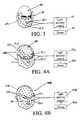
- FIG. 1illustrates a light delivery wrap system 11 suitable for generating and delivering radiation to one or more selected body components according to the invention.
- the system 11includes an electrical power source 13 that delivers controllable power to an assembly 15 of generators of electromagnetic radiation in the form of light in the visible and near infrared ranges (e.g., with wavelengths ⁇ in a range 400 nm ⁇ 1500 nm).
- the light generated by the radiation generator assembly 15also may have wavelengths in a near-ultraviolet range (e.g., 350 nm ⁇ 400 nm) and may have longer wavelengths in a mid-infrared range ( ⁇ >1500 nm), or in selected portions of one or more of these wavelength ranges.
- Each radiation generator in the assembly 15may be a laser, a light emitting diode, an intense incandescent light source, an intense fluorescent light source or any other suitable intense light source, or a combination of two or more such light sources.
- the radiation generator assembly 15is positioned on a light delivery wrap mechanism 16 that is configured to contact and wrap around a selected body component 19 , a group of two or more adjacent body components or the whole body, so that each radiation generator is spaced apart from the body component 19 by at least a selected threshold distance d(thr), to provide some control over the rate at which light is delivered to this body component.
- direct contact with the bodyis appropriate in some instances.
- one or more filters 17may be positioned between the radiation generator assembly 15 and the selected body component(s) 19 to be treated.
- the radiation generator assembly 15may produce a single or a few beams of light that are directed toward the body component 19 , considered as a target.
- the radiation generator assembly 15produces many light beams that are directed toward the body component 19 .
- the light beamsare produced in a pattern surrounding a selected body part, such as an arm or a leg, so that the selected body part and adjacent body parts are irradiated together in a (diffuse) field effect.
- the radiation generator assembly 15includes a timer 23 that activates and deactivates (turns on and turns off) the radiation generator during selected exposure time intervals, with any two consecutive continuous exposure (light) time intervals having a first selected length ⁇ t(exp), separated by a dark field time interval that has a second selected length ⁇ t(dark).
- This (light/dark/light) activity and its inverse (dark/light/dark)are sometimes referred to as a “reciprocating chase.”
- the first selected lengthlies in a preferred range 0.1 sec ⁇ t(exp) ⁇ 1 sec
- the second selected length ⁇ t(dark)is preferably between 0.1 sec and 1 sec.
- a light reflecting mechanism 25is positioned adjacent to the radiation generator assembly 15 to capture and direct light toward the selected body component 19 to couple some or all of the generated light that would otherwise have been lost into that body component.
- a light concentrator, condenser or other light focussing mechanism 21is positioned between the radiation generator assembly 15 and the body component 19 , to selectably concentrate (or to scatter within the body) the generated light on and around the body component 19 , the whole body or selected sites on the selected body component.
- the selected body component 19is a portion of, or all of, the head.
- the radiation generator assembly 15optionally includes a first assembly component 15 A that wraps around the chin, mouth and jaws of a patient, and optionally provides radiation within the patient's mouth, and a second assembly component 15 B that wraps around the upper jaws, nose, eyes, ears, forehead, upper neck and uppermost portion of the head of the patient.
- the first and second assembly components, 15 A and 15 Bcan be hooked together to form a unitary assembly 15 and can be disassembled into two or more components, such as 15 A and 15 B, to illuminate separate groups of body components.
- a flexible light delivery wrap 31is connected to the radiation generator 15 in FIG. 1 and is wrapped around (a portion of) a toe, a foot, an ankle, a leg, a thigh, a hip, a torso, a shoulder, an arm, an elbow, a forearm, a wrist, a hand, a finger, a neck and a top portion of a head or other body appendage of the patient.
- the light delivery wrap 31may be configured to enclose the entire body, or a substantial portion thereof. Preferably, this entire-body wrap does not enclose the patient's head, for which an independently controlled light delivery wrap, 41 and/or 51 (shown in FIGS. 3 and 4 ) is provided.
- FIG. 3illustrates a modular light delivery wrap 41 for a lower portion of a patient's head 43 .
- the light delivery wrap 41also includes a light delivery control module 47 and a suitable power supply 49 .
- the light delivery elements 45 - jcan be made individually activatable (on/off) and can be individually activated within one or more time intervals.
- a light delivery element 45 - j 1may be moved to a position within 1-10 cm of a portion of a patient's face that has a discoloration (e.g., based on a medical condition), the light delivery element can be rendered activatable, and the light delivery element can be activated (pulsed or continuous mode) for a sequence of selected time intervals, for example, 40 sec per minute with a 10-90 percent duty cycle.
- the wrap 41has also been used successfully for acne reduction, for scar reduction and for stress relief for one or more body components.
- FIG. 4Aillustrates a modular light delivery wrap 50 A that combines the lower portion light delivery wrap 41 shown in FIG. 3 with a second light delivery wrap 51 A that covers part or all of the upper portion of a patient's head 53 .
- the second light delivery wrap 51includes one or more apertures 52 A in the wrap for the patient's eyes so that an eye is not subjected to direct illumination by a light delivery element 55 - j .
- the light delivery wrap 50also includes a light delivery control module 57 and a suitable power supply 59 .
- adjustable light activation interval and dark field interval lengthse.g., 0.1-1 sec
- adjustable duty cyclese.g., 10-90 percent.
- FIG. 4Billustrates a one-piece light delivery system 50 B that covers most or all of the patient's face with a light delivery wrap 51 B.
- the light delivery wrap 51 Bincludes one or more of an eye aperture 52 B, a nose aperture 56 B, a mouth aperture and an ear aperture (not shown) so that an eye and/or nose and/or mouth and/or ear is not subjected to direct illumination by a light delivery element 55 - j .
- the light delivery system 50 Balso includes a light delivery control module 57 and a suitable power supply 59 .
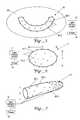
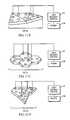
- FIG. 5illustrates a modular light delivery module 61 for the interior of a patient's mouth 63 .
- the light delivery module 61also includes a light delivery control module 67 and a suitable power supply 69 .
- the light delivery elements 65 - jcan be made individually activatable (on/off) and can be individually activated within one or more time intervals, as in the light delivery wrap 41 or 51 shown in FIG. 3 or FIGS. 4 A/ 4 B.
- the light delivery module 61can be placed adjacent to the patient's teeth and/or gums within the mouth 63 and activated one or more times within a time interval to suppress or eliminate the growth or presence of dental caries, root regeneration, loose teeth or other dental diseases, or the presence of diabetes.
- One or more light delivery elements 65 - jcan also be positioned near, and directed at, the roof of the patient's mouth 63 to irradiate and suppress growth of a bacterial or viral disease associated with the mouth interior, to support or boost the immune system, or to regenerate or maintain desirable reactions within the body.
- the light delivery module 61can be inserted into the mouth in a deflated condition, inflated for use on the mouth, then deflated for removal from the mouth.
- the light delivery module 61is flexible so that its shape can be molded or reformed to fit the shape of the mouth interior.
- the light delivery module 71may have any of a range of sizes.
- the light delivery module 71may be a prolate spheroid with a ⁇ 2 cm minimum diameter and b ⁇ 4 cm maximum diameter, which is slipped into and out of a patient's mouth.
- the light delivery module 71is optionally inserted into the mouth in a deflated condition, inflated for use in the mouth, then deflated for removal from the mouth.
- the light delivery module 81has a transverse diameter D (small or large) that is suitable for insertion of the module into the vaginal or urethral or other reproduction cavity of a female or male and is preferably arranged so that the module can be inserted in a deflated state and subsequently inflated by a suitable amount for therapy, then deflated for removal.
- the light delivery module 81is elastic and easily compressible to allow insertion and removal of the module in a partly compressed state.
- the light delivery module 81is suitable for treatment or reduction of female or male genital disorders, such as genital herpes, yeast infections, prostate problems, post-surgical stimulations, hemorrhoids and the like.
- most or all light delivery modules 85 - jare located at one end of the light delivery module 81 .
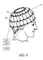
- the light delivery elements 95 - jare connected to a light delivery control module 97 and a suitable power supply 99 .
- the light delivery wrap 91is useful for treating disorders of the scalp, the hair follicles and/or the ears of a patient's head, and in performing photo-acupuncture at one or more head meridians.
- the hair net, head covering or hat 91 shown in FIG. 8can be reformed and extended, as an open format light delivery wrap, to be wrapped around a toe, a foot, an ankle, a leg, a thigh, a hip, a torso, a shoulder, an arm, an elbow, a forearm, a wrist, a hand, a finger, a neck or a portion of a head., to provide light therapy to a selected body part.
- the light delivery control module for the light delivery wrapsuch as the hair net 91 , can be arranged to be worn on the patient's waist or neck. This open format light delivery wrap can be worn inside the patient's clothes, if desired.
- the head covering 101is made of an elastic material so that a portion 103 of the covering can be stretched and positioned contiguous to the wearer's head, thereby irradiating adjacent regions of the wearer's head.
- the light delivery elements 105 - jare connected to a light delivery control module 107 and a suitable power supply 109 .
- the light delivery wrap 101can be worn for general living activities without interfering with those activities.
- back support and/or torso support for the useris provided for treatment and/or post-treatment recovery.
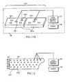
- FIG. 10illustrates a light delivery module 111 for placement on a portion of a patient's skin, as a substitute for, or supplement to, acupuncture treatment.
- the central light delivery element 115 Cmay deliver light in the same wavelength range(s) as is delivered by the peripheral light delivery modules 115 - j or may deliver light in one, two or more wavelength ranges that are different from the wavelength range(s) delivered by the peripheral light delivery elements 115 - j .
- the wavelength range for the central light delivery module 115 Cincludes at least a portion of the visible spectrum.
- the light delivery wrap 111also includes a light delivery control module 117 and a suitable power supply 119 .
- the central light delivery module 115 C in FIG. 10is preferably positioned at or adjacent to a known or suspected acupuncture point or meridian AP.
- the peripheral and/or central light delivery elements, 115 - j and/or 115 Care activated and deliver light in one or more selected wavelength ranges to the acupuncture meridian and surrounding tissues, to supplement or replace a conventional acupuncture treatment that uses needles.
- One advantage of replacement of conventional acupuncture treatment by light therapy, delivered to the same site(s),is that the patient's skin need not be mechanically punctured.
- Use of light therapy(1) avoids possible introduction of bacteria or other organisms at an acupuncture site, (2) avoids allergic and other similar reactions to the material (metals, etc.) used in acupuncture tools and (3) allows simultaneous delivery to multiple sites.
- the light delivery elements 115 - j in the light delivery module 111can be supplemented by one or more static or time-varying magnetic field sources 116 - j , as indicated in FIG. 10 ; the (peak) magnetic field strength can range from 100-10,000 Gauss, or higher if desired.
- a static and/or time-varying magnetic field having an associated frequency f1-10 4 Hz, or higher if desired, is optionally provided as part of the light-plus-magnetic field therapy.
- An acupuncture channelmay preferentially transport a magnetic field in somewhat the same manner that a light beam is believed to be preferentially transported by an acupuncture channel.
- the light delivery module 111can be “ganged” together with one or more additional, similar light delivery modules in a modularized approach to cover a surface region of the patient's body larger than can be covered by a single light delivery module.
- the light delivery control module 117 for two or more individual light delivery modulesare integrated so that a single light delivery control module 117 controls the light sequences and wavelengths and/or magnetic field frequencies f delivered by a group of two or more ganged-together light delivery modules 111 .
- Light therapymay also be applied in the form of a modular electronic or electromagnetic or photonic band-aid 121 , illustrated in FIGS. 11A-11D and 12 , and including one, two or more modular band-aid components, 122 - 1 , 122 - 2 , etc. that are optionally disposable.
- the band-aid 121may be applied to provide a “fast start” for a surface or sub-surface healing or other treatment process (e.g., for emergency use) or may be applied longer term as an integral part of a total healing process or for body component maintenance.
- the individual photonic band-aid components 122 - jare rectangular.
- FIGS. 11B , 11 C and 11 Dillustrate suitable other shapes for band-aid components, including regular triangles, regular hexagons and non-regular polygons. Two or more band-aid components or varying shapes can be used to cover a larger surface region or a surface region of irregular or unusual shape, or to replace a photonic band-aid component that is no longer operational.
- One or more of the light delivery elements 125 - j shown in FIG. 11Acan be supplemented with a magnetic field source, such as the magnetic field sources 116 - j shown in FIG. 10 .
- the associated power supply 129is preferably rechargeable so that the module 121 can be renewed by recharging the battery in place.
- a power supply 129is optionally provided with a first power supply module that is presently being used and a second, adjacent power supply module that is not presently being used and that can be recharged in parallel with present use of the first power supply module, without requiring removal of the photonic band-aid from service.
- FIG. 13illustrates a suitable light delivery pattern, in which selected light sources (e.g., light emitting diodes) deliver light in one, two, three or more selected wavelength ranges.
- selected light sourcese.g., light emitting diodes
- the preferred frequencies of application of the magnetic fieldare the following: (i) 1.7 Hz and/or 8 Hz (primarily for general stress reduction or relief); (ii) 4 Hz and/or 80 Hz (primarily for relief of sports-related stress); (iii) around 266 Hz (primarily for regeneration or cosmetic purposes); and/or (iv) other low frequencies suitable for stress relief, component regeneration and/or maintenance of beneficial chemical or physical reactions.
- the preferred frequencies of applicationare similar but further include a frequency of application around 666 Hz for regeneration. These treatments are normally applied for time intervals of 15-45 minutes but can be applied for shorter or longer time intervals as well.
- the light sources for the different wavelength rangesprovide light in different time intervals, with or without a dark field time interval imposed between two consecutive irradiation time intervals.
- FIG. 14Ais a graphical view of time intervals during which the first, second and third light sources (1), (2) and (3) are activated in a non-overlapping manner.
- Each light delivery elementmay deliver light in one or more selected wavelength ranges, when this element is activated, and adjacent light delivery elements may deliver the same, or different, wavelength ranges.
- LEDsLight emitting diodes
- Anticipated synergistic effects through substantially simultaneous application of two or more of these wavelengthsinclude the following: ______.
- HGHhuman growth hormone
- FIGS. 15 , 16 and 17illustrate representative light intensity patterns of light activation (exposure interval) and deactivation (dark field interval) that can be used for the individual light elements 35 ( i,j ) in FIG. 2 .
- the light intensity I(t;i;j)is (substantially) 0, then rises quickly to a maximum value I(max), then decreases monotonically to a lower value I(min) over an exposure time interval of length ⁇ t(exp), then goes to a (substantially) zero value for a dark field time interval of length ⁇ t(dark), then repeats this pattern at least once.
- the light intensity I(t;i;j)rises monotonically from a (substantially) zero value to a maximum value I(max), then falls quickly to a minimum or zero value I(min), over an exposure time interval of length ⁇ t(exp), then goes to a (substantially) zero value for a dark field time interval of length ⁇ t(dark), then repeats this pattern at least once.
- the light intensity I(t;i;j)rises to a first maximum value I(max; 1 ), optionally continues at or near that level for a first selected illumination time interval of length ⁇ t 1 , falls to a first lower value I(min; 1 ), goes to 0 for a dark field time interval of length ⁇ t(dark), rises to a second maximum value I(max; 2 ), optionally continues at that level for a second selected illumination time interval of length ⁇ t 1 , falls to a second lower value I(min; 2 ), then goes to 0.
- the maximum intensities I(max; 1 ) and I(max; 2 )may be the same or may differ, the minimum intensities I(min; 1 ) and I(min; 2 ) may be the same or may differ, and one or both of the minimum intensities I(min; 1 ) and I(min; 2 ) may be 0.
- Light intensity patterns other than those shown in FIGS. 14 , 15 and 16can be used.
- Each photon delivered to the vicinity of the body component 19is intended to produce one or more (preferably many) free electrons through photoelectric absorption and/or Compton scattering of the photon in its peregrinations through the body component and surrounding material.
- the photon energy Emust be at least a threshold value E(thr), which lies in a range of about 0.8-3.1 eV, depending upon the atomic and/or molecular constituents of the selected body component and surrounding material, in order to produce at least one free electron as the photon undergoes scattering within the body.
- a graph of average number N avg (E) of free electrons produced for a given incident photon energy Emight resemble the graph in FIG. 18 .
- This graphis similar to a graph of average number of free electrons produced by a photon incident on a metallic or crystalline material according to the Einstein model.
- Another important parameteris the rate r at which energy (or photons) is delivered to a unit area (e.g., over 1 cm 2 ) of body surface per unit time (e.g., in 1 sec), during an exposure time interval.
- energy density rates r in a range 0.0013 Joules/cm 2 /sec ⁇ r ⁇ 0.02 Joules/cm 2 /sec, averaged over a time interval of 5-45 minis an appropriate range for many body components. Delivery of energy at a rate lower than about 0.0013 Joules/cm 2 /sec will have some effect but will require much longer radiation application times than a typical application time of 5-45 min.
- the peak light intensity I(t;i;j), shown in the examples of FIGS. 13 , 14 and 15 ,will determine, or will be determined by, the energy rate r.
- FIG. 19schematically illustrates apparatus 150 that can be used to practice the invention for a patient's whole body, or parts thereof.
- a control panel 151controls the exposure time intervals, the dark field time intervals, the maximum intensity(ies), the particular intensity pattern(s) to be applied, the wavelength or frequency range(s) to be applied, target body component(s) and/or other relevant parameters, through control panel output signals delivered to a driver module 153 .
- the driver modulereceives timing signals from a timer module 154 and receives electrical power (preferably regulated power) from one or more voltage sources, 155 A and/or 155 B, that deliver voltage(s), V 1 and/or V 2 , or electrical current.
- At least one of the control panel 151 and the driver module 153includes a computer to process information and/or commands needed to provide appropriate light wavelengths in the appropriate time intervals according to the invention.
- the driver module 153delivers power to one or more of a left hand/arm exposure pad 157 - 1 , a left foot/leg exposure pad 159 - 1 , a right hand/arm exposure pad 157 - 2 , a right foot/leg exposure pad 159 - 2 a neck/shoulder(s)/back exposure pad 161 , and/or a light exposure canopy 163 covering part or all of a patient's body, each of which has an optional associated cumulative exposure monitor and/or exposure rate monitor connected to the corresponding exposure pad or exposure canopy.
- one or more of these exposure padsmay have its own electrical power supply, received directly from the driver module 153 .
- insertion of a dark field time interval between two consecutive continuous exposure time intervalsis useful in allowing the irradiated portion of the body to re-establish local equilibrium before the next pulse of photons arrives.
- the time interval required for re-establishing local equilibriumappears to vary from 0.1 sec to about 1 sec, depending upon variables such as the energy rate r, the accumulated energy E(accum) and the selected body component(s) irradiated. If the dark field time interval has a length less than a threshold value ⁇ t(dark) (including a situation where no dark field interval is present), the additional photons delivered may encounter a body environment that is not at or near equilibrium and that “channels” these photons in particular directions or into particular reaction channels, which is generally undesirable.
- the irradiated portion of the bodyis able to re-establish local equilibrium, or near-equilibrium, so that most or all photons within a given exposure time interval encounter substantially the same local environment, and a random or Monte Carlo type of photon scattering occurs within the next exposure time interval.
- the free electrons thus producedultimately come to equilibrium with the body component and adjacent material within the body, by attachment to a atom or molecule that can support attachment by another electron or by association with a assembly of substantially-free electrons that are weakly bound by the general electronic background of the local atomic and molecular constituents of the body.
- These equilibrated electronshave transferred substantially all their initial kinetic energy to one or more molecules in or adjacent to the body component, thus providing energy to promote certain healing processes in the body.
- Phototherapyis the application of light from an artificial light source to stimulate or promote one or more therapeutic effects in the body of an animal. such as a human being. Photons from the, light source are absorbed by the body through the skin, through the eyes and through acupuncture points or meridians. Light absorbed through one or more acupuncture points is believed to be transported especially efficiently along channels, referred to as biologically closed electrical paths or “meridians”, in the body, through a process similar to internal reflection of light in an optical fiber (whose refractive index is greater than the refractive index of the surrounding body material through which such a channel passes.
- These channelsare believed to be connective tissue protein fibers having specialized optical properties, including refractive indices ⁇ that are greater than the refractive indices ⁇ ′ of surrounding tissues, organs and other body material (wherein ⁇ ′(avg) ⁇ 1.4).
- Phototherapyactivates cell membranes within the body by increasing a membrane's natural electrical charge, sometimes referred to as “membrane capacitance.”
- a bodyis, in a sense, “charged” with photons, and the body's natural electromagnetic field (“biofield”) aids in organizing molecular structures in repair, regeneration and reproduction of cells and cell components and serves as a signal communication system in regulation of metabolic processes.
- the biofieldmay also serve as a power grid to provide electrical and/or chemical energy to drive and control biochemical and biophysical enzyme reactions that are part of a metabolic process.
- One such processis: (1) receipt and conversion of light in a channel; (2) activation of cell enzymes; and (3) enhanced production of adenosine triphosphate (ATP) from the activated enzymes, as the primary energy source for a body.
- ATPadenosine triphosphate
- Use of phototherapy to stimulate production and/or assimilation of human growth hormone (HGH) within the bodyis another attractive application.
- a GENOX oxidative stress testincluding 82 related assays that have some correlation with life expectancy, was performed initially (to provide a reference) and after the four-week therapy session. All test subjects showed increased ATP production.
- An Immune Panel 2was performed, measuring response of several immune functions to immune system stimulation. Interleukins and lymphokines, which regulate humeral and cell-mediated immune response, were improved, and numbers of T cell subsets increased, indicating improved T cell function.
- ASI testswere performed to measure hyper- and hypo-adrenocortisol states, deregulation of the hypothalmic pituitary gland adrenal axis and intestinal secretory IgA, and a gliadin antibody test was performed.
- the ASI testsprovide a measure of effects of chronic stress on organ reserve. Chronic stress often leads to a more catabolic state, with increased metabolic destruction. A significant reduction in cortisol, ranging from 23 to 81 percent, was found in the test subjects, indicating a reduction presence of the catabolic state.
- DHEA/cortisol ratioswere measured to evaluate the anabolic/catabolic state. Each test subject improved during the therapy session. Intestinal secretory IgA, which is a measure of mucosal immunity and has a low value where food allergies, chronic fungi and parasitic infections are present, was improved by 25 to 300 percent in the test subjects.
- a urinary free radical testwas performed to measure metabolites of lipid peroxidation in urine. Decreases of 33 to 66 percent in free radical generation were found in the test subjects, indicating a decreased likelihood of cardiovascular disease and stroke.
- HRVheart rate variability
- Aqueous hydrogen peroxide productionwas measured before the therapy session began and after the four-week session ended.
- Aqueous hydrogen peroxidesare free radical generators and oxidants used to fight infection and to support the immune system. A balance of oxidants and anti-oxidants is needed in the body. The test subjects consistently showed a significant reduction from pre-treatment levels, indicating the light therapy is not generating net gains in free radical populations.
- Glutathionered blood cell count and plasma were measured to evaluate anti-oxidant activity. Glutathione provides some of the most potent anti-oxidant reserves in the body. Levels of vitamin C, vitamin E, glutathione, beta-carotene, uric acid, albumin, ferritin, ceruloplasmin and transferin, which scavenge oxygen species of free radicals, were measured. Depletion of anti-oxidants is important in the ageing process and in associated diseases, such as arteriosclerosis, cancer, asthma, diabetes and immune deficiency diseases. The glutathione reserves continued to be regulated and were not depleted or interfered with during the therapy session.
Landscapes
- Health & Medical Sciences (AREA)
- Biomedical Technology (AREA)
- Engineering & Computer Science (AREA)
- Radiology & Medical Imaging (AREA)
- Pathology (AREA)
- Nuclear Medicine, Radiotherapy & Molecular Imaging (AREA)
- Pain & Pain Management (AREA)
- Life Sciences & Earth Sciences (AREA)
- Animal Behavior & Ethology (AREA)
- General Health & Medical Sciences (AREA)
- Public Health (AREA)
- Veterinary Medicine (AREA)
- Radiation-Therapy Devices (AREA)
Abstract
Description
Claims (52)
Priority Applications (4)
| Application Number | Priority Date | Filing Date | Title |
|---|---|---|---|
| US10/632,542US6974224B2 (en) | 2003-07-30 | 2003-07-30 | Modularized light processing of body components |
| EP04779211AEP1654492A4 (en) | 2003-07-30 | 2004-07-27 | Modularized light processing of body components |
| PCT/US2004/024040WO2005011801A2 (en) | 2003-07-30 | 2004-07-27 | Modularized light processing of body components |
| TW093122673ATW200510030A (en) | 2003-07-30 | 2004-07-29 | Modularized light processing of body components |
Applications Claiming Priority (1)
| Application Number | Priority Date | Filing Date | Title |
|---|---|---|---|
| US10/632,542US6974224B2 (en) | 2003-07-30 | 2003-07-30 | Modularized light processing of body components |
Publications (2)
| Publication Number | Publication Date |
|---|---|
| US20050024853A1 US20050024853A1 (en) | 2005-02-03 |
| US6974224B2true US6974224B2 (en) | 2005-12-13 |
Family
ID=34104411
Family Applications (1)
| Application Number | Title | Priority Date | Filing Date |
|---|---|---|---|
| US10/632,542Expired - Fee RelatedUS6974224B2 (en) | 2003-07-30 | 2003-07-30 | Modularized light processing of body components |
Country Status (4)
| Country | Link |
|---|---|
| US (1) | US6974224B2 (en) |
| EP (1) | EP1654492A4 (en) |
| TW (1) | TW200510030A (en) |
| WO (1) | WO2005011801A2 (en) |
Cited By (46)
| Publication number | Priority date | Publication date | Assignee | Title |
|---|---|---|---|---|
| US20050256552A1 (en)* | 2004-05-17 | 2005-11-17 | White Robert L | Toenail fungus eradicator |
| US20050261622A1 (en)* | 2003-09-17 | 2005-11-24 | Thomas Perez | Method and apparatus for providing light to blood |
| US20060200212A1 (en)* | 2005-02-17 | 2006-09-07 | Brawn Peter R | Light therapy device for treatment of bone disorders and biostimulation of bone and soft tissue |
| US20060223155A1 (en)* | 2002-11-01 | 2006-10-05 | Jackson Streeter | Enhancement of in vitro culture or vaccine production in bioreactors using electromagnetic energy |
| US20070248930A1 (en)* | 2005-02-17 | 2007-10-25 | Biolux Research Ltd. | Light therapy apparatus and methods |
| US7303578B2 (en) | 2001-11-01 | 2007-12-04 | Photothera, Inc. | Device and method for providing phototherapy to the brain |
| US20080281244A1 (en)* | 2007-05-10 | 2008-11-13 | Cisco Technology, Inc. | Electronic bandage with flexible electronic controller |
| US20090030489A1 (en)* | 2006-02-06 | 2009-01-29 | Koninklijke Philips Electronics N.V. | Body cover, glasses and/or at least partial head cover, method for radiating at least part of a human body and use of a body cover |
| US7575589B2 (en) | 2006-01-30 | 2009-08-18 | Photothera, Inc. | Light-emitting device and method for providing phototherapy to the brain |
| US20090234340A1 (en)* | 2008-03-11 | 2009-09-17 | Shaser, Inc. | Enhancing the emission spectrum of light-based dermatologic treatment devices |
| US20100061101A1 (en)* | 2007-04-17 | 2010-03-11 | Koninklijke Philips Electronics N.V. | Textile light emitting device |
| US7711430B2 (en) | 2006-02-10 | 2010-05-04 | Electrocore Llc | Methods and apparatus for treating anaphylaxis using electrical modulation |
| US7725188B2 (en) | 2006-02-10 | 2010-05-25 | Electrocore Llc | Electrical stimulation treatment of hypotension |
| US7747324B2 (en) | 2005-11-10 | 2010-06-29 | Electrocore Llc | Electrical stimulation treatment of bronchial constriction |
| US7848035B2 (en) | 2008-09-18 | 2010-12-07 | Photothera, Inc. | Single-use lens assembly |
| US8025687B2 (en) | 2003-01-24 | 2011-09-27 | Photothera, Inc. | Low level light therapy for enhancement of neurologic function |
| US8041428B2 (en) | 2006-02-10 | 2011-10-18 | Electrocore Llc | Electrical stimulation treatment of hypotension |
| US8088127B2 (en) | 2008-05-09 | 2012-01-03 | Innovative Pulmonary Solutions, Inc. | Systems, assemblies, and methods for treating a bronchial tree |
| US20120101342A1 (en)* | 2010-10-21 | 2012-04-26 | Duffy Thomas P | Pediatric tissue illuminator |
| US8172827B2 (en) | 2003-05-13 | 2012-05-08 | Innovative Pulmonary Solutions, Inc. | Apparatus for treating asthma using neurotoxin |
| US20120148975A1 (en)* | 2009-06-08 | 2012-06-14 | Biolux Research Ltd. | Method and apparatus for regulating tooth movement |
| US20120179228A1 (en)* | 2004-11-15 | 2012-07-12 | Decharms R Christopher | Applications of the stimulation of neural tissue using light |
| US8308784B2 (en) | 2006-08-24 | 2012-11-13 | Jackson Streeter | Low level light therapy for enhancement of neurologic function of a patient affected by Parkinson's disease |
| US20130029286A1 (en)* | 2010-02-04 | 2013-01-31 | Foster Thomas H | Devices and methods for conforming photodynamic therapy to specific anatomic locations |
| US8483831B1 (en) | 2008-02-15 | 2013-07-09 | Holaira, Inc. | System and method for bronchial dilation |
| DE102012005030A1 (en)* | 2012-03-12 | 2013-09-12 | Forschungszentrum Jülich GmbH | Apparatus and method for stimulating with thermo-stimuli |
| WO2013172859A1 (en)* | 2012-05-18 | 2013-11-21 | Photetica | Apparatus for maintaining treatment of peripheral neuropathy |
| US8740895B2 (en) | 2009-10-27 | 2014-06-03 | Holaira, Inc. | Delivery devices with coolable energy emitting assemblies |
| US8812112B2 (en) | 2005-11-10 | 2014-08-19 | ElectroCore, LLC | Electrical treatment of bronchial constriction |
| US8911439B2 (en) | 2009-11-11 | 2014-12-16 | Holaira, Inc. | Non-invasive and minimally invasive denervation methods and systems for performing the same |
| US9149328B2 (en) | 2009-11-11 | 2015-10-06 | Holaira, Inc. | Systems, apparatuses, and methods for treating tissue and controlling stenosis |
| US9242118B2 (en) | 2010-12-08 | 2016-01-26 | Biolux Research Ltd. | Methods useful for remodeling maxillofacial bone using light therapy and a functional appliance |
| US9398933B2 (en) | 2012-12-27 | 2016-07-26 | Holaira, Inc. | Methods for improving drug efficacy including a combination of drug administration and nerve modulation |
| US9622840B2 (en) | 2010-06-15 | 2017-04-18 | The Procter & Gamble Company | Methods for whitening teeth |
| US9730780B2 (en) | 2013-10-22 | 2017-08-15 | Biolux Research Ltd. | Intra-oral light-therapy apparatuses and methods for their use |
| US10315042B2 (en) | 2001-11-01 | 2019-06-11 | Pthera LLC | Device and method for providing a synergistic combination of phototherapy and a non-light energy modality to the brain |
| US10357662B2 (en) | 2009-02-19 | 2019-07-23 | Pthera LLC | Apparatus and method for irradiating a surface with light |
| US10695577B2 (en) | 2001-12-21 | 2020-06-30 | Photothera, Inc. | Device and method for providing phototherapy to the heart |
| US11273319B2 (en) | 2008-03-18 | 2022-03-15 | Pthera LLC | Method and apparatus for irradiating a surface with pulsed light |
| US20220257969A1 (en)* | 2008-07-01 | 2022-08-18 | Ralph Zipper | Method for treating pelvic pain, chronic prostatitis, and or overactive bladder symptoms |
| US20220273367A1 (en)* | 2008-07-01 | 2022-09-01 | Ralph Zipper | System and method for applying controlled dosage light therapy for treatment of body tissue |
| US11564863B2 (en) | 2020-06-29 | 2023-01-31 | Therabody, Inc. | Cooling attachment module for facial treatment device |
| US11730668B2 (en) | 2020-06-29 | 2023-08-22 | Therabody, Inc. | Vibrating therapy system and device |
| US11738207B2 (en) | 2021-04-08 | 2023-08-29 | Niraxx Light Therapeutics, Inc. | Photobiomodulation therapy garment, methods and uses |
| WO2024050266A1 (en) | 2022-09-02 | 2024-03-07 | Therabody, Inc. | Mask with vibration and light therapy |
| US11944840B2 (en) | 2021-04-08 | 2024-04-02 | Niraxx Light Therapeutics, Inc. | Photobiomodulation therapy garment, methods and uses |
Families Citing this family (37)
| Publication number | Priority date | Publication date | Assignee | Title |
|---|---|---|---|---|
| US7354433B2 (en)* | 2003-02-28 | 2008-04-08 | Advanced Light Technologies, Llc | Disinfection, destruction of neoplastic growth, and sterilization by differential absorption of electromagnetic energy |
| US20110040295A1 (en)* | 2003-02-28 | 2011-02-17 | Photometics, Inc. | Cancer treatment using selective photo-apoptosis |
| GB0414113D0 (en)* | 2004-06-24 | 2004-07-28 | Virulite Distrib Ltd | Cosmetic uses of electromagnetic radiation |
| EP1871476B1 (en) | 2005-03-31 | 2018-01-03 | Esther Mayer | Probe device for photobiomodulation of tissue lining a body cavity |
| AT503079B1 (en)* | 2005-04-29 | 2008-03-15 | Paris Lodron Uni Salzburg | DEVICE FOR IMPLEMENTING PHOTODYNAMIC TREATMENTS |
| GB0512038D0 (en)* | 2005-06-14 | 2005-07-20 | Dougal Gordon | Therapeutic and cosmetic uses of electromagnetic radiation |
| US20060287696A1 (en)* | 2005-06-21 | 2006-12-21 | Wright David W | Heat and light therapy treatment device and method |
| US8156398B2 (en)* | 2008-02-05 | 2012-04-10 | Anobit Technologies Ltd. | Parameter estimation based on error correction code parity check equations |
| US7924587B2 (en)* | 2008-02-21 | 2011-04-12 | Anobit Technologies Ltd. | Programming of analog memory cells using a single programming pulse per state transition |
| GB0812753D0 (en)* | 2008-07-14 | 2008-08-20 | Dougal Gordon R P | Electromagnetic radiation and its therapeutic effect |
| US20120046716A1 (en)* | 2009-04-13 | 2012-02-23 | Gordon Rex Paterson Dougal | Phototherapy Apparatus |
| DE102009048027A1 (en)* | 2009-10-02 | 2011-04-07 | Schäfer, Olaf | Method for the medical treatment of patients |
| ITTN20090013A1 (en)* | 2009-10-22 | 2011-04-23 | Gianfranco Bigaran | WIRELESS COMPUTERIZED SYSTEM (WIRELESS) FOR THE MULTIPLE APPLICATION OF LASERPUNTURE OR CHROMOPUNTURE TREATMENTS |
| EP2316405A1 (en)* | 2009-11-02 | 2011-05-04 | Tecnologica S.A.S. di Travaglini Cinzia & C. | Apparatus for stimulation of tissues, particularly for female erogenous zones |
| GB201005662D0 (en)* | 2010-04-06 | 2010-05-19 | Dougal Gordon R P | Phototherapeutic treatment of acne |
| KR20120018050A (en)* | 2010-08-20 | 2012-02-29 | 밍 후아 호 | Phototherapy |
| EP2646113A4 (en)* | 2010-12-03 | 2014-07-23 | Biolight Patent Holding Ab | .device for medical external treatment by light |
| KR102689597B1 (en)* | 2011-05-31 | 2024-07-29 | 클라렌슈 피티와이 리미티드 | Light therapy apparatuses |
| KR102090617B1 (en)* | 2011-05-31 | 2020-03-19 | 포토파믹스 인코포레이티드 | Light emitting apparatuses for treating and/or diagnosing motor related neurological conditions |
| JP6223328B2 (en)* | 2011-06-17 | 2017-11-01 | フィリップス ライティング ホールディング ビー ヴィ | Light emitting device and phototherapy device including light emitting device |
| CN104661706B (en)* | 2012-05-31 | 2018-11-06 | 弗托法米克斯股份有限公司 | A system for a subject with a motor-related neurological disorder |
| US9877361B2 (en)* | 2012-11-08 | 2018-01-23 | Applied Biophotonics Ltd | Phototherapy system and process including dynamic LED driver with programmable waveform |
| FR3018692B1 (en)* | 2014-03-24 | 2020-01-03 | Lucibel Sa | PORTABLE PHOTOTHERAPY TREATMENT MODULE. |
| CN107847755A (en)* | 2015-03-18 | 2018-03-27 | 考特尼投资公司 | Phototherapy apparatus |
| US12109429B2 (en) | 2015-07-28 | 2024-10-08 | Know Bio, Llc | Phototherapeutic light for treatment of pathogens |
| US11813476B1 (en)* | 2016-12-16 | 2023-11-14 | Erchonia Corporation, Llc | Methods of treating the brain and nervous system using light therapy |
| WO2018189393A1 (en)* | 2017-04-14 | 2018-10-18 | Regenlife | Transcutaneous irradiation device and application to the treatment of neurodegenerative diseases |
| KR102083509B1 (en)* | 2017-07-04 | 2020-03-04 | 심동희 | Apparatus for managing using could based platform of animal hospital management method for recognizing animal individual with based noseprint constructed with based it |
| US20200353273A1 (en)* | 2019-05-09 | 2020-11-12 | Doug Zucco | Method For Reducing Visceral Body Fat In Humans |
| CN114222606A (en)* | 2019-06-05 | 2022-03-22 | 生物前沿制药有限公司 | Illumination for photodynamic therapy |
| US11986666B2 (en) | 2020-03-19 | 2024-05-21 | Know Bio, Llc | Illumination devices for inducing biological effects |
| US11147984B2 (en) | 2020-03-19 | 2021-10-19 | Know Bio, Llc | Illumination devices for inducing biological effects |
| US12011611B2 (en) | 2020-03-19 | 2024-06-18 | Know Bio, Llc | Illumination devices for inducing biological effects |
| US11235169B1 (en) | 2020-10-15 | 2022-02-01 | Biofrontera Pharma Gmbh | Illumination device for photodynamic therapy, method for treating a skin disease and method for operating an illumination device |
| US12347337B2 (en) | 2020-12-10 | 2025-07-01 | Know Bio, Llc | Enhanced testing and characterization techniques for phototherapeutic light treatments |
| US12115384B2 (en)* | 2021-03-15 | 2024-10-15 | Know Bio, Llc | Devices and methods for illuminating tissue to induce biological effects |
| AU2022254047A1 (en)* | 2021-04-06 | 2023-11-02 | Shining Buddha Corp. | Wearable light therapy device |
Citations (10)
| Publication number | Priority date | Publication date | Assignee | Title |
|---|---|---|---|---|
| US4930504A (en) | 1987-11-13 | 1990-06-05 | Diamantopoulos Costas A | Device for biostimulation of tissue and method for treatment of tissue |
| US5312396A (en)* | 1990-09-06 | 1994-05-17 | Massachusetts Institute Of Technology | Pulsed laser system for the surgical removal of tissue |
| US5766233A (en) | 1994-01-20 | 1998-06-16 | Biolight Patent Holding Ab | Device for wound healing by means of light |
| US5800479A (en)* | 1994-01-20 | 1998-09-01 | Biolight Patent Holding Ab | Device for medical external treatment by means of light |
| US6063108A (en)* | 1997-01-06 | 2000-05-16 | Salansky; Norman | Method and apparatus for localized low energy photon therapy (LEPT) |
| US6238424B1 (en)* | 1996-06-07 | 2001-05-29 | Biolight Patent Holding Ab | Device for external treatment with pulsating light of high duty cycle |
| US6443978B1 (en) | 1998-04-10 | 2002-09-03 | Board Of Trustees Of The University Of Arkansas | Photomatrix device |
| US6454789B1 (en) | 1999-01-15 | 2002-09-24 | Light Science Corporation | Patient portable device for photodynamic therapy |
| US6482199B1 (en) | 1997-06-04 | 2002-11-19 | Joseph Neev | Method and apparatus for high precision variable rate material, removal and modification |
| US6524329B1 (en)* | 2001-03-08 | 2003-02-25 | Tru-Light Corporation | Body processing using light |
Family Cites Families (6)
| Publication number | Priority date | Publication date | Assignee | Title |
|---|---|---|---|---|
| DE8532628U1 (en)* | 1985-11-19 | 1986-04-17 | Elec Elektronische Bauteile und Geräte GmbH, 6209 Heidenrod | Combined magnetic field and infrared treatment device |
| US5616140A (en)* | 1994-03-21 | 1997-04-01 | Prescott; Marvin | Method and apparatus for therapeutic laser treatment |
| IT1285787B1 (en)* | 1994-03-29 | 1998-06-18 | Maef Srl | LED DIODE EQUIPMENT FOR CHROMOTHERAPY |
| GB2360459B (en)* | 2000-03-23 | 2002-08-07 | Photo Therapeutics Ltd | Therapeutic light source and method |
| US6602275B1 (en)* | 2000-09-18 | 2003-08-05 | Jana Sullivan | Device and method for therapeutic treatment of living organisms |
| US7107996B2 (en)* | 2001-04-10 | 2006-09-19 | Ganz Robert A | Apparatus and method for treating atherosclerotic vascular disease through light sterilization |
- 2003
- 2003-07-30USUS10/632,542patent/US6974224B2/ennot_activeExpired - Fee Related
- 2004
- 2004-07-27WOPCT/US2004/024040patent/WO2005011801A2/enactiveApplication Filing
- 2004-07-27EPEP04779211Apatent/EP1654492A4/ennot_activeWithdrawn
- 2004-07-29TWTW093122673Apatent/TW200510030A/enunknown
Patent Citations (10)
| Publication number | Priority date | Publication date | Assignee | Title |
|---|---|---|---|---|
| US4930504A (en) | 1987-11-13 | 1990-06-05 | Diamantopoulos Costas A | Device for biostimulation of tissue and method for treatment of tissue |
| US5312396A (en)* | 1990-09-06 | 1994-05-17 | Massachusetts Institute Of Technology | Pulsed laser system for the surgical removal of tissue |
| US5766233A (en) | 1994-01-20 | 1998-06-16 | Biolight Patent Holding Ab | Device for wound healing by means of light |
| US5800479A (en)* | 1994-01-20 | 1998-09-01 | Biolight Patent Holding Ab | Device for medical external treatment by means of light |
| US6238424B1 (en)* | 1996-06-07 | 2001-05-29 | Biolight Patent Holding Ab | Device for external treatment with pulsating light of high duty cycle |
| US6063108A (en)* | 1997-01-06 | 2000-05-16 | Salansky; Norman | Method and apparatus for localized low energy photon therapy (LEPT) |
| US6482199B1 (en) | 1997-06-04 | 2002-11-19 | Joseph Neev | Method and apparatus for high precision variable rate material, removal and modification |
| US6443978B1 (en) | 1998-04-10 | 2002-09-03 | Board Of Trustees Of The University Of Arkansas | Photomatrix device |
| US6454789B1 (en) | 1999-01-15 | 2002-09-24 | Light Science Corporation | Patient portable device for photodynamic therapy |
| US6524329B1 (en)* | 2001-03-08 | 2003-02-25 | Tru-Light Corporation | Body processing using light |
Non-Patent Citations (6)
| Title |
|---|
| Raum und Zeit, "Meridians Conduct Light", vol. 35, (88), 1991, pp. 16-18. |
| T. Karu, "Photobiology of Low-Power Laser Effects", Health Physics, vol. 56, No. 5, May 1989, pp. 691-705. |
| Text and drawings of application of U.S. Appl. No. 10/159,463. |
| Text and drawings of application of U.S. Appl. No. 10/370,330. |
| Textbook excerpt available at: www.amazon.com/gp/reader/9056991086/ref=sib_dp_pt/102-0788981-0683330#reader-link, "The Science of Low-Power Laser Therapy", Gordon and Breach, 1998. |
| Website printout: "Electro-Physiology, Light, and Facial Rejuvenation", 5 pages. |
Cited By (117)
| Publication number | Priority date | Publication date | Assignee | Title |
|---|---|---|---|---|
| US7303578B2 (en) | 2001-11-01 | 2007-12-04 | Photothera, Inc. | Device and method for providing phototherapy to the brain |
| US10315042B2 (en) | 2001-11-01 | 2019-06-11 | Pthera LLC | Device and method for providing a synergistic combination of phototherapy and a non-light energy modality to the brain |
| US10758743B2 (en) | 2001-11-01 | 2020-09-01 | Pthera LLC | Method for providing phototherapy to the brain |
| US10695577B2 (en) | 2001-12-21 | 2020-06-30 | Photothera, Inc. | Device and method for providing phototherapy to the heart |
| US20060223155A1 (en)* | 2002-11-01 | 2006-10-05 | Jackson Streeter | Enhancement of in vitro culture or vaccine production in bioreactors using electromagnetic energy |
| US7309348B2 (en)* | 2003-01-24 | 2007-12-18 | Photothera, Inc. | Method for treatment of depression |
| US8025687B2 (en) | 2003-01-24 | 2011-09-27 | Photothera, Inc. | Low level light therapy for enhancement of neurologic function |
| US9795803B2 (en) | 2003-01-24 | 2017-10-24 | Pthera LLC | Low level light therapy for enhancement of neurologic function |
| US8167921B2 (en) | 2003-01-24 | 2012-05-01 | Jackson Streeter | Low level light therapy for enhancement of neurologic function |
| US8172827B2 (en) | 2003-05-13 | 2012-05-08 | Innovative Pulmonary Solutions, Inc. | Apparatus for treating asthma using neurotoxin |
| US9339618B2 (en) | 2003-05-13 | 2016-05-17 | Holaira, Inc. | Method and apparatus for controlling narrowing of at least one airway |
| US10953170B2 (en) | 2003-05-13 | 2021-03-23 | Nuvaira, Inc. | Apparatus for treating asthma using neurotoxin |
| US20050261622A1 (en)* | 2003-09-17 | 2005-11-24 | Thomas Perez | Method and apparatus for providing light to blood |
| US20050256552A1 (en)* | 2004-05-17 | 2005-11-17 | White Robert L | Toenail fungus eradicator |
| US20120179228A1 (en)* | 2004-11-15 | 2012-07-12 | Decharms R Christopher | Applications of the stimulation of neural tissue using light |
| US9308389B2 (en) | 2005-02-17 | 2016-04-12 | Biolux Research Ltd. | Light therapy apparatus and methods |
| US8900282B2 (en) | 2005-02-17 | 2014-12-02 | Biolux Research Ltd. | Light therapy apparatus and methods |
| US20070248930A1 (en)* | 2005-02-17 | 2007-10-25 | Biolux Research Ltd. | Light therapy apparatus and methods |
| US20060200212A1 (en)* | 2005-02-17 | 2006-09-07 | Brawn Peter R | Light therapy device for treatment of bone disorders and biostimulation of bone and soft tissue |
| US7747324B2 (en) | 2005-11-10 | 2010-06-29 | Electrocore Llc | Electrical stimulation treatment of bronchial constriction |
| US8812112B2 (en) | 2005-11-10 | 2014-08-19 | ElectroCore, LLC | Electrical treatment of bronchial constriction |
| US10188872B2 (en) | 2006-01-30 | 2019-01-29 | Pthera LLC | Light-emitting device and method for providing phototherapy to the brain |
| US11179572B2 (en) | 2006-01-30 | 2021-11-23 | Pthera LLC | Light-emitting device and method for providing phototherapy to the brain |
| US7575589B2 (en) | 2006-01-30 | 2009-08-18 | Photothera, Inc. | Light-emitting device and method for providing phototherapy to the brain |
| US12303709B2 (en) | 2006-01-30 | 2025-05-20 | Pthera, Llc | Light-emitting device and method for providing phototherapy to the brain |
| US20090030489A1 (en)* | 2006-02-06 | 2009-01-29 | Koninklijke Philips Electronics N.V. | Body cover, glasses and/or at least partial head cover, method for radiating at least part of a human body and use of a body cover |
| US7711430B2 (en) | 2006-02-10 | 2010-05-04 | Electrocore Llc | Methods and apparatus for treating anaphylaxis using electrical modulation |
| US8099167B1 (en) | 2006-02-10 | 2012-01-17 | Electrocore Llc | Methods and apparatus for treating anaphylaxis using electrical modulation |
| US8041428B2 (en) | 2006-02-10 | 2011-10-18 | Electrocore Llc | Electrical stimulation treatment of hypotension |
| US8010197B2 (en) | 2006-02-10 | 2011-08-30 | Electrocore Llc | Methods and apparatus for treating anaphylaxis using electrical modulation |
| US7869879B2 (en) | 2006-02-10 | 2011-01-11 | Electrocore Llc | Electrical stimulation treatment of hypotension |
| US7725188B2 (en) | 2006-02-10 | 2010-05-25 | Electrocore Llc | Electrical stimulation treatment of hypotension |
| US8612004B2 (en) | 2006-02-10 | 2013-12-17 | ElectroCore, LLC | Electrical stimulation treatment of hypotension |
| US8204598B2 (en) | 2006-02-10 | 2012-06-19 | Electrocore Llc | Methods and apparatus for treating bronchial restriction using electrical modulation |
| US8233988B2 (en) | 2006-02-10 | 2012-07-31 | Electrocore Llc | Electrical stimulation treatment of hypotension |
| US8483835B2 (en) | 2006-02-10 | 2013-07-09 | ElectroCore, LLC | Methods and apparatus for treating anaphylaxis using electrical modulation |
| US8308784B2 (en) | 2006-08-24 | 2012-11-13 | Jackson Streeter | Low level light therapy for enhancement of neurologic function of a patient affected by Parkinson's disease |
| US20100061101A1 (en)* | 2007-04-17 | 2010-03-11 | Koninklijke Philips Electronics N.V. | Textile light emitting device |
| US8226259B2 (en)* | 2007-04-17 | 2012-07-24 | Koninklijke Philips Electronics N.V. | Textile light emitting device |
| US7687678B2 (en) | 2007-05-10 | 2010-03-30 | Cisco Technology, Inc. | Electronic bandage with flexible electronic controller |
| US20080281244A1 (en)* | 2007-05-10 | 2008-11-13 | Cisco Technology, Inc. | Electronic bandage with flexible electronic controller |
| US9125643B2 (en) | 2008-02-15 | 2015-09-08 | Holaira, Inc. | System and method for bronchial dilation |
| US8731672B2 (en) | 2008-02-15 | 2014-05-20 | Holaira, Inc. | System and method for bronchial dilation |
| US8489192B1 (en) | 2008-02-15 | 2013-07-16 | Holaira, Inc. | System and method for bronchial dilation |
| US8483831B1 (en) | 2008-02-15 | 2013-07-09 | Holaira, Inc. | System and method for bronchial dilation |
| US12357827B2 (en) | 2008-02-15 | 2025-07-15 | Nuvaira, Inc. | System and method for bronchial dilation |
| US11058879B2 (en) | 2008-02-15 | 2021-07-13 | Nuvaira, Inc. | System and method for bronchial dilation |
| US20090234341A1 (en)* | 2008-03-11 | 2009-09-17 | Shaser, Inc. | Selectively operating light-based dermatologic treatment devices in strobe or pulse modes |
| US20090234338A1 (en)* | 2008-03-11 | 2009-09-17 | Shaser, Inc. | Reducing sensations experienced during light-based dermatologic treatment procedures |
| US9925006B2 (en) | 2008-03-11 | 2018-03-27 | Shaser, Inc. | Facilitating the manipulation of light-based dermatologic treatment devices |
| US20090234340A1 (en)* | 2008-03-11 | 2009-09-17 | Shaser, Inc. | Enhancing the emission spectrum of light-based dermatologic treatment devices |
| US20090234343A1 (en)* | 2008-03-11 | 2009-09-17 | Shaser, Inc. | Enhancing the brightness of multiple light sources in dermatologic treatment devices |
| US9295519B2 (en)* | 2008-03-11 | 2016-03-29 | Shaser, Inc | Selectively operating light-based dermatologic treatment devices in strobe or pulse modes |
| US8894635B2 (en) | 2008-03-11 | 2014-11-25 | Shaser, Inc. | Enhancing the emission spectrum of light-based dermatologic treatment devices |
| US8540702B2 (en) | 2008-03-11 | 2013-09-24 | Shaser, Inc. | Enhancing the brightness of optical radiation used in light-based dermatologic treatment systems |
| US9023021B2 (en) | 2008-03-11 | 2015-05-05 | Shaser, Inc. | Enhancing the brightness of multiple light sources in dermatologic treatment devices |
| US20090234337A1 (en)* | 2008-03-11 | 2009-09-17 | Shaser, Inc. | Enhancing the brightness of optical radiation used in light-based dermatologic treatment systems |
| US20090234339A1 (en)* | 2008-03-11 | 2009-09-17 | Shaser, Inc. | Facilitating the manipulation of light-based dermatologic treatment devices |
| US11273319B2 (en) | 2008-03-18 | 2022-03-15 | Pthera LLC | Method and apparatus for irradiating a surface with pulsed light |
| US8961508B2 (en) | 2008-05-09 | 2015-02-24 | Holaira, Inc. | Systems, assemblies, and methods for treating a bronchial tree |
| US9668809B2 (en) | 2008-05-09 | 2017-06-06 | Holaira, Inc. | Systems, assemblies, and methods for treating a bronchial tree |
| US8961507B2 (en) | 2008-05-09 | 2015-02-24 | Holaira, Inc. | Systems, assemblies, and methods for treating a bronchial tree |
| US8226638B2 (en) | 2008-05-09 | 2012-07-24 | Innovative Pulmonary Solutions, Inc. | Systems, assemblies, and methods for treating a bronchial tree |
| US8088127B2 (en) | 2008-05-09 | 2012-01-03 | Innovative Pulmonary Solutions, Inc. | Systems, assemblies, and methods for treating a bronchial tree |
| US10149714B2 (en) | 2008-05-09 | 2018-12-11 | Nuvaira, Inc. | Systems, assemblies, and methods for treating a bronchial tree |
| US8821489B2 (en) | 2008-05-09 | 2014-09-02 | Holaira, Inc. | Systems, assemblies, and methods for treating a bronchial tree |
| US8808280B2 (en) | 2008-05-09 | 2014-08-19 | Holaira, Inc. | Systems, assemblies, and methods for treating a bronchial tree |
| US11937868B2 (en) | 2008-05-09 | 2024-03-26 | Nuvaira, Inc. | Systems, assemblies, and methods for treating a bronchial tree |
| US20220257969A1 (en)* | 2008-07-01 | 2022-08-18 | Ralph Zipper | Method for treating pelvic pain, chronic prostatitis, and or overactive bladder symptoms |
| US20220273367A1 (en)* | 2008-07-01 | 2022-09-01 | Ralph Zipper | System and method for applying controlled dosage light therapy for treatment of body tissue |
| US8149526B2 (en) | 2008-09-18 | 2012-04-03 | Photothera, Inc. | Single use lens assembly |
| US7848035B2 (en) | 2008-09-18 | 2010-12-07 | Photothera, Inc. | Single-use lens assembly |
| US10071259B2 (en) | 2008-09-18 | 2018-09-11 | Pthera, Llc | Optical assembly |
| US10357662B2 (en) | 2009-02-19 | 2019-07-23 | Pthera LLC | Apparatus and method for irradiating a surface with light |
| US12427335B2 (en) | 2009-02-19 | 2025-09-30 | Pthera LLC | Apparatus and method for irradiating a surface with light |
| US11219782B2 (en) | 2009-02-19 | 2022-01-11 | Pthera LLC | Apparatus and method for irradiating a surface with light |
| US20120148975A1 (en)* | 2009-06-08 | 2012-06-14 | Biolux Research Ltd. | Method and apparatus for regulating tooth movement |
| US9931162B2 (en) | 2009-10-27 | 2018-04-03 | Nuvaira, Inc. | Delivery devices with coolable energy emitting assemblies |
| US8740895B2 (en) | 2009-10-27 | 2014-06-03 | Holaira, Inc. | Delivery devices with coolable energy emitting assemblies |
| US9675412B2 (en) | 2009-10-27 | 2017-06-13 | Holaira, Inc. | Delivery devices with coolable energy emitting assemblies |
| US9649153B2 (en) | 2009-10-27 | 2017-05-16 | Holaira, Inc. | Delivery devices with coolable energy emitting assemblies |
| US8777943B2 (en) | 2009-10-27 | 2014-07-15 | Holaira, Inc. | Delivery devices with coolable energy emitting assemblies |
| US8932289B2 (en) | 2009-10-27 | 2015-01-13 | Holaira, Inc. | Delivery devices with coolable energy emitting assemblies |
| US9005195B2 (en) | 2009-10-27 | 2015-04-14 | Holaira, Inc. | Delivery devices with coolable energy emitting assemblies |
| US9017324B2 (en) | 2009-10-27 | 2015-04-28 | Holaira, Inc. | Delivery devices with coolable energy emitting assemblies |
| US8911439B2 (en) | 2009-11-11 | 2014-12-16 | Holaira, Inc. | Non-invasive and minimally invasive denervation methods and systems for performing the same |
| US12343060B2 (en) | 2009-11-11 | 2025-07-01 | Nuvaira, Inc. | Non-invasive and minimally invasive denervation methods and systems for performing the same |
| US9149328B2 (en) | 2009-11-11 | 2015-10-06 | Holaira, Inc. | Systems, apparatuses, and methods for treating tissue and controlling stenosis |
| US10610283B2 (en) | 2009-11-11 | 2020-04-07 | Nuvaira, Inc. | Non-invasive and minimally invasive denervation methods and systems for performing the same |
| US11389233B2 (en) | 2009-11-11 | 2022-07-19 | Nuvaira, Inc. | Systems, apparatuses, and methods for treating tissue and controlling stenosis |
| US11712283B2 (en) | 2009-11-11 | 2023-08-01 | Nuvaira, Inc. | Non-invasive and minimally invasive denervation methods and systems for performing the same |
| US12290309B2 (en) | 2009-11-11 | 2025-05-06 | Nuvaira, Inc. | Systems, apparatuses, and methods for treating tissue and controlling stenosis |
| US9649154B2 (en) | 2009-11-11 | 2017-05-16 | Holaira, Inc. | Non-invasive and minimally invasive denervation methods and systems for performing the same |
| US20130029286A1 (en)* | 2010-02-04 | 2013-01-31 | Foster Thomas H | Devices and methods for conforming photodynamic therapy to specific anatomic locations |
| US9642687B2 (en) | 2010-06-15 | 2017-05-09 | The Procter & Gamble Company | Methods for whitening teeth |
| US12376951B2 (en) | 2010-06-15 | 2025-08-05 | The Procter & Gamble Company | Methods for whitening teeth |
| US9622840B2 (en) | 2010-06-15 | 2017-04-18 | The Procter & Gamble Company | Methods for whitening teeth |
| US10667893B2 (en) | 2010-06-15 | 2020-06-02 | The Procter & Gamble Company | Methods for whitening teeth |
| US11793620B2 (en) | 2010-06-15 | 2023-10-24 | The Procter & Gamble Company | Methods for whitening teeth |
| US20120101342A1 (en)* | 2010-10-21 | 2012-04-26 | Duffy Thomas P | Pediatric tissue illuminator |
| US9242118B2 (en) | 2010-12-08 | 2016-01-26 | Biolux Research Ltd. | Methods useful for remodeling maxillofacial bone using light therapy and a functional appliance |
| DE102012005030A1 (en)* | 2012-03-12 | 2013-09-12 | Forschungszentrum Jülich GmbH | Apparatus and method for stimulating with thermo-stimuli |
| US9572996B2 (en) | 2012-03-12 | 2017-02-21 | Forschungszentrum Juelich Gmbh | Device and method for stimulation by means of thermal stimuli |
| DE102012005030B4 (en)* | 2012-03-12 | 2016-06-16 | Forschungszentrum Jülich GmbH | Apparatus and method for stimulating with thermo-stimuli |
| WO2013172859A1 (en)* | 2012-05-18 | 2013-11-21 | Photetica | Apparatus for maintaining treatment of peripheral neuropathy |
| US9398933B2 (en) | 2012-12-27 | 2016-07-26 | Holaira, Inc. | Methods for improving drug efficacy including a combination of drug administration and nerve modulation |
| US12251283B2 (en) | 2013-10-22 | 2025-03-18 | Biolux Group Sa | Intra-oral light-therapy apparatuses and methods for their use |
| US10729524B2 (en) | 2013-10-22 | 2020-08-04 | Biolux Research Holdings, Inc. | Intra-oral light-therapy apparatuses and methods for their use |
| US9730780B2 (en) | 2013-10-22 | 2017-08-15 | Biolux Research Ltd. | Intra-oral light-therapy apparatuses and methods for their use |
| US12016818B2 (en) | 2020-06-29 | 2024-06-25 | Therabody, Inc. | Vibrating therapy system and device |
| US11730668B2 (en) | 2020-06-29 | 2023-08-22 | Therabody, Inc. | Vibrating therapy system and device |
| US11564863B2 (en) | 2020-06-29 | 2023-01-31 | Therabody, Inc. | Cooling attachment module for facial treatment device |
| US12427084B2 (en) | 2020-06-29 | 2025-09-30 | Therabody, Inc. | Vibrating therapy system and device |
| US11944840B2 (en) | 2021-04-08 | 2024-04-02 | Niraxx Light Therapeutics, Inc. | Photobiomodulation therapy garment, methods and uses |
| US11857800B1 (en) | 2021-04-08 | 2024-01-02 | Niraxx, Inc. | Photobiomodulation therapy garment, methods and uses |
| US11738207B2 (en) | 2021-04-08 | 2023-08-29 | Niraxx Light Therapeutics, Inc. | Photobiomodulation therapy garment, methods and uses |
| WO2024050266A1 (en) | 2022-09-02 | 2024-03-07 | Therabody, Inc. | Mask with vibration and light therapy |
Also Published As
| Publication number | Publication date |
|---|---|
| EP1654492A2 (en) | 2006-05-10 |
| WO2005011801A2 (en) | 2005-02-10 |
| EP1654492A4 (en) | 2009-03-04 |
| WO2005011801A3 (en) | 2005-10-06 |
| TW200510030A (en) | 2005-03-16 |
| US20050024853A1 (en) | 2005-02-03 |
Similar Documents
| Publication | Publication Date | Title |
|---|---|---|
| US6974224B2 (en) | Modularized light processing of body components | |
| US7101384B2 (en) | Light processing of selected body components | |
| US6524329B1 (en) | Body processing using light | |
| Yeh et al. | Light-emitting diodes—Their potential in biomedical applications | |
| WO2006028461A2 (en) | Light processing of selected body components | |
| US20090012586A1 (en) | Portable wearable cold laser hair growth stimulator and skin treatment system | |
| US20120059440A1 (en) | Portable light hair restoration helmet | |
| WO1999052597A1 (en) | Photomatrix device | |
| WO2006103678A2 (en) | Probe device, system and method for photobiomodulation of tissue lining a body cavity | |
| JP2025108551A (en) | Devices for biostimulatory phototherapy | |
| KR101448260B1 (en) | Multi-Wavelength Laser Irradiator For Treating Alopecia | |
| JP2012016438A (en) | Apparatus for treating user's skin | |
| EP3402570B1 (en) | Compact uvb light therapy device for treating dermal conditions | |
| WO2007119946A1 (en) | Laser. kidney stone. magnetic force. gold needle. cupping glass. creation. curer. | |
| CA2579639A1 (en) | Universal light processing for a human body | |
| KR20230125364A (en) | Apparatus for oral beam therapy using low level laser | |
| CN212817658U (en) | LED facial mask appearance | |
| RU233128U1 (en) | Device for low-intensity photodynamic therapy | |
| KR20210133860A (en) | Helmet for preventing hair loss by using the laser for medical treatment | |
| KR102419068B1 (en) | Multifunctional massage device comprising light emitting diode | |
| JPWO2020202063A5 (en) | ||
| US11801397B2 (en) | Wearable light therapy device | |
| US12440698B2 (en) | Device for biostimulating phototheraphy | |
| KR102273749B1 (en) | Scalp treatments device using micro current and hair loss preventing composition | |
| US20230149737A1 (en) | Method and apparatus for treatment of pulmonary inflammation |
Legal Events
| Date | Code | Title | Description |
|---|---|---|---|
| AS | Assignment | Owner name:TRU-LIGHT CORPORATION, CALIFORNIA Free format text:ASSIGNMENT OF ASSIGNORS INTEREST;ASSIGNOR:THOMAS-BENEDICT, MELLEN;REEL/FRAME:014365/0077 Effective date:20030530 | |
| AS | Assignment | Owner name:MELLEN-THOMAS BENEDICT, CALIFORNIA Free format text:ASSIGNMENT OF ASSIGNORS INTEREST;ASSIGNOR:TRU-LIGHT CORPORATION;REEL/FRAME:015621/0689 Effective date:20040724 | |
| AS | Assignment | Owner name:TRU-LIGHT CORPORATION, CALIFORNIA Free format text:ASSIGNMENT OF ASSIGNORS INTEREST;ASSIGNOR:BENEDICT, MELLEN-THOMAS;REEL/FRAME:015756/0104 Effective date:20040816 | |
| AS | Assignment | Owner name:IINNLIGHT TECHNOLOGIES INC., CALIFORNIA Free format text:ASSIGNMENT OF ASSIGNORS INTEREST;ASSIGNOR:TRU-LIGHT CORPORATION;REEL/FRAME:018972/0370 Effective date:20070307 | |
| FPAY | Fee payment | Year of fee payment:4 | |
| AS | Assignment | Owner name:BIOPHOTAS, INC., CALIFORNIA Free format text:CHANGE OF NAME;ASSIGNOR:IINNLIGHT TECHNOLOGIES, INC.;REEL/FRAME:030091/0973 Effective date:20110809 | |
| FPAY | Fee payment | Year of fee payment:8 | |
| REMI | Maintenance fee reminder mailed | ||
| LAPS | Lapse for failure to pay maintenance fees | Free format text:PATENT EXPIRED FOR FAILURE TO PAY MAINTENANCE FEES (ORIGINAL EVENT CODE: EXP.) | |
| STCH | Information on status: patent discontinuation | Free format text:PATENT EXPIRED DUE TO NONPAYMENT OF MAINTENANCE FEES UNDER 37 CFR 1.362 | |
| FP | Lapsed due to failure to pay maintenance fee | Effective date:20171213 |