US6974188B2 - Chair with pivotable chair back - Google Patents
Chair with pivotable chair backDownload PDFInfo
- Publication number
- US6974188B2 US6974188B2US10/640,229US64022903AUS6974188B2US 6974188 B2US6974188 B2US 6974188B2US 64022903 AUS64022903 AUS 64022903AUS 6974188 B2US6974188 B2US 6974188B2
- Authority
- US
- United States
- Prior art keywords
- chair
- spring
- chair back
- tab
- mount
- Prior art date
- Legal status (The legal status is an assumption and is not a legal conclusion. Google has not performed a legal analysis and makes no representation as to the accuracy of the status listed.)
- Expired - Fee Related, expires
Links
- 230000003993interactionEffects0.000description2
- 210000001364upper extremityAnatomy0.000description2
Images


Classifications
- A—HUMAN NECESSITIES
- A47—FURNITURE; DOMESTIC ARTICLES OR APPLIANCES; COFFEE MILLS; SPICE MILLS; SUCTION CLEANERS IN GENERAL
- A47C—CHAIRS; SOFAS; BEDS
- A47C7/00—Parts, details, or accessories of chairs or stools
- A47C7/36—Supports for the head or the back
- A47C7/40—Supports for the head or the back for the back
- A47C7/48—Supports for the head or the back for the back of freely-rotatable type
- A—HUMAN NECESSITIES
- A47—FURNITURE; DOMESTIC ARTICLES OR APPLIANCES; COFFEE MILLS; SPICE MILLS; SUCTION CLEANERS IN GENERAL
- A47C—CHAIRS; SOFAS; BEDS
- A47C4/00—Foldable, collapsible or dismountable chairs
- A47C4/04—Folding chairs with inflexible seats
- A—HUMAN NECESSITIES
- A47—FURNITURE; DOMESTIC ARTICLES OR APPLIANCES; COFFEE MILLS; SPICE MILLS; SUCTION CLEANERS IN GENERAL
- A47C—CHAIRS; SOFAS; BEDS
- A47C7/00—Parts, details, or accessories of chairs or stools
- A47C7/36—Supports for the head or the back
- A47C7/40—Supports for the head or the back for the back
- A47C7/44—Supports for the head or the back for the back with elastically-mounted back-rest or backrest-seat unit in the base frame
- A47C7/445—Supports for the head or the back for the back with elastically-mounted back-rest or backrest-seat unit in the base frame with bar or leaf springs
Definitions
- the present disclosurerelates to chairs. More particularly, the present disclosure relates to chairs with chair backs that are able to pivot.
- Chairstypically have chair backs.
- a chair backis used to support the back of a person sitting on the chair.
- a chaircomprising a frame and a chair back.
- the chair backis mounted to the frame for pivotable movement about a pivot axis in opposite directions from a home position.
- a chair back return deviceis used to return the chair back to the home position.
- the frameincludes left and right chair back mounts. A left side of the chair is mounted to the left chair back mount. A right side of the chair is mounted to the right chair back mount.
- the chair back return deviceincludes a left return spring and a right return spring.
- the left return springis mounted to the left chair back mount to engage a left tab included in the left side of the chair back.
- the right return springis mounted to the right chair back mount to engage a right tab included in the right side of the chair back.
- the left and right return springsact against the left and right tabs to pivot the chair back to return the chair back to the home position.
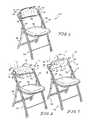
- FIGS. 1–3are perspective views showing a chair including a chair back coupled to left and right chair back mounts included in a frame of the chair for pivotable movement of the chair back about a pivot axis between a home position shown in FIG. 1 and a rearward-leaning pivot position shown in FIG. 2 and a forward-leaning pivot position shown in FIG. 3 ;
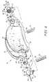
- FIG. 4is an exploded perspective view showing components of the chair back in the middle of the page, components of the left and right chair back mounts on the left and rights sides of the page, and somewhat U-shaped left and right return springs between the chair back and the left and right chair back mounts for returning the chair back to the home position from the rearward-leaning and forward-leaning pivot positions;
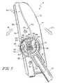
- FIG. 5is a sectional view taken along lines 5 — 5 of FIG. 1 showing the chair back in its home position and showing a tab that is included in the left side of the chair back and positioned between and in engagement with rear (on the left) and front (on the right) spring arms of the left return spring;
- FIG. 6is a sectional view taken along lines 6 — 6 of FIG. 2 showing the chair back pivoted in a rearward direction to its rearward-leaning pivot position and showing engagement between the rear spring arm of the left return spring and a rear pivot limiter to limit pivotable movement of the chair back in the rearward direction;
- FIG. 7is a sectional view taken along lines 7 — 7 of FIG. 3 showing the chair back pivoted in a forward direction to its forward-leaning pivot position and showing engagement between the front spring arm of the left return device and a front pivot limiter to limit pivotable movement of the chair back in the forward direction, and
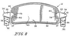
- FIG. 8is a rear elevational view, with portions broken away, showing the chair back mounted on the left and right chair back mounts;
- FIG. 1A chair 10 is shown in FIG. 1 .
- the chair 10includes a chair back 12 mounted to a frame 14 for pivotable movement relative thereto about a pivot axis 16 .
- the chair back 12is pivotable from a home position shown in FIGS. 1 and 5 in a rearward direction 18 to a rearward-leaning pivot position shown in FIGS. 2 and 6 when, for example, a person sitting on the chair 10 leans rearward or backward.
- the chair back 12is also pivotable from the home position in an opposite, forward direction 20 to a forward-leaning pivot position shown in FIGS. 3 and 7 when, for example, a person sitting on the chair 10 leans forward.
- the chair 10includes a chair-back return device 22 , as shown in FIG. 4 .
- the chair-back return device 22is arranged to return the chair back 12 to the home position from the rearward-leaning and forward-leaning pivot positions, as discussed in more detail herein.
- the frame 14includes a front leg unit 24 and a rear leg unit 26 , as shown in FIGS. 1–3 .
- the front and rear leg units 24 , 26are coupled to one another for pivotable movement between an unfolded position (shown in FIGS. 1–3 ) for use of the chair 10 and a folded position (not shown) for storage of the chair 10 .
- a seat 28is mounted to the frame 14 for pivotable movement as the front and rear leg units 24 , 26 are pivoted between the unfolded and folded positions.
- the front leg unit 24includes left and right frame members 30 , 32 and left and right chair back mounts 34 , 36 , as shown in FIGS. 1–4 and 8 .
- the frame members 30 , 32are legs.
- a leg receiver 37 of the left chair back mount 34is mounted to a top portion 38 of the left frame member 30 .
- a leg receiver 37 of the right chair back mount 36is mounted to a top portion 38 of the right frame member 32 .
- the chair back 12is positioned between and mounted to the left and right chair back mounts 34 , 36 for pivotable movement about the pivot axis 16 in the rearward and forward directions 18 , 20 , as shown in FIGS. 1–3 and 8 .
- a left side 40 of the chair back 12is mounted to a left axle 42 of the left chair back mount 34 .
- a right side 44 of the chair back 12is mounted to a right axle 46 of the right chair back mount 36 .
- the left and right axles 42 , 46cooperate to define the pivot axis 16 .
- Front and rear sides 47 , 49 of the chair back 12extend between the left and right sides 40 , 44 .
- Chair back 12 , left axle 42 , and right axle 46cooperate to define a pivotable back unit.
- the chair-back return device 22is arranged to engage at least one of the left and right sides 40 , 44 of the chair back 12 to pivot the chair back 12 to return the chair back 12 to the home position from the rearward-leaning and forward-leaning pivot positions. Stated otherwise, the chair-back return device 22 provides return means for engaging at least one of the left and right sides 40 , 44 of the chair back 12 to pivot the chair back 12 to return the chair back 12 to the home position from the rearward-leaning and forward-leaning pivot positions.
- the chair-back return device 22includes a left return spring 48 and a right return spring 50 , as shown in FIG. 4 .
- the left return spring 48is mounted to a spring mount 52 included in the left chair back mount 34 and is arranged to engage a left motion transmitter 55 included in the left side 40 of the chair back 12 , as shown in FIGS. 5–7 .
- the right return spring 50is mounted to a spring mount 52 included in the right chair back mount 36 and is arranged to engage a right motion transmitter 57 included in the right side 44 .
- Each spring mount 52is mounted to a generally cone-shaped shroud 53 which surrounds the spring mount 52 and the return spring 48 , 50 mounted thereto.
- the motion transmitters 55 , 57are arranged to transmit motion between the return springs 48 , 50 and a back rest 59 included in the chair back 12 , as discussed in more detail herein.
- Each return spring 48 , 50includes a base 54 and relatively movable rear and front flanges or spring arms 56 , 58 , as shown in FIG. 4 with respect to both return springs 48 , 50 and shown in FIGS. 5–7 with respect to return spring 48 .
- the base 54is mounted to an annular base mount 60 included in a spring mount 52 .
- Each base mount 60is formed to include an axle channel 64 through which one of the axles 42 , 46 extends.
- the base 54is C-shaped and fits over the base mount 60 .
- the first and second flanges or spring arms 56 , 58extend radially outwardly from base 54 and are circumferentially spaced from one another.
- Each motion transmitter 55 , 57includes a disk-shaped tab mount 64 and a tab 66 mounted thereto for engagement with a spring 48 , 50 , as shown in FIG. 4 .
- Each tab mount 64is formed to include an axle-receiving opening 68 .
- the left axle 42extends through the axle-receiving opening 68 formed in the tab mount 64 of the left motion transmitter 55 into an axle-receiving opening 70 formed in a front shell member 72 of the back rest 59 .
- the right axle 46extends through the axle-receiving opening 68 formed in the tab mount 64 of the right motion transmitter 57 into an axle-receiving opening 70 formed in the front shell member 72 .
- a pair of transmitter retainers 74 shown in FIG. 4are mounted to an axially inner side of each tab mount 64 .
- the retainers 74extend into corresponding retainer receivers 76 formed in the front shell member 74 so that the motion transmitters 55 , 57 and the back rest 59 pivot with one another.
- An aesthetic portion 78 shown in FIG. 8is mounted to the axially inner side of each tab mount 64 .
- Each aesthetic portion 78extends into a recess 80 formed in a rear shell member 82 included in the back rest 59 .
- the front and rear shell members 72 , 82are coupled to one another by fasteners 84 shown in FIGS. 4–7 to provide the back rest 59 .
- FIGS. 5–7Interaction between the left return spring 48 and the tab 66 of the left motion transmitter 55 is shown in FIGS. 5–7 . The following discussion of such interaction applies also the right return spring 50 and tab 66 of the right motion transmitter 57 .
- the tab 66extends between the rear and front flanges 56 , 58 .
- the tab 66is positioned radially outwardly from a flange or arm stop 86 that is included in the spring mount 52 and extends radially outwardly from the flange mount base 60 .
- the tab 66engages both flanges or spring arms 56 , 58 and both flanges or spring arms 56 , 58 engage the flange or arm stop 86 , as shown in FIG. 5 .
- the tab 66engages the rear flange or spring arm 56 and disengages the front flange or spring arm 58 when the chair back 12 is pivoted in the rearward direction 18 to the rearward-leaning pivot position by a rearward pivot force 88 , as shown in FIG. 6 .
- the tab 66pivots the rear flange or spring arm 56 in the rearward direction 18 away from the front flange or spring arm 58 which remains engaged with the flange or arm stop 86 , thereby rearwardly loading the return spring 48 .
- a rear pivot limiter 87is arranged to limit pivotable movement of the chair back 12 in the rearward direction 18 , as shown in FIG. 6 .
- the rear spring arm 56extends between the rear pivot limiter 87 and the tab 66 so that the rear pivot limiter 87 engages the rear spring arm 56 to limit such rearward pivotable movement.
- the rear pivot limiter 87is a wall mounted to and extending radially inwardly from the shroud 53 .
- the rearwardly loaded return spring 48returns the chair back 12 to the home position when the rearward pivot force 88 is removed from the chair back 12 .
- the rear flange or spring arm 56engages the tab 66 and moves toward the front flange or spring arm 58 to apply a force thereto to pivot the chair back 12 in the forward direction 20 to return the chair back 12 to the home position from the rearward-leaning pivot position.
- the rear flange or spring arm 56re-engages the flange stop 86 upon return of the chair back 12 to the home position.
- the tab 66engages the front flange or spring arm 58 and disengages the rear flange or spring arm 56 when the chair back 12 is pivoted in the forward direction 20 to the forward-leaning pivot position by a forward pivot force 90 , as shown in FIG. 7 .
- the tab 66pivots the front flange or spring arm 58 in the forward direction 20 away from the rear flange or spring arm 56 which remains engaged with the flange or arm stop 86 , thereby forwardly loading the return spring 48 .
- a front pivot limiter 92is arranged to limit pivotable movement of the chair back 12 in the forward direction 20 , as shown in FIG. 7 .
- the front flange or spring arm 58extends between the front pivot limiter 92 and the tab 66 so that the front pivot limiter 92 engages the front flange or spring arm 58 to limit such forward pivotable movement.
- the front pivot limiter 92is a wall mounted to and extending radially inwardly from the shroud 53 .
- the rear and front pivot limiters 87 and 92are spaced circumferentially from one another.
- the forwardly loaded return spring 48returns the chair back 12 to the home position when the forward pivot force 90 is removed from the chair back 12 .
- the front flange or spring arm 58engages the tab 66 and moves toward the rear flange or spring arm 56 to apply a force thereto to pivot the chair back 12 in the rearward direction 18 to return the chair back 12 to the home position from the forwardly-leaning pivot position.
- the front flange or spring arm 58re-engages the flange stop 86 upon return of the chair back 12 to the home position.
- a set of rear and front pivot limiters 87 , 92are also mounted to the shroud 53 of the right chair back mount 36 , as shown in FIG. 4 . They operate in the same manner with respect to the right return spring 50 as described in connection with the rear and front pivot limiters 87 , 92 associated with the left return spring 48 .
- the rear pivot limiters 87 and the front pivot limiters 92cooperate to define a pivot limiter device arranged to limit pivotable movement of the chair back 12 away from the home position in the rearward and forward directions 18 , 20 .
- the pivot limiter devicethus provides means for limiting pivotable movement of the chair back 12 away from the home position in the rearward and forward directions 18 , 20 .
Landscapes
- Chairs Characterized By Structure (AREA)
Abstract
Description
Claims (15)
Priority Applications (1)
| Application Number | Priority Date | Filing Date | Title |
|---|---|---|---|
| US10/640,229US6974188B2 (en) | 2003-08-13 | 2003-08-13 | Chair with pivotable chair back |
Applications Claiming Priority (1)
| Application Number | Priority Date | Filing Date | Title |
|---|---|---|---|
| US10/640,229US6974188B2 (en) | 2003-08-13 | 2003-08-13 | Chair with pivotable chair back |
Publications (2)
| Publication Number | Publication Date |
|---|---|
| US20050035636A1 US20050035636A1 (en) | 2005-02-17 |
| US6974188B2true US6974188B2 (en) | 2005-12-13 |
Family
ID=34136056
Family Applications (1)
| Application Number | Title | Priority Date | Filing Date |
|---|---|---|---|
| US10/640,229Expired - Fee RelatedUS6974188B2 (en) | 2003-08-13 | 2003-08-13 | Chair with pivotable chair back |
Country Status (1)
| Country | Link |
|---|---|
| US (1) | US6974188B2 (en) |
Cited By (13)
| Publication number | Priority date | Publication date | Assignee | Title |
|---|---|---|---|---|
| USD533000S1 (en)* | 2005-02-18 | 2006-12-05 | Atico International Usa, Inc. | Connector housing of an anti-pinching device of a folding chair |
| US20110221253A1 (en)* | 2006-03-24 | 2011-09-15 | Manuel Saez | Ergonomic Side Chair |
| US20110227387A1 (en)* | 2010-03-16 | 2011-09-22 | Michael Kolich | Occupant controlled multi-surface head restraint for improved comfort |
| US20120319444A1 (en)* | 2011-06-14 | 2012-12-20 | Paul Onopa | Sitting and Standing Chair |
| US8348346B2 (en) | 2010-04-22 | 2013-01-08 | Ford Global Technologies, Llc | Recliner with dual functions |
| US20160374471A1 (en)* | 2015-06-23 | 2016-12-29 | Dennis Colonello | Rotatable seat cradle |
| US20170340120A1 (en)* | 2016-05-27 | 2017-11-30 | Su-Ming Chen | Structure for chair backrest |
| US10099591B2 (en)* | 2016-12-01 | 2018-10-16 | David Flynn | Dual configuration headrest system |
| USD839650S1 (en)* | 2017-04-26 | 2019-02-05 | Lifetime Products, Inc. | Chair |
| US10806264B1 (en)* | 2019-10-09 | 2020-10-20 | Inno-Sports Co., Ltd. | Chair having adjustable backrest |
| USD982340S1 (en) | 2019-09-20 | 2023-04-04 | Inno-Sports Co., Ltd. | Chair |
| US20230371713A1 (en)* | 2022-05-18 | 2023-11-23 | The Ergo Baby Carrier, Inc. | Convertible platform for supporting a user |
| US20240342025A1 (en)* | 2022-02-28 | 2024-10-17 | Board Of Trustees Of Michigan State University | Articulating Chair |
Families Citing this family (10)
| Publication number | Priority date | Publication date | Assignee | Title |
|---|---|---|---|---|
| US20060074608A1 (en)* | 2004-10-01 | 2006-04-06 | Freeman Clay | System and method for designing building structures with associated estimates and schedules |
| FR2916331A1 (en)* | 2007-05-25 | 2008-11-28 | Inova Creations Sa | Backrest fixing device for use with seat, has backrest fixed to posts by two symmetrically identical and articulated fixation pieces i.e. attachments, where each piece corresponds to one of posts of seat |
| EP2434929B1 (en)* | 2009-05-27 | 2014-12-10 | Steelcase Sa | Method for tilting the backrest of a seat |
| DE102010047285A1 (en)* | 2010-09-23 | 2012-03-29 | Viasit Bürositzmöbel Gmbh | Chair, in particular work chair |
| JP2018538119A (en)* | 2015-11-23 | 2018-12-27 | アンドリュ,ラファエル ブラスコ | Improved self-adjustable backrest device |
| CN107095504A (en)* | 2016-07-22 | 2017-08-29 | 孟祥厚 | With the docile and obedient chair of the back of the body |
| USD801062S1 (en)* | 2016-07-27 | 2017-10-31 | Yu-Shan Lin | Folding chair |
| ES1288684Y (en) | 2021-11-18 | 2022-06-22 | Andreu Rafael Blasco | TILT DEVICE FOR BACKREST |
| USD1056538S1 (en)* | 2022-11-03 | 2025-01-07 | New-Tec Integration (Xiamen) Co., Ltd. | Iron chair |
| CN116211089A (en)* | 2023-03-10 | 2023-06-06 | 吉同武 | A waist support chair with dynamic following function |
Citations (54)
| Publication number | Priority date | Publication date | Assignee | Title |
|---|---|---|---|---|
| US349907A (en)* | 1886-09-28 | Chair | ||
| US1150189A (en)* | 1914-10-03 | 1915-08-17 | Barney And Smith Car Company | Chair. |
| US1263161A (en) | 1917-10-11 | 1918-04-16 | Gilson Mfg Co | Adjustment for the backs of type-writer chairs. |
| US1910760A (en) | 1928-10-15 | 1933-05-23 | Fritz Cross Company | Chair |
| US2524624A (en) | 1946-08-14 | 1950-10-03 | Roy A Cramer | Resilient chair back mounting |
| US2662588A (en) | 1952-09-08 | 1953-12-15 | William A Clark | Cushion spring structure |
| US2692012A (en) | 1946-03-29 | 1954-10-19 | Cramer Posture Chair Co Inc | Adjustable chair back pivoted above seat |
| US2703601A (en) | 1951-07-17 | 1955-03-08 | Domore Chair Company Inc | Back rest supporting structure for chairs |
| US2801678A (en)* | 1953-07-02 | 1957-08-06 | Coach & Car Equipment Corp | Adjustable head rest for seat structure |
| US3186763A (en)* | 1962-07-26 | 1965-06-01 | Gen Motors Corp | Headrest |
| US3215468A (en)* | 1965-03-01 | 1965-11-02 | Milsco Mfg Co | Seat for material handling vehicles |
| US3351378A (en) | 1965-11-09 | 1967-11-07 | Blisscraft Of Hollywood | Chair |
| US3365233A (en) | 1966-06-20 | 1968-01-23 | Samsonite Corp | Stacking chairs |
| US3402963A (en) | 1967-05-22 | 1968-09-24 | Samsonite Corp | Chair tiering attachments |
| US3603640A (en) | 1969-09-23 | 1971-09-07 | Doerner Procucts Co Ltd | Chair control with torsion spring with tilting seat and chair back |
| US3610686A (en) | 1969-10-10 | 1971-10-05 | Shelby Williams Ind | Cast-aluminum stack chair |
| US3637256A (en) | 1969-06-16 | 1972-01-25 | Shaw Walker Co | Chair construction |
| US3695684A (en) | 1970-07-02 | 1972-10-03 | Vernon G Barberg | Multi-use, body-relaxing furniture unit |
| US3697130A (en) | 1971-04-20 | 1972-10-10 | American Seating Co | Connector assembly for chairs |
| US3758155A (en) | 1972-03-16 | 1973-09-11 | Interlake Inc | Gang chair construction |
| US3826453A (en) | 1973-02-21 | 1974-07-30 | Shaw Walker Co | Ganging chairs |
| US3847433A (en) | 1973-07-12 | 1974-11-12 | American Seating Co | Stacking chair |
| US3989297A (en) | 1973-01-29 | 1976-11-02 | Fritz Kerstholt | Chair or couch with a movable back support |
| US4135836A (en) | 1977-11-30 | 1979-01-23 | Steelcase Inc. | Chair back with polymer spring |
| US4157203A (en) | 1977-05-09 | 1979-06-05 | Center For Design Research And Development N.V. | Articulated double back for chairs |
| US4316632A (en) | 1978-09-08 | 1982-02-23 | Protoned Bv | Ergonomic chair |
| US4386804A (en) | 1981-04-06 | 1983-06-07 | Krueger Metal Products, Inc. | Chair ganging equipment |
| US4400032A (en) | 1978-04-05 | 1983-08-23 | Depolo Harry R | Eccentrically rotatable chair |
| US4400031A (en) | 1981-03-12 | 1983-08-23 | Virco Mfg. Corporation | Interlocking chair |
| US4597604A (en) | 1983-12-30 | 1986-07-01 | Mark Singer | Support structures for chairs and the like having pivoting members |
| US4600240A (en)* | 1984-03-09 | 1986-07-15 | Prince Corporation | Headrest control |
| US4978171A (en)* | 1989-02-27 | 1990-12-18 | Ikeda Bussan Co., Ltd. | Arm rest device for use with vehicular seat |
| US5308143A (en)* | 1992-09-23 | 1994-05-03 | Joanna A. Nichols | Safety rocker for an infant seat |
| US5531505A (en)* | 1994-02-25 | 1996-07-02 | Tri-Con Industries, Ltd. | Head restraint for passenger vehicles |
| US5597209A (en)* | 1995-05-11 | 1997-01-28 | Hoover Universal, Inc. | Adjustable vehicle seat armrest with a ratchet |
| US5669668A (en)* | 1995-08-03 | 1997-09-23 | General Motors Corporation | Folding headrest in particular for motor vehicles |
| US5683142A (en) | 1996-06-20 | 1997-11-04 | Krueger International, Inc. | Mounting assembly for chair back |
| US5803546A (en)* | 1996-08-02 | 1998-09-08 | Kabushiki Kaisha Kotobuki | Turning mechanism for chair seat |
| US5882069A (en)* | 1998-02-17 | 1999-03-16 | The Board Of Trustees Of Western Michigan University | Multi-functional bench seat |
| US5906414A (en)* | 1997-10-09 | 1999-05-25 | Lear Corporation | Snap-on, pivotable vehicle headrest assembly |
| USRE36335E (en)* | 1988-04-25 | 1999-10-12 | Perry; Charles O. | Flexible chair |
| US6050645A (en)* | 1998-03-04 | 2000-04-18 | Tachi-S Engineering U.S.A., Inc. | Clutching mechanism for an infinitely adjustable armrest |
| US6079776A (en)* | 1997-09-06 | 2000-06-27 | Daimlerchrysler Ag | Headrest for a vehicle seat |
| US6095611A (en) | 1997-10-07 | 2000-08-01 | Roho, Inc. | Modular backrest system for a wheelchair |
| US6250716B1 (en)* | 2000-09-20 | 2001-06-26 | Robert Clough | Seat headrest |
| US6257665B1 (en) | 1998-07-09 | 2001-07-10 | Okamura Corporation | Chair |
| US6257668B1 (en)* | 1999-08-09 | 2001-07-10 | Ding-Guo Chou | Chair armrest joint adjustable for 360° in any direction about a shaft |
| US6305747B1 (en) | 2000-06-05 | 2001-10-23 | Teng-Fu Mei | Swayable backrest assembly for a chair |
| US6478379B1 (en)* | 2000-06-07 | 2002-11-12 | Center For Design Research And Development N.V. | Chair |
| US6481789B1 (en)* | 1999-06-18 | 2002-11-19 | Center For Design Research And Development N.V. | Stackable chair |
| US6482798B2 (en)* | 1996-07-25 | 2002-11-19 | Bayer Aktiengesellschaft | Aprotinin variants having improved properties |
| US6530622B1 (en)* | 2001-03-16 | 2003-03-11 | Johnson Controls Technology Company | Biomechanical vehicle seat |
| US6612653B2 (en)* | 2001-01-04 | 2003-09-02 | Delta Tooling Co., Ltd. | Retractable headrest for seat assembly |
| US6655731B2 (en)* | 2001-09-26 | 2003-12-02 | Charles N. Martin | Therapeutic chair |
- 2003
- 2003-08-13USUS10/640,229patent/US6974188B2/ennot_activeExpired - Fee Related
Patent Citations (54)
| Publication number | Priority date | Publication date | Assignee | Title |
|---|---|---|---|---|
| US349907A (en)* | 1886-09-28 | Chair | ||
| US1150189A (en)* | 1914-10-03 | 1915-08-17 | Barney And Smith Car Company | Chair. |
| US1263161A (en) | 1917-10-11 | 1918-04-16 | Gilson Mfg Co | Adjustment for the backs of type-writer chairs. |
| US1910760A (en) | 1928-10-15 | 1933-05-23 | Fritz Cross Company | Chair |
| US2692012A (en) | 1946-03-29 | 1954-10-19 | Cramer Posture Chair Co Inc | Adjustable chair back pivoted above seat |
| US2524624A (en) | 1946-08-14 | 1950-10-03 | Roy A Cramer | Resilient chair back mounting |
| US2703601A (en) | 1951-07-17 | 1955-03-08 | Domore Chair Company Inc | Back rest supporting structure for chairs |
| US2662588A (en) | 1952-09-08 | 1953-12-15 | William A Clark | Cushion spring structure |
| US2801678A (en)* | 1953-07-02 | 1957-08-06 | Coach & Car Equipment Corp | Adjustable head rest for seat structure |
| US3186763A (en)* | 1962-07-26 | 1965-06-01 | Gen Motors Corp | Headrest |
| US3215468A (en)* | 1965-03-01 | 1965-11-02 | Milsco Mfg Co | Seat for material handling vehicles |
| US3351378A (en) | 1965-11-09 | 1967-11-07 | Blisscraft Of Hollywood | Chair |
| US3365233A (en) | 1966-06-20 | 1968-01-23 | Samsonite Corp | Stacking chairs |
| US3402963A (en) | 1967-05-22 | 1968-09-24 | Samsonite Corp | Chair tiering attachments |
| US3637256A (en) | 1969-06-16 | 1972-01-25 | Shaw Walker Co | Chair construction |
| US3603640A (en) | 1969-09-23 | 1971-09-07 | Doerner Procucts Co Ltd | Chair control with torsion spring with tilting seat and chair back |
| US3610686A (en) | 1969-10-10 | 1971-10-05 | Shelby Williams Ind | Cast-aluminum stack chair |
| US3695684A (en) | 1970-07-02 | 1972-10-03 | Vernon G Barberg | Multi-use, body-relaxing furniture unit |
| US3697130A (en) | 1971-04-20 | 1972-10-10 | American Seating Co | Connector assembly for chairs |
| US3758155A (en) | 1972-03-16 | 1973-09-11 | Interlake Inc | Gang chair construction |
| US3989297A (en) | 1973-01-29 | 1976-11-02 | Fritz Kerstholt | Chair or couch with a movable back support |
| US3826453A (en) | 1973-02-21 | 1974-07-30 | Shaw Walker Co | Ganging chairs |
| US3847433A (en) | 1973-07-12 | 1974-11-12 | American Seating Co | Stacking chair |
| US4157203A (en) | 1977-05-09 | 1979-06-05 | Center For Design Research And Development N.V. | Articulated double back for chairs |
| US4135836A (en) | 1977-11-30 | 1979-01-23 | Steelcase Inc. | Chair back with polymer spring |
| US4400032A (en) | 1978-04-05 | 1983-08-23 | Depolo Harry R | Eccentrically rotatable chair |
| US4316632A (en) | 1978-09-08 | 1982-02-23 | Protoned Bv | Ergonomic chair |
| US4400031A (en) | 1981-03-12 | 1983-08-23 | Virco Mfg. Corporation | Interlocking chair |
| US4386804A (en) | 1981-04-06 | 1983-06-07 | Krueger Metal Products, Inc. | Chair ganging equipment |
| US4597604A (en) | 1983-12-30 | 1986-07-01 | Mark Singer | Support structures for chairs and the like having pivoting members |
| US4600240A (en)* | 1984-03-09 | 1986-07-15 | Prince Corporation | Headrest control |
| USRE36335E (en)* | 1988-04-25 | 1999-10-12 | Perry; Charles O. | Flexible chair |
| US4978171A (en)* | 1989-02-27 | 1990-12-18 | Ikeda Bussan Co., Ltd. | Arm rest device for use with vehicular seat |
| US5308143A (en)* | 1992-09-23 | 1994-05-03 | Joanna A. Nichols | Safety rocker for an infant seat |
| US5531505A (en)* | 1994-02-25 | 1996-07-02 | Tri-Con Industries, Ltd. | Head restraint for passenger vehicles |
| US5597209A (en)* | 1995-05-11 | 1997-01-28 | Hoover Universal, Inc. | Adjustable vehicle seat armrest with a ratchet |
| US5669668A (en)* | 1995-08-03 | 1997-09-23 | General Motors Corporation | Folding headrest in particular for motor vehicles |
| US5683142A (en) | 1996-06-20 | 1997-11-04 | Krueger International, Inc. | Mounting assembly for chair back |
| US6482798B2 (en)* | 1996-07-25 | 2002-11-19 | Bayer Aktiengesellschaft | Aprotinin variants having improved properties |
| US5803546A (en)* | 1996-08-02 | 1998-09-08 | Kabushiki Kaisha Kotobuki | Turning mechanism for chair seat |
| US6079776A (en)* | 1997-09-06 | 2000-06-27 | Daimlerchrysler Ag | Headrest for a vehicle seat |
| US6095611A (en) | 1997-10-07 | 2000-08-01 | Roho, Inc. | Modular backrest system for a wheelchair |
| US5906414A (en)* | 1997-10-09 | 1999-05-25 | Lear Corporation | Snap-on, pivotable vehicle headrest assembly |
| US5882069A (en)* | 1998-02-17 | 1999-03-16 | The Board Of Trustees Of Western Michigan University | Multi-functional bench seat |
| US6050645A (en)* | 1998-03-04 | 2000-04-18 | Tachi-S Engineering U.S.A., Inc. | Clutching mechanism for an infinitely adjustable armrest |
| US6257665B1 (en) | 1998-07-09 | 2001-07-10 | Okamura Corporation | Chair |
| US6481789B1 (en)* | 1999-06-18 | 2002-11-19 | Center For Design Research And Development N.V. | Stackable chair |
| US6257668B1 (en)* | 1999-08-09 | 2001-07-10 | Ding-Guo Chou | Chair armrest joint adjustable for 360° in any direction about a shaft |
| US6305747B1 (en) | 2000-06-05 | 2001-10-23 | Teng-Fu Mei | Swayable backrest assembly for a chair |
| US6478379B1 (en)* | 2000-06-07 | 2002-11-12 | Center For Design Research And Development N.V. | Chair |
| US6250716B1 (en)* | 2000-09-20 | 2001-06-26 | Robert Clough | Seat headrest |
| US6612653B2 (en)* | 2001-01-04 | 2003-09-02 | Delta Tooling Co., Ltd. | Retractable headrest for seat assembly |
| US6530622B1 (en)* | 2001-03-16 | 2003-03-11 | Johnson Controls Technology Company | Biomechanical vehicle seat |
| US6655731B2 (en)* | 2001-09-26 | 2003-12-02 | Charles N. Martin | Therapeutic chair |
Non-Patent Citations (2)
| Title |
|---|
| Artland(R) product information (5 pages) (before Aug. 2003). |
| Gauss Seating Corporation product information (4 pages) (before Aug. 2003). |
Cited By (16)
| Publication number | Priority date | Publication date | Assignee | Title |
|---|---|---|---|---|
| USD533000S1 (en)* | 2005-02-18 | 2006-12-05 | Atico International Usa, Inc. | Connector housing of an anti-pinching device of a folding chair |
| US20110221253A1 (en)* | 2006-03-24 | 2011-09-15 | Manuel Saez | Ergonomic Side Chair |
| US20110227387A1 (en)* | 2010-03-16 | 2011-09-22 | Michael Kolich | Occupant controlled multi-surface head restraint for improved comfort |
| US8348346B2 (en) | 2010-04-22 | 2013-01-08 | Ford Global Technologies, Llc | Recliner with dual functions |
| US20120319444A1 (en)* | 2011-06-14 | 2012-12-20 | Paul Onopa | Sitting and Standing Chair |
| US11089874B2 (en) | 2015-06-23 | 2021-08-17 | Simtec, Inc. | Rotatable seat cradle |
| US20160374471A1 (en)* | 2015-06-23 | 2016-12-29 | Dennis Colonello | Rotatable seat cradle |
| US10314400B2 (en)* | 2015-06-23 | 2019-06-11 | Simtec, Llc | Rotatable seat cradle |
| US20170340120A1 (en)* | 2016-05-27 | 2017-11-30 | Su-Ming Chen | Structure for chair backrest |
| US10099591B2 (en)* | 2016-12-01 | 2018-10-16 | David Flynn | Dual configuration headrest system |
| USD839650S1 (en)* | 2017-04-26 | 2019-02-05 | Lifetime Products, Inc. | Chair |
| USD982340S1 (en) | 2019-09-20 | 2023-04-04 | Inno-Sports Co., Ltd. | Chair |
| US10806264B1 (en)* | 2019-10-09 | 2020-10-20 | Inno-Sports Co., Ltd. | Chair having adjustable backrest |
| US20240342025A1 (en)* | 2022-02-28 | 2024-10-17 | Board Of Trustees Of Michigan State University | Articulating Chair |
| US12161592B2 (en)* | 2022-02-28 | 2024-12-10 | Board Of Trustees Of Michigan State University | Articulating chair |
| US20230371713A1 (en)* | 2022-05-18 | 2023-11-23 | The Ergo Baby Carrier, Inc. | Convertible platform for supporting a user |
Also Published As
| Publication number | Publication date |
|---|---|
| US20050035636A1 (en) | 2005-02-17 |
Similar Documents
| Publication | Publication Date | Title |
|---|---|---|
| US6974188B2 (en) | Chair with pivotable chair back | |
| AU672940B2 (en) | Swivel recliner/rocker chair having preloaded base assembly | |
| CN105455480B (en) | Headrest tilting mechanism | |
| US4968095A (en) | Seat back arm recliner | |
| EP2429344B1 (en) | Improved recliner ottoman linkage with unique secondary ottoman | |
| US5294177A (en) | Automatic block for rocker chairs | |
| EP1060695B1 (en) | Stackable chair | |
| JPH0236245B2 (en) | ||
| US20090218872A1 (en) | Vehicular seats | |
| KR101928964B1 (en) | Folding type chair with sliding seat | |
| US11197548B2 (en) | Reclining control system for a chair | |
| CA2510906A1 (en) | Collapsible reclining chair | |
| WO2004107917A8 (en) | Chair having automatically adjustable backrest | |
| US20110210593A1 (en) | Chair with collapsible seat back | |
| US20200383478A1 (en) | Tilting chair | |
| EP1618816B1 (en) | Portable backrest structure | |
| US2912045A (en) | Adjustable backrest mechanism | |
| JP6172988B2 (en) | Chair | |
| US20210244187A1 (en) | Seat Chassis | |
| JPH0956522A (en) | Automatic standing device for a seat in a jump chair | |
| KR20170075223A (en) | Chair with back tilting angle adjustment and automatic tilting return function | |
| CN218683114U (en) | Seat plate and back linkage seat | |
| CN210902228U (en) | Chair with tiltable backrest | |
| US3542422A (en) | Unison action recliner | |
| WO2025089967A1 (en) | A piece of sitting furniture comprising a backrest, a seat, and a functional unit, the functional unit being designed and equipped to be attached to a base, and a use of the piece of sitting furniture |
Legal Events
| Date | Code | Title | Description |
|---|---|---|---|
| AS | Assignment | Owner name:COSCO MANAGEMENT, INC., DELAWARE Free format text:ASSIGNMENT OF ASSIGNORS INTEREST;ASSIGNORS:TURNER, DENNIS M.;ZINK, PAUL T.;ANDREWS, JASON;REEL/FRAME:014521/0399 Effective date:20030812 | |
| FPAY | Fee payment | Year of fee payment:4 | |
| FPAY | Fee payment | Year of fee payment:8 | |
| AS | Assignment | Owner name:AMERIWOOD INDUSTRIES, INC., MISSOURI Free format text:ASSIGNMENT OF ASSIGNORS INTEREST;ASSIGNOR:COSCO MANAGEMENT, INC.;REEL/FRAME:034485/0130 Effective date:20141125 | |
| AS | Assignment | Owner name:DOREL HOME FURNISHINGS, INC., MISSOURI Free format text:CHANGE OF NAME;ASSIGNOR:AMERIWOOD INDUSTRIES, INC.;REEL/FRAME:040147/0673 Effective date:20160912 | |
| REMI | Maintenance fee reminder mailed | ||
| LAPS | Lapse for failure to pay maintenance fees | Free format text:PATENT EXPIRED FOR FAILURE TO PAY MAINTENANCE FEES (ORIGINAL EVENT CODE: EXP.) | |
| STCH | Information on status: patent discontinuation | Free format text:PATENT EXPIRED DUE TO NONPAYMENT OF MAINTENANCE FEES UNDER 37 CFR 1.362 | |
| FP | Lapsed due to failure to pay maintenance fee | Effective date:20171213 |