US6973287B2 - Apparatus and method to implement a flexible hub-spoke satellite communications network - Google Patents
Apparatus and method to implement a flexible hub-spoke satellite communications networkDownload PDFInfo
- Publication number
- US6973287B2 US6973287B2US10/044,131US4413102AUS6973287B2US 6973287 B2US6973287 B2US 6973287B2US 4413102 AUS4413102 AUS 4413102AUS 6973287 B2US6973287 B2US 6973287B2
- Authority
- US
- United States
- Prior art keywords
- spot beams
- satellite
- spot
- beams
- antenna
- Prior art date
- Legal status (The legal status is an assumption and is not a legal conclusion. Google has not performed a legal analysis and makes no representation as to the accuracy of the status listed.)
- Expired - Lifetime, expires
Links
- 238000000034methodMethods0.000titleclaimsdescription13
- 238000004891communicationMethods0.000titledescription19
- 238000012360testing methodMethods0.000claimsdescription53
- 238000001914filtrationMethods0.000claimsdescription4
- 238000010998test methodMethods0.000claims1
- 210000004027cellAnatomy0.000description31
- 238000010586diagramMethods0.000description7
- 238000013459approachMethods0.000description3
- 230000005540biological transmissionEffects0.000description3
- 238000013461designMethods0.000description3
- 210000003719b-lymphocyteAnatomy0.000description2
- 230000008901benefitEffects0.000description2
- 230000008859changeEffects0.000description2
- 230000001419dependent effectEffects0.000description2
- 238000012986modificationMethods0.000description2
- 230000004048modificationEffects0.000description2
- 230000000712assemblyEffects0.000description1
- 238000000429assemblyMethods0.000description1
- 238000007796conventional methodMethods0.000description1
- 238000013507mappingMethods0.000description1
- 239000011159matrix materialSubstances0.000description1
- 230000007246mechanismEffects0.000description1
- 230000010355oscillationEffects0.000description1
- 230000010287polarizationEffects0.000description1
- 230000008569processEffects0.000description1
- 238000012545processingMethods0.000description1
- 238000001228spectrumMethods0.000description1
Images


Classifications
- H—ELECTRICITY
- H04—ELECTRIC COMMUNICATION TECHNIQUE
- H04B—TRANSMISSION
- H04B7/00—Radio transmission systems, i.e. using radiation field
- H04B7/14—Relay systems
- H04B7/15—Active relay systems
- H04B7/185—Space-based or airborne stations; Stations for satellite systems
- H04B7/1851—Systems using a satellite or space-based relay
- H04B7/18519—Operations control, administration or maintenance
- H—ELECTRICITY
- H04—ELECTRIC COMMUNICATION TECHNIQUE
- H04B—TRANSMISSION
- H04B7/00—Radio transmission systems, i.e. using radiation field
- H04B7/14—Relay systems
- H04B7/15—Active relay systems
- H04B7/204—Multiple access
- H04B7/2041—Spot beam multiple access
Definitions
- This inventionrelates generally to the field of communications.
- the inventionrelates to apparatus and methods to implement a flexible hub-spoke satellite communications network.
- FIG. 1is an illustration of a conventional satellite communications network in which two satellites provide redundancy for communications. Satellites 620 and 640 communicate with ground stations 630 located within a region of Earth 610 using a uniform coverage distribution methodology. This uniform coverage distribution methodology would allow for communications to an entire region of Earth 610 , such as, but not limited to, North America. If one of satellite 620 or satellite 640 should ever fail, then the other satellite takes over its communications function.
- FIG. 2is an example illustration of spot beams positioned over predefined Earth locations in a non-uniform coverage distribution utilizing the previously mentioned hemispherical earth coverage.
- a satellite 710is shown located at 47 degrees west longitude. Satellite 710 positions its spot beams 740 to cover South America and the east coast of the United States. Further, the positioning of the spot beams is dependent upon the physical alignment of the feeds in the antenna of the satellite and the longitude at which the satellite is positioned in geo-synchronous orbit as detailed in U.S. Pat. Nos. 6,211,835; 6,215,452; and 6,236,375 incorporated herein by reference in their entireties. Once the feeds are set within a satellite they may not be changed individually to target another geographical location. However, unlike a uniform coverage distribution methodology, the spot beams may be directed towards those areas where demand is highest and profitability maximized. Therefore, the positioning of feeds to generate spot beams is critical in determining the profitability of a satellite communications network.
- Spot beam broadband systemsfrequently divide the system's capacity into beam groups.
- each groupconsists of a number of coverage regions on the ground and the related satellite resources allocated to serving these regions.
- the gatewayFor hub-spoke networks, there is an uplink generated from one site, the gateway.
- Conventional hub-spoke systemsgenerally require the gateway to be within a pre-determined coverage area.
- the payload on the satellitecan have switches to change the location from which a spot beam is transmitted or received, and individual examples of switching are common.
- IOTin-orbit test
- G/TReceive Gain to System Temperature ratio
- EIRPEffective Isotropic Radiated Power
- bandwidthbandwidth
- C/Iuplink and downlink carrier to interference
- a conventional method for testing a satelliteis by transmitting a beam or signal up to the satellite and having the satellite relay that signal back down to a ground station or test station located on Earth. Parameters of the received signal may then be compared against parameters of the signal that was originally transmitted up to the satellite.
- Traditional satellitesmay only have a few beams and testing can be performed from one or a small number of ground station locations.
- logistical problemsmay occur during the testing phase. In such a circumstance, it may be expensive and extremely difficult and laborious to test each uplink beam and each downlink beam.
- each beammay transmit a signal up to the satellite and have the signal relayed back down to Earth in a second beam.
- Thismay entail an exceptionally large number of ground stations or test stations to be positioned at different locations around Earth corresponding to each beam under test.
- This type of testingis extremely laborious as it may involve a large number of ground stations for transmitting or receiving the beams.
- On-board test signal generatorsare also known, but this solution is also expensive. It is therefore desirable to provide a means for more efficiently testing multi-beam satellites.
- the preferred embodimentsinvolve a satellite communications network having the maximum feasible bandwidth and on-orbit capacity reallocation capability. This general objective is provided by a practical and simple implementation of the on-orbit flexibility enabled by modern antenna designs which is low cost, low mass and low power.
- An objective of the preferred embodimentsis to provide a hub-spoke communications network based on a multi-beam satellite that can on-orbit, for an uplink beam, pull off signal information, in real-time from each spot beam within a chosen group and input the signal information into a flexible uplink implementation.
- the flexible uplink implementationselects a combination of spot beams and processes the desired uplink capacity for each beam.
- Such a networkprovides maximum bandwidth and on-orbit reallocation of channel capability between spot beams in any chosen beam group.
- the preferred embodimentsalso seek to eliminate the cost and mass of an on-orbit test unit, or the expense of multiple test sites.
- the preferred embodimentsprovide the ability to test from a single site via connectivity switching.
- the flexible uplink implementationallows on-orbit reassignment of uplink bandwidth among a group of user cells.
- the signal from a given spot beamis power divided and routed to a set of switches and a multiplexer.
- the switches and multiplexermay select the signal, filter the signal, and combine it with other signals.
- the combined signalwill then be amplified, and transmitted via a downlink beam.
- the switches and multiplexerprovide an inexpensive, on-orbit method to enable a spot beam by spot beam checkout and test.
- the flexible uplinkallows connectivity, for test purposes only, of the uplink from each cell to the downlink to the same cell. In other words, it allows each cell to act as a gateway in terms of uplink signal connectivity. This allows testing of all spot beams from a single test site—the site generates an uplink and observes the downlink. Performance within each beam is tested by re-pointing the satellite antennas in a scan pattern. Each beam can be tested this way in turn by repositioning the beams and commanding the appropriate uplink connectivity.
- This configurationallows the test signal from one earth station to be used to test each satellite spot beam one by one. This allows each user beam to look like the gateway for the purposes of test.
- FIG. 1is an illustration of a conventional satellite communication network having two satellites providing total redundancy
- FIG. 2is an example illustration of spot beams positioned over predefined Earth locations utilizing a hemispherical earth coverage antenna
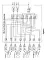
- FIG. 3is a block diagram of the payload circuitry in the example embodiments of the invention.
- FIG. 4is a diagram illustrating the flexibility of capacity in a satellite in order to re-allocate capacity within a geographical area where demand has unexpectedly changed;
- FIG. 5is a diagram of the beam group flexibility in the example embodiments of the present invention.
- FIG. 6is a detailed block diagram of a first example of the Uplink 4:2 Connectivity Switching 210 in the payload architecture shown in FIG. 3 .
- FIG. 7is a detailed block diagram of a second example of the Uplink 4:2 Connectivity Switching 210 in the payload architecture shown in FIG. 3 .
- the preferred embodiments of the present inventionwill now be described with respect to a multi-beam satellite that includes an input section set to receive a plurality of beams in a beam group (from Earth) and an output section set to transmit a plurality of beams in a beam group (to Earth).
- a payload architectureis coupled between the input section and the output section.
- the payload architectureincludes a flexible implementation to provide a combination of switching and filtering signals corresponding to the first plurality of beams (i.e., uplink beams) received at the input section and routed to the output section to be transmitted as the second plurality of beams (i.e., downlink beams)to give specific desired operational benefits.
- the preferred embodimentsare merely exemplary, and are in no way intended to limit the invention or its applications or uses.
- the terminologies of signal, signals, beam or beamsmay be used throughout and are meant to be interchangeable.
- the exemplary satellite payload architectureis capable of receiving high frequency uplink beams at a plurality of receive antennas, converting the higher frequency to a lower frequency for switching of channels, converting the lower frequency signals to a higher frequency, and distributing the high power signals to one of the plurality of transmit antennas.
- FIG. 3is a block diagram illustrating electronics in a payload for one beam group of a multi-beam satellite according to the preferred embodiments of the present invention.
- the satellite payloadmay include similar electronics for each of the other beam groups.
- the satellitemay include various types of antenna structures for receiving and transmitting numerous beam groups, for example, eight beam groups. For example, there may be a first antenna or antenna set to receive uplink spot beams and a second antenna or antenna set to receive downlink spot beams. Alternatively, there may be one or more shared antenna apertures, each receiving and transmitting uplink and downlink spot beams.
- FIG. 3shows a first dual-polarization antenna 20 , a second dual-polarization antenna 30 , a third dual-polarization antenna 40 and a fourth dual-polarization antenna 50 each to receive uplink beams from Earth in a well-known manner.
- the uplink signalssuch as broadband communication signals
- the received signalspass through four ortho-mode transducers (OMT) 110 to eight band pass filters (BPF) 120 .
- the filtered signalsmay pass to eight low noise amplifier down-converters (LNA D/C) 130 that convert the received and filtered signals from a higher frequency (such as approximately 30 GHz in the Ka-band) to a lower frequency (such as approximately 4 or 5 GHz in the C-Band).
- LNA D/Clow noise amplifier down-converters
- the lower frequency C-Band signalsmay then be amplified by eight C-Band utility amplifiers 140 and proceed to an Input Multiplexer (IMUX) and switching assembly 200 .
- the IMUX and switching assembly 200may include an uplink 4:2 connectivity switching network 210 , which may be a power dividing switching network. Signals output from the uplink 4:2 connectivity switching network 210 may be input to either one of the two outbound input multiplexers (IMUX) 220 or to the 4:1 inverse IMUX 230 .
- the IMUXs' 220 outputs O 1 , O 2 , O 3 , and O 4are connected to a C-Band redundancy switching network 310 .
- the 4:1 inverse IMUX 230 output I 1is connected to the C-Band redundancy switching network 310 .
- the C-Band redundancy switching network 310 outputsare connected to five up-converters (U/C) 320 .
- the U/Cs 320convert the lower frequency signals to higher K-band frequency signals (such as approximately 20 GHz) that will be used for transmission back to the Earth.
- the higher frequency K-band signalsmay then pass through five K-band linearized channel amplifiers 330 and five TWTAs 340 .
- the five TWTAs 340are high power amplifiers that supply the transmit RF power to achieve the downlink transmission.
- the five TWTAs 340output four high power outbound signals O- 1 , O- 2 , O- 3 , O- 4 to the users and one inbound signal I- 1 to the gateway (not shown).
- the K-band redundancy switching network 350connects the outbound signals O- 1 , O- 2 , O- 3 and O- 4 to an Output Multiplexer (OMUX) and switching assembly 400 .
- OFUXOutput Multiplexer
- the OMUX and switching assembly 400may include mechanical switches 410 that couple the outbound signals O- 1 , O- 2 , O- 3 and O- 4 to outbound multiplexers (OMUX) 420 .
- the signalspass through the OMUXes 420 and are appropriately distributed to mechanical switches 430 .
- the switches 430distribute the outbound signals to one of the downlink OMTs 510 and the corresponding downlink antenna such as a first dual-polarization downlink antenna 520 , a second dual-polarization downlink antenna 530 , a third dual-polarization downlink antenna 540 and a fourth dual-polarization downlink antenna 550 .
- a power converter unit 150may also be provided to supply DC power to the LNA D/Cs 130 and the C-Band utility amplifiers 140 . Additionally, one centralized frequency source unit 160 supplies a local oscillation (LO) signal to the LNA D/Cs 130 and to the U/Cs 320 . The power converter unit 150 and centralized frequency source unit 160 are shared across all beam groups of the satellite.
- LOlocal oscillation
- the IMUX and switching assembly 200 and the OMUX and switching assembly 400operate to appropriately switch and filter uplink signals from any one of the uplink antennas 20 , 30 , 40 and 50 to any one of the downlink antennas 520 , 530 , 540 and 550 . While FIG. 3 shows one embodiment for the IMUX and switching assemblies 200 and one embodiment for the OMUX and switching assembly 400 , other embodiments and configurations are also within the scope of the present invention.
- the IMUX and switching assembly 200operates at lower frequency (such as 4 GHz) than the OMUX and switching assembly 400 .
- FIG. 4is a diagram conceptually illustrating the feature of flexibly allocating spot beam capacity of a satellite on-orbit in order to increase the capacity for a geographical area. This flexible allocation may be desirable, for example, because demand has increased in the geographical area.
- the satelliteis depicted with four spot beams as typically covered by the feeds located within one or more of the antennas of the satellite.
- each of the signal O 1 , O 2 , O 3 , and O 4may be directed to a different geographical area, or all signals may be concentrated to any one geographical area.
- FIG. 4illustrates an extreme signal re-allocation scenario, and many other combinations of signal distribution are possible.
- the satellite in the preferred embodimentshas eight independent beam groups, each of which provides coverage to four ground cells, for a total coverage of 32 ground cells per satellite.
- Each beam grouphas a single active gateway, four outbound transponders, and one inbound transponder.
- the designis modular, easily accommodating additional beam groups to provide even greater coverage.
- the payload architectureallows the distribution of the four outbound transponders in a group among up to four beams. Capacity can be concentrated in one beam, spread among several beams, or spread evenly among all four beams. The distribution can be changed on-orbit.
- the satellite in the preferred embodimentsis a hemispherical earth coverage satellite for use with broadband communications, such as for the Internet.
- the satellitemay include numerous antenna structures (such as disclosed in U.S. Pat. No. 6,236,375) that have a large number of spot beams.
- Each beam groupsupports users in any or all of the four cells in the group and an active gateway in one of two cells in the group.
- This connectivityis labeled “4:2”, as the outbound capacity is distributed among four beams and there are two possible locations for the gateway.
- a “2:1” connectivityallocates the four outbound transponders among two beams, and there is one location for the gateway.
- the additional hardware needed to deliver 4:2 connectivityis minor since modern antennas accommodate 32 or more beams without modification to the antenna or RF optics. By providing consistently good performance to all beams, this antenna enables the 4:2 flexibility approach by delivering a large number of useful beams.
- the 4:2 connectivitycan be configured on-orbit to provide all the functionality of the 2:1 connectivity simply by choosing to allocate the four outbound transponders among just two beams and selecting a gateway location. But the 4:2 connectivity offers useful allocations beyond those possible with 2:1 connectivity. Capacity can be spread evenly among the four beams if desired, as illustrated on the left side of FIG. 4 . The capacity can also be concentrated into just one cell, as illustrated on the right side of FIG. 4 . There, of course, can be intermediate allocations with capacity divided among two or three beams.
- the four-beam groupingprovides much greater flexibility in deploying coverage and distributing capacity than two-beam groupings.
- the connectivitycapitalizes on the hemispherical and other wide-field-of-view antennas by doubling the coverage per satellite to cover a broad area initially with lower capacity density.
- This broad initial capacityprovides fast time to market and low initial costs by reducing the risk of under-utilized capacity and providing broad service with a minimum number of satellite launches.
- a 2:1 architecture sharing four outbound transponders between two beamsrequires that initial capacity be deployed more densely and therefore requires more satellites to complete the coverage.
- the 4:2 designcan be configured for a two-beam grouping by assigning transponders to the appropriate subset of beams, it offers the flexibility to pursue a continuum of deployment scenarios with varying emphasis on capacity density and coverage.
- the on-orbit flexibilityenables the re-allocation of resources as the communications market evolves and the rollout of services progresses.
- each of the eight beam groupsprovides simultaneous two-way communication between a single active gateway in one of two cells and all user terminals in any of four cells.
- the active gatewaymay be located in either the Primary A cell or the Primary B cell. Gateway selection is commandable on-orbit, enabling on-orbit service restoration if required.
- the payloadreceives a dual-polarization uplink from the active gateway and downlinks each of the four outbound channels (designated O- 1 , O- 2 , O- 3 , O- 4 ) to user terminals in any of the four ground cells.
- the example shown in FIG. 5illustrates each ground cell receiving one outbound channel; however, the payload architecture in the preferred embodiments has the flexibility to route one, two, three, or four outbound channels to any single ground cell, thereby re-allocating capacity on-orbit.
- the payload architectureFor traffic inbound to the gateway, the payload architecture receives four sub-channel uplinks (designated I- 1 a , I- 1 b , I- 1 c , and I- 1 d in FIG. 5 ) from the users in up to four ground cells, corresponding to the four outbound channels.
- the payload architecturemultiplexes the four sub-channels and routes the combined signal to the active gateway.
- FIG. 5assumes that an O- 2 outbound channel has a corresponding I- 1 a inbound sub-channel, O- 4 corresponds to I- 1 c , O- 1 corresponds to I- 1 b , and O- 3 corresponds to I- 1 d .
- the payload architecturehas the flexibility to change the mapping between outbound channel and inbound sub-channel based on ground commands.
- the multi-beam antennareceives the dual-polarization gateway uplink from either the Primary A or the Primary B cell.
- the signal on each polarizationis down-converted to C-band, amplified, and channelized by a 1:2 IMUX, generating four channels: O- 1 , O- 2 , O- 3 , and O- 4 .
- Each of the four channelsis then up-converted, gain-controlled, and amplified by a linearized TWTA.
- the OMUX and Switching Assemblyswitches and combines the outbound channels as necessary to provide between zero and four channels to each ground cell in the beam group.
- the signalsare then routed to the downlink antenna for transmission to one, two, three, or four cells within the beam group.
- the multi-beam antennareceives Four user uplink inbound sub-channels from either one, two, three, or four of the cells within the beam group.
- the four sub-channelsare routed to 4:1 switches and then to a 4:1 inverse IMUX, where they are combined into one I- 1 channel.
- the I- 1 channelis up-converted, gain-controlled, and amplified by a linearized TWTA.
- the OMUX and Switching Assemblycombines the I- 1 channel with the appropriate outbound channel, and then switches the signal to the downlink feed servicing the gateway ground cell.
- FIG. 6shows a first example of the details of the Uplink 4:2 Connectivity Switching 210 in the payload architecture of FIG. 3 .
- This uplink implementationallows flexible uplink connectivity and coverage with minimal impacts on the complexity of the payload architecture and no impact on performance.
- the signal from each spot beamis power divided in a 1:3 power divider (PD) circuit or 1:2 power divider (PD) circuit. It is then routed to the switches comprised of 2:1 switches (SW) and 4:1 switches (SW). The switches select which uplink signal is subsequently filtered, amplified and transmitted via the downlink as shown in the payload architecture of FIG. 3 .
- this flexible uplink implementationallows a gateway to be in either of two cells in a group of four cells. User bandwidth can be collected among all four cells, in one cell, or any combination inbetween.
- the flexible uplink implementationallows on-orbit assignment of bandwidth and connectivity.
- the switching matrixalso provides an inexpensive, on-orbit method to enable a spot beam by spot beam checkout and test.
- a second example of the Uplink 4:2 Connectivity Switching of FIG. 3is shown in FIG. 7 . It allows connectivity, for test purposes only, of the uplink from each cell to the downlink to that same cell.
- the extra power division and switching circuitsallows the spot beam of any secondary cell (instead of just primary cells) to act as a “gateway” in terms of uplink signal connectivity for test purposes.
- Thisallows testing of all spot beams from a single test site—the site generates an uplink and observes the downlink. Performance within each beam is tested by re-pointing the satellite antenna structure in a scan pattern.
- the antenna or antenna setsare repositioned.
- the shared antenna aperture(s)is repositioned.
- Each beamcan be tested this way in turn by repositioning the spot beams and commanding the appropriate uplink connectivity.
- This configurationallows the test signal from one earth station to be used to test each satellite spot beam one by one. This allows each user beam to look like the gateway for the purposes of test.
- the resultis an inexpensive and light method of enabling beam-by-beam testing and checkout of the payload architecture. It avoids the need for an on-board test unit and saves money and mass. It avoids the need for multiple ground stations during testing. There are resulting large savings in time and money during the in-orbit testing phase.
Landscapes
- Engineering & Computer Science (AREA)
- Computer Networks & Wireless Communication (AREA)
- Signal Processing (AREA)
- Physics & Mathematics (AREA)
- Astronomy & Astrophysics (AREA)
- Aviation & Aerospace Engineering (AREA)
- General Physics & Mathematics (AREA)
- Radio Relay Systems (AREA)
Abstract
Description
Claims (21)
Priority Applications (3)
| Application Number | Priority Date | Filing Date | Title |
|---|---|---|---|
| US10/044,131US6973287B2 (en) | 2002-01-11 | 2002-01-11 | Apparatus and method to implement a flexible hub-spoke satellite communications network |
| EP03000435AEP1328076A3 (en) | 2002-01-11 | 2003-01-10 | Apparatus and method to implement a flexible hub-spoke satellite communications network |
| JP2003005844AJP2003249884A (en) | 2002-01-11 | 2003-01-14 | Apparatus and method for implementing flexible hub- spoke satellite communication network |
Applications Claiming Priority (1)
| Application Number | Priority Date | Filing Date | Title |
|---|---|---|---|
| US10/044,131US6973287B2 (en) | 2002-01-11 | 2002-01-11 | Apparatus and method to implement a flexible hub-spoke satellite communications network |
Publications (2)
| Publication Number | Publication Date |
|---|---|
| US20030134592A1 US20030134592A1 (en) | 2003-07-17 |
| US6973287B2true US6973287B2 (en) | 2005-12-06 |
Family
ID=21930668
Family Applications (1)
| Application Number | Title | Priority Date | Filing Date |
|---|---|---|---|
| US10/044,131Expired - LifetimeUS6973287B2 (en) | 2002-01-11 | 2002-01-11 | Apparatus and method to implement a flexible hub-spoke satellite communications network |
Country Status (3)
| Country | Link |
|---|---|
| US (1) | US6973287B2 (en) |
| EP (1) | EP1328076A3 (en) |
| JP (1) | JP2003249884A (en) |
Cited By (9)
| Publication number | Priority date | Publication date | Assignee | Title |
|---|---|---|---|---|
| US20070249402A1 (en)* | 2006-04-20 | 2007-10-25 | Qualcomm Incorporated | Orthogonal resource reuse with sdma beams |
| US20090227252A1 (en)* | 2008-03-05 | 2009-09-10 | Eutelsat | Method for establishing radiofrequency links via a multispot satellite |
| US20100226307A1 (en)* | 2007-04-16 | 2010-09-09 | Michael Harverson | Routing of downlink channels in a communications satellite |
| US20110148579A1 (en)* | 2009-12-17 | 2011-06-23 | Symbol Technologies, Inc. | Method and system for adaptive operation of a power amplifier of a radio frequency identification (rfid) reader device |
| US8542629B2 (en)* | 2011-12-08 | 2013-09-24 | Viasat, Inc. | Interference management in a hub-spoke spot beam satellite communication system |
| US8548377B2 (en) | 2006-09-26 | 2013-10-01 | Viasat, Inc. | Frequency re-use for service and gateway beams |
| US20150295639A1 (en)* | 2012-06-11 | 2015-10-15 | Viasat Inc. | Robust beam switch scheduling |
| US9831940B2 (en) | 2015-12-01 | 2017-11-28 | Hughes Network Systems, Llc | Gain/flatness enhancement for RF switch matrix |
| US10084509B2 (en) | 2015-12-01 | 2018-09-25 | Hughes Network Systems, Llc | Flexible redundancy using RF switch matrix |
Families Citing this family (18)
| Publication number | Priority date | Publication date | Assignee | Title |
|---|---|---|---|---|
| US7511666B2 (en)* | 2005-04-29 | 2009-03-31 | Lockheed Martin Corporation | Shared phased array cluster beamformer |
| US7741997B1 (en)* | 2005-08-17 | 2010-06-22 | Lockheed Martin Corporation | Multiple-beam phased array with switchable element areas |
| US7773942B2 (en)* | 2006-08-29 | 2010-08-10 | Wildblue Communications, Inc. | Redundant communication path for satellite communication data |
| US20080136227A1 (en)* | 2006-12-11 | 2008-06-12 | 3M Innovative Properties Company | Vehicle seat sensor assembly |
| US7792070B1 (en)* | 2007-04-13 | 2010-09-07 | Douglas Burr | Multi-beam satellite network to maximize bandwidth utilization |
| FR2922861B1 (en)* | 2007-10-30 | 2009-11-20 | Org Europeenne Telecommunications Par Satellite Eutelsat | METHOD OF OPTIMIZING THE USEFUL LOAD OF A MULTIFUNCTIONAL TELECOMMUNICATION SATELLITE |
| US7474263B1 (en)* | 2007-10-31 | 2009-01-06 | Raytheon Company | Electronically scanned antenna |
| US9236934B1 (en) | 2009-10-16 | 2016-01-12 | Viasat, Inc. | Satellite system architecture for coverage areas of disparate demand |
| FR2969431B1 (en)* | 2010-12-21 | 2013-01-11 | Thales Sa | MULTIFACEOUS COVERAGE DIFFUSION SATELLITE AND FLEXIBLE FREQUENCY PLAN |
| US8340015B1 (en)* | 2011-07-29 | 2012-12-25 | Viasat, Inc. | Incremental gateway deployment in a hub-spoke satellite communication system using static spot beams |
| WO2013086332A2 (en) | 2011-12-08 | 2013-06-13 | Viasat, Inc. | Bent pipe beam switching for virtual utility gateways |
| US9979077B2 (en)* | 2014-12-15 | 2018-05-22 | Gary Gwoon Wong | Vehicle antenna for satellite communication |
| US9848370B1 (en)* | 2015-03-16 | 2017-12-19 | Rkf Engineering Solutions Llc | Satellite beamforming |
| US9967792B2 (en) | 2015-03-16 | 2018-05-08 | Space Systems/Loral, Llc | Communication system with multi band gateway |
| US10136438B2 (en) | 2016-01-22 | 2018-11-20 | Space Systems/Loral, Inc. | Flexible bandwidth assignment to spot beams |
| EP3291470B1 (en) | 2016-08-30 | 2020-03-25 | Fraunhofer-Gesellschaft zur Förderung der angewandten Forschung e.V. | Regenerative payload using end-to-end fec protection |
| CN111108700B (en)* | 2017-09-22 | 2022-08-30 | 维尔塞特公司 | Flexible intra-satellite signal path |
| CN112821941B (en)* | 2021-01-14 | 2022-10-21 | 重庆邮电大学 | A pre-handover method for multi-beam low-orbit satellite communication system |
Citations (10)
| Publication number | Priority date | Publication date | Assignee | Title |
|---|---|---|---|---|
| US5194874A (en)* | 1990-03-28 | 1993-03-16 | Selenia Spazio S.P.A. | Satellite antenna tracking system |
| US6067453A (en)* | 1996-10-25 | 2000-05-23 | Pt Pasifik Satelit Nusantara | Satellite-based direct access telecommunications systems |
| US6175719B1 (en)* | 1997-06-25 | 2001-01-16 | Hughes Electronics Corporation | Multi-spot-beam satellite system with broadcast and surge capacity capability |
| US6211835B1 (en) | 1999-01-15 | 2001-04-03 | Trw Inc. | Compact side-fed dual reflector antenna system for providing adjacent, high gain antenna beams |
| US6215452B1 (en) | 1999-01-15 | 2001-04-10 | Trw Inc. | Compact front-fed dual reflector antenna system for providing adjacent, high gain antenna beams |
| US6233433B1 (en)* | 1999-02-04 | 2001-05-15 | The Boeing Company | Apparatus and method of testing multi-beam satellite repeater in-orbit from a single ground station using a sampling and combining matrix |
| US6236375B1 (en) | 1999-01-15 | 2001-05-22 | Trw Inc. | Compact offset gregorian antenna system for providing adjacent, high gain, antenna beams |
| US6288673B1 (en)* | 1997-05-05 | 2001-09-11 | Alcatel | Active antenna with array of radiating elements with redundant architecture |
| US20020032003A1 (en)* | 2000-06-15 | 2002-03-14 | Avraham Avitzour | Multi-spot satellite system for broadband communication |
| US6442148B1 (en)* | 1998-12-23 | 2002-08-27 | Hughes Electronics Corporation | Reconfigurable multibeam communications satellite having frequency channelization |
Family Cites Families (3)
| Publication number | Priority date | Publication date | Assignee | Title |
|---|---|---|---|---|
| JPS6469128A (en)* | 1987-09-10 | 1989-03-15 | Toshiba Corp | Radio wave sender of artificial satellite |
| US6048366A (en)* | 1998-10-26 | 2000-04-11 | Exigent International, Inc. | Satellite simulator |
| EP1083682A3 (en)* | 1999-09-10 | 2003-07-02 | TRW Inc. | Built-in self test (BIST) approach for regenerative data transmission system |
- 2002
- 2002-01-11USUS10/044,131patent/US6973287B2/ennot_activeExpired - Lifetime
- 2003
- 2003-01-10EPEP03000435Apatent/EP1328076A3/ennot_activeWithdrawn
- 2003-01-14JPJP2003005844Apatent/JP2003249884A/enactivePending
Patent Citations (10)
| Publication number | Priority date | Publication date | Assignee | Title |
|---|---|---|---|---|
| US5194874A (en)* | 1990-03-28 | 1993-03-16 | Selenia Spazio S.P.A. | Satellite antenna tracking system |
| US6067453A (en)* | 1996-10-25 | 2000-05-23 | Pt Pasifik Satelit Nusantara | Satellite-based direct access telecommunications systems |
| US6288673B1 (en)* | 1997-05-05 | 2001-09-11 | Alcatel | Active antenna with array of radiating elements with redundant architecture |
| US6175719B1 (en)* | 1997-06-25 | 2001-01-16 | Hughes Electronics Corporation | Multi-spot-beam satellite system with broadcast and surge capacity capability |
| US6442148B1 (en)* | 1998-12-23 | 2002-08-27 | Hughes Electronics Corporation | Reconfigurable multibeam communications satellite having frequency channelization |
| US6211835B1 (en) | 1999-01-15 | 2001-04-03 | Trw Inc. | Compact side-fed dual reflector antenna system for providing adjacent, high gain antenna beams |
| US6215452B1 (en) | 1999-01-15 | 2001-04-10 | Trw Inc. | Compact front-fed dual reflector antenna system for providing adjacent, high gain antenna beams |
| US6236375B1 (en) | 1999-01-15 | 2001-05-22 | Trw Inc. | Compact offset gregorian antenna system for providing adjacent, high gain, antenna beams |
| US6233433B1 (en)* | 1999-02-04 | 2001-05-15 | The Boeing Company | Apparatus and method of testing multi-beam satellite repeater in-orbit from a single ground station using a sampling and combining matrix |
| US20020032003A1 (en)* | 2000-06-15 | 2002-03-14 | Avraham Avitzour | Multi-spot satellite system for broadband communication |
Cited By (24)
| Publication number | Priority date | Publication date | Assignee | Title |
|---|---|---|---|---|
| US8036669B2 (en)* | 2006-04-20 | 2011-10-11 | Qualcomm Incorporated | Orthogonal resource reuse with SDMA beams |
| US20070249402A1 (en)* | 2006-04-20 | 2007-10-25 | Qualcomm Incorporated | Orthogonal resource reuse with sdma beams |
| US8320339B2 (en) | 2006-04-20 | 2012-11-27 | Qualcomm Incorporated | Orthogonal resource reuse with SDMA beams |
| US9172457B2 (en) | 2006-09-26 | 2015-10-27 | Viasat, Inc. | Frequency re-use for service and gateway beams |
| US8548377B2 (en) | 2006-09-26 | 2013-10-01 | Viasat, Inc. | Frequency re-use for service and gateway beams |
| US8855552B2 (en) | 2006-09-26 | 2014-10-07 | Viasat, Inc. | Placement of gateways away from service beams |
| US8248977B2 (en)* | 2007-04-16 | 2012-08-21 | Astrium Limited | Routing of downlink channels in a communications satellite |
| US20100226307A1 (en)* | 2007-04-16 | 2010-09-09 | Michael Harverson | Routing of downlink channels in a communications satellite |
| US8594661B2 (en)* | 2008-03-05 | 2013-11-26 | Eutelsat Sa | Method for establishing radiofrequency links via a multispot satellite |
| US20090227252A1 (en)* | 2008-03-05 | 2009-09-10 | Eutelsat | Method for establishing radiofrequency links via a multispot satellite |
| US9514336B2 (en)* | 2009-12-17 | 2016-12-06 | Symbol Technologies, Llc | Method and system for adaptive operation of a power amplifier of a radio frequency identification (RFID) reader device |
| US20110148579A1 (en)* | 2009-12-17 | 2011-06-23 | Symbol Technologies, Inc. | Method and system for adaptive operation of a power amplifier of a radio frequency identification (rfid) reader device |
| US8542629B2 (en)* | 2011-12-08 | 2013-09-24 | Viasat, Inc. | Interference management in a hub-spoke spot beam satellite communication system |
| US9621257B2 (en)* | 2012-06-11 | 2017-04-11 | Viasat, Inc. | Robust beam switch scheduling |
| US20150295639A1 (en)* | 2012-06-11 | 2015-10-15 | Viasat Inc. | Robust beam switch scheduling |
| US20200028582A1 (en)* | 2012-06-11 | 2020-01-23 | Viasat, Inc. | Robust beam switch scheduling |
| US10819421B2 (en)* | 2012-06-11 | 2020-10-27 | Viasat, Inc. | Robust beam switch scheduling |
| US11271640B2 (en) | 2012-06-11 | 2022-03-08 | Viasat, Inc. | Robust beam switch scheduling |
| US12218743B2 (en) | 2012-06-11 | 2025-02-04 | Viasat, Inc. | Robust beam switch scheduling |
| US9831940B2 (en) | 2015-12-01 | 2017-11-28 | Hughes Network Systems, Llc | Gain/flatness enhancement for RF switch matrix |
| US10084509B2 (en) | 2015-12-01 | 2018-09-25 | Hughes Network Systems, Llc | Flexible redundancy using RF switch matrix |
| US10205512B2 (en) | 2015-12-01 | 2019-02-12 | Hughes Network Systems, Llc | Gain/flatness enhancement for RF switch matrix |
| US10615843B2 (en) | 2015-12-01 | 2020-04-07 | Hughes Network Systems, Llc | Flexible redundancy using RF switch matrix |
| US11196456B2 (en) | 2015-12-01 | 2021-12-07 | Hughes Network Systems, Llc | Flexible redundancy using RF switch matrix |
Also Published As
| Publication number | Publication date |
|---|---|
| JP2003249884A (en) | 2003-09-05 |
| EP1328076A2 (en) | 2003-07-16 |
| US20030134592A1 (en) | 2003-07-17 |
| EP1328076A3 (en) | 2004-01-02 |
Similar Documents
| Publication | Publication Date | Title |
|---|---|---|
| US6973287B2 (en) | Apparatus and method to implement a flexible hub-spoke satellite communications network | |
| EP1605609B1 (en) | Stratospheric platforms based mobile communications architecture system | |
| EP0624008B1 (en) | Mobile communication satellite payload | |
| US4813036A (en) | Fully interconnected spot beam satellite communication system | |
| US10404354B2 (en) | Methods and systems for improving spectrum utilization for satellite communications | |
| CN108432156B (en) | Satellite system with increased communication capacity and method for increasing satellite system capacity | |
| US4301533A (en) | Technique for increasing the rain margin of a TDMA satellite communication system | |
| US4381562A (en) | Broadcast type satellite communication systems | |
| US6442148B1 (en) | Reconfigurable multibeam communications satellite having frequency channelization | |
| US6438354B2 (en) | Reconfigurable satellite and antenna coverage communications backup capabilities | |
| EP0887951B1 (en) | Method and system for communicating high rate data in a satellite-based communications network | |
| EP2442460B1 (en) | Flexible coverage areas for return link signals in a spot beam satellite communication system | |
| EP4193492B1 (en) | Techniques for switching between operating modes of beamforming systems and satellites | |
| JPS6210997A (en) | Base station for earth communication system | |
| US20030134635A1 (en) | Intermediate frequency transponded payload implementation | |
| EP0472018A2 (en) | Switchable on-board communication payload for multi-band and multi-beam applications | |
| US20030134595A1 (en) | Optimization of eirp via efficient redundancy pooling concepts | |
| JP2003525535A (en) | Multiplexed power amplifier for satellite communication equipment. | |
| US20030134594A1 (en) | Downlink switching mechanism for a satellite | |
| US7835733B1 (en) | Satellite telecommunication system | |
| EP0760561A2 (en) | Repeaters for multibeam satellites with channels divided in subchannels and interbeam switching | |
| Cornacchini et al. | A comparative analysis of frequency scanning and multispot beam satellite systems for mobile communications | |
| Miracapillo et al. | The L-Band Land Mobile Payload (LLM) aboard Artemis |
Legal Events
| Date | Code | Title | Description |
|---|---|---|---|
| AS | Assignment | Owner name:TRW INC., CALIFORNIA Free format text:ASSIGNMENT OF ASSIGNORS INTEREST;ASSIGNORS:FRANZEN, DANIEL R.;LANE, DANIEL R.;DICAMILLO, NICHOLAS F.;REEL/FRAME:012705/0004 Effective date:20020115 | |
| AS | Assignment | Owner name:NORTHROP GRUMMAN CORPORATION, CALIFORNIA Free format text:ASSIGNMENT OF ASSIGNORS INTEREST;ASSIGNOR:TRW, INC. N/K/A NORTHROP GRUMMAN SPACE AND MISSION SYSTEMS CORPORATION, AN OHIO CORPORATION;REEL/FRAME:013751/0849 Effective date:20030122 Owner name:NORTHROP GRUMMAN CORPORATION,CALIFORNIA Free format text:ASSIGNMENT OF ASSIGNORS INTEREST;ASSIGNOR:TRW, INC. N/K/A NORTHROP GRUMMAN SPACE AND MISSION SYSTEMS CORPORATION, AN OHIO CORPORATION;REEL/FRAME:013751/0849 Effective date:20030122 | |
| STCF | Information on status: patent grant | Free format text:PATENTED CASE | |
| FEPP | Fee payment procedure | Free format text:PAYOR NUMBER ASSIGNED (ORIGINAL EVENT CODE: ASPN); ENTITY STATUS OF PATENT OWNER: LARGE ENTITY | |
| FPAY | Fee payment | Year of fee payment:4 | |
| AS | Assignment | Owner name:NORTHROP GRUMMAN SPACE & MISSION SYSTEMS CORP.,CAL Free format text:ASSIGNMENT OF ASSIGNORS INTEREST;ASSIGNOR:NORTHROP GRUMMAN CORPORTION;REEL/FRAME:023699/0551 Effective date:20091125 Owner name:NORTHROP GRUMMAN SPACE & MISSION SYSTEMS CORP., CA Free format text:ASSIGNMENT OF ASSIGNORS INTEREST;ASSIGNOR:NORTHROP GRUMMAN CORPORTION;REEL/FRAME:023699/0551 Effective date:20091125 | |
| AS | Assignment | Owner name:NORTHROP GRUMMAN SYSTEMS CORPORATION,CALIFORNIA Free format text:ASSIGNMENT OF ASSIGNORS INTEREST;ASSIGNOR:NORTHROP GRUMMAN SPACE & MISSION SYSTEMS CORP.;REEL/FRAME:023915/0446 Effective date:20091210 Owner name:NORTHROP GRUMMAN SYSTEMS CORPORATION, CALIFORNIA Free format text:ASSIGNMENT OF ASSIGNORS INTEREST;ASSIGNOR:NORTHROP GRUMMAN SPACE & MISSION SYSTEMS CORP.;REEL/FRAME:023915/0446 Effective date:20091210 | |
| FPAY | Fee payment | Year of fee payment:8 | |
| FPAY | Fee payment | Year of fee payment:12 |