US6972542B2 - System and method for battery verification - Google Patents
System and method for battery verificationDownload PDFInfo
- Publication number
- US6972542B2 US6972542B2US10/638,621US63862103AUS6972542B2US 6972542 B2US6972542 B2US 6972542B2US 63862103 AUS63862103 AUS 63862103AUS 6972542 B2US6972542 B2US 6972542B2
- Authority
- US
- United States
- Prior art keywords
- battery
- verification
- memory
- recited
- key
- Prior art date
- Legal status (The legal status is an assumption and is not a legal conclusion. Google has not performed a legal analysis and makes no representation as to the accuracy of the status listed.)
- Expired - Lifetime, expires
Links
- 238000012795verificationMethods0.000titleclaimsabstractdescription53
- 238000000034methodMethods0.000titleclaimsdescription27
- 238000004891communicationMethods0.000claimsdescription6
- 238000013475authorizationMethods0.000claimsdescription2
- 238000007620mathematical functionMethods0.000claims2
- 238000010586diagramMethods0.000description6
- 238000004590computer programMethods0.000description5
- 238000004519manufacturing processMethods0.000description5
- 230000006870functionEffects0.000description4
- 230000008878couplingEffects0.000description2
- 238000010168coupling processMethods0.000description2
- 238000005859coupling reactionMethods0.000description2
- 239000000446fuelSubstances0.000description2
- 230000008569processEffects0.000description2
- 238000012545processingMethods0.000description2
- 230000000903blocking effectEffects0.000description1
- 239000000872bufferSubstances0.000description1
- 230000001413cellular effectEffects0.000description1
- 238000006243chemical reactionMethods0.000description1
- 230000010365information processingEffects0.000description1
- 239000000463materialSubstances0.000description1
- 230000007246mechanismEffects0.000description1
- 238000012986modificationMethods0.000description1
- 230000004048modificationEffects0.000description1
- 230000004044responseEffects0.000description1
Images


Classifications
- H—ELECTRICITY
- H01—ELECTRIC ELEMENTS
- H01M—PROCESSES OR MEANS, e.g. BATTERIES, FOR THE DIRECT CONVERSION OF CHEMICAL ENERGY INTO ELECTRICAL ENERGY
- H01M10/00—Secondary cells; Manufacture thereof
- H01M10/42—Methods or arrangements for servicing or maintenance of secondary cells or secondary half-cells
- H01M10/425—Structural combination with electronic components, e.g. electronic circuits integrated to the outside of the casing
- H01M10/4257—Smart batteries, e.g. electronic circuits inside the housing of the cells or batteries
- H—ELECTRICITY
- H01—ELECTRIC ELEMENTS
- H01M—PROCESSES OR MEANS, e.g. BATTERIES, FOR THE DIRECT CONVERSION OF CHEMICAL ENERGY INTO ELECTRICAL ENERGY
- H01M10/00—Secondary cells; Manufacture thereof
- H01M10/42—Methods or arrangements for servicing or maintenance of secondary cells or secondary half-cells
- H—ELECTRICITY
- H02—GENERATION; CONVERSION OR DISTRIBUTION OF ELECTRIC POWER
- H02J—CIRCUIT ARRANGEMENTS OR SYSTEMS FOR SUPPLYING OR DISTRIBUTING ELECTRIC POWER; SYSTEMS FOR STORING ELECTRIC ENERGY
- H02J7/00—Circuit arrangements for charging or depolarising batteries or for supplying loads from batteries
- H02J7/00032—Circuit arrangements for charging or depolarising batteries or for supplying loads from batteries characterised by data exchange
- H02J7/00038—Circuit arrangements for charging or depolarising batteries or for supplying loads from batteries characterised by data exchange using passive battery identification means, e.g. resistors or capacitors
- H—ELECTRICITY
- H02—GENERATION; CONVERSION OR DISTRIBUTION OF ELECTRIC POWER
- H02J—CIRCUIT ARRANGEMENTS OR SYSTEMS FOR SUPPLYING OR DISTRIBUTING ELECTRIC POWER; SYSTEMS FOR STORING ELECTRIC ENERGY
- H02J7/00—Circuit arrangements for charging or depolarising batteries or for supplying loads from batteries
- H02J7/00047—Circuit arrangements for charging or depolarising batteries or for supplying loads from batteries with provisions for charging different types of batteries
- Y—GENERAL TAGGING OF NEW TECHNOLOGICAL DEVELOPMENTS; GENERAL TAGGING OF CROSS-SECTIONAL TECHNOLOGIES SPANNING OVER SEVERAL SECTIONS OF THE IPC; TECHNICAL SUBJECTS COVERED BY FORMER USPC CROSS-REFERENCE ART COLLECTIONS [XRACs] AND DIGESTS
- Y02—TECHNOLOGIES OR APPLICATIONS FOR MITIGATION OR ADAPTATION AGAINST CLIMATE CHANGE
- Y02E—REDUCTION OF GREENHOUSE GAS [GHG] EMISSIONS, RELATED TO ENERGY GENERATION, TRANSMISSION OR DISTRIBUTION
- Y02E60/00—Enabling technologies; Technologies with a potential or indirect contribution to GHG emissions mitigation
- Y02E60/10—Energy storage using batteries
Definitions
- the present inventiongenerally relates to the field of battery operated electronic devices, and more particularly relates to battery operated electronic devices with battery verification.
- EPROMelectrically erasable programmable read-only memory
- the charging system in the electronic devicecommunicates with the battery to help ensure that the proper battery charging rate and charge voltage is safely delivered. This system is designed to allow improved charge time, extend battery life and most importantly, to help ensure consumer safety.
- Some electronic devicesinclude authentication software that reads the proprietary charging information from the programmed EPROM and authenticates the battery.
- each batterycan contain an EPROM that has an EPROM ID (identification) number associated to it that is programmed by the EPROM manufacturer.
- EPROM IDidentification
- Only authentic batteries (with an authentic EPROM ID)will charge properly on the devices.
- counterfeit batteriescan be used to power the electronic device.
- Manufacturerscan search for known bad EPROM ID numbers and disable charging to assure that no safety events occur.
- unauthorized battery vendorscounterfeiters
- a system for battery verificationcomprises utilizing a keyed algorithm that generates a “verification number” which is based on a battery's unique EPROM ID and is stored in conjunction with the battery's EPROM ID, thereby providing a means for the battery EPROM ID to be verified.
- this keyed algorithm and generated“verification number”will successfully defeat and discourage pirates and counterfeiters from copying EPROM IDs in an attempt to manufacture and distribute counterfeit batteries to operate with authorized electronic devices.
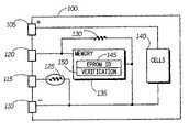
- FIG. 1is an electronic block diagram illustrating a battery for powering an electronic device, in accordance with a preferred embodiment of the present invention.
- FIG. 2is a flowchart illustrating one embodiment of the operation of programming the battery of FIG. 1 .
- FIG. 3illustrates an exemplary embodiment of a memory for use within the battery of FIG. 1 .
- FIG. 4is a block diagram illustrating a battery charger for use with the battery of FIG. 1 .
- FIG. 5is an electronic block diagram illustrating an electronic device for use with the battery of FIG. 1 .
- FIG. 6is an operational flow diagram illustrating an operational sequence of battery authentication of the battery of FIG. 1 .
- the terms “a” or “an”, as used herein,are defined as one or more than one.
- the term plurality, as used herein,is defined as two or more than two.
- the term another, as used herein,is defined as at least a second or more.
- the terms including and/or having, as used herein,are defined as comprising (i.e., open language).
- the term coupled, as used herein,is defined as connected, although not necessarily directly, and not necessarily mechanically.
- program, software application, and the like as used herein,are defined as a sequence of instructions designed for execution on a computer system.
- a program, computer program, or software applicationmay include a subroutine, a function, a procedure, an object method, an object implementation, an executable application, an applet, a servlet, a source code, an object code, a shared library/dynamic load library and/or other sequence of instructions designed for execution on a computer system.
- FIG. 1illustrates a battery (e.g., a battery pack) 100 for powering an electronic device.
- the battery 100includes several contacts for coupling to the battery 100 .
- four contactscan be provided: a positive host contact 105 providing a positive voltage, a negative host contact 110 providing a ground voltage, a thermistor contact 115 for sensing temperature, and a coding contact 120 for use in identifying the battery 100 by a connected electronic device.
- Temperature sensingmay be done with a thermistor 125 within the battery 100 .
- the thermistor 125is used for sensing the temperature of one or more cells 140 .
- the one or more cells 140discharge to provide power to the host electronic device (not shown) and can preferably be recharged by a charger (not shown).
- the battery 100further can include a coding resistor 130 and/or a memory device 135 .
- the optional code resistor 130typically has impedance that corresponds to a particular cell.
- the verification number 150typically is programmed into the battery's EPROM 135 by the manufacturer of the battery 100 and not the EPROM IC 135 manufacturer.
- the verification number 150provides a secure identification to be used for authorization of the battery 100 by a connected electronic device or charger also having knowledge of the KEY.
- an authorized battery manufacturer, the authorized electronic device manufacturer, and the authorized charger manufacturercan have the shared KEY.
- the KEYcan be stored in the electronic device and/or charger for later use and can also be stored in the authorized battery manufacturer's EPROM programming software.
- the EPROM programming softwarecould technically be source code so the manufacturer themselves would not readily identify the KEY code.
- FIG. 2is a flowchart illustrating one exemplary embodiment of the generation of the verification number 150 such as can be accomplished at the battery manufacturer in accordance with the present invention.
- the processbegins with Step 200 in which the programmer reads the EPROM ID number 145 from the memory device 135 .
- the programmercan read the EPROM ID number 145 from the EPROM's ROM space. Note that since this EPROM ID number 145 is in the ROM space it will be fixed at the IC manufacturer and cannot be changed after manufacture of the memory device 135 IC.
- the EPROM ID number 145can be, for example, a serial number for the memory device 135 .
- the ID numbercan be any number associated with the battery, and the number does not have to be stored in the memory device.
- the ID numberis manipulated into an 8 bit number.
- the programmermathematically applies the KEY to the 8 bit manipulated EPROM ID number in step 202 to generate the verification number 150 . This can be accomplished through a series of logical and/or mathematical manipulations such as ‘and’ing, ‘or’ing , adding, subtracting, multiplying, and/or dividing the 8 bit number generated in step 202 with the locally stored KEY.
- the programmerprograms the verification number 150 into the memory device 135 .
- the programmerprograms any other standard parameters such as the fuel bar and associated parameters into the memory device 135 as is well known in the art.
- FIG. 3illustrates an exemplary embodiment of at least a portion of the programmed memory 300 in accordance with the present invention.
- an 8-bit family code 315is stored in the programmed memory 300 .
- the 8-bit family code 315for example, can be a manufacturer specific ID number.
- An 8-Bit CRC code 305is also stored in the programmed memory 300 .
- a 48 bit serial number 310is stored in the programmed memory 300 . This 48 bit serial number can be an identification number for the memory 300 . Any or all of these can be utilized to calculate the verification number 150 as described above.
- FIG. 4is a block diagram of a battery charger 400 suitable for charging the battery 100 of FIG. 1 , in accordance with a preferred embodiment of the present invention.
- the charger 400includes interfaces for coupling to the battery 100 when charging the battery 100 . More particularly, the charger 400 includes a positive interface 405 , a coding interface 410 , a thermistor interface 415 , and a negative interface 420 that are respectively coupled to the positive host contact 105 , the coding contact 120 , the thermistor contact 115 , and the negative host contact 110 of the battery 100 .
- the charger 400further comprises a power supply 425 coupled to a charger circuit 440 which will provide a charging current to the battery 100 via the positive interface 405 connected to an output of the charger circuit 440 .
- the charger 400further includes an analog to digital converter 430 coupled between a microprocessor 435 and the various interfaces to implement battery charging and authentication in accordance with the present invention.
- a ground terminal of the charger 400provides a ground reference to all its components.
- the charger 400further includes the microprocessor 435 for identifying the battery 100 to which the charger 400 is coupled.
- the battery 100can be authenticated by the charger 400 using the microprocessor 435 coupled to the coding interface 410 .
- the microprocessor 435preferably includes memory and is programmed with the KEY as described previously herein. The microprocessor 435 can thus verify the EPROM ID of the battery 100 is a valid EPROM ID by not only comparing it to a known bad EPROM ID lookup table, but also by verifying the verification number 150 (which is based on the EPROM ID) matches the KEY.
- FIG. 5is a block diagram of an electronic device 500 that uses the battery 100 of FIG. 1 , in accordance with a preferred embodiment of the present invention.
- the electronic device 500includes a transceiver 505 , a controller 510 , a memory 515 , a user interface 520 , and a battery connection 525 .
- the transceiver 505is utilized to communicate between the electronic device 500 and other various apparatus.
- the transceiverreceives and transmits various wireless communication signals within a communication system.
- the transceiver 505preferably employs conventional modulation and demodulation techniques for receiving the communication signals transmitted by the communication system to the electronic device 500 .
- the transceiver 505further transmits signals in response to commands from the controller 510 .
- the transceiver 505can be a singular electronic circuit capable of both functions, or alternatively can be an individual receiver circuit and a transmitter circuit.
- the controller 510is further coupled to the memory 515 .
- the memory 515preferably comprise a random access memory (RAM), a read-only memory (ROM), and/or an electrically erasable programmable read-only memory (EEPROM)(not shown), flash memory, or an equivalent.
- RAMrandom access memory
- ROMread-only memory
- EEPROMelectrically erasable programmable read-only memory
- flash memoryor an equivalent.
- the controller 510executes various program steps stored within the memory 515 and further utilizes the data stored within the memory 515 .
- the programs in the memory 515can be hard coded or programmed into the electronic device 500 during manufacturing, can be programmed over-the-air upon customer subscription, or can be downloadable applications. It will be appreciated by one of ordinary skill in the art that other programming methods can be utilized for programming the memory 515 .
- the data stored in the memory 515can be hard coded or programmed into the electronic device 500 during manufacturing, can be programmed over the air upon customer subscription, or can be downloaded. It will be appreciated by one of ordinary skill in the art that other programming methods can be utilized for programming the data into the memory 515 .
- a KEY 530is stored within the memory 515 for use by the controller 510 in the authentication of a battery connected using the battery connection 525 to the electronic device 500 .
- the controller 510is preferably programmed to verify the EPROM ID is a valid EPROM ID by not only comparing it to a known bad EPROM ID lookup table, but also by verifying the verification number which is based on the EPROM ID matches the KEY 530 .
- FIG. 6illustrates an exemplary operational sequence for generating the verification number 150 using the exemplary programmed memory 300 of FIG. 3 by a processor of an attached device such as the charger 400 or the electronic device 500 .
- the processorfor example, can be the microprocessor 435 of the charger 400 or the controller 510 of the electronic device 500 .
- the processorverifies the 8-bit family code 315 for a specific ID number.
- the processorreads the 48-Bit Serial Number 310 .
- Step 610the processor verifies the 8-Bit CRC code 305 .
- Step 615when the CRC is unauthorized in Step 610 or the family code 315 is unauthorized in Step 600 , the charge is disabled.
- Step 620when the CRC is authorized in Step 610 , the processor takes the 48 bit serial number 310 and separates it into 6 distinct 8 Bit sections.
- Step 625the processor manipulates those 6 bytes together by ‘and’ing, ‘or’ing , adding, subtracting, multiplying, and/or dividing them to form a new 8 Bit number.
- Step 630the processor uses this new 8 Bit number and applies the known Key to it to generate a verification number. This can be accomplished through a series of logical and/or mathematical manipulations such as ‘and’ing, ‘or’ing , adding, subtracting, multiplying, and/or dividing the 8 bit number generated in step 625 with the locally stored KEY.
- Step 633the processor checks if the generated verification number matches a predefined number for the battery. If there is no match then the battey is determined unauthorized and, for example, the charging or use of the battery is disabled by the electronic device. On the other hand, in Step 633 , if there is a match, then, in Step 635 , the processor stores the verification number. Next, in Step 640 , the processor recalculates the Checksum based on the new verification number and fuel bar and charge threshold information to be programmed. Next, in Step 645 , all charge and device thresholds are stored. Each unique checksum and the verification number are used to verify that the data is valid and not corrupted thereby assuring safe charging and use of the battery and overall system functionality.
- the present inventioncan be realized in hardware, software, or a combination of hardware and software.
- a system according to a preferred embodiment of the present inventioncan be realized in a centralized fashion in one computer system, or in a distributed fashion where different elements are spread across several interconnected computer systems. Any kind of computer system—or other apparatus adapted for carrying out the methods described herein—is suited.
- a typical combination of hardware and softwarecould be a general-purpose computer system with a computer program that, when being loaded and executed, controls the computer system such that it carries out the methods described herein.
- the present inventioncan also be embedded in a computer program product, which comprises all the features enabling the implementation of the methods described herein, and which—when loaded in a computer system—is able to carry out these methods.
- Computer program means or computer program in the present contextmean any expression, in any language, code or notation, of a set of instructions intended to cause a system having an information processing capability to perform a particular function either directly or after either or both of the following a) conversion to another language, code or, notation; and b) reproduction in a different material form.
- Each computer systemmay include, inter alia, one or more computers and at least a computer readable medium allowing a computer to read data, instructions, messages or message packets, and other computer readable information from the computer readable medium.
- the computer readable mediummay include non-volatile memory, such as ROM, Flash memory, Disk drive memory, CD-ROM, and other permanent storage. Additionally, a computer medium may include, for example, volatile storage such as RAM, buffers, cache memory, and network circuits. Furthermore, the computer readable medium may comprise computer readable information in a transitory state medium such as a network link and/or a network interface, including a wired network or a wireless network, that allow a computer to read such computer readable information.
- a transitory state mediumsuch as a network link and/or a network interface, including a wired network or a wireless network, that allow a computer to read such computer readable information.
Landscapes
- Engineering & Computer Science (AREA)
- Manufacturing & Machinery (AREA)
- Chemical & Material Sciences (AREA)
- Chemical Kinetics & Catalysis (AREA)
- Electrochemistry (AREA)
- General Chemical & Material Sciences (AREA)
- Microelectronics & Electronic Packaging (AREA)
- Charge And Discharge Circuits For Batteries Or The Like (AREA)
Abstract
Description
Claims (18)
Priority Applications (1)
| Application Number | Priority Date | Filing Date | Title |
|---|---|---|---|
| US10/638,621US6972542B2 (en) | 2003-08-11 | 2003-08-11 | System and method for battery verification |
Applications Claiming Priority (1)
| Application Number | Priority Date | Filing Date | Title |
|---|---|---|---|
| US10/638,621US6972542B2 (en) | 2003-08-11 | 2003-08-11 | System and method for battery verification |
Publications (2)
| Publication Number | Publication Date |
|---|---|
| US20050035738A1 US20050035738A1 (en) | 2005-02-17 |
| US6972542B2true US6972542B2 (en) | 2005-12-06 |
Family
ID=34135701
Family Applications (1)
| Application Number | Title | Priority Date | Filing Date |
|---|---|---|---|
| US10/638,621Expired - LifetimeUS6972542B2 (en) | 2003-08-11 | 2003-08-11 | System and method for battery verification |
Country Status (1)
| Country | Link |
|---|---|
| US (1) | US6972542B2 (en) |
Cited By (33)
| Publication number | Priority date | Publication date | Assignee | Title |
|---|---|---|---|---|
| US20040266370A1 (en)* | 2003-04-02 | 2004-12-30 | Celljump Ltd. | Independent application module |
| US20050110463A1 (en)* | 2003-11-26 | 2005-05-26 | Joseph Patino | Charging system and method |
| US20050286928A1 (en)* | 2004-06-23 | 2005-12-29 | Matsushita Electric Industrial Co., Ltd. | Apparatus for electronic component mounting |
| US20060020833A1 (en)* | 2004-07-22 | 2006-01-26 | Dell Products L.P. | Information handling system with power fault protection circuit |
| US20060178170A1 (en)* | 2005-02-08 | 2006-08-10 | Samsung Electronics Co., Ltd. | Wireless communication device having battery authentication, and associated method |
| US20070236183A1 (en)* | 2006-03-31 | 2007-10-11 | Valence Technology, Inc. | Battery charge indication methods, battery charge monitoring devices, rechargeable batteries, and articles of manufacture |
| US20070247112A1 (en)* | 2006-04-18 | 2007-10-25 | Swit Electronic Co., Ltd. | Assembled Lithium-ion Battery Pack with Large Capacity |
| US20070260892A1 (en)* | 2006-05-08 | 2007-11-08 | Paul Christopher R | System and method for authenticating a power source |
| US7317297B1 (en)* | 2004-07-15 | 2008-01-08 | National Semiconductor Corporation | Battery temperature sensor pin used as communication channel |
| US20090045772A1 (en)* | 2007-06-11 | 2009-02-19 | Nigelpower, Llc | Wireless Power System and Proximity Effects |
| US20090295326A1 (en)* | 2008-06-02 | 2009-12-03 | Physio-Control, Inc. | Defibrillator Battery Authentication System |
| US20100078016A1 (en)* | 2008-09-30 | 2010-04-01 | Nellcor Puritan Bennett Llc | Battery management for a breathing assistance system |
| US20100148721A1 (en)* | 2005-10-14 | 2010-06-17 | Research In Motion Limited | Battery pack authentication for a mobile device |
| US20100178961A1 (en)* | 2005-10-14 | 2010-07-15 | Research In Motion Limited | Mobile device with a smart battery |
| US20100197367A1 (en)* | 2005-10-14 | 2010-08-05 | Research In Motion Limited | Interface and communication protocol for a mobile device with a smart battery |
| US20100198287A1 (en)* | 2008-06-02 | 2010-08-05 | Physio-Control, Inc. | Selective recharging of medical device depending on authentication of power adapter system |
| US20100198286A1 (en)* | 2008-06-02 | 2010-08-05 | Physio-Control, Inc. | Selective powering of medical device depending on authentication of power adapter system |
| US20110310519A1 (en)* | 2010-06-17 | 2011-12-22 | Panasonic Corporation | Communication device, power supplying method therefor, and power supply system |
| US20120169270A1 (en)* | 2009-09-16 | 2012-07-05 | Cho Jae-Myung | Battery pack apparatus including a multi-channel 4-terminal network charging apparatus and a multi-channel battery power supply module |
| US8373514B2 (en) | 2007-10-11 | 2013-02-12 | Qualcomm Incorporated | Wireless power transfer using magneto mechanical systems |
| US8378523B2 (en) | 2007-03-02 | 2013-02-19 | Qualcomm Incorporated | Transmitters and receivers for wireless energy transfer |
| US8378522B2 (en) | 2007-03-02 | 2013-02-19 | Qualcomm, Incorporated | Maximizing power yield from wireless power magnetic resonators |
| US8447234B2 (en) | 2006-01-18 | 2013-05-21 | Qualcomm Incorporated | Method and system for powering an electronic device via a wireless link |
| US20130154560A1 (en)* | 2009-11-30 | 2013-06-20 | Broadcom Corporation | Battery with integrated wireless power receiver and/or rfid |
| US8482157B2 (en) | 2007-03-02 | 2013-07-09 | Qualcomm Incorporated | Increasing the Q factor of a resonator |
| US20140000922A1 (en)* | 2007-09-06 | 2014-01-02 | PELLENC (Société Anonyme) | Multifunctional portable electric apparatuses |
| US8629576B2 (en) | 2008-03-28 | 2014-01-14 | Qualcomm Incorporated | Tuning and gain control in electro-magnetic power systems |
| US20140158389A1 (en)* | 2011-07-24 | 2014-06-12 | Makita Corporation | Theft-deterrence system for power tool system, and adapter and method therefor |
| US9008766B2 (en) | 2008-06-02 | 2015-04-14 | Physio-Control, Inc. | Medical device adjusting operation when used with non-authenticated patient parameter collecting accessory |
| US9130602B2 (en) | 2006-01-18 | 2015-09-08 | Qualcomm Incorporated | Method and apparatus for delivering energy to an electrical or electronic device via a wireless link |
| US9601267B2 (en) | 2013-07-03 | 2017-03-21 | Qualcomm Incorporated | Wireless power transmitter with a plurality of magnetic oscillators |
| US9774086B2 (en) | 2007-03-02 | 2017-09-26 | Qualcomm Incorporated | Wireless power apparatus and methods |
| US9916436B2 (en) | 2014-10-24 | 2018-03-13 | Physio-Control, Inc. | Intelligent accessories for medical devices |
Families Citing this family (25)
| Publication number | Priority date | Publication date | Assignee | Title |
|---|---|---|---|---|
| JP2005321983A (en)* | 2004-05-07 | 2005-11-17 | Sony Corp | Electronic equipment, battery pack, and power supply control method and program for electronic equipment |
| JP4457805B2 (en)* | 2004-08-13 | 2010-04-28 | 株式会社ニコン | Electronic device system and electronic camera system |
| CN201515238U (en)* | 2004-10-18 | 2010-06-23 | 布莱克和戴克公司 | Cordless power tool system and battery pack for cordless power tool system |
| JP3765544B1 (en)* | 2004-11-26 | 2006-04-12 | 株式会社ソニー・コンピュータエンタテインメント | Battery and authentication request device |
| JP3838258B2 (en)* | 2005-03-10 | 2006-10-25 | ソニー株式会社 | Battery level display method |
| JP2006324075A (en)* | 2005-05-18 | 2006-11-30 | Matsushita Electric Ind Co Ltd | Battery pack |
| KR100903187B1 (en)* | 2005-06-25 | 2009-06-17 | 주식회사 엘지화학 | Genuine Battery Recognition System for Mobile Devices |
| JP4375318B2 (en)* | 2005-10-12 | 2009-12-02 | ソニー株式会社 | Battery device |
| US20070145945A1 (en)* | 2005-12-28 | 2007-06-28 | Mcginley James W | Method and apparatus to authenticate battery charging device |
| US7622895B1 (en)* | 2006-03-23 | 2009-11-24 | Griffin Technology, Inc. | Power level display calibration device |
| US8863230B1 (en)* | 2006-06-09 | 2014-10-14 | Xilinx, Inc. | Methods of authenticating a programmable integrated circuit in combination with a non-volatile memory device |
| US7987358B1 (en)* | 2006-06-09 | 2011-07-26 | Xilinx, Inc. | Methods of authenticating a user design in a programmable integrated circuit |
| US20080252477A1 (en)* | 2007-04-16 | 2008-10-16 | Motorola, Inc. | Method and apparatus for authenticating use of a battery in a wireless communication device |
| JP5585188B2 (en)* | 2010-04-30 | 2014-09-10 | ソニー株式会社 | Battery module, electric vehicle, and battery module discharge control method |
| DE102010045550A1 (en)* | 2010-09-16 | 2012-03-22 | Festool Gmbh | Control and method for a handheld electric machine tool |
| JP5668424B2 (en)* | 2010-11-16 | 2015-02-12 | ソニー株式会社 | Battery device, battery management system, and battery management method |
| US8898461B2 (en) | 2011-03-03 | 2014-11-25 | Lenovo (Singapore) Pte. Ltd. | Battery authentication method and apparatus |
| US10678905B2 (en)* | 2011-03-18 | 2020-06-09 | Lenovo (Singapore) Pte. Ltd. | Process for controlling battery authentication |
| KR101768723B1 (en)* | 2011-03-30 | 2017-08-17 | 삼성전자주식회사 | Method and system for wireless charging in a portable terminal |
| FR3031628B1 (en) | 2015-01-13 | 2019-07-05 | Commissariat A L'energie Atomique Et Aux Energies Alternatives | ELECTROCHEMICAL BATTERY WITH ELECTRONIC MODULE INTERNAL TO THE HOUSING |
| JP2017073951A (en)* | 2015-10-09 | 2017-04-13 | キヤノン株式会社 | Electronic apparatus and program |
| CN110474081B (en)* | 2018-05-10 | 2022-10-11 | 惠州市德赛电池有限公司 | Lithium ion battery and encryption method thereof |
| CN112995411A (en)* | 2021-02-23 | 2021-06-18 | 西安稳先半导体科技有限责任公司 | Mobile phone power supply safety protection circuit, mobile phone battery assembly and mobile phone |
| CN115834029B (en)* | 2022-01-14 | 2025-07-04 | 宁德时代新能源科技股份有限公司 | Key management method, device, battery management system and storage medium |
| WO2023230136A1 (en)* | 2022-05-24 | 2023-11-30 | Cps Technology Holdings Llc | Battery digital assets, and accountability |
Citations (4)
| Publication number | Priority date | Publication date | Assignee | Title |
|---|---|---|---|---|
| US5717307A (en) | 1996-07-24 | 1998-02-10 | Motorola, Inc. | Apparatus and method for identifying the type and brand of a battery for a portable device |
| US5717306A (en)* | 1994-11-18 | 1998-02-10 | Shipp; John I. | Battery identification and power interrupt system |
| US5939856A (en) | 1997-05-30 | 1999-08-17 | Motorola, Inc. | Battery and charging system using switchable coding devices |
| US6291966B1 (en)* | 1999-01-27 | 2001-09-18 | Telefonaktiebolaget Lm Ericsson | Method and an apparatus for storing and communicating battery information |
- 2003
- 2003-08-11USUS10/638,621patent/US6972542B2/ennot_activeExpired - Lifetime
Patent Citations (4)
| Publication number | Priority date | Publication date | Assignee | Title |
|---|---|---|---|---|
| US5717306A (en)* | 1994-11-18 | 1998-02-10 | Shipp; John I. | Battery identification and power interrupt system |
| US5717307A (en) | 1996-07-24 | 1998-02-10 | Motorola, Inc. | Apparatus and method for identifying the type and brand of a battery for a portable device |
| US5939856A (en) | 1997-05-30 | 1999-08-17 | Motorola, Inc. | Battery and charging system using switchable coding devices |
| US6291966B1 (en)* | 1999-01-27 | 2001-09-18 | Telefonaktiebolaget Lm Ericsson | Method and an apparatus for storing and communicating battery information |
Non-Patent Citations (1)
| Title |
|---|
| "Motorola Announces Availability of New Wireless Phone Batteries for Increased Performance and Safety, Featuring New Hologram Design; Each Battery with Hologram Image Clearly Identifies Item as a Motorola Original(TM) Accessory-Not a Counterfeit or Imitation Battery", Libertyville, Ill, Jul. 23, 1998. |
Cited By (59)
| Publication number | Priority date | Publication date | Assignee | Title |
|---|---|---|---|---|
| US20040266370A1 (en)* | 2003-04-02 | 2004-12-30 | Celljump Ltd. | Independent application module |
| US20050110463A1 (en)* | 2003-11-26 | 2005-05-26 | Joseph Patino | Charging system and method |
| US7626365B2 (en)* | 2003-11-26 | 2009-12-01 | Motorola Inc. | Charging system and method |
| US20050286928A1 (en)* | 2004-06-23 | 2005-12-29 | Matsushita Electric Industrial Co., Ltd. | Apparatus for electronic component mounting |
| US7317297B1 (en)* | 2004-07-15 | 2008-01-08 | National Semiconductor Corporation | Battery temperature sensor pin used as communication channel |
| US20060020833A1 (en)* | 2004-07-22 | 2006-01-26 | Dell Products L.P. | Information handling system with power fault protection circuit |
| US7363518B2 (en)* | 2004-07-22 | 2008-04-22 | Dell Products L.P. | Information handling system with power fault protection circuit |
| US20060178170A1 (en)* | 2005-02-08 | 2006-08-10 | Samsung Electronics Co., Ltd. | Wireless communication device having battery authentication, and associated method |
| US8670799B2 (en) | 2005-10-14 | 2014-03-11 | Blackberry Limited | Interface and communication protocol for a mobile device with a smart battery |
| US20100178961A1 (en)* | 2005-10-14 | 2010-07-15 | Research In Motion Limited | Mobile device with a smart battery |
| US8278870B2 (en) | 2005-10-14 | 2012-10-02 | Research In Motion Limited | Battery pack authentication for a mobile communication device |
| US8280439B2 (en) | 2005-10-14 | 2012-10-02 | Research In Motion Limited | Interface and communication protocol for a mobile device with a smart battery |
| US8285327B2 (en)* | 2005-10-14 | 2012-10-09 | Research In Motion Limited | Interface and communication protocol for a mobile communication device with a smart battery |
| US8639219B2 (en) | 2005-10-14 | 2014-01-28 | Blackberry Limited | Battery pack authentication for a mobile communication device |
| US8032187B2 (en) | 2005-10-14 | 2011-10-04 | Research In Motion Limited | Mobile device with a smart battery having a battery information profile corresponding to a communication standard |
| US8554284B2 (en) | 2005-10-14 | 2013-10-08 | Blackberry Limited | Mobile device with a smart battery having a battery information profile corresponding to a communication standard |
| US20100148721A1 (en)* | 2005-10-14 | 2010-06-17 | Research In Motion Limited | Battery pack authentication for a mobile device |
| US8280454B2 (en) | 2005-10-14 | 2012-10-02 | Research In Motion Limited | Mobile device with a smart battery having a battery information profile corresponding to a communication standard |
| US20100197367A1 (en)* | 2005-10-14 | 2010-08-05 | Research In Motion Limited | Interface and communication protocol for a mobile device with a smart battery |
| US8543162B2 (en) | 2005-10-14 | 2013-09-24 | Blackberry Limited | Interface and communication protocol for a mobile device with a smart battery |
| US20100197366A1 (en)* | 2005-10-14 | 2010-08-05 | Research In Motion Limited | Interface and communication protocol for a mobile device with a smart battery |
| US8447234B2 (en) | 2006-01-18 | 2013-05-21 | Qualcomm Incorporated | Method and system for powering an electronic device via a wireless link |
| US9130602B2 (en) | 2006-01-18 | 2015-09-08 | Qualcomm Incorporated | Method and apparatus for delivering energy to an electrical or electronic device via a wireless link |
| US7723958B2 (en)* | 2006-03-31 | 2010-05-25 | Valence Technology, Inc. | Battery charge indication methods, battery charge monitoring devices, rechargeable batteries, and articles of manufacture |
| US20070236183A1 (en)* | 2006-03-31 | 2007-10-11 | Valence Technology, Inc. | Battery charge indication methods, battery charge monitoring devices, rechargeable batteries, and articles of manufacture |
| US20070247112A1 (en)* | 2006-04-18 | 2007-10-25 | Swit Electronic Co., Ltd. | Assembled Lithium-ion Battery Pack with Large Capacity |
| US20070260892A1 (en)* | 2006-05-08 | 2007-11-08 | Paul Christopher R | System and method for authenticating a power source |
| US8378522B2 (en) | 2007-03-02 | 2013-02-19 | Qualcomm, Incorporated | Maximizing power yield from wireless power magnetic resonators |
| US8482157B2 (en) | 2007-03-02 | 2013-07-09 | Qualcomm Incorporated | Increasing the Q factor of a resonator |
| US9774086B2 (en) | 2007-03-02 | 2017-09-26 | Qualcomm Incorporated | Wireless power apparatus and methods |
| US8378523B2 (en) | 2007-03-02 | 2013-02-19 | Qualcomm Incorporated | Transmitters and receivers for wireless energy transfer |
| US20090045772A1 (en)* | 2007-06-11 | 2009-02-19 | Nigelpower, Llc | Wireless Power System and Proximity Effects |
| US9124120B2 (en) | 2007-06-11 | 2015-09-01 | Qualcomm Incorporated | Wireless power system and proximity effects |
| US20140000922A1 (en)* | 2007-09-06 | 2014-01-02 | PELLENC (Société Anonyme) | Multifunctional portable electric apparatuses |
| US8373514B2 (en) | 2007-10-11 | 2013-02-12 | Qualcomm Incorporated | Wireless power transfer using magneto mechanical systems |
| US8629576B2 (en) | 2008-03-28 | 2014-01-14 | Qualcomm Incorporated | Tuning and gain control in electro-magnetic power systems |
| US20100198286A1 (en)* | 2008-06-02 | 2010-08-05 | Physio-Control, Inc. | Selective powering of medical device depending on authentication of power adapter system |
| US9008766B2 (en) | 2008-06-02 | 2015-04-14 | Physio-Control, Inc. | Medical device adjusting operation when used with non-authenticated patient parameter collecting accessory |
| US20100198287A1 (en)* | 2008-06-02 | 2010-08-05 | Physio-Control, Inc. | Selective recharging of medical device depending on authentication of power adapter system |
| US7728548B2 (en) | 2008-06-02 | 2010-06-01 | Physio-Control, Inc. | Defibrillator battery authentication system |
| USRE49764E1 (en) | 2008-06-02 | 2023-12-26 | Physio-Control, Inc. | Medical device adjusting operation when used with non-authenticated patient parameter collecting accessory |
| US9907971B2 (en) | 2008-06-02 | 2018-03-06 | Physio-Control, Inc. | Medical device adjusting operation when used with non-authenticated patient parameter collecting accessory |
| US8183823B2 (en) | 2008-06-02 | 2012-05-22 | Physio-Control, Inc. | Selective powering of medical device depending on authentication of power adapter system |
| US20090295326A1 (en)* | 2008-06-02 | 2009-12-03 | Physio-Control, Inc. | Defibrillator Battery Authentication System |
| US9339661B2 (en) | 2008-06-02 | 2016-05-17 | Physio-Control, Inc. | Medical device adjusting operation when used with non-authenticated patient parameter collecting accessory |
| US8179087B2 (en) | 2008-06-02 | 2012-05-15 | Physio-Control, Inc. | Selective recharging of medical device depending on authentication of power adapter system |
| US20100078016A1 (en)* | 2008-09-30 | 2010-04-01 | Nellcor Puritan Bennett Llc | Battery management for a breathing assistance system |
| US8302600B2 (en) | 2008-09-30 | 2012-11-06 | Nellcor Puritan Bennett Llc | Battery management for a breathing assistance system |
| US9269990B2 (en) | 2008-09-30 | 2016-02-23 | Covidien Lp | Battery management for a breathing assistance system |
| US20120169270A1 (en)* | 2009-09-16 | 2012-07-05 | Cho Jae-Myung | Battery pack apparatus including a multi-channel 4-terminal network charging apparatus and a multi-channel battery power supply module |
| US8716977B2 (en)* | 2009-11-30 | 2014-05-06 | Broadcom Corporation | Battery with integrated wireless power receiver and/or RFID |
| US20130154560A1 (en)* | 2009-11-30 | 2013-06-20 | Broadcom Corporation | Battery with integrated wireless power receiver and/or rfid |
| US8724277B2 (en)* | 2010-06-17 | 2014-05-13 | Panasonic Corporation | Communication device, power supplying method therefor, and power supply system |
| US20110310519A1 (en)* | 2010-06-17 | 2011-12-22 | Panasonic Corporation | Communication device, power supplying method therefor, and power supply system |
| US20140158389A1 (en)* | 2011-07-24 | 2014-06-12 | Makita Corporation | Theft-deterrence system for power tool system, and adapter and method therefor |
| US10124455B2 (en)* | 2011-07-24 | 2018-11-13 | Makita Corporation | Theft-deterrence system for power tool system, and adapter and method therefor |
| US9601267B2 (en) | 2013-07-03 | 2017-03-21 | Qualcomm Incorporated | Wireless power transmitter with a plurality of magnetic oscillators |
| US9916436B2 (en) | 2014-10-24 | 2018-03-13 | Physio-Control, Inc. | Intelligent accessories for medical devices |
| US10839068B2 (en) | 2014-10-24 | 2020-11-17 | Physio-Control, Inc. | Medical devices with intelligent accessories |
Also Published As
| Publication number | Publication date |
|---|---|
| US20050035738A1 (en) | 2005-02-17 |
Similar Documents
| Publication | Publication Date | Title |
|---|---|---|
| US6972542B2 (en) | System and method for battery verification | |
| US7512795B2 (en) | Method and apparatus for authenticating components | |
| KR101109935B1 (en) | Method and apparatus for authenticating a mobile phone accessory | |
| US7498766B2 (en) | System and method for authenticating a battery | |
| US7949872B2 (en) | Battery and authentication requesting device | |
| AU2003204376B2 (en) | Use of hashing in a secure boot loader | |
| US8424092B2 (en) | Electronic apparatus for authenticating a battery pack | |
| US8051285B2 (en) | Battery processor circuitry with separate public and private bus | |
| US20070260892A1 (en) | System and method for authenticating a power source | |
| JP2009272299A (en) | Battery authentication system, electronic equipment, battery, and battery charger | |
| JP2007060353A (en) | Portable telephone device, portable telephone system, power supply unit, power supply authentication method and program | |
| JP2007035479A (en) | Battery pack and battery-pack-dedicated device | |
| JP2009015744A (en) | Authentication system and authentication device | |
| US7770791B2 (en) | Security device | |
| AU2005234740B2 (en) | Battery pack, charging control method, and application device | |
| CN1810016A (en) | Anti-theft system for mobile electronic devices | |
| WO2025087202A1 (en) | Anti-disassembly circuit, control method, and interphone | |
| CN100465889C (en) | Method for downloading computer data to mobile phone | |
| JP2013207459A (en) | Portable terminal and control method of the same | |
| KR101088074B1 (en) | Mobile communication terminal with genuine battery identification function and control method | |
| CN101582770A (en) | Authentication system, authentication target device and control method thereof | |
| CN118646116A (en) | Battery protection circuit, battery protection board, electronic device and control method | |
| JPH11275650A (en) | Mobile phone terminal with unauthorized use prevention function |
Legal Events
| Date | Code | Title | Description |
|---|---|---|---|
| AS | Assignment | Owner name:MOTOROLA, INC., ILLINOIS Free format text:ASSIGNMENT OF ASSIGNORS INTEREST;ASSIGNORS:PATINO, JOSEPH;BURTON, ANDREW F.;FRASER, RANDALL S.;REEL/FRAME:014398/0145 Effective date:20030807 | |
| STCF | Information on status: patent grant | Free format text:PATENTED CASE | |
| FPAY | Fee payment | Year of fee payment:4 | |
| AS | Assignment | Owner name:MOTOROLA MOBILITY, INC, ILLINOIS Free format text:ASSIGNMENT OF ASSIGNORS INTEREST;ASSIGNOR:MOTOROLA, INC;REEL/FRAME:025673/0558 Effective date:20100731 | |
| AS | Assignment | Owner name:MOTOROLA MOBILITY LLC, ILLINOIS Free format text:CHANGE OF NAME;ASSIGNOR:MOTOROLA MOBILITY, INC.;REEL/FRAME:029216/0282 Effective date:20120622 | |
| FPAY | Fee payment | Year of fee payment:8 | |
| AS | Assignment | Owner name:GOOGLE TECHNOLOGY HOLDINGS LLC, CALIFORNIA Free format text:ASSIGNMENT OF ASSIGNORS INTEREST;ASSIGNOR:MOTOROLA MOBILITY LLC;REEL/FRAME:034316/0001 Effective date:20141028 | |
| FPAY | Fee payment | Year of fee payment:12 |