US6972039B2 - Floating bearing knee joint prosthesis with a fixed tibial post - Google Patents
Floating bearing knee joint prosthesis with a fixed tibial postDownload PDFInfo
- Publication number
- US6972039B2 US6972039B2US10/188,305US18830502AUS6972039B2US 6972039 B2US6972039 B2US 6972039B2US 18830502 AUS18830502 AUS 18830502AUS 6972039 B2US6972039 B2US 6972039B2
- Authority
- US
- United States
- Prior art keywords
- component
- bearing
- guide post
- tibial
- condylar
- Prior art date
- Legal status (The legal status is an assumption and is not a legal conclusion. Google has not performed a legal analysis and makes no representation as to the accuracy of the status listed.)
- Expired - Lifetime, expires
Links
- 210000000629knee jointAnatomy0.000titleclaimsdescription103
- 241000469816VarusSpecies0.000claimsabstractdescription39
- 241001227561ValgusSpecies0.000claimsabstractdescription37
- 210000002303tibiaAnatomy0.000claimsdescription36
- 210000000689upper legAnatomy0.000claimsdescription32
- 239000000463materialSubstances0.000claimsdescription24
- 229920000642polymerPolymers0.000claimsdescription16
- 210000003127kneeAnatomy0.000abstractdescription74
- 230000033001locomotionEffects0.000description38
- 230000036961partial effectEffects0.000description9
- 230000002093peripheral effectEffects0.000description9
- -1polyethylenePolymers0.000description9
- 239000004698PolyethyleneSubstances0.000description8
- 229910052751metalInorganic materials0.000description8
- 239000002184metalSubstances0.000description8
- 229920000573polyethylenePolymers0.000description8
- 210000004872soft tissueAnatomy0.000description8
- 239000004699Ultra-high molecular weight polyethyleneSubstances0.000description7
- 229920000785ultra high molecular weight polyethylenePolymers0.000description7
- MTHLBYMFGWSRME-UHFFFAOYSA-N[Cr].[Co].[Mo]Chemical compound[Cr].[Co].[Mo]MTHLBYMFGWSRME-UHFFFAOYSA-N0.000description6
- 230000001965increasing effectEffects0.000description6
- 210000004417patellaAnatomy0.000description6
- 210000003041ligamentAnatomy0.000description5
- 230000002829reductive effectEffects0.000description5
- 239000000919ceramicSubstances0.000description4
- 239000000788chromium alloySubstances0.000description4
- 230000006866deteriorationEffects0.000description4
- 238000002513implantationMethods0.000description4
- RTAQQCXQSZGOHL-UHFFFAOYSA-NTitaniumChemical compound[Ti]RTAQQCXQSZGOHL-UHFFFAOYSA-N0.000description3
- 210000000988bone and boneAnatomy0.000description3
- 230000000694effectsEffects0.000description3
- 230000005021gaitEffects0.000description3
- 239000007943implantSubstances0.000description3
- 230000013011matingEffects0.000description3
- 230000007246mechanismEffects0.000description3
- 238000000034methodMethods0.000description3
- 210000003205muscleAnatomy0.000description3
- 230000000087stabilizing effectEffects0.000description3
- 239000010936titaniumSubstances0.000description3
- 229910052719titaniumInorganic materials0.000description3
- 229910045601alloyInorganic materials0.000description2
- 239000000956alloySubstances0.000description2
- 239000000560biocompatible materialSubstances0.000description2
- 210000004439collateral ligamentAnatomy0.000description2
- 238000006073displacement reactionMethods0.000description2
- 210000005069earsAnatomy0.000description2
- 229920003023plasticPolymers0.000description2
- 239000004033plasticSubstances0.000description2
- 238000002271resectionMethods0.000description2
- 230000000284resting effectEffects0.000description2
- 210000002435tendonAnatomy0.000description2
- 239000000602vitalliumSubstances0.000description2
- 235000014443Pyrus communisNutrition0.000description1
- 210000001264anterior cruciate ligamentAnatomy0.000description1
- 230000003190augmentative effectEffects0.000description1
- 230000008859changeEffects0.000description1
- 230000009194climbingEffects0.000description1
- 239000011248coating agentSubstances0.000description1
- 238000000576coating methodMethods0.000description1
- 230000000295complement effectEffects0.000description1
- 230000006835compressionEffects0.000description1
- 238000007906compressionMethods0.000description1
- 230000001010compromised effectEffects0.000description1
- 239000012141concentrateSubstances0.000description1
- 230000003247decreasing effectEffects0.000description1
- 229910003460diamondInorganic materials0.000description1
- 239000010432diamondSubstances0.000description1
- 230000002708enhancing effectEffects0.000description1
- 210000002082fibulaAnatomy0.000description1
- 238000013150knee replacementMethods0.000description1
- 230000014759maintenance of locationEffects0.000description1
- 229910001092metal group alloyInorganic materials0.000description1
- 150000002739metalsChemical class0.000description1
- 238000012986modificationMethods0.000description1
- 230000004048modificationEffects0.000description1
- 230000007935neutral effectEffects0.000description1
- 210000002967posterior cruciate ligamentAnatomy0.000description1
- 238000002360preparation methodMethods0.000description1
- 230000009467reductionEffects0.000description1
- 230000006641stabilisationEffects0.000description1
- 238000011105stabilizationMethods0.000description1
Images


Classifications
- A—HUMAN NECESSITIES
- A61—MEDICAL OR VETERINARY SCIENCE; HYGIENE
- A61F—FILTERS IMPLANTABLE INTO BLOOD VESSELS; PROSTHESES; DEVICES PROVIDING PATENCY TO, OR PREVENTING COLLAPSING OF, TUBULAR STRUCTURES OF THE BODY, e.g. STENTS; ORTHOPAEDIC, NURSING OR CONTRACEPTIVE DEVICES; FOMENTATION; TREATMENT OR PROTECTION OF EYES OR EARS; BANDAGES, DRESSINGS OR ABSORBENT PADS; FIRST-AID KITS
- A61F2/00—Filters implantable into blood vessels; Prostheses, i.e. artificial substitutes or replacements for parts of the body; Appliances for connecting them with the body; Devices providing patency to, or preventing collapsing of, tubular structures of the body, e.g. stents
- A61F2/02—Prostheses implantable into the body
- A61F2/30—Joints
- A61F2/38—Joints for elbows or knees
- A61F2/3868—Joints for elbows or knees with sliding tibial bearing
- A—HUMAN NECESSITIES
- A61—MEDICAL OR VETERINARY SCIENCE; HYGIENE
- A61F—FILTERS IMPLANTABLE INTO BLOOD VESSELS; PROSTHESES; DEVICES PROVIDING PATENCY TO, OR PREVENTING COLLAPSING OF, TUBULAR STRUCTURES OF THE BODY, e.g. STENTS; ORTHOPAEDIC, NURSING OR CONTRACEPTIVE DEVICES; FOMENTATION; TREATMENT OR PROTECTION OF EYES OR EARS; BANDAGES, DRESSINGS OR ABSORBENT PADS; FIRST-AID KITS
- A61F2/00—Filters implantable into blood vessels; Prostheses, i.e. artificial substitutes or replacements for parts of the body; Appliances for connecting them with the body; Devices providing patency to, or preventing collapsing of, tubular structures of the body, e.g. stents
- A61F2/02—Prostheses implantable into the body
- A61F2/30—Joints
- A61F2/38—Joints for elbows or knees
- A61F2/3886—Joints for elbows or knees for stabilising knees against anterior or lateral dislocations
- A—HUMAN NECESSITIES
- A61—MEDICAL OR VETERINARY SCIENCE; HYGIENE
- A61F—FILTERS IMPLANTABLE INTO BLOOD VESSELS; PROSTHESES; DEVICES PROVIDING PATENCY TO, OR PREVENTING COLLAPSING OF, TUBULAR STRUCTURES OF THE BODY, e.g. STENTS; ORTHOPAEDIC, NURSING OR CONTRACEPTIVE DEVICES; FOMENTATION; TREATMENT OR PROTECTION OF EYES OR EARS; BANDAGES, DRESSINGS OR ABSORBENT PADS; FIRST-AID KITS
- A61F2/00—Filters implantable into blood vessels; Prostheses, i.e. artificial substitutes or replacements for parts of the body; Appliances for connecting them with the body; Devices providing patency to, or preventing collapsing of, tubular structures of the body, e.g. stents
- A61F2/02—Prostheses implantable into the body
- A61F2/30—Joints
- A61F2/38—Joints for elbows or knees
- A61F2/3859—Femoral components
- A—HUMAN NECESSITIES
- A61—MEDICAL OR VETERINARY SCIENCE; HYGIENE
- A61F—FILTERS IMPLANTABLE INTO BLOOD VESSELS; PROSTHESES; DEVICES PROVIDING PATENCY TO, OR PREVENTING COLLAPSING OF, TUBULAR STRUCTURES OF THE BODY, e.g. STENTS; ORTHOPAEDIC, NURSING OR CONTRACEPTIVE DEVICES; FOMENTATION; TREATMENT OR PROTECTION OF EYES OR EARS; BANDAGES, DRESSINGS OR ABSORBENT PADS; FIRST-AID KITS
- A61F2/00—Filters implantable into blood vessels; Prostheses, i.e. artificial substitutes or replacements for parts of the body; Appliances for connecting them with the body; Devices providing patency to, or preventing collapsing of, tubular structures of the body, e.g. stents
- A61F2/02—Prostheses implantable into the body
- A61F2/30—Joints
- A61F2/38—Joints for elbows or knees
- A61F2/389—Tibial components
- A—HUMAN NECESSITIES
- A61—MEDICAL OR VETERINARY SCIENCE; HYGIENE
- A61F—FILTERS IMPLANTABLE INTO BLOOD VESSELS; PROSTHESES; DEVICES PROVIDING PATENCY TO, OR PREVENTING COLLAPSING OF, TUBULAR STRUCTURES OF THE BODY, e.g. STENTS; ORTHOPAEDIC, NURSING OR CONTRACEPTIVE DEVICES; FOMENTATION; TREATMENT OR PROTECTION OF EYES OR EARS; BANDAGES, DRESSINGS OR ABSORBENT PADS; FIRST-AID KITS
- A61F2/00—Filters implantable into blood vessels; Prostheses, i.e. artificial substitutes or replacements for parts of the body; Appliances for connecting them with the body; Devices providing patency to, or preventing collapsing of, tubular structures of the body, e.g. stents
- A61F2/02—Prostheses implantable into the body
- A61F2/30—Joints
- A61F2002/30001—Additional features of subject-matter classified in A61F2/28, A61F2/30 and subgroups thereof
- A61F2002/30003—Material related properties of the prosthesis or of a coating on the prosthesis
- A61F2002/3006—Properties of materials and coating materials
- A61F2002/3009—Transparent or translucent
- A—HUMAN NECESSITIES
- A61—MEDICAL OR VETERINARY SCIENCE; HYGIENE
- A61F—FILTERS IMPLANTABLE INTO BLOOD VESSELS; PROSTHESES; DEVICES PROVIDING PATENCY TO, OR PREVENTING COLLAPSING OF, TUBULAR STRUCTURES OF THE BODY, e.g. STENTS; ORTHOPAEDIC, NURSING OR CONTRACEPTIVE DEVICES; FOMENTATION; TREATMENT OR PROTECTION OF EYES OR EARS; BANDAGES, DRESSINGS OR ABSORBENT PADS; FIRST-AID KITS
- A61F2/00—Filters implantable into blood vessels; Prostheses, i.e. artificial substitutes or replacements for parts of the body; Appliances for connecting them with the body; Devices providing patency to, or preventing collapsing of, tubular structures of the body, e.g. stents
- A61F2/02—Prostheses implantable into the body
- A61F2/30—Joints
- A61F2002/30001—Additional features of subject-matter classified in A61F2/28, A61F2/30 and subgroups thereof
- A61F2002/30003—Material related properties of the prosthesis or of a coating on the prosthesis
- A61F2002/3006—Properties of materials and coating materials
- A61F2002/30092—Properties of materials and coating materials using shape memory or superelastic materials, e.g. nitinol
- A—HUMAN NECESSITIES
- A61—MEDICAL OR VETERINARY SCIENCE; HYGIENE
- A61F—FILTERS IMPLANTABLE INTO BLOOD VESSELS; PROSTHESES; DEVICES PROVIDING PATENCY TO, OR PREVENTING COLLAPSING OF, TUBULAR STRUCTURES OF THE BODY, e.g. STENTS; ORTHOPAEDIC, NURSING OR CONTRACEPTIVE DEVICES; FOMENTATION; TREATMENT OR PROTECTION OF EYES OR EARS; BANDAGES, DRESSINGS OR ABSORBENT PADS; FIRST-AID KITS
- A61F2/00—Filters implantable into blood vessels; Prostheses, i.e. artificial substitutes or replacements for parts of the body; Appliances for connecting them with the body; Devices providing patency to, or preventing collapsing of, tubular structures of the body, e.g. stents
- A61F2/02—Prostheses implantable into the body
- A61F2/30—Joints
- A61F2002/30001—Additional features of subject-matter classified in A61F2/28, A61F2/30 and subgroups thereof
- A61F2002/30108—Shapes
- A61F2002/3011—Cross-sections or two-dimensional shapes
- A61F2002/30112—Rounded shapes, e.g. with rounded corners
- A61F2002/30133—Rounded shapes, e.g. with rounded corners kidney-shaped or bean-shaped
- A—HUMAN NECESSITIES
- A61—MEDICAL OR VETERINARY SCIENCE; HYGIENE
- A61F—FILTERS IMPLANTABLE INTO BLOOD VESSELS; PROSTHESES; DEVICES PROVIDING PATENCY TO, OR PREVENTING COLLAPSING OF, TUBULAR STRUCTURES OF THE BODY, e.g. STENTS; ORTHOPAEDIC, NURSING OR CONTRACEPTIVE DEVICES; FOMENTATION; TREATMENT OR PROTECTION OF EYES OR EARS; BANDAGES, DRESSINGS OR ABSORBENT PADS; FIRST-AID KITS
- A61F2/00—Filters implantable into blood vessels; Prostheses, i.e. artificial substitutes or replacements for parts of the body; Appliances for connecting them with the body; Devices providing patency to, or preventing collapsing of, tubular structures of the body, e.g. stents
- A61F2/02—Prostheses implantable into the body
- A61F2/30—Joints
- A61F2002/30001—Additional features of subject-matter classified in A61F2/28, A61F2/30 and subgroups thereof
- A61F2002/30108—Shapes
- A61F2002/3011—Cross-sections or two-dimensional shapes
- A61F2002/30138—Convex polygonal shapes
- A61F2002/30153—Convex polygonal shapes rectangular
- A—HUMAN NECESSITIES
- A61—MEDICAL OR VETERINARY SCIENCE; HYGIENE
- A61F—FILTERS IMPLANTABLE INTO BLOOD VESSELS; PROSTHESES; DEVICES PROVIDING PATENCY TO, OR PREVENTING COLLAPSING OF, TUBULAR STRUCTURES OF THE BODY, e.g. STENTS; ORTHOPAEDIC, NURSING OR CONTRACEPTIVE DEVICES; FOMENTATION; TREATMENT OR PROTECTION OF EYES OR EARS; BANDAGES, DRESSINGS OR ABSORBENT PADS; FIRST-AID KITS
- A61F2/00—Filters implantable into blood vessels; Prostheses, i.e. artificial substitutes or replacements for parts of the body; Appliances for connecting them with the body; Devices providing patency to, or preventing collapsing of, tubular structures of the body, e.g. stents
- A61F2/02—Prostheses implantable into the body
- A61F2/30—Joints
- A61F2002/30001—Additional features of subject-matter classified in A61F2/28, A61F2/30 and subgroups thereof
- A61F2002/30316—The prosthesis having different structural features at different locations within the same prosthesis; Connections between prosthetic parts; Special structural features of bone or joint prostheses not otherwise provided for
- A61F2002/30329—Connections or couplings between prosthetic parts, e.g. between modular parts; Connecting elements
- A61F2002/30448—Connections or couplings between prosthetic parts, e.g. between modular parts; Connecting elements using adhesives
- A—HUMAN NECESSITIES
- A61—MEDICAL OR VETERINARY SCIENCE; HYGIENE
- A61F—FILTERS IMPLANTABLE INTO BLOOD VESSELS; PROSTHESES; DEVICES PROVIDING PATENCY TO, OR PREVENTING COLLAPSING OF, TUBULAR STRUCTURES OF THE BODY, e.g. STENTS; ORTHOPAEDIC, NURSING OR CONTRACEPTIVE DEVICES; FOMENTATION; TREATMENT OR PROTECTION OF EYES OR EARS; BANDAGES, DRESSINGS OR ABSORBENT PADS; FIRST-AID KITS
- A61F2/00—Filters implantable into blood vessels; Prostheses, i.e. artificial substitutes or replacements for parts of the body; Appliances for connecting them with the body; Devices providing patency to, or preventing collapsing of, tubular structures of the body, e.g. stents
- A61F2/02—Prostheses implantable into the body
- A61F2/30—Joints
- A61F2002/30001—Additional features of subject-matter classified in A61F2/28, A61F2/30 and subgroups thereof
- A61F2002/30316—The prosthesis having different structural features at different locations within the same prosthesis; Connections between prosthetic parts; Special structural features of bone or joint prostheses not otherwise provided for
- A61F2002/30535—Special structural features of bone or joint prostheses not otherwise provided for
- A61F2002/30561—Special structural features of bone or joint prostheses not otherwise provided for breakable or frangible
- A—HUMAN NECESSITIES
- A61—MEDICAL OR VETERINARY SCIENCE; HYGIENE
- A61F—FILTERS IMPLANTABLE INTO BLOOD VESSELS; PROSTHESES; DEVICES PROVIDING PATENCY TO, OR PREVENTING COLLAPSING OF, TUBULAR STRUCTURES OF THE BODY, e.g. STENTS; ORTHOPAEDIC, NURSING OR CONTRACEPTIVE DEVICES; FOMENTATION; TREATMENT OR PROTECTION OF EYES OR EARS; BANDAGES, DRESSINGS OR ABSORBENT PADS; FIRST-AID KITS
- A61F2/00—Filters implantable into blood vessels; Prostheses, i.e. artificial substitutes or replacements for parts of the body; Appliances for connecting them with the body; Devices providing patency to, or preventing collapsing of, tubular structures of the body, e.g. stents
- A61F2/02—Prostheses implantable into the body
- A61F2/30—Joints
- A61F2002/30001—Additional features of subject-matter classified in A61F2/28, A61F2/30 and subgroups thereof
- A61F2002/30316—The prosthesis having different structural features at different locations within the same prosthesis; Connections between prosthetic parts; Special structural features of bone or joint prostheses not otherwise provided for
- A61F2002/30535—Special structural features of bone or joint prostheses not otherwise provided for
- A61F2002/30589—Sealing means
- A—HUMAN NECESSITIES
- A61—MEDICAL OR VETERINARY SCIENCE; HYGIENE
- A61F—FILTERS IMPLANTABLE INTO BLOOD VESSELS; PROSTHESES; DEVICES PROVIDING PATENCY TO, OR PREVENTING COLLAPSING OF, TUBULAR STRUCTURES OF THE BODY, e.g. STENTS; ORTHOPAEDIC, NURSING OR CONTRACEPTIVE DEVICES; FOMENTATION; TREATMENT OR PROTECTION OF EYES OR EARS; BANDAGES, DRESSINGS OR ABSORBENT PADS; FIRST-AID KITS
- A61F2/00—Filters implantable into blood vessels; Prostheses, i.e. artificial substitutes or replacements for parts of the body; Appliances for connecting them with the body; Devices providing patency to, or preventing collapsing of, tubular structures of the body, e.g. stents
- A61F2/02—Prostheses implantable into the body
- A61F2/30—Joints
- A61F2002/30001—Additional features of subject-matter classified in A61F2/28, A61F2/30 and subgroups thereof
- A61F2002/30316—The prosthesis having different structural features at different locations within the same prosthesis; Connections between prosthetic parts; Special structural features of bone or joint prostheses not otherwise provided for
- A61F2002/30535—Special structural features of bone or joint prostheses not otherwise provided for
- A61F2002/30604—Special structural features of bone or joint prostheses not otherwise provided for modular
- A—HUMAN NECESSITIES
- A61—MEDICAL OR VETERINARY SCIENCE; HYGIENE
- A61F—FILTERS IMPLANTABLE INTO BLOOD VESSELS; PROSTHESES; DEVICES PROVIDING PATENCY TO, OR PREVENTING COLLAPSING OF, TUBULAR STRUCTURES OF THE BODY, e.g. STENTS; ORTHOPAEDIC, NURSING OR CONTRACEPTIVE DEVICES; FOMENTATION; TREATMENT OR PROTECTION OF EYES OR EARS; BANDAGES, DRESSINGS OR ABSORBENT PADS; FIRST-AID KITS
- A61F2/00—Filters implantable into blood vessels; Prostheses, i.e. artificial substitutes or replacements for parts of the body; Appliances for connecting them with the body; Devices providing patency to, or preventing collapsing of, tubular structures of the body, e.g. stents
- A61F2/02—Prostheses implantable into the body
- A61F2/30—Joints
- A61F2002/30001—Additional features of subject-matter classified in A61F2/28, A61F2/30 and subgroups thereof
- A61F2002/30667—Features concerning an interaction with the environment or a particular use of the prosthesis
- A61F2002/30682—Means for preventing migration of particles released by the joint, e.g. wear debris or cement particles
- A—HUMAN NECESSITIES
- A61—MEDICAL OR VETERINARY SCIENCE; HYGIENE
- A61F—FILTERS IMPLANTABLE INTO BLOOD VESSELS; PROSTHESES; DEVICES PROVIDING PATENCY TO, OR PREVENTING COLLAPSING OF, TUBULAR STRUCTURES OF THE BODY, e.g. STENTS; ORTHOPAEDIC, NURSING OR CONTRACEPTIVE DEVICES; FOMENTATION; TREATMENT OR PROTECTION OF EYES OR EARS; BANDAGES, DRESSINGS OR ABSORBENT PADS; FIRST-AID KITS
- A61F2/00—Filters implantable into blood vessels; Prostheses, i.e. artificial substitutes or replacements for parts of the body; Appliances for connecting them with the body; Devices providing patency to, or preventing collapsing of, tubular structures of the body, e.g. stents
- A61F2/02—Prostheses implantable into the body
- A61F2/30—Joints
- A61F2/30767—Special external or bone-contacting surface, e.g. coating for improving bone ingrowth
- A61F2/30771—Special external or bone-contacting surface, e.g. coating for improving bone ingrowth applied in original prostheses, e.g. holes or grooves
- A61F2002/30878—Special external or bone-contacting surface, e.g. coating for improving bone ingrowth applied in original prostheses, e.g. holes or grooves with non-sharp protrusions, for instance contacting the bone for anchoring, e.g. keels, pegs, pins, posts, shanks, stems, struts
- A—HUMAN NECESSITIES
- A61—MEDICAL OR VETERINARY SCIENCE; HYGIENE
- A61F—FILTERS IMPLANTABLE INTO BLOOD VESSELS; PROSTHESES; DEVICES PROVIDING PATENCY TO, OR PREVENTING COLLAPSING OF, TUBULAR STRUCTURES OF THE BODY, e.g. STENTS; ORTHOPAEDIC, NURSING OR CONTRACEPTIVE DEVICES; FOMENTATION; TREATMENT OR PROTECTION OF EYES OR EARS; BANDAGES, DRESSINGS OR ABSORBENT PADS; FIRST-AID KITS
- A61F2210/00—Particular material properties of prostheses classified in groups A61F2/00 - A61F2/26 or A61F2/82 or A61F9/00 or A61F11/00 or subgroups thereof
- A61F2210/0014—Particular material properties of prostheses classified in groups A61F2/00 - A61F2/26 or A61F2/82 or A61F9/00 or A61F11/00 or subgroups thereof using shape memory or superelastic materials, e.g. nitinol
- A61F2210/0019—Particular material properties of prostheses classified in groups A61F2/00 - A61F2/26 or A61F2/82 or A61F9/00 or A61F11/00 or subgroups thereof using shape memory or superelastic materials, e.g. nitinol operated at only one temperature whilst inside or touching the human body, e.g. constrained in a non-operative shape during surgery, another temperature only occurring before the operation
- A—HUMAN NECESSITIES
- A61—MEDICAL OR VETERINARY SCIENCE; HYGIENE
- A61F—FILTERS IMPLANTABLE INTO BLOOD VESSELS; PROSTHESES; DEVICES PROVIDING PATENCY TO, OR PREVENTING COLLAPSING OF, TUBULAR STRUCTURES OF THE BODY, e.g. STENTS; ORTHOPAEDIC, NURSING OR CONTRACEPTIVE DEVICES; FOMENTATION; TREATMENT OR PROTECTION OF EYES OR EARS; BANDAGES, DRESSINGS OR ABSORBENT PADS; FIRST-AID KITS
- A61F2220/00—Fixations or connections for prostheses classified in groups A61F2/00 - A61F2/26 or A61F2/82 or A61F9/00 or A61F11/00 or subgroups thereof
- A61F2220/0025—Connections or couplings between prosthetic parts, e.g. between modular parts; Connecting elements
- A61F2220/005—Connections or couplings between prosthetic parts, e.g. between modular parts; Connecting elements using adhesives
- A—HUMAN NECESSITIES
- A61—MEDICAL OR VETERINARY SCIENCE; HYGIENE
- A61F—FILTERS IMPLANTABLE INTO BLOOD VESSELS; PROSTHESES; DEVICES PROVIDING PATENCY TO, OR PREVENTING COLLAPSING OF, TUBULAR STRUCTURES OF THE BODY, e.g. STENTS; ORTHOPAEDIC, NURSING OR CONTRACEPTIVE DEVICES; FOMENTATION; TREATMENT OR PROTECTION OF EYES OR EARS; BANDAGES, DRESSINGS OR ABSORBENT PADS; FIRST-AID KITS
- A61F2230/00—Geometry of prostheses classified in groups A61F2/00 - A61F2/26 or A61F2/82 or A61F9/00 or A61F11/00 or subgroups thereof
- A61F2230/0002—Two-dimensional shapes, e.g. cross-sections
- A61F2230/0004—Rounded shapes, e.g. with rounded corners
- A61F2230/0015—Kidney-shaped, e.g. bean-shaped
- A—HUMAN NECESSITIES
- A61—MEDICAL OR VETERINARY SCIENCE; HYGIENE
- A61F—FILTERS IMPLANTABLE INTO BLOOD VESSELS; PROSTHESES; DEVICES PROVIDING PATENCY TO, OR PREVENTING COLLAPSING OF, TUBULAR STRUCTURES OF THE BODY, e.g. STENTS; ORTHOPAEDIC, NURSING OR CONTRACEPTIVE DEVICES; FOMENTATION; TREATMENT OR PROTECTION OF EYES OR EARS; BANDAGES, DRESSINGS OR ABSORBENT PADS; FIRST-AID KITS
- A61F2230/00—Geometry of prostheses classified in groups A61F2/00 - A61F2/26 or A61F2/82 or A61F9/00 or A61F11/00 or subgroups thereof
- A61F2230/0002—Two-dimensional shapes, e.g. cross-sections
- A61F2230/0017—Angular shapes
- A61F2230/0019—Angular shapes rectangular
- A—HUMAN NECESSITIES
- A61—MEDICAL OR VETERINARY SCIENCE; HYGIENE
- A61F—FILTERS IMPLANTABLE INTO BLOOD VESSELS; PROSTHESES; DEVICES PROVIDING PATENCY TO, OR PREVENTING COLLAPSING OF, TUBULAR STRUCTURES OF THE BODY, e.g. STENTS; ORTHOPAEDIC, NURSING OR CONTRACEPTIVE DEVICES; FOMENTATION; TREATMENT OR PROTECTION OF EYES OR EARS; BANDAGES, DRESSINGS OR ABSORBENT PADS; FIRST-AID KITS
- A61F2250/00—Special features of prostheses classified in groups A61F2/00 - A61F2/26 or A61F2/82 or A61F9/00 or A61F11/00 or subgroups thereof
- A61F2250/0058—Additional features; Implant or prostheses properties not otherwise provided for
- A61F2250/0091—Additional features; Implant or prostheses properties not otherwise provided for transparent or translucent
- A—HUMAN NECESSITIES
- A61—MEDICAL OR VETERINARY SCIENCE; HYGIENE
- A61F—FILTERS IMPLANTABLE INTO BLOOD VESSELS; PROSTHESES; DEVICES PROVIDING PATENCY TO, OR PREVENTING COLLAPSING OF, TUBULAR STRUCTURES OF THE BODY, e.g. STENTS; ORTHOPAEDIC, NURSING OR CONTRACEPTIVE DEVICES; FOMENTATION; TREATMENT OR PROTECTION OF EYES OR EARS; BANDAGES, DRESSINGS OR ABSORBENT PADS; FIRST-AID KITS
- A61F2310/00—Prostheses classified in A61F2/28 or A61F2/30 - A61F2/44 being constructed from or coated with a particular material
- A61F2310/00005—The prosthesis being constructed from a particular material
- A61F2310/00011—Metals or alloys
- A61F2310/00023—Titanium or titanium-based alloys, e.g. Ti-Ni alloys
- A—HUMAN NECESSITIES
- A61—MEDICAL OR VETERINARY SCIENCE; HYGIENE
- A61F—FILTERS IMPLANTABLE INTO BLOOD VESSELS; PROSTHESES; DEVICES PROVIDING PATENCY TO, OR PREVENTING COLLAPSING OF, TUBULAR STRUCTURES OF THE BODY, e.g. STENTS; ORTHOPAEDIC, NURSING OR CONTRACEPTIVE DEVICES; FOMENTATION; TREATMENT OR PROTECTION OF EYES OR EARS; BANDAGES, DRESSINGS OR ABSORBENT PADS; FIRST-AID KITS
- A61F2310/00—Prostheses classified in A61F2/28 or A61F2/30 - A61F2/44 being constructed from or coated with a particular material
- A61F2310/00005—The prosthesis being constructed from a particular material
- A61F2310/00011—Metals or alloys
- A61F2310/00029—Cobalt-based alloys, e.g. Co-Cr alloys or Vitallium
- A—HUMAN NECESSITIES
- A61—MEDICAL OR VETERINARY SCIENCE; HYGIENE
- A61F—FILTERS IMPLANTABLE INTO BLOOD VESSELS; PROSTHESES; DEVICES PROVIDING PATENCY TO, OR PREVENTING COLLAPSING OF, TUBULAR STRUCTURES OF THE BODY, e.g. STENTS; ORTHOPAEDIC, NURSING OR CONTRACEPTIVE DEVICES; FOMENTATION; TREATMENT OR PROTECTION OF EYES OR EARS; BANDAGES, DRESSINGS OR ABSORBENT PADS; FIRST-AID KITS
- A61F2310/00—Prostheses classified in A61F2/28 or A61F2/30 - A61F2/44 being constructed from or coated with a particular material
- A61F2310/00005—The prosthesis being constructed from a particular material
- A61F2310/00353—Bone cement, e.g. polymethylmethacrylate or PMMA
Definitions
- This inventionrelates generally to a knee joint prosthesis which replaces the articulating knee portion of the femur and tibia, and more particularly, to a floating bearing knee joint prosthesis having a fixed tibial post.
- a knee joint prosthesistypically comprises a femoral component and a tibial component.
- the femoral component and the tibial componentare designed to be surgically attached to the distal end of the femur and the proximal end of the tibia, respectively.
- the femoral componentis further designed to cooperate with the tibial component in simulating and articulating motion of an anatomical knee joint.
- Motion of a natural kneeis kinematically complex.
- the articular or bearing surfaces of a natural kneeexperience rotation, medial and lateral angulation, translation in the sagittal plane, rollback and sliding.
- Knee joint prosthesesin combination with ligaments and muscles, attempt to duplicate this natural knee motion, as well as absorb and control forces generated during the range of flexion.
- knee prostheticsinclude guide posts or posterior stabilized posts that limit and control the movement of the prosthetic knee joint. Most often, however, these guide posts provide the same limitation of motion regardless of the rotation of the knee. Specifically, it is not generally known to provide a knee prosthetic including a guide post that varies the varus or valgus distraction of the knee depending upon the rotation of the knee. Therefore, it is desirable to provide a knee joint prosthesis wherein the amount of varus and valgus distraction may be altered depending upon the rotation of the knee.
- a knee prostheticincluding a guide post for constraining varus and valgus distraction.
- the knee prostheticincluding a tibial component with the guide post to variably control the degree of varus or valgus distraction of the knee prosthetic.
- the guide post of the knee prostheticallows a predetermined varus or valgus distraction at a first degree of rotation or first position and a second predetermined varus or valgus distraction at a second degree of rotation or second position.
- An alternative embodimentincludes a prosthesis for replacing a knee joint between a femur and a tibia.
- the prosthesisincludes a femoral component having a first condylar portion and a second condylar portion with an inter-condylar box, including a first side wall spaced apart from a second side wall, disposed between said first condylar portion and said second condylar portion.
- a tibial componentis adapted to be implanted into the tibia with a guide post extending superiorly from said tibial component.
- the guidepostincludes a median plane dimension or a coronal plane dimension greater than the other dimension.
- the guide postis further adapted to extend into the inter-condylar box when the prosthesis is implanted in the knee joint.
- the femoral componentis adapted to rotate about the guidepost between a first position and a second position. A varus distraction or valgus distraction is limited when the femoral component is in the second position.
- Another embodiment of the prosthesis for replacement of a knee joint between a femur and a tibiaincludes a femoral component with a first condylar portion and a second condylar portion spaced apart.
- An inter-condylar boxis defined between the first condylar portion and the second condylar portion and includes a first side wall extending superiorly from the first condylar portion and a second side wall extending superiorly from the second condylar portion.
- a guide postoperably engages the inter-condylar box.
- the femoral componentis adapted to be positioned between an engaged and a non-engaged position such that when the femoral component is in the engaged position the femoral component has substantially limited varus distraction or valgus distraction.
- a prosthesis for replacement of a knee joint between a femur and a tibiaincludes a femoral component having a first condylar portion and a second condylar portion spaced apart. Furthermore, the femoral component includes an inter-condylar box, defined between the first condylar portion and the second condylar portion, including a first side wall extending superiorly of the first condylar portion and a second side wall extending superiorly of the second condylar portion. A guide post extends into the inter-condylar box.
- the femoral componentis operable to be displaced between a first position and a second position, such that the guide post engages the inter-condylar box when the femoral component is in the second position.
- the femoral componentincludes substantially limited varus distraction or valgus distraction.
- a prosthesis for replacing the knee joint between a femur and a tibiaincludes a femoral component including a first condylar portion and a second condylar portion with an inter-condylar box, including a first side wall spaced apart from a second side wall, disposed between said first condylar portion and said second condylar portion.
- a tibial component, adapted to be implanted into the tibiahas a guide post extending superiorly from the tibial component, wherein the guidepost includes a sagittal plane taper to a superior end of the guidepost.
- the guide postis adapted to extend into the inter-condylar box when the prosthesis is implanted in the knee joint.
- the femoral componentis adapted to rotate about the guidepost between a first position and a second position.
- the varus distraction or valgus distraction, of the prosthesisis limited when the femoral component is in the second position.
- FIG. 1is a perspective view of a posterior stabilized (PS) knee joint prosthesis according to the teachings of a first preferred embodiment of the present invention
- FIG. 2is an exploded perspective view of a tibial component and bearing element of the posterior stabilized (PS) knee joint prosthesis of FIG. 1 ;
- FIG. 3is a sagittal elevational view of the posterior stabilized (PS) knee joint prosthesis shown in FIG. 1 with a tibia and a femur of the natural knee shown in phantom;
- PSposterior stabilized
- FIG. 4is a coronal elevational view of the posterior stabilized (PS) knee joint prosthesis shown in FIG. 1 ;
- FIG. 5 ais a coronal sectional view of the tibial component and bearing member of the posterior stabilized (PS) knee joint prosthesis of FIG. 3 ;
- FIG. 5 bis a coronal sectional view of the tibial component and bearing member of the posterior stabilized (PS) knee joint prosthesis of FIG. 3 according to the teaching of a second preferred embodiment of the present invention
- FIG. 6is a sagittal sectional view of the posterior stabilized (PS) knee joint prosthesis taken through line 6 — 6 of FIG. 4 ;
- FIG. 7is a top view of the assembled tibial component and bearing member of FIG. 1 ;
- FIGS. 8 a – 8 eare partial sagittal sectional views of the posterior stabilized (PS) knee joint prosthesis shown in FIG. 1 illustrating five different positions of the femoral component with respect to the tibial component during a range of flexion from full extension to full flexion;
- PSposterior stabilized
- FIG. 9is a top view of an assembled tibial component and bearing component of a fully constrained knee joint prosthesis according to the teachings of a second preferred embodiment of the present invention.
- FIG. 10is a sagittal elevational view of the fully constrained knee joint prosthesis of FIG. 9 with the tibia and the femur of the natural knee shown in phantom;
- FIG. 11is a perspective view of a primary knee joint prosthesis according to the teachings of a third preferred embodiment of the present invention.
- FIG. 12is a coronal sectional view of the tibial component and bearing member of the primary knee joint prosthesis of FIG. 11 ;
- FIG. 13is a partial sagittal sectional view of a posterior stabilized (PS) knee joint prosthesis according to the teachings of a fourth preferred embodiment of the present invention.
- PSposterior stabilized
- FIG. 14is a perspective view of a posterior stabilized (PS) knee joint prosthesis according to the teachings of a fifth preferred embodiment of the present invention.
- PSposterior stabilized
- FIG. 15is an exploded perspective view of a tibial component and bearing element of the posterior stabilized (PS) knee joint prosthesis of FIG. 14 ;
- FIG. 16is a sagittal elevational view of the posterior stabilized (PS) knee joint prosthesis, shown in FIG. 14 with a tibia and a femur of the natural knee shown in phantom;
- PSposterior stabilized
- FIG. 17is a coronal elevational view of the posterior stabilized (PS) knee joint prosthesis shown in FIG. 14 ;
- FIG. 18is a sagittal sectional view of the posterior stabilized (PS) knee joint prosthesis of FIG. 14 taken about line 18 — 18 of FIG. 17 ;
- FIG. 19is a top view of the assembled tibial component and bearing member of the posterior stabilized (PS) knee joint prosthesis of FIG. 14 ;
- FIGS. 20 a – 20 bare top views of the assembled tibial component and bearing member of FIG. 14 identifying shaded the contact areas in extension and flexion;
- FIG. 21is a top view of an assembled tibial component and bearing member according to the teachings of a sixth preferred embodiment of the present invention.
- FIG. 22is a top view of an assembled tibial component and bearing member according to the teachings of a seventh preferred embodiment of the present invention.
- FIGS. 23 a – 23 dare partial sagittal section views of the posterior stabilized (PS) knee joint prosthesis shown in FIG. 14 illustrating four different positions of the femoral component with respect to the tibial component during a range of fluxion from full extension to 110° of fluxion;
- PSposterior stabilized
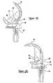
- FIG. 24is an elevational view of a tibial component including a bearing component according to an alternative embodiment of the present invention.
- FIG. 25is an elevational view of the component of FIG. 24 where the bearing component is rotated
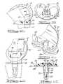
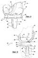
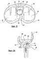
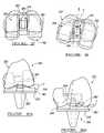
- FIG. 26is an exploded perspective view of a knee prosthetic according to an alternative embodiment of the present invention.
- FIG. 27is a partial section elevational view of the knee prosthetic of FIG. 26 in a neutral or zero degree rotation position
- FIG. 27 ais an front elevational view of the knee prosthetic of FIG. 26 with a predetermined amount of varus distraction
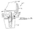
- FIG. 28is a partial cross-sectional elevational view of the knee prosthetic of FIG. 26 in a rotated position
- FIG. 28 ais a front elevational view of the knee prosthetic illustrated in FIG. 28 showing a limited amount of varus distraction
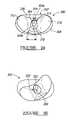
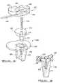
- FIG. 29is an exploded perspective view of a tibial component of a knee prosthetic according to an alternative embodiment
- FIG. 30is a front elevational view of the tibial component illustrated in FIG. 29 ;
- FIG. 31is top elevational view of a knee prosthetic illustrated in FIG. 29 where a superior portion is rotated relative to an inferior portion;
- FIG. 32is a front elevational view of the tibial component illustrated in FIG. 31 ;
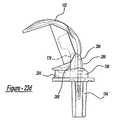
- FIG. 33is an exploded perspective view of a tibial component according to an alternative embodiment
- FIG. 34is a partial sectional view of the alternative embodiment illustrated in FIG. 33 ;
- FIG. 35is an exploded perspective view of a modular locked bearing tibial component according to an alternative embodiment
- FIG. 36is a cross-sectional view of the tibial component illustrated in FIG. 35 ;
- FIG. 37is an alternative embodiment of the modular locking bearing component illustrated in FIG. 36 ;
- FIG. 38is a diagrammatic elevational view of the locking bearing portion of the locking bearing tibial component
- FIG. 39is a cross-sectional view of alternative modular locking bearing components as illustrated in FIG. 36 ;
- FIG. 40is a cross-sectional view of a tibial component including a bearing component according to an alternative embodiment
- FIG. 41is a superior elevational view of the tibial and bearing components of FIG. 41 illustrating the bearing component in an installed position;
- FIG. 42is a perspective view of a femoral component according to an alternative embodiment.
- FIG. 43is a cross-sectional view of the femoral component taken along line 43 — 43 of FIG. 42 .
- the knee joint prosthesis 10is generally known as a posterior stabilized (PS) knee joint prosthesis 10 which is designed to provide adequate stability in case of moderate deterioration or instability of the human knee. This most typically occurs when the anterior and posterior cruciate ligaments are sacrificed or dysfunctional and the medial and lateral collateral ligaments remain functionally intact.
- PSposterior stabilized
- the knee joint prosthesis 10includes a femoral component 16 , a tibial component 18 and a floating tibial bearing 20 .
- the femoral component 16is adapted to be secured to a distal end of the femur 14 and includes a first condylar portion 22 and a second condylar portion 24 that provide a first femoral bearing surface 26 and a second femoral bearing surface 28 , respectively.
- the first and second condylar portions 22 and 24 of the femoral component 16are interconnected by an intercondylar portion 30 that defines an intercondylar recess 32 .
- the intercondylar portion 30includes a first lateral sidewall 34 and a second lateral sidewall 36 that are substantially planar and parallel to one another.
- the anterior portions of the first and second lateral sidewalls 34 and 36are connected by an anterior wall 38 and the posterior portions of the first and second lateral sidewalls 34 and 36 are connected by a posterior engagement member or elongated cam 40 .
- the intercondylar portion 30which includes the first and second lateral sidewalls 34 and 36 , the anterior wall 38 and the posterior engagement member 40 define the perimeter of a box 42 that defines the intercondylar recess 32 .
- the femoral component 16further includes an arcuate patellar portion 48 which is disposed on the anterior surface of the femoral component 16 .
- the patellar portion 48is shaped to allow anatomical tracking of a natural or prosthetic patella.
- the patella prostheses which are compatible with the present inventionmay be of varying shape, such as round or dome shaped and may be constructed from polyethylene, polyethylene with metal backing or other suitable materials.
- the femoral component 16 including the box 42is preferably formed as a unitary structure and preferably cast of a biocompatible high strength alloy, such as a cobalt-chromium-molybdenum alloy or other suitable material. All surfaces which do not contact the femur 14 are preferably highly polished to provide smooth articulating bearing surfaces.
- the tibial component 18is adapted to be secured to the proximal end of the tibial 12 after the tibia has been resected in a manner known in the art.
- the tibial component 18includes a substantially planar platform-like tibial tray 50 and an inferiorly extending tibial stem 52 .
- the tibial stem 52is adapted to be received in a corresponding opening made by the surgeon in the longitudinal center of the tibia 12 .
- the tibial tray 50 and the tibial stem 52define a conically shaped bore 54 axially extending through the tibial tray 50 and into the stem 52 .
- the tibial tray or plateau 50 and stem 52are preferably manufactured from cobalt-chromium-molybdenum or any other suitable biocompatible material.
- the top of the tibial tray 50is highly polished to provide a substantially smooth tibial bearing surface 56 .
- the floating or rotating bearing 20is located between the femoral component 16 and the tibial component 18 .
- the floating bearing 20has a substantially planar inferior bearing surface 58 which slidably moves relative to the highly polished tibial bearing surface 56 , further discussed herein.
- the floating bearing 20further includes a first superior articulating or bearing surface 59 and a second superior articulating or bearing surface 60 .
- the first bearing surface 59 and the second bearing surface 60articulate with the first bearing surface 26 of the condyle 22 and the second bearing surface 28 of the condyle 24 of the femoral component 16 .
- a substantially rectangular opening 62Positioned between the first and second bearing surfaces 59 and 60 is a substantially rectangular opening 62 that is slidably positioned about a center modular guide post 64 .
- the opening 62is defined by a substantially perpendicular peripheral sidewall 66 which is operable to engage the center guide post 64 .
- the floating bearing 20is preferably formed from a surgical grade, low friction, low wearing plastic, such as UHMWPE or other suitable material.
- the center guide post 64includes a substantially oval shaped outer peripheral sidewall 68 or any other appropriately shaped sidewall and a conically tapered sidewall 70 .
- the conically tapered sidewall 70is operable to be nestingly received within the conically tapered bore 54 to provide a friction fit that forms a Morse-type taper.
- the center guide post 64may be formed integral with the tibial component 18 .
- Extending axially through the center guide post 64is a substantially cylindrical bore 72 having a superiorly located counterbore 74 , as shown clearly in FIG. 5 a .
- the center guide post 64is formed from a combination of a cobalt-chromium-molybdenum portion 76 and a molded polymer portion 78 formed from UHMWPE or other suitable material.
- the polymer portion 78extends to the base of the tibial tray 50 to provide a polymer/polymer contact between the centering post 64 and the floating bearing 20 , via sidewalls 66 and 68 .
- Axially extending through the bore 72is a threaded bolt 80 which threadably engages a threaded bore 82 located inferiorly of the stem 52 .
- the bolt 80further includes a head 84 which is nestingly received within counterbore 74 .
- the head 84includes a hexagonal drive 86 that may be rotatably engaged by a hexagonal drive member.
- FIG. 5 ba second embodiment of a centering post 64 ′ is shown.
- the centering post 64 ′is substantially similar to the centering post 64 except that the metal portion 76 ′ extends above the tibial tray 50 , thereby providing a reduced or smaller polymer portion 78 ′.
- a polymer/metal contact or interfaceis formed between the floating bearing 20 and the centering post 64 ′, via the sidewalls 66 and 68 .
- each condyle 22 and 24 of the femoral component 16has a polycentric bearing surface 26 and 28 , respectively along the sagittal plane.
- each bearing surface 26 and 28is defined by a large anterior radius 80 and a smaller posterior/distal radius 82 .
- the large anterior radius 80is preferably about 1.497 inches and extends to about point 84 .
- the posterior/distal radius 82is about 0.945 inches and extends anterior the center line of the femoral component 16 up to point 84 .
- Point 84is located just anterior the floating bearing 20 .
- the bearing surface 59 and 60 of the floating bearing 20are formed with a single radius 86 along the sagittal plane having a radius of about 0.945 inches. Because the sagittal posterior/distal radius 82 of the femoral component 16 extends beyond the axial center line of the femoral component 16 anteriorly to point 84 , this radius congruently mates with the radius 86 of the floating bearing 20 from extension to full flexion. This mating provides a substantially fully mated and constant contact surface area between the femoral component 16 and the floating bearing 20 substantially through extension and flexion along the sagittal plane.
- Each bearing surface 26 and 28 of the condyles 22 and 24are arcuately shaped with a constant radius 88 of about 1.6 inches along the coronal plane.
- the bearing surfaces 59 and 60 of the floating bearing 20are likewise, formed from a constant radius 90 of about 1.6 inches along the coronal plane.
- Each of the radii 88 and 90congruently mate with one another to provide substantially full surface contact along the coronal plane from extension to flexion.
- This full surface contact along both the sagittal and coronal planessubstantially evenly disburses stresses between the femoral component 16 and the floating bearing 20 , as opposed to femoral components, which merely provide a smaller contact area, such as a line or point contact, either along the sagittal plane or the coronal plane which focuses stresses at these contact points, thereby potentially increasing wear in these areas.
- a contact area of greater than about 300 mm 2is maintained from extension to full flexion between the femoral component 16 and the floating bearing 20 .
- the floating bearing 20has an outer peripheral wall 92 which is substantially concentric with the outer peripheral wall 94 of the tibial tray 50 .
- the guide post 64is positioned just posteriorly the opening 62 defined by sidewall 66 . It should be noted that the post 64 is sized relative to the opening 62 such that the posterior stabilized knee joint prosthesis 10 provides anterior and posterior movement 96 , medial to lateral movement 98 , and rotation movement 100 of the floating bearing 20 relative to the tibial component 18 .
- the femoral component 16provides rotational movement along the sagittal plane relative to the floating bearing 20 , as well as varus and valgus movement relative to the floating bearing 20 .
- the posterior stabilized knee joint prosthesis 10may also simply provide the anterior to posterior movement 96 and the rotational movement 100 and eliminate the medial to lateral movement 98 of the floating bearing 20 relative to the tibial tray 50 .
- FIGS. 8 a – 8 epartial sagittal sectional views of the posterior stabilized (PS) knee joint prosthesis 10 illustrating the movement of the femoral component 16 and the floating bearing 20 relative to the tibial component 18 are shown from full extension in FIG. 8 a to full flexion in FIG. 8 e .
- the posterior stabilized (PS) knee joint prosthesis 10both anteriorly and posteriorly, is inherently stable at full extension when the patient is standing.
- the first and second femoral bearing surfaces 26 and 28are rested within the first and second tibial bearing surfaces 59 and 60 of the floating bearing 20 , respectively.
- the anterior surface 102 and the posterior surface 104 of the post 64do not engage the anterior portion 106 or the posterior portion 108 of the sidewall 66 .
- the posterior surface 104 of the post 64further does not engage the engagement member 40 of the femoral component 16 . If the knee joint prosthesis 10 would undergo a large hyper-extension or forward rollback (approximately 10 ⁇ ), the anterior surface 102 of the post 64 would engage the anterior portion 38 of box 42 in the femoral component 16 , while the floating bearing 20 would generally slide posteriorly relative to the tibial tray 50 . This engagement will further avoid posterior dislocation of the femoral component 16 relative to the tibial component 18 .
- the femoral component 16 with respect to the tibial component 18 and the floating bearing 20is generally most unrestricted between full extension, as illustrated in FIG. 8 a and the point of flexion where the posterior engagement member 40 and the posterior surface 104 of the post 64 initially engage, as illustrated in FIG. 8 b .
- This engagementgenerally occurs between about 20° to 45° of flexion.
- the femoral component 16is permitted to translate in the sagittal plane along with the floating bearing 20 relative to the tibial component 18 .
- the femoral component 16will remain substantially congruently positioned relative to the floating bearing 20 to provide a full articulating contact surface during this range of flexion.
- the femoral component 16 and the floating bearing 20are both able to move anteriorly and posteriorly relatively freely with respect to the tibial component 18 , via the bearing surfaces 56 and 58 between the floating bearing 20 and the tibial tray 50 .
- the exact amount of translation in the sagittal plane permitted by the knee joint prosthesis 10will of course, vary depending on the forces imparted by local soft tissues, muscles, tendons, ligaments, as well as forces transmitted from the tibia and fibula. These forces will, of course, vary from patient to patient, from activity to activity, as well as from implantation to implantation.
- the forced rollback provided by the engagement of the fixed modular post 64 with the engagement member 40enables a full surface contact area to be maintained between the femoral component 16 and the floating bearing 20 .
- This full surface contactis achieved because rollback is occurring between the floating bearing 20 and the tibial component 18 , via a sliding of the floating bearing 20 posteriorly atop the tibial tray 50 with surfaces 56 and 58 .
- Thisis in contrast to existing fixed bearing knee prostheses which achieve rollback, via the translation of the femoral component relative to a fixed bearing atop the tibial component.
- FIG. 9a top view of the tibial component 18 and the floating bearing 20 is shown with a fully constrained guide post 110 .
- the post 110is substantially similar to the post 64 , except that the outer peripheral wall 112 is oval with truncated ends 114 .
- the endwalls 114slidably engage the sidewalls 66 of opening 62 , thereby eliminating any lateral or medial movement 98 or rotational movement 100 with respect to the tibial component 18 .
- This fully constrained type kneetherefore, only allows anterior and posterior movement 96 of the floating bearing 20 relative to the tibial component 18 .
- the knee joint prosthesis 10may be converted from a posterior stabilized (PS) knee joint prosthesis 10 to a fully constrained knee joint prosthesis 10 ′.
- PSposterior stabilized
- Thisprovides for a fully constrained knee that maintains the large contact area (i.e. >300 mm 2 ), as well as having the desired rollback.
- the anterior motionmay be adjusted.
- removable sleevesmay be fashioned that slide on to post 64 to provide for further adjustment.
- This convertibilityenables a substantially convenient method for changing from a posterior stabilized (PS) to a fully constrained knee joint by simply replacing the guide post 64 , via the threaded bolt 80 .
- a closed box femoral component 16 ′may be used which includes a femoral stem 116 .
- the original femoral component 16would be replaced with the new femoral component 16 ′, while the tibial component 18 and the bearing component 20 would stay the same.
- the movement of the femoral component 16 , the tibial component 18 and bearing member 20 relative to one another along the sagittal planeis substantially similar to that shown in FIGS. 8 a – 8 e of the posterior stabilized (PS) knee joint prosthesis 10 .
- a primary knee joint prosthesis 120according to the teachings of a third preferred embodiment of the present invention is shown.
- the tibial component 18 and the floating bearing 20are substantially the same as used with the other preferred embodiments.
- the only differencesare with respect to the femoral component 122 and the central post 124 .
- the post 124is substantially similar to the post 64 except that the height of the post is reduced so that it does not extend above or out beyond the opening 62 .
- the femoral component 122includes the first and second condyles 22 and 24 having the first and second bearing surfaces 26 and 28 , respectively.
- the femoral component 122further includes the articulating patella portion 48 .
- the rollback of the floating bearing 20is achieved by the remaining soft tissues and ligaments of the patient.
- the floating bearing 20is initially centrally positioned about the tibial tray 50 similar to the other preferred embodiments during full extension. At about 25° to 45° of flexion, rollback of the floating bearing 20 starts and is substantially maintained through full flexion because of the cruciate ligament causing the floating bearing 20 to roll back.
- the primary knee joint prosthesis 120may be converted from a primary knee joint prosthesis 120 to a posterior stabilized (PS) knee joint prosthesis 10 or a fully constrained knee joint prosthesis 10 ′ by simply replacing the post 124 and the femoral component 122 without having to change the tibial component 18 or the tibial bearing 20 .
- PSposterior stabilized
- FIG. 13a partial sagittal sectional view of a posterior stabilized (PS) knee joint prosthesis 10 ′′ according to the teachings of a fourth preferred embodiment of the present invention is shown.
- PSposterior stabilized
- FIG. 13a partial sagittal sectional view of a posterior stabilized (PS) knee joint prosthesis 10 ′′ according to the teachings of a fourth preferred embodiment of the present invention is shown.
- the guide post 130is secured to the tibial component 18 in substantially the same manner as that shown with regard to the knee joint prosthesis 10 .
- the difference in the guide post 130is that it includes a first guide portion 134 and a second guide portion 136 .
- the first guide portion 134is defined by a substantially oval shaped sidewall 138 similar to that shown in FIG.
- the second guide portion 136is also formed by an oval sidewall 140 which is larger than the oval sidewall 138 .
- the first guide portion 134is preferably formed from a molded polymer, such as UHMWPE and the second guide portion 136 is preferably formed from a cobalt-chromium-molybdenum.
- various other combinations between the first guide portion 134 and the second guide portion 136can also be provided such as a complete polymer assembly, complete metallic assembly or any other combination.
- the second guide portion 136has a height which does not extend beyond the bearing 134 and is positioned within opening 142 such that the second guide portion 136 only engages and controls the movement of the floating bearing 132 relative to the tibial component 18 .
- the second guide portion 134extends into the box 42 of the femoral component 16 such that the second guide portion 134 is operable to be engaged by the cam member 40 to control the movement of the femoral component 16 relative to the bearing 132 .
- the two stage guide post 138individually controls the relative movement of the femoral component 16 and the bearing component 132 with the first guide portion 134 and the second guide portion 136 , respectively. This provides for increased adjustability in the relative articulating motion of the knee joint prosthesis 10 ′′ while further maintaining a substantially full and continuous contact area between the femoral component 16 and the floating bearing 132 from extension to full flexion.
- a posterior stabilized (PS) knee joint prosthesis 146according to the teachings of a fifth preferred embodiment of the present invention which is designed to provide adequate stability in case of moderate deterioration or instability of the human knee.
- the knee joint prosthesis 146is shown in FIG. 16 as being secured to a tibia 148 and a femur 150 of a surgically resected left knee joint, with the tibia 148 and the femur 150 shown in phantom, and with the understanding that a suitable right knee joint prosthesis can be similarly constructed.
- the knee joint prosthesis 146includes a femoral component 152 , a tibial component 154 and a floating tibial bearing 156 .
- the femoral component 152is adapted to be secured to the distal end of the femur 150 similar to the femoral component 16 , shown in FIG. 1 .
- the femoral component 152includes a first condylar portion 158 and a second condylar portion 160 that provides a first femoral bearing surface 162 and a second femoral bearing surface 164 , respectively (see FIG. 17 ).
- the first and second condylar portions 158 and 160are inter-connected by an inner condylar portion 166 that defines an inner condylar recess 168 .
- the inner condylar portion 166is defined by first and second lateral sidewalls 170 and 172 , anterior wall 174 , posterior engagement member or cam 176 and top 178 .
- the top 178may either be an open or closed top, depending upon the desired configuration.
- the femoral component 152also includes an arcuate patellar portion 180 which is disposed on the anterior surface of the femoral component 152 .
- the patellar portion 180is shaped to allow anatomical tracking of a natural or prosthetic patella.
- the patella prosthesiswhich are compatible with the present invention may be of varying shapes, such as round or dome shaped and may be constructed from polyethylene, polyethylene with metal backing or other suitable materials.
- the femoral component 152is preferably formed as a unitary structure and cast from a biocompatible high strength alloy, such as cobalt-chromium-molybdenum alloy or other suitable biocompatible material.
- the surfaces which do not contact the femur 150are preferably highly polished to provide smooth articulating bearing surfaces.
- the tibial component 154is substantially similar to the tibial component 18 and is likewise adapted to be secured to the proximal end of the tibial 148 after the tibia 148 has been resected in a manner known in the art.
- the tibial component 154includes a substantially planar plat form-like tibial tray 182 and an inferiorly extending tibial stem 184 .
- the tibial stem 184is adapted to be received in a corresponding opening made by a surgeon in the longitudinal center of the tibia 148 .
- the tibial stem 184is formed from a first planar member 186 , which is positioned substantially perpendicular to the tibial plateau 182 and a second planar member 188 which is positioned at a slight angle relative to the perpendicular axis of member 186 .
- Connecting member 186 with member 188is a tapered member 190 , which tapers at its distal end 192 to form a substantially I-beam cross-section.
- the tibial tray 182 and the tibial stem 184define a conically shaped bore 194 .
- the tibial tray 182 and the tibial stem 184are preferably manufactured from cobalt-chromium-molybdenum, or any other suitable material with the top of the tibial tray 182 being highly polished to provide a substantially smooth tibial bearing surface 196 .
- the floating bearing 156is positioned between the femoral component 152 and the tibial component 154 .
- the floating bearing 156includes a substantially planar inferior bearing surface 198 which slidably moves relative to the highly polished tibial bearing surface 196 .
- the floating bearing 156also includes a first superior articulating or bearing surface 200 and a second superior articulating or bearing surface 202 . Positioned between the first and second bearing surfaces 200 and 202 is an elongated opening 204 that is slidably positioned about a guide post 206 .
- the opening 204is defined by a pair of opposed lateral sidewalls 208 , a semi-circular or arcuate posterior sidewall 210 and an anterior sidewall 212 which has a pair of recessed lobes or ears 214 . Extending posteriorly from the opening 204 is a recessed area 216 positioned or located between the first bearing surface 200 and the second bearing surface 202 .
- the floating bearing 156is also preferably formed from a surgical grade, low friction, low wearing plastic, such as UHMWPE or other suitable material.
- the center guide post 206includes a substantially cylindrically shaped outer peripheral sidewall 218 and a conically tapered sidewall 220 .
- the conically tapered sidewall 220is operable to be nestingly received within the conically tapered bore 194 to provide a friction fit formed by a Morse-type taper.
- guide post 206may also be formed integral with the tibial component 154 .
- the guide post 206is constructed from a combination of a cobalt-chromium-molybdenum portion 222 and a molded polymer portion 224 formed from UHMWPE or other suitable material.
- the non-polymer portion 222extends up to the floating bearing 156 so that the floating bearing 156 contacts the cobalt-chromium-molybdenum cylindrical sidewall 218 .
- the polymer portion 224is molded to a post 226 and extends from above the floating bearing 156 into the recess 168 , also having the outer cylindrical sidewall 218 .
- the superior surface of the guide post 206has an anterior arcuate surface 228 and planar tapered superior sidewalls 230 .
- the anterior arcuate sidewall 228reduces or eliminates impingement of the post 206 within the inner condylar portion 166 during hyper-extension of the knee joint prosthesis 146 .
- the cylindrical sidewall 218also includes a posterior planar sidewall portion 231 , further discussed herein.
- Extending through the center guide post 206is a substantially cylindrical axial bore 232 having a stepped shoulder 234 .
- the stepped shoulder 234forms a retention mechanism to retain a threaded bolt 236 within the axial bore 232 .
- the non-polymer portion 222 of the guide post 206is machined and tooled in the configuration shown.
- the threaded bolt 236which includes a head 238 having a hexagonal drive 240 is then inserted into the bore 232 . Thereafter, the polymer portion 224 is molded over the elongated post 226 with the subsequent bore 232 being formed therein to create the shoulder 234 .
- the shoulder 234captures or retains the bolt 236 within the non-polymer portion 222 of the center guide post 206 . In this way, should the bolt 236 ever become loosened from threaded bore 242 , it will not be free to enter the articulating area of the knee joint prosthesis 146 .
- the tapered sidewall 220is matingly received within the tapered bore 194 and the bolt 236 is threadably engaged within bore 242 to securely hold the centering guide post 206 relative to the tibial component 154 .
- FIG. 21another embodiment of a centering post 244 is shown.
- the centering post 244is substantially similar to the centering post 206 , except that the non-polymer portion 222 of the cylindrical sidewall 218 includes a pair of arcuate lobes or ears 246 which extend anteriorly from the post 244 .
- the arcuate lobes 246extend anteriorly in the region of the floating bearing 146 and do not extend up beyond this region into the recess 168 of the femoral component 152 , thereby providing two guide portions or regions in the guide post 244 .
- the guide post 244also includes a posterior planar sidewall 248 extending throughout the length of the sidewall 218 .
- This planar sidewall region 248inhibits contact of the post 244 relative to the posterior sidewall 210 of the opening 204 formed within the bearing 156 .
- thisdisburses the force imparted by the post 244 to the thickest regions of the bearing 156 , thereby enhancing distribution of the engagement force between the post 244 and the bearing 156 .
- the guide post 244enables the bearing 156 to move anterior-posterior (A-P), as well as enables rotational movement of the bearing 156 relative to the tibial component 154 , similar to the guide post 206 .
- A-Panterior-posterior
- rotational movementis substantially limited to about +/ ⁇ 15°.
- the lateral sidewall 208 of the opening 204will engage one of the arcuate lobes 246 upon rotation of about 15°, thereby preventing further rotation of the bearing member 156 relative to the guide post 244 .
- Thisprovides a more constrained knee joint prosthesis 146 as compared to the guide post 206 . Therefore, by simply switching the guide post 206 with the guide post 244 , the rotational translation of the knee joint prosthesis 146 can be changed or constrained to about +/ ⁇ 15°, while still providing the same A-P translation.
- a guide post 244 ′is shown in use with the bearing 156 having a different shaped opening 250 .
- the opening 250includes an anterior sidewall 252 , a posterior sidewall 254 and a pair of angled lateral sidewalls 256 .
- the angled lateral sidewalls 256narrow the opening 250 posteriorly and widen the opening 250 anteriorly.
- the guide post 244 ′somewhat engages the posterior sidewall 254 with the arcuate lobes 246 substantially aligning with the angled lateral sidewalls 256 , such that there is little or no rotation of the bearing 156 relative to the post 244 ′ in extension.
- the bearing 156is forced posteriorly, further discussed herein, such that the guide post 244 ′ enters the widened recessed area between the lateral sidewalls 256 .
- the bearing 156is forced further posteriorly, further rotational freedom of movement is provided for the bearing 156 relative to the guide post 244 ′, as well as medial to lateral movement during this A-P translation, thereby providing a less constrained knee joint prosthesis 146 with increased flexion.
- This type of constraintclosely mimics an anatomical knee joint. Therefore, by simply changing the style bearing component or opening formed within the bearing 156 , varying constraint may be achieved.
- each condyle 158 and 160 of the femoral component 152has a polycentric bearing surface 162 and 164 , respectively along the sagittal plane.
- each bearing surface 162 and 164is defined by a large anterior radius 260 and a smaller posterior/distal radius 262 .
- Point 264is located just anterior the contact area of the floating bearing 156 .
- the bearing surfaces 200 and 202 of the floating bearing 156are formed with a single radius along the sagittal plane that corresponds to the posterior/distal radius 262 .
- the posterior radius 262 of the condyles 158 and 160extends up to point 264 cutting into a region of the condyles 158 and 160 to form a pair of opened anterior cavities or regions 268 .
- These opened cavities 268are positioned above the contact areas of the floating bearing 156 in extension and engage stop regions 270 of the floating bearing 156 during hyper-extension.
- the bearing 156further includes inner regions 272 which engage the inner regions 274 of the condyles 158 and 160 only during hyper-extension.
- the opened anterior cavities 268are positioned above the stops 270 to eliminate conformity in this region, thereby substantially reducing soft tissue impingement in this area.
- Contact between the stop region 270 and the anterior cavities 268only occur during hyper-extension of the knee joint prosthesis 146 .
- Each bearing surface 162 and 164 of the condyles 158 and 160are also arcuately shaped with a constant radius 276 , along the coronal plane.
- the bearing surfaces 200 and 202 of the floating bearing 156are likewise, formed from a similar constant radius 278 along the coronal plane of the floating bearing 156 .
- Each of the radii 276 and 278congruently mate with one another to provide a large surface contact area along the coronal plane which increases as flexion increases.
- FIGS. 20 a and 20 bthe contact area on the floating bearing 156 with the condyle bearing surfaces 162 and 164 in extension are shown shaded in FIG. 20 a .
- the floating bearing 156has an outer peripheral wall 280 which is substantially concentric with the outer peripheral wall 282 of the tibial tray 182 .
- the outer peripheral wall 280 of the floating bearing 156also includes a pair of posterior lip extensions 284 which extend out along the bearing surface 198 of the floating bearing 156 (see FIG. 18 ). This pair of lip extensions 284 eliminates undesirable moment arms as the femoral component 152 moves posterior and rolls up the posterior portion of the center guide post 206 during extreme flexion (see FIG. 23 d ).
- the floating bearing 156is substantially inhibited from tilting superiorly based upon the moment arms generated upon such flexion.
- the guide post 206is positioned substantially posteriorly of the opening 204 , such that the posterior stabilized knee joint prosthesis 146 provides anterior and posterior movement and rotational movement of the floating bearing 156 relative to the tibial component 154 . Also the femoral component 152 provides rotational movement along the sagittal plane relative to the floating bearing 156 , as well as varus and valgus movement relative to the floating bearing surface 156 . It should further be noted that by simply changing the post configuration or the opening configuration, various types of constraints may be easily accommodated.
- FIGS. 23 a – 23 dpartial sagittal sectional views of the posterior stabilized (PS) knee joint prosthesis 146 illustrating the movement of the femoral component 152 and the floating bearing 156 relative to the tibial component 154 are shown from extension in FIG. 23 a to flexion of 110° in FIG. 23 d .
- the posterior stabilized (PS) knee joint prosthesis 146both anteriorly and posteriorly, is inherently stable at full extension when the patient is standing.
- the first and second femoral bearing surfaces 162 and 164are nested within the first and second tibial bearing surfaces 200 and 202 of the floating bearing 156 , respectively.
- the stop portions 270are not in contact with the anterior cavities 268 in the femoral component 152 to inhibit soft tissue impingement in this region during extension.
- the anterior surface 286 and the posterior surface 288 of the guide post 206is generally not in engagement with the anterior sidewall 212 or the posterior sidewall 210 of the opening 204 or with the posterior cam 176 or the anterior wall 174 of the inner condylar portion 166 .
- the anterior surface 286 of the guide post 206would engage the anterior sidewall 174 of the inner condylar portion 166 .
- the pair of anterior cavities 268 of the femoral component 152would also engage the stops 270 of the bearing 156 , while the inner condylar bearing surfaces 274 would engage the inner surfaces 272 of the floating bearing 156 . This engagement will avoid posterior dislocation of the femoral component 152 relative to the tibial component 154 .
- the posterior cam 176will generally engage the posterior side 288 of the post 206 at about 40° of flexion, as shown in FIG. 23 b .
- the femoral component 152 , the tibial component 154 and the floating bearing 156is generally most unrestricted, such that the femoral component 152 is permitted to translate in the sagittal plane along with the floating bearing 156 relative to the tibial component 154 .
- the floating bearing 156rolls back posteriorly relative to the tibial tray 182 .
- a forced rollback of the floating bearing 156 relative to the tibial tray 182continues to occur while the contact area between the femoral component and floating bearing increases as shown in FIG. 20 b .
- the femoral component 156moves posteriorly and rolls up upon the posterior side 288 of the guide post 206 reducing the contact area between the femoral component 152 and the bearing 156 .
- the posterior lip extension 284prevent the floating bearing 156 from flipping up or tipping superiorly during this phase of flexion by reducing the moment arm about the contact point of the posterior cam 176 to the contact surface between the femoral component 152 and the floating bearing 156 .
- forced rollbackprovided by the engagement of the fixed modular guide post 206 with the cam 176 provides a surface contact area between the femoral component 152 and the floating bearing 156 which increases as flexion increases (see FIGS. 20 a – 20 b ), until extreme flexion (i.e., ⁇ 110°).
- extreme flexioni.e., ⁇ 110°.
- wear on the guide post 206is substantially reduced because the post/cam contact occurs after the loading phase of normal gait.
- the cam 176contacts the guide post 206 closer to the tibial/femoral articulation or lower along the guide post 206 .
- This lower contact pointreduces the moment arm on the guide post 206 , and therefore, the stresses on the guide post 206 .
- the guide post 206maintains the position of the bearing 156 from 0° to 40° of flexion since tibial or femoral congruency is maintained and the bearing cannot slide forward with the posterior surface of the opening, engaging the posterior side 288 of the post 206 .
- a tibial component 300which may be used in place of the tibia component described above in conjunction with a posterior stabilized (PS) knee joint prosthesis, which is used to provide adequate stability in case of moderate deterioration instability of the human knee, as described above.
- PSposterior stabilized
- the tibial component 300includes a tibial tray 302 .
- a posterior stabilizing post (PS post) or guide post 304extends superiorly from the tibial tray 302 .
- the guidepost 304may be either formed integrally with the tibial tray 302 , or may be modular and affixed to the tibial component 300 similar to that illustrated in FIG. 15 above.
- the PS post 304includes a generally tear drop or pear shape cross-section, such that a posterior portion 304 a of the PS post 304 has a longer or larger arc length than an anterior portion 304 b of the PS post 304 .
- a bearing component 306is disposed superiorly of the tibial tray 302 .
- the superior side of the tibial tray 302defines a tibial tray bearing surface 308 .
- An inferior side of the bearing component 306may articulate with the tibial tray bearing surface 308 .
- a superior side of the bearing component 306defines femoral bearings including a first condylar bearing surface 310 and a second condylar bearing surface 312 . It is understood the tibial component 300 may be placed in either the right or left knee of a patient.
- the bearing component 306also defines a bearing hole or bore 314 .
- the bearing hole 314includes at least a posterior wall or section 316 and an anterior wall or section 318 .
- the posterior wall 316includes a smaller arc length than that of the anterior wall 318 .
- the bearing hole 314has an area or perimeter greater than the perimeter of the PS post 304 . Therefore, the bearing member 306 is free to slide or articulate on the tibial tray bearing surface 308 when implanted in a knee. Nevertheless, the motion of the bearing component 306 is restricted by the presence of the PS post 304 . In particular, the bearing component 306 is able to move anterior and posterior, medial/lateral, and rotate around the PS post 304 .
- the inclusion of the bearing hole 314allows for at least three degrees of freedom of the bearing component 306 while the PS post 304 limits the range of motion within each degree.
- the bearing component 306is moved to its most anterior position and rotated to its maximum laterally rotated position.
- a medial wall 320 of the bearing hole 314engages a medial side 322 of the PS post 304 .
- a posterior wall 324 of the bearing hole 314engages a posterior side 326 of the PS post 304 .
- the shapes of the PS post 304 and the bearing hole 314determine the amount of articulation allowed of the bearing component 306 . Therefore, increasing the anterior to posterior length of the PS post 304 reduces the amount of anterior and posterior movement of the bearing 306 component. Decreasing anterior to posterior length of the post 304 increases the amount of anterior and posterior articulation of the bearing component 306 .
- both the tear drop shaped bearing hole 314 and the PS post 304 having the inverse tear drop shapeprovides a controlled and constrained movement of the bearing component 306 , while still allowing for the various degrees of freedom.
- the complementary shapes of the bearing hole 314 and the PS post 304limit the amount of rotation of the bearing component 306 .
- the relative size of the bearing hole 314 and the PS postdetermine the limitation of rotation. In other words, as the bearing component 306 moves posterior, rotational movement of the bearing component 306 relative to the tibial tray 302 is limited.
- the PS knee 350includes the general advantages of the preceding embodiments wherein the PS knee prosthesis 350 allows for a general stabilization of a weakened natural knee.
- the PS knee prosthesis 350generally includes a femoral component 352 , a bearing component 354 and a tibial component 356 .
- the femoral component 352includes a first condylar portion 358 and a second condylar portion 360 . It is understood that the PS knee prosthesis 350 may also be implanted into either a left knee or a right.
- the femoral component 352also includes a patellar groove 362 , which allows for a generally natural articulation of a patella or patellar implant.
- a box 364is provided between the first condylar portion 358 and the second condylar portion 360 . The box 364 substantially closes the central portion of the femoral component 352 and provides a cam surface for a posterior stabilizing (PS) post 366 described more fully herein.
- PSposterior stabilizing
- the bearing component 354includes a femoral bearing superior side 368 , which includes a first superior articulating or bearing surface 370 and a second superior articulating or bearing surface 372 .
- a femoral bearing superior side 368defined by the bearing component 354 , and positioned between the first bearing surface 370 and the second bearing surface 372 , is an elongated opening 374 adapted such that the PS post 366 may extend through the bearing opening 374 .
- the tibial component 356includes a substantially planar platform or tibial tray 376 and an inferiorly extending tibial stem 378 .
- the tibial stem 378is formed substantially similar to the tibial stem 184 described in relation to the fourth embodiment of the present invention.
- the anterior surface of the tibial tray 376is a tibial tray bearing surface 380 .
- the tibial component 356may generally be made of titanium, cobalt chromium alloys, or other suitable biologically compatible metallic alloys.
- the tibial tray bearing surface 380is generally highly polished to allow for a smooth articulation between the tibial tray bearing surface 380 and the bearing component 354 .
- the PS post 366Extending superiorly from the tibial articulating surface 380 is the PS post 366 .
- the PS post 366illustrated here, is formed integrally with the tibial tray 376 , it will be understood that the PS post 366 may be modular and affixed to the tibial component 356 with an appropriate means, such as that disclosed above.
- the PS post 366generally includes an inferior portion 382 , and a superior portion 384 .
- the inferior portion 382has a cross-section, that allows the bearing component 354 to articulate, and rotate on the tibial tray bearing surface 380 .
- the superior portion 384is pyramidal or oval-conical in shape.
- the superior portion 384includes an anterior posterior (or sagittal plane) length that is greater than a medial to lateral (or coronal plane) width of the superior portion 384 .
- anterior posterior (or sagittal plane) lengththat is greater than a medial to lateral (or coronal plane) width of the superior portion 384 .
- This shapeis exemplary, other shapes such as ovals tapering to the inferior portion 382 may also be used.
- the superior portion 384is tapered along the sagittal plane towards a superior end, such that the superior end is smaller than the inferior end. The taper allows the femoral component to distract varus and valgus, as discussed further herein, when it is in a substantially non-rotated or non-engaged position. Nevertheless, when it is rotated the superior portion 384 of the PS post 366 limits the varus or valgus distraction of the femoral component 352 . This is done by contacting or engaging a portion of the side walls of the intercondylar box 3
- the anterior to posterior dimension of the superior portion 384is equal to or greater than the medial to lateral width of the box 364 .
- the medial to lateral width of the superior portion 384is less than the medial to lateral width of the box 364 .
- the femoral component 352may rotate relative the tibial component 356 .
- thisdefines a substantially undistracted position of the knee, where the femoral component 352 may rotate with substantial freedom.
- the femoral component is 352is not rotated it may also have relatively large amounts of varus and valgus distraction.
- the femoral component 352may include varus and valgus distraction, such that while one of the condylar portions 358 or 360 remain in substantial contact with its respective bearing surface 370 or 372 , the other rides up along the bearing surface.
- the femoral component 352is able to tilt relative to the tibial tray 376 .
- the femoral component 352when the femoral component 352 is not rotated relative the tibial component 356 , that is, the anterior/posterior axis A of the femoral component 352 is substantially parallel to the anterior/posterior axis B of the PS post 366 , substantially no portion of the superior portion 384 of the PS post 366 is touching or engaging a portion of the box 364 .
- the femoral componentmay substantially include various varus or valgus distraction X, generally only limited by the soft tissue to between about 0° and about 20°, relative to the tibial component 356 . As illustrated in FIG.
- the femoral component 352when the femoral component 352 is not rotated, that is rotated approximately 0°, the femoral component 352 can distract relative the tibial component 356 . Generally, the femoral component 352 can distract at least about 20° when in this unrotated position. It will be understood, however, that different designs of the superior portion 384 of the PS post 366 can limit or increase the amount of distraction allowed the femoral component 352 . Moreover, when the post 366 is modular, different PS posts may have different sizes or shapes to allow more or less distraction of differing degrees of rotation.
- the superior portion 384 of the PS post 366engages the box 364 .
- the superior portion 384 of the PS post 366is shaped so that the superior portion 384 of the PS post 366 engages the box 364 at a predetermined rotational degree.
- the amount of varus or valgus distractionis substantially limited or eliminated. Therefore, when the femoral component 352 is rotated relative the tibial component 356 , the femoral component 352 is more stabilized in the varus or valgus distraction positions.
- Varus and valgus distraction of the femoral component 352can be limited or eliminated depending upon the amount of rotation of the femoral component 352 relative the tibial component 356 .
- the varus and valgus distraction Y of the femoral component 352is substantially limited.
- the varus and valgus distractionis only about between 0° and about 5°.
- the varus and valgus distractionmay also be substantially eliminated when the femoral component 352 is rotated far enough.
- the rotational positiondetermines or limits the distraction depending upon the knees implanted in the particular patient. It will be understood that varying the size of the superior portion 384 of the PS post 366 varies the amount of rotation required to limit varus or valgus distraction.
- a generally pyramidal or conical shape of the superior portion 384is illustrated other appropriate shapes may be used. Other shapes include tapering rectangles or triangular pyramids.
- the PS guide post 206shown above in FIG. 15 and described, may also provide an appropriate shape. The shapes, at one rotational displacement, allows the femoral component 352 to distract varus or valgus from the tibial component 356 , while at another rotational displacement, the femoral component 352 is not able to distract or distracts to a lesser extent.
- the PS knee prosthesisgenerally includes a tibial component 400 and a bearing member or component 402 .
- the tibial component 400includes a tibial bearing component 404 , which operatively interconnects with a tibial connector 406 .
- the tibial connector 406includes a tibial stem 408 , a tibial connecting component tray 410 , and a tibial connecting component bore 412 , which extends through the tibial stem 408 and through the tibial connecting component tray 410 .
- a superior surface 413 of the tibial connecting tray 410defines a generally bi-helical surface, which includes a raised middle portion 414 , a first depression 416 , and a second depression 418 , wherein the depressions are formed on either side of the raised portion 414 .
- the tibial bearing component 404includes a supplementary tibial stem 420 , that extends inferiorly from a tibial bearing component tray 422 .
- the tibial bearing component stem 420forms a generally taper connection with the bore 412 of the tibial connecting member 406 . Although the connection is taper in design, the supplementary tibial stem 420 is able to rotate and distract within the bore 412 .
- Extending superiorly from the tibial bearing member tray 422is a post 426 .
- An inferior side 425 of the tibial bearing member tray 422defines a surface, which substantially mates with the superior surface 413 of the tibial connecting member 406 .
- a superior depression 428extends the anterior to posterior length of the tibial bearing member tray 422 , although obstructed by the post 420 .
- On a first side of the superior compression 428is a first lobe 430 , which extends inferiorly from the tray 422 and on a second side, a second lobe 432 , which also extends inferiorly from the tray 422 . Therefore, the inferior surface 425 of the tray 422 substantially mates or nests with the superior surface 413 of the tibial connecting member 406 .
- the tray 422also defines a bearing articulation surface 434 on its superior side.
- the articulating surface 434is substantially polished, such that the bearing component 402 may articulate smoothly on the surface 434 .
- the post 426includes an inferior portion 436 substantially closer to the articulating surface 434 than a superior portion 438 of the post 426 .
- the inferior portion 436is illustrated to have a substantially square outer perimeter. As described more fully herein, however, the perimeter of the inferior portion 436 may have any appropriate perimeter, such that it can, in at least one orientation, lock with the bearing component 402 .
- the superior portion 438 of the post 426is adapted to substantially mate with a cam formed in an appropriate femoral component (not illustrated here), an such as described above.
- the bearing component 402generally includes a first bearing portion 440 and a second bearing portion 442 , which would substantially mate with an appropriate femoral component, described above, but not illustrated here. Formed between the first and second bearing portions 440 , 442 is a bearing opening 444 . The bearing opening 444 extends through the bearing component 402 allowing for the post 426 to extend through the bearing opening 444 . An inferior surface of the bearing component 402 defines a tibial bearing surface 446 . The tibial bearing surface 446 of the bearing component 402 is able to articulate on the surface 434 of the tibial bearing component 404 .
- the opening 444has a dimension in at least one direction, which substantially mates with the inferior portion 436 of the post 426 .
- the inferior portion 436is substantially square in perimeter and the opening 444 has a medial lateral distance, which is substantially equal to the length of a side of the inferior portion 436 . Therefore, when the bearing component 402 is resting on the surface 434 , the bearing component 402 may not substantially move medially or laterally relative to the tibial bearing component 404 . Nevertheless, the anterior to posterior length of the opening 444 is greater than the length of the anterior posterior side of the inferior portion 436 of the post 426 . The greater dimension allows the bearing component 402 , while resting on the surface 434 , to move anteriorly and posteriorly.
- bearing opening 444having a medial to lateral width substantially equal to the medial to lateral width of the posterior component 436 is that the bearing component 402 may not twist or rotate relative the tibial bearing component 404 . Therefore, the bearing component 402 only has one degree of freedom, that being anteriorly and posteriorly, relative the tibial bearing component 404 .
- the bearing component 402does not rotate relative the tibial bearing component 404
- the tibial bearing component 404is able to rotate relative the tibial connecting portion 406 .
- the bearing component 402 and the tibial bearing component 404rotate substantially as one member.
- the inferior surface 425 of the tray 422rides along the superior surface 413 of the tibial connecting portion 406 .
- the rotationcauses a distraction of the tibial bearing component 404 from the tibial connecting component 406 .
- the amount of distractiondepends upon the size of the first or second lobes 430 or 432 or the raised ridge 414 . The greater the size, the greater the distraction.
- the soft tissuesuch as the medial and lateral collateral ligaments which remain in the knee after the knee replacement, tightens.
- Thisallows for the knee to remain stable even when the portions are rotating relative one another.
- Thisallows a knee prosthesis, including the tibial component 400 and the bearing component 402 , to include less constraints to support the knee in these inferior portion 436 of the post 426 in only one direction, the bearing component 402 may still articulate anteriorly and posteriorly on the surface 434 .
- the tibial bearing component 404is formed of a substantially rigid or hard material, such as cobalt chromium alloys, or titanium, or other appropriate biologically compatible metals. While the tibial connecting component 406 and the bearing component 402 are formed of a suitable, more flexible material, such as ultra high molecular weight polyethylene.
- the tibial connecting component 406including the bore 412 , is reinforced by the supplementary tibial post 420 of the tibial bearing component 404 . Therefore, although the tibial connecting component 406 is formed of a polyethylene material, the supplementary tibial post 420 , formed of an appropriate rigid material, reinforces the tibial post 408 .
- the bearing component 402may move anteriorly and posteriorly relative to the tibial bearing component 404 .
- rollbackmay be achieved.
- thisallows congruent rollback and contact between the femoral component and the bearing component. Therefore, not only is rollback achieved, but a continuous and congruent contact is allowed by the inclusion of a distinct tibial bearing component 404 .
- the soft tissueis tightened, due to the distraction of the tibial bearing component 404 from the tibial connecting component 406 , the knee, into which the portions are implanted, produces rollback. This again reduces the need for other constraints otherwise necessary to be formed into the knee prosthesis when not using the tibial component 400 and the bearing component 402 .
- a ninth embodiment of a tibial component 470 and an associated bearing component 472is illustrated for a knee prosthesis of the present invention.
- a cruciate retaining tibial component 470 and bearing component 472are illustrated, it will be understood that the following embodiment may also be used with a posterior stabilized knee prosthesis or other appropriate knee requiring a bearing component as disclosed herein, that may articulate with a tibial component.
- a postmay be included on the tibial component 470 where the post is either modular or formed integrally with the tibial component 470 .
- An openingmay then be formed in the bearing component 472 to allow a floating bearing with a PS post.
- the tibial component 470generally includes a tibial stem 474 and a tibial tray 476 .
- the superior side of the tibial tray 476defines a tibial tray bearing surface 478 .
- the tibial component 470is generally formed of an appropriate biocompatible metal, such as cobalt chromium alloys or titanium. Therefore, the articulating surface 478 may be substantially highly polished to allow for a smooth articulation of the bearing component 472 .
- the bearing component 472generally includes a first condylar bearing portion 480 and a second condylar bearing portion 482 .
- the first and second condylar bearing portions 480 and 482generally bear the condylar portions of the femoral component or of a natural femur.
- the bearing component 472also includes a superior portion 482 , which is formed of an appropriate bearing material. Bearing material examples may include polyethylene or other appropriate bearing materials.
- the superior portion 482is molded to a hard posterior portion or base 484 .
- the base 484may be formed of appropriate hard material, for example, cobalt chromium alloys, ceramic, etc.
- the exterior surface of the base 484may be augmented with other materials to increase the hardness of the exterior surface.
- the exterior surfacemay be oxidized to form a hard ceramic thereon or may include a diamond coating to increase the hardness of the exterior surface of the base 484 .
- the base 484may be untreated or unaugmented.
- the base 484includes the superior portion 482 molded thereto.
- a flange 486may be included on the base 484 .
- the flange 486may extend around the entire perimeter of the base 484 and spaced a distance from the exterior perimeter. Therefore, the material of the superior portion 482 may be molded over the flange 486 and extended to the external perimeter of the base 484 .
- the flange 486allows the material of the superior portion 482 to be substantially held or locked onto the base component 484 . This assists during stresses after implantation into a body when the bearing component 472 articulates on the tibial articulation surface 478 .
- the flange 486stabilizes the superior portion 482 relative the base 484 .
- a non-continuous flangemay be used such as tabs or blocks formed on the superior side of the base 484 or roughened surfaces, ridges, grooves, etc.
- the inferior surface 488 of the base 484may also be highly polished to increase ease of articulation between the inferior surface 488 and the tibial tray bearing surface 478 .
- Thisallows a metal-on-metal bearing surface between the bearing component 472 and the tibial component 470 while enabling polyethylene articulation with the femoral component.
- metal-on-metalis particularly illustrated here, it will be understood that other appropriate articulating surfaces may be included.
- the superior portion 482including a polyethylene, can be molded onto an appropriate ceramic, which may form the base 484 . The ceramic may be hardened to articulate with the tibial articulating surface 478 .
- a tenth embodiment of a tibial component 500 and a bearing member 502 of a convertible knee prosthesisare illustrated for use with the present invention.
- the bearing component 502may be locked or fixed relative to the tibial component 500 according to this embodiment, with a locking component 510 .
- the tibial component 500may be substantially similar to the modular tibial components illustrated and discussed above as shown in FIG. 15 . In this way, the tibial component 500 may be used with a plurality of embodiments as discussed herein, and may also be used in the present embodiment to form a locked or fixed bearing knee prosthetic.
- the bearing component 502may include a post formed integrally therewith to form a PS knee with a fixed bearing.
- a cruciate retaining kneemay be formed when the locking component 510 includes a post which extends above the bearing component 502 .
- the tibial component 500includes a tibial stem 504 , which extends inferiorly from a tibial tray 506 .
- a tibial bore 508is adapted to receive the locking component 510 , which includes a post 512 , that is adapted to be received in the bore 508 , via a Morse taper connection.
- a screw or other member 514may be placed through the locking member 510 to engage an internal thread 516 in the tibial stem 504 .
- the locking member 510is oblong and includes a first locking portion or slot 518 and a second locking portion or edge 520 .
- the bearing component 502on a superior side, includes a first and second condylar bearing portion 522 and 524 .
- the bearing component 502may be formed of any appropriate material, the bearing component 502 is generally formed of an ultra high molecular weight polyethylene.
- the bearing component 502also defines a locking recess 526 .
- the locking recess 526generally mates with the locking member 510 . It will be understood that although a particular embodiment is illustrated here, other appropriate shapes may be formed, in the bearing component 502 , such that the locking recess 526 will mate with an appropriately formed locking member 510 .
- the locking recess 526includes a mating lip or ledge 528 , which engages or mates with the locking ledge 520 on the locking component 510 .
- the material of the bearing component 502is generally slightly flexible, such that it may be deformed under enough stress.
- the locking lip 528may be engaged under the locking ledge 520 and the bearing component 502 may then snap or be flexed to engage the locking member 510 .
- the superior portion of the locking member 510is substantially received in the locking recess 526 of the bearing component 502 .
- a locking bar 530engages a locking bore 532 , formed in the bearing component 502 , and the locking slot 518 of the locking member 510 . Therefore, the locking bar 530 interlocks the locking member 510 and the bearing component 502 . Once the locking bar 530 is, transversely inserted, the bearing component 502 is held relative the tibial component 500 .
- the tibial component 500may be used for floating bearing knee prosthesis where the post extending from the tibial component is modular and is secured within bore 508 .
- the same tibial component 500may be used and once the implant procedure has begun, the physician may determine that a floating bearing posterior stabilized knee is not needed, however, a PS knee prosthesis with a fixed bearing is desired.
- Thisalso allows revision of a previously implanted knee prosthesis from a floating bearing to a fixed bearing without replacing a well fixed tibial component. Rather than providing a entirely separate fixed bearing component, this embodiment will allow a locking member 510 and an appropriate bearing component 502 to form a fixed bearing knee prosthesis.
- a locking component 550is held into the tibial component 500 with a Morse Taper and the screw 514 .
- the locking component 550includes an anterior locking portion 552 and a posterior locking portion 554 .
- the anterior locking portion 552includes a slot 556
- the posterior locking portion 554includes an anteriorally extending finger 558 .
- the slot 556 on the anterior locking portion 552receives the locking bar 530 after the bearing component 540 has been seated in place.
- the bearing component 540includes a posterior cut out or recess 560 to receive the posterior locking portion 554 .
- the bearing component 540also includes an anterior cut out or recess 562 to receive the anterior locking portion of 552 .
- the bearing component 540includes an anterior to posterior recess or channel 564 to receive the superior extending portion of the locking component 550 . Therefore, the bearing 540 includes several recesses or cut outs formed into the bearing such that it will fit properly onto the tibial tray 506 .
- the bearing component 540includes a posterior portion 566 which extends onto the tibial tray 506 posteriorly of the posterior locking member 554 .
- the locking member 572includes an anterior locking portion 574 which includes a slot 576 to receive the locking bar 530 . Also formed on the locking component 572 is a posterior locking portion 578 which includes an anteriorly extending finger 580 .
- the locking component 572also includes an anteriorally extending tray portion 582 which may include an inferiorly extending finger 584 . Also included on the tray portion of the locking component 572 is a posteriorly extending tray portion 586 which also includes an inferiorly extending finger 588 . Therefore, the locking component 572 includes an upper or tray portion 590 which substantially surrounds the tibial tray 506 to provide further support, strength and rigidity.
- the tray portion 590may provide any appropriate thickness necessary to provide a required strength to the locking component 572 .
- the bearing component 592does not require any additional cut outs to accommodate the upper portion of the locking component 572 .
- the anterior to posterior recess of the embodiment illustrated in FIG. 38is not required. Therefore, the bearing component 592 , used in conjunction with the locking component 572 , may be similar to other fixed bearings. This may assist in component choice and relieving inventory constraints by not requiring an additional and new bearing component.
- an eleventh embodiment of a knee prostheticmay include a tibial component 600 and a bearing member or component 602 .
- the tibial component 600generally includes a tibial stem 604 and a tibial tray 606 which includes a tibial tray bearing surface 608 .
- the tibial tray bearing surface 608is where the bearing component 602 bears upon the tibial tray 606 and may articulate thereon.
- the tibial component 600may also include a posterior (PS) stabilizing or cruciate retaining (CR) guide post 610 extending superiorly from the tibial tray bearing surface 608 .
- the post 610includes a superior or locking portion 612 and an inferior or cutout portion 614 .
- the superior portion 612 of the post 610includes a medial to lateral (M-L) dimension that is greater than its anterior to posterior (A-P) dimension.
- M-Lmedial to lateral
- A-Panterior to posterior
- the inferior portion 614also includes an M-L dimension which is greater than its A-P dimension, but is also smaller in each of those dimensions than the respective dimensions of the superior portion 612 . Therefore, the inferior portion 614 defines a cutout or recess which the superior portion 612 overhangs.
- the bearing component 602includes the portions generally described above included in the bearing components, these generally include a bearing opening or hole 616 .
- the bearing hole 616defined by the bearing component 604 , includes an A-P dimension which is greater than its M-L dimension. Therefore, the bearing opening 616 , defined by the bearing component 602 , includes a substantially oblong or oval shape aligned in the A-P direction.
- the bearing component 602also includes a first condylar bearing surface 618 and a second condylar bearing surface 620 .
- the superior portion 612will not impinge upon or extend over the first and second condylar bearing surfaces 618 and 620 . Because the superior portion 612 overhangs a portion of the bearing component 602 , the bearing component is held substantially adjacent the tibial bearing surface 608 . Nevertheless, the bearing component 602 may rotate and articulate in an anterior to posterior direction and in a medial to lateral direction because of the bearing opening 616 is greater in all dimensions than the inferior portion 614 of the post 610 . The superior portion 612 of the post 610 ensure that the bearing component 602 will not substantially leave its articulating position on the tibial tray bearing surface 608 during use. Substantially prevent rocking or tipping of the bearing relative to the tibial plate 606 .
- the bearing component 604may be implanted over the superior portion 612 of the post 610 by rotating the bearing component 602 such that the A-P dimensions of the bearing hole 616 match with the angled M-L dimension of the superior portion 612 and the M-L dimensions of the bearing hole 616 match with the angled A-P dimensions of the superior portion 612 , or that the bearing hole 616 is greater than each of the dimensions of the superior portion 612 , such that the bearing component 604 may fit over the superior portion 612 of the post 610 .
- the bearing component 602may be rotated to its operational orientation. In the operational orientation, the dimensions of the bearing hole 616 interfere with the dimensions of the superior portion 612 such that the bearing component 604 is held substantially adjacent the tibial bearing surface 608 .
- the bearing hole 616is substantially keyed to the superior portion 612 of the post 610 . It will be understood that although an oval shape is illustrated here offset relative to the A-P axis, other appropriate shapes and axes may be used to form the keyed relationship. Where a first or non-operative position of the bearing component 602 , relative the tibial component 600 allows for removal of the bearing component 602 , relative the tibial component 600 , but an operative orientation of the bearing component 602 relative the tibial component 600 does not allow the bearing component 602 to substantially distract from the tibial tray bearing surface 608 .
- inferior portion 614 of the post 610may have a height which is greater than the height of the bearing component 602 to allow distraction in a superior direction relative the tibial tray bearing surface 608 , yet still engage the superior portion 612 of the post 610 before dislocating from the post 610 .
- the femoral component 650generally includes a first condylar portion 652 and a second condylar portion 654 each defining a condylar bearing surface that may articulate with an appropriate bearing component, as described above. Positioned between the first and second condylar portions 652 and 654 is an inter-condylar box 656 .
- the inter-condylar box 656includes a first sidewall 658 and a second sidewall 660 . Interconnecting the two sidewalls 658 and 660 is a top wall or arch 662 .
- the top wall 662includes a radius of curvature such that it is not substantially planar or flat across its width.
- the edge or interconnection between the first wall 658 and the top 662includes a radius, as does the interconnection between the second wall 660 and the top 662 . Therefore, the superior portion of the box 662 is substantially defined by a radius which has a center of curvature inferior of the top 662 of the box 656 .
- a femuris prepared to accept the femoral component 650 by first removing the distal end of the femur and then reaming and chiseling a portion of the femur to accept the box 656 .
- the top 662 of the box 656includes a radius
- the chiseling and reamingis substantially reduced and lessened when compared to the preparation necessary for a box that is substantially square or has sharper angles at the corners of the box. Therefore, the box 656 with the radius top 662 can decrease the amount of surgical time required to prepare the femur for implantation of the femoral component 650 . In addition, it reduces the amount of bone that must be removed to accept the femoral component 650 .
- the interior of the box 656still provides a cam portion to accept a PS post which extends from an appropriate tibial component.
Landscapes
- Health & Medical Sciences (AREA)
- Orthopedic Medicine & Surgery (AREA)
- Physical Education & Sports Medicine (AREA)
- Cardiology (AREA)
- Oral & Maxillofacial Surgery (AREA)
- Transplantation (AREA)
- Engineering & Computer Science (AREA)
- Biomedical Technology (AREA)
- Heart & Thoracic Surgery (AREA)
- Vascular Medicine (AREA)
- Life Sciences & Earth Sciences (AREA)
- Animal Behavior & Ethology (AREA)
- General Health & Medical Sciences (AREA)
- Public Health (AREA)
- Veterinary Medicine (AREA)
- Prostheses (AREA)
Abstract
Description
Claims (14)
Priority Applications (3)
| Application Number | Priority Date | Filing Date | Title |
|---|---|---|---|
| US10/188,305US6972039B2 (en) | 1999-03-01 | 2002-07-01 | Floating bearing knee joint prosthesis with a fixed tibial post |
| AT03254203TATE527967T1 (en) | 2002-07-01 | 2003-07-01 | KNEE JOINT PROSTHESIS WITH MOVABLE BEARING AND FIXED TIBIAL STEM |
| EP03254203AEP1378216B1 (en) | 2002-07-01 | 2003-07-01 | Floating bearing knee joint prosthesis with a fixed tibial post |
Applications Claiming Priority (3)
| Application Number | Priority Date | Filing Date | Title |
|---|---|---|---|
| US09/259,873US6165223A (en) | 1999-03-01 | 1999-03-01 | Floating bearing knee joint prosthesis with a fixed tibial post |
| US09/695,448US6413279B1 (en) | 1999-03-01 | 2000-10-24 | Floating bearing knee joint prosthesis with a fixed tibial post |
| US10/188,305US6972039B2 (en) | 1999-03-01 | 2002-07-01 | Floating bearing knee joint prosthesis with a fixed tibial post |
Related Parent Applications (1)
| Application Number | Title | Priority Date | Filing Date |
|---|---|---|---|
| US09/695,448Continuation-In-PartUS6413279B1 (en) | 1999-03-01 | 2000-10-24 | Floating bearing knee joint prosthesis with a fixed tibial post |
Publications (2)
| Publication Number | Publication Date |
|---|---|
| US20030009232A1 US20030009232A1 (en) | 2003-01-09 |
| US6972039B2true US6972039B2 (en) | 2005-12-06 |
Family
ID=29720419
Family Applications (1)
| Application Number | Title | Priority Date | Filing Date |
|---|---|---|---|
| US10/188,305Expired - LifetimeUS6972039B2 (en) | 1999-03-01 | 2002-07-01 | Floating bearing knee joint prosthesis with a fixed tibial post |
Country Status (3)
| Country | Link |
|---|---|
| US (1) | US6972039B2 (en) |
| EP (1) | EP1378216B1 (en) |
| AT (1) | ATE527967T1 (en) |
Cited By (91)
| Publication number | Priority date | Publication date | Assignee | Title |
|---|---|---|---|---|
| US20050102032A1 (en)* | 2003-11-07 | 2005-05-12 | University Of Vermont And State Agricultural College | Knee joint prosthesis with a femoral component which links the tibiofemoral axis of rotation with the patellofemoral axis of rotation |
| US20050171604A1 (en)* | 2004-01-20 | 2005-08-04 | Alexander Michalow | Unicondylar knee implant |
| US20050177170A1 (en)* | 2004-02-06 | 2005-08-11 | Synvasive Technology, Inc. | Dynamic knee balancer with pressure sensing |
| US20050203632A1 (en)* | 2004-03-09 | 2005-09-15 | Daniels Michael E. | Tibial implant with a through post |
| US20050209701A1 (en)* | 2004-03-17 | 2005-09-22 | Toru Suguro And Nakashima Propeller Co., Ltd. | Artificial knee joint |
| US20050278035A1 (en)* | 2004-06-11 | 2005-12-15 | Wyss Joseph G | Posterior stabilized mobile bearing knee |
| EP2042132A1 (en) | 2007-09-27 | 2009-04-01 | Finsbury (Development) Limited | Tibial prosthesis comprising a mobile bearing |
| US20090088860A1 (en)* | 2007-09-30 | 2009-04-02 | Romeis Kristen L | Hinged orthopaedic prosthesis |
| US20090088859A1 (en)* | 2007-09-28 | 2009-04-02 | Hazebrouck Stephen A | Fixed-bearing knee prosthesis having interchangeable components |
| US20100016979A1 (en)* | 2008-07-16 | 2010-01-21 | Depuy Products, Inc. | Knee prostheses with enhanced kinematics |
| US20100063594A1 (en)* | 2007-09-28 | 2010-03-11 | Hazebrouck Stephen A | Fixed-bearing knee prosthesis having interchangeable components |
| US7749229B1 (en) | 2000-01-14 | 2010-07-06 | Marctec, Llc | Total knee arthroplasty through shortened incision |
| US20100249789A1 (en)* | 2009-03-31 | 2010-09-30 | Mick Rock | Method for performing an orthopaedic surgical procedure |
| US20100286788A1 (en)* | 2009-05-07 | 2010-11-11 | Richard David Komistek | Anterior stabilized knee implant |
| US7842093B2 (en) | 2006-07-18 | 2010-11-30 | Biomet Manufacturing Corp. | Method and apparatus for a knee implant |
| US20100331984A1 (en)* | 2009-06-26 | 2010-12-30 | The Cleveland Clinic Foundation | Prosthetic joint component with rotation-regulating structure |
| US20110066247A1 (en)* | 2009-08-11 | 2011-03-17 | Michael D. Ries | Position Adjustable Trial Systems for Prosthetic Implants |
| US20110066248A1 (en)* | 2009-08-11 | 2011-03-17 | Michael D. Ries | Position Adjustable Trial Systems for Prosthetic Implants |
| US20110066246A1 (en)* | 2009-08-11 | 2011-03-17 | Michael D. Ries | Articulating Trials for Prosthetic Implants |
| US20110106265A1 (en)* | 2007-11-02 | 2011-05-05 | Biomet Uk Limited | Prosthesis for simulating natural kinematics |
| US20110112650A1 (en)* | 2009-11-09 | 2011-05-12 | Masini Michael A | Modified modular joint prosthesis component |
| US20110125279A1 (en)* | 2009-11-16 | 2011-05-26 | New York Society For The Ruptured And Crippled Maintaining The Hospital For Special Surgery | Constrained condylar knee device |
| US20110125275A1 (en)* | 2009-11-16 | 2011-05-26 | New York Society For The Ruptured And Crippled Maintaining The Hospital For Special Surgery | Prosthetic condylar joints with articulating bearing surfaces having a translating contact point during rotation thereof |
| US7959635B1 (en) | 2000-01-14 | 2011-06-14 | Marctec, Llc. | Limited incision total joint replacement methods |
| US20110184525A1 (en)* | 2010-01-13 | 2011-07-28 | Aesculap Ag | Knee joint endoprosthesis |
| US7998217B1 (en) | 2005-02-02 | 2011-08-16 | Biomet Manufacturing Corp. | Modular offset stem implants |
| US20110202139A1 (en)* | 2010-02-18 | 2011-08-18 | Biomet Manufacturing Corp. | Prosthetic device with damper |
| US20110208316A1 (en)* | 2010-02-19 | 2011-08-25 | Biomet Manufacturing Corp. | Latent mobile bearing for prosthetic device |
| US8029574B2 (en) | 2006-11-07 | 2011-10-04 | Biomedflex Llc | Prosthetic knee joint |
| US20110295377A1 (en)* | 2010-06-01 | 2011-12-01 | Smith & Nephew, Inc. | Orthopaedic implant system and fasteners for use therein |
| US8070823B2 (en) | 2006-11-07 | 2011-12-06 | Biomedflex Llc | Prosthetic ball-and-socket joint |
| US8092545B2 (en) | 2002-02-20 | 2012-01-10 | Zimmer, Inc. | Knee arthroplasty prosthesis method |
| US8157869B2 (en) | 2007-01-10 | 2012-04-17 | Biomet Manufacturing Corp. | Knee joint prosthesis system and method for implantation |
| US8163028B2 (en) | 2007-01-10 | 2012-04-24 | Biomet Manufacturing Corp. | Knee joint prosthesis system and method for implantation |
| US8187280B2 (en) | 2007-10-10 | 2012-05-29 | Biomet Manufacturing Corp. | Knee joint prosthesis system and method for implantation |
| US8187335B2 (en) | 2008-06-30 | 2012-05-29 | Depuy Products, Inc. | Posterior stabilized orthopaedic knee prosthesis having controlled condylar curvature |
| US20120136452A1 (en)* | 2009-07-10 | 2012-05-31 | Medizinische Hochschule Hannover | Knee joint prosthesis and related method |
| US8192498B2 (en) | 2008-06-30 | 2012-06-05 | Depuy Products, Inc. | Posterior cructiate-retaining orthopaedic knee prosthesis having controlled condylar curvature |
| US8197489B2 (en) | 2008-06-27 | 2012-06-12 | Depuy Products, Inc. | Knee ligament balancer |
| US8206451B2 (en) | 2008-06-30 | 2012-06-26 | Depuy Products, Inc. | Posterior stabilized orthopaedic prosthesis |
| US8211181B2 (en)* | 2005-12-14 | 2012-07-03 | New York University | Surface guided knee replacement |
| US8236061B2 (en) | 2008-06-30 | 2012-08-07 | Depuy Products, Inc. | Orthopaedic knee prosthesis having controlled condylar curvature |
| US8308812B2 (en) | 2006-11-07 | 2012-11-13 | Biomedflex, Llc | Prosthetic joint assembly and joint member therefor |
| US8328873B2 (en) | 2007-01-10 | 2012-12-11 | Biomet Manufacturing Corp. | Knee joint prosthesis system and method for implantation |
| US20130184829A1 (en)* | 2007-09-28 | 2013-07-18 | Joseph G. Wyss | Fixed-bearing knee prosthesis having interchangeable components |
| US20130184830A1 (en)* | 2007-09-25 | 2013-07-18 | Stephen A. Hazebrouck | Fixed-bearing knee prosthesis having interchangeable components |
| US8491661B2 (en) | 2010-10-05 | 2013-07-23 | Aesculap Ag | Knee joint prosthesis |
| US8496666B2 (en) | 2009-08-11 | 2013-07-30 | Imds Corporation | Instrumentation for mobile bearing prosthetics |
| US8512413B2 (en) | 2006-11-07 | 2013-08-20 | Biomedflex, Llc | Prosthetic knee joint |
| US8551023B2 (en) | 2009-03-31 | 2013-10-08 | Depuy (Ireland) | Device and method for determining force of a knee joint |
| US8556830B2 (en) | 2009-03-31 | 2013-10-15 | Depuy | Device and method for displaying joint force data |
| US8562616B2 (en) | 2007-10-10 | 2013-10-22 | Biomet Manufacturing, Llc | Knee joint prosthesis system and method for implantation |
| US8591593B2 (en) | 2011-04-15 | 2013-11-26 | Biomet Manufacturing, Llc | Pivoting tibial tray |
| US8597210B2 (en) | 2009-03-31 | 2013-12-03 | Depuy (Ireland) | System and method for displaying joint force data |
| US8623030B2 (en) | 2001-08-28 | 2014-01-07 | Bonutti Skeletal Innovations Llc | Robotic arthroplasty system including navigation |
| US8628579B2 (en) | 2009-08-11 | 2014-01-14 | Imds Corporation | Systems and methods for prosthetic knee |
| US8636807B2 (en) | 2006-03-21 | 2014-01-28 | Depuy (Ireland) | Moment induced total arthroplasty prosthetic |
| US8715359B2 (en) | 2009-10-30 | 2014-05-06 | Depuy (Ireland) | Prosthesis for cemented fixation and method for making the prosthesis |
| US8734523B2 (en) | 2012-05-31 | 2014-05-27 | Howmedica Osteonics Corp. | Limited motion tibial bearing |
| US8740817B2 (en) | 2009-03-31 | 2014-06-03 | Depuy (Ireland) | Device and method for determining forces of a patient's joint |
| US8747479B2 (en) | 2011-04-26 | 2014-06-10 | Michael A. McShane | Tibial component |
| US8758355B2 (en) | 2004-02-06 | 2014-06-24 | Synvasive Technology, Inc. | Dynamic knee balancer with pressure sensing |
| US8808388B2 (en) | 2011-01-27 | 2014-08-19 | Smith & Nephew, Inc. | Constrained knee prosthesis |
| US8828086B2 (en) | 2008-06-30 | 2014-09-09 | Depuy (Ireland) | Orthopaedic femoral component having controlled condylar curvature |
| US8900316B2 (en) | 2010-01-29 | 2014-12-02 | Smith & Nephew, Inc. | Cruciate-retaining knee prosthesis |
| US8906105B2 (en) | 2009-08-11 | 2014-12-09 | Michael D. Ries | Systems and methods for mobile bearing prosthetic knee |
| US8998997B2 (en) | 2009-08-11 | 2015-04-07 | Michael D. Ries | Implantable mobile bearing prosthetics |
| US9005307B2 (en) | 2006-11-07 | 2015-04-14 | Biomedflex, Llc | Prosthetic ball-and-socket joint |
| US9005306B2 (en) | 2006-11-07 | 2015-04-14 | Biomedflex, Llc | Medical Implants With Compliant Wear-Resistant Surfaces |
| US9011547B2 (en) | 2010-01-21 | 2015-04-21 | Depuy (Ireland) | Knee prosthesis system |
| US20150182343A1 (en)* | 2013-12-30 | 2015-07-02 | Mako Surgical Corp. | Femoral component for bone conservation |
| US9119723B2 (en) | 2008-06-30 | 2015-09-01 | Depuy (Ireland) | Posterior stabilized orthopaedic prosthesis assembly |
| US9155626B2 (en) | 2012-09-10 | 2015-10-13 | Acumed Llc | Radial head prosthesis with floating articular member |
| US9168145B2 (en) | 2008-06-30 | 2015-10-27 | Depuy (Ireland) | Posterior stabilized orthopaedic knee prosthesis having controlled condylar curvature |
| US9381011B2 (en) | 2012-03-29 | 2016-07-05 | Depuy (Ireland) | Orthopedic surgical instrument for knee surgery |
| US9492280B2 (en) | 2000-11-28 | 2016-11-15 | Medidea, Llc | Multiple-cam, posterior-stabilized knee prosthesis |
| US9545459B2 (en) | 2012-03-31 | 2017-01-17 | Depuy Ireland Unlimited Company | Container for surgical instruments and system including same |
| US9566157B2 (en) | 2006-11-07 | 2017-02-14 | Biomedflex, Llc | Three-member prosthetic joint |
| US9642711B2 (en) | 2003-10-17 | 2017-05-09 | Smith & Nephew, Inc. | High flexion articular insert |
| US9763792B2 (en) | 2015-10-01 | 2017-09-19 | Acumed Llc | Radial head prosthesis with rotate-to-lock interface |
| US10070973B2 (en) | 2012-03-31 | 2018-09-11 | Depuy Ireland Unlimited Company | Orthopaedic sensor module and system for determining joint forces of a patient's knee joint |
| US10098761B2 (en) | 2012-03-31 | 2018-10-16 | DePuy Synthes Products, Inc. | System and method for validating an orthopaedic surgical plan |
| US10105242B2 (en) | 2011-09-07 | 2018-10-23 | Depuy Ireland Unlimited Company | Surgical instrument and method |
| US10149768B2 (en) | 2002-12-20 | 2018-12-11 | Smith & Nephew, Inc. | High performance knee prostheses |
| US10179052B2 (en) | 2016-07-28 | 2019-01-15 | Depuy Ireland Unlimited Company | Total knee implant prosthesis assembly and method |
| US10206792B2 (en) | 2012-03-31 | 2019-02-19 | Depuy Ireland Unlimited Company | Orthopaedic surgical system for determining joint forces of a patients knee joint |
| US10736748B2 (en) | 2018-05-02 | 2020-08-11 | Depuy Ireland Unlimited Company | Orthopaedic prosthetic system for a hinged-knee prosthesis |
| US20210154018A1 (en)* | 2017-09-26 | 2021-05-27 | Stephen J. Incavo | Knee arthroplasty with modular femoral adapters |
| US11033396B2 (en) | 2019-02-05 | 2021-06-15 | Depuy Ireland Unlimited Company | Orthopaedic prosthetic system for a rotating hinged-knee prosthesis |
| US11116641B2 (en) | 2019-02-05 | 2021-09-14 | Depuy Ireland Unlimited Company | Orthopaedic prosthetic system for a rotating hinged-knee prosthesis |
| US11357644B2 (en) | 2011-10-24 | 2022-06-14 | Synvasive Technology, Inc. | Knee balancing devices, systems and methods |
Families Citing this family (53)
| Publication number | Priority date | Publication date | Assignee | Title |
|---|---|---|---|---|
| US6485519B2 (en) | 2001-01-29 | 2002-11-26 | Bristol-Myers Squibb Company | Constrained prosthetic knee with rotating bearing |
| US6719800B2 (en) | 2001-01-29 | 2004-04-13 | Zimmer Technology, Inc. | Constrained prosthetic knee with rotating bearing |
| GB0204381D0 (en)* | 2002-02-26 | 2002-04-10 | Mcminn Derek J W | Knee prosthesis |
| US20040054416A1 (en) | 2002-09-12 | 2004-03-18 | Joe Wyss | Posterior stabilized knee with varus-valgus constraint |
| FR2854059B1 (en)* | 2003-04-24 | 2006-01-27 | Aesculap Sa | MODULAR PLOT FOR POSTERO-STABILIZED KNEE PROSTHESIS |
| US7727281B2 (en) | 2003-12-08 | 2010-06-01 | Ortho Development Corporation | Modular femoral knee stem extender |
| US7753960B2 (en)* | 2004-02-26 | 2010-07-13 | Omni Life Science, Inc. | Modular knee prosthesis |
| EP1945151A4 (en)* | 2005-10-31 | 2009-09-09 | Depuy Products Inc | Modular fixed and mobile bearing prosthesis system |
| US7766969B2 (en)* | 2005-12-05 | 2010-08-03 | Zimmer, Inc. | Modular progressive implant for a joint articulation surface |
| US20080091271A1 (en)* | 2006-10-13 | 2008-04-17 | Bonitati John A | Mobile/fixed prosthetic knee systems |
| US20080091272A1 (en)* | 2006-10-13 | 2008-04-17 | Aram Luke J | Mobile/fixed prosthetic knee systems |
| US20080114463A1 (en)* | 2006-10-13 | 2008-05-15 | Auger Daniel D | Mobile/fixed prosthetic knee systems |
| US20080091273A1 (en)* | 2006-10-13 | 2008-04-17 | Hazebrouck Stephen A | Mobile/fixed prosthetic knee systems |
| US7740662B2 (en)* | 2006-10-13 | 2010-06-22 | Depuy Products, Inc. | Mobile/fixed prosthetic knee systems |
| US8147558B2 (en)* | 2007-03-30 | 2012-04-03 | Depuy Products, Inc. | Mobile bearing assembly having multiple articulation interfaces |
| US8764841B2 (en)* | 2007-03-30 | 2014-07-01 | DePuy Synthes Products, LLC | Mobile bearing assembly having a closed track |
| US8142510B2 (en)* | 2007-03-30 | 2012-03-27 | Depuy Products, Inc. | Mobile bearing assembly having a non-planar interface |
| US8328874B2 (en)* | 2007-03-30 | 2012-12-11 | Depuy Products, Inc. | Mobile bearing assembly |
| US8147557B2 (en)* | 2007-03-30 | 2012-04-03 | Depuy Products, Inc. | Mobile bearing insert having offset dwell point |
| WO2009108789A1 (en)* | 2008-02-29 | 2009-09-03 | Vot, Llc | Tibial prosthesis |
| US8480752B2 (en) | 2008-06-30 | 2013-07-09 | DePuy Synthes Products, LLC | Tibial bearing having increased axial-rotation |
| US8075626B2 (en) | 2008-06-30 | 2011-12-13 | Depuy Products, Inc. | Orthopaedic knee prosthesis having increased axial-rotation |
| WO2010056962A1 (en)* | 2008-11-14 | 2010-05-20 | Barker Bretell | Transiently mobile tibial engagement |
| WO2010085656A1 (en)* | 2009-01-23 | 2010-07-29 | Zimmer, Inc. | Posterior stabilized total knee prosthesis |
| DE102009029360A1 (en) | 2009-09-10 | 2011-03-24 | Aesculap Ag | Knee endoprosthesis |
| FR2951369B1 (en)* | 2009-10-21 | 2012-06-29 | Laurent Buisson | TOTAL KNEE PROSTHESIS WITH MOBILE PLATE |
| US9132014B2 (en) | 2010-04-13 | 2015-09-15 | Zimmer, Inc. | Anterior cruciate ligament substituting knee implants |
| ES2632995T3 (en) | 2010-07-24 | 2017-09-18 | Zimmer, Inc. | Asymmetric tibia components for a knee prosthesis |
| US8764840B2 (en) | 2010-07-24 | 2014-07-01 | Zimmer, Inc. | Tibial prosthesis |
| US8545571B2 (en)* | 2010-07-30 | 2013-10-01 | Howmedica Osteonics Corp. | Stabilized knee prosthesis |
| US8591594B2 (en) | 2010-09-10 | 2013-11-26 | Zimmer, Inc. | Motion facilitating tibial components for a knee prosthesis |
| US8992626B2 (en) | 2010-11-12 | 2015-03-31 | Zimmer Gmbh | Knee prosthesis with guided extension and flexion |
| US8603101B2 (en) | 2010-12-17 | 2013-12-10 | Zimmer, Inc. | Provisional tibial prosthesis system |
| US8403994B2 (en) | 2011-01-19 | 2013-03-26 | Wright Medical Technology, Inc. | Knee implant system |
| CN103619283B (en)* | 2011-05-13 | 2017-03-15 | 拜欧米特制造有限责任公司 | Method and apparatus for applying bone cement to orthopedic implants to enhance bond strength |
| US8979847B2 (en) | 2011-06-06 | 2015-03-17 | Biomet Manufacturing, Llc | Method and apparatus for implanting a knee prosthesis |
| US8617250B2 (en)* | 2011-06-17 | 2013-12-31 | Biomet Manufacturing, Llc | Revision knee tibial locking mechanism |
| WO2013007747A1 (en) | 2011-07-13 | 2013-01-17 | Zimmer Gmbh | Femoral knee prosthesis with diverging lateral condyle |
| EP3175824B1 (en) | 2011-11-18 | 2019-01-02 | Zimmer, Inc. | Tibial bearing component for a knee prosthesis with improved articular characteristics |
| ES2585838T3 (en) | 2011-11-21 | 2016-10-10 | Zimmer, Inc. | Tibial base plate with asymmetric placement of fixing structures |
| IN2014DN07145A (en) | 2012-01-30 | 2015-04-24 | Zimmer Inc | |
| US10596009B2 (en)* | 2013-03-15 | 2020-03-24 | Smith & Nephew, Inc. | Knee augment |
| US9925052B2 (en) | 2013-08-30 | 2018-03-27 | Zimmer, Inc. | Method for optimizing implant designs |
| CN103654925A (en)* | 2013-12-17 | 2014-03-26 | 李健 | Implanted-type joint limiting device |
| JP6305268B2 (en)* | 2014-08-07 | 2018-04-04 | スミス・アンド・ネフュー・オルソペディクス・アーゲー | Artificial knee joint |
| WO2017053196A1 (en) | 2015-09-21 | 2017-03-30 | Zimmer, Inc. | Prosthesis system including tibial bearing component |
| US10568742B2 (en)* | 2016-12-06 | 2020-02-25 | Zimmer, Inc. | Tibial insert |
| US10675153B2 (en) | 2017-03-10 | 2020-06-09 | Zimmer, Inc. | Tibial prosthesis with tibial bearing component securing feature |
| WO2018208612A1 (en) | 2017-05-12 | 2018-11-15 | Zimmer, Inc. | Femoral prostheses with upsizing and downsizing capabilities |
| US11426282B2 (en) | 2017-11-16 | 2022-08-30 | Zimmer, Inc. | Implants for adding joint inclination to a knee arthroplasty |
| US10835380B2 (en) | 2018-04-30 | 2020-11-17 | Zimmer, Inc. | Posterior stabilized prosthesis system |
| USD940866S1 (en)* | 2020-08-29 | 2022-01-11 | Senthil Nathan Sambandam | Tibial tray with modular post |
| US12193941B2 (en)* | 2021-04-23 | 2025-01-14 | Gerald J. Jerry | Tibial-tray system |
Citations (151)
| Publication number | Priority date | Publication date | Assignee | Title |
|---|---|---|---|---|
| US3728742A (en) | 1971-06-18 | 1973-04-24 | Howmedica | Knee or elbow prosthesis |
| US3748662A (en) | 1971-04-21 | 1973-07-31 | A Helfet | Replacements for bicondylar joints in human limbs |
| US3774244A (en) | 1972-02-08 | 1973-11-27 | Relief Ruptured And Crippled S | Knee-joint prosthesis |
| US3958278A (en) | 1974-04-22 | 1976-05-25 | National Research Development Corporation | Endoprosthetic knee joint |
| US3964106A (en) | 1975-03-03 | 1976-06-22 | Physical Systems, Inc. | Three-part total knee prosthesis |
| US3996624A (en) | 1975-02-28 | 1976-12-14 | United States Surgical Corporation | Prosthetic knee joint |
| US4081866A (en) | 1977-02-02 | 1978-04-04 | Howmedica, Inc. | Total anatomical knee prosthesis |
| US4085466A (en) | 1974-11-18 | 1978-04-25 | National Research Development Corporation | Prosthetic joint device |
| US4094017A (en) | 1977-02-16 | 1978-06-13 | Larry Stanford Matthews | Knee joint prosthesis with patellar-femoral contact |
| GB1534263A (en) | 1974-11-18 | 1978-11-29 | Nat Res Dev | Endoprosthetic knee joint devices |
| US4136405A (en) | 1977-04-29 | 1979-01-30 | Zimmer U.S.A. | Rotational offset knee prosthesis |
| DE2802568A1 (en) | 1978-01-21 | 1979-07-26 | Omar Pacha Nabil Dr | Implanted artificial knee joint - has hinged connection between upper and lower parts, with provision for limited axial rotation |
| US4205400A (en) | 1978-12-04 | 1980-06-03 | Zimmer Usa, Inc. | Metallo-polymeric prosthesis with cavitied interconnection |
| US4207627A (en) | 1979-01-18 | 1980-06-17 | Cloutier Jean Marie | Knee prosthesis |
| US4209861A (en) | 1978-02-22 | 1980-07-01 | Howmedica, Inc. | Joint prosthesis |
| US4213209A (en) | 1978-05-22 | 1980-07-22 | New York Society For The Relief Of The Ruptured And Crippled | Knee joint prosthesis |
| US4215439A (en) | 1978-10-16 | 1980-08-05 | Zimmer, USA | Semi-restraining knee prosthesis |
| US4216549A (en) | 1977-06-02 | 1980-08-12 | Purdue Research Foundation | Semi-stable total knee prosthesis |
| US4219893A (en) | 1977-09-01 | 1980-09-02 | United States Surgical Corporation | Prosthetic knee joint |
| US4224697A (en) | 1978-09-08 | 1980-09-30 | Hexcel Corporation | Constrained prosthetic knee |
| US4224696A (en) | 1978-09-08 | 1980-09-30 | Hexcel Corporation | Prosthetic knee |
| US4242759A (en) | 1979-03-12 | 1981-01-06 | Ontario Research Foundation | M.C.P. Joint replacement |
| US4249270A (en) | 1978-10-06 | 1981-02-10 | Sulzer Brothers Limited | Endoprosthesis for a knee joint |
| US4257129A (en) | 1979-05-21 | 1981-03-24 | Volz Robert G | Prosthetic knee joint tibial implant |
| US4285070A (en) | 1978-06-05 | 1981-08-25 | Minnesota Mining And Manufacturing Company | Prosthetic device |
| US4298992A (en) | 1980-01-21 | 1981-11-10 | New York Society For The Relief Of The Ruptured And Crippled | Posteriorly stabilized total knee joint prosthesis |
| US4301553A (en) | 1975-08-15 | 1981-11-24 | United States Surgical Corporation | Prosthetic knee joint |
| US4309778A (en) | 1979-07-02 | 1982-01-12 | Biomedical Engineering Corp. | New Jersey meniscal bearing knee replacement |
| US4340978A (en) | 1979-07-02 | 1982-07-27 | Biomedical Engineering Corp. | New Jersey meniscal bearing knee replacement |
| US4462120A (en) | 1981-07-06 | 1984-07-31 | Andre Rambert | Total knee prosthesis |
| US4470158A (en) | 1978-03-10 | 1984-09-11 | Biomedical Engineering Corp. | Joint endoprosthesis |
| US4538305A (en) | 1981-05-19 | 1985-09-03 | Gmt Gesellschaft Fur Medizinische Technik Mbh | Articulated prosthesis |
| US4568348A (en) | 1982-03-13 | 1986-02-04 | Chas. F. Thackray Limited | Knee prosthesis |
| US4586933A (en) | 1983-09-30 | 1986-05-06 | Hiromu Shoji | Dual articulating total knee prosthesis |
| US4634444A (en) | 1984-02-09 | 1987-01-06 | Joint Medical Products Corporation | Semi-constrained artificial joint |
| US4637382A (en) | 1982-04-27 | 1987-01-20 | Brigham & Women's Hospital | Motion-guiding load-bearing external linkage for the knee |
| DE3529894A1 (en) | 1985-08-21 | 1987-03-05 | Orthoplant Endoprothetik | Knee-joint endoprosthesis |
| EP0186471A3 (en) | 1984-12-20 | 1987-05-20 | Chas F Thackray Limited | Knee prosthesis |
| US4673407A (en) | 1985-02-20 | 1987-06-16 | Martin Daniel L | Joint-replacement prosthetic device |
| US4711639A (en) | 1984-09-11 | 1987-12-08 | S+G Implants Gmbh | Anchorage for tibia plates |
| US4714474A (en) | 1986-05-12 | 1987-12-22 | Dow Corning Wright Corporation | Tibial knee joint prosthesis with removable articulating surface insert |
| US4728332A (en) | 1984-11-28 | 1988-03-01 | Albrektsson Bjoern | Artificial menisco-tibial joint |
| US4808185A (en) | 1986-02-07 | 1989-02-28 | Penenberg Brad L | Tibial prosthesis, template and reamer |
| US4822365A (en) | 1986-05-30 | 1989-04-18 | Walker Peter S | Method of design of human joint prosthesis |
| US4822362A (en) | 1987-05-19 | 1989-04-18 | Walker Peter S | Process and apparatus for tibial plateau compenent |
| EP0327297A2 (en) | 1988-02-03 | 1989-08-09 | Pfizer Hospital Products Group, Inc. | Prosthetic knee joint with improved patellar component tracking |
| US4865607A (en) | 1985-10-02 | 1989-09-12 | Ulrich Witzel | Tibial plate for a knee-joint endoprosthesis |
| US4883488A (en) | 1988-06-13 | 1989-11-28 | Harrington Arthritis Research Center | Tibial component for a knee prosthesis |
| EP0346183A1 (en) | 1988-05-31 | 1989-12-13 | Societe Civile D'etude Et De Recherche De Nouvelles Protheses (Scernp) | Sliding knee prothesis |
| US4888021A (en) | 1988-02-02 | 1989-12-19 | Joint Medical Products Corporation | Knee and patellar prosthesis |
| GB2219942A (en) | 1988-06-22 | 1989-12-28 | John Polyzoides | Knee prosthesis |
| US4892547A (en) | 1988-02-03 | 1990-01-09 | Biomet, Inc. | Partially stabilized knee prosthesis |
| US4911721A (en) | 1984-11-28 | 1990-03-27 | Aendergaten 3 | Joint prosthesis |
| EP0381352A1 (en) | 1989-01-31 | 1990-08-08 | Osteonics Corp. | Modular knee prosthesis system |
| US4950298A (en) | 1988-04-08 | 1990-08-21 | Gustilo Ramon B | Modular knee joint prosthesis |
| US4959071A (en) | 1988-02-03 | 1990-09-25 | Biomet, Inc. | Partially stabilized knee prosthesis |
| US4997445A (en) | 1989-12-08 | 1991-03-05 | Zimmer, Inc. | Metal-backed prosthetic implant with enhanced bonding of polyethylene portion to metal base |
| US5011496A (en) | 1988-02-02 | 1991-04-30 | Joint Medical Products Corporation | Prosthetic joint |
| US5037439A (en) | 1988-04-11 | 1991-08-06 | Albrektsson Bjoern | Knee-joint prosthesis |
| EP0442330A2 (en) | 1990-02-16 | 1991-08-21 | Friatec Aktiengesellschaft Keramik- und Kunststoffwerke | Kneejoint endroprosthesis |
| US5047057A (en) | 1988-07-27 | 1991-09-10 | Peter Lawes | Tibial component for a replacement knee prosthesis |
| US5071438A (en) | 1990-11-07 | 1991-12-10 | Intermedics Orthopedics, Inc. | Tibial prothesis with pivoting articulating surface |
| US5080675A (en) | 1990-03-12 | 1992-01-14 | Howmedica | Tibial component for a replacement knee prosthesis |
| US5092895A (en) | 1990-05-30 | 1992-03-03 | Albrektsson Bjoern | Knee-joint prosthesis |
| WO1992003108A1 (en) | 1990-08-28 | 1992-03-05 | British Technology Group Ltd | Prosthetic femoral components |
| US5116375A (en) | 1990-08-27 | 1992-05-26 | Hofmann Aaron A | Knee prosthesis |
| US5116376A (en) | 1988-10-18 | 1992-05-26 | University College London | Knee prosthesis |
| WO1992008424A1 (en) | 1990-11-14 | 1992-05-29 | Arch Development Corporation | Improved floating bearing prosthetic knee |
| US5133758A (en) | 1991-09-16 | 1992-07-28 | Research And Education Institute, Inc. Harbor-Ucla Medical Center | Total knee endoprosthesis with fixed flexion-extension axis of rotation |
| EP0498586A1 (en) | 1991-02-04 | 1992-08-12 | Peter Stanley Walker | Prosthesis for knee replacement |
| US5147405A (en) | 1990-02-07 | 1992-09-15 | Boehringer Mannheim Corporation | Knee prosthesis |
| US5147406A (en) | 1991-04-22 | 1992-09-15 | Zimmer, Inc. | Femoral component for a knee joint prosthesis having a modular cam and stem |
| US5171283A (en) | 1989-07-11 | 1992-12-15 | Biomedical Engineering Trust | Compound shape rotating bearing |
| EP0519873A2 (en) | 1991-06-17 | 1992-12-23 | André Bähler | Joint prosthesis, particularly for the knee |
| US5176710A (en) | 1991-01-23 | 1993-01-05 | Orthopaedic Research Institute | Prosthesis with low stiffness factor |
| US5181925A (en) | 1991-04-22 | 1993-01-26 | Zimmer, Inc. | Femoral component for a knee joint prosthesis having a modular cam and stem |
| US5197987A (en) | 1991-01-18 | 1993-03-30 | Sulzer Brothers Limited | Knee joint prosthesis |
| US5201881A (en) | 1991-08-13 | 1993-04-13 | Smith & Nephew Richards Inc. | Joint prosthesis with improved shock absorption |
| US5219362A (en) | 1991-02-07 | 1993-06-15 | Finsbury (Instruments) Limited | Knee prosthesis |
| US5236461A (en)* | 1991-03-22 | 1993-08-17 | Forte Mark R | Totally posterior stabilized knee prosthesis |
| US5271747A (en) | 1992-01-14 | 1993-12-21 | Sulzer Medizinaltechnik Ag | Meniscus platform for an artificial knee joint |
| US5282868A (en) | 1991-06-17 | 1994-02-01 | Andre Bahler | Prosthetic arrangement for a complex joint, especially knee joint |
| US5282870A (en) | 1992-01-14 | 1994-02-01 | Sulzer Medizinaltechnik Ag | Artificial knee joint |
| US5314483A (en) | 1992-01-14 | 1994-05-24 | Protek Ag | Meniscus platform for an artificial knee joint |
| US5314482A (en) | 1988-02-05 | 1994-05-24 | British Technology Group Ltd. | Femoral component, tool and method |
| US5330534A (en) | 1992-02-10 | 1994-07-19 | Biomet, Inc. | Knee joint prosthesis with interchangeable components |
| US5330532A (en) | 1990-11-09 | 1994-07-19 | Chitranjan Ranawat | Knee joint prosthesis |
| US5358530A (en) | 1993-03-29 | 1994-10-25 | Zimmer, Inc. | Mobile bearing knee |
| US5358531A (en) | 1990-06-12 | 1994-10-25 | British Technology Group Limited | Prosthetic knee joint devices |
| US5358527A (en) | 1991-03-22 | 1994-10-25 | Forte Mark R | Total knee prosthesis with resurfacing and posterior stabilization capability |
| US5358529A (en) | 1993-03-05 | 1994-10-25 | Smith & Nephew Richards Inc. | Plastic knee femoral implants |
| WO1994026212A1 (en) | 1993-05-18 | 1994-11-24 | Walker Peter S | Knee prosthesis with femoral, tibial conformity |
| US5370700A (en) | 1993-02-19 | 1994-12-06 | Sarkisian; James S. | Prosthetic knee joint |
| US5370701A (en) | 1990-09-28 | 1994-12-06 | Arch Development Corporation | Rotating/sliding contrained prosthetic knee |
| US5370699A (en) | 1993-01-21 | 1994-12-06 | Orthomet, Inc. | Modular knee joint prosthesis |
| US5405396A (en) | 1993-07-01 | 1995-04-11 | Zimmer, Inc. | Tibial prosthesis |
| US5405395A (en) | 1993-05-03 | 1995-04-11 | Wright Medical Technology, Inc. | Modular femoral implant |
| US5405394A (en) | 1992-03-24 | 1995-04-11 | Smith & Nephew Richards, Inc. | Dual composition coupler for modular medical implants |
| US5413604A (en) | 1992-12-24 | 1995-05-09 | Osteonics Corp. | Prosthetic knee implant for an anterior cruciate ligament deficient total knee replacement |
| US5413608A (en) | 1992-09-24 | 1995-05-09 | Waldemar Link Gmbh & Co. | Knee joint endoprosthesis for replacing the articular surfaces of the tibia |
| FR2685632B1 (en) | 1991-12-31 | 1995-08-04 | Procom Sa | PROSTHETIC ASSEMBLY FOR THE PRODUCTION OF A KNEE PROSTHESIS. |
| US5466530A (en) | 1993-01-21 | 1995-11-14 | England; Garry L. | Biocompatible components fabricated from a substantially consolidated stock of material |
| WO1996003097A1 (en) | 1994-07-28 | 1996-02-08 | University College London | Stabilised mobile bearing knee |
| US5514183A (en) | 1994-12-20 | 1996-05-07 | Epstein; Norman | Reduced friction prosthetic knee joint utilizing replaceable roller bearings |
| GB2296443A (en) | 1994-12-30 | 1996-07-03 | Jbs Sa | Sliding knee prosthesis with interchangeable components |
| WO1996024311A1 (en) | 1995-02-06 | 1996-08-15 | Arch Development Corporation | Stabilized prosthetic knee |
| US5549689A (en) | 1994-11-28 | 1996-08-27 | Epstein; Norman | Prosthetic knee |
| US5549686A (en) | 1994-06-06 | 1996-08-27 | Zimmer, Inc. | Knee prosthesis having a tapered cam |
| US5549690A (en) | 1993-12-17 | 1996-08-27 | Avanta Orthopaedics | Prosthetic thumb joint and method of manufacture |
| US5556432A (en) | 1991-12-11 | 1996-09-17 | Joachim Theusner | Artificial joint |
| US5571197A (en) | 1993-07-20 | 1996-11-05 | Insall; John N. | Knee position indicator |
| US5609645A (en) | 1994-10-28 | 1997-03-11 | Intermedics, Inc. | Knee revision prosthesis with shims |
| US5609639A (en) | 1991-02-04 | 1997-03-11 | Walker; Peter S. | Prosthesis for knee replacement |
| US5609643A (en) | 1995-03-13 | 1997-03-11 | Johnson & Johnson Professional, Inc. | Knee joint prosthesis |
| US5639279A (en) | 1995-02-09 | 1997-06-17 | Intermedics Orthopedics, Inc. | Posteriorly-stabilized prosthetic knee |
| US5641323A (en) | 1994-02-18 | 1997-06-24 | Johnson & Johnson Professional, Inc. | Self-lubricating implantable articulation member |
| US5658344A (en) | 1995-12-29 | 1997-08-19 | Johnson & Johnson Professional, Inc. | Tibial insert reinforcement pin |
| US5683468A (en) | 1995-03-13 | 1997-11-04 | Pappas; Michael J. | Mobile bearing total joint replacement |
| US5683467A (en) | 1994-11-28 | 1997-11-04 | Biomedical Engineering Trust I | Prosthesis with articulating surface stress reducing contact edge |
| US5702466A (en) | 1992-04-23 | 1997-12-30 | Biomedical Engineering Trust I | Rotational and translational bearing combination in biological joint replacement |
| US5702458A (en) | 1994-12-09 | 1997-12-30 | New York Society For The Ruptured And Crippled Maintaining The Hospital For Special Surgery | Joint prosthesis |
| WO1998002116A1 (en) | 1996-07-11 | 1998-01-22 | Wright Medical Technology, Inc. | Knee prosthesis |
| US5755802A (en) | 1993-12-30 | 1998-05-26 | Bruno E. Gerber | Knee-joint endoprosthesis |
| US5755801A (en) | 1993-07-16 | 1998-05-26 | Walker; Peter Stanley | Prostheses for knee replacement |
| US5824100A (en) | 1996-10-30 | 1998-10-20 | Osteonics Corp. | Knee prosthesis with increased balance and reduced bearing stress |
| US5824096A (en) | 1994-12-12 | 1998-10-20 | Biomedical Engineering Trust I | Hinged knee prosthesis with condylar bearing |
| US5824102A (en) | 1992-06-19 | 1998-10-20 | Buscayret; Christian | Total knee prosthesis |
| US5824103A (en) | 1997-05-12 | 1998-10-20 | Howmedica Inc. | Tibial prosthesis |
| EP0592750B1 (en) | 1992-01-14 | 1999-01-27 | Sulzer Orthopädie AG | Meniscus platform for artificial knee joint |
| US5871545A (en) | 1994-09-14 | 1999-02-16 | Btg International Limited | Prosthetic knee joint device |
| US5871542A (en) | 1994-07-06 | 1999-02-16 | British Technology Group Limited | Endoprosthetic knee joint device |
| US5871546A (en) | 1995-09-29 | 1999-02-16 | Johnson & Johnson Professional, Inc. | Femoral component condyle design for knee prosthesis |
| US5879392A (en) | 1996-05-08 | 1999-03-09 | Mcminn; Derek James Wallace | Knee prosthesis |
| US5879394A (en) | 1996-05-28 | 1999-03-09 | Howmedica International Inc. | Tibial element for a replacement knee prosthesis |
| US5879387A (en) | 1994-08-25 | 1999-03-09 | Howmedica International Inc. | Prosthetic bearing element and method of manufacture |
| US6004352A (en) | 1997-01-10 | 1999-12-21 | Sulzer Orthopaedie Ag | Tibia platform for an artificial knee joint |
| US6039764A (en) | 1997-08-18 | 2000-03-21 | Arch Development Corporation | Prosthetic knee with adjusted center of internal/external rotation |
| US6068658A (en) | 1997-03-13 | 2000-05-30 | Zimmer Ltd. | Prosthesis for knee replacement |
| US6080195A (en) | 1998-07-08 | 2000-06-27 | Johnson & Johnson Professional, Inc. | Rotatable and translatable joint prosthesis with posterior stabilization |
| US6090144A (en) | 1998-05-12 | 2000-07-18 | Letot; Patrick | Synthetic knee system |
| US6099570A (en) | 1997-10-28 | 2000-08-08 | Sulzer Orthopaedie Ag | Knee joint prothesis |
| US6117175A (en) | 1994-08-22 | 2000-09-12 | Bosredon; Jean | Spherical knee joint prosthesis |
| US6123729A (en) | 1998-03-10 | 2000-09-26 | Bristol-Myers Squibb Company | Four compartment knee |
| US6152960A (en) | 1998-10-13 | 2000-11-28 | Biomedical Engineering Trust I | Femoral component for knee endoprosthesis |
| US6162254A (en) | 1997-10-14 | 2000-12-19 | Tornier S.A. | Knee prosthesis |
| US6165223A (en) | 1999-03-01 | 2000-12-26 | Biomet, Inc. | Floating bearing knee joint prosthesis with a fixed tibial post |
| US6203576B1 (en) | 1996-12-09 | 2001-03-20 | Groupe Controle Dedienne Gcd Societe De Droit Francais | Complete knee joint prosthesis |
| US6210445B1 (en) | 1999-10-26 | 2001-04-03 | Bristol-Myers Squibb Company | Tibial knee component with a mobile bearing |
| US6210444B1 (en) | 1999-10-26 | 2001-04-03 | Bristol-Myers Squibb Company | Tibial knee component with a mobile bearing |
| US6217618B1 (en) | 1999-10-26 | 2001-04-17 | Bristol-Myers Squibb Company | Tibial knee component with a mobile bearing |
| US6485519B2 (en)* | 2001-01-29 | 2002-11-26 | Bristol-Myers Squibb Company | Constrained prosthetic knee with rotating bearing |
Family Cites Families (2)
| Publication number | Priority date | Publication date | Assignee | Title |
|---|---|---|---|---|
| US6206926B1 (en)* | 1997-10-06 | 2001-03-27 | Biomedical Engineering Trust I | Prosthetic knee joint with enhanced posterior stabilization and dislocation prevention features |
| US6165233A (en) | 1998-05-05 | 2000-12-26 | Motorola, Inc. | Method of making electrochemical cells with self-imposed stack pressure |
- 2002
- 2002-07-01USUS10/188,305patent/US6972039B2/ennot_activeExpired - Lifetime
- 2003
- 2003-07-01ATAT03254203Tpatent/ATE527967T1/ennot_activeIP Right Cessation
- 2003-07-01EPEP03254203Apatent/EP1378216B1/ennot_activeExpired - Lifetime
Patent Citations (172)
| Publication number | Priority date | Publication date | Assignee | Title |
|---|---|---|---|---|
| US3748662A (en) | 1971-04-21 | 1973-07-31 | A Helfet | Replacements for bicondylar joints in human limbs |
| US3728742A (en) | 1971-06-18 | 1973-04-24 | Howmedica | Knee or elbow prosthesis |
| US3774244A (en) | 1972-02-08 | 1973-11-27 | Relief Ruptured And Crippled S | Knee-joint prosthesis |
| US3958278A (en) | 1974-04-22 | 1976-05-25 | National Research Development Corporation | Endoprosthetic knee joint |
| US4085466A (en) | 1974-11-18 | 1978-04-25 | National Research Development Corporation | Prosthetic joint device |
| GB1534263A (en) | 1974-11-18 | 1978-11-29 | Nat Res Dev | Endoprosthetic knee joint devices |
| US3996624A (en) | 1975-02-28 | 1976-12-14 | United States Surgical Corporation | Prosthetic knee joint |
| US3964106A (en) | 1975-03-03 | 1976-06-22 | Physical Systems, Inc. | Three-part total knee prosthesis |
| US4301553A (en) | 1975-08-15 | 1981-11-24 | United States Surgical Corporation | Prosthetic knee joint |
| US4081866A (en) | 1977-02-02 | 1978-04-04 | Howmedica, Inc. | Total anatomical knee prosthesis |
| US4094017A (en) | 1977-02-16 | 1978-06-13 | Larry Stanford Matthews | Knee joint prosthesis with patellar-femoral contact |
| US4136405A (en) | 1977-04-29 | 1979-01-30 | Zimmer U.S.A. | Rotational offset knee prosthesis |
| US4216549A (en) | 1977-06-02 | 1980-08-12 | Purdue Research Foundation | Semi-stable total knee prosthesis |
| US4219893A (en) | 1977-09-01 | 1980-09-02 | United States Surgical Corporation | Prosthetic knee joint |
| DE2802568A1 (en) | 1978-01-21 | 1979-07-26 | Omar Pacha Nabil Dr | Implanted artificial knee joint - has hinged connection between upper and lower parts, with provision for limited axial rotation |
| US4209861A (en) | 1978-02-22 | 1980-07-01 | Howmedica, Inc. | Joint prosthesis |
| US4470158A (en) | 1978-03-10 | 1984-09-11 | Biomedical Engineering Corp. | Joint endoprosthesis |
| US4213209A (en) | 1978-05-22 | 1980-07-22 | New York Society For The Relief Of The Ruptured And Crippled | Knee joint prosthesis |
| US4285070A (en) | 1978-06-05 | 1981-08-25 | Minnesota Mining And Manufacturing Company | Prosthetic device |
| US4224697A (en) | 1978-09-08 | 1980-09-30 | Hexcel Corporation | Constrained prosthetic knee |
| US4224696A (en) | 1978-09-08 | 1980-09-30 | Hexcel Corporation | Prosthetic knee |
| US4249270A (en) | 1978-10-06 | 1981-02-10 | Sulzer Brothers Limited | Endoprosthesis for a knee joint |
| US4215439A (en) | 1978-10-16 | 1980-08-05 | Zimmer, USA | Semi-restraining knee prosthesis |
| US4205400A (en) | 1978-12-04 | 1980-06-03 | Zimmer Usa, Inc. | Metallo-polymeric prosthesis with cavitied interconnection |
| US4207627A (en) | 1979-01-18 | 1980-06-17 | Cloutier Jean Marie | Knee prosthesis |
| US4242759A (en) | 1979-03-12 | 1981-01-06 | Ontario Research Foundation | M.C.P. Joint replacement |
| US4257129A (en) | 1979-05-21 | 1981-03-24 | Volz Robert G | Prosthetic knee joint tibial implant |
| US4309778A (en) | 1979-07-02 | 1982-01-12 | Biomedical Engineering Corp. | New Jersey meniscal bearing knee replacement |
| US4340978A (en) | 1979-07-02 | 1982-07-27 | Biomedical Engineering Corp. | New Jersey meniscal bearing knee replacement |
| US4298992A (en) | 1980-01-21 | 1981-11-10 | New York Society For The Relief Of The Ruptured And Crippled | Posteriorly stabilized total knee joint prosthesis |
| US4538305A (en) | 1981-05-19 | 1985-09-03 | Gmt Gesellschaft Fur Medizinische Technik Mbh | Articulated prosthesis |
| US4462120A (en) | 1981-07-06 | 1984-07-31 | Andre Rambert | Total knee prosthesis |
| US4568348A (en) | 1982-03-13 | 1986-02-04 | Chas. F. Thackray Limited | Knee prosthesis |
| US4637382A (en) | 1982-04-27 | 1987-01-20 | Brigham & Women's Hospital | Motion-guiding load-bearing external linkage for the knee |
| US4586933A (en) | 1983-09-30 | 1986-05-06 | Hiromu Shoji | Dual articulating total knee prosthesis |
| US4634444A (en) | 1984-02-09 | 1987-01-06 | Joint Medical Products Corporation | Semi-constrained artificial joint |
| US4711639A (en) | 1984-09-11 | 1987-12-08 | S+G Implants Gmbh | Anchorage for tibia plates |
| US4728332A (en) | 1984-11-28 | 1988-03-01 | Albrektsson Bjoern | Artificial menisco-tibial joint |
| US4911721A (en) | 1984-11-28 | 1990-03-27 | Aendergaten 3 | Joint prosthesis |
| EP0186471A3 (en) | 1984-12-20 | 1987-05-20 | Chas F Thackray Limited | Knee prosthesis |
| US4950297A (en) | 1984-12-20 | 1990-08-21 | Chas F Thackray Limited | Knee prosthesis |
| US4673407A (en) | 1985-02-20 | 1987-06-16 | Martin Daniel L | Joint-replacement prosthetic device |
| DE3529894A1 (en) | 1985-08-21 | 1987-03-05 | Orthoplant Endoprothetik | Knee-joint endoprosthesis |
| US4865607A (en) | 1985-10-02 | 1989-09-12 | Ulrich Witzel | Tibial plate for a knee-joint endoprosthesis |
| US4808185A (en) | 1986-02-07 | 1989-02-28 | Penenberg Brad L | Tibial prosthesis, template and reamer |
| US4714474A (en) | 1986-05-12 | 1987-12-22 | Dow Corning Wright Corporation | Tibial knee joint prosthesis with removable articulating surface insert |
| US4822365A (en) | 1986-05-30 | 1989-04-18 | Walker Peter S | Method of design of human joint prosthesis |
| US4822362A (en) | 1987-05-19 | 1989-04-18 | Walker Peter S | Process and apparatus for tibial plateau compenent |
| US5011496A (en) | 1988-02-02 | 1991-04-30 | Joint Medical Products Corporation | Prosthetic joint |
| US4888021A (en) | 1988-02-02 | 1989-12-19 | Joint Medical Products Corporation | Knee and patellar prosthesis |
| EP0627203A2 (en) | 1988-02-02 | 1994-12-07 | Joint Medical Products Corporation | Prosthetic joint |
| US4892547A (en) | 1988-02-03 | 1990-01-09 | Biomet, Inc. | Partially stabilized knee prosthesis |
| EP0327297A2 (en) | 1988-02-03 | 1989-08-09 | Pfizer Hospital Products Group, Inc. | Prosthetic knee joint with improved patellar component tracking |
| US4959071A (en) | 1988-02-03 | 1990-09-25 | Biomet, Inc. | Partially stabilized knee prosthesis |
| US5314482A (en) | 1988-02-05 | 1994-05-24 | British Technology Group Ltd. | Femoral component, tool and method |
| US4950298A (en) | 1988-04-08 | 1990-08-21 | Gustilo Ramon B | Modular knee joint prosthesis |
| US5037439A (en) | 1988-04-11 | 1991-08-06 | Albrektsson Bjoern | Knee-joint prosthesis |
| EP0346183A1 (en) | 1988-05-31 | 1989-12-13 | Societe Civile D'etude Et De Recherche De Nouvelles Protheses (Scernp) | Sliding knee prothesis |
| US4883488A (en) | 1988-06-13 | 1989-11-28 | Harrington Arthritis Research Center | Tibial component for a knee prosthesis |
| EP0349173A1 (en) | 1988-06-22 | 1990-01-03 | John Polyzoides | Knee prosthesis |
| GB2219942A (en) | 1988-06-22 | 1989-12-28 | John Polyzoides | Knee prosthesis |
| US5047057A (en) | 1988-07-27 | 1991-09-10 | Peter Lawes | Tibial component for a replacement knee prosthesis |
| US5116376A (en) | 1988-10-18 | 1992-05-26 | University College London | Knee prosthesis |
| EP0381352A1 (en) | 1989-01-31 | 1990-08-08 | Osteonics Corp. | Modular knee prosthesis system |
| US5007933A (en) | 1989-01-31 | 1991-04-16 | Osteonics Corp. | Modular knee prosthesis system |
| US5171283A (en) | 1989-07-11 | 1992-12-15 | Biomedical Engineering Trust | Compound shape rotating bearing |
| US4997445A (en) | 1989-12-08 | 1991-03-05 | Zimmer, Inc. | Metal-backed prosthetic implant with enhanced bonding of polyethylene portion to metal base |
| US5147405A (en) | 1990-02-07 | 1992-09-15 | Boehringer Mannheim Corporation | Knee prosthesis |
| US5064437A (en) | 1990-02-16 | 1991-11-12 | Friedrichsfeld Ag Keramik- Und Kunststoffwerke | Knee joint endoprosthesis |
| DE4009360A1 (en) | 1990-02-16 | 1991-08-22 | Friedrichsfeld Gmbh | KNEE-ENDOPROTHESIS |
| EP0442330A2 (en) | 1990-02-16 | 1991-08-21 | Friatec Aktiengesellschaft Keramik- und Kunststoffwerke | Kneejoint endroprosthesis |
| US5080675A (en) | 1990-03-12 | 1992-01-14 | Howmedica | Tibial component for a replacement knee prosthesis |
| US5092895A (en) | 1990-05-30 | 1992-03-03 | Albrektsson Bjoern | Knee-joint prosthesis |
| US5480446A (en) | 1990-06-12 | 1996-01-02 | British Technology Group Ltd. | Prosthetic knee joint devices |
| US5358531A (en) | 1990-06-12 | 1994-10-25 | British Technology Group Limited | Prosthetic knee joint devices |
| US5116375A (en) | 1990-08-27 | 1992-05-26 | Hofmann Aaron A | Knee prosthesis |
| WO1992003108A1 (en) | 1990-08-28 | 1992-03-05 | British Technology Group Ltd | Prosthetic femoral components |
| US5226916A (en) | 1990-08-28 | 1993-07-13 | British Technology Group Limited | Prosthetic femoral components |
| US5370701A (en) | 1990-09-28 | 1994-12-06 | Arch Development Corporation | Rotating/sliding contrained prosthetic knee |
| US5071438A (en) | 1990-11-07 | 1991-12-10 | Intermedics Orthopedics, Inc. | Tibial prothesis with pivoting articulating surface |
| US5330532A (en) | 1990-11-09 | 1994-07-19 | Chitranjan Ranawat | Knee joint prosthesis |
| WO1992008424A1 (en) | 1990-11-14 | 1992-05-29 | Arch Development Corporation | Improved floating bearing prosthetic knee |
| US5387240A (en) | 1990-11-14 | 1995-02-07 | Arch Development Corporation | Floating bearing prosthetic knee |
| EP0510178B1 (en) | 1990-11-14 | 1998-02-25 | Arch Development Corporation | Improved floating bearing prosthetic knee |
| US5197987A (en) | 1991-01-18 | 1993-03-30 | Sulzer Brothers Limited | Knee joint prosthesis |
| US5176710A (en) | 1991-01-23 | 1993-01-05 | Orthopaedic Research Institute | Prosthesis with low stiffness factor |
| US5609639A (en) | 1991-02-04 | 1997-03-11 | Walker; Peter S. | Prosthesis for knee replacement |
| EP0498586A1 (en) | 1991-02-04 | 1992-08-12 | Peter Stanley Walker | Prosthesis for knee replacement |
| US5330533A (en) | 1991-02-04 | 1994-07-19 | Walker Peter S | Prosthesis for knee replacement |
| US5219362A (en) | 1991-02-07 | 1993-06-15 | Finsbury (Instruments) Limited | Knee prosthesis |
| US5236461A (en)* | 1991-03-22 | 1993-08-17 | Forte Mark R | Totally posterior stabilized knee prosthesis |
| US5358527A (en) | 1991-03-22 | 1994-10-25 | Forte Mark R | Total knee prosthesis with resurfacing and posterior stabilization capability |
| US5800552A (en) | 1991-03-22 | 1998-09-01 | Forte; Mark R. | Mechanically linked hinged total knee prosthesis |
| US5147406A (en) | 1991-04-22 | 1992-09-15 | Zimmer, Inc. | Femoral component for a knee joint prosthesis having a modular cam and stem |
| EP0510299A1 (en) | 1991-04-22 | 1992-10-28 | Zimmer, Inc. | Femoral component for a knee joint prosthesis having a modular cam and stem |
| US5181925A (en) | 1991-04-22 | 1993-01-26 | Zimmer, Inc. | Femoral component for a knee joint prosthesis having a modular cam and stem |
| US5282868A (en) | 1991-06-17 | 1994-02-01 | Andre Bahler | Prosthetic arrangement for a complex joint, especially knee joint |
| US5395401A (en) | 1991-06-17 | 1995-03-07 | Bahler; Andre | Prosthetic device for a complex joint |
| EP0519873A2 (en) | 1991-06-17 | 1992-12-23 | André Bähler | Joint prosthesis, particularly for the knee |
| US5201881A (en) | 1991-08-13 | 1993-04-13 | Smith & Nephew Richards Inc. | Joint prosthesis with improved shock absorption |
| US5133758A (en) | 1991-09-16 | 1992-07-28 | Research And Education Institute, Inc. Harbor-Ucla Medical Center | Total knee endoprosthesis with fixed flexion-extension axis of rotation |
| US5556432A (en) | 1991-12-11 | 1996-09-17 | Joachim Theusner | Artificial joint |
| FR2685632B1 (en) | 1991-12-31 | 1995-08-04 | Procom Sa | PROSTHETIC ASSEMBLY FOR THE PRODUCTION OF A KNEE PROSTHESIS. |
| EP0592750B1 (en) | 1992-01-14 | 1999-01-27 | Sulzer Orthopädie AG | Meniscus platform for artificial knee joint |
| US5282870A (en) | 1992-01-14 | 1994-02-01 | Sulzer Medizinaltechnik Ag | Artificial knee joint |
| US5314483A (en) | 1992-01-14 | 1994-05-24 | Protek Ag | Meniscus platform for an artificial knee joint |
| US5271747A (en) | 1992-01-14 | 1993-12-21 | Sulzer Medizinaltechnik Ag | Meniscus platform for an artificial knee joint |
| US5330534A (en) | 1992-02-10 | 1994-07-19 | Biomet, Inc. | Knee joint prosthesis with interchangeable components |
| US5997577A (en) | 1992-02-10 | 1999-12-07 | Herrington; Stephen Michael | Knee joint prosthesis |
| US5405394A (en) | 1992-03-24 | 1995-04-11 | Smith & Nephew Richards, Inc. | Dual composition coupler for modular medical implants |
| US5702466A (en) | 1992-04-23 | 1997-12-30 | Biomedical Engineering Trust I | Rotational and translational bearing combination in biological joint replacement |
| US5824102A (en) | 1992-06-19 | 1998-10-20 | Buscayret; Christian | Total knee prosthesis |
| US5413608A (en) | 1992-09-24 | 1995-05-09 | Waldemar Link Gmbh & Co. | Knee joint endoprosthesis for replacing the articular surfaces of the tibia |
| US5658342A (en) | 1992-11-16 | 1997-08-19 | Arch Development | Stabilized prosthetic knee |
| US5413604A (en) | 1992-12-24 | 1995-05-09 | Osteonics Corp. | Prosthetic knee implant for an anterior cruciate ligament deficient total knee replacement |
| US5466530A (en) | 1993-01-21 | 1995-11-14 | England; Garry L. | Biocompatible components fabricated from a substantially consolidated stock of material |
| US5370699A (en) | 1993-01-21 | 1994-12-06 | Orthomet, Inc. | Modular knee joint prosthesis |
| US5370700A (en) | 1993-02-19 | 1994-12-06 | Sarkisian; James S. | Prosthetic knee joint |
| US5358529A (en) | 1993-03-05 | 1994-10-25 | Smith & Nephew Richards Inc. | Plastic knee femoral implants |
| US5358530A (en) | 1993-03-29 | 1994-10-25 | Zimmer, Inc. | Mobile bearing knee |
| US5405395A (en) | 1993-05-03 | 1995-04-11 | Wright Medical Technology, Inc. | Modular femoral implant |
| WO1994026212A1 (en) | 1993-05-18 | 1994-11-24 | Walker Peter S | Knee prosthesis with femoral, tibial conformity |
| US5725584A (en) | 1993-05-18 | 1998-03-10 | Walker; Peter Stanley | Knee prosthesis with femoral, tibial conformity |
| EP0653927B1 (en) | 1993-05-18 | 2001-03-21 | Peter Stanley Walker | Knee prosthesis with femoral, tibial conformity |
| US5405396A (en) | 1993-07-01 | 1995-04-11 | Zimmer, Inc. | Tibial prosthesis |
| US5755801A (en) | 1993-07-16 | 1998-05-26 | Walker; Peter Stanley | Prostheses for knee replacement |
| US5571197A (en) | 1993-07-20 | 1996-11-05 | Insall; John N. | Knee position indicator |
| US5549690A (en) | 1993-12-17 | 1996-08-27 | Avanta Orthopaedics | Prosthetic thumb joint and method of manufacture |
| US5755802A (en) | 1993-12-30 | 1998-05-26 | Bruno E. Gerber | Knee-joint endoprosthesis |
| US5662158A (en) | 1994-02-18 | 1997-09-02 | Johnson & Johnson Professional, Inc. | Self-lubricating implantable articulation member |
| US5641323A (en) | 1994-02-18 | 1997-06-24 | Johnson & Johnson Professional, Inc. | Self-lubricating implantable articulation member |
| US5549686A (en) | 1994-06-06 | 1996-08-27 | Zimmer, Inc. | Knee prosthesis having a tapered cam |
| US5871542A (en) | 1994-07-06 | 1999-02-16 | British Technology Group Limited | Endoprosthetic knee joint device |
| WO1996003097A1 (en) | 1994-07-28 | 1996-02-08 | University College London | Stabilised mobile bearing knee |
| US5906643A (en) | 1994-07-28 | 1999-05-25 | Walker; Peter Stanley | Stabilised mobile bearing knee |
| US6117175A (en) | 1994-08-22 | 2000-09-12 | Bosredon; Jean | Spherical knee joint prosthesis |
| US5879387A (en) | 1994-08-25 | 1999-03-09 | Howmedica International Inc. | Prosthetic bearing element and method of manufacture |
| US5871545A (en) | 1994-09-14 | 1999-02-16 | Btg International Limited | Prosthetic knee joint device |
| US5609645A (en) | 1994-10-28 | 1997-03-11 | Intermedics, Inc. | Knee revision prosthesis with shims |
| US5683467A (en) | 1994-11-28 | 1997-11-04 | Biomedical Engineering Trust I | Prosthesis with articulating surface stress reducing contact edge |
| US5549689A (en) | 1994-11-28 | 1996-08-27 | Epstein; Norman | Prosthetic knee |
| US5702458A (en) | 1994-12-09 | 1997-12-30 | New York Society For The Ruptured And Crippled Maintaining The Hospital For Special Surgery | Joint prosthesis |
| US5824096A (en) | 1994-12-12 | 1998-10-20 | Biomedical Engineering Trust I | Hinged knee prosthesis with condylar bearing |
| US5514183A (en) | 1994-12-20 | 1996-05-07 | Epstein; Norman | Reduced friction prosthetic knee joint utilizing replaceable roller bearings |
| GB2296443A (en) | 1994-12-30 | 1996-07-03 | Jbs Sa | Sliding knee prosthesis with interchangeable components |
| WO1996024311A1 (en) | 1995-02-06 | 1996-08-15 | Arch Development Corporation | Stabilized prosthetic knee |
| US5639279A (en) | 1995-02-09 | 1997-06-17 | Intermedics Orthopedics, Inc. | Posteriorly-stabilized prosthetic knee |
| US5609643A (en) | 1995-03-13 | 1997-03-11 | Johnson & Johnson Professional, Inc. | Knee joint prosthesis |
| US5683468A (en) | 1995-03-13 | 1997-11-04 | Pappas; Michael J. | Mobile bearing total joint replacement |
| US5871546A (en) | 1995-09-29 | 1999-02-16 | Johnson & Johnson Professional, Inc. | Femoral component condyle design for knee prosthesis |
| US5658344A (en) | 1995-12-29 | 1997-08-19 | Johnson & Johnson Professional, Inc. | Tibial insert reinforcement pin |
| US5879392A (en) | 1996-05-08 | 1999-03-09 | Mcminn; Derek James Wallace | Knee prosthesis |
| GB2313314B (en) | 1996-05-08 | 2000-04-12 | Midland International Orthopae | Knee prosthesis |
| US5879394A (en) | 1996-05-28 | 1999-03-09 | Howmedica International Inc. | Tibial element for a replacement knee prosthesis |
| WO1998002116A1 (en) | 1996-07-11 | 1998-01-22 | Wright Medical Technology, Inc. | Knee prosthesis |
| US5824100A (en) | 1996-10-30 | 1998-10-20 | Osteonics Corp. | Knee prosthesis with increased balance and reduced bearing stress |
| US6203576B1 (en) | 1996-12-09 | 2001-03-20 | Groupe Controle Dedienne Gcd Societe De Droit Francais | Complete knee joint prosthesis |
| US6004352A (en) | 1997-01-10 | 1999-12-21 | Sulzer Orthopaedie Ag | Tibia platform for an artificial knee joint |
| US6068658A (en) | 1997-03-13 | 2000-05-30 | Zimmer Ltd. | Prosthesis for knee replacement |
| US5824103A (en) | 1997-05-12 | 1998-10-20 | Howmedica Inc. | Tibial prosthesis |
| US6039764A (en) | 1997-08-18 | 2000-03-21 | Arch Development Corporation | Prosthetic knee with adjusted center of internal/external rotation |
| US6162254A (en) | 1997-10-14 | 2000-12-19 | Tornier S.A. | Knee prosthesis |
| US6099570A (en) | 1997-10-28 | 2000-08-08 | Sulzer Orthopaedie Ag | Knee joint prothesis |
| US6123729A (en) | 1998-03-10 | 2000-09-26 | Bristol-Myers Squibb Company | Four compartment knee |
| US6090144A (en) | 1998-05-12 | 2000-07-18 | Letot; Patrick | Synthetic knee system |
| US6080195A (en) | 1998-07-08 | 2000-06-27 | Johnson & Johnson Professional, Inc. | Rotatable and translatable joint prosthesis with posterior stabilization |
| US6152960A (en) | 1998-10-13 | 2000-11-28 | Biomedical Engineering Trust I | Femoral component for knee endoprosthesis |
| US6165223A (en) | 1999-03-01 | 2000-12-26 | Biomet, Inc. | Floating bearing knee joint prosthesis with a fixed tibial post |
| US6210445B1 (en) | 1999-10-26 | 2001-04-03 | Bristol-Myers Squibb Company | Tibial knee component with a mobile bearing |
| US6210444B1 (en) | 1999-10-26 | 2001-04-03 | Bristol-Myers Squibb Company | Tibial knee component with a mobile bearing |
| US6217618B1 (en) | 1999-10-26 | 2001-04-17 | Bristol-Myers Squibb Company | Tibial knee component with a mobile bearing |
| US6485519B2 (en)* | 2001-01-29 | 2002-11-26 | Bristol-Myers Squibb Company | Constrained prosthetic knee with rotating bearing |
Non-Patent Citations (17)
| Title |
|---|
| "AGC, Total Knee System, Intramedullary with Distractor Surgical Overview," brochure, Biomet, Inc. 1989. |
| "AGC, Total Knee System, Intramedullary with Distractor Surgical Technique," brochure, Biomet, Inc. 1989. |
| "AGC, Total Knee System, Surgical Overview featuring Accu-Line TM Knee Instrumentation," brochure, Biomet, Inc., copyright 1991. |
| "AGC, Total Knee System, Tradition Series," brochure, Biomet, Inc. copyright 1995. |
| "AGC, Total Knee System, Unicondylar Surgical Overview," brochure, Biomet, Inc. 1989. |
| "Controlling the Motion of Total Knee Replacements using Intercondylar Guide Surfaces," Journal of Orthopedic Research, Walker, P. and Sathasivam, S., 2000, pp. 48, 54. |
| "Interaction Between Active and Passive Knee Stabilizers During Level Walking," O.D. Schipplein and T.P. Andriacchi, Journal of Orthopaedic Research, 1991. |
| "Maxim, The Complete Knee System," brochure, Biomet, Inc., copyright 1995. |
| "Performance The Total Knee System," brochure, Biomet, Inc., copyright 1997. |
| "Stability and Range of Motion of Insall-Burstein Condylar Prostheses", The Journal of Arthroplasty, vol. 10, No. 3 1995, Kocmond, J., Delp, S. and Stern, S., pp. 383, 386. |
| "The Profix Total Knee System," by Smith & Nephew, copyright 1999, 2 sheets. |
| "The Role of Joint Load in Knee Stability," Keith L. Markolf, PhD., William L. Bargar, M.D., Stephen C. Shoemaker, B.S. and Harlan C. Amstutz, M.D., Journal of Bone and Joint Surgery, Incorporated, copyright 1981. |
| "The Transepicondylar Axis Approximates the Optimal Flexion Axis of the Knee," Clinical Orthopaedics and Related Research, No. 356, Nov. 1998, Churchill, D., Incavo, S., Johnson, C. and Beynnon, B., pp. 111, 117. |
| "Trac Knee System" Design Rationale, Louis F. Daraganich, PhD., Lawrency A. Pottenger, M.D., PHD., Nov. 1996. |
| Aglietti, P., Buzzi, R., and Menchetti, P.P.M., "Total Knee Replacement-Problems Related to the Posterior Cruciate Ligament and Fixed Versus Mobile Bearings,"0 European Federation of National Associations of Orthopaedics and Traumatology, pp. 15-24, undated (1996 or later). |
| H. Kurosawa, et al., "Geometry and Motion of the Knee for Implant and Orthotic Design," J. Biomechanics, vol. 18, No. 7, pp. 287-499 (1985). |
| Menchetti, Paolo, M., M.D., Walker, Peter, S. PhD. "Mechanical Evaluation of Mobile Bearing Knees," the American Journal of Knee Surgery, vol. 10, No. 2, Spring 1997, pp. 73-82. |
Cited By (221)
| Publication number | Priority date | Publication date | Assignee | Title |
|---|---|---|---|---|
| US7837736B2 (en) | 2000-01-14 | 2010-11-23 | Marctec, Llc | Minimally invasive surgical systems and methods |
| US8425522B2 (en) | 2000-01-14 | 2013-04-23 | Bonutti Skeletal Innovations Llc | Joint replacement method |
| US7806896B1 (en) | 2000-01-14 | 2010-10-05 | Marctec, Llc | Knee arthroplasty method |
| US7749229B1 (en) | 2000-01-14 | 2010-07-06 | Marctec, Llc | Total knee arthroplasty through shortened incision |
| US7931690B1 (en) | 2000-01-14 | 2011-04-26 | Marctec, Llc | Method of resurfacing an articular surface of a bone |
| US8632552B2 (en) | 2000-01-14 | 2014-01-21 | Bonutti Skeletal Innovations Llc | Method of preparing a femur and tibia in knee arthroplasty |
| US7828852B2 (en) | 2000-01-14 | 2010-11-09 | Marctec, Llc. | Inlaid articular implant |
| US9101443B2 (en) | 2000-01-14 | 2015-08-11 | Bonutti Skeletal Innovations Llc | Methods for robotic arthroplasty |
| US9795394B2 (en) | 2000-01-14 | 2017-10-24 | Bonutti Skeletal Innovations Llc | Method for placing implant using robotic system |
| US9192459B2 (en) | 2000-01-14 | 2015-11-24 | Bonutti Skeletal Innovations Llc | Method of performing total knee arthroplasty |
| US7959635B1 (en) | 2000-01-14 | 2011-06-14 | Marctec, Llc. | Limited incision total joint replacement methods |
| US8784495B2 (en) | 2000-01-14 | 2014-07-22 | Bonutti Skeletal Innovations Llc | Segmental knee arthroplasty |
| US8133229B1 (en) | 2000-01-14 | 2012-03-13 | Marctec, Llc. | Knee arthroplasty method |
| US9492280B2 (en) | 2000-11-28 | 2016-11-15 | Medidea, Llc | Multiple-cam, posterior-stabilized knee prosthesis |
| US10188521B2 (en) | 2000-11-28 | 2019-01-29 | Medidea, Llc | Multiple-cam, posterior-stabilized knee prosthesis |
| US8623030B2 (en) | 2001-08-28 | 2014-01-07 | Bonutti Skeletal Innovations Llc | Robotic arthroplasty system including navigation |
| US9763683B2 (en) | 2001-08-28 | 2017-09-19 | Bonutti Skeletal Innovations Llc | Method for performing surgical procedures using optical cutting guides |
| US9060797B2 (en) | 2001-08-28 | 2015-06-23 | Bonutti Skeletal Innovations Llc | Method of preparing a femur and tibia in knee arthroplasty |
| US10231739B1 (en) | 2001-08-28 | 2019-03-19 | Bonutti Skeletal Innovations Llc | System and method for robotic surgery |
| US8641726B2 (en) | 2001-08-28 | 2014-02-04 | Bonutti Skeletal Innovations Llc | Method for robotic arthroplasty using navigation |
| US10321918B2 (en) | 2001-08-28 | 2019-06-18 | Bonutti Skeletal Innovations Llc | Methods for robotic surgery using a cannula |
| US8858557B2 (en) | 2001-08-28 | 2014-10-14 | Bonutti Skeletal Innovations Llc | Method of preparing a femur and tibia in knee arthroplasty |
| US10470780B2 (en) | 2001-08-28 | 2019-11-12 | Bonutti Skeletal Innovations Llc | Systems and methods for ligament balancing in robotic surgery |
| US8840629B2 (en) | 2001-08-28 | 2014-09-23 | Bonutti Skeletal Innovations Llc | Robotic arthroplasty system including navigation |
| US8834490B2 (en) | 2001-08-28 | 2014-09-16 | Bonutti Skeletal Innovations Llc | Method for robotic arthroplasty using navigation |
| US8092546B2 (en) | 2002-02-20 | 2012-01-10 | Zimmer, Inc. | Knee arthroplasty prosthesis |
| US8092545B2 (en) | 2002-02-20 | 2012-01-10 | Zimmer, Inc. | Knee arthroplasty prosthesis method |
| US9072605B2 (en) | 2002-02-20 | 2015-07-07 | Zimmer, Inc. | Knee arthroplasty prosthesis |
| US10149768B2 (en) | 2002-12-20 | 2018-12-11 | Smith & Nephew, Inc. | High performance knee prostheses |
| US11369477B2 (en) | 2002-12-20 | 2022-06-28 | Smith & Nephew, Inc. | High performance knee prostheses |
| US9642711B2 (en) | 2003-10-17 | 2017-05-09 | Smith & Nephew, Inc. | High flexion articular insert |
| US7387644B2 (en)* | 2003-11-07 | 2008-06-17 | University Of Vermont And State Agricultural College | Knee joint prosthesis with a femoral component which links the tibiofemoral axis of rotation with the patellofemoral axis of rotation |
| US20050102032A1 (en)* | 2003-11-07 | 2005-05-12 | University Of Vermont And State Agricultural College | Knee joint prosthesis with a femoral component which links the tibiofemoral axis of rotation with the patellofemoral axis of rotation |
| US20050171604A1 (en)* | 2004-01-20 | 2005-08-04 | Alexander Michalow | Unicondylar knee implant |
| US20050267485A1 (en)* | 2004-02-06 | 2005-12-01 | Synvasive Technology, Inc. | Dynamic knee balancer with opposing adjustment mechanism |
| US20050177169A1 (en)* | 2004-02-06 | 2005-08-11 | Synvasive Technology, Inc. | Dynamic knee balancer |
| US9572588B2 (en) | 2004-02-06 | 2017-02-21 | Synvasive Technology, Inc. | Dynamic knee balancer with force or pressure sensing |
| US20050177170A1 (en)* | 2004-02-06 | 2005-08-11 | Synvasive Technology, Inc. | Dynamic knee balancer with pressure sensing |
| US10555822B2 (en) | 2004-02-06 | 2020-02-11 | Synvasive Technology, Inc. | Dynamic knee balancer with force or pressure sensing |
| US8715290B2 (en) | 2004-02-06 | 2014-05-06 | Synvasive Technology, Inc. | Dynamic knee balancer with pressure sensing |
| US8491589B2 (en) | 2004-02-06 | 2013-07-23 | Synvasive Technology, Inc. | Dynamic knee balancer with pressure sensing |
| US8758355B2 (en) | 2004-02-06 | 2014-06-24 | Synvasive Technology, Inc. | Dynamic knee balancer with pressure sensing |
| US20090287310A1 (en)* | 2004-02-06 | 2009-11-19 | Synvasive Technology, Inc. | Dynamic knee balancer with pressure sensing |
| US7442196B2 (en)* | 2004-02-06 | 2008-10-28 | Synvasive Technology, Inc. | Dynamic knee balancer |
| US7578821B2 (en) | 2004-02-06 | 2009-08-25 | Synvasive Technology, Inc. | Dynamic knee balancer with pressure sensing |
| US7837691B2 (en) | 2004-02-06 | 2010-11-23 | Synvasive Technology, Inc. | Dynamic knee balancer with opposing adjustment mechanism |
| US20050203632A1 (en)* | 2004-03-09 | 2005-09-15 | Daniels Michael E. | Tibial implant with a through post |
| US7678152B2 (en)* | 2004-03-17 | 2010-03-16 | Toru Suguro | Artificial knee joint |
| US20050209701A1 (en)* | 2004-03-17 | 2005-09-22 | Toru Suguro And Nakashima Propeller Co., Ltd. | Artificial knee joint |
| US7731755B2 (en)* | 2004-06-11 | 2010-06-08 | Depuy Products, Inc. | Posterior stabilized mobile bearing knee |
| US20050278035A1 (en)* | 2004-06-11 | 2005-12-15 | Wyss Joseph G | Posterior stabilized mobile bearing knee |
| US7998217B1 (en) | 2005-02-02 | 2011-08-16 | Biomet Manufacturing Corp. | Modular offset stem implants |
| US8211181B2 (en)* | 2005-12-14 | 2012-07-03 | New York University | Surface guided knee replacement |
| US10045849B2 (en) | 2006-03-21 | 2018-08-14 | Depuy Ireland Unlimited Company | Moment induced total arthroplasty prosthetic |
| US8636807B2 (en) | 2006-03-21 | 2014-01-28 | Depuy (Ireland) | Moment induced total arthroplasty prosthetic |
| US9254197B2 (en) | 2006-03-21 | 2016-02-09 | Depuy (Ireland) | Moment induced total arthroplasty prosthetic |
| US10932915B2 (en) | 2006-03-21 | 2021-03-02 | Depuy Ireland Unlimited Company | Moment induced total arthroplasty prosthetic |
| US7842093B2 (en) | 2006-07-18 | 2010-11-30 | Biomet Manufacturing Corp. | Method and apparatus for a knee implant |
| US9005307B2 (en) | 2006-11-07 | 2015-04-14 | Biomedflex, Llc | Prosthetic ball-and-socket joint |
| US9566157B2 (en) | 2006-11-07 | 2017-02-14 | Biomedflex, Llc | Three-member prosthetic joint |
| US9005306B2 (en) | 2006-11-07 | 2015-04-14 | Biomedflex, Llc | Medical Implants With Compliant Wear-Resistant Surfaces |
| US8070823B2 (en) | 2006-11-07 | 2011-12-06 | Biomedflex Llc | Prosthetic ball-and-socket joint |
| US8308812B2 (en) | 2006-11-07 | 2012-11-13 | Biomedflex, Llc | Prosthetic joint assembly and joint member therefor |
| US9107754B2 (en) | 2006-11-07 | 2015-08-18 | Biomedflex, Llc | Prosthetic joint assembly and prosthetic joint member |
| US8029574B2 (en) | 2006-11-07 | 2011-10-04 | Biomedflex Llc | Prosthetic knee joint |
| US8512413B2 (en) | 2006-11-07 | 2013-08-20 | Biomedflex, Llc | Prosthetic knee joint |
| US8163028B2 (en) | 2007-01-10 | 2012-04-24 | Biomet Manufacturing Corp. | Knee joint prosthesis system and method for implantation |
| US8157869B2 (en) | 2007-01-10 | 2012-04-17 | Biomet Manufacturing Corp. | Knee joint prosthesis system and method for implantation |
| US8328873B2 (en) | 2007-01-10 | 2012-12-11 | Biomet Manufacturing Corp. | Knee joint prosthesis system and method for implantation |
| US8480751B2 (en) | 2007-01-10 | 2013-07-09 | Biomet Manufacturing, Llc | Knee joint prosthesis system and method for implantation |
| US8936648B2 (en) | 2007-01-10 | 2015-01-20 | Biomet Manufacturing, Llc | Knee joint prosthesis system and method for implantation |
| US9398956B2 (en)* | 2007-09-25 | 2016-07-26 | Depuy (Ireland) | Fixed-bearing knee prosthesis having interchangeable components |
| US9278003B2 (en) | 2007-09-25 | 2016-03-08 | Depuy (Ireland) | Prosthesis for cementless fixation |
| US8632600B2 (en) | 2007-09-25 | 2014-01-21 | Depuy (Ireland) | Prosthesis with modular extensions |
| US20130184830A1 (en)* | 2007-09-25 | 2013-07-18 | Stephen A. Hazebrouck | Fixed-bearing knee prosthesis having interchangeable components |
| EP2042132A1 (en) | 2007-09-27 | 2009-04-01 | Finsbury (Development) Limited | Tibial prosthesis comprising a mobile bearing |
| US20090088861A1 (en)* | 2007-09-27 | 2009-04-02 | Finsbury (Development) Limited | Prosthesis |
| US20090088859A1 (en)* | 2007-09-28 | 2009-04-02 | Hazebrouck Stephen A | Fixed-bearing knee prosthesis having interchangeable components |
| US9204967B2 (en)* | 2007-09-28 | 2015-12-08 | Depuy (Ireland) | Fixed-bearing knee prosthesis having interchangeable components |
| US20100063594A1 (en)* | 2007-09-28 | 2010-03-11 | Hazebrouck Stephen A | Fixed-bearing knee prosthesis having interchangeable components |
| US7628818B2 (en)* | 2007-09-28 | 2009-12-08 | Depuy Products, Inc. | Fixed-bearing knee prosthesis having interchangeable components |
| US8128703B2 (en) | 2007-09-28 | 2012-03-06 | Depuy Products, Inc. | Fixed-bearing knee prosthesis having interchangeable components |
| US20130184829A1 (en)* | 2007-09-28 | 2013-07-18 | Joseph G. Wyss | Fixed-bearing knee prosthesis having interchangeable components |
| US7918893B2 (en)* | 2007-09-30 | 2011-04-05 | Depuy Products, Inc. | Hinged orthopaedic prosthesis |
| US20090088860A1 (en)* | 2007-09-30 | 2009-04-02 | Romeis Kristen L | Hinged orthopaedic prosthesis |
| US8562616B2 (en) | 2007-10-10 | 2013-10-22 | Biomet Manufacturing, Llc | Knee joint prosthesis system and method for implantation |
| US10736747B2 (en) | 2007-10-10 | 2020-08-11 | Biomet Manufacturing, Llc | Knee joint prosthesis system and method for implantation |
| US9763793B2 (en) | 2007-10-10 | 2017-09-19 | Biomet Manufacturing, Llc | Knee joint prosthesis system and method for implantation |
| US8187280B2 (en) | 2007-10-10 | 2012-05-29 | Biomet Manufacturing Corp. | Knee joint prosthesis system and method for implantation |
| US9381079B2 (en) | 2007-11-02 | 2016-07-05 | Biomet Uk Limited | Prosthesis for stimulating natural kinematics |
| US9675441B2 (en) | 2007-11-02 | 2017-06-13 | Biomet Uk Limited | Prosthesis for simulating natural kinematics |
| US8998993B2 (en) | 2007-11-02 | 2015-04-07 | Biomet Uk Limited | Prosthesis for stimulating natural kinematics |
| US9433494B2 (en) | 2007-11-02 | 2016-09-06 | Biomet Uk Limited | Prosthesis for simulating natural kinematics |
| US20110106265A1 (en)* | 2007-11-02 | 2011-05-05 | Biomet Uk Limited | Prosthesis for simulating natural kinematics |
| US10531948B2 (en) | 2007-11-02 | 2020-01-14 | Biomet Uk Limited | Prosthesis for simulating natural kinematics |
| US8470048B2 (en) | 2007-11-02 | 2013-06-25 | Biomet Uk Limited | Prosthesis for simulating natural kinematics |
| US8197489B2 (en) | 2008-06-27 | 2012-06-12 | Depuy Products, Inc. | Knee ligament balancer |
| US8562617B2 (en) | 2008-06-27 | 2013-10-22 | DePuy Synthes Products, LLC | Knee ligament balancer |
| US9937049B2 (en) | 2008-06-30 | 2018-04-10 | Depuy Ireland Unlimited Company | Orthopaedic knee prosthesis having controlled condylar curvature |
| US8734522B2 (en) | 2008-06-30 | 2014-05-27 | Depuy (Ireland) | Posterior stabilized orthopaedic prosthesis |
| US8795380B2 (en) | 2008-06-30 | 2014-08-05 | Depuy (Ireland) | Orthopaedic knee prosthesis having controlled condylar curvature |
| US12109119B2 (en) | 2008-06-30 | 2024-10-08 | Depuy Ireland Unlimited Company | Orthopaedic femoral component having controlled condylar curvature |
| US8828086B2 (en) | 2008-06-30 | 2014-09-09 | Depuy (Ireland) | Orthopaedic femoral component having controlled condylar curvature |
| US12059356B2 (en) | 2008-06-30 | 2024-08-13 | Depuy Ireland Unlimited Company | Orthopaedic knee prosthesis having controlled condylar curvature |
| US8834575B2 (en) | 2008-06-30 | 2014-09-16 | Depuy (Ireland) | Posterior stabilized orthopaedic knee prosthesis having controlled condylar curvature |
| US9452053B2 (en) | 2008-06-30 | 2016-09-27 | Depuy (Ireland) | Orthopaedic knee prosthesis having controlled condylar curvature |
| US11730602B2 (en) | 2008-06-30 | 2023-08-22 | Depuy Ireland Unlimited Company | Orthopaedic knee prosthesis having controlled condylar curvature |
| US9539099B2 (en) | 2008-06-30 | 2017-01-10 | Depuy Ireland Unlimited Company | Orthopaedic knee prosthesis having controlled condylar curvature |
| US9119723B2 (en) | 2008-06-30 | 2015-09-01 | Depuy (Ireland) | Posterior stabilized orthopaedic prosthesis assembly |
| US11369478B2 (en) | 2008-06-30 | 2022-06-28 | Depuy Ireland Unlimited Company | Orthopaedic knee prosthesis having controlled condylar curvature |
| US11337823B2 (en) | 2008-06-30 | 2022-05-24 | Depuy Ireland Unlimited Company | Orthopaedic femoral component having controlled condylar curvature |
| US9326864B2 (en) | 2008-06-30 | 2016-05-03 | Depuy (Ireland) | Orthopaedic knee prosthesis having controlled condylar curvature |
| US8206451B2 (en) | 2008-06-30 | 2012-06-26 | Depuy Products, Inc. | Posterior stabilized orthopaedic prosthesis |
| US8187335B2 (en) | 2008-06-30 | 2012-05-29 | Depuy Products, Inc. | Posterior stabilized orthopaedic knee prosthesis having controlled condylar curvature |
| US10849760B2 (en) | 2008-06-30 | 2020-12-01 | Depuy Ireland Unlimited Company | Orthopaedic knee prosthesis having controlled condylar curvature |
| US8784496B2 (en) | 2008-06-30 | 2014-07-22 | Depuy (Ireland) | Orthopaedic knee prosthesis having controlled condylar curvature |
| US9220601B2 (en) | 2008-06-30 | 2015-12-29 | Depuy (Ireland) | Orthopaedic femoral component having controlled condylar curvature |
| US10729551B2 (en) | 2008-06-30 | 2020-08-04 | Depuy Ireland Unlimited Company | Orthopaedic knee prosthesis having controlled condylar curvature |
| US9204968B2 (en) | 2008-06-30 | 2015-12-08 | Depuy (Ireland) | Posterior stabilized orthopaedic prosthesis |
| US10543098B2 (en) | 2008-06-30 | 2020-01-28 | Depuy Ireland Unlimited Company | Orthopaedic femoral component having controlled condylar curvature |
| US8192498B2 (en) | 2008-06-30 | 2012-06-05 | Depuy Products, Inc. | Posterior cructiate-retaining orthopaedic knee prosthesis having controlled condylar curvature |
| US8236061B2 (en) | 2008-06-30 | 2012-08-07 | Depuy Products, Inc. | Orthopaedic knee prosthesis having controlled condylar curvature |
| US10265180B2 (en) | 2008-06-30 | 2019-04-23 | Depuy Ireland Unlimited Company | Orthopaedic knee prosthesis having controlled condylar curvature |
| US10179051B2 (en) | 2008-06-30 | 2019-01-15 | Depuy Ireland Unlimited Company | Orthopaedic knee prosthesis having controlled condylar curvature |
| US9168145B2 (en) | 2008-06-30 | 2015-10-27 | Depuy (Ireland) | Posterior stabilized orthopaedic knee prosthesis having controlled condylar curvature |
| US9931216B2 (en) | 2008-06-30 | 2018-04-03 | Depuy Ireland Unlimited Company | Orthopaedic femoral component having controlled condylar curvature |
| US8202323B2 (en)* | 2008-07-16 | 2012-06-19 | Depuy Products, Inc. | Knee prostheses with enhanced kinematics |
| US20100016979A1 (en)* | 2008-07-16 | 2010-01-21 | Depuy Products, Inc. | Knee prostheses with enhanced kinematics |
| US8597210B2 (en) | 2009-03-31 | 2013-12-03 | Depuy (Ireland) | System and method for displaying joint force data |
| US20100249789A1 (en)* | 2009-03-31 | 2010-09-30 | Mick Rock | Method for performing an orthopaedic surgical procedure |
| US8740817B2 (en) | 2009-03-31 | 2014-06-03 | Depuy (Ireland) | Device and method for determining forces of a patient's joint |
| US8551023B2 (en) | 2009-03-31 | 2013-10-08 | Depuy (Ireland) | Device and method for determining force of a knee joint |
| US9649119B2 (en) | 2009-03-31 | 2017-05-16 | Depuy Ireland Unlimited Company | Method for performing an orthopaedic surgical procedure |
| US9538953B2 (en) | 2009-03-31 | 2017-01-10 | Depuy Ireland Unlimited Company | Device and method for determining force of a knee joint |
| US8556830B2 (en) | 2009-03-31 | 2013-10-15 | Depuy | Device and method for displaying joint force data |
| US8721568B2 (en) | 2009-03-31 | 2014-05-13 | Depuy (Ireland) | Method for performing an orthopaedic surgical procedure |
| US20100286788A1 (en)* | 2009-05-07 | 2010-11-11 | Richard David Komistek | Anterior stabilized knee implant |
| US8915965B2 (en) | 2009-05-07 | 2014-12-23 | Depuy (Ireland) | Anterior stabilized knee implant |
| US10500055B2 (en) | 2009-05-07 | 2019-12-10 | Depuy Ireland Unlimited Company | Anterior stabilized knee implant |
| US11564800B2 (en) | 2009-05-07 | 2023-01-31 | Depuy Ireland Unlimited Company | Anterior stabilized knee implant |
| US9962264B2 (en) | 2009-05-07 | 2018-05-08 | Depuy Ireland Unlimited Company | Anterior stabilized knee implant |
| US9408703B2 (en) | 2009-05-07 | 2016-08-09 | Depuy (Ireland) | Anterior stabilized knee implant |
| US20100331984A1 (en)* | 2009-06-26 | 2010-12-30 | The Cleveland Clinic Foundation | Prosthetic joint component with rotation-regulating structure |
| US9510949B2 (en)* | 2009-06-26 | 2016-12-06 | The Cleveland Clinic Foundation | Prosthetic joint component with rotation-regulating structure |
| US20120136452A1 (en)* | 2009-07-10 | 2012-05-31 | Medizinische Hochschule Hannover | Knee joint prosthesis and related method |
| US9833323B2 (en)* | 2009-07-10 | 2017-12-05 | Aesculap Ag | Knee joint prosthesis and related method |
| US9999512B2 (en) | 2009-07-10 | 2018-06-19 | Aesculap Ag | Knee joint prosthesis and related method |
| US20110066248A1 (en)* | 2009-08-11 | 2011-03-17 | Michael D. Ries | Position Adjustable Trial Systems for Prosthetic Implants |
| US20150335449A1 (en)* | 2009-08-11 | 2015-11-26 | Michael D. Ries | Systems and methods for mobile bearing prosthetic knee |
| US8382848B2 (en) | 2009-08-11 | 2013-02-26 | Imds Corporation | Position adjustable trial systems for prosthetic implants |
| US8568485B2 (en) | 2009-08-11 | 2013-10-29 | Imds Corporation | Articulating trials for prosthetic implants |
| US20110066246A1 (en)* | 2009-08-11 | 2011-03-17 | Michael D. Ries | Articulating Trials for Prosthetic Implants |
| US8906105B2 (en) | 2009-08-11 | 2014-12-09 | Michael D. Ries | Systems and methods for mobile bearing prosthetic knee |
| US8496666B2 (en) | 2009-08-11 | 2013-07-30 | Imds Corporation | Instrumentation for mobile bearing prosthetics |
| US8998997B2 (en) | 2009-08-11 | 2015-04-07 | Michael D. Ries | Implantable mobile bearing prosthetics |
| US20110066247A1 (en)* | 2009-08-11 | 2011-03-17 | Michael D. Ries | Position Adjustable Trial Systems for Prosthetic Implants |
| US9095453B2 (en) | 2009-08-11 | 2015-08-04 | Michael D. Ries | Position adjustable trial systems for prosthetic implants |
| US8628579B2 (en) | 2009-08-11 | 2014-01-14 | Imds Corporation | Systems and methods for prosthetic knee |
| US8715359B2 (en) | 2009-10-30 | 2014-05-06 | Depuy (Ireland) | Prosthesis for cemented fixation and method for making the prosthesis |
| US20110112650A1 (en)* | 2009-11-09 | 2011-05-12 | Masini Michael A | Modified modular joint prosthesis component |
| US8900315B2 (en)* | 2009-11-16 | 2014-12-02 | New York Society For The Ruptured And Crippled Maintaining The Hospital For Special Surgery | Constrained condylar knee device |
| US20110125279A1 (en)* | 2009-11-16 | 2011-05-26 | New York Society For The Ruptured And Crippled Maintaining The Hospital For Special Surgery | Constrained condylar knee device |
| US20110125275A1 (en)* | 2009-11-16 | 2011-05-26 | New York Society For The Ruptured And Crippled Maintaining The Hospital For Special Surgery | Prosthetic condylar joints with articulating bearing surfaces having a translating contact point during rotation thereof |
| US8870964B2 (en)* | 2009-11-16 | 2014-10-28 | New York Society For The Ruptured And Crippled Maintaining The Hospital For Special Surgery | Prosthetic condylar joints with articulating bearing surfaces having a translating contact point during rotation thereof |
| US20110184525A1 (en)* | 2010-01-13 | 2011-07-28 | Aesculap Ag | Knee joint endoprosthesis |
| US9011547B2 (en) | 2010-01-21 | 2015-04-21 | Depuy (Ireland) | Knee prosthesis system |
| US8900316B2 (en) | 2010-01-29 | 2014-12-02 | Smith & Nephew, Inc. | Cruciate-retaining knee prosthesis |
| US10952862B2 (en) | 2010-01-29 | 2021-03-23 | Smith & Nephew, Inc. | Cruciate-retaining knee prosthesis |
| US12150860B2 (en) | 2010-01-29 | 2024-11-26 | Smith & Nephew, Inc. | Cruciate-retaining knee prosthesis |
| US8206452B2 (en)* | 2010-02-18 | 2012-06-26 | Biomet Manufacturing Corp. | Prosthetic device with damper |
| US20110202139A1 (en)* | 2010-02-18 | 2011-08-18 | Biomet Manufacturing Corp. | Prosthetic device with damper |
| US9011548B2 (en) | 2010-02-18 | 2015-04-21 | Biomet Manufacturing, Llc | Prosthetic device with damper |
| US8518121B2 (en)* | 2010-02-18 | 2013-08-27 | Biomet Manufacturing, Llc | Prosthetic device with damper |
| US8986391B2 (en) | 2010-02-19 | 2015-03-24 | Biomet Manufacturing, Llc | Latent mobile bearing for prosthetic device |
| US8308808B2 (en)* | 2010-02-19 | 2012-11-13 | Biomet Manufacturing Corp. | Latent mobile bearing for prosthetic device |
| US9498341B2 (en) | 2010-02-19 | 2016-11-22 | Biomet Manufacturing, Llc | Latent mobile bearing for prosthetic device |
| US20110208316A1 (en)* | 2010-02-19 | 2011-08-25 | Biomet Manufacturing Corp. | Latent mobile bearing for prosthetic device |
| US8845745B2 (en)* | 2010-06-01 | 2014-09-30 | Smith & Nephew, Inc. | Orthopaedic implant system and fasteners for use therein |
| US20110295377A1 (en)* | 2010-06-01 | 2011-12-01 | Smith & Nephew, Inc. | Orthopaedic implant system and fasteners for use therein |
| US9668872B2 (en) | 2010-06-01 | 2017-06-06 | Smith & Nephew, Inc. | Orthopaedic implant system and fasteners for use therein |
| US9155627B2 (en) | 2010-10-05 | 2015-10-13 | Aesculap Ag | Knee joint prosthesis |
| US8491661B2 (en) | 2010-10-05 | 2013-07-23 | Aesculap Ag | Knee joint prosthesis |
| US9579209B2 (en) | 2011-01-27 | 2017-02-28 | Smith & Nephew, Inc. | Constrained knee prosthesis |
| US9999511B2 (en) | 2011-01-27 | 2018-06-19 | Smith & Nephew, Inc. | Knee prosthesis |
| US8808388B2 (en) | 2011-01-27 | 2014-08-19 | Smith & Nephew, Inc. | Constrained knee prosthesis |
| US10702389B2 (en) | 2011-01-27 | 2020-07-07 | Smith & Nephew, Inc. | Knee prosthesis |
| US9408702B2 (en) | 2011-04-15 | 2016-08-09 | Biomet Manufacturing, Llc | Pivoting tibial tray |
| US8591593B2 (en) | 2011-04-15 | 2013-11-26 | Biomet Manufacturing, Llc | Pivoting tibial tray |
| US8747479B2 (en) | 2011-04-26 | 2014-06-10 | Michael A. McShane | Tibial component |
| US10105242B2 (en) | 2011-09-07 | 2018-10-23 | Depuy Ireland Unlimited Company | Surgical instrument and method |
| US11357644B2 (en) | 2011-10-24 | 2022-06-14 | Synvasive Technology, Inc. | Knee balancing devices, systems and methods |
| US9381011B2 (en) | 2012-03-29 | 2016-07-05 | Depuy (Ireland) | Orthopedic surgical instrument for knee surgery |
| US12161314B2 (en) | 2012-03-29 | 2024-12-10 | Depuy Ireland Unlimited Company | Orthopedic surgical instrument for knee surgery |
| US11589857B2 (en) | 2012-03-29 | 2023-02-28 | Depuy Ireland Unlimited Company | Orthopedic surgical instrument for knee surgery |
| US10485530B2 (en) | 2012-03-29 | 2019-11-26 | Depuy Ireland Unlimited Company | Orthopedic surgical instrument for knee surgery |
| US12324752B2 (en) | 2012-03-31 | 2025-06-10 | Depuy Ireland Unlimited Company | Orthopaedic surgical system for determining joint forces of a patient's knee joint |
| US10070973B2 (en) | 2012-03-31 | 2018-09-11 | Depuy Ireland Unlimited Company | Orthopaedic sensor module and system for determining joint forces of a patient's knee joint |
| US10098761B2 (en) | 2012-03-31 | 2018-10-16 | DePuy Synthes Products, Inc. | System and method for validating an orthopaedic surgical plan |
| US11051955B2 (en) | 2012-03-31 | 2021-07-06 | DePuy Synthes Products, Inc. | System and method for validating an orthopaedic surgical plan |
| US11096801B2 (en) | 2012-03-31 | 2021-08-24 | Depuy Ireland Unlimited Company | Orthopaedic surgical system for determining joint forces of a patient's knee joint |
| US9545459B2 (en) | 2012-03-31 | 2017-01-17 | Depuy Ireland Unlimited Company | Container for surgical instruments and system including same |
| US10206792B2 (en) | 2012-03-31 | 2019-02-19 | Depuy Ireland Unlimited Company | Orthopaedic surgical system for determining joint forces of a patients knee joint |
| US8734523B2 (en) | 2012-05-31 | 2014-05-27 | Howmedica Osteonics Corp. | Limited motion tibial bearing |
| US9707084B2 (en) | 2012-09-10 | 2017-07-18 | Acumed Llc | Radial head prosthesis with floating articular member |
| US9155626B2 (en) | 2012-09-10 | 2015-10-13 | Acumed Llc | Radial head prosthesis with floating articular member |
| US12310856B2 (en) | 2013-12-30 | 2025-05-27 | Mako Surgical Corp. | Femoral component for bone conservation |
| US10219908B2 (en)* | 2013-12-30 | 2019-03-05 | Mako Surgical Corp. | Femoral component for bone conservation |
| US11793649B2 (en) | 2013-12-30 | 2023-10-24 | Mako Surgical Corp. | Femoral component for bone conservation |
| US20150182343A1 (en)* | 2013-12-30 | 2015-07-02 | Mako Surgical Corp. | Femoral component for bone conservation |
| US9763792B2 (en) | 2015-10-01 | 2017-09-19 | Acumed Llc | Radial head prosthesis with rotate-to-lock interface |
| US10179052B2 (en) | 2016-07-28 | 2019-01-15 | Depuy Ireland Unlimited Company | Total knee implant prosthesis assembly and method |
| US11382756B2 (en) | 2016-07-28 | 2022-07-12 | Depuy Ireland Unlimited Company | Total knee implant prosthesis assembly and method |
| US12115080B2 (en) | 2016-07-28 | 2024-10-15 | Depuy Ireland Unlimited Company | Total knee implant prosthesis assembly and method |
| US20210154018A1 (en)* | 2017-09-26 | 2021-05-27 | Stephen J. Incavo | Knee arthroplasty with modular femoral adapters |
| US20240156607A1 (en)* | 2017-09-26 | 2024-05-16 | Stephen J. Incavo | Knee arthroplasty with modular femoral adapters |
| US11890198B2 (en)* | 2017-09-26 | 2024-02-06 | Stephen J. Incavo | Knee arthroplasty with modular femoral adapters |
| US10736748B2 (en) | 2018-05-02 | 2020-08-11 | Depuy Ireland Unlimited Company | Orthopaedic prosthetic system for a hinged-knee prosthesis |
| US11833053B2 (en) | 2018-05-02 | 2023-12-05 | Depuy Ireland Unlimited Company | Orthopaedic prosthetic system for a hinged-knee prosthesis |
| US11696834B2 (en) | 2019-02-05 | 2023-07-11 | Depuy Ireland Unlimited Company | Orthopaedic prosthetic system for a rotating hinged-knee prosthesis |
| US11116641B2 (en) | 2019-02-05 | 2021-09-14 | Depuy Ireland Unlimited Company | Orthopaedic prosthetic system for a rotating hinged-knee prosthesis |
| US11033396B2 (en) | 2019-02-05 | 2021-06-15 | Depuy Ireland Unlimited Company | Orthopaedic prosthetic system for a rotating hinged-knee prosthesis |
Also Published As
| Publication number | Publication date |
|---|---|
| ATE527967T1 (en) | 2011-10-15 |
| US20030009232A1 (en) | 2003-01-09 |
| EP1378216B1 (en) | 2011-10-12 |
| EP1378216A3 (en) | 2007-05-30 |
| EP1378216A2 (en) | 2004-01-07 |
Similar Documents
| Publication | Publication Date | Title |
|---|---|---|
| US6972039B2 (en) | Floating bearing knee joint prosthesis with a fixed tibial post | |
| EP1333785B1 (en) | Floating bearing knee joint prosthesis with a fixed tibial post | |
| US10729551B2 (en) | Orthopaedic knee prosthesis having controlled condylar curvature | |
| EP1292243B1 (en) | Floating bearing knee joint prosthesis with a fixed tibial post | |
| US9642711B2 (en) | High flexion articular insert | |
| US5997577A (en) | Knee joint prosthesis | |
| US6039764A (en) | Prosthetic knee with adjusted center of internal/external rotation | |
| EP1518521B1 (en) | Four compartment knee | |
| US8480751B2 (en) | Knee joint prosthesis system and method for implantation | |
| EP0510178B1 (en) | Improved floating bearing prosthetic knee | |
| EP2512380B1 (en) | Implant for restoring normal range of flexion and kinematics of the knee | |
| EP1591083B1 (en) | Prosthetic knee | |
| US6986791B1 (en) | Knee prosthesis with moveable post | |
| EP2254519B1 (en) | Total knee replacement prosthesis | |
| US6143034A (en) | Implantable hinged knee prosthesis having tibial baseplate | |
| EP0732091A2 (en) | Mobile bearing total joint replacement | |
| US20080243262A1 (en) | Mobile bearing assembly | |
| US20250000661A1 (en) | Posterior-stabilized orthopaedic insert and system | |
| AU2014200110A1 (en) | High flexion articular insert |
Legal Events
| Date | Code | Title | Description |
|---|---|---|---|
| AS | Assignment | Owner name:BIOMET, INC., INDIANA Free format text:ASSIGNMENT OF ASSIGNORS INTEREST;ASSIGNORS:METZGER, ROBERT;HARTMAN, WILLIAM A.;MCKALE, JAMES M.;AND OTHERS;REEL/FRAME:013307/0165;SIGNING DATES FROM 20020816 TO 20020819 | |
| STCF | Information on status: patent grant | Free format text:PATENTED CASE | |
| AS | Assignment | Owner name:BIOMET MANUFACTURING CORP., INDIANA Free format text:ASSIGNMENT OF ASSIGNORS INTEREST;ASSIGNOR:BIOMET, INC.;REEL/FRAME:019043/0792 Effective date:19990601 | |
| AS | Assignment | Owner name:BIOMET MANUFACTURING CORP., INDIANA Free format text:ASSIGNMENT OF ASSIGNORS INTEREST;ASSIGNOR:BIOMET, INC.;REEL/FRAME:019287/0413 Effective date:20070514 | |
| AS | Assignment | Owner name:BANK OF AMERICA, N.A., AS ADMINISTRATIVE AGENT FOR Free format text:SECURITY AGREEMENT;ASSIGNORS:LVB ACQUISITION, INC.;BIOMET, INC.;REEL/FRAME:020362/0001 Effective date:20070925 | |
| FPAY | Fee payment | Year of fee payment:4 | |
| FPAY | Fee payment | Year of fee payment:8 | |
| AS | Assignment | Owner name:BIOMET MANUFACTURING, LLC, INDIANA Free format text:CHANGE OF NAME;ASSIGNOR:BIOMET MANUFACTURING CORPORATION;REEL/FRAME:030656/0702 Effective date:20130603 | |
| AS | Assignment | Owner name:LVB ACQUISITION, INC., INDIANA Free format text:RELEASE OF SECURITY INTEREST IN PATENTS RECORDED AT REEL 020362/ FRAME 0001;ASSIGNOR:BANK OF AMERICA, N.A., AS ADMINISTRATIVE AGENT;REEL/FRAME:037155/0133 Effective date:20150624 Owner name:BIOMET, INC., INDIANA Free format text:RELEASE OF SECURITY INTEREST IN PATENTS RECORDED AT REEL 020362/ FRAME 0001;ASSIGNOR:BANK OF AMERICA, N.A., AS ADMINISTRATIVE AGENT;REEL/FRAME:037155/0133 Effective date:20150624 | |
| FPAY | Fee payment | Year of fee payment:12 |