US6972023B2 - Distal anastomosis system - Google Patents
Distal anastomosis systemDownload PDFInfo
- Publication number
- US6972023B2 US6972023B2US10/122,075US12207502AUS6972023B2US 6972023 B2US6972023 B2US 6972023B2US 12207502 AUS12207502 AUS 12207502AUS 6972023 B2US6972023 B2US 6972023B2
- Authority
- US
- United States
- Prior art keywords
- collar
- fitting
- graft
- segment
- host vessel
- Prior art date
- Legal status (The legal status is an assumption and is not a legal conclusion. Google has not performed a legal analysis and makes no representation as to the accuracy of the status listed.)
- Expired - Fee Related, expires
Links
- 230000003872anastomosisEffects0.000titleclaimsabstractdescription62
- 238000000034methodMethods0.000claimsabstractdescription20
- 239000000463materialSubstances0.000claimsdescription20
- 238000005520cutting processMethods0.000claimsdescription8
- 229910001000nickel titaniumInorganic materials0.000claimsdescription7
- 238000003754machiningMethods0.000claimsdescription5
- 238000000576coating methodMethods0.000claimsdescription4
- 230000000295complement effectEffects0.000claimsdescription4
- 238000003698laser cuttingMethods0.000claimsdescription4
- 239000010935stainless steelSubstances0.000claimsdescription4
- 229910001220stainless steelInorganic materials0.000claimsdescription4
- 239000010936titaniumSubstances0.000claimsdescription4
- RTAQQCXQSZGOHL-UHFFFAOYSA-NTitaniumChemical compound[Ti]RTAQQCXQSZGOHL-UHFFFAOYSA-N0.000claimsdescription3
- 238000005553drillingMethods0.000claimsdescription3
- 238000005530etchingMethods0.000claimsdescription3
- 229910052719titaniumInorganic materials0.000claimsdescription3
- 229910001069Ti alloyInorganic materials0.000claims4
- 239000000560biocompatible materialSubstances0.000claims2
- 239000011248coating agentSubstances0.000claims2
- 230000000694effectsEffects0.000claims2
- 210000004351coronary vesselAnatomy0.000abstractdescription13
- 230000023597hemostasisEffects0.000description9
- 230000017531blood circulationEffects0.000description7
- 230000000284resting effectEffects0.000description5
- 210000001519tissueAnatomy0.000description5
- 230000009471actionEffects0.000description4
- 230000008901benefitEffects0.000description4
- 210000001349mammary arteryAnatomy0.000description4
- 238000004519manufacturing processMethods0.000description4
- 210000003752saphenous veinAnatomy0.000description4
- 238000011282treatmentMethods0.000description4
- 229910045601alloyInorganic materials0.000description3
- 239000000956alloySubstances0.000description3
- 210000000709aortaAnatomy0.000description3
- 238000003780insertionMethods0.000description3
- 230000037431insertionEffects0.000description3
- 229910052751metalInorganic materials0.000description3
- 239000002184metalSubstances0.000description3
- HLXZNVUGXRDIFK-UHFFFAOYSA-Nnickel titaniumChemical compound[Ti].[Ti].[Ti].[Ti].[Ti].[Ti].[Ti].[Ti].[Ti].[Ti].[Ti].[Ni].[Ni].[Ni].[Ni].[Ni].[Ni].[Ni].[Ni].[Ni].[Ni].[Ni].[Ni].[Ni].[Ni]HLXZNVUGXRDIFK-UHFFFAOYSA-N0.000description3
- 229920001343polytetrafluoroethylenePolymers0.000description3
- 239000004810polytetrafluoroethyleneSubstances0.000description3
- 239000000126substanceSubstances0.000description3
- 208000007536ThrombosisDiseases0.000description2
- HZEWFHLRYVTOIW-UHFFFAOYSA-N[Ti].[Ni]Chemical compound[Ti].[Ni]HZEWFHLRYVTOIW-UHFFFAOYSA-N0.000description2
- 208000007474aortic aneurysmDiseases0.000description2
- 230000002612cardiopulmonary effectEffects0.000description2
- 230000008859changeEffects0.000description2
- 239000002131composite materialSubstances0.000description2
- 238000013461designMethods0.000description2
- 238000006073displacement reactionMethods0.000description2
- 230000009977dual effectEffects0.000description2
- 230000006872improvementEffects0.000description2
- 230000007246mechanismEffects0.000description2
- 229910001092metal group alloyInorganic materials0.000description2
- 239000004033plasticSubstances0.000description2
- 229920003023plasticPolymers0.000description2
- BASFCYQUMIYNBI-UHFFFAOYSA-NplatinumChemical compound[Pt]BASFCYQUMIYNBI-UHFFFAOYSA-N0.000description2
- 229920000728polyesterPolymers0.000description2
- 229920000139polyethylene terephthalatePolymers0.000description2
- 239000005020polyethylene terephthalateSubstances0.000description2
- 230000008569processEffects0.000description2
- 210000002321radial arteryAnatomy0.000description2
- 238000000926separation methodMethods0.000description2
- 230000006641stabilisationEffects0.000description2
- 238000011105stabilizationMethods0.000description2
- 238000001356surgical procedureMethods0.000description2
- 238000003466weldingMethods0.000description2
- OERNJTNJEZOPIA-UHFFFAOYSA-Nzirconium nitrateChemical compound[Zr+4].[O-][N+]([O-])=O.[O-][N+]([O-])=O.[O-][N+]([O-])=O.[O-][N+]([O-])=OOERNJTNJEZOPIA-UHFFFAOYSA-N0.000description2
- 206010002329AneurysmDiseases0.000description1
- 108010027529Bio-glueProteins0.000description1
- 206010016717FistulaDiseases0.000description1
- HTTJABKRGRZYRN-UHFFFAOYSA-NHeparinChemical compoundOC1C(NC(=O)C)C(O)OC(COS(O)(=O)=O)C1OC1C(OS(O)(=O)=O)C(O)C(OC2C(C(OS(O)(=O)=O)C(OC3C(C(O)C(O)C(O3)C(O)=O)OS(O)(=O)=O)C(CO)O2)NS(O)(=O)=O)C(C(O)=O)O1HTTJABKRGRZYRN-UHFFFAOYSA-N0.000description1
- 208000031481Pathologic ConstrictionDiseases0.000description1
- BQCADISMDOOEFD-UHFFFAOYSA-NSilverChemical compound[Ag]BQCADISMDOOEFD-UHFFFAOYSA-N0.000description1
- ATJFFYVFTNAWJD-UHFFFAOYSA-NTinChemical compound[Sn]ATJFFYVFTNAWJD-UHFFFAOYSA-N0.000description1
- 208000025865UlcerDiseases0.000description1
- QCWXUUIWCKQGHC-UHFFFAOYSA-NZirconiumChemical compound[Zr]QCWXUUIWCKQGHC-UHFFFAOYSA-N0.000description1
- 229910001093Zr alloyInorganic materials0.000description1
- 230000004075alterationEffects0.000description1
- 229910052782aluminiumInorganic materials0.000description1
- 230000001028anti-proliverative effectEffects0.000description1
- 238000013459approachMethods0.000description1
- 230000004888barrier functionEffects0.000description1
- 238000005452bendingMethods0.000description1
- 230000000740bleeding effectEffects0.000description1
- 239000008280bloodSubstances0.000description1
- 210000004369bloodAnatomy0.000description1
- 230000000747cardiac effectEffects0.000description1
- 239000007795chemical reaction productSubstances0.000description1
- 238000004891communicationMethods0.000description1
- 230000006835compressionEffects0.000description1
- 238000007906compressionMethods0.000description1
- 210000002808connective tissueAnatomy0.000description1
- 229910052802copperInorganic materials0.000description1
- 230000007797corrosionEffects0.000description1
- 238000005260corrosionMethods0.000description1
- 230000007547defectEffects0.000description1
- 238000000151depositionMethods0.000description1
- 230000008021depositionEffects0.000description1
- 238000009713electroplatingMethods0.000description1
- 230000003890fistulaEffects0.000description1
- 230000002496gastric effectEffects0.000description1
- 229940125672glycoprotein IIb/IIIa inhibitorDrugs0.000description1
- PCHJSUWPFVWCPO-UHFFFAOYSA-NgoldChemical compound[Au]PCHJSUWPFVWCPO-UHFFFAOYSA-N0.000description1
- 229910052737goldInorganic materials0.000description1
- 239000010931goldSubstances0.000description1
- 238000001631haemodialysisMethods0.000description1
- 238000010438heat treatmentMethods0.000description1
- 230000000322hemodialysisEffects0.000description1
- 239000002874hemostatic agentSubstances0.000description1
- 229960002897heparinDrugs0.000description1
- 229920000669heparinPolymers0.000description1
- BHEPBYXIRTUNPN-UHFFFAOYSA-Nhydridophosphorus(.) (triplet)Chemical compound[PH]BHEPBYXIRTUNPN-UHFFFAOYSA-N0.000description1
- 206010020718hyperplasiaDiseases0.000description1
- RHZWSUVWRRXEJF-UHFFFAOYSA-Nindium tinChemical compound[In].[Sn]RHZWSUVWRRXEJF-UHFFFAOYSA-N0.000description1
- 208000000509infertilityDiseases0.000description1
- 230000036512infertilityEffects0.000description1
- 231100000535infertilityToxicity0.000description1
- 208000014674injuryDiseases0.000description1
- 238000007689inspectionMethods0.000description1
- 238000005468ion implantationMethods0.000description1
- 150000002500ionsChemical class0.000description1
- 229910052742ironInorganic materials0.000description1
- 238000005304joiningMethods0.000description1
- 210000003734kidneyAnatomy0.000description1
- 230000003902lesionEffects0.000description1
- 229910052748manganeseInorganic materials0.000description1
- 230000013011matingEffects0.000description1
- 238000005259measurementMethods0.000description1
- 150000002739metalsChemical class0.000description1
- 229910052759nickelInorganic materials0.000description1
- PXHVJJICTQNCMI-UHFFFAOYSA-NnickelSubstances[Ni]PXHVJJICTQNCMI-UHFFFAOYSA-N0.000description1
- 229910052758niobiumInorganic materials0.000description1
- MWUXSHHQAYIFBG-UHFFFAOYSA-Nnitrogen oxideInorganic materialsO=[N]MWUXSHHQAYIFBG-UHFFFAOYSA-N0.000description1
- 210000000056organAnatomy0.000description1
- 210000003101oviductAnatomy0.000description1
- RVTZCBVAJQQJTK-UHFFFAOYSA-Noxygen(2-);zirconium(4+)Chemical compound[O-2].[O-2].[Zr+4]RVTZCBVAJQQJTK-UHFFFAOYSA-N0.000description1
- WTJKGGKOPKCXLL-RRHRGVEJSA-NphosphatidylcholineChemical compoundCCCCCCCCCCCCCCCC(=O)OC[C@H](COP([O-])(=O)OCC[N+](C)(C)C)OC(=O)CCCCCCCC=CCCCCCCCCWTJKGGKOPKCXLL-RRHRGVEJSA-N0.000description1
- 229910052697platinumInorganic materials0.000description1
- -1polyethylene terephthalatePolymers0.000description1
- 229920001296polysiloxanePolymers0.000description1
- 230000005855radiationEffects0.000description1
- ZAHRKKWIAAJSAO-UHFFFAOYSA-NrapamycinNatural productsCOCC(O)C(=C/C(C)C(=O)CC(OC(=O)C1CCCCN1C(=O)C(=O)C2(O)OC(CC(OC)C(=CC=CC=CC(C)CC(C)C(=O)C)C)CCC2C)C(C)CC3CCC(O)C(C3)OC)CZAHRKKWIAAJSAO-UHFFFAOYSA-N0.000description1
- 238000002432robotic surgeryMethods0.000description1
- 150000003839saltsChemical class0.000description1
- 231100000241scarToxicity0.000description1
- 229910052710siliconInorganic materials0.000description1
- 229910052709silverInorganic materials0.000description1
- 239000004332silverSubstances0.000description1
- 229960002930sirolimusDrugs0.000description1
- QFJCIRLUMZQUOT-HPLJOQBZSA-NsirolimusChemical compoundC1C[C@@H](O)[C@H](OC)C[C@@H]1C[C@@H](C)[C@H]1OC(=O)[C@@H]2CCCCN2C(=O)C(=O)[C@](O)(O2)[C@H](C)CC[C@H]2C[C@H](OC)/C(C)=C/C=C/C=C/[C@@H](C)C[C@@H](C)C(=O)[C@H](OC)[C@H](O)/C(C)=C/[C@@H](C)C(=O)C1QFJCIRLUMZQUOT-HPLJOQBZSA-N0.000description1
- 238000004544sputter depositionMethods0.000description1
- 239000000758substrateSubstances0.000description1
- 230000000153supplemental effectEffects0.000description1
- 239000003356suture materialSubstances0.000description1
- 229910052715tantalumInorganic materials0.000description1
- GUVRBAGPIYLISA-UHFFFAOYSA-Ntantalum atomChemical compound[Ta]GUVRBAGPIYLISA-UHFFFAOYSA-N0.000description1
- 229920001169thermoplasticPolymers0.000description1
- 229920001187thermosetting polymerPolymers0.000description1
- 239000004416thermosoftening plasticSubstances0.000description1
- 229910052718tinInorganic materials0.000description1
- 230000007704transitionEffects0.000description1
- 230000008733traumaEffects0.000description1
- 238000009966trimmingMethods0.000description1
- 229910052721tungstenInorganic materials0.000description1
- 231100000397ulcerToxicity0.000description1
- 210000000626ureterAnatomy0.000description1
- 238000007738vacuum evaporationMethods0.000description1
- 238000007740vapor depositionMethods0.000description1
- 230000006496vascular abnormalityEffects0.000description1
- 210000005166vasculatureAnatomy0.000description1
- 229910052726zirconiumInorganic materials0.000description1
- 229910001928zirconium oxideInorganic materials0.000description1
Images


Classifications
- A—HUMAN NECESSITIES
- A61—MEDICAL OR VETERINARY SCIENCE; HYGIENE
- A61B—DIAGNOSIS; SURGERY; IDENTIFICATION
- A61B17/00—Surgical instruments, devices or methods
- A61B17/11—Surgical instruments, devices or methods for performing anastomosis; Buttons for anastomosis
- A—HUMAN NECESSITIES
- A61—MEDICAL OR VETERINARY SCIENCE; HYGIENE
- A61B—DIAGNOSIS; SURGERY; IDENTIFICATION
- A61B17/00—Surgical instruments, devices or methods
- A61B17/064—Surgical staples, i.e. penetrating the tissue
- A—HUMAN NECESSITIES
- A61—MEDICAL OR VETERINARY SCIENCE; HYGIENE
- A61B—DIAGNOSIS; SURGERY; IDENTIFICATION
- A61B17/00—Surgical instruments, devices or methods
- A61B17/02—Surgical instruments, devices or methods for holding wounds open, e.g. retractors; Tractors
- A61B17/0206—Surgical instruments, devices or methods for holding wounds open, e.g. retractors; Tractors with antagonistic arms as supports for retractor elements
- A—HUMAN NECESSITIES
- A61—MEDICAL OR VETERINARY SCIENCE; HYGIENE
- A61B—DIAGNOSIS; SURGERY; IDENTIFICATION
- A61B17/00—Surgical instruments, devices or methods
- A61B17/064—Surgical staples, i.e. penetrating the tissue
- A61B17/0643—Surgical staples, i.e. penetrating the tissue with separate closing member, e.g. for interlocking with staple
- A—HUMAN NECESSITIES
- A61—MEDICAL OR VETERINARY SCIENCE; HYGIENE
- A61B—DIAGNOSIS; SURGERY; IDENTIFICATION
- A61B17/00—Surgical instruments, devices or methods
- A61B17/068—Surgical staplers, e.g. containing multiple staples or clamps
- A—HUMAN NECESSITIES
- A61—MEDICAL OR VETERINARY SCIENCE; HYGIENE
- A61B—DIAGNOSIS; SURGERY; IDENTIFICATION
- A61B17/00—Surgical instruments, devices or methods
- A61B17/30—Surgical pincettes, i.e. surgical tweezers without pivotal connections
- A—HUMAN NECESSITIES
- A61—MEDICAL OR VETERINARY SCIENCE; HYGIENE
- A61B—DIAGNOSIS; SURGERY; IDENTIFICATION
- A61B17/00—Surgical instruments, devices or methods
- A61B17/00234—Surgical instruments, devices or methods for minimally invasive surgery
- A61B2017/00238—Type of minimally invasive operation
- A61B2017/00243—Type of minimally invasive operation cardiac
- A—HUMAN NECESSITIES
- A61—MEDICAL OR VETERINARY SCIENCE; HYGIENE
- A61B—DIAGNOSIS; SURGERY; IDENTIFICATION
- A61B17/00—Surgical instruments, devices or methods
- A61B17/02—Surgical instruments, devices or methods for holding wounds open, e.g. retractors; Tractors
- A61B2017/0237—Surgical instruments, devices or methods for holding wounds open, e.g. retractors; Tractors for heart surgery
- A61B2017/0243—Surgical instruments, devices or methods for holding wounds open, e.g. retractors; Tractors for heart surgery for immobilizing local areas of the heart, e.g. while it beats
- A—HUMAN NECESSITIES
- A61—MEDICAL OR VETERINARY SCIENCE; HYGIENE
- A61B—DIAGNOSIS; SURGERY; IDENTIFICATION
- A61B17/00—Surgical instruments, devices or methods
- A61B17/11—Surgical instruments, devices or methods for performing anastomosis; Buttons for anastomosis
- A61B2017/1107—Surgical instruments, devices or methods for performing anastomosis; Buttons for anastomosis for blood vessels
- A—HUMAN NECESSITIES
- A61—MEDICAL OR VETERINARY SCIENCE; HYGIENE
- A61B—DIAGNOSIS; SURGERY; IDENTIFICATION
- A61B17/00—Surgical instruments, devices or methods
- A61B17/11—Surgical instruments, devices or methods for performing anastomosis; Buttons for anastomosis
- A61B2017/1135—End-to-side connections, e.g. T- or Y-connections
Definitions
- Thisrelates to producing end-to-side anastomoses, particularly in communication with coronary arteries. Accordingly, distal anastomosis connectors and associated devices are disclosed.
- This inventionprovides devices and methods to avoid bypass support by allowing for positioning and securing bypass grafts at host vessel locations without having to stop or re-route blood flow.
- this inventionmitigates risks associated with suturing, clipping or stapling the bypass graft to a host vessel. This may be accomplished, in part, by features adapted to avoid bleeding at graft attachment sites and avoiding collapse of a host vessel around the incision point. Further, the invention optionally provides features to improve blood flow within a graft and increase the patency of a graft.
- anastomosis sitesare typically provided at a proximal site along a patient's aorta, and a distal site along a coronary artery beyond a partial or complete occlusion.
- Producing an effective anastomosis along a coronary arteryis particularly challenging.
- the outer diameter of a coronary artery where a distal anastomosis may be neededcan range from between about 1 mm to about 4 mm in size.
- the outer diameter of the aorta where a proximal anastomosis may be locatedranges between about 20 mm and about 50 mm in size.
- a graft conduitwill have a larger diameter than the host vessel. This may be due to the need for a larger diameter conduit to carry adequate blood flow or the result of using a saphenous vein which must be inverted for use due to its valving, thereby orienting the larger end of the graft toward the distal site. For whatever reason, the mis-match in size in joining the graft to the coronary artery must be dealt with.
- the present inventionis adapted to handle these issues as well as others as may be apparent to those with skill in the art.
- the distal-type connectors described hereinmay be employed with precision and speed, resulting in treatment efficacy not heretofore possible.
- the inventionincludes various improvements in end-side anastomosis systems.
- connectors for producing distal anatomosesare described. They each include a fitting comprising a rear section with a segment that is deflectable about a hinge section to allow for placement and securing the device. Curvilinear side and forward-facing portions are preferred. Most preferably, these portions are configured to conform to the shape of a host vessel.
- a fittingmay alone serve as a connector between a host vessel and a graft.
- the connectormay comprise a fitting in combination with a collar adapted to secure a graft to the fitting.
- Various features for improving the deployability of a connector, hemostasis at the connector and blood flow through a graftmay be provided by the invention. Further, various tools for use in preparing for and creating an end-side anastomosis may comprise part of the invention.
- While connectors and deployment devices according to the present inventionare preferably used in coronary artery bypass grafting procedures, particularly at a distal location, it is to be understood that the systems described herein may be used for purposes other than creating distal anastomoses.
- the systemsmay also be used to produce anastomoses between bypass grafts and host vessels to treat other occlusions, vascular abnormalities such as stenoses, thromboses, aneurysms, fistulas and indications requiring a bypass graft.
- the system of the present inventionis also useful in bypassing stented vessels that have restenosed, and saphenous vein bypass grafts that have thrombosed or stenosed.
- the inventionmay have other applications, such as producing arterial to venous shunts for hemodialysis, bypassing lesions and scar tissue located in the fallopian tubes causing infertility, attaching the ureter to the kidneys during transplants, and treating gastrointestinal defects (e.g., occlusions, ulcers, obstructions, etc.), among others.
- gastrointestinal defectse.g., occlusions, ulcers, obstructions, etc.
- the present inventionvariously includes the devices as well as the methodology disclosed. Furthermore, it is contemplated that subcombinations of features, especially of the connector features disclosed, comprise aspects of the invention.
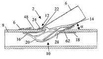
- FIG. 1shows a side view of an installed connector with a collar that secures a graft to the connector and affixes the connector and graft assembly to a vessel wall.
- FIG. 2shows a side-sectional view of the installed connector and collar in FIG. 1 .
- FIGS. 3 a and 3 bshow side and isometric views of a formed connector as may be used according to that shown in FIGS. 1 and 2 .
- FIGS. 4 a and 4 bshow side and perspective views of a non-formed connector blanks, which when formed represents the connector in FIGS. 3 a and b.
- FIG. 5shows a flattened view of the connector in FIGS. 4 a and b.
- FIG. 6shows a flattened view of an alternative connector embodiment.
- FIGS. 7 a and 7 bshow side and perspective views of the non-formed connector in FIG. 6 .
- FIG. 8shows a flattened view of another connector embodiment.
- FIG. 9 ashows a flattened view of a collar embodiment.
- FIGS. 9 b and 9 cshow side and perspective views of the collar embodiment in FIG. 9 a.
- FIGS. 10 a and 10 bshow side and perspective views of another collar embodiment.
- FIG. 11shows a flattened view of an alternative collar embodiment.
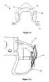
- FIGS. 12 a and 12 bshow side views of a delivery tool used to deflect the connector and collar assembly during deployment.
- the variations of the invention discussed hereinare applicable to robotic surgery and less invasive (i.e., minimally invasive) surgery involving a thoracostomy or mini median stemotomy to access the anastomosis site as well as the surgical approaches, such as that described below.
- the present inventionincludes variations of anastomosis connectors having features adapted to perform distal anastomoses. Anastomosis connectors, tools and associated methodology for producing proximal and distal anastomoses are described variously in U.S. and foreign patent and applications entitled, “Percutaneous Bypass Graft and Securing System”, U.S. Pat. No. 5,989,276; “Percutaneous Bypass Graft and Securing System”, U.S.
- FIGS. 1 and 2show distal anastomoses ( 2 ) formed by connectors ( 4 ) according to the present invention.
- Each connector ( 4 )attaches a graft ( 6 ) to a host vessel ( 8 ).
- the host vesselis a coronary artery.
- Graft ( 6 )preferably comprises a saphenous vein, radial artery, left internal mammary artery, or right internal mammary artery, though a synthetic graft (such as one made of expanded PTFE) can be utilized.
- the connector in FIG. 1includes a fitting (hidden) secured to the graft and the host vessel with a collar ( 12 ).
- FIG. 2shows a side-sectional view of the connector in FIG. 1 .
- fitting and attached graft ( 6 )are preferably configured so its base or body ( 14 ) is at an angle a with respect to host vessel ( 8 ).
- Connectors ( 2 )are shown at approximately a 30° angle.
- Preferred angles for distal anastomosisrange from about 20° to about 70°. A more preferable range is from about 30° to about 60°. Most preferably, they are between about 30° and about 45°. The angle may help maintain hemostasis and optimal blood flow once the anastomosis is created and retracted organs and tissue bear upon the site.
- Fitting ( 10 )may include at least a front or leading segment ( 16 ) and a rear or trailing segment ( 18 ). When situated to form an anastomosis, these segments preferably lie approximately in line with host vessel ( 8 ). So-placed, they prevent removal of the connector from the host vessel.
- Optional lateral or side portions ( 20 )may also aid in this regard. This is especially the case in forming an anastomosis with a very small diameter vessel (such as a 1 to 4 mm diameter coronary artery).
- lateral portions ( 20 )may assist in providing a physical barrier to leakage. This may be true irrespective of the size of host vessel ( 8 ).
- the use of one or more lateral portions ( 20 ) on each side of fitting ( 10 )may also provide a smooth transition between the leading and trailing portions of fitting ( 10 ) to help moderate or alleviate trauma to the interior of the host vessel ( 8 ).
- a lateral portionmay be provided integrally with a form providing at least part of leading segment ( 16 ) and trailing segment ( 18 ). This continuous coverage helps to ensures complete tissue capture between the fitting ( 10 ) inside the host vessel and the collar (not shown) outside the host vessel. Complete coverage ensures hemostasis at the vessel to graft interface.
- fitting ( 10 )Additional optional features include tabs ( 22 ) to assist in securing graft ( 6 ) and/or optional collar ( 12 ). Such tabs may be oriented to grip graft ( 6 ) as shown in FIG. 2 . One or more tabs may also be adapted to form a locking interface with one or more complementary tabs ( 24 ) optionally included in collar ( 12 ). Also, the height or amount of material incorporated in the base of the fitting may be varied. In order to utilize as little material as possible to join the various segments, base ( 14 ) may be provided by a narrow band of material as shown in FIGS. 3 a, 7 a or otherwise. To achieve proper relative placement of these features, base ( 14 ) may be curved or undulate.
- the connector opening ( 26 )may have an ovalized opening to the anastomosis or have a circular bore.
- the connectoris preferably fabricated from a raw tube that is laser cut into the desired pattern and thermally formed into the desired resting configuration as shown in FIGS. 3 a and 3 b.
- This inherent circular profilemay be altered by closing the width between opposite sides of the base ( 14 ) causing the connector to assume an ovalized profile with the major axis extending from the leading segment ( 16 ) towards the trailing segment ( 18 ) and the minor axis perpendicular to the major axis.
- Configuring fitting ( 10 ) with an ovalized opening ( 26 )may be useful in providing an interface at a smaller host vessel.
- Hinge section ( 28 )may be provided in a number of configurations. However, the configurations serve the same purpose.
- Each of the variations shown and describedallow rear segment ( 18 ) to be displaced sufficiently to clear the host vessel wall for insertion of the connector into the host vessel by significant torsional deflection of areas between rear segment ( 18 ) and fitting body ( 14 ).
- a pair of torsion sections ( 30 )are presented on each side of rear segment ( 18 ).
- hinge section ( 28 )may include only one torsion section ( 30 ) on each side of rear segment ( 18 ).
- the rotation about torsional sectionsmay account for a substantial amount of the displacement required of trailing segment ( 18 ).
- the additional displacementmay arise from bending of the trailing segment ( 18 ) relative to the junction between the trailing segment and the torsional sections.
- rotation of rear segment ( 18 )occurs about the pair of torsional members ( 30 )
- the rotation that occursis shared between two pair of torsional sections.
- FIGS. 2 , 3 a and 3 bSuch dual action provides for certain advantages notable in the variations shown in FIGS. 2 , 3 a and 3 b. Namely, upon forward deflection of rear segment ( 18 ), the lateral portions connected to torsional sections are caused to be drawn or flexed inward. This action facilitates introduction of connector ( 4 ) into host vessel ( 8 ) by clearing portions that could otherwise interfere with entry.
- the inherent design of the embodiment in FIGS. 2 , 3 a and 3 bmay require a pair of torsional sections on each side of the trailing section, one integrated with the base ( 14 ) and an opposite extending one integrated with the leading section ( 16 ).
- FIGS. 1The embodiment in FIGS.
- the trailing section ( 18 )may be integrated with the base and the leading section to provide a continuous band of support throughout the anastomosis along the interior surface of the host vessel, increase the resistance to deflection, once the connector is deployed, and providing a wedge between the trailing section ( 18 ) and the base ( 14 ) capable of increasing the compression forces that the trailing section ( 18 ) and the base ( 14 ) exert against the graft and the host vessel to ensure hemostasis at the heel of the anastomosis.
- FIGS. 1 , 9 a and 9 billustrate desirable features of this part of connector ( 4 ).
- One purpose of collar ( 12 )is to secure graft ( 6 ) to fitting ( 4 ) and ensure the graft produces a gasket against the host vessel throughout the periphery of the anastomosis to ensure hemostasis.
- optional collar tab(s) ( 24 )may assist in this regard by interfacing with optional fitting tab(s) ( 22 ).
- collar ( 12 )may be made to be resiliently biased against graft ( 6 ) to hold it to fitting ( 4 ).
- expansion spring members ( 35 )may be provided to enable expanding the diameter of the collar for placement around the fitting and returning the collar towards its preformed configuration once positioned to ensure a secure fit of collar ( 12 ) about fitting ( 6 ).
- the expansion spring members ( 35 ) in the embodiment in FIGS. 1 , 9 a and 9 bmay incorporate a vertical undulating pattern which straightens as the collar is expanded from its resting diameter towards an enlarged geometry and urges. Once the external force enlarging the collar is removed, the expanding spring members may recoil towards the undulating pattern urging the collar towards its resting, smaller diameter configuration.
- FIG. 11shows an alternative expansion spring member ( 35 ) which involves a horizontal undulating pattern.
- expansion spring member ( 35 )causes the central piece to deflect towards the base ( 14 ) of the fitting ensuring the collar maintains contact with the fitting despite enlargement or other deflection of the collar. This may become effective when the collar is deflected during deployment which may cause slight expansion of the collar to ensure separation between the collar components and the fitting during insertion into the host vessel, as will be discussed below. Provision of expansion spring members ( 35 ) eliminates any perceived need to use a locking member such as hook interlocking mechanism, a retaining clip, suture, implantable clips, staples, or other device that might be desired to ensure graft ( 6 ) is secured to fitting ( 4 ).
- a locking membersuch as hook interlocking mechanism, a retaining clip, suture, implantable clips, staples, or other device that might be desired to ensure graft ( 6 ) is secured to fitting ( 4 ).
- the distal band ( 39 ) of the collar ( 12 )extends completely around the anastomosis from the heel to the toe to overlap or interface with corresponding lateral features ( 20 ) of a complimentary fitting ( 10 ) to form a complete seal at an anastomosis site.
- the shape of the bore of the collar as shown in FIG. 9 cpreferably complements that of the fitting.
- the fittinghas a circular bore ( 26 )
- at least a mating portion of collar ( 12 )is preferably substantially circular as well.
- a corresponding shapeis preferably utilized in collar ( 12 ).
- the distal band ( 39 )is secured to the base of the collar at the heel to enable deflecting the distal band ( 39 ) upward during deployment.
- the semicircular nature of the distal band ( 39 )may cause the distal band to buckle outward as it is deflected with a deployment tool. This provides separation between the distal band ( 39 ) and the lateral sections ( 20 ) of the fitting to ensure host vessel tissue can enter this gap such that once positioned, the distal band may be released thereby compressing the graft and the host vessel against the fitting leading section and lateral section ensuring complete hemostasis around the periphery of the anastomosis.
- FIGS. 1 , 9 a – 9 cOther features of the collar ( 12 ) embodiment shown in FIGS. 1 , 9 a – 9 c involves side spring loops ( 33 ).
- These side spring loops ( 33 )may serve dual purposes: they may enable axial extension of the tab ( 24 ) during loading of the collar over the graft and the fitting to enable placing the tab ( 24 ) of the collar into engagement with the tab ( 22 ) of the fitting without requiring significant manipulation of the fitting and collar.
- the side spring loops ( 33 )may also provide an engagement point for pins of a deployment tool to stabilize the connector during deployment or a loading tool to manipulate the collar during placement of the graft and/or locking of the fitting to the collar.
- the side spring loops ( 33 )may or may not be thermally formed in a radially outward configuration such that the deployment tool pins may be readily inserted from the top, front, or rear, depending on the location of the pins on the deployment tool. As shown in FIGS. 10 a and 10 b, the side spring loops ( 33 ) may alternatively be fabricated without a loop but with horizontal (or vertical) undulating members that straighten as the tab ( 24 ) is extended relative to the base of the collar.
- the collar embodiments in FIGS. 9 a – 9 c and 10 a – 10 bmay also incorporate a grasping loop or link ( 31 ) that provides an exposed edge which the deployment tool may engage and deflect the distal band ( 39 ) relative to the base of the collar. The facilitates engagement and removal of the deployment tool relative to the collar.
- connector ( 4 )is preferably installed at an anastomosis site as shown in FIG. 2 .
- graft toe ( 48 )preferably overlaps host vessel ( 8 ).
- a heel portion ( 62 )may abut, overlap host vessel ( 8 ) or leave a slight gap.
- the visible resultwill resemble that in FIG. 1 .
- the preferred relation of graft ( 6 ) to host vessel ( 8 )remains similar to that shown in FIG. 2 , depending on the fitting configuration selected.
- a graft member ( 6 ) of sufficient lengthmay be obtained.
- thiswill be a saphenous vein.
- another harvested vesselsuch as the left internal mammary artery, right internal mammary artery, or radial artery
- a synthetic vessel or a donor vesselmay be used as a graft.
- the vesselis preferably sized to determine the appropriate connector size. This is preferably done with reference to the inner diameter ( 90 ) of the graft by inserting pins of increasing size (e.g. by 0.25 increments) until the graft no longer easily fits over a given pin. The size of the largest pin over which graft easily fits over sets the inner diameter of the graft.
- a connector for producing an anastomosis at a desired angleand having an appropriate size may be chosen.
- the size of fitting ( 10 ) and optional collar ( 12 )is preferably the first incremental size over the inner diameter of the graft. It is contemplated that connector component sizes may be sized to fit grafts of a diameter from about 2 mm to about 6 mm progressively, at 0.5 mm increments.
- a graftmay be skeletonized about 10 mm away from the end to be used in connection with the distal anastomosis. This may be accomplished by holding the adventitial tissue away from the graft with forceps and removing selected portions with Potts scissors. At this stage, graft ( 6 ) may be cut in such a manner as discussed above and advanced over fitting ( 10 ) into a position as depicted in FIG. 1 , or 2 .
- Advancing graft ( 6 ) through collar ( 12 )may be accomplished while holding the collar in an enlarged configuration with a loading tool or clamp (e.g., a hemostat) and using forceps to pull graft through collar. Then, the fitting ( 10 ) may be inserted through the cut end of the graft until the trailing segment of the fitting abuts the expansion spring of the collar. This ensures that the graft is completely captured between the fitting and the collar, which may be essential to ensuring hemostasis at the anastomosis.
- graft ( 6 )may be trimmed to more closely conform to the shape of connector elements, particularly the exterior of any collar ( 12 ) used. Trimming a graft in this manner may be particularly appropriate in instances where the graft used is simply prepared by taking a vessel, cutting it at 90° relative to its length and then creating a rear slit along its length as described above.
- fitting ( 10 )In placing fitting ( 10 ) into graft ( 6 ), it is to be set in relation to collar ( 12 ) in a complementary manner.
- tabs ( 22 ) and ( 24 )these features can easily be used to help align a fitting and a collar relative to each other. Either way, once collar ( 12 ) and fitting ( 10 ) are properly aligned, collar ( 12 ) may be released onto graft ( 6 ). Following this, any tabs and/or locking features ( 36 ) may be engaged with each other and a final check is made to ensure accurate component placement and graft coverage.
- a proximal connectorIn the event a proximal connector is to be used to complete a coronary bypass procedure, it may be connected to graft ( 6 ) in a similar fashion or as described variously in the references cited above. Still, as noted above, a distal connector may alone be used, with the proximal anastomosis to be accomplished otherwise. While it need not be the case, the distal connector will preferably be deployed before making the proximal connection.
- a graft/connector combinationis prepared, the assembly is then preferably engaged with a deployment device (not shown).
- connector ( 4 )be set and prepared for deployment within a deployment device, as shown in FIGS. 12 a and 12 b, before taking invasive action at the target site for a distal anastomosis.
- a distal anastomosis siteis prepared by creating an initial puncture, for instance, with the tip of a number 11 blade scalpel.
- this openingis preferably extended longitudinally with scissors to about 3 mm to 7 mm in length depending on the vessel size. Most often, a longitudinal slit of about 5 mm is preferred.
- Scissorsare advantageously provided in connection with an instrument. Otherwise, standard Potts scissors may be used.
- the deployment tool in FIG. 12 aincorporated pins ( 45 ) that may engage the spring loops of the collar. This provides stabilization of the connector relative to the deployment tool and provides a reference from which to deflect the distal band ( 39 ) of the collar. It should be noted that the deployment tool may alternatively incorporate a clamping or other grasping mechanism to engage the base of the collar and/or fitting without having to penetrate components of either the collar or fitting.
- a stabilization platform ( 47 )incorporated in the deployment tool and configured to engage the front and/or lateral surface of the connector to maintain the position of the connector during deployment.
- the deployment toolmay also incorporates a toe deflector ( 51 ) and a heel deflector ( 53 ) which deflect and release the distal band ( 39 ) of the collar and the trailing section ( 18 ) of the fitting during deployment.
- FIG. 12 ashows the toe deflector ( 51 ) and the heel deflector ( 53 ) in the loading or release state.
- FIG. 12 bshows the toe deflector ( 51 ) and the heel deflector ( 53 ) in the actuated state, ready for deployment of the connector. It should be noted that in FIG. 12 b, the components of the connector are not shown deflected; in operation, movement of the toe deflector and heel deflector may cause their counterparts on the connector to correspondingly deflect for deployment.
- the heel deflector and toe deflectorare released enabling the trailing section of the fitting and the distal band of the collar to return towards their resting configuration causing the tissue (host vessel and graft) residing between the fitting and the collar to be compressed, like a gasket, and ensure hemostasis at the anastomosis.
- tissuehost vessel and graft
- the toe deflector and the heel deflectormay be actuated simultaneously; the toe deflector may be offset from heel deflection to enable full deployment of the trailing section of the fitting prior to full release of the distal band of the collar; or may be operated independently.
- connector ( 4 )With the trailing segment and the distal band deflected into the deployment configuration, connector ( 4 ) is deployed. This is preferably performed by advancing leading section ( 16 ) through the arteriotomoy, and then such lateral features ( 20 ) of fitting ( 10 ) as may be provided. Deflected rear segment ( 18 ) may then be advanced into host vessel ( 8 ) and released to assume a position as shown in FIG. 2 in order to secure the connector. Particularly in those variations of the invention as described above where movement of rear segment articulates side portions ( 20 ), movement of rear segment ( 18 ) to an host-vessel engaging position will also cause affected side portions ( 20 ) to engage the sides of host vessel ( 8 ) to maintain connector ( 4 ) in place.
- a collar ( 12 )In instances when a collar ( 12 ) is used in connector ( 4 ), it may also be released to compress front portion ( 48 ) of graft ( 6 ) against host vessel ( 8 ). Release of collar ( 12 ) may also result in compressing graft ( 6 ) against portions of host vessel ( 8 ) opposed by lateral fitting portions ( 20 ), especially when the lateral portions are integrated with the trailing segment.
- the completed anastomosismay be checked for leakage. This may be done before and/or after an anastomosis at the proximal site is complete. At minimum, an inspection of the distal connection is preferably made when blood is flowing through graft ( 6 ). If leakage is detected and it cannot be remedied by adjustment of the graft or collar, the anastomosis site may be packed or bioglue (e.g., as available through Cryolife in Kennesaw, Ga.) or a stitch of suture material may be applied.
- biogluee.g., as available through Cryolife in Kennesaw, Ga.
- connector ( 4 )may be removed by reversing the procedure for its deployment.
- a preferred manner of producing connector components according to the present inventionis by machining tubing to include features that may be bent and set into shape to produce connector elements like those depicted in FIGS. 1 , 2 , 3 A, 3 B, 4 A, 4 B and 12 A. Shapes so produced may be referred to as wireforms.
- the machiningmay be accomplished by electron discharge machining (EDM), mechanically cutting, laser cutting or drilling, water-jet cutting or chemically etching.
- EDMelectron discharge machining
- portions of the connectorsmay be fabricated as separate components and bonded by spot welding, laser welding or other suitable manufacturing process to form complete structures.
- the materialmay be set in a desired final shape. Where a metal is used, one or more flexure steps followed by heating will accomplish this.
- the connector elementsare made of alternate material such as a plastic or a composite, other forming procedures as would be apparent to one with skill in the art may be used.
- connector elementsare made from a metal (e.g., titanium) or metal alloy (e.g., stainless steel or nickel titanium).
- metal alloye.g., stainless steel or nickel titanium
- Other materialssuch as thermoplastic (e.g., PTFE), thermoset plastic (e.g., polyethylene terephthalate, or polyester), silicone or combination of the aforementioned materials into a composite structure may alternatively be used.
- connectors fabricated from nickel titaniummay be clad with expanded PTFE, polyester, PET, or other material that may have a woven or porous surface.
- the fittingsmay be coated with materials such as paralyne or other hydrophilic substrates that are biologically inert and reduce the surface friction.
- metallic or metallic alloy fittingsmay be electropolished.
- the fittingsmay be coated with heparin, thromboresistance substances (e.g., glycoprotein IIb/IIIa inhibitors), antiproliferative substances (e.g., rapamycin), or other coatings designed to prevent thrombosis, hyperplasia, or platelet congregation around the attachment point between the bypass graft and the host vessel.
- thromboresistance substancese.g., glycoprotein IIb/IIIa inhibitors
- antiproliferative substancese.g., rapamycin
- a materialsuch as platinum, gold, tantalum, tin, tin-indium, zirconium, zirconium alloy, zirconium oxide, zirconium nitrate, phosphatidyl-choline, or other material, may be deposited onto the fitting surface using electroplating, sputtering vacuum evaporation, ion assisted beam deposition, vapor deposition, silver doping, boronation techniques, a salt bath, or other coating process.
- a still further improvement of the fittingsis to include beta or gamma radiation sources on the end-side fittings.
- a beta or gamma source isotope having an average half-life of approximately 15 dayssuch as Phosphorous 32 or Paladium 103 may be placed on the base and/or petals of the end-side fitting using an ionimplantation process, chemical adhesion process, or other suitable method. Further details as to optional treatments of connectors according to the present invention are described in 10.00. Of course, connector fitting ( 10 ) and any associated collar ( 12 ) may be made differently. To avoid electrolytic corrosion, however, dissimilar metals should not be used.
- NiTi (Nitinol) tubing or flat stockmay be used to produce connector components.
- a preferred alloyincludes a 54.5–57% Ni content, and a remainder Ti by weight (less minor amounts of C, O, Al, Co, Cu, Fe, Mn, No, Nb, Si and W) is used.
- Such alloyhas an A f for at about ⁇ 10 to ⁇ 15° C. Consequently, for typical handling and in use, the material will exhibit superelastic properties as is most desired.
- connectors according to the present inventionmay utilize thermoelastic or shape memory characteristics instead, wherein the material of either or both fitting ( 10 ) and connector ( 12 ) change from a martinsitic state to an austenitic state upon introduction to an anastomosis site and exposure to a sufficiently warm environment. Taking advantage of the martinsitic state of such an alloy will ease deflecting rear segment ( 18 ) and distal band ( 39 ) and maintaining their positions until placement.
- thermoelastic or superelastic propertiesmakes for a connector that can have certain members stressed to a high degree and return without permanent deformation from a desired position.
- fitting ( 10 ) and collar ( 12 )may be made of more typical materials such as stainless steel or plastic.
- Hinge section ( 28 )may permit designs in which the stress applied by torsion is lower that applied in simply deflecting a rear petal or segment as shown and described in U.S. and foreign patents and applications entitled, “Improved Anastomosis Systems”, U.S. patent application Ser. No.
- FIGS. 5 , 4 a – 4 b, and 3 a – 3 bshow views of a connector fitting ( 10 ) at different stages of production being made from tubing.
- FIG. 5shows the flattened profile of the tubing laser cutting to obtain the fitting blank.
- FIGS. 4 a and 4 bshow the laser cut fitting blank.
- FIGS. 3 a and 3 bshow the thermally formed fitting.
- the tube stock used to prepare distal connector fittingpreferably has an outer diameter between 0.080 and 0.240 in (2 to 6 mm) and a wall thickness between 0.004 and 0.008 in (0.1 to 0.2 mm). Slightly larger diameter stock (or end product) will be used for each matching collar.
- the stock thickness for NiTi material used to form collarswill typically have a wall thickness between about 0.004 in and about 0.008 in, and preferably between about 0.006 in and about 0.010 in.
- thiswill be preferred in order to minimally obstruct blood flow past the fitting.
- Larger connector componentswill typically be made of thick stock to account for increased stiffness required of such configurations relative to smaller ones.
Landscapes
- Health & Medical Sciences (AREA)
- Life Sciences & Earth Sciences (AREA)
- Surgery (AREA)
- Heart & Thoracic Surgery (AREA)
- Engineering & Computer Science (AREA)
- Biomedical Technology (AREA)
- Nuclear Medicine, Radiotherapy & Molecular Imaging (AREA)
- Medical Informatics (AREA)
- Molecular Biology (AREA)
- Animal Behavior & Ethology (AREA)
- General Health & Medical Sciences (AREA)
- Public Health (AREA)
- Veterinary Medicine (AREA)
- Surgical Instruments (AREA)
Abstract
Description
Claims (45)
Priority Applications (6)
| Application Number | Priority Date | Filing Date | Title |
|---|---|---|---|
| US10/122,075US6972023B2 (en) | 2001-07-05 | 2002-04-11 | Distal anastomosis system |
| PCT/US2002/020846WO2003005698A2 (en) | 2001-07-05 | 2002-07-01 | Distal anastomosis system |
| JP2003511527AJP2004534585A (en) | 2001-07-05 | 2002-07-01 | Distal anastomosis system |
| EP02749734AEP1408851A2 (en) | 2001-07-05 | 2002-07-01 | Distal anastomosis system |
| AU2002320230AAU2002320230A1 (en) | 2001-07-05 | 2002-07-01 | Distal anastomosis system |
| CA002450407ACA2450407A1 (en) | 2001-07-05 | 2002-07-01 | Distal anastomosis system |
Applications Claiming Priority (3)
| Application Number | Priority Date | Filing Date | Title |
|---|---|---|---|
| US09/899,346US6626920B2 (en) | 2001-07-05 | 2001-07-05 | Distal anastomosis system |
| US33327601P | 2001-11-14 | 2001-11-14 | |
| US10/122,075US6972023B2 (en) | 2001-07-05 | 2002-04-11 | Distal anastomosis system |
Related Parent Applications (1)
| Application Number | Title | Priority Date | Filing Date |
|---|---|---|---|
| US09/899,346Continuation-In-PartUS6626920B2 (en) | 2001-07-05 | 2001-07-05 | Distal anastomosis system |
Publications (2)
| Publication Number | Publication Date |
|---|---|
| US20030093095A1 US20030093095A1 (en) | 2003-05-15 |
| US6972023B2true US6972023B2 (en) | 2005-12-06 |
Family
ID=26820127
Family Applications (1)
| Application Number | Title | Priority Date | Filing Date |
|---|---|---|---|
| US10/122,075Expired - Fee RelatedUS6972023B2 (en) | 2001-07-05 | 2002-04-11 | Distal anastomosis system |
Country Status (1)
| Country | Link |
|---|---|
| US (1) | US6972023B2 (en) |
Cited By (123)
| Publication number | Priority date | Publication date | Assignee | Title |
|---|---|---|---|---|
| US20040049212A1 (en)* | 2001-07-05 | 2004-03-11 | Converge Medical, Inc. | Distal anastomosis system |
| US20060206123A1 (en)* | 2004-08-27 | 2006-09-14 | Rox Medical, Inc. | Device and method for establishing an artificial arterio-venous fistula |
| US20070249985A1 (en)* | 2004-08-27 | 2007-10-25 | Rox Medical, Inc. | Device and method for establishing an artificial arterio-venous fistula |
| US7351247B2 (en) | 2002-09-04 | 2008-04-01 | Bioconnect Systems, Inc. | Devices and methods for interconnecting body conduits |
| US20090143793A1 (en)* | 2007-11-29 | 2009-06-04 | Nanyang Technological University | Connector for surgical anastomoses |
| US7637917B2 (en) | 2004-10-08 | 2009-12-29 | Tyco Healthcare Group Lp | Endoscopic surgical clip applier |
| USD625009S1 (en) | 2006-03-24 | 2010-10-05 | Tyco Healthcare Group Lp | Surgical clip applier |
| US20100268316A1 (en)* | 2004-08-27 | 2010-10-21 | Rox Medical, Inc. | Device and method for establishing an artificial arterio-venous fistula |
| US7819886B2 (en) | 2004-10-08 | 2010-10-26 | Tyco Healthcare Group Lp | Endoscopic surgical clip applier |
| USD629101S1 (en) | 2006-03-24 | 2010-12-14 | Tyco Healthcare Group Lp | Surgical clip applier |
| US7892246B2 (en) | 1999-07-28 | 2011-02-22 | Bioconnect Systems, Inc. | Devices and methods for interconnecting conduits and closing openings in tissue |
| US7892247B2 (en) | 2001-10-03 | 2011-02-22 | Bioconnect Systems, Inc. | Devices and methods for interconnecting vessels |
| US8056565B2 (en) | 2008-08-25 | 2011-11-15 | Tyco Healthcare Group Lp | Surgical clip applier and method of assembly |
| US8128643B2 (en) | 2006-10-17 | 2012-03-06 | Tyco Healthcare Group Lp | Apparatus for applying surgical clips |
| US8162963B2 (en)* | 2004-06-17 | 2012-04-24 | Maquet Cardiovascular Llc | Angled anastomosis device, tools and method of using |
| US20120123454A1 (en)* | 2010-11-11 | 2012-05-17 | Wilson T. Asfora | Sutureless vascular anastomosis connection |
| US8267944B2 (en) | 2008-08-29 | 2012-09-18 | Tyco Healthcare Group Lp | Endoscopic surgical clip applier with lock out |
| US8366651B2 (en) | 2007-08-02 | 2013-02-05 | Bioconnect Systems, Inc. | Implantable flow connector |
| US8382773B2 (en) | 2007-03-26 | 2013-02-26 | Covidien Lp | Endoscopic surgical clip applier |
| US8394114B2 (en) | 2003-09-26 | 2013-03-12 | Medtronic, Inc. | Surgical connection apparatus and methods |
| US8403946B2 (en) | 2010-07-28 | 2013-03-26 | Covidien Lp | Articulating clip applier cartridge |
| US8403945B2 (en) | 2010-02-25 | 2013-03-26 | Covidien Lp | Articulating endoscopic surgical clip applier |
| US8409222B2 (en) | 2004-10-08 | 2013-04-02 | Covidien Lp | Endoscopic surgical clip applier |
| US8409223B2 (en) | 2008-08-29 | 2013-04-02 | Covidien Lp | Endoscopic surgical clip applier with clip retention |
| US8465502B2 (en) | 2008-08-25 | 2013-06-18 | Covidien Lp | Surgical clip applier and method of assembly |
| US8506580B2 (en) | 2007-04-11 | 2013-08-13 | Covidien Lp | Surgical clip applier |
| US8545486B2 (en) | 2009-12-15 | 2013-10-01 | Covidien Lp | Surgical clip applier |
| US8585717B2 (en) | 2008-08-29 | 2013-11-19 | Covidien Lp | Single stroke endoscopic surgical clip applier |
| US8652152B2 (en) | 2004-09-23 | 2014-02-18 | Covidien Lp | Clip applying apparatus and ligation clip |
| US8734469B2 (en) | 2009-10-13 | 2014-05-27 | Covidien Lp | Suture clip applier |
| US8900253B2 (en) | 2003-03-11 | 2014-12-02 | Covidien Lp | Clip applying apparatus with angled jaw |
| US8920438B2 (en) | 2004-10-08 | 2014-12-30 | Covidien Lp | Apparatus for applying surgical clips |
| US8932341B2 (en) | 2004-08-27 | 2015-01-13 | Rox Medical, Inc. | Method for establishing an artificial arterio-venous fistula |
| US8968337B2 (en) | 2010-07-28 | 2015-03-03 | Covidien Lp | Articulating clip applier |
| US9011464B2 (en) | 2010-11-02 | 2015-04-21 | Covidien Lp | Self-centering clip and jaw |
| US9113892B2 (en) | 2013-01-08 | 2015-08-25 | Covidien Lp | Surgical clip applier |
| US9186136B2 (en) | 2009-12-09 | 2015-11-17 | Covidien Lp | Surgical clip applier |
| US9186153B2 (en) | 2011-01-31 | 2015-11-17 | Covidien Lp | Locking cam driver and jaw assembly for clip applier |
| US9282967B2 (en) | 2007-08-02 | 2016-03-15 | Bioconnect Systems, Inc. | Implantable flow connector |
| US9314600B2 (en) | 2012-04-15 | 2016-04-19 | Bioconnect Systems, Inc. | Delivery system for implantable flow connector |
| US9358015B2 (en) | 2008-08-29 | 2016-06-07 | Covidien Lp | Endoscopic surgical clip applier with wedge plate |
| US9364239B2 (en) | 2011-12-19 | 2016-06-14 | Covidien Lp | Jaw closure mechanism for a surgical clip applier |
| US9364216B2 (en) | 2011-12-29 | 2016-06-14 | Covidien Lp | Surgical clip applier with integrated clip counter |
| US9408610B2 (en) | 2012-05-04 | 2016-08-09 | Covidien Lp | Surgical clip applier with dissector |
| US9414844B2 (en) | 2008-08-25 | 2016-08-16 | Covidien Lp | Surgical clip appliers |
| US9532787B2 (en) | 2012-05-31 | 2017-01-03 | Covidien Lp | Endoscopic clip applier |
| US9750500B2 (en) | 2013-01-18 | 2017-09-05 | Covidien Lp | Surgical clip applier |
| US9763668B2 (en) | 2004-10-08 | 2017-09-19 | Covidien Lp | Endoscopic surgical clip applier |
| US9775623B2 (en) | 2011-04-29 | 2017-10-03 | Covidien Lp | Surgical clip applier including clip relief feature |
| US9775624B2 (en) | 2013-08-27 | 2017-10-03 | Covidien Lp | Surgical clip applier |
| US9931124B2 (en) | 2015-01-07 | 2018-04-03 | Covidien Lp | Reposable clip applier |
| US9968362B2 (en) | 2013-01-08 | 2018-05-15 | Covidien Lp | Surgical clip applier |
| US10159485B2 (en) | 2010-11-11 | 2018-12-25 | Asfora Ip, Llc | Deployment tool for sutureless vascular anastomosis connection |
| US10159491B2 (en) | 2015-03-10 | 2018-12-25 | Covidien Lp | Endoscopic reposable surgical clip applier |
| US10292712B2 (en) | 2015-01-28 | 2019-05-21 | Covidien Lp | Surgical clip applier with integrated cutter |
| US10390831B2 (en) | 2015-11-10 | 2019-08-27 | Covidien Lp | Endoscopic reposable surgical clip applier |
| US10426489B2 (en) | 2016-11-01 | 2019-10-01 | Covidien Lp | Endoscopic reposable surgical clip applier |
| US10434293B2 (en) | 2012-04-15 | 2019-10-08 | Tva Medical, Inc. | Implantable flow connector |
| US10492795B2 (en) | 2016-11-01 | 2019-12-03 | Covidien Lp | Endoscopic surgical clip applier |
| US10548602B2 (en) | 2017-02-23 | 2020-02-04 | Covidien Lp | Endoscopic surgical clip applier |
| US10582931B2 (en) | 2016-02-24 | 2020-03-10 | Covidien Lp | Endoscopic reposable surgical clip applier |
| US10603038B2 (en) | 2017-02-22 | 2020-03-31 | Covidien Lp | Surgical clip applier including inserts for jaw assembly |
| US10610236B2 (en) | 2016-11-01 | 2020-04-07 | Covidien Lp | Endoscopic reposable surgical clip applier |
| US10639044B2 (en) | 2016-10-31 | 2020-05-05 | Covidien Lp | Ligation clip module and clip applier |
| US10639032B2 (en) | 2017-06-30 | 2020-05-05 | Covidien Lp | Endoscopic surgical clip applier including counter assembly |
| US10653429B2 (en) | 2017-09-13 | 2020-05-19 | Covidien Lp | Endoscopic surgical clip applier |
| US10660725B2 (en) | 2017-02-14 | 2020-05-26 | Covidien Lp | Endoscopic surgical clip applier including counter assembly |
| US10660651B2 (en) | 2016-10-31 | 2020-05-26 | Covidien Lp | Endoscopic reposable surgical clip applier |
| US10660723B2 (en) | 2017-06-30 | 2020-05-26 | Covidien Lp | Endoscopic reposable surgical clip applier |
| US10675043B2 (en) | 2017-05-04 | 2020-06-09 | Covidien Lp | Reposable multi-fire surgical clip applier |
| US10675112B2 (en) | 2017-08-07 | 2020-06-09 | Covidien Lp | Endoscopic surgical clip applier including counter assembly |
| US10702280B2 (en) | 2015-11-10 | 2020-07-07 | Covidien Lp | Endoscopic reposable surgical clip applier |
| US10702278B2 (en) | 2014-12-02 | 2020-07-07 | Covidien Lp | Laparoscopic surgical ligation clip applier |
| US10702279B2 (en) | 2015-11-03 | 2020-07-07 | Covidien Lp | Endoscopic surgical clip applier |
| US10709455B2 (en) | 2017-02-02 | 2020-07-14 | Covidien Lp | Endoscopic surgical clip applier |
| US10722236B2 (en) | 2017-12-12 | 2020-07-28 | Covidien Lp | Endoscopic reposable surgical clip applier |
| US10722235B2 (en) | 2017-05-11 | 2020-07-28 | Covidien Lp | Spring-release surgical clip |
| US10743887B2 (en) | 2017-12-13 | 2020-08-18 | Covidien Lp | Reposable multi-fire surgical clip applier |
| US10758244B2 (en) | 2017-02-06 | 2020-09-01 | Covidien Lp | Endoscopic surgical clip applier |
| US10758245B2 (en) | 2017-09-13 | 2020-09-01 | Covidien Lp | Clip counting mechanism for surgical clip applier |
| US10765431B2 (en) | 2016-01-18 | 2020-09-08 | Covidien Lp | Endoscopic surgical clip applier |
| US10786262B2 (en) | 2017-08-09 | 2020-09-29 | Covidien Lp | Endoscopic reposable surgical clip applier |
| US10786273B2 (en) | 2018-07-13 | 2020-09-29 | Covidien Lp | Rotation knob assemblies for handle assemblies |
| US10786263B2 (en) | 2017-08-15 | 2020-09-29 | Covidien Lp | Endoscopic reposable surgical clip applier |
| US10806463B2 (en) | 2011-11-21 | 2020-10-20 | Covidien Lp | Surgical clip applier |
| US10806464B2 (en) | 2016-08-11 | 2020-10-20 | Covidien Lp | Endoscopic surgical clip applier and clip applying systems |
| US10828036B2 (en) | 2017-11-03 | 2020-11-10 | Covidien Lp | Endoscopic surgical clip applier and handle assemblies for use therewith |
| US10835260B2 (en) | 2017-09-13 | 2020-11-17 | Covidien Lp | Endoscopic surgical clip applier and handle assemblies for use therewith |
| US10835341B2 (en) | 2017-09-12 | 2020-11-17 | Covidien Lp | Endoscopic surgical clip applier and handle assemblies for use therewith |
| US10849630B2 (en) | 2017-12-13 | 2020-12-01 | Covidien Lp | Reposable multi-fire surgical clip applier |
| US10863992B2 (en) | 2017-08-08 | 2020-12-15 | Covidien Lp | Endoscopic surgical clip applier |
| US10905425B2 (en) | 2015-11-10 | 2021-02-02 | Covidien Lp | Endoscopic reposable surgical clip applier |
| US10932793B2 (en) | 2016-01-11 | 2021-03-02 | Covidien Lp | Endoscopic reposable surgical clip applier |
| US10932791B2 (en) | 2017-11-03 | 2021-03-02 | Covidien Lp | Reposable multi-fire surgical clip applier |
| US10932790B2 (en) | 2017-08-08 | 2021-03-02 | Covidien Lp | Geared actuation mechanism and surgical clip applier including the same |
| US10945734B2 (en) | 2017-11-03 | 2021-03-16 | Covidien Lp | Rotation knob assemblies and surgical instruments including the same |
| US10959737B2 (en) | 2017-12-13 | 2021-03-30 | Covidien Lp | Reposable multi-fire surgical clip applier |
| US10993721B2 (en) | 2018-04-25 | 2021-05-04 | Covidien Lp | Surgical clip applier |
| US11033256B2 (en) | 2018-08-13 | 2021-06-15 | Covidien Lp | Linkage assembly for reusable surgical handle assemblies |
| US11051827B2 (en) | 2018-01-16 | 2021-07-06 | Covidien Lp | Endoscopic surgical instrument and handle assemblies for use therewith |
| US11051828B2 (en) | 2018-08-13 | 2021-07-06 | Covidien Lp | Rotation knob assemblies and surgical instruments including same |
| US11058432B2 (en) | 2015-01-15 | 2021-07-13 | Covidien Lp | Endoscopic reposable surgical clip applier |
| US11071553B2 (en) | 2016-08-25 | 2021-07-27 | Covidien Lp | Endoscopic surgical clip applier and clip applying systems |
| US11116514B2 (en) | 2017-02-06 | 2021-09-14 | Covidien Lp | Surgical clip applier with user feedback feature |
| US11116513B2 (en) | 2017-11-03 | 2021-09-14 | Covidien Lp | Modular surgical clip cartridge |
| US11147566B2 (en) | 2018-10-01 | 2021-10-19 | Covidien Lp | Endoscopic surgical clip applier |
| US11207457B2 (en)* | 2004-08-27 | 2021-12-28 | Edwards Lifesciences Corporation | Device and method for establishing an artificial arterio-venous fistula |
| US11219463B2 (en) | 2018-08-13 | 2022-01-11 | Covidien Lp | Bilateral spring for surgical instruments and surgical instruments including the same |
| US11246601B2 (en) | 2018-08-13 | 2022-02-15 | Covidien Lp | Elongated assemblies for surgical clip appliers and surgical clip appliers incorporating the same |
| US11253267B2 (en) | 2018-08-13 | 2022-02-22 | Covidien Lp | Friction reduction mechanisms for handle assemblies |
| US11259887B2 (en) | 2018-08-10 | 2022-03-01 | Covidien Lp | Feedback mechanisms for handle assemblies |
| US11278267B2 (en) | 2018-08-13 | 2022-03-22 | Covidien Lp | Latch assemblies and surgical instruments including the same |
| US11344316B2 (en) | 2018-08-13 | 2022-05-31 | Covidien Lp | Elongated assemblies for surgical clip appliers and surgical clip appliers incorporating the same |
| US11376015B2 (en) | 2017-11-03 | 2022-07-05 | Covidien Lp | Endoscopic surgical clip applier and handle assemblies for use therewith |
| US11524398B2 (en) | 2019-03-19 | 2022-12-13 | Covidien Lp | Gear drive mechanisms for surgical instruments |
| US11583291B2 (en) | 2017-02-23 | 2023-02-21 | Covidien Lp | Endoscopic surgical clip applier |
| US11723669B2 (en) | 2020-01-08 | 2023-08-15 | Covidien Lp | Clip applier with clip cartridge interface |
| US11779340B2 (en) | 2020-01-02 | 2023-10-10 | Covidien Lp | Ligation clip loading device |
| US11918223B2 (en) | 2018-02-02 | 2024-03-05 | University Of Louisville Research Foundation, Inc. | Sutureless graft anastomotic quick connect system |
| US12114866B2 (en) | 2020-03-26 | 2024-10-15 | Covidien Lp | Interoperative clip loading device |
| US12408907B1 (en) | 2019-11-14 | 2025-09-09 | Edwards Lifesciences Corporation | Method of reducing left atrial pressure |
| US12414797B2 (en) | 2019-08-22 | 2025-09-16 | Edwards Lifesciences Corporation | Puncture needles |
| US12419648B2 (en) | 2022-09-26 | 2025-09-23 | Covidien Lp | Two-part fasteners for surgical clip appliers and surgical clip appliers for deploying the same |
Citations (128)
| Publication number | Priority date | Publication date | Assignee | Title |
|---|---|---|---|---|
| US4214587A (en) | 1979-02-12 | 1980-07-29 | Sakura Chester Y Jr | Anastomosis device and method |
| US4366819A (en) | 1980-11-17 | 1983-01-04 | Kaster Robert L | Anastomotic fitting |
| US4368736A (en) | 1980-11-17 | 1983-01-18 | Kaster Robert L | Anastomotic fitting |
| US4607637A (en) | 1983-07-22 | 1986-08-26 | Anders Berggren | Surgical instrument for performing anastomosis with the aid of ring-like fastening elements and the fastening elements for performing anastomosis |
| US4624257A (en) | 1982-06-24 | 1986-11-25 | Anders Berggren | Surgical instrument for performing anastomosis |
| US4657019A (en) | 1984-04-10 | 1987-04-14 | Idea Research Investment Fund, Inc. | Anastomosis devices and kits |
| US4665906A (en) | 1983-10-14 | 1987-05-19 | Raychem Corporation | Medical devices incorporating sim alloy elements |
| US4787386A (en) | 1984-04-10 | 1988-11-29 | Idea Research Investment Fund, Inc. | Anastomosis devices, and kits |
| US4917091A (en) | 1982-06-24 | 1990-04-17 | Unilink Ab | Annular fastening means |
| US4917087A (en) | 1984-04-10 | 1990-04-17 | Walsh Manufacturing (Mississuaga) Limited | Anastomosis devices, kits and method |
| US4950227A (en) | 1988-11-07 | 1990-08-21 | Boston Scientific Corporation | Stent delivery system |
| US5067957A (en) | 1983-10-14 | 1991-11-26 | Raychem Corporation | Method of inserting medical devices incorporating SIM alloy elements |
| US5078736A (en) | 1990-05-04 | 1992-01-07 | Interventional Thermodynamics, Inc. | Method and apparatus for maintaining patency in the body passages |
| US5156613A (en) | 1991-02-13 | 1992-10-20 | Interface Biomedical Laboratories Corp. | Collagen welding rod material for use in tissue welding |
| US5190546A (en) | 1983-10-14 | 1993-03-02 | Raychem Corporation | Medical devices incorporating SIM alloy elements |
| US5234447A (en) | 1990-08-28 | 1993-08-10 | Robert L. Kaster | Side-to-end vascular anastomotic staple apparatus |
| US5391156A (en) | 1992-06-30 | 1995-02-21 | Ethicon, Inc. | Flexible encoscopic surgical port |
| US5405322A (en) | 1993-08-12 | 1995-04-11 | Boston Scientific Corporation | Method for treating aneurysms with a thermal source |
| US5443497A (en) | 1993-11-22 | 1995-08-22 | The Johns Hopkins University | Percutaneous prosthetic by-pass graft and method of use |
| US5503635A (en) | 1993-11-12 | 1996-04-02 | United States Surgical Corporation | Apparatus and method for performing compressional anastomoses |
| WO1996022745A1 (en) | 1995-01-23 | 1996-08-01 | Schneider (Usa) Inc. | Percutaneous stent-graft and method for delivery thereof |
| US5571167A (en) | 1991-07-03 | 1996-11-05 | Maginot; Thomas J. | Bypass grafting method |
| WO1997013463A1 (en) | 1995-10-13 | 1997-04-17 | Transvascular, Inc. | Methods and apparatus for bypassing arterial obstructions and/or performing other transvascular procedures |
| WO1997013471A1 (en) | 1995-10-13 | 1997-04-17 | Transvascular, Inc. | A device, system and method for interstitial transvascular intervention |
| WO1997016122A1 (en) | 1995-10-31 | 1997-05-09 | Oticon A/S | Method and anastomotic instrument for use when performing an end-to-side anastomosis |
| US5628784A (en) | 1994-01-18 | 1997-05-13 | Strecker; Ernst P. | Endoprosthesis that can be percutaneously implanted in the body of a patient |
| WO1997027893A1 (en) | 1996-02-02 | 1997-08-07 | Transvascular, Inc. | Methods and apparatus for blocking flow through blood vessels |
| WO1997027898A1 (en) | 1996-02-02 | 1997-08-07 | Transvascular, Inc. | Methods and apparatus for connecting openings formed in adjacent blood vessels or other anatomical structures |
| WO1997027897A1 (en) | 1996-02-02 | 1997-08-07 | Transvascular, Inc. | A device, system and method for interstitial transvascular intervention |
| US5657429A (en) | 1992-08-10 | 1997-08-12 | Computer Motion, Inc. | Automated endoscope system optimal positioning |
| WO1997031575A1 (en) | 1996-02-29 | 1997-09-04 | Oticon A/S | Method and anastomotic instrument for use when performing an end-to-side anastomosis |
| US5665117A (en) | 1995-11-27 | 1997-09-09 | Rhodes; Valentine J. | Endovascular prosthesis with improved sealing means for aneurysmal arterial disease and method of use |
| US5669934A (en) | 1991-02-13 | 1997-09-23 | Fusion Medical Technologies, Inc. | Methods for joining tissue by applying radiofrequency energy to performed collagen films and sheets |
| US5676670A (en) | 1996-06-14 | 1997-10-14 | Beth Israel Deaconess Medical Center | Catheter apparatus and method for creating a vascular bypass in-vivo |
| US5690675A (en) | 1991-02-13 | 1997-11-25 | Fusion Medical Technologies, Inc. | Methods for sealing of staples and other fasteners in tissue |
| WO1997043961A1 (en) | 1996-05-17 | 1997-11-27 | Jan Otto Solem | A by-pass graft |
| US5695504A (en) | 1995-02-24 | 1997-12-09 | Heartport, Inc. | Devices and methods for performing a vascular anastomosis |
| US5697968A (en) | 1995-08-10 | 1997-12-16 | Aeroquip Corporation | Check valve for intraluminal graft |
| US5702418A (en) | 1995-09-12 | 1997-12-30 | Boston Scientific Corporation | Stent delivery system |
| WO1998003118A1 (en) | 1996-07-24 | 1998-01-29 | Jan Otto Solem | Anastomotic fitting |
| US5713917A (en) | 1995-10-30 | 1998-02-03 | Leonhardt; Howard J. | Apparatus and method for engrafting a blood vessel |
| WO1998006356A1 (en) | 1996-08-13 | 1998-02-19 | Heartstent Corporation | Method and apparatus for performing coronary artery bypass surgery |
| US5720755A (en) | 1995-01-18 | 1998-02-24 | Dakov; Pepi | Tubular suturing device and methods of use |
| WO1998007399A1 (en) | 1996-08-23 | 1998-02-26 | Beth Israel Deaconess Medical Center | CATHETER APPARATUS AND METHOD USING A SHAPE-MEMORY ALLOY CUFF FOR CREATING A BYPASS GRAFT $i(IN VIVO) |
| WO1998008456A1 (en) | 1996-08-26 | 1998-03-05 | Transvascular, Inc. | Methods and apparatus for transmyocardial direct coronary revascularization |
| US5725544A (en) | 1993-12-23 | 1998-03-10 | Oticon A/S | Method and instrument for establishing the receiving site of a coronary artery bypass graft |
| US5728133A (en) | 1996-07-09 | 1998-03-17 | Cardiologics, L.L.C. | Anchoring device and method for sealing percutaneous punctures in vessels |
| US5749895A (en) | 1991-02-13 | 1998-05-12 | Fusion Medical Technologies, Inc. | Method for bonding or fusion of biological tissue and material |
| WO1998019618A1 (en) | 1996-11-07 | 1998-05-14 | Vascular Science Inc. | Tubular body structure marking methods and apparatus |
| WO1998019631A1 (en) | 1996-11-07 | 1998-05-14 | Vascular Science Inc. | Artificial medical graft methods and apparatus |
| WO1998019634A2 (en) | 1996-11-07 | 1998-05-14 | Vascular Science Inc. | Medical grafting methods and apparatus |
| WO1998019632A1 (en) | 1996-11-07 | 1998-05-14 | Vascular Science Inc. | Artificial tubular body organ grafts |
| WO1998019635A1 (en) | 1996-11-07 | 1998-05-14 | Vascular Science Inc. | Methods and apparatus for handling tubing used in medical procedures |
| WO1998019608A1 (en) | 1996-11-07 | 1998-05-14 | Vascular Science Inc. | Medical instrument with extendable snare |
| WO1998019732A1 (en) | 1996-11-07 | 1998-05-14 | Vascular Science Inc. | Steerable instrument for use in medical procedures |
| US5755778A (en) | 1996-10-16 | 1998-05-26 | Nitinol Medical Technologies, Inc. | Anastomosis device |
| US5762458A (en) | 1996-02-20 | 1998-06-09 | Computer Motion, Inc. | Method and apparatus for performing minimally invasive cardiac procedures |
| WO1998019625A3 (en) | 1996-11-08 | 1998-07-02 | Russell A Houser | Percutaneous bypass graft and securing system |
| US5779718A (en) | 1992-10-09 | 1998-07-14 | United States Surgical Corporation | Method of anastomosing a vessel using a surgical clip applier |
| WO1998038939A1 (en) | 1997-03-06 | 1998-09-11 | Scimed Life Systems, Inc. | Percutaneous bypass with branching vessel |
| WO1998038941A1 (en) | 1997-03-06 | 1998-09-11 | Scimed Life Systems, Inc. | System and method for percutaneous coronary artery bypass |
| WO1998019629A3 (en) | 1996-11-07 | 1998-09-11 | Vascular Science Inc | Medical grafting connectors and fasteners |
| WO1998040036A1 (en) | 1997-03-13 | 1998-09-17 | United States Surgical Corporation | Graft attachment assembly |
| US5810884A (en) | 1996-09-09 | 1998-09-22 | Beth Israel Deaconess Medical Center | Apparatus and method for closing a vascular perforation after percutaneous puncture of a blood vessel in a living subject |
| US5814005A (en) | 1991-12-23 | 1998-09-29 | Ela Medical S.A. | Ventricular cannulation device |
| WO1998042262A1 (en) | 1997-03-26 | 1998-10-01 | Perclose, Inc. | Device and method for suturing tissue |
| WO1998019636A3 (en) | 1996-11-07 | 1998-10-08 | Vascular Science Inc | Medical grafting methods and apparatus |
| WO1998019630A3 (en) | 1996-11-07 | 1998-10-08 | Vascular Science Inc | Tubular medical graft connectors |
| US5824015A (en) | 1991-02-13 | 1998-10-20 | Fusion Medical Technologies, Inc. | Method for welding biological tissue |
| WO1998052474A1 (en) | 1997-05-22 | 1998-11-26 | Kensey Nash Corporation | Anastomosis system and method of use |
| WO1998057592A1 (en) | 1997-06-19 | 1998-12-23 | Scimed Life Systems, Inc. | Percutaneous coronary artery bypass through a venous vessel |
| WO1998057591A1 (en) | 1997-06-19 | 1998-12-23 | Scimed Life Systems, Inc. | Percutaneous chamber-to-artery bypass |
| WO1998057590A1 (en) | 1997-06-19 | 1998-12-23 | Scimed Life Systems, Inc. | Percutaneous artery to artery bypass using heart tissue as a portion of a bypass conduit |
| US5861003A (en) | 1996-10-23 | 1999-01-19 | The Cleveland Clinic Foundation | Apparatus and method for occluding a defect or aperture within body surface |
| EP0894475A1 (en) | 1997-07-31 | 1999-02-03 | Medtronic, Inc. | Temporary vascular seal for anastomosis |
| US5868759A (en) | 1997-10-10 | 1999-02-09 | United States Surgical Corporation | Surgical clip applier |
| US5868761A (en) | 1992-10-09 | 1999-02-09 | United States Surgical Corporation | Surgical clip applier |
| US5871536A (en) | 1993-11-08 | 1999-02-16 | Lazarus; Harrison M. | Intraluminal vascular graft and method |
| WO1999000055A3 (en) | 1997-06-30 | 1999-03-18 | Eva Corp | Method and apparatus for the surgical repair of aneurysms |
| WO1999018887A1 (en) | 1997-10-09 | 1999-04-22 | St. Jude Medical Cardiovascular Group, Inc. | Wire connector structures for tubular grafts |
| WO1997040754A8 (en) | 1996-04-30 | 1999-06-17 | Oticon As | Method and anastomotic instrument for use when performing an end-to-side anastomosis |
| US5938696A (en) | 1994-02-09 | 1999-08-17 | Boston Scientific Technology, Inc. | Bifurcated endoluminal prosthesis |
| US5938672A (en) | 1996-07-26 | 1999-08-17 | Kensey Nash Corporation | System and method of use for revascularizing stenotic bypass grafts and other blood vessels |
| US5944738A (en) | 1998-02-06 | 1999-08-31 | Aga Medical Corporation | Percutaneous catheter directed constricting occlusion device |
| US5944730A (en) | 1997-05-19 | 1999-08-31 | Cardio Medical Solutions, Inc. | Device and method for assisting end-to-side anastomosis |
| US5944750A (en) | 1997-06-30 | 1999-08-31 | Eva Corporation | Method and apparatus for the surgical repair of aneurysms |
| WO1999048427A1 (en) | 1998-03-20 | 1999-09-30 | Sumit Roy | Method and device for suturless anastomosis |
| WO1999038454A3 (en) | 1998-01-30 | 1999-10-07 | Vascular Science Inc | Medical graft connector or plug structures, and methods of making and installing same |
| US5964782A (en) | 1997-09-18 | 1999-10-12 | Scimed Life Systems, Inc. | Closure device and method |
| US5968053A (en) | 1997-01-31 | 1999-10-19 | Cardiac Assist Technologies, Inc. | Method and apparatus for implanting a graft in a vessel of a patient |
| US5968089A (en) | 1996-08-21 | 1999-10-19 | Krajicek; Milan | Internal shield of an anastomosis in a vascular system |
| US5968090A (en) | 1997-09-08 | 1999-10-19 | United States Surgical Corp. | Endovascular graft and method |
| US5972017A (en) | 1997-04-23 | 1999-10-26 | Vascular Science Inc. | Method of installing tubular medical graft connectors |
| US5972023A (en) | 1994-08-15 | 1999-10-26 | Eva Corporation | Implantation device for an aortic graft method of treating aortic aneurysm |
| US5984955A (en) | 1997-09-11 | 1999-11-16 | Wisselink; Willem | System and method for endoluminal grafting of bifurcated or branched vessels |
| US5989287A (en) | 1998-05-06 | 1999-11-23 | Av Healing Llc | Vascular graft assemblies and methods for implanting same |
| WO1999062415A1 (en) | 1998-05-29 | 1999-12-09 | By-Pass, Inc. | Methods and devices for vascular surgery |
| WO1999062408A1 (en) | 1998-05-29 | 1999-12-09 | By-Pass, Inc. | Vascular port device |
| US6001124A (en) | 1997-10-09 | 1999-12-14 | Vascular Science, Inc. | Oblique-angle graft connectors |
| US6004347A (en) | 1993-04-22 | 1999-12-21 | C. R. Bard, Inc. | Non-migrating vascular prosthesis and minimally invasive placement system therefor |
| WO1999065409A1 (en) | 1998-06-10 | 1999-12-23 | Advanced Bypass Technologies, Inc. | Sutureless anastomosis systems |
| WO1999045852A3 (en) | 1998-03-09 | 1999-12-23 | Corvascular Inc | Anastomosis device and method |
| US6007576A (en) | 1998-02-06 | 1999-12-28 | Mcclellan; Scott B. | End to side anastomic implant |
| US6010529A (en) | 1996-12-03 | 2000-01-04 | Atrium Medical Corporation | Expandable shielded vessel support |
| US6017352A (en) | 1997-09-04 | 2000-01-25 | Kensey Nash Corporation | Systems for intravascular procedures and methods of use |
| US6019788A (en) | 1996-11-08 | 2000-02-01 | Gore Enterprise Holdings, Inc. | Vascular shunt graft and junction for same |
| WO2000009040A1 (en) | 1998-08-12 | 2000-02-24 | Vascular Innovations, Inc. | Method and system for attaching a graft to a blood vessel |
| US6030370A (en) | 1997-02-05 | 2000-02-29 | Aesculap Ag And Co. Kg | Surgical instrument |
| US6030392A (en) | 1995-01-18 | 2000-02-29 | Motorola, Inc. | Connector for hollow anatomical structures and methods of use |
| US6036702A (en) | 1997-04-23 | 2000-03-14 | Vascular Science Inc. | Medical grafting connectors and fasteners |
| US6036703A (en) | 1998-02-06 | 2000-03-14 | Ethicon Endo-Surgery Inc. | Method and apparatus for establishing anastomotic passageways |
| US6048362A (en) | 1998-01-12 | 2000-04-11 | St. Jude Medical Cardiovascular Group, Inc. | Fluoroscopically-visible flexible graft structures |
| WO2000024339A1 (en) | 1998-10-23 | 2000-05-04 | Eric Berreklouw | Anastomosis device |
| US6059824A (en) | 1998-12-23 | 2000-05-09 | Taheri; Syde A. | Mated main and collateral stent and method for treatment of arterial disease |
| US6063114A (en) | 1997-09-04 | 2000-05-16 | Kensey Nash Corporation | Connector system for vessels, ducts, lumens or hollow organs and methods of use |
| WO2000027311A1 (en) | 1998-11-06 | 2000-05-18 | St. Jude Medical Cardiovascular Group, Inc. | Medical graft connector and methods of making and installing same |
| US6068654A (en) | 1997-12-23 | 2000-05-30 | Vascular Science, Inc. | T-shaped medical graft connector |
| US6071305A (en) | 1996-11-25 | 2000-06-06 | Alza Corporation | Directional drug delivery stent and method of use |
| WO2000040176A1 (en) | 1998-12-30 | 2000-07-13 | St. Jude Medical, Inc. | Tissue heart valve holder |
| US6113612A (en) | 1998-11-06 | 2000-09-05 | St. Jude Medical Cardiovascular Group, Inc. | Medical anastomosis apparatus |
| US6117147A (en) | 1998-09-30 | 2000-09-12 | Sulzer Carbomedics Inc. | Device and method for reinforcing an anastomotic site |
| US6120432A (en) | 1997-04-23 | 2000-09-19 | Vascular Science Inc. | Medical grafting methods and apparatus |
| US6149681A (en) | 1996-09-20 | 2000-11-21 | Converge Medical, Inc. | Radially expanding prostheses and systems for their deployment |
| WO2000053104A8 (en) | 1999-03-09 | 2001-01-25 | St Jude Medical Cardiovascular | Medical grafting methods and apparatus |
| WO1998055027A3 (en) | 1997-06-05 | 2001-06-07 | Vascular Science Inc | Minimally invasive medical bypass methods and apparatus using partial relocation of tubular body conduit |
| US6293955B1 (en) | 1996-09-20 | 2001-09-25 | Converge Medical, Inc. | Percutaneous bypass graft and securing system |
| WO2001041653A3 (en) | 1999-12-06 | 2002-02-21 | Converge Medical Inc | End-side anastomosis systems |
| US6494889B1 (en)* | 1999-09-01 | 2002-12-17 | Converge Medical, Inc. | Additional sutureless anastomosis embodiments |
- 2002
- 2002-04-11USUS10/122,075patent/US6972023B2/ennot_activeExpired - Fee Related
Patent Citations (155)
| Publication number | Priority date | Publication date | Assignee | Title |
|---|---|---|---|---|
| US4214587A (en) | 1979-02-12 | 1980-07-29 | Sakura Chester Y Jr | Anastomosis device and method |
| US4366819A (en) | 1980-11-17 | 1983-01-04 | Kaster Robert L | Anastomotic fitting |
| US4368736A (en) | 1980-11-17 | 1983-01-18 | Kaster Robert L | Anastomotic fitting |
| US4917091A (en) | 1982-06-24 | 1990-04-17 | Unilink Ab | Annular fastening means |
| US4624257A (en) | 1982-06-24 | 1986-11-25 | Anders Berggren | Surgical instrument for performing anastomosis |
| US4917090A (en) | 1982-06-24 | 1990-04-17 | Unilink, Inc. | Method for performing an anastomosis |
| US4607637A (en) | 1983-07-22 | 1986-08-26 | Anders Berggren | Surgical instrument for performing anastomosis with the aid of ring-like fastening elements and the fastening elements for performing anastomosis |
| US5190546A (en) | 1983-10-14 | 1993-03-02 | Raychem Corporation | Medical devices incorporating SIM alloy elements |
| US4665906A (en) | 1983-10-14 | 1987-05-19 | Raychem Corporation | Medical devices incorporating sim alloy elements |
| US5067957A (en) | 1983-10-14 | 1991-11-26 | Raychem Corporation | Method of inserting medical devices incorporating SIM alloy elements |
| US5597378A (en) | 1983-10-14 | 1997-01-28 | Raychem Corporation | Medical devices incorporating SIM alloy elements |
| US4657019A (en) | 1984-04-10 | 1987-04-14 | Idea Research Investment Fund, Inc. | Anastomosis devices and kits |
| US4917087A (en) | 1984-04-10 | 1990-04-17 | Walsh Manufacturing (Mississuaga) Limited | Anastomosis devices, kits and method |
| US4787386A (en) | 1984-04-10 | 1988-11-29 | Idea Research Investment Fund, Inc. | Anastomosis devices, and kits |
| US4950227A (en) | 1988-11-07 | 1990-08-21 | Boston Scientific Corporation | Stent delivery system |
| US5078736A (en) | 1990-05-04 | 1992-01-07 | Interventional Thermodynamics, Inc. | Method and apparatus for maintaining patency in the body passages |
| US5234447A (en) | 1990-08-28 | 1993-08-10 | Robert L. Kaster | Side-to-end vascular anastomotic staple apparatus |
| US5156613A (en) | 1991-02-13 | 1992-10-20 | Interface Biomedical Laboratories Corp. | Collagen welding rod material for use in tissue welding |
| US5749895A (en) | 1991-02-13 | 1998-05-12 | Fusion Medical Technologies, Inc. | Method for bonding or fusion of biological tissue and material |
| US5690675A (en) | 1991-02-13 | 1997-11-25 | Fusion Medical Technologies, Inc. | Methods for sealing of staples and other fasteners in tissue |
| US5669934A (en) | 1991-02-13 | 1997-09-23 | Fusion Medical Technologies, Inc. | Methods for joining tissue by applying radiofrequency energy to performed collagen films and sheets |
| US5824015A (en) | 1991-02-13 | 1998-10-20 | Fusion Medical Technologies, Inc. | Method for welding biological tissue |
| US5571167A (en) | 1991-07-03 | 1996-11-05 | Maginot; Thomas J. | Bypass grafting method |
| US5749375A (en) | 1991-07-03 | 1998-05-12 | Maginot; Thomas J. | Method for implanting an end portion of a graft within the body of a patient during a bypass grafting procedure |
| US5979455A (en) | 1991-07-03 | 1999-11-09 | Maginot Vascular Systems | Method for directing blood flow in the body of a patient with a graft and stent assembly |
| US5934286A (en) | 1991-07-03 | 1999-08-10 | Maginot Vascular Systems | Bypass grafting method which uses a number of balloon catheters to inhibit blood flow to an anastomosis site |
| US5814005A (en) | 1991-12-23 | 1998-09-29 | Ela Medical S.A. | Ventricular cannulation device |
| US5391156A (en) | 1992-06-30 | 1995-02-21 | Ethicon, Inc. | Flexible encoscopic surgical port |
| US5657429A (en) | 1992-08-10 | 1997-08-12 | Computer Motion, Inc. | Automated endoscope system optimal positioning |
| US5868761A (en) | 1992-10-09 | 1999-02-09 | United States Surgical Corporation | Surgical clip applier |
| US5779718A (en) | 1992-10-09 | 1998-07-14 | United States Surgical Corporation | Method of anastomosing a vessel using a surgical clip applier |
| US6004347A (en) | 1993-04-22 | 1999-12-21 | C. R. Bard, Inc. | Non-migrating vascular prosthesis and minimally invasive placement system therefor |
| US5405322A (en) | 1993-08-12 | 1995-04-11 | Boston Scientific Corporation | Method for treating aneurysms with a thermal source |
| US5871536A (en) | 1993-11-08 | 1999-02-16 | Lazarus; Harrison M. | Intraluminal vascular graft and method |
| US5503635A (en) | 1993-11-12 | 1996-04-02 | United States Surgical Corporation | Apparatus and method for performing compressional anastomoses |
| US5443497A (en) | 1993-11-22 | 1995-08-22 | The Johns Hopkins University | Percutaneous prosthetic by-pass graft and method of use |
| US5868770A (en) | 1993-12-23 | 1999-02-09 | Oticon A/S | Method and instrument for establishing the receiving site of a coronary artery bypass graft |
| US5797934A (en) | 1993-12-23 | 1998-08-25 | Oticon A/S | Method, instrument and anastomotic fitting for use when performing an end-to-side anastomosis |
| US5725544A (en) | 1993-12-23 | 1998-03-10 | Oticon A/S | Method and instrument for establishing the receiving site of a coronary artery bypass graft |
| US5628784A (en) | 1994-01-18 | 1997-05-13 | Strecker; Ernst P. | Endoprosthesis that can be percutaneously implanted in the body of a patient |
| US5938696A (en) | 1994-02-09 | 1999-08-17 | Boston Scientific Technology, Inc. | Bifurcated endoluminal prosthesis |
| US5972023A (en) | 1994-08-15 | 1999-10-26 | Eva Corporation | Implantation device for an aortic graft method of treating aortic aneurysm |
| US5720755A (en) | 1995-01-18 | 1998-02-24 | Dakov; Pepi | Tubular suturing device and methods of use |
| US6030392A (en) | 1995-01-18 | 2000-02-29 | Motorola, Inc. | Connector for hollow anatomical structures and methods of use |
| US5591226A (en) | 1995-01-23 | 1997-01-07 | Schneider (Usa) Inc. | Percutaneous stent-graft and method for delivery thereof |
| US5755775A (en) | 1995-01-23 | 1998-05-26 | Schneider (Usa) Inc. | Percutaneous stent-graft and method for delivery thereof |
| WO1996022745A1 (en) | 1995-01-23 | 1996-08-01 | Schneider (Usa) Inc. | Percutaneous stent-graft and method for delivery thereof |
| US5695504A (en) | 1995-02-24 | 1997-12-09 | Heartport, Inc. | Devices and methods for performing a vascular anastomosis |
| US5697968A (en) | 1995-08-10 | 1997-12-16 | Aeroquip Corporation | Check valve for intraluminal graft |
| US5702418A (en) | 1995-09-12 | 1997-12-30 | Boston Scientific Corporation | Stent delivery system |
| WO1997013463A1 (en) | 1995-10-13 | 1997-04-17 | Transvascular, Inc. | Methods and apparatus for bypassing arterial obstructions and/or performing other transvascular procedures |
| WO1997013471A1 (en) | 1995-10-13 | 1997-04-17 | Transvascular, Inc. | A device, system and method for interstitial transvascular intervention |
| US5713917A (en) | 1995-10-30 | 1998-02-03 | Leonhardt; Howard J. | Apparatus and method for engrafting a blood vessel |
| WO1997016122A1 (en) | 1995-10-31 | 1997-05-09 | Oticon A/S | Method and anastomotic instrument for use when performing an end-to-side anastomosis |
| US5993468A (en) | 1995-10-31 | 1999-11-30 | Oticon A/S | Method and anastomotic instrument for use when performing an end-to-side anastomosis |
| US5665117A (en) | 1995-11-27 | 1997-09-09 | Rhodes; Valentine J. | Endovascular prosthesis with improved sealing means for aneurysmal arterial disease and method of use |
| WO1997027898A1 (en) | 1996-02-02 | 1997-08-07 | Transvascular, Inc. | Methods and apparatus for connecting openings formed in adjacent blood vessels or other anatomical structures |
| WO1997027893A1 (en) | 1996-02-02 | 1997-08-07 | Transvascular, Inc. | Methods and apparatus for blocking flow through blood vessels |
| WO1997027897A1 (en) | 1996-02-02 | 1997-08-07 | Transvascular, Inc. | A device, system and method for interstitial transvascular intervention |
| US5762458A (en) | 1996-02-20 | 1998-06-09 | Computer Motion, Inc. | Method and apparatus for performing minimally invasive cardiac procedures |
| US5954735A (en) | 1996-02-29 | 1999-09-21 | Oticon A/S | Method and anastomotic instrument for use when performing an end-to-side anastomosis |
| WO1997031575A1 (en) | 1996-02-29 | 1997-09-04 | Oticon A/S | Method and anastomotic instrument for use when performing an end-to-side anastomosis |
| WO1997040754A8 (en) | 1996-04-30 | 1999-06-17 | Oticon As | Method and anastomotic instrument for use when performing an end-to-side anastomosis |
| WO1997043961A1 (en) | 1996-05-17 | 1997-11-27 | Jan Otto Solem | A by-pass graft |
| US5797920A (en) | 1996-06-14 | 1998-08-25 | Beth Israel Deaconess Medical Center | Catheter apparatus and method using a shape-memory alloy cuff for creating a bypass graft in-vivo |
| US5676670A (en) | 1996-06-14 | 1997-10-14 | Beth Israel Deaconess Medical Center | Catheter apparatus and method for creating a vascular bypass in-vivo |
| US5728133A (en) | 1996-07-09 | 1998-03-17 | Cardiologics, L.L.C. | Anchoring device and method for sealing percutaneous punctures in vessels |
| WO1998003118A1 (en) | 1996-07-24 | 1998-01-29 | Jan Otto Solem | Anastomotic fitting |
| US5938672A (en) | 1996-07-26 | 1999-08-17 | Kensey Nash Corporation | System and method of use for revascularizing stenotic bypass grafts and other blood vessels |
| US5944019A (en) | 1996-08-13 | 1999-08-31 | Heartstent Corporation | Closed chest coronary bypass |
| WO1998006356A1 (en) | 1996-08-13 | 1998-02-19 | Heartstent Corporation | Method and apparatus for performing coronary artery bypass surgery |
| US5968089A (en) | 1996-08-21 | 1999-10-19 | Krajicek; Milan | Internal shield of an anastomosis in a vascular system |
| EP0824901B1 (en) | 1996-08-21 | 2004-12-01 | MUDR. MILAN KRAJICEK CSc. | Internal shield for a vascular anastomosis |
| WO1998007399A1 (en) | 1996-08-23 | 1998-02-26 | Beth Israel Deaconess Medical Center | CATHETER APPARATUS AND METHOD USING A SHAPE-MEMORY ALLOY CUFF FOR CREATING A BYPASS GRAFT $i(IN VIVO) |
| WO1998008456A1 (en) | 1996-08-26 | 1998-03-05 | Transvascular, Inc. | Methods and apparatus for transmyocardial direct coronary revascularization |
| US5810884A (en) | 1996-09-09 | 1998-09-22 | Beth Israel Deaconess Medical Center | Apparatus and method for closing a vascular perforation after percutaneous puncture of a blood vessel in a living subject |
| US6293955B1 (en) | 1996-09-20 | 2001-09-25 | Converge Medical, Inc. | Percutaneous bypass graft and securing system |
| US6149681A (en) | 1996-09-20 | 2000-11-21 | Converge Medical, Inc. | Radially expanding prostheses and systems for their deployment |
| US5755778A (en) | 1996-10-16 | 1998-05-26 | Nitinol Medical Technologies, Inc. | Anastomosis device |
| US5861003A (en) | 1996-10-23 | 1999-01-19 | The Cleveland Clinic Foundation | Apparatus and method for occluding a defect or aperture within body surface |
| WO1998019634A2 (en) | 1996-11-07 | 1998-05-14 | Vascular Science Inc. | Medical grafting methods and apparatus |
| WO1998019629A3 (en) | 1996-11-07 | 1998-09-11 | Vascular Science Inc | Medical grafting connectors and fasteners |
| WO1998019608A1 (en) | 1996-11-07 | 1998-05-14 | Vascular Science Inc. | Medical instrument with extendable snare |
| WO1998019636A3 (en) | 1996-11-07 | 1998-10-08 | Vascular Science Inc | Medical grafting methods and apparatus |
| WO1998019631A1 (en) | 1996-11-07 | 1998-05-14 | Vascular Science Inc. | Artificial medical graft methods and apparatus |
| WO1998019630A3 (en) | 1996-11-07 | 1998-10-08 | Vascular Science Inc | Tubular medical graft connectors |
| WO1998019732A1 (en) | 1996-11-07 | 1998-05-14 | Vascular Science Inc. | Steerable instrument for use in medical procedures |
| WO1998019618A1 (en) | 1996-11-07 | 1998-05-14 | Vascular Science Inc. | Tubular body structure marking methods and apparatus |
| WO1998019632A1 (en) | 1996-11-07 | 1998-05-14 | Vascular Science Inc. | Artificial tubular body organ grafts |
| US5931842A (en) | 1996-11-07 | 1999-08-03 | Vascular Science Inc. | Methods and apparatus for handling tubing used in medical procedures |
| WO1998019635A1 (en) | 1996-11-07 | 1998-05-14 | Vascular Science Inc. | Methods and apparatus for handling tubing used in medical procedures |
| US5976178A (en) | 1996-11-07 | 1999-11-02 | Vascular Science Inc. | Medical grafting methods |
| WO1998019625A3 (en) | 1996-11-08 | 1998-07-02 | Russell A Houser | Percutaneous bypass graft and securing system |
| US5989276A (en) | 1996-11-08 | 1999-11-23 | Advanced Bypass Technologies, Inc. | Percutaneous bypass graft and securing system |
| US6019788A (en) | 1996-11-08 | 2000-02-01 | Gore Enterprise Holdings, Inc. | Vascular shunt graft and junction for same |
| US6071305A (en) | 1996-11-25 | 2000-06-06 | Alza Corporation | Directional drug delivery stent and method of use |
| US6010529A (en) | 1996-12-03 | 2000-01-04 | Atrium Medical Corporation | Expandable shielded vessel support |
| US5968053A (en) | 1997-01-31 | 1999-10-19 | Cardiac Assist Technologies, Inc. | Method and apparatus for implanting a graft in a vessel of a patient |
| US6030370A (en) | 1997-02-05 | 2000-02-29 | Aesculap Ag And Co. Kg | Surgical instrument |
| WO1998038939A1 (en) | 1997-03-06 | 1998-09-11 | Scimed Life Systems, Inc. | Percutaneous bypass with branching vessel |
| WO1998038941A1 (en) | 1997-03-06 | 1998-09-11 | Scimed Life Systems, Inc. | System and method for percutaneous coronary artery bypass |
| WO1998040036A1 (en) | 1997-03-13 | 1998-09-17 | United States Surgical Corporation | Graft attachment assembly |
| WO1998042262A1 (en) | 1997-03-26 | 1998-10-01 | Perclose, Inc. | Device and method for suturing tissue |
| US6036702A (en) | 1997-04-23 | 2000-03-14 | Vascular Science Inc. | Medical grafting connectors and fasteners |
| US5972017A (en) | 1997-04-23 | 1999-10-26 | Vascular Science Inc. | Method of installing tubular medical graft connectors |
| US6120432A (en) | 1997-04-23 | 2000-09-19 | Vascular Science Inc. | Medical grafting methods and apparatus |
| US5944730A (en) | 1997-05-19 | 1999-08-31 | Cardio Medical Solutions, Inc. | Device and method for assisting end-to-side anastomosis |
| WO1998052474A1 (en) | 1997-05-22 | 1998-11-26 | Kensey Nash Corporation | Anastomosis system and method of use |
| US6036705A (en) | 1997-05-22 | 2000-03-14 | Kensey Nash Corporation | Anastomosis connection system and method of use |
| US6030395A (en) | 1997-05-22 | 2000-02-29 | Kensey Nash Corporation | Anastomosis connection system |
| US6056762A (en) | 1997-05-22 | 2000-05-02 | Kensey Nash Corporation | Anastomosis system and method of use |
| WO1998055027A3 (en) | 1997-06-05 | 2001-06-07 | Vascular Science Inc | Minimally invasive medical bypass methods and apparatus using partial relocation of tubular body conduit |
| WO1998057591A1 (en) | 1997-06-19 | 1998-12-23 | Scimed Life Systems, Inc. | Percutaneous chamber-to-artery bypass |
| WO1998057590A1 (en) | 1997-06-19 | 1998-12-23 | Scimed Life Systems, Inc. | Percutaneous artery to artery bypass using heart tissue as a portion of a bypass conduit |
| WO1998057592A1 (en) | 1997-06-19 | 1998-12-23 | Scimed Life Systems, Inc. | Percutaneous coronary artery bypass through a venous vessel |
| US5944750A (en) | 1997-06-30 | 1999-08-31 | Eva Corporation | Method and apparatus for the surgical repair of aneurysms |
| US5957940A (en) | 1997-06-30 | 1999-09-28 | Eva Corporation | Fasteners for use in the surgical repair of aneurysms |
| WO1999000055A3 (en) | 1997-06-30 | 1999-03-18 | Eva Corp | Method and apparatus for the surgical repair of aneurysms |
| EP0894475A1 (en) | 1997-07-31 | 1999-02-03 | Medtronic, Inc. | Temporary vascular seal for anastomosis |
| US6063114A (en) | 1997-09-04 | 2000-05-16 | Kensey Nash Corporation | Connector system for vessels, ducts, lumens or hollow organs and methods of use |
| US6017352A (en) | 1997-09-04 | 2000-01-25 | Kensey Nash Corporation | Systems for intravascular procedures and methods of use |
| US5968090A (en) | 1997-09-08 | 1999-10-19 | United States Surgical Corp. | Endovascular graft and method |
| US5984955A (en) | 1997-09-11 | 1999-11-16 | Wisselink; Willem | System and method for endoluminal grafting of bifurcated or branched vessels |
| US5964782A (en) | 1997-09-18 | 1999-10-12 | Scimed Life Systems, Inc. | Closure device and method |
| US6001124A (en) | 1997-10-09 | 1999-12-14 | Vascular Science, Inc. | Oblique-angle graft connectors |
| WO1999018887A1 (en) | 1997-10-09 | 1999-04-22 | St. Jude Medical Cardiovascular Group, Inc. | Wire connector structures for tubular grafts |
| US6074416A (en) | 1997-10-09 | 2000-06-13 | St. Jude Medical Cardiovascular Group, Inc. | Wire connector structures for tubular grafts |
| US5868759A (en) | 1997-10-10 | 1999-02-09 | United States Surgical Corporation | Surgical clip applier |
| US6068654A (en) | 1997-12-23 | 2000-05-30 | Vascular Science, Inc. | T-shaped medical graft connector |
| US6048362A (en) | 1998-01-12 | 2000-04-11 | St. Jude Medical Cardiovascular Group, Inc. | Fluoroscopically-visible flexible graft structures |
| WO1999038454A3 (en) | 1998-01-30 | 1999-10-07 | Vascular Science Inc | Medical graft connector or plug structures, and methods of making and installing same |
| US6007576A (en) | 1998-02-06 | 1999-12-28 | Mcclellan; Scott B. | End to side anastomic implant |
| US5944738A (en) | 1998-02-06 | 1999-08-31 | Aga Medical Corporation | Percutaneous catheter directed constricting occlusion device |
| US6036703A (en) | 1998-02-06 | 2000-03-14 | Ethicon Endo-Surgery Inc. | Method and apparatus for establishing anastomotic passageways |
| WO1999045852A3 (en) | 1998-03-09 | 1999-12-23 | Corvascular Inc | Anastomosis device and method |
| WO1999048427A1 (en) | 1998-03-20 | 1999-09-30 | Sumit Roy | Method and device for suturless anastomosis |
| US5989287A (en) | 1998-05-06 | 1999-11-23 | Av Healing Llc | Vascular graft assemblies and methods for implanting same |
| WO1999062415A1 (en) | 1998-05-29 | 1999-12-09 | By-Pass, Inc. | Methods and devices for vascular surgery |
| WO1999062408A1 (en) | 1998-05-29 | 1999-12-09 | By-Pass, Inc. | Vascular port device |
| WO2000015144A1 (en) | 1998-06-10 | 2000-03-23 | Advanced Bypass Technologies, Inc. | Aortic aneurysm treatment systems |
| WO1999065409A1 (en) | 1998-06-10 | 1999-12-23 | Advanced Bypass Technologies, Inc. | Sutureless anastomosis systems |
| US6361559B1 (en) | 1998-06-10 | 2002-03-26 | Converge Medical, Inc. | Thermal securing anastomosis systems |
| WO1999063910A9 (en) | 1998-06-10 | 2001-11-22 | Advanced Bypass Technologies I | Thermal securing anastomosis systems |
| WO2000009040A1 (en) | 1998-08-12 | 2000-02-24 | Vascular Innovations, Inc. | Method and system for attaching a graft to a blood vessel |
| US6117147A (en) | 1998-09-30 | 2000-09-12 | Sulzer Carbomedics Inc. | Device and method for reinforcing an anastomotic site |
| WO2000024339A1 (en) | 1998-10-23 | 2000-05-04 | Eric Berreklouw | Anastomosis device |
| WO2000027311A1 (en) | 1998-11-06 | 2000-05-18 | St. Jude Medical Cardiovascular Group, Inc. | Medical graft connector and methods of making and installing same |
| US6152937A (en)* | 1998-11-06 | 2000-11-28 | St. Jude Medical Cardiovascular Group, Inc. | Medical graft connector and methods of making and installing same |
| WO2000027313A3 (en) | 1998-11-06 | 2000-09-21 | St Jude Medical Cardiovascular | Medical anastomosis apparatus |
| US6113612A (en) | 1998-11-06 | 2000-09-05 | St. Jude Medical Cardiovascular Group, Inc. | Medical anastomosis apparatus |
| US6059824A (en) | 1998-12-23 | 2000-05-09 | Taheri; Syde A. | Mated main and collateral stent and method for treatment of arterial disease |
| WO2000040176A1 (en) | 1998-12-30 | 2000-07-13 | St. Jude Medical, Inc. | Tissue heart valve holder |
| WO2000053104A8 (en) | 1999-03-09 | 2001-01-25 | St Jude Medical Cardiovascular | Medical grafting methods and apparatus |
| US6494889B1 (en)* | 1999-09-01 | 2002-12-17 | Converge Medical, Inc. | Additional sutureless anastomosis embodiments |
| WO2001041653A3 (en) | 1999-12-06 | 2002-02-21 | Converge Medical Inc | End-side anastomosis systems |
Non-Patent Citations (11)
| Title |
|---|
| Cragg, A.H. et al. (1982). "Endovascular Diathermic Vessel Occlusion," Radiology 144:303-308. |
| Gorisch, W. and Boergen, K. (1982). "Heat-Induced Contraction of Blood Vessels," Lasers in Surgery and Medicine 2:1-13. |
| Heijmen, R.H. et al. (1999). "A Novel One-Shot Anastomotic Stapler Prototype for Coronary Bypass Grafting on the Beating Heart: Feasibility in the Pig," J. Thorac. Cardiovasc. Surg. 117: 117-125. |
| U.S. Appl. No. 09/329,658, filed Jun. 10, 1999, Fleischman et al. |
| U.S. Appl. No. 09/654,216, filed Sep. 1, 2000, Fleischman et al. |
| U.S. Appl. No. 09/730,366, filed Dec. 5, 2000, Fleischman et al. |
| U.S. Appl. No. 09/770,560, filed Jan. 26, 2001, Whayne. |
| U.S. Appl. No. 09/899,346, filed Jul. 5, 2001, Whayne. |
| U.S. Appl. No. 09/927,978, filed Aug. 9, 2001, Fleischman et al. |
| U.S. Appl. No. 60/333,276, filed Nov. 14, 2001, Whayne et al. |
| Yusuf, S.W. et al., (1994)"Transfemoral endoluminal repair of abdominal aortic aneurysm with bifuricated graft" Lancet 344(8923):650-651. |
Cited By (227)
| Publication number | Priority date | Publication date | Assignee | Title |
|---|---|---|---|---|
| US7892246B2 (en) | 1999-07-28 | 2011-02-22 | Bioconnect Systems, Inc. | Devices and methods for interconnecting conduits and closing openings in tissue |
| US20040049212A1 (en)* | 2001-07-05 | 2004-03-11 | Converge Medical, Inc. | Distal anastomosis system |
| US7892247B2 (en) | 2001-10-03 | 2011-02-22 | Bioconnect Systems, Inc. | Devices and methods for interconnecting vessels |
| US7351247B2 (en) | 2002-09-04 | 2008-04-01 | Bioconnect Systems, Inc. | Devices and methods for interconnecting body conduits |
| US8900253B2 (en) | 2003-03-11 | 2014-12-02 | Covidien Lp | Clip applying apparatus with angled jaw |
| US9968361B2 (en) | 2003-03-11 | 2018-05-15 | Covidien Lp | Clip applying apparatus with angled jaw |
| US8394114B2 (en) | 2003-09-26 | 2013-03-12 | Medtronic, Inc. | Surgical connection apparatus and methods |
| US8162963B2 (en)* | 2004-06-17 | 2012-04-24 | Maquet Cardiovascular Llc | Angled anastomosis device, tools and method of using |
| US10232098B2 (en)* | 2004-08-27 | 2019-03-19 | Rox Medical, Inc. | Device and method for establishing an artificial arterio-venous fistula |
| US20060206123A1 (en)* | 2004-08-27 | 2006-09-14 | Rox Medical, Inc. | Device and method for establishing an artificial arterio-venous fistula |
| US9468441B2 (en) | 2004-08-27 | 2016-10-18 | Rox Medical, Inc. | Device and method for establishing an artificial arterio-venous fistula |
| US7828814B2 (en)* | 2004-08-27 | 2010-11-09 | Rox Medical, Inc. | Device and method for establishing an artificial arterio-venous fistula |
| US20150141899A1 (en)* | 2004-08-27 | 2015-05-21 | Rox Medical, Inc. | Device and method for establishing an artificial arterio-venous fistula |
| US9023097B2 (en) | 2004-08-27 | 2015-05-05 | Rox Medical, Inc. | Device and method for establishing an artificial arterio-venous fistula |
| US9510832B2 (en) | 2004-08-27 | 2016-12-06 | Rox Medical, Inc. | Device and method for establishing an artificial arterio-venous fistula |
| US8932341B2 (en) | 2004-08-27 | 2015-01-13 | Rox Medical, Inc. | Method for establishing an artificial arterio-venous fistula |
| US10751057B2 (en) | 2004-08-27 | 2020-08-25 | Edwards Lifesciences Corporation | Device and method for establishing an artificial arterio-venous fistula |
| US8088171B2 (en) | 2004-08-27 | 2012-01-03 | Rox Medical, Inc. | Device and method for establishing an artificial arterio-venous fistula |
| US8926545B2 (en)* | 2004-08-27 | 2015-01-06 | Rox Medical, Inc. | Device and method for establishing an artificial arterio-venous fistula |
| US20130131773A9 (en)* | 2004-08-27 | 2013-05-23 | Rox Medical, Inc. | Device and method for establishing an artificial arterio-venous fistula |
| US9706997B2 (en) | 2004-08-27 | 2017-07-18 | Rox Medical, Inc. | Device and method for establishing an artificial arterio-venous fistula |
| US9820745B2 (en) | 2004-08-27 | 2017-11-21 | Rox Medical, Inc. | Device and method for establishing an artificial arterio-venous fistula |
| US8734472B2 (en) | 2004-08-27 | 2014-05-27 | Rox Medical, Inc. | Device and method for establishing an artificial arterio-venous fistula |
| US11207457B2 (en)* | 2004-08-27 | 2021-12-28 | Edwards Lifesciences Corporation | Device and method for establishing an artificial arterio-venous fistula |
| US20100268316A1 (en)* | 2004-08-27 | 2010-10-21 | Rox Medical, Inc. | Device and method for establishing an artificial arterio-venous fistula |
| US20070173867A1 (en)* | 2004-08-27 | 2007-07-26 | Brenneman Rodney A | Device and method for establishing an artificial arterio-venous fistula |
| US10098643B2 (en) | 2004-08-27 | 2018-10-16 | Rox Medical, Inc. | Device and method for establishing an artificial arterio-venous fistula |
| US8523800B2 (en) | 2004-08-27 | 2013-09-03 | Rox Medical, Inc. | Device and method for establishing an artificial arterio-venous fistula |
| US20070249985A1 (en)* | 2004-08-27 | 2007-10-25 | Rox Medical, Inc. | Device and method for establishing an artificial arterio-venous fistula |
| US8652152B2 (en) | 2004-09-23 | 2014-02-18 | Covidien Lp | Clip applying apparatus and ligation clip |
| US10485538B2 (en) | 2004-10-08 | 2019-11-26 | Covidien Lp | Endoscopic surgical clip applier |
| US9763668B2 (en) | 2004-10-08 | 2017-09-19 | Covidien Lp | Endoscopic surgical clip applier |
| US10349950B2 (en) | 2004-10-08 | 2019-07-16 | Covidien Lp | Apparatus for applying surgical clips |
| US9364240B2 (en) | 2004-10-08 | 2016-06-14 | Covidien Lp | Endoscopic surgical clip applier |
| US9687247B2 (en) | 2004-10-08 | 2017-06-27 | Covidien Lp | Apparatus for applying surgical clips |
| US7905890B2 (en) | 2004-10-08 | 2011-03-15 | Tyco Healthcare Group Lp | Endoscopic surgical clip applier |
| US8920438B2 (en) | 2004-10-08 | 2014-12-30 | Covidien Lp | Apparatus for applying surgical clips |
| US7819886B2 (en) | 2004-10-08 | 2010-10-26 | Tyco Healthcare Group Lp | Endoscopic surgical clip applier |
| US7637917B2 (en) | 2004-10-08 | 2009-12-29 | Tyco Healthcare Group Lp | Endoscopic surgical clip applier |
| US8409222B2 (en) | 2004-10-08 | 2013-04-02 | Covidien Lp | Endoscopic surgical clip applier |
| US7717926B2 (en) | 2004-10-08 | 2010-05-18 | Tyco Healthcare Group Lp | Endoscopic surgical clip applier |
| US8579918B2 (en) | 2004-10-08 | 2013-11-12 | Covidien Lp | Endoscopic surgical clip applier |
| US8357171B2 (en) | 2004-10-08 | 2013-01-22 | Covidien Lp | Endoscopic surgical clip applier |
| US8267946B2 (en) | 2004-10-08 | 2012-09-18 | Tyco Healthcare Group Lp | Endoscopic surgical clip applier |
| US8282655B2 (en) | 2004-10-08 | 2012-10-09 | Tyco Healthcare Group Lp | Endoscopic surgical clip applier |
| US9011465B2 (en) | 2004-10-08 | 2015-04-21 | Covidien Lp | Endoscopic surgical clip applier |
| USD625009S1 (en) | 2006-03-24 | 2010-10-05 | Tyco Healthcare Group Lp | Surgical clip applier |
| USD629101S1 (en) | 2006-03-24 | 2010-12-14 | Tyco Healthcare Group Lp | Surgical clip applier |
| US8603109B2 (en) | 2006-10-17 | 2013-12-10 | Covidien Lp | Apparatus for applying surgical clips |
| US9480477B2 (en) | 2006-10-17 | 2016-11-01 | Covidien Lp | Apparatus for applying surgical clips |
| US10166027B2 (en) | 2006-10-17 | 2019-01-01 | Covidien Lp | Apparatus for applying surgical clips |
| US8128643B2 (en) | 2006-10-17 | 2012-03-06 | Tyco Healthcare Group Lp | Apparatus for applying surgical clips |
| US8747423B2 (en) | 2007-03-26 | 2014-06-10 | Covidien Lp | Endoscopic surgical clip applier |
| US8382773B2 (en) | 2007-03-26 | 2013-02-26 | Covidien Lp | Endoscopic surgical clip applier |
| US9398917B2 (en) | 2007-03-26 | 2016-07-26 | Covidien Lp | Endoscopic surgical clip applier |
| US10363045B2 (en) | 2007-03-26 | 2019-07-30 | Covidien Lp | Endoscopic surgical clip applier |
| US9498227B2 (en) | 2007-04-11 | 2016-11-22 | Covidien Lp | Surgical clip applier |
| US8506580B2 (en) | 2007-04-11 | 2013-08-13 | Covidien Lp | Surgical clip applier |
| US10258346B2 (en) | 2007-04-11 | 2019-04-16 | Covidien Lp | Surgical clip applier |
| US8961446B2 (en) | 2007-08-02 | 2015-02-24 | Bioconnect Systems Inc. | Implantable flow connector |
| US10987106B2 (en) | 2007-08-02 | 2021-04-27 | Tva Medical, Inc. | Implantable flow connector |
| US20210177420A1 (en)* | 2007-08-02 | 2021-06-17 | Tva Medical, Inc. | Implantable flow connector |
| US8690816B2 (en) | 2007-08-02 | 2014-04-08 | Bioconnect Systems, Inc. | Implantable flow connector |
| US8366651B2 (en) | 2007-08-02 | 2013-02-05 | Bioconnect Systems, Inc. | Implantable flow connector |
| US12232730B2 (en)* | 2007-08-02 | 2025-02-25 | Tva Medical, Inc. | Implantable flow connector |
| US9345485B2 (en) | 2007-08-02 | 2016-05-24 | Bioconnect Systems, Inc. | Implantable flow connector |
| US9282967B2 (en) | 2007-08-02 | 2016-03-15 | Bioconnect Systems, Inc. | Implantable flow connector |
| US20090143793A1 (en)* | 2007-11-29 | 2009-06-04 | Nanyang Technological University | Connector for surgical anastomoses |
| US8465502B2 (en) | 2008-08-25 | 2013-06-18 | Covidien Lp | Surgical clip applier and method of assembly |
| US10542999B2 (en) | 2008-08-25 | 2020-01-28 | Covidien Lp | Surgical clip applier and method of assembly |
| US11510682B2 (en) | 2008-08-25 | 2022-11-29 | Covidien Lp | Surgical clip applier and method of assembly |
| US9549741B2 (en) | 2008-08-25 | 2017-01-24 | Covidien Lp | Surgical clip applier and method of assembly |
| US8336556B2 (en) | 2008-08-25 | 2012-12-25 | Covidien Lp | Surgical clip applier and method of assembly |
| US8056565B2 (en) | 2008-08-25 | 2011-11-15 | Tyco Healthcare Group Lp | Surgical clip applier and method of assembly |
| US9414844B2 (en) | 2008-08-25 | 2016-08-16 | Covidien Lp | Surgical clip appliers |
| US8486091B2 (en) | 2008-08-29 | 2013-07-16 | Covidien Lp | Endoscopic surgical clip applier |
| US10231735B2 (en) | 2008-08-29 | 2019-03-19 | Covidien Lp | Endoscopic surgical clip applier |
| US8267944B2 (en) | 2008-08-29 | 2012-09-18 | Tyco Healthcare Group Lp | Endoscopic surgical clip applier with lock out |
| US9358015B2 (en) | 2008-08-29 | 2016-06-07 | Covidien Lp | Endoscopic surgical clip applier with wedge plate |
| US9439654B2 (en) | 2008-08-29 | 2016-09-13 | Covidien Lp | Endoscopic surgical clip applier |
| US9113893B2 (en) | 2008-08-29 | 2015-08-25 | Covidien Lp | Endoscopic surgical clip applier with clip retention |
| US9089334B2 (en) | 2008-08-29 | 2015-07-28 | Covidien Lp | Endoscopic surgical clip applier with connector plate |
| US10682135B2 (en) | 2008-08-29 | 2020-06-16 | Covidien Lp | Endoscopic surgical clip applier |
| US8409223B2 (en) | 2008-08-29 | 2013-04-02 | Covidien Lp | Endoscopic surgical clip applier with clip retention |
| US11213298B2 (en) | 2008-08-29 | 2022-01-04 | Covidien Lp | Endoscopic surgical clip applier with wedge plate |
| US8419752B2 (en) | 2008-08-29 | 2013-04-16 | Covidien Lp | Endoscopic surgical clip applier with connector plate |
| US11806021B2 (en) | 2008-08-29 | 2023-11-07 | Covidien Lp | Endoscopic surgical clip applier with wedge plate |
| US9545254B2 (en) | 2008-08-29 | 2017-01-17 | Covidien Lp | Endoscopic surgical clip applier with connector plate |
| US9358011B2 (en) | 2008-08-29 | 2016-06-07 | Covidien Lp | Endoscopic surgical clip applier with connector plate |
| US10231738B2 (en) | 2008-08-29 | 2019-03-19 | Covidien Lp | Endoscopic surgical clip applier with wedge plate |
| US8585717B2 (en) | 2008-08-29 | 2013-11-19 | Covidien Lp | Single stroke endoscopic surgical clip applier |
| US8491608B2 (en) | 2008-08-29 | 2013-07-23 | Covidien Lp | Endoscopic surgical clip applier with clip retention |
| US10159484B2 (en) | 2008-08-29 | 2018-12-25 | Covidien Lp | Endoscopic surgical clip applier with connector plate |
| US8894665B2 (en) | 2008-08-29 | 2014-11-25 | Covidien Lp | Endoscopic surgical clip applier |
| US8734469B2 (en) | 2009-10-13 | 2014-05-27 | Covidien Lp | Suture clip applier |
| US10004502B2 (en) | 2009-12-09 | 2018-06-26 | Covidien Lp | Surgical clip applier |
| US9186136B2 (en) | 2009-12-09 | 2015-11-17 | Covidien Lp | Surgical clip applier |
| US10758234B2 (en) | 2009-12-09 | 2020-09-01 | Covidien Lp | Surgical clip applier |
| US9526501B2 (en) | 2009-12-15 | 2016-12-27 | Covidien Lp | Surgical clip applier |
| US8545486B2 (en) | 2009-12-15 | 2013-10-01 | Covidien Lp | Surgical clip applier |
| US10470765B2 (en) | 2009-12-15 | 2019-11-12 | Covidien Lp | Surgical clip applier |
| US11918231B2 (en) | 2010-02-25 | 2024-03-05 | Covidien Lp | Articulating endoscopic surgical clip applier |
| US10271854B2 (en) | 2010-02-25 | 2019-04-30 | Covidien Lp | Articulating endoscopic surgical clip applier |
| US8403945B2 (en) | 2010-02-25 | 2013-03-26 | Covidien Lp | Articulating endoscopic surgical clip applier |
| US9393024B2 (en) | 2010-02-25 | 2016-07-19 | Covidien Lp | Articulating endoscopic surgical clip applier |
| US8845659B2 (en) | 2010-02-25 | 2014-09-30 | Covidien Lp | Articulating endoscopic surgical clip applier |
| US11213299B2 (en) | 2010-02-25 | 2022-01-04 | Covidien Lp | Articulating endoscopic surgical clip applier |
| US11517322B2 (en) | 2010-07-28 | 2022-12-06 | Covidien Lp | Articulating clip applier |
| US9717505B2 (en) | 2010-07-28 | 2017-08-01 | Covidien Lp | Articulating clip applier cartridge |
| US9737310B2 (en) | 2010-07-28 | 2017-08-22 | Covidien Lp | Articulating clip applier |
| US8403946B2 (en) | 2010-07-28 | 2013-03-26 | Covidien Lp | Articulating clip applier cartridge |
| US8968337B2 (en) | 2010-07-28 | 2015-03-03 | Covidien Lp | Articulating clip applier |
| US8961542B2 (en) | 2010-07-28 | 2015-02-24 | Covidien Lp | Articulating clip applier cartridge |
| US10568635B2 (en) | 2010-07-28 | 2020-02-25 | Covidien Lp | Articulating clip applier |
| US9011464B2 (en) | 2010-11-02 | 2015-04-21 | Covidien Lp | Self-centering clip and jaw |
| US9642627B2 (en) | 2010-11-02 | 2017-05-09 | Covidien Lp | Self-centering clip and jaw |
| US20120123454A1 (en)* | 2010-11-11 | 2012-05-17 | Wilson T. Asfora | Sutureless vascular anastomosis connection |
| US9820743B2 (en) | 2010-11-11 | 2017-11-21 | Asfora Ip, Llc | Sutureless vascular anastomosis connection |
| US9649112B2 (en) | 2010-11-11 | 2017-05-16 | Asfora Ip, Llc | Sutureless vascular anastomosis connection |
| US9566068B2 (en) | 2010-11-11 | 2017-02-14 | Asfora Ip, Llc | Sutureless vascular anastomosis connection |
| US9498220B2 (en)* | 2010-11-11 | 2016-11-22 | Asfora Ip, Llc | Sutureless vascular anastomosis connection |
| US10159485B2 (en) | 2010-11-11 | 2018-12-25 | Asfora Ip, Llc | Deployment tool for sutureless vascular anastomosis connection |
| US10111667B2 (en) | 2010-11-11 | 2018-10-30 | Asfora Ip, Llc | Sutureless vascular anastomosis connection |
| US9186153B2 (en) | 2011-01-31 | 2015-11-17 | Covidien Lp | Locking cam driver and jaw assembly for clip applier |
| US10357250B2 (en) | 2011-01-31 | 2019-07-23 | Covidien Lp | Locking cam driver and jaw assembly for clip applier |
| US9775623B2 (en) | 2011-04-29 | 2017-10-03 | Covidien Lp | Surgical clip applier including clip relief feature |
| US10806463B2 (en) | 2011-11-21 | 2020-10-20 | Covidien Lp | Surgical clip applier |
| US9855043B2 (en) | 2011-12-19 | 2018-01-02 | Covidien Lp | Jaw closure mechanism for a surgical clip applier |
| US9364239B2 (en) | 2011-12-19 | 2016-06-14 | Covidien Lp | Jaw closure mechanism for a surgical clip applier |
| US10349936B2 (en) | 2011-12-29 | 2019-07-16 | Covidien Lp | Surgical clip applier with integrated clip counter |
| US11278287B2 (en) | 2011-12-29 | 2022-03-22 | Covidien Lp | Surgical clip applier with integrated clip counter |
| US9364216B2 (en) | 2011-12-29 | 2016-06-14 | Covidien Lp | Surgical clip applier with integrated clip counter |
| US10434293B2 (en) | 2012-04-15 | 2019-10-08 | Tva Medical, Inc. | Implantable flow connector |
| US11541213B2 (en) | 2012-04-15 | 2023-01-03 | Tva Medical, Inc. | Delivery system for implantable flow connector |
| US11666737B2 (en) | 2012-04-15 | 2023-06-06 | Tva Medical, Inc. | Implantable flow connector |
| US9314600B2 (en) | 2012-04-15 | 2016-04-19 | Bioconnect Systems, Inc. | Delivery system for implantable flow connector |
| US10632293B2 (en) | 2012-04-15 | 2020-04-28 | Tva Medical, Inc. | Delivery system for implantable flow connector |
| US9408610B2 (en) | 2012-05-04 | 2016-08-09 | Covidien Lp | Surgical clip applier with dissector |
| US10660639B2 (en) | 2012-05-04 | 2020-05-26 | Covidien Lp | Surgical clip applier with dissector |
| US10159492B2 (en) | 2012-05-31 | 2018-12-25 | Covidien Lp | Endoscopic clip applier |
| US9532787B2 (en) | 2012-05-31 | 2017-01-03 | Covidien Lp | Endoscopic clip applier |
| US11026696B2 (en) | 2012-05-31 | 2021-06-08 | Covidien Lp | Endoscopic clip applier |
| US10743886B2 (en) | 2013-01-08 | 2020-08-18 | Covidien Lp | Surgical clip applier |
| US9113892B2 (en) | 2013-01-08 | 2015-08-25 | Covidien Lp | Surgical clip applier |
| US9848886B2 (en) | 2013-01-08 | 2017-12-26 | Covidien Lp | Surgical clip applier |
| US9968362B2 (en) | 2013-01-08 | 2018-05-15 | Covidien Lp | Surgical clip applier |
| US9750500B2 (en) | 2013-01-18 | 2017-09-05 | Covidien Lp | Surgical clip applier |
| US10537329B2 (en) | 2013-01-18 | 2020-01-21 | Covidien Lp | Surgical clip applier |
| US9775624B2 (en) | 2013-08-27 | 2017-10-03 | Covidien Lp | Surgical clip applier |
| US10682146B2 (en) | 2013-08-27 | 2020-06-16 | Covidien Lp | Surgical clip applier |
| US10702278B2 (en) | 2014-12-02 | 2020-07-07 | Covidien Lp | Laparoscopic surgical ligation clip applier |
| US10765435B2 (en) | 2015-01-07 | 2020-09-08 | Covidien Lp | Reposable clip applier |
| US9931124B2 (en) | 2015-01-07 | 2018-04-03 | Covidien Lp | Reposable clip applier |
| US11058432B2 (en) | 2015-01-15 | 2021-07-13 | Covidien Lp | Endoscopic reposable surgical clip applier |
| US10292712B2 (en) | 2015-01-28 | 2019-05-21 | Covidien Lp | Surgical clip applier with integrated cutter |
| US11134956B2 (en) | 2015-01-28 | 2021-10-05 | Covidien Lp | Surgical clip applier with integrated cutter |
| US10159491B2 (en) | 2015-03-10 | 2018-12-25 | Covidien Lp | Endoscopic reposable surgical clip applier |
| US10828044B2 (en) | 2015-03-10 | 2020-11-10 | Covidien Lp | Endoscopic reposable surgical clip applier |
| US10702279B2 (en) | 2015-11-03 | 2020-07-07 | Covidien Lp | Endoscopic surgical clip applier |
| US11298135B2 (en) | 2015-11-10 | 2022-04-12 | Covidien Lp | Endoscopic reposable surgical clip applier |
| US10702280B2 (en) | 2015-11-10 | 2020-07-07 | Covidien Lp | Endoscopic reposable surgical clip applier |
| US10390831B2 (en) | 2015-11-10 | 2019-08-27 | Covidien Lp | Endoscopic reposable surgical clip applier |
| US10905425B2 (en) | 2015-11-10 | 2021-02-02 | Covidien Lp | Endoscopic reposable surgical clip applier |
| US10932793B2 (en) | 2016-01-11 | 2021-03-02 | Covidien Lp | Endoscopic reposable surgical clip applier |
| US10765431B2 (en) | 2016-01-18 | 2020-09-08 | Covidien Lp | Endoscopic surgical clip applier |
| US11478252B2 (en) | 2016-02-24 | 2022-10-25 | Covidien Lp | Endoscopic reposable surgical clip applier |
| US10582931B2 (en) | 2016-02-24 | 2020-03-10 | Covidien Lp | Endoscopic reposable surgical clip applier |
| US10806464B2 (en) | 2016-08-11 | 2020-10-20 | Covidien Lp | Endoscopic surgical clip applier and clip applying systems |
| US11071553B2 (en) | 2016-08-25 | 2021-07-27 | Covidien Lp | Endoscopic surgical clip applier and clip applying systems |
| US10639044B2 (en) | 2016-10-31 | 2020-05-05 | Covidien Lp | Ligation clip module and clip applier |
| US10660651B2 (en) | 2016-10-31 | 2020-05-26 | Covidien Lp | Endoscopic reposable surgical clip applier |
| US10492795B2 (en) | 2016-11-01 | 2019-12-03 | Covidien Lp | Endoscopic surgical clip applier |
| US11399846B2 (en) | 2016-11-01 | 2022-08-02 | Covidien Lp | Endoscopic surgical clip applier |
| US10610236B2 (en) | 2016-11-01 | 2020-04-07 | Covidien Lp | Endoscopic reposable surgical clip applier |
| US10426489B2 (en) | 2016-11-01 | 2019-10-01 | Covidien Lp | Endoscopic reposable surgical clip applier |
| US10709455B2 (en) | 2017-02-02 | 2020-07-14 | Covidien Lp | Endoscopic surgical clip applier |
| US10758244B2 (en) | 2017-02-06 | 2020-09-01 | Covidien Lp | Endoscopic surgical clip applier |
| US11116514B2 (en) | 2017-02-06 | 2021-09-14 | Covidien Lp | Surgical clip applier with user feedback feature |
| US10660725B2 (en) | 2017-02-14 | 2020-05-26 | Covidien Lp | Endoscopic surgical clip applier including counter assembly |
| US10603038B2 (en) | 2017-02-22 | 2020-03-31 | Covidien Lp | Surgical clip applier including inserts for jaw assembly |
| US11583291B2 (en) | 2017-02-23 | 2023-02-21 | Covidien Lp | Endoscopic surgical clip applier |
| US10548602B2 (en) | 2017-02-23 | 2020-02-04 | Covidien Lp | Endoscopic surgical clip applier |
| US11464521B2 (en) | 2017-05-04 | 2022-10-11 | Covidien Lp | Reposable multi-fire surgical clip applier |
| US10675043B2 (en) | 2017-05-04 | 2020-06-09 | Covidien Lp | Reposable multi-fire surgical clip applier |
| US10722235B2 (en) | 2017-05-11 | 2020-07-28 | Covidien Lp | Spring-release surgical clip |
| US10639032B2 (en) | 2017-06-30 | 2020-05-05 | Covidien Lp | Endoscopic surgical clip applier including counter assembly |
| US10660723B2 (en) | 2017-06-30 | 2020-05-26 | Covidien Lp | Endoscopic reposable surgical clip applier |
| US10675112B2 (en) | 2017-08-07 | 2020-06-09 | Covidien Lp | Endoscopic surgical clip applier including counter assembly |
| US10932790B2 (en) | 2017-08-08 | 2021-03-02 | Covidien Lp | Geared actuation mechanism and surgical clip applier including the same |
| US10863992B2 (en) | 2017-08-08 | 2020-12-15 | Covidien Lp | Endoscopic surgical clip applier |
| US10786262B2 (en) | 2017-08-09 | 2020-09-29 | Covidien Lp | Endoscopic reposable surgical clip applier |
| US10786263B2 (en) | 2017-08-15 | 2020-09-29 | Covidien Lp | Endoscopic reposable surgical clip applier |
| US10835341B2 (en) | 2017-09-12 | 2020-11-17 | Covidien Lp | Endoscopic surgical clip applier and handle assemblies for use therewith |
| US10835260B2 (en) | 2017-09-13 | 2020-11-17 | Covidien Lp | Endoscopic surgical clip applier and handle assemblies for use therewith |
| US10758245B2 (en) | 2017-09-13 | 2020-09-01 | Covidien Lp | Clip counting mechanism for surgical clip applier |
| US10653429B2 (en) | 2017-09-13 | 2020-05-19 | Covidien Lp | Endoscopic surgical clip applier |
| US11376015B2 (en) | 2017-11-03 | 2022-07-05 | Covidien Lp | Endoscopic surgical clip applier and handle assemblies for use therewith |
| US10932791B2 (en) | 2017-11-03 | 2021-03-02 | Covidien Lp | Reposable multi-fire surgical clip applier |
| US10828036B2 (en) | 2017-11-03 | 2020-11-10 | Covidien Lp | Endoscopic surgical clip applier and handle assemblies for use therewith |
| US11116513B2 (en) | 2017-11-03 | 2021-09-14 | Covidien Lp | Modular surgical clip cartridge |
| US10945734B2 (en) | 2017-11-03 | 2021-03-16 | Covidien Lp | Rotation knob assemblies and surgical instruments including the same |
| US10722236B2 (en) | 2017-12-12 | 2020-07-28 | Covidien Lp | Endoscopic reposable surgical clip applier |
| US10743887B2 (en) | 2017-12-13 | 2020-08-18 | Covidien Lp | Reposable multi-fire surgical clip applier |
| US10849630B2 (en) | 2017-12-13 | 2020-12-01 | Covidien Lp | Reposable multi-fire surgical clip applier |
| US10959737B2 (en) | 2017-12-13 | 2021-03-30 | Covidien Lp | Reposable multi-fire surgical clip applier |
| US11051827B2 (en) | 2018-01-16 | 2021-07-06 | Covidien Lp | Endoscopic surgical instrument and handle assemblies for use therewith |
| US11918223B2 (en) | 2018-02-02 | 2024-03-05 | University Of Louisville Research Foundation, Inc. | Sutureless graft anastomotic quick connect system |
| US10993721B2 (en) | 2018-04-25 | 2021-05-04 | Covidien Lp | Surgical clip applier |
| US10786273B2 (en) | 2018-07-13 | 2020-09-29 | Covidien Lp | Rotation knob assemblies for handle assemblies |
| US11259887B2 (en) | 2018-08-10 | 2022-03-01 | Covidien Lp | Feedback mechanisms for handle assemblies |
| US11033256B2 (en) | 2018-08-13 | 2021-06-15 | Covidien Lp | Linkage assembly for reusable surgical handle assemblies |
| US11246601B2 (en) | 2018-08-13 | 2022-02-15 | Covidien Lp | Elongated assemblies for surgical clip appliers and surgical clip appliers incorporating the same |
| US11253267B2 (en) | 2018-08-13 | 2022-02-22 | Covidien Lp | Friction reduction mechanisms for handle assemblies |
| US11051828B2 (en) | 2018-08-13 | 2021-07-06 | Covidien Lp | Rotation knob assemblies and surgical instruments including same |
| US11344316B2 (en) | 2018-08-13 | 2022-05-31 | Covidien Lp | Elongated assemblies for surgical clip appliers and surgical clip appliers incorporating the same |
| US11278267B2 (en) | 2018-08-13 | 2022-03-22 | Covidien Lp | Latch assemblies and surgical instruments including the same |
| US11219463B2 (en) | 2018-08-13 | 2022-01-11 | Covidien Lp | Bilateral spring for surgical instruments and surgical instruments including the same |
| US11812972B2 (en) | 2018-10-01 | 2023-11-14 | Covidien Lp | Endoscopic surgical clip applier |
| US11147566B2 (en) | 2018-10-01 | 2021-10-19 | Covidien Lp | Endoscopic surgical clip applier |
| US12303137B2 (en) | 2018-10-01 | 2025-05-20 | Covidien Lp | Endoscopic surgical clip applier |
| US11524398B2 (en) | 2019-03-19 | 2022-12-13 | Covidien Lp | Gear drive mechanisms for surgical instruments |
| US12414797B2 (en) | 2019-08-22 | 2025-09-16 | Edwards Lifesciences Corporation | Puncture needles |
| US12408907B1 (en) | 2019-11-14 | 2025-09-09 | Edwards Lifesciences Corporation | Method of reducing left atrial pressure |
| US11779340B2 (en) | 2020-01-02 | 2023-10-10 | Covidien Lp | Ligation clip loading device |
| US11723669B2 (en) | 2020-01-08 | 2023-08-15 | Covidien Lp | Clip applier with clip cartridge interface |
| US12114866B2 (en) | 2020-03-26 | 2024-10-15 | Covidien Lp | Interoperative clip loading device |
| US12419648B2 (en) | 2022-09-26 | 2025-09-23 | Covidien Lp | Two-part fasteners for surgical clip appliers and surgical clip appliers for deploying the same |
Also Published As
| Publication number | Publication date |
|---|---|
| US20030093095A1 (en) | 2003-05-15 |
Similar Documents
| Publication | Publication Date | Title |
|---|---|---|
| US6972023B2 (en) | Distal anastomosis system | |
| US6626920B2 (en) | Distal anastomosis system | |
| US6858035B2 (en) | Distal anastomosis system | |
| US6648900B2 (en) | Anastomosis systems | |
| US6702828B2 (en) | Anastomosis system | |
| US6494889B1 (en) | Additional sutureless anastomosis embodiments | |
| US6966920B2 (en) | Sutureless closure for connecting a bypass graft to a target vessel | |
| JP4203934B2 (en) | Medical graft connector, method of manufacture and method of installation thereof | |
| US6251116B1 (en) | Device for interconnecting vessels in a patient | |
| US6916327B2 (en) | Device for creating an anastomosis, including penetration structure and eversion structure | |
| US7182771B1 (en) | Vascular couplers, techniques, methods, and accessories | |
| US20020173809A1 (en) | Sutureless anastomosis system deployment concepts | |
| US20050192604A1 (en) | Methods and devices for placing a conduit in fluid communication with a target vessel and a source of blood | |
| JP2003505182A (en) | Apparatus and method for interconnecting blood vessels in a patient | |
| US20030229365A1 (en) | Angled vascular anastomosis system | |
| EP1276533A2 (en) | Methods and devices for placing a conduit in fluid communication with a target vessel and a source of blood | |
| EP3991698B1 (en) | Medical implants for enhancing the healing response and the effective longevity of blood vessels and anastomoses | |
| US20050251163A1 (en) | Vascular anastomosis systems | |
| US20040068278A1 (en) | Anastomosis systems | |
| US20040097993A1 (en) | Advanced anastomosis systems | |
| EP1235521A2 (en) | End-side anastomosis systems | |
| CA2450407A1 (en) | Distal anastomosis system | |
| US20050234483A1 (en) | Unitary anastomosis device | |
| WO2024253616A1 (en) | An asgun saphenous forceps |
Legal Events
| Date | Code | Title | Description |
|---|---|---|---|
| AS | Assignment | Owner name:CONVERGE MEDICAL, INC., CALIFORNIA Free format text:ASSIGNMENT OF ASSIGNORS INTEREST;ASSIGNORS:WHAYNE, JAMES G.;TILSON, ALEXANDER Q.;FLEISCHMAN, SIDNEY D.;AND OTHERS;REEL/FRAME:013102/0131;SIGNING DATES FROM 20020708 TO 20020709 | |
| AS | Assignment | Owner name:CONVERGE MEDICAL, INC., CALIFORNIA Free format text:CORRECTIVE ASSIGNMENT TO CORRECT THE ASSIGNOR'S EXECUTION DATE, PREVIOUSLY RECORDED ON REEL 013102 FRAME 0131;ASSIGNORS:WHAYNE, JAMES G.;TILSON, ALEXANDER Q.;FLEISCHMAN, SIDNEY D.;AND OTHERS;REEL/FRAME:013404/0963;SIGNING DATES FROM 20020708 TO 20020709 | |
| AS | Assignment | Owner name:FORWARD VENTURES IV B, L.P., CALIFORNIA Free format text:SECURITY INTEREST;ASSIGNOR:CONVERGE MEDICAL, INC.;REEL/FRAME:014025/0421 Effective date:20030917 Owner name:EDWARDS LIFESCIENCES, LLC, CALIFORNIA Free format text:SECURITY INTEREST;ASSIGNOR:CONVERGE MEDICAL, INC.;REEL/FRAME:014025/0421 Effective date:20030917 Owner name:FORWARD VENTURES IV, L.P., CALIFORNIA Free format text:SECURITY INTEREST;ASSIGNOR:CONVERGE MEDICAL, INC.;REEL/FRAME:014025/0421 Effective date:20030917 Owner name:JAFCO G-8 (B) INVESTMENT ENTERPRISE PARTNERSHIP, J Free format text:SECURITY INTEREST;ASSIGNOR:CONVERGE MEDICAL, INC.;REEL/FRAME:014025/0421 Effective date:20030917 Owner name:HAMILTON TECHNOLOGY VENTURES L.P., CALIFORNIA Free format text:SECURITY INTEREST;ASSIGNOR:CONVERGE MEDICAL, INC.;REEL/FRAME:014025/0421 Effective date:20030917 Owner name:JAFCO G-8 (A) INVESTMENT ENTERPRISE PARTNERSHIP, J Free format text:SECURITY INTEREST;ASSIGNOR:CONVERGE MEDICAL, INC.;REEL/FRAME:014025/0421 Effective date:20030917 Owner name:JAFCO GC-1 INVESTMENT ENTERPRISE PARTNERSHIP, JAPA Free format text:SECURITY INTEREST;ASSIGNOR:CONVERGE MEDICAL, INC.;REEL/FRAME:014025/0421 Effective date:20030917 Owner name:ST. PAUL VENTURE CAPITAL VI, LLC, MINNESOTA Free format text:SECURITY INTEREST;ASSIGNOR:CONVERGE MEDICAL, INC.;REEL/FRAME:014025/0421 Effective date:20030917 | |
| AS | Assignment | Owner name:CONVERGE MEDICAL, INC., CALIFORNIA Free format text:RELEASE OF SECURITY AGREEMENT;ASSIGNORS:ST. PAUL VENTURE CAPITAL VI, LLC;FORWARD VENTURES IV, LP;FORWARD VENTURES IV B, LP;AND OTHERS;REEL/FRAME:014128/0591 Effective date:20031022 | |
| FEPP | Fee payment procedure | Free format text:PAYOR NUMBER ASSIGNED (ORIGINAL EVENT CODE: ASPN); ENTITY STATUS OF PATENT OWNER: SMALL ENTITY | |
| REMI | Maintenance fee reminder mailed | ||
| LAPS | Lapse for failure to pay maintenance fees | ||
| STCH | Information on status: patent discontinuation | Free format text:PATENT EXPIRED DUE TO NONPAYMENT OF MAINTENANCE FEES UNDER 37 CFR 1.362 | |
| FP | Lapsed due to failure to pay maintenance fee | Effective date:20091206 |