US6972016B2 - Helically shaped electrophysiology catheter - Google Patents
Helically shaped electrophysiology catheterDownload PDFInfo
- Publication number
- US6972016B2 US6972016B2US09/847,181US84718101AUS6972016B2US 6972016 B2US6972016 B2US 6972016B2US 84718101 AUS84718101 AUS 84718101AUS 6972016 B2US6972016 B2US 6972016B2
- Authority
- US
- United States
- Prior art keywords
- shaft section
- distal
- proximal portion
- distal shaft
- helically shaped
- Prior art date
- Legal status (The legal status is an assumption and is not a legal conclusion. Google has not performed a legal analysis and makes no representation as to the accuracy of the status listed.)
- Expired - Lifetime
Links
- 230000007831electrophysiologyEffects0.000titleclaimsabstractdescription31
- 238000002001electrophysiologyMethods0.000titleclaimsabstractdescription31
- 230000003902lesionEffects0.000claimsabstractdescription71
- 238000000034methodMethods0.000claimsabstractdescription27
- 238000002679ablationMethods0.000claimsdescription33
- 210000002216heartAnatomy0.000claimsdescription9
- 229910001000nickel titaniumInorganic materials0.000claimsdescription5
- 210000005166vasculatureAnatomy0.000claimsdescription5
- 239000000956alloySubstances0.000claimsdescription4
- 229910045601alloyInorganic materials0.000claims3
- 239000012530fluidSubstances0.000claims1
- 206010003130Arrhythmia supraventricularDiseases0.000abstractdescription4
- 210000003492pulmonary veinAnatomy0.000description22
- 239000011248coating agentSubstances0.000description7
- 238000000576coating methodMethods0.000description7
- 239000004020conductorSubstances0.000description7
- 230000000694effectsEffects0.000description7
- 239000000463materialSubstances0.000description7
- 210000001519tissueAnatomy0.000description7
- 206010003658Atrial FibrillationDiseases0.000description6
- 230000001746atrial effectEffects0.000description6
- 206010003119arrhythmiaDiseases0.000description5
- 230000006793arrhythmiaEffects0.000description4
- 230000015572biosynthetic processEffects0.000description4
- 229910052751metalInorganic materials0.000description4
- 239000002184metalSubstances0.000description4
- 206010003662Atrial flutterDiseases0.000description3
- 210000001174endocardiumAnatomy0.000description3
- 238000013507mappingMethods0.000description3
- 150000002739metalsChemical class0.000description3
- 210000001147pulmonary arteryAnatomy0.000description3
- 238000007674radiofrequency ablationMethods0.000description3
- 229910000851Alloy steelInorganic materials0.000description2
- 208000027418Wounds and injuryDiseases0.000description2
- 210000004204blood vesselAnatomy0.000description2
- 210000005242cardiac chamberAnatomy0.000description2
- 238000001514detection methodMethods0.000description2
- 238000005516engineering processMethods0.000description2
- 210000002837heart atriumAnatomy0.000description2
- 210000005246left atriumAnatomy0.000description2
- 230000037361pathwayEffects0.000description2
- BASFCYQUMIYNBI-UHFFFAOYSA-NplatinumChemical compound[Pt]BASFCYQUMIYNBI-UHFFFAOYSA-N0.000description2
- 210000005245right atriumAnatomy0.000description2
- 239000010959steelSubstances0.000description2
- 230000000472traumatic effectEffects0.000description2
- 229940127291Calcium channel antagonistDrugs0.000description1
- DGAQECJNVWCQMB-PUAWFVPOSA-MIlexoside XXIXChemical compoundC[C@@H]1CC[C@@]2(CC[C@@]3(C(=CC[C@H]4[C@]3(CC[C@@H]5[C@@]4(CC[C@@H](C5(C)C)OS(=O)(=O)[O-])C)C)[C@@H]2[C@]1(C)O)C)C(=O)O[C@H]6[C@@H]([C@H]([C@@H]([C@H](O6)CO)O)O)O.[Na+]DGAQECJNVWCQMB-PUAWFVPOSA-M0.000description1
- 208000007101Muscle CrampDiseases0.000description1
- 208000031481Pathologic ConstrictionDiseases0.000description1
- 239000004642PolyimideSubstances0.000description1
- 235000011449RosaNutrition0.000description1
- 208000005392SpasmDiseases0.000description1
- 229910000831SteelInorganic materials0.000description1
- 208000007536ThrombosisDiseases0.000description1
- 229910001069Ti alloyInorganic materials0.000description1
- RTAQQCXQSZGOHL-UHFFFAOYSA-NTitaniumChemical compound[Ti]RTAQQCXQSZGOHL-UHFFFAOYSA-N0.000description1
- 239000000853adhesiveSubstances0.000description1
- 230000001070adhesive effectEffects0.000description1
- 210000003484anatomyAnatomy0.000description1
- 238000004873anchoringMethods0.000description1
- 239000003416antiarrhythmic agentSubstances0.000description1
- 210000000709aortaAnatomy0.000description1
- 230000003126arrythmogenic effectEffects0.000description1
- 239000000480calcium channel blockerSubstances0.000description1
- 206010061592cardiac fibrillationDiseases0.000description1
- 230000008859changeEffects0.000description1
- 230000008602contractionEffects0.000description1
- 239000012809cooling fluidSubstances0.000description1
- 230000003247decreasing effectEffects0.000description1
- 239000003814drugSubstances0.000description1
- 229940079593drugDrugs0.000description1
- 238000004070electrodepositionMethods0.000description1
- 229910000701elgiloys (Co-Cr-Ni Alloy)Inorganic materials0.000description1
- 210000001105femoral arteryAnatomy0.000description1
- 210000003191femoral veinAnatomy0.000description1
- 230000002600fibrillogenic effectEffects0.000description1
- 229920002313fluoropolymerPolymers0.000description1
- 239000004811fluoropolymerSubstances0.000description1
- PCHJSUWPFVWCPO-UHFFFAOYSA-NgoldChemical compound[Au]PCHJSUWPFVWCPO-UHFFFAOYSA-N0.000description1
- 239000010931goldSubstances0.000description1
- 229910052737goldInorganic materials0.000description1
- JVPLOXQKFGYFMN-UHFFFAOYSA-Ngold tinChemical compound[Sn].[Au]JVPLOXQKFGYFMN-UHFFFAOYSA-N0.000description1
- 210000005003heart tissueAnatomy0.000description1
- 208000014674injuryDiseases0.000description1
- 210000005240left ventricleAnatomy0.000description1
- 230000028161membrane depolarizationEffects0.000description1
- 238000012986modificationMethods0.000description1
- 230000004048modificationEffects0.000description1
- 229910052697platinumInorganic materials0.000description1
- 229920003055poly(ester-imide)Polymers0.000description1
- 229920001721polyimidePolymers0.000description1
- 238000005204segregationMethods0.000description1
- 229910052708sodiumInorganic materials0.000description1
- 229940083542sodiumDrugs0.000description1
- 239000003195sodium channel blocking agentSubstances0.000description1
- 229910000679solderInorganic materials0.000description1
- 229910001220stainless steelInorganic materials0.000description1
- 239000010935stainless steelSubstances0.000description1
- 230000036262stenosisEffects0.000description1
- 208000037804stenosisDiseases0.000description1
- 238000001356surgical procedureMethods0.000description1
- 239000010936titaniumSubstances0.000description1
- 229910052719titaniumInorganic materials0.000description1
- 230000007704transitionEffects0.000description1
- 230000008733traumaEffects0.000description1
- 230000002792vascularEffects0.000description1
- 210000001631vena cava inferiorAnatomy0.000description1
Images


Classifications
- A—HUMAN NECESSITIES
- A61—MEDICAL OR VETERINARY SCIENCE; HYGIENE
- A61B—DIAGNOSIS; SURGERY; IDENTIFICATION
- A61B18/00—Surgical instruments, devices or methods for transferring non-mechanical forms of energy to or from the body
- A61B18/04—Surgical instruments, devices or methods for transferring non-mechanical forms of energy to or from the body by heating
- A61B18/12—Surgical instruments, devices or methods for transferring non-mechanical forms of energy to or from the body by heating by passing a current through the tissue to be heated, e.g. high-frequency current
- A61B18/14—Probes or electrodes therefor
- A61B18/1492—Probes or electrodes therefor having a flexible, catheter-like structure, e.g. for heart ablation
- A—HUMAN NECESSITIES
- A61—MEDICAL OR VETERINARY SCIENCE; HYGIENE
- A61B—DIAGNOSIS; SURGERY; IDENTIFICATION
- A61B18/00—Surgical instruments, devices or methods for transferring non-mechanical forms of energy to or from the body
- A61B2018/00053—Mechanical features of the instrument of device
- A61B2018/0016—Energy applicators arranged in a two- or three dimensional array
- A—HUMAN NECESSITIES
- A61—MEDICAL OR VETERINARY SCIENCE; HYGIENE
- A61B—DIAGNOSIS; SURGERY; IDENTIFICATION
- A61B18/00—Surgical instruments, devices or methods for transferring non-mechanical forms of energy to or from the body
- A61B2018/00053—Mechanical features of the instrument of device
- A61B2018/00214—Expandable means emitting energy, e.g. by elements carried thereon
- A—HUMAN NECESSITIES
- A61—MEDICAL OR VETERINARY SCIENCE; HYGIENE
- A61B—DIAGNOSIS; SURGERY; IDENTIFICATION
- A61B18/00—Surgical instruments, devices or methods for transferring non-mechanical forms of energy to or from the body
- A61B2018/00636—Sensing and controlling the application of energy
- A61B2018/00773—Sensed parameters
- A61B2018/00839—Bioelectrical parameters, e.g. ECG, EEG
- A—HUMAN NECESSITIES
- A61—MEDICAL OR VETERINARY SCIENCE; HYGIENE
- A61B—DIAGNOSIS; SURGERY; IDENTIFICATION
- A61B18/00—Surgical instruments, devices or methods for transferring non-mechanical forms of energy to or from the body
- A61B2018/00636—Sensing and controlling the application of energy
- A61B2018/00898—Alarms or notifications created in response to an abnormal condition
- A—HUMAN NECESSITIES
- A61—MEDICAL OR VETERINARY SCIENCE; HYGIENE
- A61B—DIAGNOSIS; SURGERY; IDENTIFICATION
- A61B18/00—Surgical instruments, devices or methods for transferring non-mechanical forms of energy to or from the body
- A61B18/04—Surgical instruments, devices or methods for transferring non-mechanical forms of energy to or from the body by heating
- A61B18/12—Surgical instruments, devices or methods for transferring non-mechanical forms of energy to or from the body by heating by passing a current through the tissue to be heated, e.g. high-frequency current
- A61B18/14—Probes or electrodes therefor
- A61B2018/1405—Electrodes having a specific shape
- A61B2018/1435—Spiral
- A—HUMAN NECESSITIES
- A61—MEDICAL OR VETERINARY SCIENCE; HYGIENE
- A61B—DIAGNOSIS; SURGERY; IDENTIFICATION
- A61B18/00—Surgical instruments, devices or methods for transferring non-mechanical forms of energy to or from the body
- A61B18/04—Surgical instruments, devices or methods for transferring non-mechanical forms of energy to or from the body by heating
- A61B18/12—Surgical instruments, devices or methods for transferring non-mechanical forms of energy to or from the body by heating by passing a current through the tissue to be heated, e.g. high-frequency current
- A61B18/14—Probes or electrodes therefor
- A61B2018/1467—Probes or electrodes therefor using more than two electrodes on a single probe
Definitions
- This inventiongenerally relates to the treatment of cardiac arrhythmia and particularly atrial fibrillation and atrial flutter.
- Atrial fibrillationis the disorganized depolarization of a patient's atrium with little or no effective atrial contraction.
- Prior methods for treating a patient's arrhythmiainclude the use of anti-arrhythmic drugs such as sodium and calcium channel blockers or drugs which reduce the Beta-adrenergic activity.
- Other methodsinclude surgically sectioning the origin of the signals causing the arrhythmia or the conducting pathway for such signals.
- the surgical techniqueis quite traumatic and is unacceptable to a large number of patients.
- a more frequently used technique to terminate the arrhythmiainvolves destroying the heart tissue which causes the arrhythmia by ablative energy, e.g., applying a laser beam or high frequency electrical energy such as RF or microwave energy, to a desired arrhythmogenic site or pathway on the patient's endocardium.
- ablative energye.g., applying a laser beam or high frequency electrical energy such as RF or microwave energy
- intravascular electrophysiological (EP) devicescan be used to form lesions within a patient's atrial chamber to provide results similar to the surgical segregation techniques in terminating atrial fibrillation, but with significantly reduced trauma.
- the EP deviceis advanced within a patient's vasculature and into a heart chamber, and a lesion is formed on the endocardium when RF electrical energy is emitted from electrodes of the device.
- RF ablation techniquesproduce lesions of a small area, so that several lesions are typically formed to completely ablate an area.
- a major problem of RF ablation techniquesis forming a lesion of the requisite size, which completely ablates the area of interest but does not unnecessarily destroy surrounding healthy tissue.
- the EP device of the inventiongenerally comprises an elongated shaft having a distal shaft section with a helical shape and at least one electrode on an exterior portion thereof.
- One aspect of the inventioncomprises a method of performing a medical procedure, such as treating a patient for atrial arrhythmia, by forming a lesion using an EP device embodying features of the invention.
- the terminology helically shapedshould be understood to refer to at least one turn having a distal portion of the turn longitudinally spaced from a proximal portion of the turn, at least when the helically shaped section is not in a reversibly stacked, longitudinally collapsed configuration.
- the helical shape of the distal shaft sectionis configured to conform to the inner diameter of a patient's body lumen, to form one or more lesions which extend around a wall defining the body lumen.
- the turns of the helical distal shaft sectionhave an outer diameter which is not significantly smaller or significantly larger than the inner diameter of the body lumen at the desired site of the lesion.
- the diameter of the turnsis substantially equal to the inner diameter of the body lumen, so that the turns contact the wall defining the body lumen without significantly expanding and injuring the body lumen wall.
- the distal shaft sectionhas a proximal portion with a helical shape and a distal portion with a noncoiled shape, and at least one electrode on the distal shaft section.
- the noncoiled distal portionwhich thus is not wound into circular or helically spiraled configuration, in one presently preferred embodiment has a substantially straight shape.
- the terminology “substantially straight”should be understood to mean a portion configured to extend in a line, although some minor variations in the shape of the portion may be present.
- electrodes for ablation, and optionally also for sensing and pacingare on the helical proximal portion.
- electrodes for sensing and/or pacingare provided on the noncoiled distal portion of the distal shaft section, which can be used to map electrical activity in the region of the electrodes, or to pace the electrical activity of a region of the patient's anatomy such as the patient's heart.
- the EP devicehas a core member extending within the elongated shaft.
- the core memberpreferably has a helically shaped distal section to provide the helical shape to the distal shaft section of the EP catheter.
- the core membermay be fixed within the shaft, or alternatively, slidably disposed therein.
- a variety of different core membersmay be provided allowing the physician to choose a core member comprising a particularly suitable size, shape or material.
- an EP device with a distal shaft section having a desired shapeis provided by inserting a core member having the desired shape therein.
- the core membermay be provided with one or more jackets, which may be electrically insulating, having a total thickness of preferably less than about 0.001 inch (0.025 mm).
- the distal shaft section of the EP deviceis preferably reversibly deformable from the helically shaped configuration to a lower profile configuration for advancement within the patient's vasculature.
- the EP device of the inventionis slidably disposed in the lumen of a guiding catheter, so that the radial force of the guiding catheter against the device reversibly collapses the turns of the helically shaped distal section to smaller diameter turns which fit within the guiding catheter.
- the turns of the helically shaped distal sectionare configured to reversibly collapse completely, so that the guiding catheter straightens the helically shaped distal section to a straight configuration. The EP device distal shaft section is thus constrained from assuming the expanded helical configuration until the device is displaced out a distal end of the guiding catheter.
- the one or more electrodes on the helically shaped distal shaft sectioncan be used as ablation electrodes to form a lesion from within a patient's body lumen when electrical energy, and preferably high frequency energy such as RF energy, is emitted therefrom.
- the ablation electrode(s) on the helically shaped distal shaft sectionmay be a combination ablation and sensing electrode, which is capable of ablation and detection of electrical activity from within a lumen of the patient's body.
- the ablation electrode on the helically shaped distal shaft sectionis a helical coil for improved device flexibility, although other electrode designs are suitable including cylindrical bands, arcuate bands, ribbons or the like.
- a temperature sensor such as a thermocouplemay be provided on the EP device.
- the deviceincludes one or more electrodes for mapping and/or pacing are provides on the shaft proximal and/or distal to the helically shaped section in addition to the electrodes on the helically shaped section.
- the electrodes on the helically shaped distal shaft sectionare configured for unipolar use during ablation, and bipolar use during sensing, by use of a multiplexing switchbox.
- the sensing/pacing electrodes proximal and/or distal to the helically shaped sectionare preferably configured for bipolar use, but may be configured for unipolar mode use. In the unipolar sensing/pacing mode, a separate, return electrode which is not on the EP device shaft but which is in contact with the exterior surface of the patient's body is used.
- the helically shaped distal shaft section of the EP deviceis placed at an ostium or within a body lumen at a desired location.
- body lumenshould be understood to include a variety of structures in the body, including a blood vessel and a heart chamber.
- an EP device assemblycomprising the EP device of the invention within a guiding catheter is advanced within a patient's body lumen to a desired location therein.
- the EP device distal shaft sectionis then deformed from the low profile configuration to the helical configuration by displacing the EP device relative to the guiding catheter so that the distal shaft section of the device extends at least in part outside of the guiding catheter lumen in the body lumen.
- the helically shaped distal shaft section of the devicecontacts a wall defining the body lumen or ostium.
- the electrodesare then used to detect electrical activity from within the body lumen to determine the desired site for forming a lesion.
- One or more of the electrodes on the helically shaped distal shaft sectioncontact the wall defining the ostium or the inner surface of the body lumen, so that delivery of high frequency energy to the electrodes forms a lesion extending in whole or in part, one or more times, around the ostium or the inner surface of the body lumen.
- the lesionmay be a helically shaped lesion extending spirally along a length of the body lumen, or may be one or more circular lesions.
- the helical shape of the distal shaft sectionis configured to provide lesions particularly suitable for treatment of atrial arrhythmia including atrial fibrillation or flutter.
- a plurality of discontinuous lesionsare formed, which thus limits or avoids the possible disadvantageous results, such as stenosis formation and spasms in the ablated region, which otherwise occur from a continuous lesion extending around the full circumference of the ostium or body lumen.
- the EP device of the inventionprovides for improved lesion formation due to the ablation electrodes on the helically shaped distal section having at least one 360° turn.
- the helically shaped distal sectionallows for the formation of lesions extending in whole or in part around the inner surface of a patient's body lumen.
- the turns of the helically shaped distal shaft sectioncan be moved closer together or further apart within the patient to provide the desired lesion pattern.
- the devicehas a low profile configuration for advancement within the patient which self expands into the helically shaped configuration for easy of deployment within the patient.
- FIG. 1is an elevational view of an EP device embodying features of the invention, having a helically shaped distal shaft section.
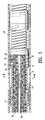
- FIG. 2is a transverse cross-sectional view of the EP device shown in FIG. 1 , taken along the lines 2 — 2 .
- FIG. 3is an elevational view, partially in section, of an EP device assembly embodying features of the invention, illustrating an EP device in a low profile configuration within a guiding catheter.
- FIG. 4is an enlarged longitudinal cross-sectional view of the EP device assembly shown in FIG. 3 taken along the lines 4 — 4 , illustrating the EP device distal tip within the guiding catheter.
- FIG. 5is an enlarged longitudinal cross-sectional view of the EP device assembly shown in FIG. 3 taken along the lines 5 — 5 , illustrating a portion of the EP device distal shaft section within the guiding catheter.
- FIG. 6is a transverse cross sectional view of the EP device assembly shown in FIG. 5 , taken along lines 6 — 6 .
- FIG. 7is a transverse cross sectional view of an alternative embodiment of an EP device assembly embodying features of the invention, having a core wire slidably disposed in a lumen in the device shaft.
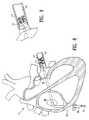
- FIG. 8is an elevational view, partially in section, of a patient's heart and an EP device assembly embodying features of the invention, with the distal end of the EP device transeptally positioned within a pulmonary vein.
- FIG. 9is an elevational view, partially in section, of the EP device assembly of FIG. 8 , with the turns of the helically shaped distal shaft section moved closer together in a stacked configuration.
- FIG. 10is an elevational view of an alternative embodiment of an EP device embodying features of the invention comprising a distal shaft section having a proximal portion with a helical shape and a distal portion with a noncoiled shape with a pair or sensing and/or pacing electrodes on the distal portion.
- FIG. 11is a longitudinal cross sectional view of the distal end of the EP device of FIG. 10 , taken within circle 11 .
- FIG. 12is an elevational view, partially in section, of the EP device of FIG. 10 , positioned in contact with a wall defining a pulmonary vein ostium, with the turns of the helically shaped distal shaft section moved closer together in a stacked configuration.
- FIG. 13is an elevational view of an alternative embodiment of an EP device embodying features of the invention comprising a distal shaft section having a proximal portion with a helical shape with one and one quarter turns, and a distal portion with a noncoiled shape.
- FIG. 1illustrates one embodiment of the EP device 10 of the invention, generally comprising an elongated shaft 11 having a proximal shaft section 12 , a helically shaped distal shaft section 13 , and a plurality of electrodes 14 on the distal shaft section 13 .
- An electrical connector 15 and an adapter 16are on the proximal end of the device.
- FIG. 2illustrates a transverse cross section of the distal end of the device 10 shown in FIG. 1 , taken along lines 2 — 2 .
- FIG. 3illustrates the EP device 10 within a guiding catheter 20 for introduction and advancement within the patient.
- the guiding cathetergenerally comprises an elongated shaft 21 having a proximal end 22 , a distal end 23 , a port 24 in a proximal shaft section, a port 25 in a distal shaft section, and a lumen 26 extending within the shaft to the port in the distal shaft section.
- the helically shaped distal shaft section of the EP device 10is reversibly deformed from the helical configuration to a low profile configuration within the lumen 26 of the guiding catheter.
- FIG. 3illustrates the EP device 10 within a guiding catheter 20 for introduction and advancement within the patient.
- the guiding cathetergenerally comprises an elongated shaft 21 having a proximal end 22 , a distal end 23 , a port 24 in a proximal shaft section, a port 25 in a distal shaft section, and a lumen 26 extending within the shaft to the port in
- the radial force of the guiding catheter 20 against the devicereversibly straightens the helically shaped distal section to form a straight configuration.
- the helically shaped distal shaft section 13is preferably self expanding, so that the EP device 10 can be advanced out the distal end of the guiding catheter 20 , or the guiding catheter 20 proximally retracted, causing the distal shaft section of the EP device to return to the helically shaped configuration illustrated in FIG. 1 .
- the helically shaped distal shaft sectionreversibly collapses to a helical shape with turns having a smaller outer diameter when the distal shaft section is within the guiding catheter lumen 26 .
- the EP device 10includes a core member 17 having a helically shaped distal section, disposed within the shaft 11 .
- the shaft 11comprises a tubular member 18 disposed about the core member 17 .
- the core member 17extends within the tubular member to the distal end of the device, and the tubular member 18 is helically shaped by the core member therein.
- FIG. 6illustrates a transverse cross section of the EP device shown in FIG. 5 , taken along lines 6 — 6 .
- the core member 17is preferably formed of a superelastic material, such as a NiTi alloy, or stainless steel, and has a maximum diameter of about 0.01 inch (0.25 mm) to about 0.018 inch (0.46 mm).
- the core member 17and preferably a distal section thereof, may be tapered as shown in FIG. 4 , or optionally flattened.
- the core memberhas an insulating coating 30 , such as a polyester or polyimide coating.
- the coating 30is preferably about 0.0005 inch (0.0127 mm) thick. In the embodiment illustrated in FIG. 4 , coating 30 extends distally to a point distal to the shaft 11 distal end and proximal to the distal end of core member 17 .
- the coating 30 on the core member 17contacts an inner surface of the tubular member 18 .
- the core member 17is secured to the tubular member 18 by applying heat to the device to melt and fuse the tubular member to the core member coating.
- suitable means of securing the core member within the tubular membermay be used, such as an adhesive (not shown) between the core member and the tubular member.
- the core member 17is slidably disposed within and removable from a lumen 19 of the tubular member.
- a flexible coiled tip 27is provided on the distal end of the EP device 10 .
- the tip 27has a closed distal end, and includes a flexible coil 28 extending beyond the distal end of the shaft 11 enclosed within a soft coating 29 preferably formed of a polymeric material.
- the tip 27has an open center region for increased flexibility.
- a presently preferred polymeric material for the tip 27is a fluoropolymer such as THV available from 3M.
- the core member 17is secured to the distal end of the coil 28 , by suitable material such as gold-tin solder.
- the coil 28may be omitted, and the distal end of the EP device preferably provided with a soft tip to minimize traumatic engagement with a blood vessel wall.
- the electrodes 14comprise helical coils which are electrically connected to insulated electrical conductors 31 .
- the EP device 10 shaftincludes thermocouples 32 , connected to temperature sensor electrical conductors 33 and 34 (i.e., thermocouple wires). Thermocouples are preferably located between adjacent electrodes on an outer surface of the shaft 11 , although they may alternatively be at other locations on the EP device as is conventionally known.
- a conducting member 35such as a gold band, covers the thermocouples, and a polymeric jacket 36 , preferably formed from THV, covers the conducting member 35 and insulates the thermocouple 32 from noise (e.g.
- the electrical conductors 31 and thermocouple wires 33 , 34are braided within the tubular member 18 .
- the electrical conductors 31 and thermocouple wires 33 , 34may have a variety of suitable configurations, including braided or wound configurations different from that shown in FIG. 5 or a nonbraided configuration.
- the individually insulated electrical conductorsmay be within the tubular member lumen 19 or at least in part within an outer jacket of the core member in the embodiment in which the core member is secured to the tubular member.
- the proximal ends of the electrical conductors 31 and thermocouple wires 33 , 34are electrically connected to individual pins of multi-pin connector 15 ( FIG. 1 ) on the proximal end of the shaft.
- FIG. 8illustrates an assembly in a patient's heart 40 , with the EP device 10 in a pulmonary vein 41 .
- the device 10is introduced into the patient's vascular system, e.g. the femoral vein, percutaneously or by way of a cut-down, within the guiding catheter 20 .
- the assemblyis preferably advanced into the right atrium 42 from the inferior vena cava 43 , and positioned in the left atrium 44 traseptally, as illustrated in FIG. 8 .
- the EP device 10 distal sectionextends out of the port in the distal end of the guiding catheter, so that the helically shaped distal shaft section of the device is positioned within the pulmonary vein 41 of the heart.
- the pulmonary vein 41is mapped using electrodes on the device 10 , and if a pulmonary vein potential is detected, the electrodes on the distal shaft section are used to form a lesion(s) extending at least in part around the wall defining the pulmonary vein lumen or in the left atrium just outside a pulmonary vein ostium.
- the position of the lesionis preferably chosen to interrupt the conduction path to the atrium. Alternatively, the lesion may be located to ablate the actual focal origin in the pulmonary vein.
- RF currentis delivered to one or two electrodes to perform a first ablation and then to adjacent electrodes, one or two electrodes at a time, until an ablation of desired length is obtained in the body lumen.
- the temperature sensorscan be used to detect the temperature of the heart wall between the adjacent electrodes, to control the high frequency energy and determine when the lesions formed by adjacent electrodes overlap to form continuous lesions on the wall defining the body lumen. Additionally, feedback of the temperature data can be used to modulate the power and prevent thrombus in the preferred use, and cooling fluid can also be used.
- the electrodes 14can be employed to detect electrical activity to ensure that the ablation has been effective in terminating the fibrillation or flutter.
- the procedureis performed for the left and right, superior and inferior pulmonary veins.
- the EP device of the inventioncan be used to form a helical lesion, a closed circular lesion, or a curvilinear segmental (i.e., discontinuous) lesion.
- a helical lesion on the body lumen wallcan be formed by delivering RF energy to the electrodes which as illustrated are contacting the pulmonary vein wall in a helical array.
- the helical lesionis formed to extend continuously along the body lumen wall, wherein the individual lesions formed by the longitudinally adjacent electrodes on the shaft overlap to produce one continuous lesion.
- the helical lesioncomprises a spiral having a distal end, and a proximal end longitudinally spaced from the distal end of the spiral.
- the lesion formedextends in a closed circle around the body lumen wall, i.e., a lesion having ends that close together to form a circle.
- a closed circle lesioncan be formed by displacing the device distal section to change the electrode position on the body lumen wall after an initial lesion is formed.
- a helically shaped lesionis first formed on the body lumen wall, and then the helically shaped distal shaft section of the EP device is rotated or longitudinally displaced proximally or distally, and a second lesion which overlaps with the first lesion is formed, to thereby form at least one closed circular lesion.
- the helically shaped distal shaft section of the EP devicecan be provided with closely spaced, stacked adjacent turns which facilitate the formation of a closed circle lesion.
- the spacing between adjacent turns of the helically shaped distal shaft sectioncan be changed by the physician during deployment of the EP device within the body lumen.
- the distal extremity of the EP deviceis displaced out of the distal end of the guiding catheter so that it is placed in contact with the body lumen wall.
- the guiding catheteris displaced proximally, while a proximal portion of the EP device is displaced proximally to stretch the turns of the helically shaped distal shaft section apart, so that the portion of the EP device distal shaft section that is still inside the guiding catheter is deployed therefrom with the spacing between the turns increased.
- the spacing between the turnsmay be decreased by retracting the guiding catheter proximally while a proximal portion of the device is displaced distally, to stack the turns of the helically shaped distal shaft section together.
- FIG. 10illustrates an alternative embodiment of an EP device 110 which embodies features of the invention, generally comprising an elongated shaft 111 having a proximal shaft section 112 , a distal shaft section 113 , and a plurality of electrodes 114 on the distal shaft section 113 .
- An electrical connector 115is on the proximal end of the device 110 .
- the distal shaft section 113comprises a proximal portion 116 with a helical shape having one or more turns, and a distal portion 117 extending from the proximal portion with a noncoiled shape.
- FIG. 10illustrates an alternative embodiment of an EP device 110 which embodies features of the invention, generally comprising an elongated shaft 111 having a proximal shaft section 112 , a distal shaft section 113 , and a plurality of electrodes 114 on the distal shaft section 113 .
- An electrical connector 115is on the proximal end of the device 110 .
- the noncoiled distal portion 117has a straight shape with an outer surface aligned or parallel with an outer surface of the proximal shaft section 112 . As illustrated in FIG. 10 , the noncoiled distal portion 117 has a width about equal to or less than the width of the proximal shaft section 112 . Thus, the noncoiled distal portion 117 does not have the enlarged outer diameter formed by the turns of the helically shaped proximal portion 116 .
- the electrodes 114 on the helically shaped proximal portionpreferably comprise coiled electrodes, and temperature sensors 118 are located between the coiled electrodes 114 , preferably on an outer surface of the shaft, as discussed above in relation to the embodiment of FIG. 1 .
- each electrode 114has a length of about 3 to about 6 mm. Although 5 electrodes 114 are illustrated in FIG. 10 , the number of electrodes 114 may vary, and in a presently preferred embodiment, about 8 electrodes are provided on EP device 110 .
- a pair of sensing electrodes 119 for mapping and/or pacingare on the distal portion 117 of the distal shaft section. In an alternative embodiment (not shown) at least a second pair of sensing and pacing and pacing electrodes 119 may be provided on the shaft proximal to the helically shaped proximal portion 116 .
- the sensing and pacing electrodesare preferably spaced away from the helically coiled section 116 , and in one embodiment are about 1 to about 3 cm, preferably about 1.5 to about 2 cm from the helically coiled section.
- the electrodes 114 on the helically shaped portion 116are configured for unipolar use during ablation, and bipolar use during sensing.
- the distal sensing and pacing electrodes 119are configured for use a bipolar electrodes during sensing and pacing.
- a flexible coiled tip 120is secured to the distal end of the distal portion 117 , to facilitate guiding the EP device to a desired location within the patient.
- the tip coil 120is about 1 to about 3 cm, most preferably about 2 cm in length, and is formed of a radiopaque metal such as platinum.
- turns of the helical proximal section 116are illustrated in a relaxed configuration in FIG. 10 . However, the turns of the helical proximal section 116 can be moved closer together or further apart within the patient by urging the proximal end of the catheter distally or proximally, respectively, with the distal end of the catheter in a stabilized position within the patient and as discussed above in relation to the embodiment of FIG. 1 .
- Each electrode 114is spaced apart from one or more adjacent electrodes 114 on the shaft 111 , i.e., the electrodes 114 extend discontinuously along the shaft.
- the lesion(s) formed by electrodes 114can be discontinuous or alternatively, can be joined together and thus continuous.
- the helical proximal portion 116forms one full 360° loop and half of a second loop. In a presently preferred embodiment, about one full 360° loop is provided, although the number of loops may vary. Because the proximal portion 116 is helical, a proximal section of the 360° loop is longitudinally spaced apart from the distal section thereof which completes the circumference of the loop in the relaxed configuration illustrated in FIG. 10 . Consequently, the helical proximal portion forms at least one open or helical 360° loop in the relaxed configuration, and the electrodes 114 thereon form an open or helical 360°, discontinuous loop.
- the circumference of one 360° loop of the helically proximal portion 116varies depending on the desired use of the EP device. In a presently preferred embodiment, the circumference of one 360° loop is about 15 mm to about 40 mm, preferably about 15 mm to about 30 mm. Depending on the circumference of the loop and the number and length of the electrodes 114 , the electrodes 114 may or may not extend the length of one or more 360° loops.
- the electrodes 114extend along the length of at least one 360° loop of the helical proximal portion 116 , so that the electrodes can be used to form a lesion which extends in a continuous 360° loop, or a discontinuous, partial segment of a 360° loop.
- the helical proximal portion 116has a partial loop of less than 360° (not shown), or the electrode number or length is sufficiently small such that the electrodes extend along a length of a partial loop of less than 360° on the helical proximal portion.
- the circumference of the helical sectioni.e., the length of the helical section if it was stretched out to a straight, nonhelical shape, is about 5 to about 40 mm, preferably about 5 to about 20 mm.
- FIG. 11illustrates an enlarged, longitudinal cross sectional view of the distal end of the device 110 , taken within circle 11 .
- the shaft 111comprises a tubular member 121 , having braided electrical conductors 122 in the wall of the tubular member 121 , and having a core member 123 in a lumen of the tubular member 121 .
- the core member 123is secured to the flexible coiled tip 120 .
- An outer layer 124 on an outer surface of the tubular member 121overlaps the ends of the sensing and pacing electrodes 119 .
- FIG. 12illustrates the device 110 with the helically coiled proximal portion 116 of the distal shaft section 113 in position at the ostium 46 of a pulmonary artery which forms the junction between the pulmonary artery and the right atrium of the patient's heart.
- the turns of the helically shaped proximal portion 116are in a stacked configuration after having been moved closer together than the natural relaxed spacing shown in FIG. 10 , by distally forcing the catheter against the wall defining the ostium of the pulmonary artery.
- the electrodes 114extend discontinuously, completely around the ostium.
- High frequency energyis delivered to one or more of the electrodes 114 to form a lesion extending at least in part around the ostium.
- the lesioncan be caused to be a continuous or a discontinuous circular lesion depending on the energy level and the length of time of the ablation, and by rotating the catheter one or more times between delivery of ablation energy to electrodes 114 .
- the distal portion 117 of the distal shaft sectionis positioned within the pulmonary vein 41 , to allow for mapping and/or pacing from within the pulmonary vein.
- the sensing electrodesallow for sensing electrical activity before and after the ablation energy is delivered to electrodes 114 , to determine the appropriate location of the device, and whether the lesions formed therefrom sufficiently treated the atrial arrhythmia.
- the helically shaped proximal portion 116 , and the distal portion 117 of the EP device 110are both positioned within the pulmonary vein 41 , similar to the embodiment illustrated in FIGS. 8 and 9 .
- FIG. 13illustrates an alternative embodiment of an EP device 140 embodying features of the invention, similar to catheter 110 but with helical proximal portion 116 forming one full 360° loop and one quarter of a second loop, and with no electrodes 119 on the noncoiled distal portion 117 .
- a presently preferred method of using EP device 140comprises positioning the helical proximal portion 116 just outside a pulmonary vein at the ostium thereof, with the noncoiled distal portion 117 used as an anchoring section within and in contact with the pulmonary vein.
- the helical proximal portion 116is pushed against the atrial tissue just outside the pulmonary vein ostium, thereby ensuring good contact with atrial tissue for ablation purposes.
- Pushing the shaft distally with the helically shaped section braced against the atrial tissuethus collapses the helix and may advance a distal section of the proximal shaft section proximal to the helically shaped distal portion and through the ostium.
- the electrodes on the helical proximal portion 116are used to map for pulmonary vein potentials and only a discontinuous, segmental lesion, rather than an entire circumference, continuous lesion, is formed by RF ablation, to barricade the pulmonary vein potentials from exiting the pulmonary vein.
- the lesioncomprises one or more closed circles on the endocardium.
- the lesionmay alternatively comprise a discontinuous, partially open circle formed by a plurality of smaller lesions.
- the lesionmay be formed by the helical distal shaft section in the noncollapsed configuration to extend helically along a length of the body lumen, or the lesion may be formed by the helical distal shaft section in the collapsed configuration to extend only around the circumference of the body lumen and not helically along a length of the body lumen.
- the lesion formed with the EP device 10 / 110 / 140 of the present inventionhas a width of about 2 to about 7 mm, preferably about 3 to about 4 mm.
- the circumference of the lesionis about 5 to about 40 mm, preferably about 5 to about 20 mm.
- a lesion extending only circumferentially around the body lumen and not helically along a length of the body lumenhas a length of about the thickness of the EP device shaft.
- a helical lesion extending helically along a length of the body lumenhas a length of about to about 5 mm to about 50 mm, preferably about 5 to about 10 mm.
- the lesionsare formed near the transition zone between the left atrial tissue and the pulmonary vein tissue.
- the EP device 10 / 110 / 140has a total length, including the connector 16 , of about 100 cm to about 200 cm, and preferably between 150 and 180, e.g. about 165 cm.
- the length of the distal shaft section 13 / 113 having electrodes 14 / 114is about 2 cm to about 15 cm, and preferably about 4 to about 8 cm, e.g. about 6 cm.
- the outer diameter of the distal shaft section of the deviceis typically about 1.0 mm (3.0 French) to about 2.0 mm (6.0 French), and preferably about 1.3 mm (4 French) to about 1.7 mm (5 French).
- the maximum outer dimensions of the electrodesare generally about 1.0 mm (3 Fr) to about 1.3 mm (4 Fr), and preferably about 1.22 mm (3.7 Fr).
- the electrode lengthis about 2 mm to about 8 mm, and preferably about 4 to about 7 mm, e.g. about 6 mm.
- the interelectrode spacingis generally about 1 mm to about 3 mm, and preferably about 2 mm. In a presently preferred embodiment, the interelectrode spacing is uniform. However, the electrode spacing may alternatively be nonuniform. In a presently preferred embodiment, about 4 to about 12 individual electrodes are provided on the shaft distal section, however, the device may have larger number of electrodes if the diameter of the distal section is increased to greater than 5 Fr.
- the deviceis used within the patient's vasculature, although it may also be used to create lesions within other body lumens.
- the devicemay be advanced retrogradely through the aorta and left ventricle via a femoral artery access site.
- the guiding cathetermay have a bent or deflectable distal end. Torquing the proximal section 22 of the guiding catheter, which extends out of the patient during the procedure, will cause the distal section thereof to be rotatably displaced within the body lumen and allow the EP device 10 to be properly positioned.
- the EP device componentscan be formed of conventional materials.
- the core member 17 / 123can be formed of a variety of suitable materials including high spring-back metals, or superelastic metals, or shape memory metals, such as ELGILOY available from Carpenter Technology of Pennsylvania, MP35N, available from SPS Technologies, high tensile strength steel including 304 vacuum-melted steel, and titanium alloys including Ti-GAI-4V, C p Titanium, and NiTi.
- the electrical connector 15 on the proximal end of the devicemay be a commercially available electrical connector such as Part No. PAB-M08-GLA39J or PAB-M08-TLA39J for an eight pin connector or Part No. PAB-M08-GLA39A for a connector with a greater number of pins, e.g. 9–16.
- the above connectorsare available from Lemo USA, Inc. in Santa Rosa, Calif.
- Suitable connectors for accessory cables connectable to the above connectorsinclude PRB-M08-GLL65J for eight pin connectors and PRB-M08-GII65A for connectors with more than eight pins. The latter connectors are also available from the same source.
Landscapes
- Health & Medical Sciences (AREA)
- Surgery (AREA)
- Life Sciences & Earth Sciences (AREA)
- Engineering & Computer Science (AREA)
- Heart & Thoracic Surgery (AREA)
- Animal Behavior & Ethology (AREA)
- Otolaryngology (AREA)
- Plasma & Fusion (AREA)
- Physics & Mathematics (AREA)
- Biomedical Technology (AREA)
- Cardiology (AREA)
- Medical Informatics (AREA)
- Molecular Biology (AREA)
- Nuclear Medicine, Radiotherapy & Molecular Imaging (AREA)
- General Health & Medical Sciences (AREA)
- Public Health (AREA)
- Veterinary Medicine (AREA)
- Surgical Instruments (AREA)
- Measurement And Recording Of Electrical Phenomena And Electrical Characteristics Of The Living Body (AREA)
- Pharmaceuticals Containing Other Organic And Inorganic Compounds (AREA)
- Materials For Medical Uses (AREA)
- Electrotherapy Devices (AREA)
Abstract
Description
Claims (26)
Priority Applications (12)
| Application Number | Priority Date | Filing Date | Title |
|---|---|---|---|
| US09/847,181US6972016B2 (en) | 2001-05-01 | 2001-05-01 | Helically shaped electrophysiology catheter |
| JP2002584808AJP2005512609A (en) | 2001-05-01 | 2002-04-29 | Spiral electrophysiology catheter |
| EP02734096AEP1383437B1 (en) | 2001-05-01 | 2002-04-29 | Helically shaped electrophysiology catheter |
| AT02734096TATE347325T1 (en) | 2001-05-01 | 2002-04-29 | SPIRAL-SHAPED CATHETER FOR ELECTROPHISIOLOGICAL USE |
| AU2002305285AAU2002305285A2 (en) | 2001-05-01 | 2002-04-29 | Helically shaped electrophysiology catheter |
| CNB028114191ACN1279876C (en) | 2001-05-01 | 2002-04-29 | spiral electrophysiology catheter |
| DE60216578TDE60216578T2 (en) | 2001-05-01 | 2002-04-29 | Spiral catheter for electrophysiological use |
| EP06018786AEP1733689A1 (en) | 2001-05-01 | 2002-04-29 | Electrophysiology device |
| PCT/US2002/013604WO2002087453A1 (en) | 2001-05-01 | 2002-04-29 | Helically shaped electrophysiology catheter |
| CA002446061ACA2446061A1 (en) | 2001-05-01 | 2002-04-29 | Helically shaped electrophysiology catheter |
| CNB2006101123428ACN100563594C (en) | 2001-05-01 | 2002-04-29 | Electrophysiology device |
| US10/909,668US20050015084A1 (en) | 2001-05-01 | 2004-08-02 | Helically shaped electrophysiology catheter |
Applications Claiming Priority (1)
| Application Number | Priority Date | Filing Date | Title |
|---|---|---|---|
| US09/847,181US6972016B2 (en) | 2001-05-01 | 2001-05-01 | Helically shaped electrophysiology catheter |
Related Child Applications (1)
| Application Number | Title | Priority Date | Filing Date |
|---|---|---|---|
| US10/909,668ContinuationUS20050015084A1 (en) | 2001-05-01 | 2004-08-02 | Helically shaped electrophysiology catheter |
Publications (2)
| Publication Number | Publication Date |
|---|---|
| US20020165532A1 US20020165532A1 (en) | 2002-11-07 |
| US6972016B2true US6972016B2 (en) | 2005-12-06 |
Family
ID=25299993
Family Applications (2)
| Application Number | Title | Priority Date | Filing Date |
|---|---|---|---|
| US09/847,181Expired - LifetimeUS6972016B2 (en) | 2001-05-01 | 2001-05-01 | Helically shaped electrophysiology catheter |
| US10/909,668AbandonedUS20050015084A1 (en) | 2001-05-01 | 2004-08-02 | Helically shaped electrophysiology catheter |
Family Applications After (1)
| Application Number | Title | Priority Date | Filing Date |
|---|---|---|---|
| US10/909,668AbandonedUS20050015084A1 (en) | 2001-05-01 | 2004-08-02 | Helically shaped electrophysiology catheter |
Country Status (9)
| Country | Link |
|---|---|
| US (2) | US6972016B2 (en) |
| EP (2) | EP1733689A1 (en) |
| JP (1) | JP2005512609A (en) |
| CN (2) | CN100563594C (en) |
| AT (1) | ATE347325T1 (en) |
| AU (1) | AU2002305285A2 (en) |
| CA (1) | CA2446061A1 (en) |
| DE (1) | DE60216578T2 (en) |
| WO (1) | WO2002087453A1 (en) |
Cited By (86)
| Publication number | Priority date | Publication date | Assignee | Title |
|---|---|---|---|---|
| US20060089634A1 (en)* | 2002-05-13 | 2006-04-27 | Anderson Neil L | Ablation catheter |
| US20070083194A1 (en)* | 2005-06-20 | 2007-04-12 | Kunis Christopher G | Ablation catheter |
| US20070083196A1 (en)* | 2005-10-11 | 2007-04-12 | Evanston Northwestern Healthcare Research Institute | Surgical instrument and method for tissue resection and dissection |
| US20070135875A1 (en)* | 2002-04-08 | 2007-06-14 | Ardian, Inc. | Methods and apparatus for thermally-induced renal neuromodulation |
| US20070255364A1 (en)* | 2006-04-27 | 2007-11-01 | Medtronic, Inc. | Implantable medical electrical stimulation lead fixation method and apparatus |
| US7429261B2 (en) | 2004-11-24 | 2008-09-30 | Ablation Frontiers, Inc. | Atrial ablation catheter and method of use |
| US7467015B2 (en) | 2004-04-29 | 2008-12-16 | Neuwave Medical, Inc. | Segmented catheter for tissue ablation |
| US7468062B2 (en) | 2004-11-24 | 2008-12-23 | Ablation Frontiers, Inc. | Atrial ablation catheter adapted for treatment of septal wall arrhythmogenic foci and method of use |
| US7676275B1 (en)* | 2005-05-02 | 2010-03-09 | Pacesetter, Inc. | Endovascular lead for chronic nerve stimulation |
| US20100168737A1 (en)* | 2008-12-30 | 2010-07-01 | Debby Esther Grunewald | Catheter with multiple electrode assemblies for use at or near tubular regions of the heart |
| US20100204691A1 (en)* | 2009-02-11 | 2010-08-12 | Bencini Robert F | Insulated ablation catheter devices and methods of use |
| US7813805B1 (en) | 2006-01-11 | 2010-10-12 | Pacesetter, Inc. | Subcardiac threshold vagal nerve stimulation |
| US7857808B2 (en) | 2002-10-25 | 2010-12-28 | The Regents Of The University Of Michigan | Ablation catheters |
| US7869869B1 (en) | 2006-01-11 | 2011-01-11 | Pacesetter, Inc. | Subcardiac threshold vagal nerve stimulation |
| US20110160717A1 (en)* | 2006-07-14 | 2011-06-30 | Neuwave Medical, Inc. | Energy delivery systems and uses thereof |
| US8353907B2 (en) | 2007-12-21 | 2013-01-15 | Atricure, Inc. | Ablation device with internally cooled electrodes |
| US8486063B2 (en) | 2004-10-14 | 2013-07-16 | Medtronic Ablation Frontiers Llc | Ablation catheter |
| US8617152B2 (en) | 2004-11-15 | 2013-12-31 | Medtronic Ablation Frontiers Llc | Ablation system with feedback |
| US8641704B2 (en) | 2007-05-11 | 2014-02-04 | Medtronic Ablation Frontiers Llc | Ablation therapy system and method for treating continuous atrial fibrillation |
| US8657814B2 (en) | 2005-08-22 | 2014-02-25 | Medtronic Ablation Frontiers Llc | User interface for tissue ablation system |
| US8672932B2 (en) | 2006-03-24 | 2014-03-18 | Neuwave Medical, Inc. | Center fed dipole for use with tissue ablation systems, devices and methods |
| US8774913B2 (en) | 2002-04-08 | 2014-07-08 | Medtronic Ardian Luxembourg S.A.R.L. | Methods and apparatus for intravasculary-induced neuromodulation |
| US8834461B2 (en) | 2005-07-11 | 2014-09-16 | Medtronic Ablation Frontiers Llc | Low power tissue ablation system |
| US8834464B2 (en) | 1999-04-05 | 2014-09-16 | Mark T. Stewart | Ablation catheters and associated systems and methods |
| US8888773B2 (en) | 2012-05-11 | 2014-11-18 | Medtronic Ardian Luxembourg S.A.R.L. | Multi-electrode catheter assemblies for renal neuromodulation and associated systems and methods |
| US8934978B2 (en) | 2002-04-08 | 2015-01-13 | Medtronic Ardian Luxembourg S.A.R.L. | Methods and apparatus for renal neuromodulation |
| US8956352B2 (en) | 2010-10-25 | 2015-02-17 | Medtronic Ardian Luxembourg S.A.R.L. | Catheter apparatuses having multi-electrode arrays for renal neuromodulation and associated systems and methods |
| US8998892B2 (en) | 2007-12-21 | 2015-04-07 | Atricure, Inc. | Ablation device with cooled electrodes and methods of use |
| US9095321B2 (en) | 2012-11-21 | 2015-08-04 | Medtronic Ardian Luxembourg S.A.R.L. | Cryotherapeutic devices having integral multi-helical balloons and methods of making the same |
| US9119649B2 (en) | 2009-07-28 | 2015-09-01 | Neuwave Medical, Inc. | Energy delivery systems and uses thereof |
| US9179974B2 (en) | 2013-03-15 | 2015-11-10 | Medtronic Ardian Luxembourg S.A.R.L. | Helical push wire electrode |
| US9192438B2 (en) | 2011-12-21 | 2015-11-24 | Neuwave Medical, Inc. | Energy delivery systems and uses thereof |
| US9468407B2 (en) | 2014-05-30 | 2016-10-18 | Biosense Webster (Israel) Ltd. | Catheter with distal section having side-by-side loops |
| US9707035B2 (en) | 2002-04-08 | 2017-07-18 | Medtronic Ardian Luxembourg S.A.R.L. | Methods for catheter-based renal neuromodulation |
| US9724170B2 (en) | 2012-08-09 | 2017-08-08 | University Of Iowa Research Foundation | Catheters, catheter systems, and methods for puncturing through a tissue structure and ablating a tissue region |
| US9788893B2 (en) | 2014-11-20 | 2017-10-17 | Biosense Webster (Israel) Ltd. | Catheter with soft distal tip for mapping and ablating tubular region |
| US9861440B2 (en) | 2010-05-03 | 2018-01-09 | Neuwave Medical, Inc. | Energy delivery systems and uses thereof |
| US9861438B2 (en) | 2009-12-11 | 2018-01-09 | Biosense Webster (Israel), Ltd. | Pre-formed curved ablation catheter |
| US9987081B1 (en) | 2017-04-27 | 2018-06-05 | Iowa Approach, Inc. | Systems, devices, and methods for signal generation |
| US9999461B2 (en) | 2011-12-09 | 2018-06-19 | Metavention, Inc. | Therapeutic denervation of nerves surrounding a hepatic vessel |
| US9999465B2 (en) | 2014-10-14 | 2018-06-19 | Iowa Approach, Inc. | Method and apparatus for rapid and safe pulmonary vein cardiac ablation |
| US10105180B2 (en) | 2002-04-08 | 2018-10-23 | Medtronic Ardian Luxembourg S.A.R.L. | Methods and apparatus for intravascularly-induced neuromodulation |
| US10130423B1 (en) | 2017-07-06 | 2018-11-20 | Farapulse, Inc. | Systems, devices, and methods for focal ablation |
| US10172673B2 (en) | 2016-01-05 | 2019-01-08 | Farapulse, Inc. | Systems devices, and methods for delivery of pulsed electric field ablative energy to endocardial tissue |
| US10322286B2 (en) | 2016-01-05 | 2019-06-18 | Farapulse, Inc. | Systems, apparatuses and methods for delivery of ablative energy to tissue |
| US10342614B2 (en) | 2004-04-29 | 2019-07-09 | Wisconsin Alumni Research Foundation | Triaxial antenna for microwave tissue ablation |
| US10363092B2 (en) | 2006-03-24 | 2019-07-30 | Neuwave Medical, Inc. | Transmission line with heat transfer ability |
| US10420606B2 (en) | 2002-04-08 | 2019-09-24 | Medtronic Ardian Luxembourg S.A.R.L. | Methods and apparatus for performing a non-continuous circumferential treatment of a body lumen |
| US10433906B2 (en) | 2014-06-12 | 2019-10-08 | Farapulse, Inc. | Method and apparatus for rapid and selective transurethral tissue ablation |
| US10507302B2 (en) | 2016-06-16 | 2019-12-17 | Farapulse, Inc. | Systems, apparatuses, and methods for guide wire delivery |
| US10512505B2 (en) | 2018-05-07 | 2019-12-24 | Farapulse, Inc. | Systems, apparatuses and methods for delivery of ablative energy to tissue |
| US10517672B2 (en) | 2014-01-06 | 2019-12-31 | Farapulse, Inc. | Apparatus and methods for renal denervation ablation |
| US10524859B2 (en) | 2016-06-07 | 2020-01-07 | Metavention, Inc. | Therapeutic tissue modulation devices and methods |
| US10531917B2 (en) | 2016-04-15 | 2020-01-14 | Neuwave Medical, Inc. | Systems and methods for energy delivery |
| US10617867B2 (en) | 2017-04-28 | 2020-04-14 | Farapulse, Inc. | Systems, devices, and methods for delivery of pulsed electric field ablative energy to esophageal tissue |
| US10624693B2 (en) | 2014-06-12 | 2020-04-21 | Farapulse, Inc. | Method and apparatus for rapid and selective tissue ablation with cooling |
| US10625080B1 (en) | 2019-09-17 | 2020-04-21 | Farapulse, Inc. | Systems, apparatuses, and methods for detecting ectopic electrocardiogram signals during pulsed electric field ablation |
| US10660702B2 (en) | 2016-01-05 | 2020-05-26 | Farapulse, Inc. | Systems, devices, and methods for focal ablation |
| US10687892B2 (en) | 2018-09-20 | 2020-06-23 | Farapulse, Inc. | Systems, apparatuses, and methods for delivery of pulsed electric field ablative energy to endocardial tissue |
| US10709490B2 (en) | 2014-05-07 | 2020-07-14 | Medtronic Ardian Luxembourg S.A.R.L. | Catheter assemblies comprising a direct heating element for renal neuromodulation and associated systems and methods |
| US10736690B2 (en) | 2014-04-24 | 2020-08-11 | Medtronic Ardian Luxembourg S.A.R.L. | Neuromodulation catheters and associated systems and methods |
| US10842572B1 (en) | 2019-11-25 | 2020-11-24 | Farapulse, Inc. | Methods, systems, and apparatuses for tracking ablation devices and generating lesion lines |
| US10893905B2 (en) | 2017-09-12 | 2021-01-19 | Farapulse, Inc. | Systems, apparatuses, and methods for ventricular focal ablation |
| US10952792B2 (en) | 2015-10-26 | 2021-03-23 | Neuwave Medical, Inc. | Energy delivery systems and uses thereof |
| US11020180B2 (en) | 2018-05-07 | 2021-06-01 | Farapulse, Inc. | Epicardial ablation catheter |
| US11033236B2 (en) | 2018-05-07 | 2021-06-15 | Farapulse, Inc. | Systems, apparatuses, and methods for filtering high voltage noise induced by pulsed electric field ablation |
| US11065047B2 (en) | 2019-11-20 | 2021-07-20 | Farapulse, Inc. | Systems, apparatuses, and methods for protecting electronic components from high power noise induced by high voltage pulses |
| US11213678B2 (en) | 2013-09-09 | 2022-01-04 | Medtronic Ardian Luxembourg S.A.R.L. | Method of manufacturing a medical device for neuromodulation |
| US11259869B2 (en) | 2014-05-07 | 2022-03-01 | Farapulse, Inc. | Methods and apparatus for selective tissue ablation |
| US11389235B2 (en) | 2006-07-14 | 2022-07-19 | Neuwave Medical, Inc. | Energy delivery systems and uses thereof |
| US11497541B2 (en) | 2019-11-20 | 2022-11-15 | Boston Scientific Scimed, Inc. | Systems, apparatuses, and methods for protecting electronic components from high power noise induced by high voltage pulses |
| US11589768B2 (en) | 2014-10-13 | 2023-02-28 | Boston Scientific Scimed Inc. | Tissue diagnosis and treatment using mini-electrodes |
| US11672596B2 (en) | 2018-02-26 | 2023-06-13 | Neuwave Medical, Inc. | Energy delivery devices with flexible and adjustable tips |
| US11832879B2 (en) | 2019-03-08 | 2023-12-05 | Neuwave Medical, Inc. | Systems and methods for energy delivery |
| US11832880B2 (en) | 2018-12-13 | 2023-12-05 | Neuwave Medical, Inc. | Energy delivery devices and related systems and methods thereof |
| US11857738B2 (en) | 2019-12-16 | 2024-01-02 | Biosense Webster (Israel) Ltd. | Stabilized coronary sinus catheter handle |
| US12011212B2 (en) | 2013-06-05 | 2024-06-18 | Medtronic Ireland Manufacturing Unlimited Company | Modulation of targeted nerve fibers |
| US12042208B2 (en) | 2018-05-03 | 2024-07-23 | Boston Scientific Scimed, Inc. | Systems, devices, and methods for ablation using surgical clamps |
| US12137968B2 (en) | 2014-05-16 | 2024-11-12 | Boston Scientific Scimed, Inc. | Methods and apparatus for multi-catheter tissue ablation |
| US12144541B2 (en) | 2016-01-05 | 2024-11-19 | Boston Scientific Scimed, Inc. | Systems, apparatuses and methods for delivery of ablative energy to tissue |
| US12268437B2 (en) | 2020-07-24 | 2025-04-08 | Boston Scientific Scimed, Inc. | Electric field application for single shot cardiac ablation by irreversible electroporation |
| US12295637B2 (en) | 2018-02-08 | 2025-05-13 | Boston Scientific Scimed, Inc. | Method and apparatus for controlled delivery of pulsed electric field ablative energy to tissue |
| US12310652B2 (en) | 2020-07-24 | 2025-05-27 | Boston Scientific Scimed, Inc. | Hybrid electroporation ablation catheter |
| US12343071B2 (en) | 2021-01-27 | 2025-07-01 | Boston Scientific Scimed, Inc | Voltage controlled pulse sequences for irreversible electroporation ablations |
| US12349964B2 (en) | 2020-09-30 | 2025-07-08 | Boston Scientific Scimed, Inc. | Pretreatment waveform for irreversible electroporation |
| US12408974B2 (en) | 2014-12-03 | 2025-09-09 | Medtronic Ireland Manufacturing Unlimited Company | Systems and methods for modulating nerves or other tissue |
Families Citing this family (145)
| Publication number | Priority date | Publication date | Assignee | Title |
|---|---|---|---|---|
| US6302875B1 (en) | 1996-10-11 | 2001-10-16 | Transvascular, Inc. | Catheters and related devices for forming passageways between blood vessels or other anatomical structures |
| US7617005B2 (en) | 2002-04-08 | 2009-11-10 | Ardian, Inc. | Methods and apparatus for thermally-induced renal neuromodulation |
| US8175711B2 (en)* | 2002-04-08 | 2012-05-08 | Ardian, Inc. | Methods for treating a condition or disease associated with cardio-renal function |
| US20110207758A1 (en) | 2003-04-08 | 2011-08-25 | Medtronic Vascular, Inc. | Methods for Therapeutic Renal Denervation |
| US9308044B2 (en) | 2002-04-08 | 2016-04-12 | Medtronic Ardian Luxembourg S.A.R.L. | Methods for therapeutic renal neuromodulation |
| US8774922B2 (en) | 2002-04-08 | 2014-07-08 | Medtronic Ardian Luxembourg S.A.R.L. | Catheter apparatuses having expandable balloons for renal neuromodulation and associated systems and methods |
| US7853333B2 (en) | 2002-04-08 | 2010-12-14 | Ardian, Inc. | Methods and apparatus for multi-vessel renal neuromodulation |
| US20080213331A1 (en) | 2002-04-08 | 2008-09-04 | Ardian, Inc. | Methods and devices for renal nerve blocking |
| US9636174B2 (en) | 2002-04-08 | 2017-05-02 | Medtronic Ardian Luxembourg S.A.R.L. | Methods for therapeutic renal neuromodulation |
| US7620451B2 (en)* | 2005-12-29 | 2009-11-17 | Ardian, Inc. | Methods and apparatus for pulsed electric field neuromodulation via an intra-to-extravascular approach |
| US8145316B2 (en) | 2002-04-08 | 2012-03-27 | Ardian, Inc. | Methods and apparatus for renal neuromodulation |
| US8145317B2 (en) | 2002-04-08 | 2012-03-27 | Ardian, Inc. | Methods for renal neuromodulation |
| US8131371B2 (en) | 2002-04-08 | 2012-03-06 | Ardian, Inc. | Methods and apparatus for monopolar renal neuromodulation |
| US7162303B2 (en) | 2002-04-08 | 2007-01-09 | Ardian, Inc. | Renal nerve stimulation method and apparatus for treatment of patients |
| US6978174B2 (en) | 2002-04-08 | 2005-12-20 | Ardian, Inc. | Methods and devices for renal nerve blocking |
| US9308043B2 (en) | 2002-04-08 | 2016-04-12 | Medtronic Ardian Luxembourg S.A.R.L. | Methods for monopolar renal neuromodulation |
| US8150519B2 (en) | 2002-04-08 | 2012-04-03 | Ardian, Inc. | Methods and apparatus for bilateral renal neuromodulation |
| US20070129761A1 (en) | 2002-04-08 | 2007-06-07 | Ardian, Inc. | Methods for treating heart arrhythmia |
| US20040082859A1 (en) | 2002-07-01 | 2004-04-29 | Alan Schaer | Method and apparatus employing ultrasound energy to treat body sphincters |
| EP1542587B1 (en) | 2002-08-24 | 2011-04-27 | St. Jude Medical, Atrial Fibrillation Division, Inc. | Method and apparatus for locating the fossa ovalis and performing transseptal puncture |
| US8361067B2 (en) | 2002-09-30 | 2013-01-29 | Relievant Medsystems, Inc. | Methods of therapeutically heating a vertebral body to treat back pain |
| US20050033137A1 (en)* | 2002-10-25 | 2005-02-10 | The Regents Of The University Of Michigan | Ablation catheters and methods for their use |
| WO2004078065A2 (en) | 2003-03-03 | 2004-09-16 | Sinus Rhythm Technologies, Inc. | Electrical conduction block implant device |
| US7142903B2 (en) | 2003-03-12 | 2006-11-28 | Biosense Webster, Inc. | Catheter with contractable mapping assembly |
| US7569052B2 (en)* | 2003-09-12 | 2009-08-04 | Boston Scientific Scimed, Inc. | Ablation catheter with tissue protecting assembly |
| DE202004021953U1 (en) | 2003-09-12 | 2013-06-19 | Vessix Vascular, Inc. | Selectable eccentric remodeling and / or ablation of atherosclerotic material |
| SE526861C2 (en)* | 2003-11-17 | 2005-11-15 | Syntach Ag | Tissue lesion creation device and a set of devices for the treatment of cardiac arrhythmia disorders |
| US9398967B2 (en) | 2004-03-02 | 2016-07-26 | Syntach Ag | Electrical conduction block implant device |
| JP5219518B2 (en) | 2004-12-09 | 2013-06-26 | ザ ファウンドリー, エルエルシー | Aortic valve repair |
| US20070021743A1 (en)* | 2005-07-22 | 2007-01-25 | Boston Scientific Scimed, Inc. | Compressible/expandable hydrophilic ablation electrode |
| US20070021803A1 (en) | 2005-07-22 | 2007-01-25 | The Foundry Inc. | Systems and methods for neuromodulation for treatment of pain and other disorders associated with nerve conduction |
| US9414883B2 (en) | 2006-06-09 | 2016-08-16 | Boston Scientific Scimed, Inc. | Co-access foam/electrode introducer |
| CN103222894B (en) | 2006-06-28 | 2015-07-01 | 美敦力Af卢森堡公司 | Methods and systems for thermally-induced renal neuromodulation |
| US20080161705A1 (en)* | 2006-12-29 | 2008-07-03 | Podmore Jonathan L | Devices and methods for ablating near AV groove |
| US11395694B2 (en) | 2009-05-07 | 2022-07-26 | St. Jude Medical, Llc | Irrigated ablation catheter with multiple segmented ablation electrodes |
| US10220187B2 (en) | 2010-06-16 | 2019-03-05 | St. Jude Medical, Llc | Ablation catheter having flexible tip with multiple flexible electrode segments |
| ITBA20070049A1 (en)* | 2007-06-14 | 2008-12-15 | Massimo Grimaldi | CATHETERS FOR ABLATION TRANSCATETER BY PERCUTANEOUS ROUTE OF HEART ARITHMIA THROUGH BIPOLAR RADIOFREQUENCY |
| US10028753B2 (en) | 2008-09-26 | 2018-07-24 | Relievant Medsystems, Inc. | Spine treatment kits |
| CA2737374C (en) | 2008-09-26 | 2017-03-28 | Relievant Medsystems, Inc. | Systems and methods for navigating an instrument through bone |
| US11376061B2 (en) | 2008-11-11 | 2022-07-05 | Covidien Lp | Energy delivery device and methods of use |
| US8808345B2 (en) | 2008-12-31 | 2014-08-19 | Medtronic Ardian Luxembourg S.A.R.L. | Handle assemblies for intravascular treatment devices and associated systems and methods |
| US8652129B2 (en) | 2008-12-31 | 2014-02-18 | Medtronic Ardian Luxembourg S.A.R.L. | Apparatus, systems, and methods for achieving intravascular, thermally-induced renal neuromodulation |
| WO2010080886A1 (en) | 2009-01-09 | 2010-07-15 | Recor Medical, Inc. | Methods and apparatus for treatment of mitral valve in insufficiency |
| CN101849825B (en)* | 2009-03-30 | 2014-03-26 | 上海微创医疗器械(集团)有限公司 | Weaving silk strengthening tube and electrophysiology conduit using same |
| JP5272888B2 (en)* | 2009-05-19 | 2013-08-28 | 東レ株式会社 | Ablation catheter system with guide wire and balloon |
| WO2011056684A2 (en)* | 2009-10-27 | 2011-05-12 | Innovative Pulmonary Solutions, Inc. | Delivery devices with coolable energy emitting assemblies |
| ATE548986T1 (en)* | 2009-11-30 | 2012-03-15 | Sorin Crm Sas | CUTLERY FOR DRILLING THE CARDIAC SEPTUM AND IMPLANTING A TRANSSEPTAL PROBE, ESPECIALLY A PROBE FOR DETECTING/STIMULATING A DEPRESSION TO THE LEFT OF THE HEART |
| WO2011091069A1 (en)* | 2010-01-19 | 2011-07-28 | Ardian, Inc. | Methods and apparatus for renal neuromodulation via stereotactic radiotherapy |
| US20110208175A1 (en)* | 2010-02-24 | 2011-08-25 | Medtronic Vascular, Inc. | Methods for Treating Sleep Apnea Via Renal Denervation |
| US8556891B2 (en) | 2010-03-03 | 2013-10-15 | Medtronic Ablation Frontiers Llc | Variable-output radiofrequency ablation power supply |
| US8870863B2 (en) | 2010-04-26 | 2014-10-28 | Medtronic Ardian Luxembourg S.A.R.L. | Catheter apparatuses, systems, and methods for renal neuromodulation |
| EP2563255B1 (en)* | 2010-04-26 | 2017-03-22 | Medtronic Ardian Luxembourg S.à.r.l. | Catheter apparatuses and systems for renal neuromodulation |
| US10413355B2 (en)* | 2010-05-10 | 2019-09-17 | Atricure, Inc. | Vacuum coagulation probes |
| US9408661B2 (en)* | 2010-07-30 | 2016-08-09 | Patrick A. Haverkost | RF electrodes on multiple flexible wires for renal nerve ablation |
| US20120089047A1 (en) | 2010-08-05 | 2012-04-12 | Medtronic Vascular, Inc. | Cryoablation apparatuses, systems, and methods for renal neuromodulation |
| US9084610B2 (en) | 2010-10-21 | 2015-07-21 | Medtronic Ardian Luxembourg S.A.R.L. | Catheter apparatuses, systems, and methods for renal neuromodulation |
| WO2012061150A1 (en) | 2010-10-25 | 2012-05-10 | Medtronic Ardian Luxembourg S.a.r.I. | Microwave catheter apparatuses, systems, and methods for renal neuromodulation |
| TWI513451B (en) | 2010-10-25 | 2015-12-21 | Medtronic Ardian Luxembourg | Devices, systems and methods for evaluation and feedback of neuromodulation treatment |
| US9060754B2 (en) | 2010-10-26 | 2015-06-23 | Medtronic Ardian Luxembourg S.A.R.L. | Neuromodulation cryotherapeutic devices and associated systems and methods |
| US20120158104A1 (en) | 2010-10-26 | 2012-06-21 | Medtronic Ardian Luxembourg S.A.R.L. | Neuromodulation cryotherapeutic devices and associated systems and methods |
| WO2012068268A2 (en) | 2010-11-17 | 2012-05-24 | Medtronic Ardian Luxembourg S.A.R.L. | Therapeutic renal neuromodulation for treating dyspnea and associated systems and methods |
| JP5759615B2 (en) | 2011-04-08 | 2015-08-05 | コヴィディエン リミテッド パートナーシップ | Iontophoretic catheter system and method for renal sympathetic denervation and iontophoretic drug delivery |
| WO2012148969A2 (en) | 2011-04-25 | 2012-11-01 | Brian Kelly | Apparatus and methods related to constrained deployment of cryogenic balloons for limited cryogenic ablation of vessel walls |
| CN102198015B (en)* | 2011-05-03 | 2013-11-06 | 上海微创电生理医疗科技有限公司 | Retractable spiral laminar ring type electrode catheter |
| EP2775899B1 (en) | 2011-11-07 | 2017-08-23 | Medtronic Ardian Luxembourg S.à.r.l. | Endovascular nerve monitoring devices and associated systems |
| US9192766B2 (en) | 2011-12-02 | 2015-11-24 | Medtronic Ardian Luxembourg S.A.R.L. | Renal neuromodulation methods and devices for treatment of polycystic kidney disease |
| CN102488552B (en)* | 2011-12-15 | 2015-04-15 | 四川锦江电子科技有限公司 | Manageable spiral electrophysiology catheter |
| AU2012362524B2 (en) | 2011-12-30 | 2018-12-13 | Relievant Medsystems, Inc. | Systems and methods for treating back pain |
| WO2013134469A1 (en) | 2012-03-07 | 2013-09-12 | Medtronic Ardian Luxembourg Sarl | Selective modulation of renal nerves |
| WO2013134541A2 (en) | 2012-03-08 | 2013-09-12 | Medtronic Ardian Luxembourg Sarl | Gastrointestinal neuromodulation and associated systems and methods |
| AU2013230781B2 (en) | 2012-03-08 | 2015-12-03 | Medtronic Af Luxembourg S.A.R.L. | Ovarian neuromodulation and associated systems and methods |
| WO2013134472A1 (en) | 2012-03-08 | 2013-09-12 | Medtronic Ardian Luxembourg S.A.R.L. | Renal neuromodulation methods and systems for treatment of hyperaldosteronism |
| AU2013230893B2 (en) | 2012-03-08 | 2015-12-03 | Medtronic Af Luxembourg S.A.R.L. | Neuromodulation and associated systems and methods for the management of pain |
| US9597018B2 (en) | 2012-03-08 | 2017-03-21 | Medtronic Ardian Luxembourg S.A.R.L. | Biomarker sampling in the context of neuromodulation devices, systems, and methods |
| AU2013230906A1 (en) | 2012-03-08 | 2014-09-18 | Medtronic Af Luxembourg S.A.R.L. | Neuromodulation and associated systems and methods for the treatment of sexual dysfunction |
| US9241752B2 (en) | 2012-04-27 | 2016-01-26 | Medtronic Ardian Luxembourg S.A.R.L. | Shafts with pressure relief in cryotherapeutic catheters and associated devices, systems, and methods |
| WO2013162721A1 (en) | 2012-04-27 | 2013-10-31 | Medtronic Ardian Luxembourg Sarl | Methods and devices for localized inhibition of inflammation by ablation |
| CN104411263A (en) | 2012-04-27 | 2015-03-11 | 美敦力阿迪安卢森堡有限公司 | Cryotherapeutic devices for renal neuromodulation and associated systems and methods |
| US10258791B2 (en) | 2012-04-27 | 2019-04-16 | Medtronic Ardian Luxembourg S.A.R.L. | Catheter assemblies for neuromodulation proximate a bifurcation of a renal artery and associated systems and methods |
| US9848950B2 (en) | 2012-04-27 | 2017-12-26 | Medtronic Ardian Luxembourg S.A.R.L. | Methods and devices for localized disease treatment by ablation |
| CN102772249B (en)* | 2012-06-19 | 2015-01-21 | 深圳市惠泰医疗器械有限公司 | Radiofrequency ablation electrode catheter of renal artery rail |
| US8951296B2 (en) | 2012-06-29 | 2015-02-10 | Medtronic Ardian Luxembourg S.A.R.L. | Devices and methods for photodynamically modulating neural function in a human |
| US10588691B2 (en) | 2012-09-12 | 2020-03-17 | Relievant Medsystems, Inc. | Radiofrequency ablation of tissue within a vertebral body |
| US8612022B1 (en) | 2012-09-13 | 2013-12-17 | Invatec S.P.A. | Neuromodulation catheters and associated systems and methods |
| CN102940525A (en)* | 2012-10-17 | 2013-02-27 | 上海安通医疗科技有限公司 | Multi-pole helicoidal radiofrequency ablation conduit |
| US20140110296A1 (en) | 2012-10-19 | 2014-04-24 | Medtronic Ardian Luxembourg S.A.R.L. | Packaging for Catheter Treatment Devices and Associated Devices, Systems, and Methods |
| US9044575B2 (en) | 2012-10-22 | 2015-06-02 | Medtronic Adrian Luxembourg S.a.r.l. | Catheters with enhanced flexibility and associated devices, systems, and methods |
| ES2733273T3 (en) | 2012-10-22 | 2019-11-28 | Medtronic Ardian Luxembourg | Catheters with improved flexibility |
| WO2014071161A1 (en) | 2012-11-05 | 2014-05-08 | Relievant Medsystems, Inc. | System and methods for creating curved paths through bone and modulating nerves within the bone |
| US9017317B2 (en) | 2012-12-06 | 2015-04-28 | Medtronic Ardian Luxembourg S.A.R.L. | Refrigerant supply system for cryotherapy including refrigerant recompression and associated devices, systems, and methods |
| CN103860258A (en)* | 2012-12-12 | 2014-06-18 | 北京中孵友信医药科技股份有限公司 | Self-adaptive annular positioning endovascular catheter |
| CN103169537B (en)* | 2013-02-26 | 2015-09-09 | 上海安通医疗科技有限公司 | The netted radio frequency ablation catheter of a kind of multipole |
| EP2968919B1 (en) | 2013-03-15 | 2021-08-25 | Medtronic Ardian Luxembourg S.à.r.l. | Controlled neuromodulation systems |
| US9066726B2 (en) | 2013-03-15 | 2015-06-30 | Medtronic Ardian Luxembourg S.A.R.L. | Multi-electrode apposition judgment using pressure elements |
| CN104127233B (en)* | 2013-05-03 | 2019-02-22 | 上海安通医疗科技有限公司 | It is a kind of for adjust nerve device |
| EP2996754B1 (en) | 2013-05-18 | 2023-04-26 | Medtronic Ardian Luxembourg S.à.r.l. | Neuromodulation catheters with shafts for enhanced flexibility and control and associated devices and systems |
| US9724151B2 (en) | 2013-08-08 | 2017-08-08 | Relievant Medsystems, Inc. | Modulating nerves within bone using bone fasteners |
| US9339332B2 (en) | 2013-08-30 | 2016-05-17 | Medtronic Ardian Luxembourg S.A.R.L. | Neuromodulation catheters with nerve monitoring features for transmitting digital neural signals and associated systems and methods |
| US9326816B2 (en) | 2013-08-30 | 2016-05-03 | Medtronic Ardian Luxembourg S.A.R.L. | Neuromodulation systems having nerve monitoring assemblies and associated devices, systems, and methods |
| US9138578B2 (en) | 2013-09-10 | 2015-09-22 | Medtronic Ardian Luxembourg S.A.R.L. | Endovascular catheters with tuned control members and associated systems and methods |
| US10433902B2 (en) | 2013-10-23 | 2019-10-08 | Medtronic Ardian Luxembourg S.A.R.L. | Current control methods and systems |
| US10105073B2 (en)* | 2013-11-21 | 2018-10-23 | Biosense Webster (Israel) Ltd | Flexible multiple-arm diagnostic catheter |
| CN104688331A (en)* | 2013-12-09 | 2015-06-10 | 上海安通医疗科技有限公司 | Catheter device used for regulating nerves |
| EP4253024B1 (en) | 2014-01-27 | 2025-02-26 | Medtronic Ireland Manufacturing Unlimited Company | Neuromodulation catheters having jacketed neuromodulation elements and related devices |
| US10492842B2 (en) | 2014-03-07 | 2019-12-03 | Medtronic Ardian Luxembourg S.A.R.L. | Monitoring and controlling internally administered cryotherapy |
| US10463424B2 (en) | 2014-03-11 | 2019-11-05 | Medtronic Ardian Luxembourg S.A.R.L. | Catheters with independent radial-expansion members and associated devices, systems, and methods |
| US9579149B2 (en) | 2014-03-13 | 2017-02-28 | Medtronic Ardian Luxembourg S.A.R.L. | Low profile catheter assemblies and associated systems and methods |
| US9980766B1 (en) | 2014-03-28 | 2018-05-29 | Medtronic Ardian Luxembourg S.A.R.L. | Methods and systems for renal neuromodulation |
| US10194979B1 (en) | 2014-03-28 | 2019-02-05 | Medtronic Ardian Luxembourg S.A.R.L. | Methods for catheter-based renal neuromodulation |
| US10194980B1 (en) | 2014-03-28 | 2019-02-05 | Medtronic Ardian Luxembourg S.A.R.L. | Methods for catheter-based renal neuromodulation |
| US10610292B2 (en) | 2014-04-25 | 2020-04-07 | Medtronic Ardian Luxembourg S.A.R.L. | Devices, systems, and methods for monitoring and/or controlling deployment of a neuromodulation element within a body lumen and related technology |
| CN105167840A (en)* | 2014-06-20 | 2015-12-23 | 上海安通医疗科技有限公司 | Multi-electrode renal artery radiofrequency ablation catheter |
| CN105326562A (en)* | 2014-06-24 | 2016-02-17 | 上海安通医疗科技有限公司 | Catheter device for regulating renal nerves |
| CN105361943B (en)* | 2014-08-27 | 2021-04-20 | 上海安通医疗科技有限公司 | Catheter device for regulating nerves |
| US11154712B2 (en) | 2014-08-28 | 2021-10-26 | Medtronic Ardian Luxembourg S.A.R.L. | Methods for assessing efficacy of renal neuromodulation and associated systems and devices |
| WO2016054379A1 (en) | 2014-10-01 | 2016-04-07 | Medtronic Ardian Luxembourg S.A.R.L. | Systems and methods for evaluating neuromodulation therapy via hemodynamic responses |
| CN105534595B (en)* | 2014-10-31 | 2019-02-22 | 四川锦江电子科技有限公司 | A kind of ablating electrode |
| WO2016075536A2 (en) | 2014-11-14 | 2016-05-19 | Medtronic Ardian Luxembourg S.A.R.L. | Catheter apparatuses for modulation of nerves in communication with the pulmonary system and associated systems and methods |
| US10667736B2 (en) | 2014-12-17 | 2020-06-02 | Medtronic Ardian Luxembourg S.A.R.L. | Systems and methods for assessing sympathetic nervous system tone for neuromodulation therapy |
| US10376308B2 (en) | 2015-02-05 | 2019-08-13 | Axon Therapies, Inc. | Devices and methods for treatment of heart failure by splanchnic nerve ablation |
| US10448994B2 (en) | 2016-01-13 | 2019-10-22 | Abbott Cardiovascular Systems Inc. | Method of manufacturing a shaping structure for denervation |
| US10736692B2 (en) | 2016-04-28 | 2020-08-11 | Medtronic Ardian Luxembourg S.A.R.L. | Neuromodulation and associated systems and methods for the treatment of cancer |
| WO2018006384A1 (en)* | 2016-07-07 | 2018-01-11 | 四川锦江电子科技有限公司 | Ablation electrode |
| WO2018023132A1 (en) | 2016-07-29 | 2018-02-01 | Axon Therepies, Inc. | Devices, systems, and methods for treatment of heart failure by splanchnic nerve ablation |
| CN106236246A (en)* | 2016-08-24 | 2016-12-21 | 王卫东 | Ablating device |
| US10231784B2 (en) | 2016-10-28 | 2019-03-19 | Medtronic Ardian Luxembourg S.A.R.L. | Methods and systems for optimizing perivascular neuromodulation therapy using computational fluid dynamics |
| CN106539624B (en)* | 2016-11-23 | 2019-12-03 | 常州朗合医疗器械有限公司 | Medical path air navigation aid, method and system for planning |
| US10646713B2 (en) | 2017-02-22 | 2020-05-12 | Medtronic Ardian Luxembourg S.A.R.L. | Systems, devices, and associated methods for treating patients via renal neuromodulation to reduce a risk of developing cognitive impairment |
| CN107349010A (en)* | 2017-07-07 | 2017-11-17 | 昆山雷盛医疗科技有限公司 | Radio frequency ablation probe and preparation method thereof |
| US10561461B2 (en) | 2017-12-17 | 2020-02-18 | Axon Therapies, Inc. | Methods and devices for endovascular ablation of a splanchnic nerve |
| CN109953814A (en)* | 2017-12-25 | 2019-07-02 | 四川锦江电子科技有限公司 | A kind of combined type ablation sting device |
| US20190195310A1 (en)* | 2017-12-27 | 2019-06-27 | On Top Safety, Inc. | Force damper |
| US12082917B2 (en) | 2018-01-24 | 2024-09-10 | Medtronic Ireland Manufacturing Unlimited Company | Systems, devices, and methods for assessing efficacy of renal neuromodulation therapy |
| CA3089217A1 (en) | 2018-01-26 | 2019-08-01 | Dorin Panescu | Methods and devices for endovascular ablation of a splanchnic nerve |
| CN108457669B (en)* | 2018-04-25 | 2024-04-12 | 南京大学 | A spiral shield tunnel lining segment and its construction method |
| EP3917426B1 (en) | 2019-06-20 | 2023-09-06 | Axon Therapies, Inc. | Devices for endovascular ablation of a splanchnic nerve |
| AU2020346827A1 (en) | 2019-09-12 | 2022-03-31 | Relievant Medsystems, Inc. | Systems and methods for tissue modulation |
| US20210161593A1 (en)* | 2019-12-03 | 2021-06-03 | Biosense Webster (Israel) Ltd. | Pulse Generator for Irreversible Electroporation |
| CN111067617A (en)* | 2019-12-27 | 2020-04-28 | 苏州恒瑞宏远医疗科技有限公司 | Radiofrequency closed catheter and method of making the same |
| US11413090B2 (en)* | 2020-01-17 | 2022-08-16 | Axon Therapies, Inc. | Methods and devices for endovascular ablation of a splanchnic nerve |
| US12082876B1 (en) | 2020-09-28 | 2024-09-10 | Relievant Medsystems, Inc. | Introducer drill |
| EP4268150A4 (en) | 2020-12-22 | 2024-12-18 | Relievant Medsystems, Inc. | PREDICTION OF CANDIDATES FOR SPINAL NEUROMODULATION |
| PL4056135T3 (en) | 2021-03-09 | 2023-10-02 | Circle Safe | Phrenic nerve stimulation |
| US12433668B1 (en) | 2021-11-08 | 2025-10-07 | Relievant Medsystems, Inc. | Impedance stoppage mitigation during radiofrequency tissue ablation procedures |
| CN115804637A (en)* | 2022-11-09 | 2023-03-17 | 杭州矩正医疗科技有限公司 | Vein radio frequency ablation system and processing method |
Citations (5)
| Publication number | Priority date | Publication date | Assignee | Title |
|---|---|---|---|---|
| US20010020174A1 (en)* | 1999-11-22 | 2001-09-06 | Scimed Life Systems, Inc. | Helical and pre-oriented loop structures for supporting diagnostic and therapeutic elements in contact with body tissue |
| US6325797B1 (en)* | 1999-04-05 | 2001-12-04 | Medtronic, Inc. | Ablation catheter and method for isolating a pulmonary vein |
| US20020004631A1 (en)* | 1999-11-22 | 2002-01-10 | Jenkins Thomas R. | Loop structures for supporting diagnostic and therapeutic elements in contact with body tissue |
| US20020062124A1 (en)* | 1999-09-15 | 2002-05-23 | David Keane | Coiled ablation catheter system |
| US6628976B1 (en)* | 2000-01-27 | 2003-09-30 | Biosense Webster, Inc. | Catheter having mapping assembly |
Family Cites Families (30)
| Publication number | Priority date | Publication date | Assignee | Title |
|---|---|---|---|---|
| KR950003135B1 (en)* | 1985-04-03 | 1995-04-01 | 가부시기가이샤 히다찌세이사꾸쇼 | Amplifier and display device |
| DE69019509T2 (en)* | 1990-03-30 | 1996-02-15 | Pacesetter Ab | Device for positioning an electrode. |
| US5231989A (en)* | 1991-02-15 | 1993-08-03 | Raychem Corporation | Steerable cannula |
| US5228442A (en)* | 1991-02-15 | 1993-07-20 | Cardiac Pathways Corporation | Method for mapping, ablation, and stimulation using an endocardial catheter |
| US5407432A (en)* | 1992-03-30 | 1995-04-18 | Pameda N.V. | Method of positioning a stent |
| SE9203735D0 (en)* | 1992-12-11 | 1992-12-11 | Siemens Elema Ab | ELECTRIC SYSTEM FOR DEFIBRILLATOR |
| US5706809A (en)* | 1993-01-29 | 1998-01-13 | Cardima, Inc. | Method and system for using multiple intravascular sensing devices to detect electrical activity |
| US6161543A (en)* | 1993-02-22 | 2000-12-19 | Epicor, Inc. | Methods of epicardial ablation for creating a lesion around the pulmonary veins |
| US5397321A (en)* | 1993-07-30 | 1995-03-14 | Ep Technologies, Inc. | Variable curve electrophysiology catheter |
| US5673695A (en)* | 1995-08-02 | 1997-10-07 | Ep Technologies, Inc. | Methods for locating and ablating accessory pathways in the heart |
| US5582609A (en)* | 1993-10-14 | 1996-12-10 | Ep Technologies, Inc. | Systems and methods for forming large lesions in body tissue using curvilinear electrode elements |
| WO1995010225A1 (en)* | 1993-10-15 | 1995-04-20 | Ep Technologies, Inc. | Multiple electrode element for mapping and ablating |
| US5991650A (en)* | 1993-10-15 | 1999-11-23 | Ep Technologies, Inc. | Surface coatings for catheters, direct contacting diagnostic and therapeutic devices |
| AU680569B2 (en)* | 1993-11-10 | 1997-07-31 | Cardiorhythm | Electrode array catheter |
| US5462545A (en)* | 1994-01-31 | 1995-10-31 | New England Medical Center Hospitals, Inc. | Catheter electrodes |
| US5609151A (en)* | 1994-09-08 | 1997-03-11 | Medtronic, Inc. | Method for R-F ablation |
| US6071274A (en)* | 1996-12-19 | 2000-06-06 | Ep Technologies, Inc. | Loop structures for supporting multiple electrode elements |
| US5755760A (en)* | 1996-03-11 | 1998-05-26 | Medtronic, Inc. | Deflectable catheter |
| US5827268A (en)* | 1996-10-30 | 1998-10-27 | Hearten Medical, Inc. | Device for the treatment of patent ductus arteriosus and method of using the device |
| US5904657A (en)* | 1997-02-26 | 1999-05-18 | Unsworth; John D. | System for guiding devices in body lumens |
| CA2635662C (en)* | 1997-04-11 | 2012-05-29 | United States Surgical Corporation | Controller for thermal treatment of tissue |
| US6012457A (en)* | 1997-07-08 | 2000-01-11 | The Regents Of The University Of California | Device and method for forming a circumferential conduction block in a pulmonary vein |
| US6024740A (en)* | 1997-07-08 | 2000-02-15 | The Regents Of The University Of California | Circumferential ablation device assembly |
| US6117101A (en)* | 1997-07-08 | 2000-09-12 | The Regents Of The University Of California | Circumferential ablation device assembly |
| US6164283A (en)* | 1997-07-08 | 2000-12-26 | The Regents Of The University Of California | Device and method for forming a circumferential conduction block in a pulmonary vein |
| US6064902A (en)* | 1998-04-16 | 2000-05-16 | C.R. Bard, Inc. | Pulmonary vein ablation catheter |
| US6251107B1 (en)* | 1998-06-25 | 2001-06-26 | Cardima, Inc. | Ep catheter |
| US6016811A (en)* | 1998-09-01 | 2000-01-25 | Fidus Medical Technology Corporation | Method of using a microwave ablation catheter with a loop configuration |
| WO2000015130A2 (en)* | 1998-09-10 | 2000-03-23 | Scimed Life Systems, Inc. | Systems for controlling an ablation process performed with a heart electrocatheter |
| US20010007070A1 (en)* | 1999-04-05 | 2001-07-05 | Medtronic, Inc. | Ablation catheter assembly and method for isolating a pulmonary vein |
- 2001
- 2001-05-01USUS09/847,181patent/US6972016B2/ennot_activeExpired - Lifetime
- 2002
- 2002-04-29AUAU2002305285Apatent/AU2002305285A2/ennot_activeAbandoned
- 2002-04-29DEDE60216578Tpatent/DE60216578T2/ennot_activeExpired - Fee Related
- 2002-04-29CNCNB2006101123428Apatent/CN100563594C/ennot_activeExpired - Fee Related
- 2002-04-29WOPCT/US2002/013604patent/WO2002087453A1/enactiveIP Right Grant
- 2002-04-29CNCNB028114191Apatent/CN1279876C/ennot_activeExpired - Fee Related
- 2002-04-29CACA002446061Apatent/CA2446061A1/ennot_activeAbandoned
- 2002-04-29EPEP06018786Apatent/EP1733689A1/ennot_activeWithdrawn
- 2002-04-29ATAT02734096Tpatent/ATE347325T1/ennot_activeIP Right Cessation
- 2002-04-29EPEP02734096Apatent/EP1383437B1/ennot_activeExpired - Lifetime
- 2002-04-29JPJP2002584808Apatent/JP2005512609A/ennot_activeWithdrawn
- 2004
- 2004-08-02USUS10/909,668patent/US20050015084A1/ennot_activeAbandoned
Patent Citations (5)
| Publication number | Priority date | Publication date | Assignee | Title |
|---|---|---|---|---|
| US6325797B1 (en)* | 1999-04-05 | 2001-12-04 | Medtronic, Inc. | Ablation catheter and method for isolating a pulmonary vein |
| US20020062124A1 (en)* | 1999-09-15 | 2002-05-23 | David Keane | Coiled ablation catheter system |
| US20010020174A1 (en)* | 1999-11-22 | 2001-09-06 | Scimed Life Systems, Inc. | Helical and pre-oriented loop structures for supporting diagnostic and therapeutic elements in contact with body tissue |
| US20020004631A1 (en)* | 1999-11-22 | 2002-01-10 | Jenkins Thomas R. | Loop structures for supporting diagnostic and therapeutic elements in contact with body tissue |
| US6628976B1 (en)* | 2000-01-27 | 2003-09-30 | Biosense Webster, Inc. | Catheter having mapping assembly |
Cited By (187)
| Publication number | Priority date | Publication date | Assignee | Title |
|---|---|---|---|---|
| US9554848B2 (en) | 1999-04-05 | 2017-01-31 | Medtronic, Inc. | Ablation catheters and associated systems and methods |
| US8834464B2 (en) | 1999-04-05 | 2014-09-16 | Mark T. Stewart | Ablation catheters and associated systems and methods |
| US10420606B2 (en) | 2002-04-08 | 2019-09-24 | Medtronic Ardian Luxembourg S.A.R.L. | Methods and apparatus for performing a non-continuous circumferential treatment of a body lumen |
| US9707035B2 (en) | 2002-04-08 | 2017-07-18 | Medtronic Ardian Luxembourg S.A.R.L. | Methods for catheter-based renal neuromodulation |
| US8934978B2 (en) | 2002-04-08 | 2015-01-13 | Medtronic Ardian Luxembourg S.A.R.L. | Methods and apparatus for renal neuromodulation |
| US20070135875A1 (en)* | 2002-04-08 | 2007-06-14 | Ardian, Inc. | Methods and apparatus for thermally-induced renal neuromodulation |
| US10105180B2 (en) | 2002-04-08 | 2018-10-23 | Medtronic Ardian Luxembourg S.A.R.L. | Methods and apparatus for intravascularly-induced neuromodulation |
| US8774913B2 (en) | 2002-04-08 | 2014-07-08 | Medtronic Ardian Luxembourg S.A.R.L. | Methods and apparatus for intravasculary-induced neuromodulation |
| US10376311B2 (en) | 2002-04-08 | 2019-08-13 | Medtronic Ardian Luxembourg S.A.R.L. | Methods and apparatus for intravascularly-induced neuromodulation |
| US9675413B2 (en) | 2002-04-08 | 2017-06-13 | Medtronic Ardian Luxembourg S.A.R.L. | Methods and apparatus for renal neuromodulation |
| US9289255B2 (en) | 2002-04-08 | 2016-03-22 | Medtronic Ardian Luxembourg S.A.R.L. | Methods and apparatus for renal neuromodulation |
| US7347857B2 (en)* | 2002-05-13 | 2008-03-25 | Cathrx Ltd. | Ablation catheter having a loop structure for effecting ablation of tissue |
| US20100106155A1 (en)* | 2002-05-13 | 2010-04-29 | Cathrx Ltd | Ablation catheter |
| US7740629B2 (en) | 2002-05-13 | 2010-06-22 | Cathrx Ltd | Ablation catheter |
| US20060089634A1 (en)* | 2002-05-13 | 2006-04-27 | Anderson Neil L | Ablation catheter |
| US20070270794A1 (en)* | 2002-05-13 | 2007-11-22 | Cathrx Pty Ltd | Ablation catheter |
| US7857808B2 (en) | 2002-10-25 | 2010-12-28 | The Regents Of The University Of Michigan | Ablation catheters |
| US7993333B2 (en) | 2002-10-25 | 2011-08-09 | The Regents Of The University Of Michigan | Ablation catheters |
| US10342614B2 (en) | 2004-04-29 | 2019-07-09 | Wisconsin Alumni Research Foundation | Triaxial antenna for microwave tissue ablation |
| US7467015B2 (en) | 2004-04-29 | 2008-12-16 | Neuwave Medical, Inc. | Segmented catheter for tissue ablation |
| US8486063B2 (en) | 2004-10-14 | 2013-07-16 | Medtronic Ablation Frontiers Llc | Ablation catheter |
| US9642675B2 (en) | 2004-10-14 | 2017-05-09 | Medtronic Ablation Frontiers Llc | Ablation catheter |
| US8617152B2 (en) | 2004-11-15 | 2013-12-31 | Medtronic Ablation Frontiers Llc | Ablation system with feedback |
| US8273084B2 (en) | 2004-11-24 | 2012-09-25 | Medtronic Ablation Frontiers Llc | Atrial ablation catheter and method of use |
| US7468062B2 (en) | 2004-11-24 | 2008-12-23 | Ablation Frontiers, Inc. | Atrial ablation catheter adapted for treatment of septal wall arrhythmogenic foci and method of use |
| US9005194B2 (en) | 2004-11-24 | 2015-04-14 | Medtronic Ablation Frontiers Llc | Atrial ablation catheter adapted for treatment of septal wall arrhythmogenic foci and method of use |
| US7429261B2 (en) | 2004-11-24 | 2008-09-30 | Ablation Frontiers, Inc. | Atrial ablation catheter and method of use |
| US7676275B1 (en)* | 2005-05-02 | 2010-03-09 | Pacesetter, Inc. | Endovascular lead for chronic nerve stimulation |
| US8337492B2 (en) | 2005-06-20 | 2012-12-25 | Medtronic Ablation Frontiers Llc | Ablation catheter |
| US20070083194A1 (en)* | 2005-06-20 | 2007-04-12 | Kunis Christopher G | Ablation catheter |
| US7850685B2 (en) | 2005-06-20 | 2010-12-14 | Medtronic Ablation Frontiers Llc | Ablation catheter |
| US9468495B2 (en) | 2005-06-20 | 2016-10-18 | Medtronic Ablation Frontiers Llc | Ablation catheter |
| US8979841B2 (en) | 2005-06-20 | 2015-03-17 | Medtronic Ablation Frontiers Llc | Ablation catheter |
| US8771267B2 (en) | 2005-06-20 | 2014-07-08 | Medtronic Ablation Frontiers Llc | Ablation catheter |
| US9566113B2 (en) | 2005-07-11 | 2017-02-14 | Medtronic Ablation Frontiers Llc | Low power tissue ablation system |
| US8834461B2 (en) | 2005-07-11 | 2014-09-16 | Medtronic Ablation Frontiers Llc | Low power tissue ablation system |
| US8657814B2 (en) | 2005-08-22 | 2014-02-25 | Medtronic Ablation Frontiers Llc | User interface for tissue ablation system |
| US7591817B2 (en)* | 2005-10-11 | 2009-09-22 | Northshore University Healthsystem Research Institute | Surgical instrument for tissue resection and dissection |
| US20070083196A1 (en)* | 2005-10-11 | 2007-04-12 | Evanston Northwestern Healthcare Research Institute | Surgical instrument and method for tissue resection and dissection |
| US7813805B1 (en) | 2006-01-11 | 2010-10-12 | Pacesetter, Inc. | Subcardiac threshold vagal nerve stimulation |
| US7869869B1 (en) | 2006-01-11 | 2011-01-11 | Pacesetter, Inc. | Subcardiac threshold vagal nerve stimulation |
| US11944376B2 (en) | 2006-03-24 | 2024-04-02 | Neuwave Medical, Inc. | Transmission line with heat transfer ability |
| US8672932B2 (en) | 2006-03-24 | 2014-03-18 | Neuwave Medical, Inc. | Center fed dipole for use with tissue ablation systems, devices and methods |
| US10363092B2 (en) | 2006-03-24 | 2019-07-30 | Neuwave Medical, Inc. | Transmission line with heat transfer ability |
| US20070255364A1 (en)* | 2006-04-27 | 2007-11-01 | Medtronic, Inc. | Implantable medical electrical stimulation lead fixation method and apparatus |
| US8457763B2 (en)* | 2006-04-27 | 2013-06-04 | Medtronic, Inc. | Implantable medical electrical stimulation lead fixation method and apparatus |
| US9072532B2 (en) | 2006-07-14 | 2015-07-07 | Neuwave Medical, Inc. | Energy delivery systems and uses thereof |
| US11576722B2 (en) | 2006-07-14 | 2023-02-14 | Neuwave Medical, Inc. | Energy delivery systems and uses thereof |
| US10376314B2 (en) | 2006-07-14 | 2019-08-13 | Neuwave Medical, Inc. | Energy delivery systems and uses thereof |
| US20110160717A1 (en)* | 2006-07-14 | 2011-06-30 | Neuwave Medical, Inc. | Energy delivery systems and uses thereof |
| US11389235B2 (en) | 2006-07-14 | 2022-07-19 | Neuwave Medical, Inc. | Energy delivery systems and uses thereof |
| US11596474B2 (en) | 2006-07-14 | 2023-03-07 | Neuwave Medical, Inc. | Energy delivery systems and uses thereof |
| US11576723B2 (en) | 2006-07-14 | 2023-02-14 | Neuwave Medical, Inc. | Energy delivery systems and uses thereof |
| US10219857B2 (en) | 2007-05-11 | 2019-03-05 | Medtronic Ablation Frontiers Llc | RF energy delivery system |
| US8641704B2 (en) | 2007-05-11 | 2014-02-04 | Medtronic Ablation Frontiers Llc | Ablation therapy system and method for treating continuous atrial fibrillation |
| US8771269B2 (en) | 2007-05-11 | 2014-07-08 | Medtronic Ablation Frontiers Llc | RF energy delivery system and method |
| US8998892B2 (en) | 2007-12-21 | 2015-04-07 | Atricure, Inc. | Ablation device with cooled electrodes and methods of use |
| US8353907B2 (en) | 2007-12-21 | 2013-01-15 | Atricure, Inc. | Ablation device with internally cooled electrodes |
| US8915878B2 (en) | 2007-12-21 | 2014-12-23 | Atricure, Inc. | Ablation device with internally cooled electrodes |
| US9101365B2 (en) | 2008-12-30 | 2015-08-11 | Biosense Webster, Inc. | Catheter with multiple electrode assemblies for use near tubular regions of the heart |
| US20100168737A1 (en)* | 2008-12-30 | 2010-07-01 | Debby Esther Grunewald | Catheter with multiple electrode assemblies for use at or near tubular regions of the heart |
| US9522035B2 (en) | 2008-12-30 | 2016-12-20 | Biosense Webster, Inc. | Catheter with multiple electrode assemblies for use at or near tubular regions of the heart |
| US8712550B2 (en) | 2008-12-30 | 2014-04-29 | Biosense Webster, Inc. | Catheter with multiple electrode assemblies for use at or near tubular regions of the heart |
| US11684416B2 (en) | 2009-02-11 | 2023-06-27 | Boston Scientific Scimed, Inc. | Insulated ablation catheter devices and methods of use |
| US8945117B2 (en)* | 2009-02-11 | 2015-02-03 | Boston Scientific Scimed, Inc. | Insulated ablation catheter devices and methods of use |
| US20100204691A1 (en)* | 2009-02-11 | 2010-08-12 | Bencini Robert F | Insulated ablation catheter devices and methods of use |
| US10357312B2 (en) | 2009-07-28 | 2019-07-23 | Neuwave Medical, Inc. | Energy delivery systems and uses thereof |
| US9119649B2 (en) | 2009-07-28 | 2015-09-01 | Neuwave Medical, Inc. | Energy delivery systems and uses thereof |
| US9877783B2 (en) | 2009-07-28 | 2018-01-30 | Neuwave Medical, Inc. | Energy delivery systems and uses thereof |
| US11013557B2 (en) | 2009-07-28 | 2021-05-25 | Neuwave Medical, Inc. | Energy delivery systems and uses thereof |
| US9566115B2 (en) | 2009-07-28 | 2017-02-14 | Neuwave Medical, Inc. | Energy delivery systems and uses thereof |
| US9861438B2 (en) | 2009-12-11 | 2018-01-09 | Biosense Webster (Israel), Ltd. | Pre-formed curved ablation catheter |
| US9872729B2 (en) | 2010-05-03 | 2018-01-23 | Neuwave Medical, Inc. | Energy delivery systems and uses thereof |
| US9861440B2 (en) | 2010-05-03 | 2018-01-09 | Neuwave Medical, Inc. | Energy delivery systems and uses thereof |
| US10524862B2 (en) | 2010-05-03 | 2020-01-07 | Neuwave Medical, Inc. | Energy delivery systems and uses thereof |
| US10603106B2 (en) | 2010-05-03 | 2020-03-31 | Neuwave Medical, Inc. | Energy delivery systems and uses thereof |
| US12376903B2 (en) | 2010-05-03 | 2025-08-05 | Neuwave Medical, Inc. | Energy delivery systems and uses thereof |
| US11490960B2 (en) | 2010-05-03 | 2022-11-08 | Neuwave Medical, Inc. | Energy delivery systems and uses thereof |
| US8956352B2 (en) | 2010-10-25 | 2015-02-17 | Medtronic Ardian Luxembourg S.A.R.L. | Catheter apparatuses having multi-electrode arrays for renal neuromodulation and associated systems and methods |
| US8998894B2 (en) | 2010-10-25 | 2015-04-07 | Medtronic Ardian Luxembourg S.A.R.L. | Catheter apparatuses having multi-electrode arrays for renal neuromodulation and associated systems and methods |
| US10076382B2 (en) | 2010-10-25 | 2018-09-18 | Medtronic Ardian Luxembourg S.A.R.L. | Catheter apparatuses having multi-electrode arrays for renal neuromodulation and associated systems and methods |
| US11116572B2 (en) | 2010-10-25 | 2021-09-14 | Medtronic Ardian Luxembourg S.A.R.L. | Catheter apparatuses having multi-electrode arrays for renal neuromodulation and associated systems and methods |
| US10617460B2 (en) | 2011-12-09 | 2020-04-14 | Metavention, Inc. | Neuromodulation for metabolic conditions or syndromes |
| US12029466B2 (en) | 2011-12-09 | 2024-07-09 | Medtronic Ireland Manufacturing Unlimited Company | Neuromodulation for metabolic conditions or syndromes |
| US10543034B2 (en) | 2011-12-09 | 2020-01-28 | Metavention, Inc. | Modulation of nerves innervating the liver |
| US9999461B2 (en) | 2011-12-09 | 2018-06-19 | Metavention, Inc. | Therapeutic denervation of nerves surrounding a hepatic vessel |
| US10064674B2 (en) | 2011-12-09 | 2018-09-04 | Metavention, Inc. | Methods of modulating nerves of the hepatic plexus |
| US10856926B2 (en) | 2011-12-09 | 2020-12-08 | Metavention, Inc. | Neuromodulation for metabolic conditions or syndromes |
| US10070911B2 (en) | 2011-12-09 | 2018-09-11 | Metavention, Inc. | Neuromodulation methods to alter glucose levels |
| US10667860B2 (en) | 2011-12-21 | 2020-06-02 | Neuwave Medical, Inc. | Energy delivery systems and uses thereof |
| US9192438B2 (en) | 2011-12-21 | 2015-11-24 | Neuwave Medical, Inc. | Energy delivery systems and uses thereof |
| US11638607B2 (en) | 2011-12-21 | 2023-05-02 | Neuwave Medical, Inc. | Energy delivery systems and uses thereof |
| US9138292B2 (en) | 2012-05-11 | 2015-09-22 | Medtronic Ardian Luxembourg S.A.R.L. | Multi-electrode catheter assemblies for renal neuromodulation and associated systems and methods |
| US10512504B2 (en) | 2012-05-11 | 2019-12-24 | Medtronic Ardian Luxembourg S.A.R.L. | Multi-electrode catheter assemblies for renal neuromodulation and associated systems and methods |
| US9452017B2 (en) | 2012-05-11 | 2016-09-27 | Medtronic Ardian Luxembourg S.A.R.L. | Multi-electrode catheter assemblies for renal neuromodulation and associated systems and methods |
| US8888773B2 (en) | 2012-05-11 | 2014-11-18 | Medtronic Ardian Luxembourg S.A.R.L. | Multi-electrode catheter assemblies for renal neuromodulation and associated systems and methods |
| US9855096B2 (en) | 2012-05-11 | 2018-01-02 | Medtronic Ardian Luxembourg S.A.R.L. | Multi-electrode catheter assemblies for renal neuromodulation and associated systems and methods |
| US11426573B2 (en) | 2012-08-09 | 2022-08-30 | University Of Iowa Research Foundation | Catheters, catheter systems, and methods for puncturing through a tissue structure and ablating a tissue region |
| US9861802B2 (en) | 2012-08-09 | 2018-01-09 | University Of Iowa Research Foundation | Catheters, catheter systems, and methods for puncturing through a tissue structure |
| US9724170B2 (en) | 2012-08-09 | 2017-08-08 | University Of Iowa Research Foundation | Catheters, catheter systems, and methods for puncturing through a tissue structure and ablating a tissue region |
| US9095321B2 (en) | 2012-11-21 | 2015-08-04 | Medtronic Ardian Luxembourg S.A.R.L. | Cryotherapeutic devices having integral multi-helical balloons and methods of making the same |
| US9888961B2 (en) | 2013-03-15 | 2018-02-13 | Medtronic Ardian Luxembourg S.A.R.L. | Helical push wire electrode |
| US9179974B2 (en) | 2013-03-15 | 2015-11-10 | Medtronic Ardian Luxembourg S.A.R.L. | Helical push wire electrode |
| US10792098B2 (en) | 2013-03-15 | 2020-10-06 | Medtronic Ardian Luxembourg S.A.R.L. | Helical push wire electrode |
| US12011212B2 (en) | 2013-06-05 | 2024-06-18 | Medtronic Ireland Manufacturing Unlimited Company | Modulation of targeted nerve fibers |
| US11213678B2 (en) | 2013-09-09 | 2022-01-04 | Medtronic Ardian Luxembourg S.A.R.L. | Method of manufacturing a medical device for neuromodulation |
| US10517672B2 (en) | 2014-01-06 | 2019-12-31 | Farapulse, Inc. | Apparatus and methods for renal denervation ablation |
| US11589919B2 (en) | 2014-01-06 | 2023-02-28 | Boston Scientific Scimed, Inc. | Apparatus and methods for renal denervation ablation |
| US11464563B2 (en) | 2014-04-24 | 2022-10-11 | Medtronic Ardian Luxembourg S.A.R.L. | Neuromodulation catheters and associated systems and methods |
| US10736690B2 (en) | 2014-04-24 | 2020-08-11 | Medtronic Ardian Luxembourg S.A.R.L. | Neuromodulation catheters and associated systems and methods |
| US12408979B2 (en) | 2014-05-07 | 2025-09-09 | Boston Scientific Scimed, Inc. | Methods and apparatus for selective tissue ablation |
| US12390272B2 (en) | 2014-05-07 | 2025-08-19 | Boston Scientific Scimed, Inc. | Methods and apparatus for selective tissue ablation |
| US11259869B2 (en) | 2014-05-07 | 2022-03-01 | Farapulse, Inc. | Methods and apparatus for selective tissue ablation |
| US10709490B2 (en) | 2014-05-07 | 2020-07-14 | Medtronic Ardian Luxembourg S.A.R.L. | Catheter assemblies comprising a direct heating element for renal neuromodulation and associated systems and methods |
| US12137968B2 (en) | 2014-05-16 | 2024-11-12 | Boston Scientific Scimed, Inc. | Methods and apparatus for multi-catheter tissue ablation |
| US10143518B2 (en) | 2014-05-30 | 2018-12-04 | Biosense Webster (Israel) Ltd. | Catheter with distal section having side-by-side loops |
| US9468407B2 (en) | 2014-05-30 | 2016-10-18 | Biosense Webster (Israel) Ltd. | Catheter with distal section having side-by-side loops |
| US9788894B2 (en) | 2014-05-30 | 2017-10-17 | Biosense Webster (Israel) Ltd. | Catheter with distal section having side-by-side loops |
| US11622803B2 (en) | 2014-06-12 | 2023-04-11 | Boston Scientific Scimed, Inc. | Method and apparatus for rapid and selective tissue ablation with cooling |
| US10433906B2 (en) | 2014-06-12 | 2019-10-08 | Farapulse, Inc. | Method and apparatus for rapid and selective transurethral tissue ablation |
| US11241282B2 (en) | 2014-06-12 | 2022-02-08 | Boston Scientific Scimed, Inc. | Method and apparatus for rapid and selective transurethral tissue ablation |
| US10624693B2 (en) | 2014-06-12 | 2020-04-21 | Farapulse, Inc. | Method and apparatus for rapid and selective tissue ablation with cooling |
| US12161397B2 (en) | 2014-06-12 | 2024-12-10 | Boston Scientific Scimed, Inc. | Method and apparatus for rapid and selective transurethral tissue ablation |
| US11589768B2 (en) | 2014-10-13 | 2023-02-28 | Boston Scientific Scimed Inc. | Tissue diagnosis and treatment using mini-electrodes |
| US10835314B2 (en) | 2014-10-14 | 2020-11-17 | Farapulse, Inc. | Method and apparatus for rapid and safe pulmonary vein cardiac ablation |
| US9999465B2 (en) | 2014-10-14 | 2018-06-19 | Iowa Approach, Inc. | Method and apparatus for rapid and safe pulmonary vein cardiac ablation |
| US12295648B2 (en) | 2014-10-14 | 2025-05-13 | Boston Scientific Scimed, Inc. | Method and apparatus for rapid and safe pulmonary vein cardiac ablation |
| US10130422B2 (en) | 2014-11-20 | 2018-11-20 | Biosense Webster (Israel) Ltd. | Catheter with soft distal tip for mapping and ablating tubular region |
| US10856757B2 (en) | 2014-11-20 | 2020-12-08 | Biosense Webster (Israel) Ltd. | Catheter with soft distal tip for mapping and ablating tubular region |
| US12207931B2 (en) | 2014-11-20 | 2025-01-28 | Biosense Webster (Israel) Ltd. | Catheter with soft distal tip for mapping and ablating tubular region |
| US9788893B2 (en) | 2014-11-20 | 2017-10-17 | Biosense Webster (Israel) Ltd. | Catheter with soft distal tip for mapping and ablating tubular region |
| US12408974B2 (en) | 2014-12-03 | 2025-09-09 | Medtronic Ireland Manufacturing Unlimited Company | Systems and methods for modulating nerves or other tissue |
| US11678935B2 (en) | 2015-10-26 | 2023-06-20 | Neuwave Medical, Inc. | Energy delivery systems and uses thereof |
| US10952792B2 (en) | 2015-10-26 | 2021-03-23 | Neuwave Medical, Inc. | Energy delivery systems and uses thereof |
| US10660702B2 (en) | 2016-01-05 | 2020-05-26 | Farapulse, Inc. | Systems, devices, and methods for focal ablation |
| US10433908B2 (en) | 2016-01-05 | 2019-10-08 | Farapulse, Inc. | Systems, devices, and methods for delivery of pulsed electric field ablative energy to endocardial tissue |
| US11020179B2 (en) | 2016-01-05 | 2021-06-01 | Farapulse, Inc. | Systems, devices, and methods for focal ablation |
| US10322286B2 (en) | 2016-01-05 | 2019-06-18 | Farapulse, Inc. | Systems, apparatuses and methods for delivery of ablative energy to tissue |
| US11589921B2 (en) | 2016-01-05 | 2023-02-28 | Boston Scientific Scimed, Inc. | Systems, apparatuses and methods for delivery of ablative energy to tissue |
| US10172673B2 (en) | 2016-01-05 | 2019-01-08 | Farapulse, Inc. | Systems devices, and methods for delivery of pulsed electric field ablative energy to endocardial tissue |
| US10709891B2 (en) | 2016-01-05 | 2020-07-14 | Farapulse, Inc. | Systems, apparatuses and methods for delivery of ablative energy to tissue |
| US12144541B2 (en) | 2016-01-05 | 2024-11-19 | Boston Scientific Scimed, Inc. | Systems, apparatuses and methods for delivery of ablative energy to tissue |
| US10842561B2 (en) | 2016-01-05 | 2020-11-24 | Farapulse, Inc. | Systems, devices, and methods for delivery of pulsed electric field ablative energy to endocardial tissue |
| US10512779B2 (en) | 2016-01-05 | 2019-12-24 | Farapulse, Inc. | Systems, apparatuses and methods for delivery of ablative energy to tissue |
| US10531917B2 (en) | 2016-04-15 | 2020-01-14 | Neuwave Medical, Inc. | Systems and methods for energy delivery |
| US11395699B2 (en) | 2016-04-15 | 2022-07-26 | Neuwave Medical, Inc. | Systems and methods for energy delivery |
| US10524859B2 (en) | 2016-06-07 | 2020-01-07 | Metavention, Inc. | Therapeutic tissue modulation devices and methods |
| US12246143B2 (en) | 2016-06-16 | 2025-03-11 | Boston Scientific Scimed, Inc. | Systems, apparatuses, and methods for guide wire delivery |
| US10507302B2 (en) | 2016-06-16 | 2019-12-17 | Farapulse, Inc. | Systems, apparatuses, and methods for guide wire delivery |
| US9987081B1 (en) | 2017-04-27 | 2018-06-05 | Iowa Approach, Inc. | Systems, devices, and methods for signal generation |
| US11357978B2 (en) | 2017-04-27 | 2022-06-14 | Boston Scientific Scimed, Inc. | Systems, devices, and methods for signal generation |
| US10016232B1 (en) | 2017-04-27 | 2018-07-10 | Iowa Approach, Inc. | Systems, devices, and methods for signal generation |
| US12121720B2 (en) | 2017-04-27 | 2024-10-22 | Boston Scientific Scimed, Inc. | Systems, devices, and methods for signal generation |
| US11833350B2 (en) | 2017-04-28 | 2023-12-05 | Boston Scientific Scimed, Inc. | Systems, devices, and methods for delivery of pulsed electric field ablative energy to esophageal tissue |
| US10617867B2 (en) | 2017-04-28 | 2020-04-14 | Farapulse, Inc. | Systems, devices, and methods for delivery of pulsed electric field ablative energy to esophageal tissue |
| US10130423B1 (en) | 2017-07-06 | 2018-11-20 | Farapulse, Inc. | Systems, devices, and methods for focal ablation |
| US10617467B2 (en) | 2017-07-06 | 2020-04-14 | Farapulse, Inc. | Systems, devices, and methods for focal ablation |
| US12150698B2 (en) | 2017-09-12 | 2024-11-26 | Boston Scientific Scimed, Inc. | Systems, apparatuses, and methods for ventricular focal ablation |
| US10893905B2 (en) | 2017-09-12 | 2021-01-19 | Farapulse, Inc. | Systems, apparatuses, and methods for ventricular focal ablation |
| US12295637B2 (en) | 2018-02-08 | 2025-05-13 | Boston Scientific Scimed, Inc. | Method and apparatus for controlled delivery of pulsed electric field ablative energy to tissue |
| US12171490B2 (en) | 2018-02-26 | 2024-12-24 | Neuwave Medical, Inc. | Energy delivery devices with flexible and adjustable tips |
| US11672596B2 (en) | 2018-02-26 | 2023-06-13 | Neuwave Medical, Inc. | Energy delivery devices with flexible and adjustable tips |
| US12042208B2 (en) | 2018-05-03 | 2024-07-23 | Boston Scientific Scimed, Inc. | Systems, devices, and methods for ablation using surgical clamps |
| US10709502B2 (en) | 2018-05-07 | 2020-07-14 | Farapulse, Inc. | Systems, apparatuses and methods for delivery of ablative energy to tissue |
| US10512505B2 (en) | 2018-05-07 | 2019-12-24 | Farapulse, Inc. | Systems, apparatuses and methods for delivery of ablative energy to tissue |
| US12257080B2 (en) | 2018-05-07 | 2025-03-25 | Boston Scientific Scimed, Inc. | Systems, apparatuses, and methods for filtering high voltage noise induced by pulsed electric field ablation |
| US12274491B2 (en) | 2018-05-07 | 2025-04-15 | Boston Scientific Scimed, Inc. | Epicardial ablation catheter |
| US11020180B2 (en) | 2018-05-07 | 2021-06-01 | Farapulse, Inc. | Epicardial ablation catheter |
| US11033236B2 (en) | 2018-05-07 | 2021-06-15 | Farapulse, Inc. | Systems, apparatuses, and methods for filtering high voltage noise induced by pulsed electric field ablation |
| US12318130B2 (en) | 2018-09-20 | 2025-06-03 | Boston Scientific Scimed, Inc. | Systems, apparatuses, and methods for delivery of pulsed electric field ablative energy to endocardial tissue |
| US10687892B2 (en) | 2018-09-20 | 2020-06-23 | Farapulse, Inc. | Systems, apparatuses, and methods for delivery of pulsed electric field ablative energy to endocardial tissue |
| US11832880B2 (en) | 2018-12-13 | 2023-12-05 | Neuwave Medical, Inc. | Energy delivery devices and related systems and methods thereof |
| US11832879B2 (en) | 2019-03-08 | 2023-12-05 | Neuwave Medical, Inc. | Systems and methods for energy delivery |
| US10625080B1 (en) | 2019-09-17 | 2020-04-21 | Farapulse, Inc. | Systems, apparatuses, and methods for detecting ectopic electrocardiogram signals during pulsed electric field ablation |
| US11738200B2 (en) | 2019-09-17 | 2023-08-29 | Boston Scientific Scimed, Inc. | Systems, apparatuses, and methods for detecting ectopic electrocardiogram signals during pulsed electric field ablation |
| US10688305B1 (en) | 2019-09-17 | 2020-06-23 | Farapulse, Inc. | Systems, apparatuses, and methods for detecting ectopic electrocardiogram signals during pulsed electric field ablation |
| US11684408B2 (en) | 2019-11-20 | 2023-06-27 | Boston Scientific Scimed, Inc. | Systems, apparatuses, and methods for protecting electronic components from high power noise induced by high voltage pulses |
| US11931090B2 (en) | 2019-11-20 | 2024-03-19 | Boston Scientific Scimed, Inc. | Systems, apparatuses, and methods for protecting electronic components from high power noise induced by high voltage pulses |
| US12349953B2 (en) | 2019-11-20 | 2025-07-08 | Boston Scientific Scimed, Inc. | Systems, apparatuses, and methods for protecting electronic components from high power noise induced by high voltage pulses |
| US11497541B2 (en) | 2019-11-20 | 2022-11-15 | Boston Scientific Scimed, Inc. | Systems, apparatuses, and methods for protecting electronic components from high power noise induced by high voltage pulses |
| US11065047B2 (en) | 2019-11-20 | 2021-07-20 | Farapulse, Inc. | Systems, apparatuses, and methods for protecting electronic components from high power noise induced by high voltage pulses |
| US10842572B1 (en) | 2019-11-25 | 2020-11-24 | Farapulse, Inc. | Methods, systems, and apparatuses for tracking ablation devices and generating lesion lines |
| US11857738B2 (en) | 2019-12-16 | 2024-01-02 | Biosense Webster (Israel) Ltd. | Stabilized coronary sinus catheter handle |
| US12310652B2 (en) | 2020-07-24 | 2025-05-27 | Boston Scientific Scimed, Inc. | Hybrid electroporation ablation catheter |
| US12268437B2 (en) | 2020-07-24 | 2025-04-08 | Boston Scientific Scimed, Inc. | Electric field application for single shot cardiac ablation by irreversible electroporation |
| US12349964B2 (en) | 2020-09-30 | 2025-07-08 | Boston Scientific Scimed, Inc. | Pretreatment waveform for irreversible electroporation |
| US12343071B2 (en) | 2021-01-27 | 2025-07-01 | Boston Scientific Scimed, Inc | Voltage controlled pulse sequences for irreversible electroporation ablations |
Also Published As
| Publication number | Publication date |
|---|---|
| ATE347325T1 (en) | 2006-12-15 |
| EP1383437B1 (en) | 2006-12-06 |
| DE60216578D1 (en) | 2007-01-18 |
| AU2002305285A2 (en) | 2002-11-11 |
| WO2002087453A1 (en) | 2002-11-07 |
| CN100563594C (en) | 2009-12-02 |
| US20050015084A1 (en) | 2005-01-20 |
| EP1733689A1 (en) | 2006-12-20 |
| CN1279876C (en) | 2006-10-18 |
| EP1383437A1 (en) | 2004-01-28 |
| CA2446061A1 (en) | 2002-11-07 |
| CN1927131A (en) | 2007-03-14 |
| DE60216578T2 (en) | 2007-09-20 |
| JP2005512609A (en) | 2005-05-12 |
| CN1549694A (en) | 2004-11-24 |
| US20020165532A1 (en) | 2002-11-07 |
Similar Documents
| Publication | Publication Date | Title |
|---|---|---|
| US6972016B2 (en) | Helically shaped electrophysiology catheter | |
| US6251107B1 (en) | Ep catheter | |
| US6711444B2 (en) | Methods of deploying helical diagnostic and therapeutic element supporting structures within the body | |
| US7959630B2 (en) | Medical probes for creating and diagnosing circumferential lesions within or around the ostium of a vessel | |
| US6607520B2 (en) | Coiled ablation catheter system | |
| RU2633327C2 (en) | Catheter with spiral end section for vessel ablation | |
| US5863291A (en) | Linear ablation assembly | |
| EP2229905B1 (en) | An ablation catheter | |
| US6302880B1 (en) | Linear ablation assembly | |
| US9028486B2 (en) | Methods of using a catheter having a braided conductive member | |
| US6663625B1 (en) | Radio-frequency based catheter system and hollow co-axial cable for ablation of body tissues | |
| US20100191232A1 (en) | Catheters and methods for performing electrophysiological interventions | |
| CA2388823C (en) | Coiled ablation catheter system | |
| CA2799336A1 (en) | Method and device for treatment of arrhythmias and other maladies | |
| JP2002501769A (en) | Catheter distal assembly with pull wire |
Legal Events
| Date | Code | Title | Description |
|---|---|---|---|
| AS | Assignment | Owner name:CARDIMA, INC., CALIFORNIA Free format text:ASSIGNMENT OF ASSIGNORS INTEREST;ASSIGNORS:HILL, III, RICHARD A.;LIM, ALEX;HUYNH, TIM;AND OTHERS;REEL/FRAME:012123/0754;SIGNING DATES FROM 20010808 TO 20010822 | |
| AS | Assignment | Owner name:AGILITY CAPITAL LLC, CALIFORNIA Free format text:INTELLECTUAL PROPERTY SECURITY AGREEMENT;ASSIGNOR:CARDIMA, INC.;REEL/FRAME:016050/0334 Effective date:20050523 | |
| AS | Assignment | Owner name:CARDIMA, INC., CALIFORNIA Free format text:TERMINATION OF PATENT SECURITY INTEREST;ASSIGNOR:AGILITY CAPITAL, LLC;REEL/FRAME:016397/0200 Effective date:20050812 | |
| AS | Assignment | Owner name:APIX INTERNATIONAL LIMITED, CHINA Free format text:SECURITY AGREEMENT;ASSIGNOR:CARDIMA, INC.;REEL/FRAME:016418/0738 Effective date:20050811 | |
| STCF | Information on status: patent grant | Free format text:PATENTED CASE | |
| FPAY | Fee payment | Year of fee payment:4 | |
| AS | Assignment | Owner name:RUI XING LIMITED, HONG KONG Free format text:ASSIGNMENT OF ASSIGNORS INTEREST;ASSIGNOR:CARDIMA, INC.;REEL/FRAME:026287/0523 Effective date:20110331 | |
| FEPP | Fee payment procedure | Free format text:PAYOR NUMBER ASSIGNED (ORIGINAL EVENT CODE: ASPN); ENTITY STATUS OF PATENT OWNER: SMALL ENTITY | |
| REMI | Maintenance fee reminder mailed | ||
| AS | Assignment | Owner name:SICHUAN JINJIANG ELECTRONIC SCIENCE AND TECHNOLOGY Free format text:ASSIGNMENT OF ASSIGNORS INTEREST;ASSIGNOR:RUI XING LTD.;REEL/FRAME:031011/0955 Effective date:20130809 | |
| FPAY | Fee payment | Year of fee payment:8 | |
| SULP | Surcharge for late payment | Year of fee payment:7 | |
| FPAY | Fee payment | Year of fee payment:12 |