US6971997B1 - Multi-axis cervical and lumber traction table - Google Patents
Multi-axis cervical and lumber traction tableDownload PDFInfo
- Publication number
- US6971997B1 US6971997B1US10/715,008US71500803AUS6971997B1US 6971997 B1US6971997 B1US 6971997B1US 71500803 AUS71500803 AUS 71500803AUS 6971997 B1US6971997 B1US 6971997B1
- Authority
- US
- United States
- Prior art keywords
- supporting portion
- body supporting
- patient
- traction force
- weight
- Prior art date
- Legal status (The legal status is an assumption and is not a legal conclusion. Google has not performed a legal analysis and makes no representation as to the accuracy of the status listed.)
- Expired - Lifetime
Links
- 238000000034methodMethods0.000claimsabstractdescription27
- 230000001225therapeutic effectEffects0.000claimsdescription54
- 230000007246mechanismEffects0.000claimsdescription48
- 238000013479data entryMethods0.000claimsdescription2
- 230000004913activationEffects0.000claims1
- 230000007935neutral effectEffects0.000description18
- 230000037396body weightEffects0.000description9
- 230000001144postural effectEffects0.000description9
- 210000004705lumbosacral regionAnatomy0.000description7
- 208000008035Back PainDiseases0.000description5
- 230000005484gravityEffects0.000description5
- 230000003068static effectEffects0.000description5
- 230000000694effectsEffects0.000description4
- 230000007423decreaseEffects0.000description3
- 230000008569processEffects0.000description3
- 206010028836Neck painDiseases0.000description2
- 208000002193PainDiseases0.000description2
- 210000003423ankleAnatomy0.000description2
- 239000012141concentrateSubstances0.000description2
- 230000003247decreasing effectEffects0.000description2
- 210000002683footAnatomy0.000description2
- 210000001624hipAnatomy0.000description2
- 210000002414legAnatomy0.000description2
- 238000004519manufacturing processMethods0.000description2
- 210000000689upper legAnatomy0.000description2
- 239000013598vectorSubstances0.000description2
- 208000003618Intervertebral Disc DisplacementDiseases0.000description1
- 206010061246Intervertebral disc degenerationDiseases0.000description1
- 206010050296Intervertebral disc protrusionDiseases0.000description1
- 208000008765SciaticaDiseases0.000description1
- 230000004308accommodationEffects0.000description1
- 230000001154acute effectEffects0.000description1
- 230000002411adverseEffects0.000description1
- 230000008901benefitEffects0.000description1
- 239000011230binding agentSubstances0.000description1
- 210000000038chestAnatomy0.000description1
- 238000004891communicationMethods0.000description1
- 239000002131composite materialSubstances0.000description1
- 230000006837decompressionEffects0.000description1
- 208000018180degenerative disc diseaseDiseases0.000description1
- 230000036541healthEffects0.000description1
- 210000001981hip boneAnatomy0.000description1
- 230000002452interceptive effectEffects0.000description1
- 208000021600intervertebral disc degenerative diseaseDiseases0.000description1
- 230000003287optical effectEffects0.000description1
- 230000036961partial effectEffects0.000description1
- 235000020004porterNutrition0.000description1
- 230000002829reductive effectEffects0.000description1
- 230000004044responseEffects0.000description1
- 230000000284resting effectEffects0.000description1
- 230000000717retained effectEffects0.000description1
- 230000002441reversible effectEffects0.000description1
- 208000011580syndromic diseaseDiseases0.000description1
- 238000002560therapeutic procedureMethods0.000description1
- 210000000115thoracic cavityAnatomy0.000description1
Images


Classifications
- A—HUMAN NECESSITIES
- A61—MEDICAL OR VETERINARY SCIENCE; HYGIENE
- A61F—FILTERS IMPLANTABLE INTO BLOOD VESSELS; PROSTHESES; DEVICES PROVIDING PATENCY TO, OR PREVENTING COLLAPSING OF, TUBULAR STRUCTURES OF THE BODY, e.g. STENTS; ORTHOPAEDIC, NURSING OR CONTRACEPTIVE DEVICES; FOMENTATION; TREATMENT OR PROTECTION OF EYES OR EARS; BANDAGES, DRESSINGS OR ABSORBENT PADS; FIRST-AID KITS
- A61F5/00—Orthopaedic methods or devices for non-surgical treatment of bones or joints; Nursing devices ; Anti-rape devices
- A61F5/01—Orthopaedic devices, e.g. long-term immobilising or pressure directing devices for treating broken or deformed bones such as splints, casts or braces
- A61F5/04—Devices for stretching or reducing fractured limbs; Devices for distractions; Splints
- A—HUMAN NECESSITIES
- A61—MEDICAL OR VETERINARY SCIENCE; HYGIENE
- A61G—TRANSPORT, PERSONAL CONVEYANCES, OR ACCOMMODATION SPECIALLY ADAPTED FOR PATIENTS OR DISABLED PERSONS; OPERATING TABLES OR CHAIRS; CHAIRS FOR DENTISTRY; FUNERAL DEVICES
- A61G13/00—Operating tables; Auxiliary appliances therefor
- A61G13/009—Physiotherapeutic tables, beds or platforms; Chiropractic or osteopathic tables
- A—HUMAN NECESSITIES
- A61—MEDICAL OR VETERINARY SCIENCE; HYGIENE
- A61H—PHYSICAL THERAPY APPARATUS, e.g. DEVICES FOR LOCATING OR STIMULATING REFLEX POINTS IN THE BODY; ARTIFICIAL RESPIRATION; MASSAGE; BATHING DEVICES FOR SPECIAL THERAPEUTIC OR HYGIENIC PURPOSES OR SPECIFIC PARTS OF THE BODY
- A61H1/00—Apparatus for passive exercising; Vibrating apparatus; Chiropractic devices, e.g. body impacting devices, external devices for briefly extending or aligning unbroken bones
- A61H1/02—Stretching or bending or torsioning apparatus for exercising
- A61H1/0218—Drawing-out devices
- A61H1/0222—Traction tables
- A—HUMAN NECESSITIES
- A61—MEDICAL OR VETERINARY SCIENCE; HYGIENE
- A61H—PHYSICAL THERAPY APPARATUS, e.g. DEVICES FOR LOCATING OR STIMULATING REFLEX POINTS IN THE BODY; ARTIFICIAL RESPIRATION; MASSAGE; BATHING DEVICES FOR SPECIAL THERAPEUTIC OR HYGIENIC PURPOSES OR SPECIFIC PARTS OF THE BODY
- A61H1/00—Apparatus for passive exercising; Vibrating apparatus; Chiropractic devices, e.g. body impacting devices, external devices for briefly extending or aligning unbroken bones
- A61H1/02—Stretching or bending or torsioning apparatus for exercising
- A61H1/0292—Stretching or bending or torsioning apparatus for exercising for the spinal column
- A—HUMAN NECESSITIES
- A61—MEDICAL OR VETERINARY SCIENCE; HYGIENE
- A61H—PHYSICAL THERAPY APPARATUS, e.g. DEVICES FOR LOCATING OR STIMULATING REFLEX POINTS IN THE BODY; ARTIFICIAL RESPIRATION; MASSAGE; BATHING DEVICES FOR SPECIAL THERAPEUTIC OR HYGIENIC PURPOSES OR SPECIFIC PARTS OF THE BODY
- A61H1/00—Apparatus for passive exercising; Vibrating apparatus; Chiropractic devices, e.g. body impacting devices, external devices for briefly extending or aligning unbroken bones
- A61H1/001—Apparatus for applying movements to the whole body
- A61H1/003—Rocking or oscillating around a horizontal axis transverse to the body
- A—HUMAN NECESSITIES
- A61—MEDICAL OR VETERINARY SCIENCE; HYGIENE
- A61H—PHYSICAL THERAPY APPARATUS, e.g. DEVICES FOR LOCATING OR STIMULATING REFLEX POINTS IN THE BODY; ARTIFICIAL RESPIRATION; MASSAGE; BATHING DEVICES FOR SPECIAL THERAPEUTIC OR HYGIENIC PURPOSES OR SPECIFIC PARTS OF THE BODY
- A61H1/00—Apparatus for passive exercising; Vibrating apparatus; Chiropractic devices, e.g. body impacting devices, external devices for briefly extending or aligning unbroken bones
- A61H1/02—Stretching or bending or torsioning apparatus for exercising
- A61H2001/0203—Rotation of a body part around its longitudinal axis
- A—HUMAN NECESSITIES
- A61—MEDICAL OR VETERINARY SCIENCE; HYGIENE
- A61H—PHYSICAL THERAPY APPARATUS, e.g. DEVICES FOR LOCATING OR STIMULATING REFLEX POINTS IN THE BODY; ARTIFICIAL RESPIRATION; MASSAGE; BATHING DEVICES FOR SPECIAL THERAPEUTIC OR HYGIENIC PURPOSES OR SPECIFIC PARTS OF THE BODY
- A61H2201/00—Characteristics of apparatus not provided for in the preceding codes
- A61H2201/16—Physical interface with patient
- A61H2201/1602—Physical interface with patient kind of interface, e.g. head rest, knee support or lumbar support
- A61H2201/164—Feet or leg, e.g. pedal
- A61H2201/1642—Holding means therefor
Definitions
- the present inventionrelates to a therapeutic traction apparatus, and in particular, to a multi-axis traction device with a first body supporting portion moveable relative to a second body supporting portion and a method of using the therapeutic apparatus to apply traction to a patient.
- Traction tablesare used to apply traction forces to the human body through the application of tension force along the spinal column. Traction tables are generally used to relieve pain in two areas, the lumbar region, which is located between a patient's ribs and hipbones, and the cervical region, which corresponds to the patient's neck region.
- a traditional system for applying traction to a patientis through the use of weights and pulleys.
- the methodentails placing a patient in the supine position and securing the patient to a resting surface. Cords are then extended from the patient, looped around suspended pulleys and tied to raised weights which are released to provide a gravitational force. The weights thereby apply traction to the patient's back.
- the systemhas had only limited success because it does not sufficiently isolate the region of the body to which the force is to be applied.
- the systemdoes not adequately treat patients with painful postural deformities, such as for example a flexed, laterally shifted posture often seen in patients suffering from a herniated lumbar disc.
- the traditional systemis based upon applying a linear force in a horizontal or vertical plane to achieve a particular force exertion on a specific joint or body location.
- the forcesare typically generated using a static weight or force generating actuator.
- the forces applied in a vertical directionmust manually account for weight of a body supporting portion of the system and weight of a human body to ensure that a correct force is applied to the intended location.
- the weight of the body supporting portion and the human body weight applied in a horizontal directionhave a negligible effect and are typically applied directly without accommodation.
- tractionis delivered in a horizontal plane (perpendicular to gravity)
- the effect of these forcesis negligible.
- tractionis delivered in a vertical plane, these forces must be accommodated for.
- Traditional traction methods and devicesrequire that the clinicians manually take such weight effects on forces administered during traction into account.
- U.S. Pat. No. 4,890,604discloses a traction assembly that applies traction under the inclined weight of the patient.
- the traction assemblyincludes a stationary stand supportable on a ground or floor surface and a table assembly connected to the stand.
- the table assemblyincludes a frame that is rotatably assembled to the stand for limited rotation about a horizontal axis.
- a flat platform or tableis slidably assembled to the frame for back-and-forth movement under gravitational influence in a longitudinal direction perpendicular to the axis of rotation of the frame. Restraints are connected to the patient's ankles and head.
- the bodyUpon rotation of the frame on the stand to incline the platform, the body is put in traction according to the weight of the body and the degree of inclination.
- the degree of applied forcedepends upon the weight of the body and the inclination of the frame, rather than by an independently adjustable force.
- the assemblydoes not compensate for a patient's postural deformities. For example, a patient with a herniated lumbar disc may not be able to lie perfectly straight on the table, reducing the effectiveness of the gravitational force.
- the tabledoes not sufficiently concentrate traction force on the specific area in need of treatment, for example, the lumbar region of the body.
- U.S. Pat. No. 4,995,378discloses a therapeutic table with a frame and a table top having an upper-body section rigid with respect to the frame, and a lower-body section slidable with respect to the frame.
- the sectionsprovide a separable surface for a patient to lie prone face down.
- Hand grips fixed with respect to the upper-body sectionextend upwardly of the plane of the table top. The patient grasps the hand grips with arms above the head.
- An anchoris connected to the lower-body section to which a pelvic belt can be connected.
- a cylinder and piston driveslides the lower-body section to increase and decrease the distance between the hand grips and the pelvic belt anchors.
- Dyer deviceavoids the use of weights and pulleys, he still requires a cumbersome harness anchored to the end of the lower-body section of the table. Dyer also requires the patient to lie prone and hold on to hand grips during treatment. The traction force is thus extended along the entirety of the patient's spine, rather than focusing the force to the lumbar region. Dyer does not disclose a multi-axis traction device that can compensate for patient postural deformities that hinder the application of traction forces along the spine.
- the present inventionprovides a multi-axis traction device that is capable of treating back pain for a patient with postural deformities that hinder the traditional application of longitudinal traction force along the spine.
- the present traction deviceisolates and concentrates traction force on specific areas of the body, for example, the lumbar region, without applying the force along the entirety of the patient's body.
- the present therapeutic apparatuscomprises a support frame with first and second body supporting portions.
- the first body supporting portionis moveable relative to the second body supporting portion along a longitudinal axis.
- a securing systemis adapted to secure a patient to the first and second body supporting portions.
- a linking mechanismprovides the first body supporting portion movement along a path relative to the second body supporting portion, the path comprising at least one rotational degree of freedom.
- the present inventionincludes a method and apparatus for determining an adjusted traction force for the patient.
- the first body supporting portionis positioned in a non-horizontal configuration.
- a compensating force related to a weight of the first body supporting portion, a weight of an applicable portion of a patient's body, and an angle between the first body supporting portion and a horizontal planeis determined.
- the compensating forceis applied to a desired traction force to determine the adjusted traction force.
- the adjusted traction forceis applied to the patient by moving the first body supporting portion relative to the second body supporting portion along the longitudinal axis to affect the distance between the first body supporting portion and the second body supporting portion.
- the compensating forceis preferably subtracted from the desired traction force when the first body supporting portion is positioned below horizontal.
- the compensating forceis preferably added from the desired traction force when the first body supporting portion is positioned above horizontal.
- the methodincludes moving the first body supporting portion relative to the second body portion through at least one rotational degree of freedom.
- the methodincludes positioning the second body supporting portion in a non-horizontal configuration and determining compensating forces related to a weight of an applicable portion of a patient's body, and an angle between the second body supporting portion and a horizontal plane.
- the first and second body supporting portionsare both in a non-horizontal configuration and a compensation force is calculated for each to determine a composite adjusted traction force.
- the present methodcan be automated by generating a signal corresponding to the weight of the applicable portion of a patient's body and transmitting that signal to a processor. Similarly, the method includes generating a signal corresponding to the angle between the first body supporting portion and the horizontal plane and transmitting that signal to a processor. By entering into the processor the portion of the patient's body supported by the first body supporting portion, the processor can calculate the adjusted traction force and control an actuator to apply the adjusted traction force to the patient.
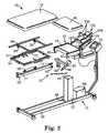
- FIG. 1illustrates a therapeutic apparatus in accordance with the present invention.
- FIG. 2illustrates an exploded view of the therapeutic apparatus of FIG. 1 .
- FIG. 3illustrates a patient being treated with a therapeutic apparatus in accordance with the present invention.
- FIG. 4is a cut-away perspective view of the therapeutic apparatus of FIG. 1 .
- FIG. 5illustrates an alternate cut-away view of the therapeutic traction table of FIG. 1 .
- FIG. 6illustrates another cut-away perspective view of the therapeutic apparatus of FIG. 1 .
- FIG. 7illustrates a cervical assembly for use with a therapeutic apparatus in accordance with the present invention.
- FIG. 8is a schematic view of the therapeutic apparatus where the first supporting portion is rotated down from its neutral position in accordance with the present invention.
- FIG. 9is a schematic view of the therapeutic apparatus where the first supporting portion is rotated up from its neutral position in accordance with the present invention.
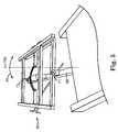
- FIG. 10is a schematic view of the therapeutic apparatus where the head supporting portion is rotated down from its neutral position in accordance with the present invention.
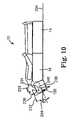
- FIG. 11is a schematic view of the therapeutic apparatus where the head supporting portion is rotated up from its neutral position in accordance with the present invention.
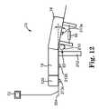
- FIG. 12a schematic view of the therapeutic apparatus with an electrical device adapted to adjust the traction force in accordance with the present invention.
- FIG. 13a schematic view of the therapeutic apparatus with a digital device adapted to adjust the traction force in accordance with the present invention.
- the present inventionprovides a therapeutic apparatus for treating a patient suffering from back pain.
- the apparatusis adapted to exert a therapeutic traction force on a patient's spine to relieve pressures on structures that may be causing pain.
- the apparatusis further capable of producing the forces and positions required to cause decompression of the intervertebral discs, that is, unloading due to distraction and positioning.
- the apparatus provided by the present inventioncan be used to treat many conditions, including, but not limited to back pain, neck pain, herniated disc, protruding disc, degenerative disc disease, posterior facet syndrome and sciatica.
- FIG. 1illustrates a therapeutic apparatus 10 including a support frame 12 having a first body supporting portion 14 and a second body supporting portion 16 .
- First body supporting portion 14is capable of movement relative to second body supporting portion 16 along a longitudinal axis 18 .
- longitudinal axisrefers to the axis along which a body supporting portion can be displaced.
- first body supporting portion 14is adapted to generally support a patient's lower body while second body supporting portion 16 is adapted to support a patient's upper body.
- the present inventionalso contemplates the reverse (i.e. first body supporting portion supporting the patient's upper body and the second body supporting portion supporting the patient's lower body).
- the therapeutic apparatus 10further includes a securing system 20 adapted to secure a patient to the first and second body supporting portions 14 , 16 .
- Linking mechanism 22is adapted to provide movement of the first body supporting portion 14 relative to second body supporting portion 16 along a path comprising at least one rotational degree of freedom.
- rotational degree of freedomrefers to rotational movement of a first body supporting portion relative to a second body supporting portion.
- first body supporting portionis adapted to move along a path comprising up to three degrees of freedom, including, but not limited to yaw movement along path 24 , pitch movement along path 26 , roll movement along path 28 , or a combination thereof.
- Securing system 20is adapted to secure a patient to the first and second body supporting portions 14 , 16 .
- securing system 20includes a first belt 30 attached to the support frame 12 , and extending at least to each side edge of first body supporting portion 14 , and a second belt 32 attached to the support frame 12 and extending at least to each side edge of second body supporting portion 16 in a similar manner.
- first and second belts 30 , 32comprise adjustable and releasable hook and loop fasteners, such as Velcro®.
- the securing system 20can be a Velcro® or other high friction surface on the body supporting surfaces 14 , 16 with or without belts 30 and 32 , pelvic and/or thoracic harnesses, pegs, binders or any combination of these devices.
- FIG. 2illustrates an exploded view of the present therapeutic apparatus 10 .
- Support frame 12includes a base portion 50 , a support member 52 , and a platform portion 53 .
- Base portion 50supports the apparatus and is positioned on a generally horizontal surface.
- Support member 52is secured to base member 50 at a lower portion 59 , and to platform portion 53 at an upper portion 63 .
- Support member 52is thereby positioned in a vertical plane and is adapted to provide support for the first and second body supporting portions.
- Support member 52also includes an actuator (not shown) for increasing or decreasing the height of the first and second body supporting portions relative to the base portion 50 .
- Suitable actuatorsinclude pneumatic or hydraulic cylinders, linear motors, worm gears, rack and pinion systems, and the like.
- support member 52is capable of adjustment between about 25 inches to about 35 inches and is powered by a central source of compressed air 68 .
- linking mechanism 22comprises cantilever arm 58 , yaw mechanism 60 , pitch mechanism 62 and roll mechanism 64 .
- Cantilever arm 58is pivotally attached to pitch mechanism 62 by yaw mechanism 60 at pivot point 61 (See FIG. 6 ).
- Pitch mechanism 62is pivotally attached to platform portion 53 at pivot points 65 and 67 .
- Roll mechanism 64is pivotally attached to cantilever arm 58 at pivot points 71 and 73 .
- An actuator 66can be secured to pitch mechanism 62 at lever 69 , the actuator being adapted to facilitate movement along a path comprising at least one rotational degree of freedom, preferably facilitating at least pitch movement along path 26 (see FIG. 1 ).
- an actuator of the present inventionis preferably powered by a single central source of compressed air 68 .
- Sliding mechanism 54is slidably attached to roll mechanism 64 .
- sliding mechanism 54includes rollers 55 that slide in tracks 57 on roll mechanism 64 , although a variety of structures could be used.
- First body supporting portion 14is secured to sliding mechanism 54 and is thereby capable of movement along longitudinal axis 18 , as shown in FIG. 1 .
- first body supporting portion 14is capable moving up to 6 inches along longitudinal axis 18 .
- Actuator 56can be secured to sliding mechanism 54 to facilitate movement of the first body supporting portion along longitudinal axis 18 .
- Any type of suitable actuatorcan be used, including a pneumatic actuator, hydraulic actuator, rack and pinion structures, linear motors, worm gear, solenoids, and the like.
- actuator 56is a double acting piston powered by a central source of compressed air 68 and is capable of moving first body supporting portion 14 along longitudinal axis 18 with a force of up to about 200 pounds.
- the present therapeutic apparatus 10permits the actuator 56 to apply or remove a traction force to the patient without interfering with the operation of the yaw mechanism 60 , pitch mechanism 62 or roll mechanism 64 .
- any one or all of the yaw mechanism 60 , pitch mechanism 62 and roll mechanism 64can be adjusted before, during or after a traction force is applied to a patient.
- the therapeutic apparatus 10has the added advantage that there are no rope and pulleys to interfere with the operation of the yaw mechanism 60 , pitch mechanism 62 and/or roll mechanism 64 during traction.
- Processor 70receives input data, processes that data and communicates with a central source of compressed air 68 in response.
- the processorhas a digital display, incorporating touch screen capabilities.
- Processor 70is adapted to receive, process and communicate to the traction apparatus almost any relevant treatment data, including the type of force (e.g. static or intermittent), force ramp up and ramp down times, force hold and rest times, magnitude of hold and rest forces, and treatment times.
- the processor 70is adapted to automatically adjusting the table height and/or pitch movement of the apparatus, as well as a patient control switch adapted to terminate treatment.
- “processor”refers to any of a variety of general purpose or special purpose programmable computing devices, such as for example a PC or a programmable logic controller.
- the processor 70is a separate stand-alone computer, such as a PC.
- the processor 70can also store and retrieve pre-programmed traction protocols.
- the therapistmay develop a protocol for a particular patient that can be applied multiple time over the course of treatment. This protocol can be stored in the processor 70 for future use.
- a protocolcan include any of the treatment variable available in the processor 70 , including without limitation the type of force (e.g. static or intermittent), force ramp up and ramp down times, force hold and rest times, magnitude of hold and rest forces, and treatment times.
- the processor 70also preferably assigns an index number or title to each protocol so that they can be easily retrieved.
- the therapistgenerates a treatment protocol off-line on a separate computer system, such as a PC.
- the protocolis then uploaded to the processor 70 using conventional computer communication protocols and techniques, such as an RS-232 connection.
- This embodimentpermits the treatment protocol to be sent electronically to other clinics at which the patient can receive treatment.
- One method of electronically transmitting a treatment protocolis using electronic mail over the Internet.
- FIGS. 4 , 5 and 6show views of a portion of the present invention and illustrate examples of different rotational degrees of freedom of which first body supporting portion 14 is adapted to move relative to second body supporting portion 16 .
- roll mechanism 64is pivotally secured to cantilever arm 58 at pivot points 71 and 73 to provide roll movement along path 28 about axis 90 . It is preferable that roll mechanism 64 be capable of providing first body supporting portion 14 with up to about 15 degrees of rotation from the neutral position in either a clockwise or counterclockwise direction.
- yaw mechanism 60(see FIG. 6 ) is pivotally attached to pitch mechanism 62 at pivot point 61 (see FIG. 6 ) and is adapted to rotate cantilever arm 58 about axis 100 to provide yaw movement of the first body supporting portion 14 (see FIG. 1 ) along path 24 .
- yaw mechanism 60is capable of providing the first body supporting portion 14 up to about 15 degrees of rotation in either direction from the neutral position.
- pitch mechanism 62is secured to platform portion 53 at pivot points 65 and 67 and is adapted to rotate cantilever arm 58 about axis 110 to provide pitch movement along path 26 , as shown in FIG. 1 .
- FIG. 6illustrates rotation flexed above the neutral position
- embodiments of the present inventioncan also extend below neutral.
- Preferred embodiments of the present inventionare capable of flexing up to about 25 degrees and extending down to about 20 degrees from the neutral position.
- FIGS. 4 , 5 and 6each illustrate movement along a path defined by one rotational degree of freedom (e.g., pitch, roll or yaw)
- the present therapeutic apparatus 10is capable of movement along paths that comprise two or more rotational degrees of freedom. That is, each of the rotational degrees of freedom are preferably independently and simultaneously adjustable.
- the first body supporting structureis capable of simultaneous movement along a path having three rotational degrees of freedom, comprising roll, yaw and pitch movement.
- the longitudinal axis 18comprises the axis of movement of the sliding mechanism 54 relative to the cantilever arm 58 .
- This movement along the longitudinal axis 18is independent of the three degrees of freedom.
- the path upon which first body supporting portion 14 is positionedaffects the direction and angle of its movement relative to second body supporting portion 16 along longitudinal axis 18 . For example, if first body supporting portion 14 is positioned along path 26 , 10 degrees above the neutral position, then longitudinal axis 18 will be located 10 degrees above the location of longitudinal axis 18 in FIG. 1 .
- the present inventionprovides at least one locking mechanism for releasably retaining first body supporting portion 14 along the path comprising at least one rotational degree of freedom.
- the apparatusmay further provide a locking mechanism for releasably retaining the first body supporting portion 14 from movement along longitudinal axis 18 .
- FIG. 4illustrates a first locking mechanism 94 adapted to releasably retain first body supporting portion 14 from longitudinal movement.
- Second locking mechanism 96is adapted to releasably retain first body supporting portion 14 from yaw movement along path 24 and third locking member 98 is adapted to releasably retain first body supporting portion 14 from roll movement along path 28 .
- at least one locking mechanismis provided for each rotational degree of freedom.
- the locking mechanisms 94 , 96 , 98are an infinitely positionable mechanical lock, such as disclosed in U.S. Pat. No. 4,577,730 (Porter), or the linear positioning devices sold under the trade name Mecklok® from P. L. Porter Company of Woodland Hills, Calif.
- the locking mechanisms 94 , 96 , 98are preferably biased to a locked position.
- the locked positionis released using the handles indicated by the reference numerals.
- the operatormanually releases one or more of the locking mechanisms 94 , 96 , 98 and positions the first body supporting portion 14 in the desired configuration. Releasing the handle re-engages the locking mechanism 94 , 96 , 98 .
- Positioning the first body supporting portion 14 along any combination of the three rotational degrees of freedomdoes not interfere with the movement of the sliding mechanism 54 along the longitudinal axis 18 .
- an apparatus of the present inventionmay also provide a head supporting portion 120 for generally supporting the head of the patient.
- Head supporting portion 120is slidingly attached to frame 134 .
- the frame 134is pivotally attached to platform portion 53 at pivot points 124 , 126 (See FIG. 2 ), and is adapted to move along path 122 .
- the frame 134is adapted to rotate at pivot points 124 , 126 up to about 30 degrees from a horizontal plane.
- Locking mechanism 130is provided for releasably retaining the frame 134 and head supporting portion 120 at various locations along path 122 .
- the head supporting portion 120is adapted to move relative to frame 134 along an axis 132 under the power of actuator 128 .
- Actuator 128is preferably powered by the central source of compressed air 68 (see FIG. 2 ) to generate the cervical traction force.
- the single power source 68operates all of the actuators 56 , 66 , 128 .
- Neck wedges 136are preferably used to retain the patient's head to the head supporting portion 120 (see FIG. 2 ). The location of the neck wedges 136 is preferably adjusted to accommodate patients of different sizes.
- Head strap 121can optionally be used to retain the patient's head to the head supporting portion 120 .
- a cervical traction assembly with adjustable neck wedges suitable for use in the present inventionis disclosed in U.S. patent application Ser. No. 08/817,444, entitled Portable Traction Device and U.S. Pat. No. 6,171,273.
- the processor 70preferably retains cervical traction protocols as well.
- FIG. 3illustrates a patient being treated on an apparatus of the present invention.
- Support member 52is adjusted to a height that easily facilitates a patient mounting the apparatus.
- First body supporting portion 14is then moved along a path comprising at least one rotational degree of freedom to accommodate for any postural deformities of the patient.
- the patientis then placed and supported on the first and second body supporting portions 14 , 16 in either a prone or supine position, and is secured to first body and second body supporting portions 14 , 16 by securing system 20 .
- FIG. 3illustrates a patient being treated on an apparatus of the present invention.
- Support member 52is adjusted to a height that easily facilitates a patient mounting the apparatus.
- First body supporting portion 14is then moved along a path comprising at least one rotational degree of freedom to accommodate for any postural deformities of the patient.
- the patientis then placed and supported on the first and second body supporting portions 14 , 16 in either a prone or supine position, and is secured to first body and
- first body supporting portion 14is moved relative to second body supporting portion 16 along longitudinal axis 18 (see FIG. 1 ). As the distance between the first and second body supporting portion is increased, a traction force is applied to the patient's lumbar region by the first and second belts. Further, because the first body supporting portion 14 has been moved along a path comprising at least one rotational degree of freedom, the traction force is applied at an angle that compensates for a patient's postural deformities. As the distance between the first and second body supporting portions is decreased, the traction force applied to the patient's lumbar region is decreases.
- first body supporting portion 14can be moved along a path comprising at least one rotational degree of freedom after the patient is secured to the table and even during the application of traction force to the patient.
- the tablecan be releasably retained anywhere along the path during treatment to accommodate the patient's condition. It may even be desirable to retain first body supporting portion 14 at multiple locations along a path during a treatment cycle.
- the traction force created by first body supporting portion 14 moving away from second body supporting portion 16 along longitudinal axis 18can be static (i.e.
- the patientcan be treated in either the supine or prone position and/or both, without adjusting the apparatus.
- a treatment protocolcan be entered into processor 70 to facilitate some or all of the therapeutic steps.
- processor 70provides a touch control screen to assist a health care professional in entering the treatment protocol.
- Data inputsuch as the mode of lumbar treatment (e.g. static or intermittent), force ramp up time, force ramp down time, hold time, rest time, rest force, maximum force, and treatment time can all be entered to create a desired treatment protocol.
- the processor 70communicates with the power source (in the illustrated embodiment the source of compressed air 68 ) to power the actuators 56 , 66 , 128 and to provide the designated movement between the first body supporting portion, second body supporting portions, and/or the head supporting portion 14 , 16 , 120 .
- Performance characteristics of the present inventioninclude improved ability to treat patients with postural deformities, greater ease in the treatment of patients, and reduced set-up time.
- an apparatus of the present inventioncan treat patients with postural deformities who could not be adequately treated with conventional traction devices.
- the securing system 20provides a more efficient and less cumbersome mechanism of applying traction force to a patient.
- a single or series of patientscan be treated in either the prone or supine position or both, without adjusting or altering an apparatus of the present invention.
- the inventionhas improved performance characteristics, while also being easier and faster to use.
- FIG. 8is a schematic view of the therapeutic apparatus 10 generally as illustrated in FIG. 1 with the first body supporting portion 14 rotated down from a neutral (horizontal) position relative to the horizontal plane 204 .
- the downward slope of the first body supporting portion 14can cause the traction force to be greater than intended due to the influence of gravity. That is, gravity acting on the first body supporting portion 14 and the portion of the patients body supported thereon adds the forces 224 and 226 to the desired traction force 230 .
- the present inventionuses the force vectors for the weight 222 of the tilted first body supporting portion 14 and the weight 220 of the applicable portion of the patient's body 202 supported by the body supporting portion 14 to calculate a compensating force along the longitudinal axis 18 of the tilted first body supporting portion 14 .
- the phrase “compensating forces”refers to force vectors along a longitudinal axis of a tilted body supporting portion of a therapeutic apparatus, which accommodate for the weight of the tilted body supporting portion and the weight of the applicable portion of the patient's body supported by the body supporting portion during traction.
- the compensating forces 224 and 226are either added to or subtracted from a delivered traction force 230 depending upon whether the first body supporting portion 14 is rotated up or rotated down from its neutral position on the horizontal plane 204 . As shown in FIG. 8 , when the first body supporting portion 14 is rotated down from its neutral position, the compensating forces 224 and 226 will be subtracted from the delivered traction force 230 .
- FIG. 9is a schematic view of the therapeutic apparatus 10 generally as illustrated in FIG. 1 with the first body supporting portion 14 rotated up from its neutral (horizontal) position relative to the horizontal plane 204 . Again, due to the influence of gravity the upward slope of the first body supporting portion 14 may cause the traction force to be less than intended. When the first body supporting portion 14 is rotated up from its neutral position, the compensating forces 224 and 226 is typically added to the delivered traction force.
- An estimate of the applicable portion of the patient supported by the body supporting portioncan be calculated according to the following body mass distribution table.
- the total body weight of a male patient on the therapeutic apparatus 10is about 200 pounds in FIG. 8 .
- His tilted lower body 202 on the tilted first supporting portion 14includes his hip, thighs, lower legs, and feet.
- an ordinary human being's lower body weightis equal to approximately 44% of his or her total body weight.
- the patient's lower body weight 220is about 88 pounds (200 pounds*44%).
- the weight 222 of the tilted first body supporting portion 14 of the therapeutic apparatus 10is fixed at about 22 pounds.
- the first supporting portion 14is rotated down about 10 degrees from the horizontal plane 204 .
- the same male patientis treated in this example.
- the head supporting portion 120is rotated down about 10 degrees from the horizontal plane 204 .
- an ordinary human being's head and neck weightis equal to approximately 8% of his or her total body weight.
- the weight 234 of patient's head and neck 203is about 16 pounds (200 pounds* 8%).
- the weight 236 of the tilted head supporting portion 120 of the therapeutic apparatus 10is fixed at about 4 pounds.
- the same male patientis treated in this example.
- the head supporting portion 120is rotated up about 5 degrees from the horizontal plane 204 .
- FIG. 12is a schematic view of the therapeutic apparatus generally as illustrated in FIG. 1 capable of automatically implementing the theory of the traction force adjustment discussed above.
- the therapeutic apparatus 10includes an electrical angle measuring device 210 , such as a potentiometer, attached to the pitch mechanism 62 .
- the angle measuring device 210provides a signal corresponding to the angle a of first supporting portion 14 relative to the horizontal plane 204 .
- the angle measuring device 210can also measure the angle of the second supporting portion 16 and/or the head support portion 120 relative to the horizontal plane 204 . Any device that generates a signal that is proportional to the angle a can be substituted for the angle measuring device 210 , such as for example an absolute or incremental optical encoder.
- the second body supporting portion 16remains horizontal, while the first body supporting portion 14 and/or the head supporting portion 120 can move relative to horizontal. It is also possible for the second body supporting portion 16 to move relative to horizontal.
- the angle measuring device 210is three discrete devices that generate angle signals for each of the first body supporting portion 14 , the second body supporting portion 16 and the head support portion 120 .
- a weight measuring device 212is optionally attached to the therapeutic apparatus 10 to measure the total body weight of a patient.
- a signal from the weight measuring device 212is transmitted to the process 70 and is used to calculate the adjusted traction force.
- an operatoridentifies the portion of the patient supported by one of the supporting portions 14 , 16 , 120 .
- the weight of the apparatus 10is preferably stored in the processor 70 .
- the processor 70uses the weight measuring device 212 to calculate the total weight of the patient.
- the body mass distribution data in Table 1, stored as a look-up table available to the processor 70is used to calculate the weight of the patient supported by the relevant body supporting portion 14 , 16 , 120 .
- a weight measuring device 213 a , 213 b , 213 ccan optionally be provided on one or more of the first body supporting portion 14 , the second body supporting portion 16 and/or the head support portion 120 , respectively. Signals from the weight measuring devices 213 are preferably transmitted directly to the processor 70 for use in calculating the adjusted traction force. Providing multiple weight measuring devices 213 obviates the need to estimate the portion of the patient's body supported by a particular support portion 14 , 16 , 120 , such as discussed above.
- the weight measuring device 212provides a voltage signal representing the total weight of the patient.
- a percentage of the voltage from a voltage divider of the device 212can be used to represent the weight of the tilted human body on the first body supporting portion 14 .
- the weights of the tilted first and second body supporting portions 14 , 16are fixed and known at the time of manufacture. Accordingly, a constant voltage signal can be used to represent the weight of the tilted first body supporting portion 14 .
- These voltage signalscan be combined using electrical summing and multiplier circuits to provide a signal that represents the compensating forces.
- the signal that represents the compensating forcescan be electrically summed with another signal that controls the actuator 56 , so as to control the adjusted traction force that takes both the weight of the tilted first body supporting portion 14 and the weight of the applicable portion of the patient's body into account.
- the weight measuring device 212can also be used to control the adjusted traction force that takes both the weight of the head support portion 120 and the weight of the head and neck of the patient into account.
- the electronic signals from the angle measuring device 210 and weight measuring devices 212 and/or 213can be directed to an electronic display indicating. The operator then uses this angle and weight information to calculate the adjusted traction force.
- the signals from the angle measuring device 210 and the weight measuring devices 212 and/or 213can be directed to the processor 70 .
- the processor 70preferably measures the weight supported by the supporting portions 14 , 16 , 120 directly. Alternatively, the operator inputs the portions of the patient's body supported by the body supporting portion 14 , 16 , 120 that is tilted relative to horizontal.
- the processor 70optionally includes a data entry device, such as a keypad.
- the processor 70calculates the adjusted traction force.
- the adjusted traction forcecan be entered into the processor 70 by the operator or the processor 70 can control the operation of one or more of the actuators 56 , 66 (see FIG. 2 ) to apply the adjusted traction force.
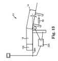
- FIG. 13is a schematic view of the therapeutic apparatus in accordance with the present invention.
- the therapeutic apparatus 10includes a digital control system 220 capable of determining the angle a that the supporting portions 14 , 16 , 120 are moved relative to horizontal.
- the first body supporting portion 14is tilted relative to the horizontal plane 204 .
- the digital control system 220is also capable of measuring the total and partial body weight of a patient (see FIG. 12 ).
- the body weight percentage distribution informationcan be stored in the system 220 , so that the weight of the applicable portion of the patient's body on the first body supporting portion 14 can be digitally computed.
- the weight supported by each support portion 14 , 16 , 120can be measured directly and communicated to the digital control system 220 .
- the weight of the tilted first body supporting portion 14is fixed and known at the time of manufacture. This weight is preferably stored in the digital control system 220 . Once the adjusted traction force is calculated, the digital control system 220 controls the actuator 56 to apply the traction force.
Landscapes
- Health & Medical Sciences (AREA)
- Life Sciences & Earth Sciences (AREA)
- Animal Behavior & Ethology (AREA)
- Veterinary Medicine (AREA)
- Public Health (AREA)
- General Health & Medical Sciences (AREA)
- Rehabilitation Therapy (AREA)
- Physical Education & Sports Medicine (AREA)
- Pain & Pain Management (AREA)
- Epidemiology (AREA)
- Orthopedic Medicine & Surgery (AREA)
- Engineering & Computer Science (AREA)
- Biomedical Technology (AREA)
- Nursing (AREA)
- Heart & Thoracic Surgery (AREA)
- Vascular Medicine (AREA)
- Neurology (AREA)
- Biophysics (AREA)
- Orthopedics, Nursing, And Contraception (AREA)
Abstract
Description
| TABLE 1 | |||
| Body Portion | Percentage of Total Body Mass | ||
| Head/Neck | about 8% | ||
| Hips | about 12% | ||
| Thighs | about 20% | ||
| Lower Legs | about 9.2% | ||
| Feet | about 3% | ||
The mathematical formula for calculating the compensating forces is determined according to the equation below:
Compensating forces=Sin (Acute Angle Between Tilted Body Supporting Portion of Therapeutic Apparatus and Horizontal Plane)*(Weight of Tilted Body Supporting Portion+Weight of Applicable Portion of Patient)
Adjusting the delivered traction force by the compensating forces will yield an adjusted traction force. As used herein, the phrase “adjusted traction force” represents a traction force that is modified to take the compensating forces into account. The mathematical formula for calculating the adjusted force is determined according to whether the force of gravity increases or decreases the delivered traction force. If the body supporting portion is rotated down from its neutral position, then Adjusted Traction Force=Delivered Traction Force−Compensating Forces. If the body supporting portion is rotated up from its neutral position, then Adjusted Traction Force=Delivered Traction Force+Compensating Forces.
Sin(10°)*(22 pounds+88 pounds)=17.4 pounds
Therefore, when delivering a
Sin(15′)*(22 pounds+88 pounds)=28.5 pounds
Therefore, when delivering a
Sin(10°)*(4 pounds+16 pounds)=3.5 pounds
Therefore, when delivering a
Sin(5°)*(4 pounds+16 pounds)=1.7 pounds
Therefore, when delivering a
Claims (24)
Priority Applications (2)
| Application Number | Priority Date | Filing Date | Title |
|---|---|---|---|
| US10/715,008US6971997B1 (en) | 2002-01-22 | 2003-11-17 | Multi-axis cervical and lumber traction table |
| US11/284,196US20060074366A1 (en) | 2002-01-22 | 2005-11-21 | Multi-axis cervical and lumbar traction table |
Applications Claiming Priority (2)
| Application Number | Priority Date | Filing Date | Title |
|---|---|---|---|
| US10/054,631US7189214B1 (en) | 2002-01-22 | 2002-01-22 | Multi-axis cervical and lumbar traction table |
| US10/715,008US6971997B1 (en) | 2002-01-22 | 2003-11-17 | Multi-axis cervical and lumber traction table |
Related Parent Applications (1)
| Application Number | Title | Priority Date | Filing Date |
|---|---|---|---|
| US10/054,631Continuation-In-PartUS7189214B1 (en) | 2002-01-22 | 2002-01-22 | Multi-axis cervical and lumbar traction table |
Related Child Applications (1)
| Application Number | Title | Priority Date | Filing Date |
|---|---|---|---|
| US11/284,196ContinuationUS20060074366A1 (en) | 2002-01-22 | 2005-11-21 | Multi-axis cervical and lumbar traction table |
Publications (1)
| Publication Number | Publication Date |
|---|---|
| US6971997B1true US6971997B1 (en) | 2005-12-06 |
Family
ID=35430371
Family Applications (3)
| Application Number | Title | Priority Date | Filing Date |
|---|---|---|---|
| US10/054,631Expired - LifetimeUS7189214B1 (en) | 2002-01-22 | 2002-01-22 | Multi-axis cervical and lumbar traction table |
| US10/715,008Expired - LifetimeUS6971997B1 (en) | 2002-01-22 | 2003-11-17 | Multi-axis cervical and lumber traction table |
| US11/284,196AbandonedUS20060074366A1 (en) | 2002-01-22 | 2005-11-21 | Multi-axis cervical and lumbar traction table |
Family Applications Before (1)
| Application Number | Title | Priority Date | Filing Date |
|---|---|---|---|
| US10/054,631Expired - LifetimeUS7189214B1 (en) | 2002-01-22 | 2002-01-22 | Multi-axis cervical and lumbar traction table |
Family Applications After (1)
| Application Number | Title | Priority Date | Filing Date |
|---|---|---|---|
| US11/284,196AbandonedUS20060074366A1 (en) | 2002-01-22 | 2005-11-21 | Multi-axis cervical and lumbar traction table |
Country Status (1)
| Country | Link |
|---|---|
| US (3) | US7189214B1 (en) |
Cited By (78)
| Publication number | Priority date | Publication date | Assignee | Title |
|---|---|---|---|---|
| US20040092854A1 (en)* | 2002-09-10 | 2004-05-13 | D'amico Anthony T. | Traction device for physical therapy |
| US20060149178A1 (en)* | 2004-12-30 | 2006-07-06 | Dunfee Matthew J | Ambulatory spinal unloading method and apparatus |
| US7321811B1 (en) | 2006-09-14 | 2008-01-22 | Rawls-Meehan Martin B | Methods and systems of adjustable bed position control |
| EP1985277A1 (en)* | 2007-04-25 | 2008-10-29 | BackProject Corporation | Restraint, Reposition, Traction and Exercise Device |
| EP1991192A2 (en)* | 2006-02-17 | 2008-11-19 | O'Malley, Jeanne | Physiotherapeutic and physical training devices |
| WO2008059497A3 (en)* | 2006-11-15 | 2009-04-16 | Headway Ltd | Dynamic cradle, especially for treating head and neck pain |
| US20090100599A1 (en)* | 2006-09-14 | 2009-04-23 | Rawls-Meehan Martin B | Adjustable bed position control |
| US20090247917A1 (en)* | 2008-03-25 | 2009-10-01 | Dong Rae Park | Massaging device |
| US20090281570A1 (en)* | 2008-05-06 | 2009-11-12 | Dicerbo Mary T M | System and Method for Treating Cervical Vertebrae |
| WO2009143673A1 (en)* | 2008-05-29 | 2009-12-03 | 北京三维正基科技有限公司 | Spinal three-dimensional orthopaedic equipment |
| US7648473B1 (en)* | 2006-09-18 | 2010-01-19 | Jedheesh Peruvingal | Traction extension table |
| RU2394529C1 (en)* | 2009-03-19 | 2010-07-20 | Михаил Леонидович Грязнов | Device for traction and correction of spine |
| US20100280548A1 (en)* | 2009-01-06 | 2010-11-04 | Yen Sunto | Vertical rehabilitation appliance |
| US20110099716A1 (en)* | 2005-02-22 | 2011-05-05 | Jackson Roger P | Patient positioning support structure |
| US20110107516A1 (en)* | 2005-02-22 | 2011-05-12 | Jackson Roger P | Patient positioning support structure with trunk translator |
| US20110137343A1 (en)* | 2009-12-08 | 2011-06-09 | Spinal Innovations, Llc | Portable spinal disc decompression device |
| US8069512B2 (en) | 2006-09-14 | 2011-12-06 | Martin B Rawls-Meehan | Adjustable bed frame |
| US8100846B1 (en) | 2007-10-15 | 2012-01-24 | Lamonica John J | Spinal traction and restoration using pointable constrained inflator |
| CN101947175B (en)* | 2009-07-10 | 2012-07-04 | 高福懋 | multifunctional back exercise device |
| CN102551943A (en)* | 2012-01-15 | 2012-07-11 | 宋传彬 | Three-dimensional space cervical vertebrae rehabilitation instrument |
| ITBG20120037A1 (en)* | 2012-07-18 | 2014-01-19 | Tecnobody S R L | POSTURAL TABLE FOR SENSORIZED PHYSICAL THERAPY |
| US8719979B2 (en) | 2005-02-22 | 2014-05-13 | Roger P. Jackson | Patient positioning support structure |
| ITRM20120585A1 (en)* | 2012-11-21 | 2014-05-22 | Chama Abdulkarim | "SYSTEM FOR THE TREATMENT OF OSTEOPATHIC INJURIES OF THE BASIN" |
| ITRM20120596A1 (en)* | 2012-11-27 | 2014-05-28 | Bios Project Srl | MASSAGE MACHINE WITH TILTING BED PROVIDED FOR SITTING |
| EP2180855A4 (en)* | 2007-08-08 | 2014-09-03 | Ajoo Medics Co Ltd | Spinal correction apparatus |
| WO2014152651A1 (en)* | 2013-03-14 | 2014-09-25 | Milly Products, Llc | Spinal and neck decompression apparatus and method |
| US8844077B2 (en) | 2005-02-22 | 2014-09-30 | Roger P. Jackson | Syncronized patient elevation and positioning apparatus positioning support systems |
| US8909357B2 (en) | 2007-09-14 | 2014-12-09 | Martin B Rawls-Meehan | System for tandem bed communication |
| US8926535B2 (en) | 2006-09-14 | 2015-01-06 | Martin B. Rawls-Meehan | Adjustable bed position control |
| CN104644376A (en)* | 2013-11-22 | 2015-05-27 | 保罗·塞尔吉奥·贝尔维安 | passive exercise machine |
| US9044366B2 (en) | 2006-09-14 | 2015-06-02 | Ascion, Llc | Adjustable mattress support facility |
| USD733452S1 (en) | 2010-02-09 | 2015-07-07 | Ascion, Llc | Adjustable bed |
| USD736023S1 (en) | 2013-01-25 | 2015-08-11 | Ascion, Llc | Adjustable bed |
| US9173793B2 (en) | 2006-09-14 | 2015-11-03 | Ascion, Llc | Adjustable bed frame with mattress retaining brackets |
| ES2551056A1 (en)* | 2015-09-21 | 2015-11-13 | Carlos Fradera Pellicer | Therapeutic device (Machine-translation by Google Translate, not legally binding) |
| US9265679B2 (en) | 2005-02-22 | 2016-02-23 | Roger P Jackson | Cantilevered patient positioning support structure |
| US9301897B2 (en) | 2005-02-22 | 2016-04-05 | Roger P. Jackson | Patient positioning support structure |
| US9339430B2 (en) | 2006-05-05 | 2016-05-17 | Roger P. Jackson | Patient positioning support apparatus with virtual pivot-shift pelvic pads, upper body stabilization and fail-safe table attachment mechanism |
| US9345611B2 (en) | 2011-05-11 | 2016-05-24 | Backproject Corporation | Cervical repositioning, restraint, traction and exercise device and method |
| US9358170B2 (en) | 2007-10-22 | 2016-06-07 | Roger P Jackson | Surgery table apparatus |
| US9402775B2 (en) | 2014-07-07 | 2016-08-02 | Roger P. Jackson | Single and dual column patient positioning and support structure |
| US9402759B2 (en) | 2013-02-05 | 2016-08-02 | Bonutti Research, Inc. | Cervical traction systems and method |
| US9433546B2 (en) | 2006-09-14 | 2016-09-06 | Ascion, Llc | Dual motion deck-on-deck bed frame |
| US9468576B2 (en) | 2005-02-22 | 2016-10-18 | Roger P. Jackson | Patient support apparatus with body slide position digitally coordinated with hinge angle |
| US9549863B2 (en) | 2014-07-07 | 2017-01-24 | Roger P. Jackson | Surgical table with pivoting and translating hinge |
| US9561145B2 (en) | 2012-02-07 | 2017-02-07 | Roger P. Jackson | Fail-safe release mechanism for use with patient positioning support apparati |
| US9629473B2 (en) | 2009-02-09 | 2017-04-25 | Ascion, Llc | Leg assembly |
| US9636266B2 (en) | 2005-02-22 | 2017-05-02 | Roger P. Jackson | Synchronized patient elevation and positioning apparatus for use with patient positioning support systems |
| US9642760B2 (en) | 2006-05-05 | 2017-05-09 | Roger P. Jackson | Patient positioning support apparatus with virtual pivot-shift pelvic pads, upper body stabilization and fail-safe table attachment mechanism |
| US20170143564A1 (en)* | 2015-11-23 | 2017-05-25 | Cardon Rehabilitation & Medical Equipment Ltd. | Multi-positional section for a treatment table |
| CN106726065A (en)* | 2016-12-27 | 2017-05-31 | 安徽瑞德医疗设备制造有限公司 | A kind of No operation Cervical vertebrae pressure-reducing treatment headrest and its pulling control |
| WO2017098463A1 (en)* | 2015-12-09 | 2017-06-15 | Stellenbosch University | Cervical spine traction apparatus |
| US9681977B2 (en) | 2000-12-01 | 2017-06-20 | Bonutti Research, Inc. | Apparatus and method for spinal distraction |
| US9707147B2 (en) | 2009-12-17 | 2017-07-18 | Headway Ltd. | “Teach and repeat” method and apparatus for physiotherapeutic applications |
| US20170239127A1 (en)* | 2016-02-19 | 2017-08-24 | Jin Han Park | Backbone retraction apparatus |
| US9744087B2 (en) | 2005-02-22 | 2017-08-29 | Roger P. Jackson | Patient support apparatus with body slide position digitally coordinated with hinge angle |
| US9849054B2 (en) | 2005-02-22 | 2017-12-26 | Roger P. Jackson | Patient positioning support structure |
| US9968503B2 (en) | 2012-04-16 | 2018-05-15 | Allen Medical Systems, Inc. | Dual column surgical table having a single-handle unlock for table rotation |
| US10064784B2 (en) | 2006-09-14 | 2018-09-04 | Martin B. Rawls-Meehan | System and method of an adjustable bed with a vibration motor |
| US10080543B2 (en)* | 2014-12-01 | 2018-09-25 | General Electric Company | Integrated modular system for managing plurality of medical devices |
| AT520259A1 (en)* | 2017-07-19 | 2019-02-15 | Alexander Gotthardt Mag | therapy couch |
| CN109350332A (en)* | 2018-09-14 | 2019-02-19 | 张禧梅 | A kind of cervical traction bed for medical orthopaedics patient |
| CN109394404A (en)* | 2017-08-16 | 2019-03-01 | (株)神话医疗器 | Spinal treatment instrument |
| US10363189B2 (en) | 2015-10-23 | 2019-07-30 | Allen Medical Systems, Inc. | Surgical patient support for accommodating lateral-to-prone patient positioning |
| US10369069B2 (en) | 2014-10-07 | 2019-08-06 | Allen Medical Systems, Inc. | Surgical arm positioning systems and methods |
| US10492973B2 (en) | 2015-01-05 | 2019-12-03 | Allen Medical Systems, Inc. | Dual modality prone spine patient support apparatuses |
| US10548793B2 (en) | 2016-06-14 | 2020-02-04 | Allen Medical Systems, Inc. | Pinless loading for spine table |
| US10561559B2 (en) | 2015-10-23 | 2020-02-18 | Allen Medical Systems, Inc. | Surgical patient support system and method for lateral-to-prone support of a patient during spine surgery |
| CN111067758A (en)* | 2019-12-30 | 2020-04-28 | 东莞市护康健康管理有限公司 | Lumbar vertebra traction bed with pedal limiting function |
| US10864137B2 (en) | 2006-09-14 | 2020-12-15 | Ascion, Llc | System and method of an adjustable bed with a vibration motor |
| US10869798B2 (en) | 2006-05-05 | 2020-12-22 | Warsaw Orthopedic, Inc. | Patient positioning support apparatus with virtual pivot-shift pelvic pads, upper body stabilization and fail-safe table attachment mechanism |
| US11051770B2 (en) | 2005-02-22 | 2021-07-06 | Warsaw Orthopedic, Inc. | Patient positioning support structure |
| US11202731B2 (en) | 2018-02-28 | 2021-12-21 | Allen Medical Systems, Inc. | Surgical patient support and methods thereof |
| US11213448B2 (en) | 2017-07-31 | 2022-01-04 | Allen Medical Systems, Inc. | Rotation lockout for surgical support |
| US11432980B2 (en)* | 2020-03-13 | 2022-09-06 | Stephen Barr | Scoliosis correction table |
| US11471354B2 (en) | 2018-08-30 | 2022-10-18 | Allen Medical Systems, Inc. | Patient support with selectable pivot |
| US11484458B2 (en)* | 2019-10-04 | 2022-11-01 | Akademia Gorniczo-Hutnicza Im. Stanislawa Staszica W Krakowie | Device for spine rehabilitation and method of spine rehabilitation using said device for spine rehabilitation |
| US12011399B2 (en) | 2013-08-28 | 2024-06-18 | Warsaw Orthopedic, Inc. | Patient positioning support apparatus with fail-safe connector attachment mechanism |
Families Citing this family (81)
| Publication number | Priority date | Publication date | Assignee | Title |
|---|---|---|---|---|
| AU2003297954A1 (en)* | 2002-12-16 | 2004-07-22 | Cert Health Sciences, Llc | Method and apparatus for therapeutic treatment of back pain |
| US20080167684A1 (en)* | 2003-04-15 | 2008-07-10 | Cuccia David F | Treatment table with calf/foot assembly and method of use |
| US7717870B2 (en)* | 2003-12-30 | 2010-05-18 | North American Medical Corporation | System and method for providing decompression modalities using oscillatory signaling at high tension levels and smooth transition signaling for spinal treatment |
| US20060287619A1 (en)* | 2003-12-30 | 2006-12-21 | North American Medical Corporation | System and method for providing decompression modalities using smooth transition signaling and oscillatory signaling at high tension levels for spinal treatment |
| US20060142683A1 (en)* | 2004-12-28 | 2006-06-29 | Axiom Worldwide, Inc. | Spinal decompression therapy system and method |
| US9308145B2 (en) | 2005-02-22 | 2016-04-12 | Roger P. Jackson | Patient positioning support structure |
| US7654974B2 (en)* | 2005-04-01 | 2010-02-02 | David B. Bass | Recliner spinal traction device |
| US20070106192A1 (en)* | 2005-09-23 | 2007-05-10 | Axiom Worldwide, Inc. | System and method for treating the spine with light therapy |
| WO2007075005A1 (en)* | 2005-12-26 | 2007-07-05 | Hag Chung Kim | Exercise apparatus for backbone remedy |
| US20070208289A1 (en)* | 2006-03-03 | 2007-09-06 | Jay Walther | Systems and methods for providing light therapy traction |
| US20070208396A1 (en)* | 2006-03-03 | 2007-09-06 | Gary Whatcott | Systems and methods for providing a dynamic light pad |
| FR2905851B1 (en)* | 2006-09-15 | 2009-04-10 | Denis Berthet | AUTOMATED MECHANICAL DEVICE FOR PROLONGED MULTI - DIMENSIONAL PASSIVE SPEED MOBILIZATION. |
| US7846080B2 (en)* | 2007-01-12 | 2010-12-07 | Boren John P | Machine and method for head, neck and, shoulder stretching |
| US20080176716A1 (en)* | 2007-01-12 | 2008-07-24 | Boren John P | Vertical Lumbar Stretching Machine and Method |
| US20080188780A1 (en)* | 2007-02-02 | 2008-08-07 | North American Medical Corporation | Spinal distraction device with three dimensionally vibrating matrix head |
| USD633829S1 (en)* | 2007-11-26 | 2011-03-08 | Mao-Kuan Chang | Medical steady structure |
| US8146189B2 (en)* | 2007-11-30 | 2012-04-03 | Jun Yang | Patient alignment device |
| RU2368368C1 (en)* | 2008-06-26 | 2009-09-27 | Алексей Георгиевич Глазун | Rehabilitation spinal stand |
| WO2010039105A1 (en)* | 2008-09-30 | 2010-04-08 | Dyer Allen E | Dynamic logarithmic spinal decompression table and method |
| WO2010120165A1 (en)* | 2009-04-16 | 2010-10-21 | Yama Zafer | Apparatus and method for treatment of back and neck ailments |
| CN101690690B (en)* | 2009-09-25 | 2013-12-04 | 明斌 | Portable prostrate massage bed for spinal column correction |
| US8235877B2 (en)* | 2010-03-05 | 2012-08-07 | Boren John P | Apparatus and method of gravity-assisted spinal stretching |
| US8133260B1 (en)* | 2011-01-06 | 2012-03-13 | Bernwart Kellner | Chiropractic table apparatus and method of use |
| US9446260B2 (en) | 2011-03-15 | 2016-09-20 | Mark Jagger | Computer controlled laser therapy treatment table |
| US10786412B2 (en) | 2011-03-15 | 2020-09-29 | Mark Jagger | Computer controlled laser therapy treatment table |
| US20130008452A1 (en)* | 2011-06-30 | 2013-01-10 | Steven Evangelos | Training and Rehabilitation Device |
| US8464720B1 (en) | 2012-01-10 | 2013-06-18 | Alessio Pigazzi | Method of securing a patient onto an operating table when the patient is in the trendelenburg position and apparatus therefor including a kit |
| US10322050B1 (en) | 2012-01-10 | 2019-06-18 | Alessio Pigazzi | Method of securing a patient onto an operating table when the patient is in a position such as the Trendelenburg position and apparatus therefor including a kit |
| US10912699B2 (en) | 2012-01-10 | 2021-02-09 | Alessio Pigazzi | Method of securing a patient onto an operating table when the patient is in a position such as the trendelenburg position and apparatus therefor including a kit |
| US20130261510A1 (en)* | 2012-04-03 | 2013-10-03 | Ergo-Flex Technologies, LLC | Reclinable therapeutic massage chair |
| USD726077S1 (en)* | 2012-10-10 | 2015-04-07 | Arjo Hospital Equipment Ab | Shower stretcher |
| US10004626B1 (en)* | 2013-03-14 | 2018-06-26 | Joseph P. Stine | Neck movement support device, system and methods |
| US10206806B2 (en)* | 2014-03-17 | 2019-02-19 | Matthew James Brown | Multi-vector traction device for the lumbar spine |
| US10335338B2 (en) | 2015-01-02 | 2019-07-02 | Nichols Therapy Systems Llc | Apparatus for applying multi-dimensional traction to the spinal column |
| US11382816B2 (en) | 2015-06-05 | 2022-07-12 | Stryker Corporation | Surgical table and accessories to facilitate hip arthroscopy |
| US10548796B2 (en) | 2015-08-17 | 2020-02-04 | Warsaw Orthopedic, Inc. | Surgical frame and method for use thereof facilitating articulatable support for a patient during surgery |
| AU2016308175B2 (en) | 2015-08-17 | 2021-04-01 | Warsaw Orthopedic, Inc. | Surgical frame facilitating articulatable support for a patient during surgery |
| EP3405148B1 (en) | 2016-01-21 | 2022-03-30 | Xodus Medical, Inc. | Patient warming device for surgical procedures |
| CN105561542A (en)* | 2016-03-15 | 2016-05-11 | 章建宣 | Electric hydraulic inversion machine |
| US10940072B2 (en)* | 2016-10-28 | 2021-03-09 | Warsaw Orthopedic, Inc. | Surgical table and method for use thereof |
| CN106510927A (en)* | 2016-12-27 | 2017-03-22 | 安徽瑞德医疗设备制造有限公司 | Non-surgical cervical vertebra decompression treatment device |
| US11510805B2 (en) | 2017-02-06 | 2022-11-29 | Stryker Corp. | Anatomical gripping system for gripping the leg and foot of a patient when effecting hip distraction and/or when effecting leg positioning |
| CA3052793A1 (en) | 2017-02-06 | 2018-08-09 | Stryker Corp. | Distraction frame for effecting hip distraction |
| EP3576687B1 (en) | 2017-02-06 | 2025-07-02 | Stryker Corporation | Method and apparatus for supporting and stabilizing a patient during hip distraction |
| US10900448B2 (en) | 2017-03-10 | 2021-01-26 | Warsaw Orthopedic, Inc. | Reconfigurable surgical frame and method for use thereof |
| US10874570B2 (en) | 2017-06-30 | 2020-12-29 | Warsaw Orthopedic, Inc. | Surgical frame and method for use thereof facilitating patient transfer |
| US10576006B2 (en) | 2017-06-30 | 2020-03-03 | Warsaw Orthopedic, Inc. | Surgical frame having translating lower beam and method for use thereof |
| US10463404B2 (en) | 2017-07-27 | 2019-11-05 | Warsaw Orthopedic, Inc. | Spinal implant system and method |
| US10448978B2 (en) | 2017-07-27 | 2019-10-22 | Warsaw Orthopedic, Inc. | Spinal implant system and method |
| US11020304B2 (en) | 2017-08-08 | 2021-06-01 | Warsaw Orthopedic, Inc. | Surgical frame including main beam for facilitating patient access |
| US10543142B2 (en) | 2017-08-10 | 2020-01-28 | Warsaw Orthopedic, Inc. | Surgical frame including torso-sling and method for use thereof |
| USD878836S1 (en) | 2017-08-17 | 2020-03-24 | Stryker Corp. | Table extender |
| US10835439B2 (en) | 2018-08-21 | 2020-11-17 | Warsaw Orthopedic, Inc. | Surgical frame having translating lower beam and moveable linkage or surgical equipment attached thereto and method for use thereof |
| US10893996B2 (en) | 2018-08-22 | 2021-01-19 | Warsaw Orthopedic, Inc. | Surgical frame having translating lower beam and moveable linkage or surgical equipment attached thereto and method for use thereof |
| US10898401B2 (en) | 2018-08-22 | 2021-01-26 | Warsaw Orthopedic, Inc. | Reconfigurable surgical frame and method for use |
| US11701287B1 (en)* | 2018-10-25 | 2023-07-18 | Peter Carl Lindstrom | Microtraction bed |
| CN109620500A (en)* | 2018-11-29 | 2019-04-16 | 上海大学 | A kind of waist movement machinery system of Intelligent spine healing robot |
| US11083501B2 (en) | 2019-04-24 | 2021-08-10 | Warsaw Orthopedic, Inc. | Surgical system and method |
| US10888484B2 (en) | 2019-04-26 | 2021-01-12 | Warsaw Orthopedic, Inc | Reconfigurable pelvic support for surgical frame and method for use thereof |
| US10881570B2 (en) | 2019-04-26 | 2021-01-05 | Warsaw Orthopedic, Inc | Reconfigurable pelvic support for a surgical frame and method for use thereof |
| US11234886B2 (en) | 2019-09-25 | 2022-02-01 | Warsaw Orthopedic, Inc. | Reconfigurable upper leg support for a surgical frame |
| CN111067757A (en)* | 2019-12-30 | 2020-04-28 | 东莞市护康健康管理有限公司 | Accurate lumbar vertebrae traction table of drawing |
| EP4099971B1 (en) | 2020-02-03 | 2025-09-17 | Alphatec Spine, Inc. | Patient positioning system |
| US11304867B2 (en) | 2020-04-22 | 2022-04-19 | Warsaw Orthopedic, Inc. | Lift and method for use of a lift for positioning a patient relative to a surgical frame |
| US11813217B2 (en) | 2020-04-22 | 2023-11-14 | Warsaw Orthopedic, Inc | Lift and method for use of a lift for positioning a patient relative to a surgical frame |
| US11564855B2 (en) | 2020-09-28 | 2023-01-31 | Stryker Corporation | Systems and methods for supporting and stabilizing a patient during hip distraction |
| US11826296B1 (en)* | 2021-04-16 | 2023-11-28 | Turn Medical, LLC | Head support for patient intubation |
| US12023290B2 (en)* | 2021-07-01 | 2024-07-02 | Shih-Chieh Hung | Rehabilitation assisting apparatus |
| US20230255359A1 (en)* | 2022-02-12 | 2023-08-17 | Peter Wietki | Furniture with a divided, adjustable lying surface where movement of one part of the lying surface, and longitudinal and lateral directions, aids in the natural decompression of the spine of the person lying in a supine position, with the options of forced, lateral movement of the moveable part of the furniture. |
| CN114748292B (en)* | 2022-03-09 | 2024-03-22 | 广州一康医疗设备实业有限公司 | Sports diagnosis and treatment bed |
| US11925586B2 (en) | 2022-03-25 | 2024-03-12 | Mazor Robotics Ltd. | Surgical platform and trolley assembly |
| US12207946B2 (en) | 2022-05-10 | 2025-01-28 | Warsaw Orthopedic, Inc. | Surgical platform system |
| US12150902B2 (en) | 2022-05-10 | 2024-11-26 | Warsaw Orthopedic, Inc. | Surgical table |
| US12213905B2 (en) | 2022-05-10 | 2025-02-04 | Warsaw Orthopedic, Inc. | Surgical platform system |
| CN115006167A (en)* | 2022-05-27 | 2022-09-06 | 合肥恒业家具有限公司 | Rehabilitation physiotherapy function bed suitable for old person |
| US12239584B2 (en) | 2022-06-22 | 2025-03-04 | Warsaw Orthopedic, Inc. | Interface moveably interconnecting surgical table and gantry |
| US12396909B2 (en) | 2022-08-29 | 2025-08-26 | Warsaw Orthopedic, Inc. | Surgical platform system |
| CN218922913U (en)* | 2022-09-15 | 2023-04-28 | 江苏名腾医疗器械有限公司 | Lumbar traction bed |
| IT202200026325A1 (en)* | 2022-12-21 | 2024-06-21 | Univ Degli Studi Di Catania | TRANSPORTABLE POSTURE CORRECTOR DEVICE |
| GB202309470D0 (en)* | 2023-06-22 | 2023-08-09 | Univ Cape Town | Cervical traction device |
| US20250000733A1 (en)* | 2023-06-30 | 2025-01-02 | Allen Medical Systems, Inc. | Surgical support system with support top height adjustment |
Citations (114)
| Publication number | Priority date | Publication date | Assignee | Title |
|---|---|---|---|---|
| US738283A (en) | 1902-12-29 | 1903-09-08 | Carl Gust P Blomqvist | Spine-stretching device. |
| US1205649A (en) | 1916-08-12 | 1916-11-21 | Otis A Miller | Automatic hydraulic treating-table. |
| US1242688A (en) | 1916-06-30 | 1917-10-09 | Kny Scheerer Corp | Extension-splint. |
| US1301276A (en) | 1917-06-11 | 1919-04-22 | Mary M Kroetz | Support for the correction of malpositions of the cervical vertebræ and the occiput. |
| US1803556A (en) | 1929-12-10 | 1931-05-05 | John J Nugent | Spinal extensor |
| US1984520A (en) | 1932-05-11 | 1934-12-18 | Curtis Cecil Claud | Apparatus for applying heat, cold, and pressure to the body |
| US2166229A (en) | 1937-01-18 | 1939-07-18 | Anderson Roger | Spinal reduction splint |
| US2273088A (en) | 1940-01-03 | 1942-02-17 | Byers George | Massaging table |
| US2534587A (en) | 1948-01-10 | 1950-12-19 | Robert P Fisher | Massaging and stretching machine |
| US2554337A (en) | 1946-10-21 | 1951-05-22 | Chester P Lampert | Sacroiliac belt |
| FR997691A (en) | 1950-10-12 | 1952-01-09 | Table for straightening the spine | |
| US2689127A (en) | 1952-07-01 | 1954-09-14 | Richard G Silverton | Table exercising machine |
| GB716904A (en) | 1951-09-11 | 1954-10-20 | Samuel Varco M D | Improvements in or relating to pelvic traction belt |
| US2723663A (en) | 1954-04-23 | 1955-11-15 | Ralph E Davis | Traction cuff |
| US2733712A (en) | 1956-02-07 | Orthopedic belt | ||
| US2831482A (en) | 1955-11-25 | 1958-04-22 | Cobb George | Bedstead attached cervical traction means |
| US2910061A (en) | 1954-08-27 | 1959-10-27 | Rodney R Rabjohn | Intermittent traction device |
| US2966906A (en) | 1956-10-30 | 1961-01-03 | Creed A Wiltrout | Traction belts |
| US3060925A (en) | 1959-06-17 | 1962-10-30 | Honsaker | Treatment table |
| US3176684A (en) | 1962-11-15 | 1965-04-06 | Lee S Orthopedic Appliances In | Pelvic traction belt |
| US3293667A (en) | 1965-10-20 | 1966-12-27 | John F Ohrberg | Adjustable, ambulating, tilting and reclining bed |
| US3336922A (en) | 1965-01-14 | 1967-08-22 | Marvin T Taylor | Adjustable immobilization device |
| US3387605A (en) | 1966-07-22 | 1968-06-11 | Schmidt Heinz | Device for the mechanical treatment of the vertebral column and its bone connection organs |
| US3413971A (en) | 1966-09-06 | 1968-12-03 | Robert N. Evans | Body traction device |
| US3522802A (en) | 1966-12-07 | 1970-08-04 | Walter Morton | Traction apparatus |
| US3548817A (en) | 1968-04-29 | 1970-12-22 | Ronald F Mittasch | Orthopedic traction belt |
| US3554189A (en) | 1968-07-30 | 1971-01-12 | Ray V Hendrickson | Traction device |
| US3561434A (en) | 1968-09-17 | 1971-02-09 | Robert W Kilbey | Dual-purpose belt |
| US3596655A (en) | 1968-11-20 | 1971-08-03 | Joseph D Corcoran | Traction cradle device |
| US3621839A (en) | 1969-10-14 | 1971-11-23 | Henri P Barthe | Apparatus controlling the relaxation and elongation of the spine |
| US3675646A (en) | 1970-08-31 | 1972-07-11 | Joseph D Corcoran | Traction cradle appliance |
| DE2207847A1 (en) | 1972-02-19 | 1972-08-30 | Static S P A Societa Italiana | DEVICE FOR PULLING THROUGH A LOIN TRAIN AND FOR TREATMENT OF THE Lumbar, Crossbones, and Pelvis Zones of Patients |
| US3827429A (en) | 1971-06-21 | 1974-08-06 | Pantec Dev Co | Ambulatory orthopedic traction apparatus |
| US3828377A (en) | 1973-02-02 | 1974-08-13 | G Fary | Adjustable body rest |
| US3847146A (en) | 1972-12-11 | 1974-11-12 | W Cushman | Therapeutic apparatus and method |
| US3888243A (en) | 1974-07-18 | 1975-06-10 | Roy Y Powlan | Adjustable traction device |
| US3937216A (en) | 1974-09-09 | 1976-02-10 | Pneumatic Traction Company | Pneumatic traction means for medical patients |
| US3957040A (en) | 1974-12-16 | 1976-05-18 | Charles Greiner & Company | Cervical brace |
| DE2622255A1 (en) | 1975-09-13 | 1977-11-24 | Pondeljak Geb Filipovic Margit | Appts. conveying measurable pulling forces on e.g. backbone - consists of U-shaped support with bands, ropes or belt attached at top for controlled extending forces |
| US4146612A (en) | 1977-06-08 | 1979-03-27 | Merck & Co., Inc. | Somatostatin analogs |
| US4146021A (en) | 1977-08-24 | 1979-03-27 | Brosseau Janet V | Orthopedic traction harness |
| US4154478A (en) | 1978-02-09 | 1979-05-15 | Cohune William H | Portable headrest |
| US4166459A (en) | 1977-06-29 | 1979-09-04 | Union Camp Corporation | Cervical traction unit |
| GB2038185A (en) | 1978-12-16 | 1980-07-23 | Bock Orthopaed Ind | Support for back of head |
| US4242946A (en) | 1978-08-02 | 1981-01-06 | Humphrey Products Company | Fluid pressure cylinder convertible for use with or without internal bumpers |
| US4320749A (en) | 1980-12-22 | 1982-03-23 | Highley Robert D | Apparatus for facilitating X-ray examinations |
| FR2388548B1 (en) | 1977-04-26 | 1982-09-03 | Pinatel Guy | |
| US4356816A (en) | 1980-08-29 | 1982-11-02 | Granberg Pump And Meter Ltd. | Traction device |
| US4378791A (en) | 1980-09-05 | 1983-04-05 | Chattanooga Corporation | Therapeutic traction apparatus |
| US4428276A (en) | 1981-10-19 | 1984-01-31 | Humphrey Products Company | O-Ring seal for piston of double-acting fluid pressure cylinder |
| US4436303A (en) | 1978-08-28 | 1984-03-13 | Mckillip James B | Physical therapy apparatus |
| US4466427A (en) | 1980-08-29 | 1984-08-21 | Granberg Pump & Meter Ltd. | Traction device |
| US4545572A (en) | 1984-08-20 | 1985-10-08 | Ohio Medical Instrument Company, Inc. | Apparatus for holding the head of a patient for surgery |
| US4577730A (en) | 1983-08-30 | 1986-03-25 | P. L. Porter Company | Mechanical lock |
| US4579109A (en) | 1982-11-29 | 1986-04-01 | Leif Lundblad | Apparatus for treating back ailments |
| US4583532A (en) | 1984-10-15 | 1986-04-22 | Jones J Paul | Back traction device |
| US4649907A (en) | 1984-02-29 | 1987-03-17 | Australian Biomedical Corporation Limited | Traction splint |
| US4655200A (en) | 1982-11-18 | 1987-04-07 | Intra Med Industries Limited | Orthopedic apparatus |
| US4664101A (en) | 1986-02-03 | 1987-05-12 | Elof Granberg | Open frame traction system |
| US4669455A (en) | 1984-02-06 | 1987-06-02 | Co.Pro.San. S.r.l. | Pneumatic tractor for the treatment of deformities of the spine |
| US4722328A (en)* | 1985-09-26 | 1988-02-02 | Standex International | Chiropractic manipulation table |
| US4736736A (en) | 1986-11-17 | 1988-04-12 | 501 Tru-Trac Therapy Products Inc. | Cervical traction assembly having head cradle with occipital shelf |
| US4760842A (en) | 1987-02-05 | 1988-08-02 | Holmes Kenneth E | Therapeutic traction device |
| US4771493A (en) | 1987-05-26 | 1988-09-20 | Park Dong Rae | Adjustable therapeutic pillow |
| USRE32791E (en) | 1982-01-11 | 1988-11-29 | Cervical traction device | |
| US4805603A (en) | 1988-07-13 | 1989-02-21 | Keith Cumberland | Inflatable cervical traction pillow |
| US4832007A (en) | 1988-04-12 | 1989-05-23 | Span-America Medical Systems, Inc. | Traction pillow and method |
| US4866796A (en) | 1985-04-17 | 1989-09-19 | Thomas J. Ring | Therapeutic table |
| US4890604A (en) | 1987-09-14 | 1990-01-02 | Nelson Dorand N | Traction assembly |
| US4915101A (en) | 1987-01-16 | 1990-04-10 | Cuccia David F | Rotatable treatment table having adjustable support assemblies |
| US4944054A (en) | 1988-01-29 | 1990-07-31 | Thomas J. Ring | Therapeutic table |
| US4951654A (en) | 1989-07-24 | 1990-08-28 | Gambale Anthony G | Traction table |
| US4981034A (en) | 1990-05-01 | 1991-01-01 | Mts Systems Corporation | Tire emulator for road simulators |
| US4981148A (en) | 1989-02-24 | 1991-01-01 | Life Support, Inc. | Back traction device and method of using same |
| US4991572A (en) | 1989-10-30 | 1991-02-12 | Chases Ronald L | Lumbar traction device |
| US4995378A (en) | 1987-12-17 | 1991-02-26 | Allan Dyer | Therapeutic table |
| US5052378A (en) | 1989-11-03 | 1991-10-01 | Glacier Cross, Inc. | Portable traction apparatus |
| US5067483A (en) | 1990-08-21 | 1991-11-26 | Freed William L | Cervical traction device |
| US5092322A (en) | 1990-08-29 | 1992-03-03 | Scott Berglin | Patient-controlled traction device |
| US5138729A (en) | 1988-03-23 | 1992-08-18 | American Life Support Technology | Patient support system |
| US5154186A (en) | 1990-04-12 | 1992-10-13 | Laurin Frederick J | Spinal restraint |
| US5169160A (en) | 1991-11-27 | 1992-12-08 | Parker Hannifin Corporation | Lubricating seal for pneumatic cylinder |
| US5181904A (en) | 1988-10-24 | 1993-01-26 | Gerry Cook | Pneumatic traction device with electrically controlled compressor and relief valve |
| US5231719A (en) | 1991-11-21 | 1993-08-03 | Stierlen-Maquet Ag | Operating table with removable patient support surface means |
| US5265625A (en) | 1992-12-03 | 1993-11-30 | Moshe Bodman | Head immobilizer |
| US5299334A (en) | 1992-01-21 | 1994-04-05 | Kinetic Concepts, Inc. | Hydraulic oscillating treatment table and method |
| US5306231A (en) | 1992-10-26 | 1994-04-26 | Harry Cullum | Traction system for a patient in a bed |
| US5308359A (en) | 1991-06-24 | 1994-05-03 | Lossing Orthopedic, Inc. | Apparatus and method for producing spinal distraction |
| US5320641A (en) | 1992-02-28 | 1994-06-14 | Riddle & Withrow, Inc. | Computer controlled physical therapy device |
| US5360392A (en) | 1993-05-14 | 1994-11-01 | Northeast Orthotics & Prosthetics, Inc. | Method of forming a scoliosis brace |
| US5382226A (en) | 1993-02-12 | 1995-01-17 | Graham; Richard A. | Inflatable cervical traction and exercising device |
| US5441479A (en) | 1993-09-13 | 1995-08-15 | Glacier Cross, Inc. | Cervical traction device |
| US5474086A (en) | 1992-07-07 | 1995-12-12 | Chattanooga Group, Inc. | Apparatus for monitoring the motion of the lumbar spine |
| US5478307A (en) | 1994-06-27 | 1995-12-26 | Wang; Chun-Jong | Apparatus for foot traction |
| US5505691A (en) | 1993-12-15 | 1996-04-09 | Fenkell; Randall | Therapeutic treatment machine |
| WO1996014810A3 (en) | 1994-11-03 | 1996-08-08 | Saunders Group Inc | Portable traction device |
| US5578060A (en) | 1995-06-23 | 1996-11-26 | Chattanooga Group, Inc. | Physical therapy apparatus having an interactive interface, and method of configuring same |
| US5653678A (en) | 1992-12-14 | 1997-08-05 | Paratech Industries, Inc., | Apparatus for treating carpal tunnel syndrome |
| US5662597A (en) | 1993-09-13 | 1997-09-02 | Glacier Cross, Inc. | Gravity traction device |
| US5709649A (en) | 1993-09-13 | 1998-01-20 | Glacier Cross, Inc. | Neck curvature alignment device |
| US5722941A (en) | 1996-02-20 | 1998-03-03 | Hart; Brian K. | Pneumatic ambulatory traction device |
| US5868471A (en) | 1997-02-24 | 1999-02-09 | Benny Graham | Portable headrest |
| US5922011A (en) | 1997-06-13 | 1999-07-13 | Cuccia; David F. | Multi-function chiropractic treatment table |
| US5957876A (en) | 1995-04-21 | 1999-09-28 | D'amico; Anthony T. | Traction device for physical therapy |
| US6007568A (en) | 1998-08-17 | 1999-12-28 | Harrell; Eric A. | Traction table |
| US6059548A (en) | 1998-06-05 | 2000-05-09 | The Saunders Group, Inc. | Hand pump system for a traction device |
| US6108838A (en) | 1995-03-08 | 2000-08-29 | Alliance Investments Limited | Therapeutic bed |
| US6152950A (en)* | 1998-03-31 | 2000-11-28 | Cluster Technology Corp. | Apparatus for therapeutic treatment of low back pain |
| US6171273B1 (en) | 1999-08-06 | 2001-01-09 | The Saunders Group, Inc. | Self-seating occiput wedge system for applying a therapeutic traction force |
| US6277141B1 (en) | 1998-12-28 | 2001-08-21 | Intra-Med Industries Inc. | Orthopedic apparatus with fluid braking |
| US6547809B1 (en) | 1999-09-14 | 2003-04-15 | David F. Cuccia | Multi-function chiropractic treatment table |
| US6652564B1 (en) | 1999-07-09 | 2003-11-25 | Robert D. Harris | Spinal therapy machine |
| US6892405B1 (en)* | 1994-05-09 | 2005-05-17 | Kci Licensing, Inc. | Therapeutic bed and related apparatus and methods |
| US6905508B2 (en) | 2000-09-13 | 2005-06-14 | David F. Cuccia | Lumbar support and adjustment assembly |
Family Cites Families (8)
| Publication number | Priority date | Publication date | Assignee | Title |
|---|---|---|---|---|
| US4432356A (en)* | 1980-09-05 | 1984-02-21 | Chattanooga Corporation | Therapeutic traction apparatus with monitoring circuit means |
| US4722405A (en)* | 1986-10-01 | 1988-02-02 | Dresser Industries, Inc. | Wear compensating rock bit insert |
| US5704356A (en)* | 1996-05-06 | 1998-01-06 | Raycont Ltd. | System and method of diagnosis of malformed hips in babies or small animals |
| US6673314B1 (en)* | 1997-02-14 | 2004-01-06 | Nxstage Medical, Inc. | Interactive systems and methods for supporting hemofiltration therapies |
| AU755492B2 (en)* | 1998-08-12 | 2002-12-12 | Allan E. Dyer | Operation of a vertebral axial decompression table |
| US6872187B1 (en)* | 1998-09-01 | 2005-03-29 | Izex Technologies, Inc. | Orthoses for joint rehabilitation |
| US6599257B2 (en)* | 2001-12-14 | 2003-07-29 | Al-Obaidi Saud M | Cervical therapy device |
| US6984217B2 (en)* | 2003-07-10 | 2006-01-10 | North American Medical Corporation | Cervical distraction device |
- 2002
- 2002-01-22USUS10/054,631patent/US7189214B1/ennot_activeExpired - Lifetime
- 2003
- 2003-11-17USUS10/715,008patent/US6971997B1/ennot_activeExpired - Lifetime
- 2005
- 2005-11-21USUS11/284,196patent/US20060074366A1/ennot_activeAbandoned
Patent Citations (120)
| Publication number | Priority date | Publication date | Assignee | Title |
|---|---|---|---|---|
| US2733712A (en) | 1956-02-07 | Orthopedic belt | ||
| US738283A (en) | 1902-12-29 | 1903-09-08 | Carl Gust P Blomqvist | Spine-stretching device. |
| US1242688A (en) | 1916-06-30 | 1917-10-09 | Kny Scheerer Corp | Extension-splint. |
| US1205649A (en) | 1916-08-12 | 1916-11-21 | Otis A Miller | Automatic hydraulic treating-table. |
| US1301276A (en) | 1917-06-11 | 1919-04-22 | Mary M Kroetz | Support for the correction of malpositions of the cervical vertebræ and the occiput. |
| US1803556A (en) | 1929-12-10 | 1931-05-05 | John J Nugent | Spinal extensor |
| US1984520A (en) | 1932-05-11 | 1934-12-18 | Curtis Cecil Claud | Apparatus for applying heat, cold, and pressure to the body |
| US2166229A (en) | 1937-01-18 | 1939-07-18 | Anderson Roger | Spinal reduction splint |
| US2273088A (en) | 1940-01-03 | 1942-02-17 | Byers George | Massaging table |
| US2554337A (en) | 1946-10-21 | 1951-05-22 | Chester P Lampert | Sacroiliac belt |
| US2534587A (en) | 1948-01-10 | 1950-12-19 | Robert P Fisher | Massaging and stretching machine |
| FR997691A (en) | 1950-10-12 | 1952-01-09 | Table for straightening the spine | |
| GB716904A (en) | 1951-09-11 | 1954-10-20 | Samuel Varco M D | Improvements in or relating to pelvic traction belt |
| US2689127A (en) | 1952-07-01 | 1954-09-14 | Richard G Silverton | Table exercising machine |
| US2723663A (en) | 1954-04-23 | 1955-11-15 | Ralph E Davis | Traction cuff |
| US2910061A (en) | 1954-08-27 | 1959-10-27 | Rodney R Rabjohn | Intermittent traction device |
| US2831482A (en) | 1955-11-25 | 1958-04-22 | Cobb George | Bedstead attached cervical traction means |
| US2966906A (en) | 1956-10-30 | 1961-01-03 | Creed A Wiltrout | Traction belts |
| US3060925A (en) | 1959-06-17 | 1962-10-30 | Honsaker | Treatment table |
| US3176684A (en) | 1962-11-15 | 1965-04-06 | Lee S Orthopedic Appliances In | Pelvic traction belt |
| US3336922A (en) | 1965-01-14 | 1967-08-22 | Marvin T Taylor | Adjustable immobilization device |
| US3293667A (en) | 1965-10-20 | 1966-12-27 | John F Ohrberg | Adjustable, ambulating, tilting and reclining bed |
| US3387605A (en) | 1966-07-22 | 1968-06-11 | Schmidt Heinz | Device for the mechanical treatment of the vertebral column and its bone connection organs |
| US3413971A (en) | 1966-09-06 | 1968-12-03 | Robert N. Evans | Body traction device |
| US3522802A (en) | 1966-12-07 | 1970-08-04 | Walter Morton | Traction apparatus |
| US3548817A (en) | 1968-04-29 | 1970-12-22 | Ronald F Mittasch | Orthopedic traction belt |
| US3554189A (en) | 1968-07-30 | 1971-01-12 | Ray V Hendrickson | Traction device |
| US3561434A (en) | 1968-09-17 | 1971-02-09 | Robert W Kilbey | Dual-purpose belt |
| US3596655A (en) | 1968-11-20 | 1971-08-03 | Joseph D Corcoran | Traction cradle device |
| US3621839A (en) | 1969-10-14 | 1971-11-23 | Henri P Barthe | Apparatus controlling the relaxation and elongation of the spine |
| US3675646A (en) | 1970-08-31 | 1972-07-11 | Joseph D Corcoran | Traction cradle appliance |
| US3827429A (en) | 1971-06-21 | 1974-08-06 | Pantec Dev Co | Ambulatory orthopedic traction apparatus |
| DE2207847A1 (en) | 1972-02-19 | 1972-08-30 | Static S P A Societa Italiana | DEVICE FOR PULLING THROUGH A LOIN TRAIN AND FOR TREATMENT OF THE Lumbar, Crossbones, and Pelvis Zones of Patients |
| US3847146A (en) | 1972-12-11 | 1974-11-12 | W Cushman | Therapeutic apparatus and method |
| US3828377A (en) | 1973-02-02 | 1974-08-13 | G Fary | Adjustable body rest |
| US3888243A (en) | 1974-07-18 | 1975-06-10 | Roy Y Powlan | Adjustable traction device |
| US3937216A (en) | 1974-09-09 | 1976-02-10 | Pneumatic Traction Company | Pneumatic traction means for medical patients |
| US3957040A (en) | 1974-12-16 | 1976-05-18 | Charles Greiner & Company | Cervical brace |
| DE2622255A1 (en) | 1975-09-13 | 1977-11-24 | Pondeljak Geb Filipovic Margit | Appts. conveying measurable pulling forces on e.g. backbone - consists of U-shaped support with bands, ropes or belt attached at top for controlled extending forces |
| FR2388548B1 (en) | 1977-04-26 | 1982-09-03 | Pinatel Guy | |
| US4146612A (en) | 1977-06-08 | 1979-03-27 | Merck & Co., Inc. | Somatostatin analogs |
| US4166459A (en) | 1977-06-29 | 1979-09-04 | Union Camp Corporation | Cervical traction unit |
| US4146021A (en) | 1977-08-24 | 1979-03-27 | Brosseau Janet V | Orthopedic traction harness |
| US4154478A (en) | 1978-02-09 | 1979-05-15 | Cohune William H | Portable headrest |
| US4242946A (en) | 1978-08-02 | 1981-01-06 | Humphrey Products Company | Fluid pressure cylinder convertible for use with or without internal bumpers |
| US4436303A (en) | 1978-08-28 | 1984-03-13 | Mckillip James B | Physical therapy apparatus |
| GB2038185A (en) | 1978-12-16 | 1980-07-23 | Bock Orthopaed Ind | Support for back of head |
| US4356816A (en) | 1980-08-29 | 1982-11-02 | Granberg Pump And Meter Ltd. | Traction device |
| US4466427A (en) | 1980-08-29 | 1984-08-21 | Granberg Pump & Meter Ltd. | Traction device |
| US4378791A (en) | 1980-09-05 | 1983-04-05 | Chattanooga Corporation | Therapeutic traction apparatus |
| US4320749A (en) | 1980-12-22 | 1982-03-23 | Highley Robert D | Apparatus for facilitating X-ray examinations |
| US4428276A (en) | 1981-10-19 | 1984-01-31 | Humphrey Products Company | O-Ring seal for piston of double-acting fluid pressure cylinder |
| USRE32791E (en) | 1982-01-11 | 1988-11-29 | Cervical traction device | |
| US4655200A (en) | 1982-11-18 | 1987-04-07 | Intra Med Industries Limited | Orthopedic apparatus |
| US4579109A (en) | 1982-11-29 | 1986-04-01 | Leif Lundblad | Apparatus for treating back ailments |
| US4577730A (en) | 1983-08-30 | 1986-03-25 | P. L. Porter Company | Mechanical lock |
| US4669455A (en) | 1984-02-06 | 1987-06-02 | Co.Pro.San. S.r.l. | Pneumatic tractor for the treatment of deformities of the spine |
| US4649907A (en) | 1984-02-29 | 1987-03-17 | Australian Biomedical Corporation Limited | Traction splint |
| US4545572A (en) | 1984-08-20 | 1985-10-08 | Ohio Medical Instrument Company, Inc. | Apparatus for holding the head of a patient for surgery |
| US4583532A (en) | 1984-10-15 | 1986-04-22 | Jones J Paul | Back traction device |
| US4866796A (en) | 1985-04-17 | 1989-09-19 | Thomas J. Ring | Therapeutic table |
| US4722328A (en)* | 1985-09-26 | 1988-02-02 | Standex International | Chiropractic manipulation table |
| US4664101A (en) | 1986-02-03 | 1987-05-12 | Elof Granberg | Open frame traction system |
| US4736736A (en) | 1986-11-17 | 1988-04-12 | 501 Tru-Trac Therapy Products Inc. | Cervical traction assembly having head cradle with occipital shelf |
| US4915101A (en) | 1987-01-16 | 1990-04-10 | Cuccia David F | Rotatable treatment table having adjustable support assemblies |
| US4760842A (en) | 1987-02-05 | 1988-08-02 | Holmes Kenneth E | Therapeutic traction device |
| US4771493A (en) | 1987-05-26 | 1988-09-20 | Park Dong Rae | Adjustable therapeutic pillow |
| US4890604A (en) | 1987-09-14 | 1990-01-02 | Nelson Dorand N | Traction assembly |
| US4995378A (en) | 1987-12-17 | 1991-02-26 | Allan Dyer | Therapeutic table |
| US4944054A (en) | 1988-01-29 | 1990-07-31 | Thomas J. Ring | Therapeutic table |
| US5279010A (en) | 1988-03-23 | 1994-01-18 | American Life Support Technology, Inc. | Patient care system |
| US5138729A (en) | 1988-03-23 | 1992-08-18 | American Life Support Technology | Patient support system |
| US5345629A (en) | 1988-03-23 | 1994-09-13 | American Life Support Technology | Patient support system |
| US4832007A (en) | 1988-04-12 | 1989-05-23 | Span-America Medical Systems, Inc. | Traction pillow and method |
| US4805603A (en) | 1988-07-13 | 1989-02-21 | Keith Cumberland | Inflatable cervical traction pillow |
| US5181904A (en) | 1988-10-24 | 1993-01-26 | Gerry Cook | Pneumatic traction device with electrically controlled compressor and relief valve |
| US4981148A (en) | 1989-02-24 | 1991-01-01 | Life Support, Inc. | Back traction device and method of using same |
| US4951654A (en) | 1989-07-24 | 1990-08-28 | Gambale Anthony G | Traction table |
| US4991572A (en) | 1989-10-30 | 1991-02-12 | Chases Ronald L | Lumbar traction device |
| US5052378A (en) | 1989-11-03 | 1991-10-01 | Glacier Cross, Inc. | Portable traction apparatus |
| US5154186A (en) | 1990-04-12 | 1992-10-13 | Laurin Frederick J | Spinal restraint |
| US4981034A (en) | 1990-05-01 | 1991-01-01 | Mts Systems Corporation | Tire emulator for road simulators |
| US5067483A (en) | 1990-08-21 | 1991-11-26 | Freed William L | Cervical traction device |
| US5092322A (en) | 1990-08-29 | 1992-03-03 | Scott Berglin | Patient-controlled traction device |
| US5308359A (en) | 1991-06-24 | 1994-05-03 | Lossing Orthopedic, Inc. | Apparatus and method for producing spinal distraction |
| US5231719A (en) | 1991-11-21 | 1993-08-03 | Stierlen-Maquet Ag | Operating table with removable patient support surface means |
| US5169160A (en) | 1991-11-27 | 1992-12-08 | Parker Hannifin Corporation | Lubricating seal for pneumatic cylinder |
| US5299334A (en) | 1992-01-21 | 1994-04-05 | Kinetic Concepts, Inc. | Hydraulic oscillating treatment table and method |
| US5320641A (en) | 1992-02-28 | 1994-06-14 | Riddle & Withrow, Inc. | Computer controlled physical therapy device |
| US5474086A (en) | 1992-07-07 | 1995-12-12 | Chattanooga Group, Inc. | Apparatus for monitoring the motion of the lumbar spine |
| US5306231A (en) | 1992-10-26 | 1994-04-26 | Harry Cullum | Traction system for a patient in a bed |
| US5265625A (en) | 1992-12-03 | 1993-11-30 | Moshe Bodman | Head immobilizer |
| US5653678A (en) | 1992-12-14 | 1997-08-05 | Paratech Industries, Inc., | Apparatus for treating carpal tunnel syndrome |
| US5382226A (en) | 1993-02-12 | 1995-01-17 | Graham; Richard A. | Inflatable cervical traction and exercising device |
| US5360392A (en) | 1993-05-14 | 1994-11-01 | Northeast Orthotics & Prosthetics, Inc. | Method of forming a scoliosis brace |
| US5454781A (en) | 1993-09-13 | 1995-10-03 | Glacier Cross, Inc. | Inflatable cervical traction/stretch device |
| US5441479A (en) | 1993-09-13 | 1995-08-15 | Glacier Cross, Inc. | Cervical traction device |
| US5662597A (en) | 1993-09-13 | 1997-09-02 | Glacier Cross, Inc. | Gravity traction device |
| US5569175A (en) | 1993-09-13 | 1996-10-29 | Glacier Cross, Inc. | Pivotable cervical traction/stretch and neck curve support device |
| US5709649A (en) | 1993-09-13 | 1998-01-20 | Glacier Cross, Inc. | Neck curvature alignment device |
| US5505691A (en) | 1993-12-15 | 1996-04-09 | Fenkell; Randall | Therapeutic treatment machine |
| US6892405B1 (en)* | 1994-05-09 | 2005-05-17 | Kci Licensing, Inc. | Therapeutic bed and related apparatus and methods |
| US5478307A (en) | 1994-06-27 | 1995-12-26 | Wang; Chun-Jong | Apparatus for foot traction |
| WO1996014810A3 (en) | 1994-11-03 | 1996-08-08 | Saunders Group Inc | Portable traction device |
| US6506174B1 (en) | 1994-11-03 | 2003-01-14 | The Saunders Group, Inc. | Portable traction device |
| US6108838A (en) | 1995-03-08 | 2000-08-29 | Alliance Investments Limited | Therapeutic bed |
| US5957876A (en) | 1995-04-21 | 1999-09-28 | D'amico; Anthony T. | Traction device for physical therapy |
| US5578060A (en) | 1995-06-23 | 1996-11-26 | Chattanooga Group, Inc. | Physical therapy apparatus having an interactive interface, and method of configuring same |
| US5722941A (en) | 1996-02-20 | 1998-03-03 | Hart; Brian K. | Pneumatic ambulatory traction device |
| US5868471A (en) | 1997-02-24 | 1999-02-09 | Benny Graham | Portable headrest |
| US5922011A (en) | 1997-06-13 | 1999-07-13 | Cuccia; David F. | Multi-function chiropractic treatment table |
| US6152950A (en)* | 1998-03-31 | 2000-11-28 | Cluster Technology Corp. | Apparatus for therapeutic treatment of low back pain |
| US6059548A (en) | 1998-06-05 | 2000-05-09 | The Saunders Group, Inc. | Hand pump system for a traction device |
| US6007568A (en) | 1998-08-17 | 1999-12-28 | Harrell; Eric A. | Traction table |
| US6277141B1 (en) | 1998-12-28 | 2001-08-21 | Intra-Med Industries Inc. | Orthopedic apparatus with fluid braking |
| US6652564B1 (en) | 1999-07-09 | 2003-11-25 | Robert D. Harris | Spinal therapy machine |
| US6468240B1 (en) | 1999-08-06 | 2002-10-22 | The Saunders Group, Inc. | Self-seating occiput wedge system for applying a therapeutic traction force |
| US6171273B1 (en) | 1999-08-06 | 2001-01-09 | The Saunders Group, Inc. | Self-seating occiput wedge system for applying a therapeutic traction force |
| US6547809B1 (en) | 1999-09-14 | 2003-04-15 | David F. Cuccia | Multi-function chiropractic treatment table |
| US6905508B2 (en) | 2000-09-13 | 2005-06-14 | David F. Cuccia | Lumbar support and adjustment assembly |
Non-Patent Citations (5)
| Title |
|---|
| "Spinal Traction," Evaluation, Treatment and Prevention of Musculoskeletal Disorders, Chapter 10, pp. 275-302 (updated). |
| Glacier Cross, Inc. product brochure, PRONEX(TM), "A patient-controlled pneumatic device for the comfortable and secure management of cervical pain," 1 p. (updated). |
| Glacier Cross, Inc. product brochure, PRONEX™, "A patient-controlled pneumatic device for the comfortable and secure management of cervical pain," 1 p. (updated). |
| Zinco Industries, Inc. product brochure, Pneu-trac(TM), "Air Pressure the Patient Controls," 1 p. (updated). |
| Zinco Industries, Inc. product brochure, Pneu-trac™, "Air Pressure the Patient Controls," 1 p. (updated). |
Cited By (206)
| Publication number | Priority date | Publication date | Assignee | Title |
|---|---|---|---|---|
| US9681977B2 (en) | 2000-12-01 | 2017-06-20 | Bonutti Research, Inc. | Apparatus and method for spinal distraction |
| US20040092854A1 (en)* | 2002-09-10 | 2004-05-13 | D'amico Anthony T. | Traction device for physical therapy |
| US7341567B2 (en)* | 2002-09-10 | 2008-03-11 | D Amico Anthony T | Traction device for physical therapy |
| US20060149178A1 (en)* | 2004-12-30 | 2006-07-06 | Dunfee Matthew J | Ambulatory spinal unloading method and apparatus |
| US20090036888A1 (en)* | 2004-12-30 | 2009-02-05 | Dunfee & Dunfee, Llc | Ambulatory spinal unloading method and apparatus |
| US20090030359A1 (en)* | 2004-12-30 | 2009-01-29 | Dunfee & Dunfee, Llc | Ambulatory traction |
| US7445608B2 (en) | 2004-12-30 | 2008-11-04 | Dunfee & Dunfee Llc | Ambulatory spinal unloading method and apparatus |
| US20060161083A1 (en)* | 2005-01-15 | 2006-07-20 | Dunfee Matthew J | Ambulatory spinal unloading method and apparatus |
| US20060161085A1 (en)* | 2005-01-15 | 2006-07-20 | Dunfee & Dunfee, Llc | Intermittent passive traction device and method of use |
| US9364380B2 (en) | 2005-02-22 | 2016-06-14 | Roger P Jackson | Patient positioning support structure |
| US9265679B2 (en) | 2005-02-22 | 2016-02-23 | Roger P Jackson | Cantilevered patient positioning support structure |
| US8826474B2 (en) | 2005-02-22 | 2014-09-09 | Roger P. Jackson | Modular multi-articulated patient support system |
| US8826475B2 (en) | 2005-02-22 | 2014-09-09 | Roger P. Jackson | Modular multi-articulated patient support system |
| US9744087B2 (en) | 2005-02-22 | 2017-08-29 | Roger P. Jackson | Patient support apparatus with body slide position digitally coordinated with hinge angle |
| US8844077B2 (en) | 2005-02-22 | 2014-09-30 | Roger P. Jackson | Syncronized patient elevation and positioning apparatus positioning support systems |
| US10835438B2 (en) | 2005-02-22 | 2020-11-17 | Warsaw Orthopedic, Inc. | Modular multi-articulated patient support system |
| US9757300B2 (en) | 2005-02-22 | 2017-09-12 | Roger P Jackson | Patient positioning support structure |
| US12076281B2 (en) | 2005-02-22 | 2024-09-03 | Warsaw Orthopedic, Inc. | Modular multi-articulated patient support system |
| US12127863B2 (en) | 2005-02-22 | 2024-10-29 | Warsaw Orthopedic, Inc. | Patient positioning support structure |
| US8856986B2 (en) | 2005-02-22 | 2014-10-14 | Roger P. Jackson | Patient positioning support structure |
| US9849054B2 (en) | 2005-02-22 | 2017-12-26 | Roger P. Jackson | Patient positioning support structure |
| US10881566B2 (en) | 2005-02-22 | 2021-01-05 | Warsaw Orthopedic, Inc. | Patient support apparatus with body slide position digitally coordinated with hinge angle |
| US8719979B2 (en) | 2005-02-22 | 2014-05-13 | Roger P. Jackson | Patient positioning support structure |
| US9636266B2 (en) | 2005-02-22 | 2017-05-02 | Roger P. Jackson | Synchronized patient elevation and positioning apparatus for use with patient positioning support systems |
| US11051770B2 (en) | 2005-02-22 | 2021-07-06 | Warsaw Orthopedic, Inc. | Patient positioning support structure |
| US9610206B2 (en) | 2005-02-22 | 2017-04-04 | Roger P. Jackson | Patient positioning support structure |
| US9510987B2 (en) | 2005-02-22 | 2016-12-06 | Roger P. Jackson | Patient positioning support structure with trunk translator |
| US9504622B2 (en) | 2005-02-22 | 2016-11-29 | Roger P. Jackson | Patient positioning support structure with trunk translator |
| US9468576B2 (en) | 2005-02-22 | 2016-10-18 | Roger P. Jackson | Patient support apparatus with body slide position digitally coordinated with hinge angle |
| US9456945B2 (en) | 2005-02-22 | 2016-10-04 | Roger P. Jackson | Patient positioning support structure |
| US8839471B2 (en) | 2005-02-22 | 2014-09-23 | Roger P. Jackson | Patient positioning support structure |
| US20110099716A1 (en)* | 2005-02-22 | 2011-05-05 | Jackson Roger P | Patient positioning support structure |
| US20110107516A1 (en)* | 2005-02-22 | 2011-05-12 | Jackson Roger P | Patient positioning support structure with trunk translator |
| US8707484B2 (en) | 2005-02-22 | 2014-04-29 | Roger P. Jackson | Patient positioning support structure |
| US9301897B2 (en) | 2005-02-22 | 2016-04-05 | Roger P. Jackson | Patient positioning support structure |
| US9289342B2 (en) | 2005-02-22 | 2016-03-22 | Roger P. Jackson | Patient positioning support structure |
| US8938826B2 (en) | 2005-02-22 | 2015-01-27 | Roger P. Jackson | Patient positioning support structure |
| US9226865B2 (en) | 2005-02-22 | 2016-01-05 | Roger P. Jackson | Patient positioning support structure |
| US9211223B2 (en) | 2005-02-22 | 2015-12-15 | Roger P. Jackson | Patient positioning support structure |
| US9205013B2 (en) | 2005-02-22 | 2015-12-08 | Roger P. Jackson | Patient positioning support structure |
| US9198817B2 (en) | 2005-02-22 | 2015-12-01 | Roger P. Jackson | Patient positioning support structure |
| US9186291B2 (en) | 2005-02-22 | 2015-11-17 | Roger P. Jackson | Patient positioning support structure with trunk translator |
| US8978180B2 (en) | 2005-02-22 | 2015-03-17 | Roger P. Jackson | Modular multi-articulated patient support system |
| US9180062B2 (en) | 2005-02-22 | 2015-11-10 | Roger P. Jackson | Patient positioning support structure |
| US10695252B2 (en) | 2005-02-22 | 2020-06-30 | Warsaw Orthopedic, Inc. | Patient positioning support structure |
| US11679051B2 (en) | 2005-02-22 | 2023-06-20 | Warsaw Orthopedic, Inc. | Patient positioning support structure |
| US10500114B2 (en) | 2005-02-22 | 2019-12-10 | Warsaw Orthopedic, Inc. | Synchronized patient elevation and positioning apparatus for use with patient positioning support systems |
| US11547622B2 (en) | 2005-02-22 | 2023-01-10 | Warsaw Orthopedic, Inc. | Synchronized patient elevation and positioning apparatus for use with patient positioning support systems |
| EP1991192A2 (en)* | 2006-02-17 | 2008-11-19 | O'Malley, Jeanne | Physiotherapeutic and physical training devices |
| US9642760B2 (en) | 2006-05-05 | 2017-05-09 | Roger P. Jackson | Patient positioning support apparatus with virtual pivot-shift pelvic pads, upper body stabilization and fail-safe table attachment mechanism |
| US11464697B2 (en) | 2006-05-05 | 2022-10-11 | Warsaw Orthopedic, Inc. | Patient positioning support apparatus with virtual pivot-shift pelvic pads, upper body stabilization and fail-safe table attachment mechanism |
| US9339430B2 (en) | 2006-05-05 | 2016-05-17 | Roger P. Jackson | Patient positioning support apparatus with virtual pivot-shift pelvic pads, upper body stabilization and fail-safe table attachment mechanism |
| US10869798B2 (en) | 2006-05-05 | 2020-12-22 | Warsaw Orthopedic, Inc. | Patient positioning support apparatus with virtual pivot-shift pelvic pads, upper body stabilization and fail-safe table attachment mechanism |
| US11918518B2 (en) | 2006-05-05 | 2024-03-05 | Warsaw Orthopedic, Inc. | Patient positioning support apparatus with fail-safe connector attachment mechanism |
| US9161633B2 (en) | 2006-08-29 | 2015-10-20 | Martin B. Rawls-Meehan | System of memory positions for an adjustable bed |
| US9737150B2 (en) | 2006-08-29 | 2017-08-22 | Martin B. Rawls-Meehan | Adjustable bed with an actuator safety slot |
| US9128474B2 (en) | 2006-08-29 | 2015-09-08 | Martin B. Rawls-Meehan | Methods and systems of an adjustable bed |
| US20080104758A1 (en)* | 2006-08-29 | 2008-05-08 | Rawls-Meehan Martin B | Methods and systems of an adjustable bed |
| US9149126B2 (en) | 2006-08-29 | 2015-10-06 | Martin B Rawls-Meehan | Methods and systems of an adjustable bed |
| US20080127418A1 (en)* | 2006-08-29 | 2008-06-05 | Rawls-Meehan Martin B | Methods and systems of an adjustable bed |
| US9700149B2 (en) | 2006-08-29 | 2017-07-11 | Martin B. Rawls-Meehan | Methods and systems of an adjustable bed |
| US9717344B2 (en) | 2006-08-29 | 2017-08-01 | Martin B. Rawls-Meehan | Methods and systems of an adjustable bed |
| US9044366B2 (en) | 2006-09-14 | 2015-06-02 | Ascion, Llc | Adjustable mattress support facility |
| US20080104760A1 (en)* | 2006-09-14 | 2008-05-08 | Rawls-Meehan Martin B | Methods and systems of an adjustable bed |
| US10064784B2 (en) | 2006-09-14 | 2018-09-04 | Martin B. Rawls-Meehan | System and method of an adjustable bed with a vibration motor |
| US9867478B2 (en) | 2006-09-14 | 2018-01-16 | Martin B. Rawls-Meehan | Closed feedback loop to verify a position of an adjustable bed |
| US8869328B2 (en)* | 2006-09-14 | 2014-10-28 | Martin B Rawls-Meehan | System of two-way communication in an adjustable bed with memory |
| US7321811B1 (en) | 2006-09-14 | 2008-01-22 | Rawls-Meehan Martin B | Methods and systems of adjustable bed position control |
| US20080104755A1 (en)* | 2006-09-14 | 2008-05-08 | Rawls-Meehan Martin B | Methods and systems of an adjustable bed |
| US8909378B2 (en) | 2006-09-14 | 2014-12-09 | Martin B Rawls-Meehan | Adjustable bed position control |
| US8926535B2 (en) | 2006-09-14 | 2015-01-06 | Martin B. Rawls-Meehan | Adjustable bed position control |
| US8682457B2 (en) | 2006-09-14 | 2014-03-25 | Martin B. Rawls-Meehan | Wireless control of an adjustable bed |
| US20080104756A1 (en)* | 2006-09-14 | 2008-05-08 | Rawls-Meehan Martin B | Methods and systems of an adjustable bed |
| US9031673B2 (en) | 2006-09-14 | 2015-05-12 | Martin B. Rawls-Meehan | System of adjustable bed control via a home network |
| US20080104750A1 (en)* | 2006-09-14 | 2008-05-08 | Rawls-Meehan Martin B | Methods and systems of an adjustable bed |
| US8565934B2 (en) | 2006-09-14 | 2013-10-22 | Martin B Rawls-Meehan | Touch screen control of an adjustable bed |
| US20080104754A1 (en)* | 2006-09-14 | 2008-05-08 | Rawls-Meehan Martin B | Methods and systems of an adjustable bed |
| US9044365B2 (en) | 2006-09-14 | 2015-06-02 | Ascion, Llc | Mattress support facility with retaining brackets |
| US9066602B2 (en) | 2006-09-14 | 2015-06-30 | Martin B. Rawls-Meehan | Closed feedback loop to verify a position of an adjustable bed |
| US9730525B2 (en) | 2006-09-14 | 2017-08-15 | Martin B. Rawls-Meehan | Adjustable bed position control |
| US20080104759A1 (en)* | 2006-09-14 | 2008-05-08 | Rawls-Meehan Martin B | Methods and systems of an adjustable bed |
| US9433546B2 (en) | 2006-09-14 | 2016-09-06 | Ascion, Llc | Dual motion deck-on-deck bed frame |
| US20080109959A1 (en)* | 2006-09-14 | 2008-05-15 | Rawls-Meehan Martin B | Methods and systems of an adjustable bed |
| US8375488B2 (en) | 2006-09-14 | 2013-02-19 | Martin B. Rawls-Meehan | Adjustable bed frame |
| US9173794B2 (en) | 2006-09-14 | 2015-11-03 | Ascion, Llc | Deck-on-deck adjustable bed frame |
| US9173793B2 (en) | 2006-09-14 | 2015-11-03 | Ascion, Llc | Adjustable bed frame with mattress retaining brackets |
| US10864137B2 (en) | 2006-09-14 | 2020-12-15 | Ascion, Llc | System and method of an adjustable bed with a vibration motor |
| US9655797B2 (en) | 2006-09-14 | 2017-05-23 | Ascion, Llc | Drive arm for adjustable bed frame |
| US20090100599A1 (en)* | 2006-09-14 | 2009-04-23 | Rawls-Meehan Martin B | Adjustable bed position control |
| US10935941B2 (en) | 2006-09-14 | 2021-03-02 | Martin B. Rawls-Meehan | Method of a touch screen remote control with feedback for an adjustable bed |
| US9526665B2 (en) | 2006-09-14 | 2016-12-27 | Ascion, Llc | Deck-on-deck adjustable bed frame |
| US8069512B2 (en) | 2006-09-14 | 2011-12-06 | Martin B Rawls-Meehan | Adjustable bed frame |
| US9226593B2 (en) | 2006-09-14 | 2016-01-05 | Martin B. Rawls-Meehan | System of adjustable bed control via a home network |
| US8032960B2 (en) | 2006-09-14 | 2011-10-11 | Martin B Rawls-Meehan | Methods and systems of an adjustable bed |
| US9237814B2 (en) | 2006-09-14 | 2016-01-19 | Martin B. Rawls-Meehan | Feedback loop in control of an adjustable bed including a memory |
| US8032263B2 (en) | 2006-09-14 | 2011-10-04 | Martin B Rawls-Meehan | Methods and systems of an adjustable bed |
| US9526346B2 (en) | 2006-09-14 | 2016-12-27 | Ascion, Llc | Adjustable mattress support facility |
| US9295338B2 (en) | 2006-09-14 | 2016-03-29 | Martin B. Rawls-Meehan | Adjustable bed position control |
| US9451833B2 (en) | 2006-09-14 | 2016-09-27 | Ascion, Llc | Leg assembly for a support frame |
| US7648473B1 (en)* | 2006-09-18 | 2010-01-19 | Jedheesh Peruvingal | Traction extension table |
| WO2008059497A3 (en)* | 2006-11-15 | 2009-04-16 | Headway Ltd | Dynamic cradle, especially for treating head and neck pain |
| AU2007320732B2 (en)* | 2006-11-15 | 2013-09-05 | Headway Ltd. | Dynamic cradle, especially for treating head and neck pain |
| US20090272385A1 (en)* | 2006-11-15 | 2009-11-05 | Headway Ltd. | Dynamic cradle, especially for treating head and neck pain |
| US8485195B2 (en) | 2006-11-15 | 2013-07-16 | Headway Ltd. | Dynamic cradle, especially for treating head and neck pain |
| CN103251491B (en)* | 2007-04-25 | 2016-08-10 | 贝克普杰公司 | Limit, relocate, draw and telecontrol equipment and method |
| US9402776B2 (en) | 2007-04-25 | 2016-08-02 | Backproject Corporation | Restraint, reposition, traction and exercise device and method |
| CN103251491A (en)* | 2007-04-25 | 2013-08-21 | 贝克普杰公司 | Restraint, reposition, traction and exercise device |
| CN101292936B (en)* | 2007-04-25 | 2016-04-06 | 贝克普杰公司 | Restraint, repositioning, traction and movement apparatus and methods |
| EP1985277A1 (en)* | 2007-04-25 | 2008-10-29 | BackProject Corporation | Restraint, Reposition, Traction and Exercise Device |
| JP2008272449A (en)* | 2007-04-25 | 2008-11-13 | Backproject Corp | Restraint, reposition, traction and exercise device and method |
| US8021287B2 (en) | 2007-04-25 | 2011-09-20 | Backproject Corporation | Restraint, reposition, traction and exercise device and method |
| EP2180855A4 (en)* | 2007-08-08 | 2014-09-03 | Ajoo Medics Co Ltd | Spinal correction apparatus |
| US9737155B2 (en) | 2007-09-14 | 2017-08-22 | Martin B. Rawls-Meehan | System for tandem bed communication |
| US8909357B2 (en) | 2007-09-14 | 2014-12-09 | Martin B Rawls-Meehan | System for tandem bed communication |
| US8100846B1 (en) | 2007-10-15 | 2012-01-24 | Lamonica John J | Spinal traction and restoration using pointable constrained inflator |
| US9744089B2 (en) | 2007-10-22 | 2017-08-29 | Roger P. Jackson | Surgery table apparatus |
| US9358170B2 (en) | 2007-10-22 | 2016-06-07 | Roger P Jackson | Surgery table apparatus |
| US20090247917A1 (en)* | 2008-03-25 | 2009-10-01 | Dong Rae Park | Massaging device |
| US8529480B2 (en) | 2008-05-06 | 2013-09-10 | Mary T. M. Dicerbo | System and method for treating cervical vertebrae |
| US20090281570A1 (en)* | 2008-05-06 | 2009-11-12 | Dicerbo Mary T M | System and Method for Treating Cervical Vertebrae |
| WO2009137474A1 (en)* | 2008-05-06 | 2009-11-12 | Dicerbo Mary T M | System and method for treating cervical vertebrae |
| WO2009143673A1 (en)* | 2008-05-29 | 2009-12-03 | 北京三维正基科技有限公司 | Spinal three-dimensional orthopaedic equipment |
| US20110152931A1 (en)* | 2008-05-29 | 2011-06-23 | Jilin Zhang | Spinal Three-Dimensional Orthopedic Equipment |
| CN102076288B (en)* | 2008-05-29 | 2012-04-18 | 北京三维正基科技有限公司 | Three-dimensional spine correction instrument |
| US20100280548A1 (en)* | 2009-01-06 | 2010-11-04 | Yen Sunto | Vertical rehabilitation appliance |
| US8221456B2 (en)* | 2009-01-06 | 2012-07-17 | Yen Sunto | Vertical rehabilitation appliance |
| US9629473B2 (en) | 2009-02-09 | 2017-04-25 | Ascion, Llc | Leg assembly |
| RU2394529C1 (en)* | 2009-03-19 | 2010-07-20 | Михаил Леонидович Грязнов | Device for traction and correction of spine |
| CN101947175B (en)* | 2009-07-10 | 2012-07-04 | 高福懋 | multifunctional back exercise device |
| US20110137343A1 (en)* | 2009-12-08 | 2011-06-09 | Spinal Innovations, Llc | Portable spinal disc decompression device |
| US9707147B2 (en) | 2009-12-17 | 2017-07-18 | Headway Ltd. | “Teach and repeat” method and apparatus for physiotherapeutic applications |
| USD733452S1 (en) | 2010-02-09 | 2015-07-07 | Ascion, Llc | Adjustable bed |
| US20170071809A1 (en)* | 2010-06-21 | 2017-03-16 | Roger P. Jackson | Patient positioning support structure with trunk translator |
| US11110022B2 (en) | 2010-06-21 | 2021-09-07 | Warsaw Orthopedic, Inc | Patient positioning support structure with trunk translator |
| US10729607B2 (en) | 2010-06-21 | 2020-08-04 | Warsaw Orthopedic, Inc. | Patient positioning support structure with trunk translator |
| US9937094B2 (en)* | 2010-06-21 | 2018-04-10 | Roger P. Jackson | Patient positioning support structure with trunk translator |
| US10531998B2 (en) | 2010-06-21 | 2020-01-14 | Warsaw Orthopedic, Inc. | Patient positioning support structure with trunk translator |
| US9345611B2 (en) | 2011-05-11 | 2016-05-24 | Backproject Corporation | Cervical repositioning, restraint, traction and exercise device and method |
| CN102551943A (en)* | 2012-01-15 | 2012-07-11 | 宋传彬 | Three-dimensional space cervical vertebrae rehabilitation instrument |
| CN102551943B (en)* | 2012-01-15 | 2014-10-29 | 宋传彬 | Three-dimensional space cervical vertebrae rehabilitation instrument |
| US11435776B2 (en) | 2012-02-07 | 2022-09-06 | Warsaw Orthopedic, Inc. | Fail-safe release mechanism for use with patient positioning support apparati |
| US11874685B2 (en) | 2012-02-07 | 2024-01-16 | Warsaw Orthopedic, Inc. | Fail-safe release mechanisms for use with interchangeable patient positioning support structures |
| US12366880B2 (en) | 2012-02-07 | 2025-07-22 | Warsaw Orthopedic, Inc. | Fail-safe release mechanism for use with patient positioning support apparati |
| US9687399B2 (en) | 2012-02-07 | 2017-06-27 | Roger P. Jackson | Fail-safe release mechanism for use with patient positioning support apparati |
| US9877883B2 (en) | 2012-02-07 | 2018-01-30 | Warsaw Orthopedic, Inc. | Fail-safe release mechanism for use with patient positioning support apparati |
| US9889054B2 (en) | 2012-02-07 | 2018-02-13 | Warsaw Orthopedic, Inc. | Fail-safe release mechanism for use with patient positioning support apparati |
| US9572734B2 (en) | 2012-02-07 | 2017-02-21 | Roger P. Jackson | Fail-safe release mechanism for use with patient positioning support apparati |
| US9561145B2 (en) | 2012-02-07 | 2017-02-07 | Roger P. Jackson | Fail-safe release mechanism for use with patient positioning support apparati |
| US11452657B2 (en) | 2012-04-16 | 2022-09-27 | Allen Medical Systems, Inc. | Dual column surgical table having a single-handle unlock for table rotation |
| US10993864B2 (en) | 2012-04-16 | 2021-05-04 | Allen Medical Systems, Inc. | Bracket attachment apparatus for dual column surgical table |
| US12186242B2 (en) | 2012-04-16 | 2025-01-07 | Allen Medical Systems, Inc. | Dual column surgical table having a single-handle unlock for table rotation |
| US9968503B2 (en) | 2012-04-16 | 2018-05-15 | Allen Medical Systems, Inc. | Dual column surgical table having a single-handle unlock for table rotation |
| US11938065B2 (en) | 2012-04-16 | 2024-03-26 | Allen Medical Systems, Inc. | Table top to bracket coupling apparatus for spine surgery table |
| ITBG20120037A1 (en)* | 2012-07-18 | 2014-01-19 | Tecnobody S R L | POSTURAL TABLE FOR SENSORIZED PHYSICAL THERAPY |
| WO2014013302A1 (en)* | 2012-07-18 | 2014-01-23 | Tecnobody S.R.L. | Sensorized postural couch for physical therapy |
| ITRM20120585A1 (en)* | 2012-11-21 | 2014-05-22 | Chama Abdulkarim | "SYSTEM FOR THE TREATMENT OF OSTEOPATHIC INJURIES OF THE BASIN" |
| WO2014080434A1 (en)* | 2012-11-21 | 2014-05-30 | Abdulkarim Chama | An apparatus for the treatment of osteopathic lesions of the pelvis |
| US9855180B2 (en) | 2012-11-27 | 2018-01-02 | Bios Project Srl | Massage machine having a tiltable bed provided with a seat |
| WO2014082977A1 (en)* | 2012-11-27 | 2014-06-05 | Bios Project Srl | Massage machine having a tiltable bed provided with a seat |
| ITRM20120596A1 (en)* | 2012-11-27 | 2014-05-28 | Bios Project Srl | MASSAGE MACHINE WITH TILTING BED PROVIDED FOR SITTING |
| USD736023S1 (en) | 2013-01-25 | 2015-08-11 | Ascion, Llc | Adjustable bed |
| USD785360S1 (en) | 2013-01-25 | 2017-05-02 | Ascion, Llc | Deck-on-deck adjustable bed |
| US9402759B2 (en) | 2013-02-05 | 2016-08-02 | Bonutti Research, Inc. | Cervical traction systems and method |
| WO2014152651A1 (en)* | 2013-03-14 | 2014-09-25 | Milly Products, Llc | Spinal and neck decompression apparatus and method |
| US12011399B2 (en) | 2013-08-28 | 2024-06-18 | Warsaw Orthopedic, Inc. | Patient positioning support apparatus with fail-safe connector attachment mechanism |
| US12295891B2 (en) | 2013-08-28 | 2025-05-13 | Warsaw Orthopedic, Inc. | Patient positioning support apparatus with fail-safe connector attachment mechanism |
| US9662260B2 (en)* | 2013-11-22 | 2017-05-30 | Paulo Sergio BERVIAN | Device for passive body mobilization |
| CN104644376A (en)* | 2013-11-22 | 2015-05-27 | 保罗·塞尔吉奥·贝尔维安 | passive exercise machine |
| US20150148715A1 (en)* | 2013-11-22 | 2015-05-28 | Paulo Sergio BERVIAN | Device for passive body mobilization |
| US9549863B2 (en) | 2014-07-07 | 2017-01-24 | Roger P. Jackson | Surgical table with pivoting and translating hinge |
| US10667975B2 (en) | 2014-07-07 | 2020-06-02 | Warsaw Orthopedic, Inc. | Single and dual column patient positioning support structure |
| US12064380B2 (en) | 2014-07-07 | 2024-08-20 | Warsaw Orthopedic, Inc. | Single and dual column patient positioning support structure |
| US9402775B2 (en) | 2014-07-07 | 2016-08-02 | Roger P. Jackson | Single and dual column patient positioning and support structure |
| US12350203B2 (en) | 2014-07-07 | 2025-07-08 | Warsaw Orthopedic, Inc. | Single and dual column patient positioning support structure |
| US11464698B2 (en) | 2014-07-07 | 2022-10-11 | Warsaw Orthopedic, Inc. | Single and dual column patient positioning support structure |
| US9629766B2 (en) | 2014-07-07 | 2017-04-25 | Roger P. Jackson | Surgical table with patient support having flexible inner frame supported on rigid outer frame |
| US9622928B2 (en) | 2014-07-07 | 2017-04-18 | Roger P. Jackson | Radiolucent hinge for a surgical table |
| US10369069B2 (en) | 2014-10-07 | 2019-08-06 | Allen Medical Systems, Inc. | Surgical arm positioning systems and methods |
| US10675203B2 (en) | 2014-10-07 | 2020-06-09 | Allem Medical Systems, Inc. | Sterile limb connectors and methods |
| US10080543B2 (en)* | 2014-12-01 | 2018-09-25 | General Electric Company | Integrated modular system for managing plurality of medical devices |
| US10492973B2 (en) | 2015-01-05 | 2019-12-03 | Allen Medical Systems, Inc. | Dual modality prone spine patient support apparatuses |
| ES2551056A1 (en)* | 2015-09-21 | 2015-11-13 | Carlos Fradera Pellicer | Therapeutic device (Machine-translation by Google Translate, not legally binding) |
| US10792207B2 (en) | 2015-10-23 | 2020-10-06 | Allen Medical Systems, Inc. | Lateral-to-prone spine surgery table |
| US12403055B2 (en) | 2015-10-23 | 2025-09-02 | Allen Medical Systems, Inc. | Surgical patient support for lateral-to-prone patient positioning |
| US10363189B2 (en) | 2015-10-23 | 2019-07-30 | Allen Medical Systems, Inc. | Surgical patient support for accommodating lateral-to-prone patient positioning |
| US10561559B2 (en) | 2015-10-23 | 2020-02-18 | Allen Medical Systems, Inc. | Surgical patient support system and method for lateral-to-prone support of a patient during spine surgery |
| US11096853B2 (en) | 2015-10-23 | 2021-08-24 | Allen Medical Systems, Inc. | Surgical patient support for accommodating lateral-to-prone patient positioning |
| US20170143564A1 (en)* | 2015-11-23 | 2017-05-25 | Cardon Rehabilitation & Medical Equipment Ltd. | Multi-positional section for a treatment table |
| WO2017098463A1 (en)* | 2015-12-09 | 2017-06-15 | Stellenbosch University | Cervical spine traction apparatus |
| US20170239127A1 (en)* | 2016-02-19 | 2017-08-24 | Jin Han Park | Backbone retraction apparatus |
| US10548793B2 (en) | 2016-06-14 | 2020-02-04 | Allen Medical Systems, Inc. | Pinless loading for spine table |
| CN106726065A (en)* | 2016-12-27 | 2017-05-31 | 安徽瑞德医疗设备制造有限公司 | A kind of No operation Cervical vertebrae pressure-reducing treatment headrest and its pulling control |
| AT520259A1 (en)* | 2017-07-19 | 2019-02-15 | Alexander Gotthardt Mag | therapy couch |
| AT520259B1 (en)* | 2017-07-19 | 2021-01-15 | Gotthardt Mag Alexander | Therapy couch |
| US11213448B2 (en) | 2017-07-31 | 2022-01-04 | Allen Medical Systems, Inc. | Rotation lockout for surgical support |
| US11752055B2 (en) | 2017-07-31 | 2023-09-12 | Allen Medical Systems, Inc. | Rotation lockout for surgical support |
| US12029689B2 (en) | 2017-07-31 | 2024-07-09 | Allen Medical Systems, Inc. | Controls for surgical support apparatus |
| US11554068B2 (en) | 2017-07-31 | 2023-01-17 | Allen Medical Systems, Inc. | Rotation lockout for surgical support |
| CN109394404A (en)* | 2017-08-16 | 2019-03-01 | (株)神话医疗器 | Spinal treatment instrument |
| US11202731B2 (en) | 2018-02-28 | 2021-12-21 | Allen Medical Systems, Inc. | Surgical patient support and methods thereof |
| US12220359B2 (en) | 2018-02-28 | 2025-02-11 | Allen Medical Systems, Inc. | Surgical patient support and methods thereof |
| US11471354B2 (en) | 2018-08-30 | 2022-10-18 | Allen Medical Systems, Inc. | Patient support with selectable pivot |
| CN109350332A (en)* | 2018-09-14 | 2019-02-19 | 张禧梅 | A kind of cervical traction bed for medical orthopaedics patient |
| US11484458B2 (en)* | 2019-10-04 | 2022-11-01 | Akademia Gorniczo-Hutnicza Im. Stanislawa Staszica W Krakowie | Device for spine rehabilitation and method of spine rehabilitation using said device for spine rehabilitation |
| CN111067758A (en)* | 2019-12-30 | 2020-04-28 | 东莞市护康健康管理有限公司 | Lumbar vertebra traction bed with pedal limiting function |
| US11432980B2 (en)* | 2020-03-13 | 2022-09-06 | Stephen Barr | Scoliosis correction table |
Also Published As
| Publication number | Publication date |
|---|---|
| US7189214B1 (en) | 2007-03-13 |
| US20060074366A1 (en) | 2006-04-06 |
Similar Documents
| Publication | Publication Date | Title |
|---|---|---|
| US6971997B1 (en) | Multi-axis cervical and lumber traction table | |
| JP5139124B2 (en) | Restraint, relocation, towing, exercise equipment | |
| US5217487A (en) | Back therapy system | |
| US6558304B1 (en) | Apparatus for restoring the balance of the human body | |
| US6656098B2 (en) | Restraint and exercise device | |
| US4602619A (en) | Method and device for producing variable spinal traction | |
| US6622324B2 (en) | Hip brace apparatus | |
| US4746115A (en) | Exercising device with controllable force pattern | |
| US4725055A (en) | Lower body stabilization apparatus for a back test, rehabilitation and exercise machine | |
| US20030154550A1 (en) | Patient positioning device | |
| US20050181917A1 (en) | Back traction and muscle stretching bench | |
| US5840001A (en) | Therapy exercise table | |
| US4002165A (en) | Auto-traction table | |
| US6302859B1 (en) | Traction device | |
| US6547809B1 (en) | Multi-function chiropractic treatment table | |
| US20030216781A1 (en) | Lumbar support and adjustment assembly | |
| US7357777B1 (en) | Spinal traction device and method | |
| GB2152381A (en) | Physiotherapy table for traction and/or massage | |
| US5922011A (en) | Multi-function chiropractic treatment table | |
| US20080167684A1 (en) | Treatment table with calf/foot assembly and method of use | |
| US20170239126A1 (en) | Self-Actuated Device for Lumbar Traction and Flexure | |
| US12083382B2 (en) | Mirror therapy device | |
| EP0240229A2 (en) | Traction apparatus | |
| KR102473038B1 (en) | Trunk Rehabilitation Apparatus with angle and length adjustable joint structure | |
| WO2002098517A1 (en) | Restraint and exercise device |
Legal Events
| Date | Code | Title | Description |
|---|---|---|---|
| AS | Assignment | Owner name:SAUNDERS GROUP, INC., THE, MINNESOTA Free format text:ASSIGNMENT OF ASSIGNORS INTEREST;ASSIGNORS:RYAN, STEPHEN JAMES;SAUNDERS, H. DUANE;TOMASKO, DOUGLAS GABRIEL;REEL/FRAME:014710/0726;SIGNING DATES FROM 20031104 TO 20031111 | |
| STCF | Information on status: patent grant | Free format text:PATENTED CASE | |
| AS | Assignment | Owner name:EMPI CORP., MINNESOTA Free format text:ASSIGNMENT OF ASSIGNORS INTEREST;ASSIGNOR:THE SAUNDERS GROUP, INC.;REEL/FRAME:019573/0546 Effective date:20070702 | |
| AS | Assignment | Owner name:ENCORE MEDICAL ASSET CORPORATION, NEVADA Free format text:ASSIGNMENT OF ASSIGNORS INTEREST;ASSIGNOR:EMPI CORP.;REEL/FRAME:019617/0536 Effective date:20070702 | |
| AS | Assignment | Owner name:BANK OF AMERICA, N.A., AS COLLATERAL AGENT, MASSAC Free format text:SECURITY AGREEMENT;ASSIGNORS:REABLE THERAPEUTICS HOLDINGS LLC;REABLE THERAPEUTICS FINANCE LLC;REEL/FRAME:019690/0370 Effective date:20070702 Owner name:BANK OF AMERICA, N.A., AS COLLATERAL AGENT,MASSACH Free format text:SECURITY AGREEMENT;ASSIGNORS:REABLE THERAPEUTICS HOLDINGS LLC;REABLE THERAPEUTICS FINANCE LLC;REEL/FRAME:019690/0370 Effective date:20070702 | |
| AS | Assignment | Owner name:CREDIT SUISSE, AS COLLATERAL AGENT, NEW YORK Free format text:SECURITY AGREEMENT;ASSIGNOR:ENCORE MEDICAL ASSET CORPORATION;REEL/FRAME:020234/0433 Effective date:20071120 | |
| FEPP | Fee payment procedure | Free format text:PAT HOLDER NO LONGER CLAIMS SMALL ENTITY STATUS, ENTITY STATUS SET TO UNDISCOUNTED (ORIGINAL EVENT CODE: STOL); ENTITY STATUS OF PATENT OWNER: LARGE ENTITY | |
| REFU | Refund | Free format text:REFUND - SURCHARGE, PETITION TO ACCEPT PYMT AFTER EXP, UNINTENTIONAL (ORIGINAL EVENT CODE: R2551); ENTITY STATUS OF PATENT OWNER: LARGE ENTITY Free format text:REFUND - SURCHARGE FOR LATE PAYMENT, SMALL ENTITY (ORIGINAL EVENT CODE: R2554); ENTITY STATUS OF PATENT OWNER: LARGE ENTITY | |
| REMI | Maintenance fee reminder mailed | ||
| FPAY | Fee payment | Year of fee payment:4 | |
| SULP | Surcharge for late payment | ||
| AS | Assignment | Owner name:THE BANK OF NEW YORK MELLON, AS SECOND LIEN AGENT, Free format text:SECURITY AGREEMENT;ASSIGNORS:DJO, LLC;EMPI, INC.;ENCORE MEDICAL ASSET CORPORATION;AND OTHERS;REEL/FRAME:028078/0320 Effective date:20120320 | |
| FPAY | Fee payment | Year of fee payment:8 | |
| FEPP | Fee payment procedure | Free format text:PAYER NUMBER DE-ASSIGNED (ORIGINAL EVENT CODE: RMPN); ENTITY STATUS OF PATENT OWNER: LARGE ENTITY Free format text:PAYOR NUMBER ASSIGNED (ORIGINAL EVENT CODE: ASPN); ENTITY STATUS OF PATENT OWNER: LARGE ENTITY | |
| AS | Assignment | Owner name:REABLE THERAPEUTICS FINANCE LLC, CALIFORNIA Free format text:RELEASE OF SECURITY INTEREST;ASSIGNOR:BANK OF AMERICA, N.A.;REEL/FRAME:033645/0568 Effective date:20140818 Owner name:REABLE THERAPEUTICS HOLDINGS LLC, CALIFORNIA Free format text:RELEASE OF SECURITY INTEREST;ASSIGNOR:BANK OF AMERICA, N.A.;REEL/FRAME:033645/0568 Effective date:20140818 | |
| AS | Assignment | Owner name:WELLS FARGO BANK, NATIONAL ASSOCIATION, AS THE COL Free format text:SECURITY INTEREST;ASSIGNORS:DJO, LLC;EMPI, INC.;ENCORE MEDICAL ASSET CORPORATION;AND OTHERS;REEL/FRAME:035614/0001 Effective date:20150507 | |
| AS | Assignment | Owner name:ENCORE MEDICAL ASSET CORPORATION, CALIFORNIA Free format text:RELEASE BY SECURED PARTY;ASSIGNOR:CREDIT SUISSE AG, AS COLLATERAL AGENT;REEL/FRAME:035706/0497 Effective date:20150507 Owner name:RIKCO INTERNATIONAL, LLC, WISCONSIN Free format text:RELEASE BY SECURED PARTY;ASSIGNOR:THE BANK OF NEW YORK MELLON, AS SECOND LIEN AGENT;REEL/FRAME:035706/0457 Effective date:20150507 Owner name:EMPI, INC., MINNESOTA Free format text:RELEASE BY SECURED PARTY;ASSIGNOR:THE BANK OF NEW YORK MELLON, AS SECOND LIEN AGENT;REEL/FRAME:035706/0457 Effective date:20150507 Owner name:DJO, LLC, CALIFORNIA Free format text:RELEASE BY SECURED PARTY;ASSIGNOR:CREDIT SUISSE AG, AS COLLATERAL AGENT;REEL/FRAME:035706/0497 Effective date:20150507 Owner name:DJO, LLC, CALIFORNIA Free format text:RELEASE BY SECURED PARTY;ASSIGNOR:THE BANK OF NEW YORK MELLON, AS SECOND LIEN AGENT;REEL/FRAME:035706/0457 Effective date:20150507 Owner name:ENCORE MEDICAL ASSET CORPORATION, CALIFORNIA Free format text:RELEASE BY SECURED PARTY;ASSIGNOR:THE BANK OF NEW YORK MELLON, AS SECOND LIEN AGENT;REEL/FRAME:035706/0457 Effective date:20150507 Owner name:RIKCO INTERNATIONAL, LLC, WISCONSIN Free format text:RELEASE BY SECURED PARTY;ASSIGNOR:CREDIT SUISSE AG, AS COLLATERAL AGENT;REEL/FRAME:035706/0497 Effective date:20150507 Owner name:MACQUARIE US TRADING LLC, AS COLLATERAL AGENT, ILL Free format text:SECURITY AGREEMENT;ASSIGNORS:DJO, LLC;EMPI, INC.;ENCORE MEDICAL ASSET CORPORATION;AND OTHERS;REEL/FRAME:035707/0398 Effective date:20150507 Owner name:THE BANK OF NEW YORK MELLON, AS THIRD LIEN AGENT, Free format text:SECURITY AGREEMENT;ASSIGNORS:DJO, LLC;EMPI, INC.;ENCORE MEDICAL ASSET CORPORATION;AND OTHERS;REEL/FRAME:035707/0498 Effective date:20150507 Owner name:THE BANK OF NEW YORK MELLON, AS SECOND LIEN AGENT, Free format text:SECURITY AGREEMENT;ASSIGNORS:DJO, LLC;EMPI, INC.;ENCORE MEDICAL ASSET CORPORATION;AND OTHERS;REEL/FRAME:035707/0454 Effective date:20150507 | |
| FPAY | Fee payment | Year of fee payment:12 | |
| AS | Assignment | Owner name:RIKCO INTERNATIONAL, LLC, CALIFORNIA Free format text:RELEASE BY SECURED PARTY;ASSIGNOR:MACQUARIE US TRADING LLC AS COLLATERAL AGENT;REEL/FRAME:048655/0067 Effective date:20190222 Owner name:DJO, LLC, CALIFORNIA Free format text:RELEASE BY SECURED PARTY;ASSIGNOR:MACQUARIE US TRADING LLC AS COLLATERAL AGENT;REEL/FRAME:048655/0067 Effective date:20190222 Owner name:ENCORE MEDICAL, L.P., CALIFORNIA Free format text:RELEASE BY SECURED PARTY;ASSIGNOR:MACQUARIE US TRADING LLC AS COLLATERAL AGENT;REEL/FRAME:048655/0067 Effective date:20190222 Owner name:ENCORE MEDICAL ASSET CORPORATION, CALIFORNIA Free format text:RELEASE BY SECURED PARTY;ASSIGNOR:MACQUARIE US TRADING LLC AS COLLATERAL AGENT;REEL/FRAME:048655/0067 Effective date:20190222 Owner name:EMPI, INC., CALIFORNIA Free format text:RELEASE BY SECURED PARTY;ASSIGNOR:MACQUARIE US TRADING LLC AS COLLATERAL AGENT;REEL/FRAME:048655/0067 Effective date:20190222 Owner name:ENCORE MEDICAL, L.P., CALIFORNIA Free format text:RELEASE BY SECURED PARTY;ASSIGNOR:THE BANK OF NEW YORK MELLON AS THIRD LIEN AGENT;REEL/FRAME:048608/0932 Effective date:20190222 Owner name:ENCORE MEDICAL ASSET CORPORATION, CALIFORNIA Free format text:RELEASE BY SECURED PARTY;ASSIGNOR:THE BANK OF NEW YORK MELLON AS THIRD LIEN AGENT;REEL/FRAME:048608/0932 Effective date:20190222 Owner name:EMPI, INC., CALIFORNIA Free format text:RELEASE BY SECURED PARTY;ASSIGNOR:THE BANK OF NEW YORK MELLON AS THIRD LIEN AGENT;REEL/FRAME:048608/0932 Effective date:20190222 Owner name:RIKCO INTERNATIONAL, LLC, CALIFORNIA Free format text:RELEASE BY SECURED PARTY;ASSIGNOR:THE BANK OF NEW YORK MELLON AS THIRD LIEN AGENT;REEL/FRAME:048608/0932 Effective date:20190222 Owner name:DJO, LLC, CALIFORNIA Free format text:RELEASE BY SECURED PARTY;ASSIGNOR:THE BANK OF NEW YORK MELLON AS THIRD LIEN AGENT;REEL/FRAME:048608/0932 Effective date:20190222 Owner name:RIKCO INTERNATIONAL, LLC, CALIFORNIA Free format text:RELEASE BY SECURED PARTY;ASSIGNOR:THE BANK OF NEW YORK MELLON AS SECOND LIEN AGENT;REEL/FRAME:050129/0262 Effective date:20190222 Owner name:EMPI, INC., CALIFORNIA Free format text:RELEASE BY SECURED PARTY;ASSIGNOR:THE BANK OF NEW YORK MELLON AS SECOND LIEN AGENT;REEL/FRAME:050129/0262 Effective date:20190222 Owner name:DJO, LLC, CALIFORNIA Free format text:RELEASE BY SECURED PARTY;ASSIGNOR:THE BANK OF NEW YORK MELLON AS SECOND LIEN AGENT;REEL/FRAME:050129/0262 Effective date:20190222 Owner name:ENCORE MEDICAL, L.P., CALIFORNIA Free format text:RELEASE BY SECURED PARTY;ASSIGNOR:THE BANK OF NEW YORK MELLON AS SECOND LIEN AGENT;REEL/FRAME:050129/0262 Effective date:20190222 Owner name:ENCORE MEDICAL ASSET CORPORATION, CALIFORNIA Free format text:RELEASE BY SECURED PARTY;ASSIGNOR:THE BANK OF NEW YORK MELLON AS SECOND LIEN AGENT;REEL/FRAME:050129/0262 Effective date:20190222 | |
| AS | Assignment | Owner name:DJO, LLC, CALIFORNIA Free format text:RELEASE BY SECURED PARTY;ASSIGNOR:WELLS FARGO BANK, NATIONAL ASSOCIATION AS COLLATERAL AGENT;REEL/FRAME:048672/0661 Effective date:20190222 Owner name:ENCORE MEDICAL, L.P., CALIFORNIA Free format text:RELEASE BY SECURED PARTY;ASSIGNOR:WELLS FARGO BANK, NATIONAL ASSOCIATION AS COLLATERAL AGENT;REEL/FRAME:048672/0661 Effective date:20190222 Owner name:RIKCO INTERNATIONAL, LLC, CALIFORNIA Free format text:RELEASE BY SECURED PARTY;ASSIGNOR:WELLS FARGO BANK, NATIONAL ASSOCIATION AS COLLATERAL AGENT;REEL/FRAME:048672/0661 Effective date:20190222 Owner name:ENCORE MEDICAL ASSET CORPORATION, CALIFORNIA Free format text:RELEASE BY SECURED PARTY;ASSIGNOR:WELLS FARGO BANK, NATIONAL ASSOCIATION AS COLLATERAL AGENT;REEL/FRAME:048672/0661 Effective date:20190222 Owner name:EMPI, INC., CALIFORNIA Free format text:RELEASE BY SECURED PARTY;ASSIGNOR:WELLS FARGO BANK, NATIONAL ASSOCIATION AS COLLATERAL AGENT;REEL/FRAME:048672/0661 Effective date:20190222 |