US6971813B2 - Contact coating of prostheses - Google Patents
Contact coating of prosthesesDownload PDFInfo
- Publication number
- US6971813B2 US6971813B2US10/256,755US25675502AUS6971813B2US 6971813 B2US6971813 B2US 6971813B2US 25675502 AUS25675502 AUS 25675502AUS 6971813 B2US6971813 B2US 6971813B2
- Authority
- US
- United States
- Prior art keywords
- coating
- prosthesis
- roller
- sponge
- rotor cap
- Prior art date
- Legal status (The legal status is an assumption and is not a legal conclusion. Google has not performed a legal analysis and makes no representation as to the accuracy of the status listed.)
- Expired - Lifetime, expires
Links
Images


Classifications
- B—PERFORMING OPERATIONS; TRANSPORTING
- B05—SPRAYING OR ATOMISING IN GENERAL; APPLYING FLUENT MATERIALS TO SURFACES, IN GENERAL
- B05D—PROCESSES FOR APPLYING FLUENT MATERIALS TO SURFACES, IN GENERAL
- B05D1/00—Processes for applying liquids or other fluent materials
- B05D1/28—Processes for applying liquids or other fluent materials performed by transfer from the surfaces of elements carrying the liquid or other fluent material, e.g. brushes, pads, rollers
- A—HUMAN NECESSITIES
- A61—MEDICAL OR VETERINARY SCIENCE; HYGIENE
- A61L—METHODS OR APPARATUS FOR STERILISING MATERIALS OR OBJECTS IN GENERAL; DISINFECTION, STERILISATION OR DEODORISATION OF AIR; CHEMICAL ASPECTS OF BANDAGES, DRESSINGS, ABSORBENT PADS OR SURGICAL ARTICLES; MATERIALS FOR BANDAGES, DRESSINGS, ABSORBENT PADS OR SURGICAL ARTICLES
- A61L31/00—Materials for other surgical articles, e.g. stents, stent-grafts, shunts, surgical drapes, guide wires, materials for adhesion prevention, occluding devices, surgical gloves, tissue fixation devices
- A61L31/08—Materials for coatings
- A61L31/10—Macromolecular materials
- A—HUMAN NECESSITIES
- A61—MEDICAL OR VETERINARY SCIENCE; HYGIENE
- A61L—METHODS OR APPARATUS FOR STERILISING MATERIALS OR OBJECTS IN GENERAL; DISINFECTION, STERILISATION OR DEODORISATION OF AIR; CHEMICAL ASPECTS OF BANDAGES, DRESSINGS, ABSORBENT PADS OR SURGICAL ARTICLES; MATERIALS FOR BANDAGES, DRESSINGS, ABSORBENT PADS OR SURGICAL ARTICLES
- A61L31/00—Materials for other surgical articles, e.g. stents, stent-grafts, shunts, surgical drapes, guide wires, materials for adhesion prevention, occluding devices, surgical gloves, tissue fixation devices
- A61L31/14—Materials characterised by their function or physical properties, e.g. injectable or lubricating compositions, shape-memory materials, surface modified materials
- A61L31/16—Biologically active materials, e.g. therapeutic substances
- A—HUMAN NECESSITIES
- A61—MEDICAL OR VETERINARY SCIENCE; HYGIENE
- A61F—FILTERS IMPLANTABLE INTO BLOOD VESSELS; PROSTHESES; DEVICES PROVIDING PATENCY TO, OR PREVENTING COLLAPSING OF, TUBULAR STRUCTURES OF THE BODY, e.g. STENTS; ORTHOPAEDIC, NURSING OR CONTRACEPTIVE DEVICES; FOMENTATION; TREATMENT OR PROTECTION OF EYES OR EARS; BANDAGES, DRESSINGS OR ABSORBENT PADS; FIRST-AID KITS
- A61F2/00—Filters implantable into blood vessels; Prostheses, i.e. artificial substitutes or replacements for parts of the body; Appliances for connecting them with the body; Devices providing patency to, or preventing collapsing of, tubular structures of the body, e.g. stents
- A61F2/82—Devices providing patency to, or preventing collapsing of, tubular structures of the body, e.g. stents
- A61F2/86—Stents in a form characterised by the wire-like elements; Stents in the form characterised by a net-like or mesh-like structure
- A—HUMAN NECESSITIES
- A61—MEDICAL OR VETERINARY SCIENCE; HYGIENE
- A61F—FILTERS IMPLANTABLE INTO BLOOD VESSELS; PROSTHESES; DEVICES PROVIDING PATENCY TO, OR PREVENTING COLLAPSING OF, TUBULAR STRUCTURES OF THE BODY, e.g. STENTS; ORTHOPAEDIC, NURSING OR CONTRACEPTIVE DEVICES; FOMENTATION; TREATMENT OR PROTECTION OF EYES OR EARS; BANDAGES, DRESSINGS OR ABSORBENT PADS; FIRST-AID KITS
- A61F2250/00—Special features of prostheses classified in groups A61F2/00 - A61F2/26 or A61F2/82 or A61F9/00 or A61F11/00 or subgroups thereof
- A61F2250/0058—Additional features; Implant or prostheses properties not otherwise provided for
- A61F2250/0067—Means for introducing or releasing pharmaceutical products into the body
- B—PERFORMING OPERATIONS; TRANSPORTING
- B05—SPRAYING OR ATOMISING IN GENERAL; APPLYING FLUENT MATERIALS TO SURFACES, IN GENERAL
- B05D—PROCESSES FOR APPLYING FLUENT MATERIALS TO SURFACES, IN GENERAL
- B05D2254/00—Tubes
- B05D2254/02—Applying the material on the exterior of the tube
- B—PERFORMING OPERATIONS; TRANSPORTING
- B05—SPRAYING OR ATOMISING IN GENERAL; APPLYING FLUENT MATERIALS TO SURFACES, IN GENERAL
- B05D—PROCESSES FOR APPLYING FLUENT MATERIALS TO SURFACES, IN GENERAL
- B05D2254/00—Tubes
- B05D2254/04—Applying the material on the interior of the tube
- B—PERFORMING OPERATIONS; TRANSPORTING
- B05—SPRAYING OR ATOMISING IN GENERAL; APPLYING FLUENT MATERIALS TO SURFACES, IN GENERAL
- B05D—PROCESSES FOR APPLYING FLUENT MATERIALS TO SURFACES, IN GENERAL
- B05D7/00—Processes, other than flocking, specially adapted for applying liquids or other fluent materials to particular surfaces or for applying particular liquids or other fluent materials
- B05D7/22—Processes, other than flocking, specially adapted for applying liquids or other fluent materials to particular surfaces or for applying particular liquids or other fluent materials to internal surfaces, e.g. of tubes
Definitions
- This inventionrelates generally to implantable devices or prostheses. More particularly, the invention is directed to an apparatus and method for coating a prosthesis using contact printing.
- prosthesisrefers to any one of many medical coating applications including but not limited to coronary stents, peripheral vascular stents; abdominal aortic aneurysm (AAA) devices, biliary stents and catheters, TIPS catheters and stents, vena cava filters, vascular filters and distal support devices and emboli filter/entrapment aids, vascular grafts and stent grafts, gastro enteral tubes/stents, gastra enteral and vascular anastomotic devices, urinary catheters and stents, surgical and wound drainings, radioactive needles and other indwelling metal implants, bronchial tubes and stents, vascular coils, vascular protection devices, tissue and mechanical prosthetic heart valves and rings, arterial-venous shunts, AV access grafts, surgical tampons, dental implants, CSF shunts, pacemaker electrodes and leads, suture material, wound healing, tissue closure devices including wire
- contact patternrefers to utilizing transfer pad printing principles known in the art of contact printing to coat prostheses.
- Transfer pad printingincludes open inkwell pad printing, sealed ink cup pad printing, and rotary gravure pad printing.
- open inkwell pad printinga spatula scoops ink out of an inkwell and over an entire cliché plate surface with a doctor blade lifted off the surface. The pad slide moves to the right as the doctor blade removes excess ink from the cliché. A transfer pad or tampon is then pressed against the inked plate and lifted. As the transfer pad moves left toward the object to be printed, new ink is deposited onto the plate.
- the paddescends to the part, leaves the imprint, and the process is then repeated.
- the sealed ink cuppositioned over the etched area of a cliché plate.
- the clichéthen moves forward with the hardened metal lip of the cup, doctoring the excess ink off the image area.
- the padthen descends onto the exposed, inked image. A remaining ink is retained in the cup.
- the padpicks up the image from the plate which then moves back under the sealed ink cup.
- the padpushes downward onto the part to be printed and releases the entire image.
- the clichéis being exposed to ink inside the cup, ready to repeat the cycle.
- inkis first picked up by a cliché drum, which is analogous to the plate in the open ink well printing process.
- the drumturns to deposit the inked image onto a silicone roller, which acts as the transfer pad.
- the silicone rollerthen turns and is met by the part to be printed. Because of the physical capabilities of continuously rotating drums, the rotary process is easily adapted to high-speed applications.
- applicatorrefers to any device which provides contact coating of a prosthesis known in the art of contact printing. Applicators can include rollers, tampons, ribbons, cliché drums, plates, and other means known in the art.
- coating materialrefers to any liquid or semi-liquid material chosen from polymers, therapeutic agents, and thin films.
- the coating materials which can be used in conjunction with the present inventionare any desired, suitable substances.
- the coating materialscomprise therapeutic agents, applied to the medical devices alone or in combination with solvents in which the therapeutic agents are at least partially soluble or dispersible or emulsified, and/or in combination with polymeric materials as solutions, dispersions, suspensions, latices, etc.
- therapeutic agentsand “drugs” are used interchangeably herein and include pharmaceutically active compounds, nucleic acids with and without carrier vectors such as lipids, compacting agents (such as histones), virus, polymers, proteins, and the like, with or without targeting sequences.
- the coatingmay provide for controlled release, which includes long-term or sustained release, of a bioactive material.
- therapeutic or bioactive agents used in conjunction with the present inventioninclude, for example, pharmaceutically active compounds, proteins, oligonucleotides, ribozymes, anti-sense genes, DNA compacting agents, gene/vector systems (i.e., anything that allows for the uptake and expression of nucleic acids), nucleic acids (including, for example, recombinant nucleic acids; naked DNA, cDNA, RNA; genomic DNA, cDNA or RNA in a non-infectious vector or in a viral vector which may have attached peptide targeting sequences; antisense nucleic acid (RNA or DNA); and DNA chimeras which include gene sequences and encoding for ferry proteins such as membrane translocating sequences (“MTS”) and herpes simplex virus-1 (“VP22”)), and viral, liposomes and cationic polymers that are selected from a number of types depending on the desired application.
- MTSmembrane
- biologically active solutesinclude anti-thrombogenic agents such as heparin, heparin derivatives, urokinase, and PPACK (dextrophenylalanine proline arginine chloromethylketone); prostaglandins, prostacyclins/prostacyclin analogs; antioxidants such as probucol and retinoic acid; angiogenic and anti-angiogenic agents; agents blocking smooth muscle cell proliferation such as rapamycin, angiopeptin, and monoclonal antibodies capable of blocking smooth muscle cell proliferation; anti-inflamatory agents such as dexamethasone, prednisolone, corticosterone, budesonide, estrogen, sulfasalazine, acetyl salicylic acid, and mesalamine, lipoxygenase inhibitors; calcium entry blockers such as verapamil, diltiazem and nifedipine; antineoplastic/antiproliferative/anti-mitotic agents such
- Polynucleotide sequences useful in practice of the inventioninclude DNA or RNA sequences having a therapeutic effect after being taken up by a cell.
- therapeutic polynucleotidesinclude anti-sense DNA and RNA; DNA coding for an anti-sense RNA; or DNA coding for tRNA or rRNA to replace defective or deficient endogenous molecules.
- the polynucleotides of the inventioncan also code for therapeutic proteins or polypeptides.
- a polypeptideis understood to be any translation product of a polynucleotide regardless of size, and whether glycosylated or not.
- Therapeutic proteins and polypeptidesinclude as a primary example, those proteins or polypeptides that can compensate for defective or deficient species in an animal, or those that act through toxic effects to limit or remove harmful cells from the body.
- the polypeptides or proteins that can be incorporated into the polymer coating, or whose DNA can be incorporatedinclude without limitation, angiogenic factors and other molecules competent to induce angiogenesis, including acidic and basic fibroblast growth factors, vascular endothelial growth factor, hif-1, epidermal growth factor, transforming growth factor .alpha.
- platelet-derived endothelial growth factorplatelet-derived growth factor, tumor necrosis factor .alpha., hepatocyte growth factor and insulin like growth factor; growth factors; cell cycle inhibitors including CDK inhibitors; anti-restenosis agents, including p15, p16, p18, p19, p21, p27, p53, p57, Rb, nFkB and E2F decoys, thymidine kinase (“TK”) and combinations thereof and other agents useful for interfering with cell proliferation, including agents for treating malignancies; and combinations thereof.
- TKthymidine kinase
- MCP-1monocyte chemoattractant protein
- BMP'sbone morphogenic proteins
- the known proteinsinclude BMP-2, BMP-3, BMP-4, BMP-5, BMP-6 (Vgr-1), BMP-7 (OP-1), BMP-8, BMP-9, BMP-10, BMP-11, BMP-12, BMP-13, BMP-14, BMP-15, and BMP-16.
- BMPsare any of BMP-2, BMP-3, BMP-4, BMP-5, BMP-6 and BMP-7.
- molecules capable of inducing anupstream or downstream effect of a BMPcan be provided.
- Such moleculesinclude any of the “hedgehog” proteins, or the DNA's encoding them.
- Coating materials other than therapeutic agentsinclude, for example, polymeric materials, sugars, waxes, and fats, applied alone or in combination with therapeutic agents, and monomers that are cross-linked or polymerized.
- Such coating materialsare applied in the form of, for example, powders, solutions, dispersions, suspensions, and/or emulsions of one or more polymers, optionally in aqueous and/or organic solvents and combinations thereof or optionally as liquid melts including no solvents.
- the polymeric materialsare optionally applied simultaneously with, or in sequence to (either before or after), the therapeutic agents.
- Such polymeric materialsemployed as, for example, primer layers for enhancing subsequent coating applications (e.g., application of alkanethiols or sulfhydryl-group containing coating solutions to gold-plated devices to enhance adhesion of subsequent layers), layers to control the release of therapeutic agents (e.g., barrier diffusion polymers to sustain the release of therapeutic agents, such as hydrophobic polymers; thermal responsive polymers; pH-responsive polymers such as cellulose acetate phthalate or acrylate-based polymers, hydroxypropyl methylcellulose phthalate, and polyvinyl acetate phthalate), protective layers for underlying drug layers (e.g., impermeable sealant polymers such as ethylcellulose), biodegradable layers, biocompatible layers (e.g., layers comprising albumin or heparin as blood compatible biopolymers, with or without other hydrophilic biocompatible materials of synthetic
- the polymer coatings of the present inventioncomprise any material capable of absorbing, adsorbing, entrapping, or otherwise holding the therapeutic agent to be delivered.
- the materialis, for example, hydrophilic, hydrophobic, and/or biodegradable, and is preferably selected from the group consisting of polycarboxylic acids, cellulosic polymers, gelatin, polyvinylpyrrolidone, maleic anhydride polymers, polyamides, polyvinyl alcohols, polyethylene oxides, glycosaminoglycans, polysaccharides, polyesters, polyurethanes, silicones, polyurea, polyacrylate, polyacrylic acid and copolymers, polyorthoesters, polyanhydrides such as maleic anhydride, polycarbonates, polyethylene, polypropylenes, polylatic acids, polystyrene, natural and synthetic rubbers and elastomers such as polyisobutylene, polyisoprene,
- Coatings from polymer dispersionssuch as polyurethane dispersions (BAYHDROL, etc.) and acrylic latex dispersions are also within the scope of the present invention.
- Polymerscan include polyurethanes; polyacrylic acid, and aqueous coating compositions comprising an aqueous dispersion or emulsion of a polymer having organic acid functional groups and a polyfunctional crosslinking agent having functional groups capable of reacting with organic acid groups.
- the release rate of drugs from drug matrix layersis largely controlled, for example, by variations in the polymer structure and formulation, the difflusion coefficient of the matrix, the solvent composition, the ratio of drug to polymer, potential chemical reactions and interactions between drug and polymer, the thickness of the drug adhesion layers and any barrier layers, and the process parameters, e.g., drying, etc.
- the coating(s) applied by the methods and apparatuses of the present inventionmay allow for a controlled release rate of a coating substance with the controlled release rate including both long-term and/or sustained release.
- a coating substancemay include suspension particles, e.g., a powder.
- the suspension particlesmay be fused to the surface of the prosthesis by a coating solution.
- the coatings of the present inventionare applied such that they result in a suitable thickness, depending on the coating material and the purpose for which the coating(s) is applied.
- coatings applied for localized drug deliveryare typically applied to a thickness of 1 to 30 microns, or 2 to 20 microns.
- the term “sponge cartridge”refers to any absorbent material capable of absorbing and delivering coating material to an applicator.
- the absorbent materialcan be mounted on a member for handling purposes.
- the absorbent materialcan be any sponge known in the art of contact printing.
- Prosthetic devicesare artificial devices used to replace or strengthen a particular part of the human body.
- Various prosthetic devicesare available, such as joint replacement prosthesis, stent prosthesis and vascular graft prosthesis.
- implanting a prosthesissuch as a stent prosthesis described in greater detail herein, it is desireable that the prosthesis closely assimilate the characteristics of the tissue or bone that the prosthesis is designed to repair or replace.
- many attemptshave been made to improve biocompatible and mechanical properties of prosthetic devices.
- Percutaneous transluminal coronary angioplastyis a procedure for treating heart disease.
- a catheter assembly having a balloon portionis introduced percutaneously into the cardiovascular system of a patient via the brachial or femoral artery.
- the catheter assemblyis advanced through the coronary vasculature until the balloon portion is positioned across the occlusive lesion.
- the balloonis inflated to a predetermined size to radially compress against the atherosclerotic plaque of the lesion to remodel the vessel wall.
- the balloonis deflated to a smaller profile to allow the catheter to be withdrawn from the patient's vasculature.
- a problem associated with the above procedureincludes formation of intimal flaps or torn arterial linings which can collapse and occlude the conduit after the balloon is deflated. Moreover, thrombosis and restenosis of the artery may develop over several months after the procedure, which may require another angioplasty procedure or a surgical by-pass operation. To reduce the partial or total occlusion of the artery by the collapse of arterial lining and to reduce the chance of the development of thrombosis and restenosis, an expandable intraluminal prosthesis, one example of which includes a stent, is implanted in the lumen to maintain the vascular patency.
- Percutaneous endovascular prosthetic stentswere conceived in the late 1970's as a way to prevent both acute occlusion and late restenosis after catheter intervention, but initial clinical results of coronary stenting in 1987 were plagued by high (>20%) acute and subacute thrombosis and were restricted to use as “bailout” for threatened or acute vessel closure. In recent years, stent outcomes have improved progressively with better placement techniques and in 1995, an estimated 700,000 stents were implanted world-wide.
- Stentsare scaffoldings, usually cylindrical or tubular in shape, which function to physically hold open and, if desired, to expand the wall of the passageway.
- stentsare capable of being compressed for insertion through small cavities via small catheters, and expanded to a larger diameter once at the desired location.
- thrombosis and restenosisthere is a need for administrating therapeutic substances to the treatment site.
- therapeutic substancesfor example, anticoagulants, antiplatelets and cytostatic agents are commonly used to prevent thrombosis of the coronary lumen, to inhibit development of restenosis, and to reduce post-angioplasty proliferation of the vascular tissue, respectively.
- systemic administration of such medicationoften produces adverse or toxic side effects for the patient.
- Local deliverycan be a preferred method of treatment in that smaller total levels of medication are administered at a specific site in comparison to larger overall dosages that are applied systemically. Local delivery produces fewer side effects and achieves more effective results.
- One commonly applied technique for the local delivery of a drugis through the use of a polymeric carrier coated onto the surface of a stent by applying to a stent body a solution which includes a specified solvent, a specified polymer dissolved in the solvent, and a therapeutic substance dispersed in the blend. The solvent is allowed to evaporate, leaving on the stent surface a coating of the polymer and the therapeutic substance impregnated in the polymer.
- Stentssometimes have to be immersed in a coating solution 12 to 15 times or sprayed 20 times to achieve a satisfactory coating.
- the immersion method of coating a stentalso called dip-coating, entails submerging the entire stent, or an entire section of the stent, in a coating solution.
- spray-coatingrequires enveloping the entire stent, or an entire section of the stent, in a large cloud of coating material.
- dip-coating and spray-coating methodsinclude the inability to control the exact portions of the stent that come in contact with the coating.
- each of the methods and devices intended for use just prior to implantationdeposit the coating material onto any and all surfaces that are exposed to the coating. This may result in depositing coating material on surfaces on which the coating is unwanted or undesirable. Further, the coating may crack or break away when the implantable is removed from the implantation apparatus. An example of this would be a stent deployed on a catheter balloon. As the balloon is inflated and the stent is expanded into position, the coating may crack along the interface between the stent and the balloon. These cracks may lead to a breaking away of a portion of the coating from the stent itself. This, in turn, may affect the medicinal effectiveness of the coating, and negatively affect the entire medical procedure.
- dip-coating and spray-coatingstems from a low-viscosity requirement for the polymer solution in which the stent is dipped or with which the stent is sprayed.
- a low viscosity coating solutiontypically require using a low molecular weight carrier or by using a very low concentration of carrier in the coating solution.
- dip-coating and spray-coating methodshave imposed limitations in type and concentration of applied carriers.
- the desired features of the inventioncomprise an apparatus and method for coating a prosthesis which avoid the disadvantages of dip-coating and spray coating methods.
- coating the prosthesiscan be achieved with such control such that the prosthesis can be coated in the operating room prior to insertion of the prosthesis into the patient, thus avoiding coating portions of the prosthesis or prosthesis handling apparatus, such as a catheter, where such a coating is not desirable.
- Coating desired portions of the prosthesiscan be achieved by stamping the prosthesis with a coating that can form a self-assembled monolayer.
- the surface of the applicatoris coated or saturated with the coating and the applicator is placed in contact with the surface of the prosthesis to be coated to transfer the coating from the applicator to the prosthesis surface.
- the prosthesiscan be rolled over a planar applicator or the prosthesis can be rolled over a curved applicator.
- a method of coatingcomprises (a) obtaining a prosthesis, (b) positioning an applicator in contact with the prosthesis, and (c) translating the applicator over the prosthesis, where translating applies a contact pattern of a coating material on the prosthesis.
- the prosthesisis a stent.
- the stentcan comprise a scaffolding network and gapped regions, whereby the applicator contacts the scaffolding network to avoid any significant application to the gapped regions.
- the applicatoris a roller.
- the prosthesisis in contact with an exterior surface of the roller.
- the prosthesisis in contact with an interior surface of the roller.
- the rollercontacts a reservoir comprising the coating material.
- a wiperremoves excess coating material from the roller prior to contacting the prosthesis.
- the rollercontacts a sponge comprising the coating material.
- the applicatoris at least two rollers positioned in contact with the prosthesis. In one embodiment, the applicator is a ribbon spooled around at least two rollers. In one embodiment, the applicator is a tampon. In one embodiment, the tampon contacts a sponge comprising the coating material. In one embodiment, the tampon contacts a cartridge comprising the coating material chosen from polymers, therapeutic agents, or mixtures thereof. In one embodiment, the method further comprises (d) moving the prosthesis in a direction opposite to the movement a applicator. In one embodiment, the coating material comprises materials chosen from polymers, therapeutic agents, or mixtures thereof.
- a coating devicecomprises an applicator, wherein the applicator is adapted to contact patterning a coating material on a prosthesis.
- the prosthesisis a stent-catheter system.
- the applicatoris a roller.
- the rolleris adapted to repeat the patterning on a surface of the prosthesis.
- the rolleris in contact with a sponge containing the coating material.
- the applicatoris a ribbon spooled around two rollers.
- the ribbon of the applicatoris in contact with a sponge containing the coating material.
- the applicatoris a tampon.
- the tamponis in contact with a sponge containing the coating material.
- an applicator for coatingcomprises a contact printing surface, wherein the surface is adapted to apply a coating material to a prosthesis, and a sponge, the sponge adapted to apply the coating material to the contact printing surface.
- the surfaceis curved and tangentially contacts the prosthesis.
- the surfaceis flat and parallel to the prosthesis.
- FIG. 1illustrates a roller embodiment for an applicator with a wiper and coating material tray.
- FIG. 2illustrates a tampon embodiment for an applicator with a coating material tray.
- FIG. 3illustrates a roller embodiment with two rollers as applicator.
- FIG. 4illustrates a ribbon embodiment for an applicator.
- FIG. 5illustrates a roller embodiment for an applicator where the prosthesis in positioned internally.
- FIG. 6illustrates a tampon embodiment for an applicator with a sponge cartridge of coating material.
- FIG. 7illustrates a tampon embodiment for applicator with multiple sponge cartridges with different coating materials.
- FIG. 8illustrates a block diagram of a prosthesis coating device with a non-sterile non-replaceable section and a sterile replaceable section.
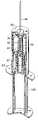
- FIGS. 9A–9Cillustrate a schematic of a prosthesis coating device with a roller embodiment for an applicator upon insertion of the prosthesis into the coating device.
- FIG. 9Aillustrates a 2-D cut-away view
- FIG. 9Billustrates a 3-D cut-away view
- FIG. 9Cillustrates a cross-sectional view of the prosthesis and rollers.
- FIGS. 10A–10Cillustrate a schematic of a prosthesis coating device with a roller embodiment for an applicator during the coating process.
- FIG. 10Aillustrates a 2-D cut-away view
- FIG. 10Billustrates a 3-D cut-away view
- FIG. 10Cillustrates a cross-sectional view of the prosthesis and rollers.
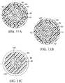
- FIG. 11illustrates a schematic of a prosthesis coating device with a roller embodiment for an applicator
- FIGS. 11A–11Cillustrate different cross-sectional views of the prosthesis coating device.
- FIG. 12illustrates a schematic of a prosthesis coating device of FIG. 11 with a stent and catheter inserted in the device.
- FIG. 13illustrates a flow chart of a method of internal and external coating.
- FIG. 14illustrates a schematic of an internal applicator and mounting for an external coating.
- FIG. 15illustrates a magnified view of the stent in reference to the internal applicator.
- liquid or semi-liquid coating materialscan be applied to a prosthesis using a roller apparatus and method.
- One of the advantages of the rolleris the ability to synchronize velocity of movement between the roller and the prosthesis. Rotation over the surface of the prosthesis provides substantially uniform pressure and/or forces on the prosthesis, for example, by preloaded springs. Control of the amount of coating material applied provides control for the thickness of coating material applied to the prosthesis by the aid of different approaches such as a wiper, control for the level necessary to supply the roller with sufficient coating material, and high consumption of coating material.
- the cylindrical shape of the rollercan provide a single contact line or point.
- FIG. 1illustrates an embodiment where a roller 10 which rotates in the clockwise direction, and a cylindrical prosthesis 14 , for example a stent, which rotates counterclockwise.
- Wiper 18limits the amount of coating material 16 which is transmitted to the surface of prosthesis 14 from reservoir 12 by roller 10 .
- reservoir 12can be replaced with a sponge soaked with coating material 16 .
- the rollercan be modified to minimize length of time to coat the desired surfaces of the prosthesis and utilize a minimum of coating material.
- two or three rollerscan be used to coat the prosthesis.
- the rollerscan move laterally over the surface of the prosthesis or around the prosthesis. Both of these movements of the rollers can be coordinated with movement of the prosthesis.
- the prosthesiscan be positioned inside the roller and coated.
- a hollow cylindrical rollercan be used to coat along its interior circumference. The prosthesis can be placed inside the hollow portion of the cylindrical roller and coated by the movement of the roller and/or movement of the prosthesis.
- FIG. 3illustrates an embodiment with two rollers 10 which are free to rotate either clockwise or counter-clockwise and prosthesis 14 which rotates counter-clockwise.
- the use of two rollers 10decreases the surface area of prosthesis 14 covered by each roller 10 .
- FIG. 5illustrates an embodiment with a hollow roller 50 which rotates counter-clockwise and a prosthesis 14 positioned on the interior of hollow roller 50 . The prosthesis 14 rotates counter-clockwise.
- FIGS. 9A–9Cillustrate a schematic of a prosthesis coating device with a roller embodiment for an applicator upon insertion of the prosthesis into the coating device.
- FIG. 9Aillustrates a 2-D cut-away view
- FIG. 9Billustrates a 3-D cut-away view
- FIG. 9Cillustrates a cross-sectional view of the prosthesis and rollers.
- the prosthesisis a cylindrical stent 99 mounted on a balloon catheter 98 .
- the balloon catheter 98 and stent 99are inserted into static housing 93 until the catheter tip 101 is received in rotor cap 95 .
- the catheter 98 and stent 99are secured into static housing 93 by turning catheter holder 96 .
- three rollers 92are prevented from touching the surface of the stent 99 by elastic arms 102 holding the rollers 92 as illustrated in FIG. 9C .
- the sponge cartridge 97is positioned into sponge holder 94 .
- the sponge holder 94is positioned via pusher 100 into static housing 93 such that it envelops the rollers 92 , stent 99 and catheter tip 101 , and that sponge cartridge 97 overlaps with rollers 92 as illustrated in FIGS. 10A and 10B . This position pushes the rollers 92 radially inward toward the stent 99 causing the rollers 92 to contact the stent 99 as illustrated in FIG. 10C .
- the amount of pressure applied by rollers 92 to stent 99is determined by the shape and elasticity of elastic arms 102 and the elasticity of sponge cartridge 97 .
- Pressurecan be between 1.0 gram per square centimeter to 1.0 kilogram per square centimeter.
- the pressurecan be achieve by spring preloading of the roller to the prosthesis while supporting the prosthesis from its other side (the elastic arms 102 can also have some spring properties so they can preload the prosthesis).
- flexible materialrubber, silicon etc.
- the sponge holder 94is rotated in the static housing 93 and rotor 91 rotates rollers 92 to apply the coating material over the circumference of the stent 99 .
- the coating materialis transferred from the sponge cartridge 97 to the rollers 92 and after half a turn to the surface of stent 99 .
- the coating devicecan be prevented from recoating via a groove in the static housing 93 .
- the roller rotationis caused by the operator of pusher 100 , sponge cartridge 97 slides over screw-type teeth in the rollers 92 and sponge holder 94 that rotate via the linear movement of the sponge cartridge 97 along the static housing 93 .
- the screw-type teeth or screw leadcan provide the sufficient amount of rotation to prevent recoating.
- sponge holder 94can be disconnected from pusher 100 by pulling without rotation.
- linear and rotational movementscan be combined by controlling the linear motion pusher 100 and, thereby, the linear motion of sponge holder 94 into static housing 93 .
- Thiscan be achieved by translating the linear motion of pusher 100 via a screw into a turning motion of sponge holder 94 and rotor 91 .
- the motion of sponge holder 94 , catheter holder 96 , rotor 91 , and pusher 100can be manually and/or mechanically activated and/or controlled.
- FIG. 11illustrates another embodiment of the catheter coating device which shows sponge holder 94 and sponge cartridge 97 .
- Rotor cap 95is positioned within sponge holder 94 and above rollers 92 .
- Sponge holder 94is positioned within static housing 93 .
- Catheter holder 96is positioned within static housing 93 .
- Catheter holder 96has threads 103 B to screw or ratchet into static housing 93 .
- FIG. 11Billustrates a cross-sectional view looking downward based on FIG. 11 at plane 11 B.
- Rotor 91 with elastic arms 102sits on rollers 92 which contact a cylindrical sponge cartridge 97 within sponge holder 94 within static housing 93 .
- FIG. 11Aillustrates a cross-sectional view looking upward based on FIG.
- FIG. 11Cillustrates a cross-sectional view looking upward based on FIG. 11 at plane 11 C.
- Catheter holder 96has radial members that hold the catheter in place while the prosthesis is being coated while both are positioned in the static housing 93 . The catheter is held straight between the radial members 103 A of the catheter holder 96 and the rotor cap 95 .
- FIG. 12illustrates the catheter 98 and prosthesis 99 positioned within catheter holder 96 and static housing 93 .
- the shaft of the catheter 98is held by the radial members 103 A of catheter holder 96 .
- the catheter tip 101is positioned to align with the cavity 105 in rotor cap 95 .
- the catheter tip 101can lock into cavity 105 so that rotor 91 can rotate catheter 98 .
- Static housing 93is static (e.g., in the hand of the operator).
- Sponge cartridge 97rotates (e.g., manually by the operator) with reference to static housing 93 .
- the balloon portion 104 of catheter 98holds prosthesis 99 , in this example, a stent.
- Rollers 92align with the prosthesis 99 and sponge cartridge 97 .
- Rollers 92contact prosthesis 99 without contacting balloon portion 104 .
- liquid or semi-liquid coating materialscan be applied to a prosthesis using a tampon apparatus and method.
- One of the advantages of the tamponare the ability to move over large area of the prosthesis while contacting with the tampon at only certain desired locations to step over large areas where no coating material is going to be applied.
- the tampon movementprovides linear movement to contact the surface of the prosthesis on the upstroke and to absorb coating material on the down stroke and avoids applying shocking forces while contacting the prosthesis such that the coating material adheres to the prosthesis.
- a tamponcan be constructed of silicon, PVC, urethane, chloroprene, etc.
- the shape of the tampon front endis designed to fit the coating application.
- the tamponprovides control over the thickness of coating material applied to the prosthesis via the interaction of tampon and the prosthesis.
- the interaction of coating material delivery to the prosthesisis a function of the prosthesis surface material and surface quality, tampon material end surface quality, coating material properties like density, viscosity, surface tension, and its reaction with tampon and stent material.
- the tamponapproaches perpendicularly flat surfaces of the prosthesis and radially curved surfaces of the prosthesis providing a precise area of contact.
- the tamponprovides the ability to better accommodate irregular surfaces on the prosthesis.
- the tamponcan be more local than the roller so it can accommodate with local irregularities, whereas the roller touches all the stent length, the tampon can come into contact with small portions of the prosthesis.
- FIG. 2illustrates a tampon 20 which moves linearly up and down in the direction of the vertical double arrow, and rotates end-over-end clockwise.
- tampon 20moves down, the surface of tampon 20 proximate to the reservoir 12 absorbs coating material 16 .
- Rotation of the tampon 20makes the surface which absorbed coating material 16 from reservoir 12 distal to the reservoir 12 and proximate to the prosthesis 14 .
- the tampon 20then moves up to contact the prosthesis 14 .
- the prosthesis 14rotates counter-clockwise so that the tampon 20 can contact the portions of the surface of prosthesis 14 which are desired to be coated.
- the tamponcan be used in conjunction with a sponge cartridge soaked with the coating material.
- a sponge cartridge soaked with the coating materialthere is a sponge soaked with the coating material.
- the tamponcontacts the sponge to transfer the coating material to the tampon.
- FIG. 6illustrates an embodiment of a tampon 20 with a sponge cartridge 60 used to apply coating material to prosthesis 14 by a method similar to FIG. 2 .
- several sponge cartridgescan be used in a multi-stage sequence to apply different coating materials.
- coating stagescan include different coating materials such as primer coating, polymer coating and drug coating.
- FIG. 7illustrates an embodiment of a tampon 20 with several sponge cartridges 60 on a tray 70 . Tray 70 can be moved laterally to position tampon 20 such that it contacts different sponge cartridges 60 . This can be done in sequence, e.g., in one direction, or by alternating directions.
- a ribbon stretched between two rollerscan be used to provide a flexible surface which conforms to the prosthesis to apply coating material.
- Other means of contouring a flexible flat surface over the prosthesisare known in the art of contact printing.
- the contact between the rollers and the prosthesisis line contact while the use of ribbon is a surface contact.
- the ribbonhas the same local radius as the prosthesis.
- FIG. 4illustrates an embodiment of an applicator with ribbon 40 and rollers 42 which can rotate the ribbon 40 clockwise. Prosthesis 14 can rotate counter-clockwise. Ribbon 40 can conform to the surface of the prosthesis 14 .
- the device for coatingcan be divided into a non-sterile, non-replaceable portion and a sterile replaceable portion.
- the non-sterile, non-replaceable sectioncomprises user interface and processor which controls servo controller.
- the servo controllercontrols prosthesis stabilizer and motion driver, coating material changer, and roller or tampon driver.
- the sterile replaceable portioncomprises prosthesis clamp, coating material reservoirs, and roller sub-assemblies or tampon.
- both portionscan be mounted on a single base.
- the prosthesis stabilizer and motion driverdrives the prosthesis clamp
- the coating material changerdrives the coating material reservoirs
- the roller or tampon driverdrives the roller sub-assemblies or tampon.
- the interfacesare both electrical and mechanical.
- FIG. 8is a block diagram of an embodiment of the prosthesis coating device of the present invention showing a non-sterile non-replaceable section 80 and a sterile replaceable section 82 .
- Section 80is permanently mounted on base 84 and section 82 is removably mounted on base 84 .
- Section 80comprises a processor and user interface 86 .
- the user interfaceis a man-machine interface or MMI which can include software and manual/mechanical interface.
- Servo controller 90activates prosthesis stabilizer and rotation driver 106 , coating material changer 108 , applicator driver 112 .
- An example of a coating material changeris tray 70 in FIG. 7 .
- Prosthesis stabilizer and rotation driver 106drives the prosthesis clamp 110 which holds prosthesis 14 .
- Coating material changer 108drives coating material reservoirs 114 .
- An example of coating material reservoirsare sponge cartridges 60 in FIG. 7 .
- Applicator driver 112drives applicator 88 .
- FIG. 13illustrates a flow chart for a method for a two stage coating process for a stent.
- FIG. 14illustrates a device for internal and external coating. The process begins at start 200 by gripping the stent 300 (not shown) and driving it in the direction of the arrow over the internal coating head 310 .
- the internal coating step 210coats the interior surface of the stent by continuing the movement of the stent 300 in the direction of the arrow over the internal coating head 310 .
- the interior surfacerefers to the surface that contacts the balloon catheter prior to insertion into the body and is exposed to the blood flow after expansion and contraction of the balloon catheter after insertion into the body.
- the stent 300is then positioned on the external-coating mounting 320 .
- the external coating step 220coats the exterior surface of the stent 300 according to the roller and tampon embodiments described above.
- the exterior surfacerefers to the surface that is covered by the exterior lumen of a dual lumen catheter prior to insertion into the body and is in contact with the interior surface of the blood vessel after expansion of the balloon catheter after insertion into the body.
- the verification step 230inspects the stent 300 for coating flaws using a scanning process which is described in copending application by inventors Avraham Shekalim and Ascher Shmulewitz, Ser. No. 10/210,714, entitled “STENT COATING DEVICE,” filed on Jul. 30, 2002, which is hereby incorporated in its entirety herein by reference and is commonly owned by the same assignee of this application.
- the unloading step 240removes the stent 300 from the external-coating mounting 320 .
- FIG. 15illustrates a magnified stent coating device for coating the interior surface of a stent.
- Stent 300is translated over internal coating head 310 .
- Internal coating head 310comprises an internal coating cup 340 which can be made of any synthetic material such as rubber or silicone adapted to evenly distribute the coating material on its surface.
- the coating material 350flows up cup support pipe 330 to internal coating cup 340 where the coating material flows evenly over the top surface 380 of the internal coating cup 340 to its edges 360 which contact the interior surface 370 of the stent 300 .
Landscapes
- Health & Medical Sciences (AREA)
- Life Sciences & Earth Sciences (AREA)
- Public Health (AREA)
- Veterinary Medicine (AREA)
- Epidemiology (AREA)
- Surgery (AREA)
- Animal Behavior & Ethology (AREA)
- General Health & Medical Sciences (AREA)
- Heart & Thoracic Surgery (AREA)
- Vascular Medicine (AREA)
- Chemical & Material Sciences (AREA)
- Engineering & Computer Science (AREA)
- Biomedical Technology (AREA)
- Medicinal Chemistry (AREA)
- Molecular Biology (AREA)
- Materials For Medical Uses (AREA)
- Media Introduction/Drainage Providing Device (AREA)
- Absorbent Articles And Supports Therefor (AREA)
Abstract
Description
Claims (10)
Priority Applications (5)
| Application Number | Priority Date | Filing Date | Title |
|---|---|---|---|
| US10/256,755US6971813B2 (en) | 2002-09-27 | 2002-09-27 | Contact coating of prostheses |
| PCT/IB2003/004844WO2004028579A2 (en) | 2002-09-27 | 2003-09-26 | Contact coating of prostheses |
| AU2003274508AAU2003274508A1 (en) | 2002-09-27 | 2003-09-26 | Contact coating of prostheses |
| US11/292,435US7344599B2 (en) | 2002-09-27 | 2005-12-02 | Contact coating of prostheses |
| US12/031,407US9272307B2 (en) | 2002-09-27 | 2008-02-14 | Contact coating of prostheses |
Applications Claiming Priority (1)
| Application Number | Priority Date | Filing Date | Title |
|---|---|---|---|
| US10/256,755US6971813B2 (en) | 2002-09-27 | 2002-09-27 | Contact coating of prostheses |
Related Child Applications (1)
| Application Number | Title | Priority Date | Filing Date |
|---|---|---|---|
| US11/292,435ContinuationUS7344599B2 (en) | 2002-09-27 | 2005-12-02 | Contact coating of prostheses |
Publications (2)
| Publication Number | Publication Date |
|---|---|
| US20040062592A1 US20040062592A1 (en) | 2004-04-01 |
| US6971813B2true US6971813B2 (en) | 2005-12-06 |
Family
ID=32029345
Family Applications (3)
| Application Number | Title | Priority Date | Filing Date |
|---|---|---|---|
| US10/256,755Expired - LifetimeUS6971813B2 (en) | 2002-09-27 | 2002-09-27 | Contact coating of prostheses |
| US11/292,435Expired - Fee RelatedUS7344599B2 (en) | 2002-09-27 | 2005-12-02 | Contact coating of prostheses |
| US12/031,407Expired - Fee RelatedUS9272307B2 (en) | 2002-09-27 | 2008-02-14 | Contact coating of prostheses |
Family Applications After (2)
| Application Number | Title | Priority Date | Filing Date |
|---|---|---|---|
| US11/292,435Expired - Fee RelatedUS7344599B2 (en) | 2002-09-27 | 2005-12-02 | Contact coating of prostheses |
| US12/031,407Expired - Fee RelatedUS9272307B2 (en) | 2002-09-27 | 2008-02-14 | Contact coating of prostheses |
Country Status (3)
| Country | Link |
|---|---|
| US (3) | US6971813B2 (en) |
| AU (1) | AU2003274508A1 (en) |
| WO (1) | WO2004028579A2 (en) |
Cited By (71)
| Publication number | Priority date | Publication date | Assignee | Title |
|---|---|---|---|---|
| US20050015142A1 (en)* | 2003-03-10 | 2005-01-20 | Michael Austin | Coated medical device and method for manufacturing the same |
| US20050049694A1 (en)* | 2003-08-07 | 2005-03-03 | Medtronic Ave. | Extrusion process for coating stents |
| US20050100655A1 (en)* | 2001-07-02 | 2005-05-12 | Sheng-Ping Zhong | Coating dispensing system and method using a solenoid head for coating medical devices |
| US20060110209A1 (en)* | 2002-09-27 | 2006-05-25 | Labcoat, Ltd. | Contact coating of prostheses |
| US20060240065A1 (en)* | 2005-04-26 | 2006-10-26 | Yung-Ming Chen | Compositions for medical devices containing agent combinations in controlled volumes |
| US20070233246A1 (en)* | 2006-03-31 | 2007-10-04 | Sdgi Holdings, Inc. | Spinal implants with improved mechanical response |
| US20070259125A1 (en)* | 2006-05-02 | 2007-11-08 | Boston Scientific Scimed, Inc. | Partially roll coated workpiece and methods and systems for making the same |
| US20070270970A1 (en)* | 2006-03-14 | 2007-11-22 | Sdgi Holdings, Inc. | Spinal implants with improved wear resistance |
| US20070280986A1 (en)* | 2006-06-01 | 2007-12-06 | Carlos Gil | Intra-operative coating of implants |
| US20080071355A1 (en)* | 2006-09-14 | 2008-03-20 | Boston Scientific Scimed, Inc. | Medical Devices with Drug-Eluting Coating |
| US7361138B2 (en)* | 2003-07-31 | 2008-04-22 | Scimed Life Systems, Inc. | Bioabsorbable casing for surgical sling assembly |
| US20090123516A1 (en)* | 2005-08-08 | 2009-05-14 | The Board Of Regents Of The University Of Texas System | Drug delivery from implants using self-assembled monolayers-therapeutic sams |
| US7563324B1 (en)* | 2003-12-29 | 2009-07-21 | Advanced Cardiovascular Systems Inc. | System and method for coating an implantable medical device |
| US7704544B2 (en)* | 2003-10-07 | 2010-04-27 | Advanced Cardiovascular Systems, Inc. | System and method for coating a tubular implantable medical device |
| US20100160961A1 (en)* | 2008-12-22 | 2010-06-24 | Ethicon, Inc. | Surgical sutures having collapsible tissue anchoring protrusions and methods therefor |
| US7743727B2 (en) | 2003-08-04 | 2010-06-29 | Boston Scientific Scimed, Inc. | Stent coating apparatus and method |
| US7775178B2 (en) | 2006-05-26 | 2010-08-17 | Advanced Cardiovascular Systems, Inc. | Stent coating apparatus and method |
| US20100300356A1 (en)* | 2005-01-31 | 2010-12-02 | Boston Scientific Scimed, Inc. | Method and System for Coating a Medical Device Using Optical Drop Volume Verification |
| US20110045034A1 (en)* | 2008-03-03 | 2011-02-24 | Israel Nur | Gelatin Sponge Comprising an Active Ingredient, Its Preparation and Use |
| US7931683B2 (en) | 2007-07-27 | 2011-04-26 | Boston Scientific Scimed, Inc. | Articles having ceramic coated surfaces |
| US7938855B2 (en) | 2007-11-02 | 2011-05-10 | Boston Scientific Scimed, Inc. | Deformable underlayer for stent |
| US7942926B2 (en) | 2007-07-11 | 2011-05-17 | Boston Scientific Scimed, Inc. | Endoprosthesis coating |
| US20110117266A1 (en)* | 2009-07-20 | 2011-05-19 | Boston Scientific Scimed, Inc. | Medical Device Coating System |
| US7976915B2 (en) | 2007-05-23 | 2011-07-12 | Boston Scientific Scimed, Inc. | Endoprosthesis with select ceramic morphology |
| US7976891B1 (en) | 2005-12-16 | 2011-07-12 | Advanced Cardiovascular Systems, Inc. | Abluminal stent coating apparatus and method of using focused acoustic energy |
| US7981150B2 (en) | 2006-11-09 | 2011-07-19 | Boston Scientific Scimed, Inc. | Endoprosthesis with coatings |
| US7985252B2 (en) | 2008-07-30 | 2011-07-26 | Boston Scientific Scimed, Inc. | Bioerodible endoprosthesis |
| US7998192B2 (en) | 2008-05-09 | 2011-08-16 | Boston Scientific Scimed, Inc. | Endoprostheses |
| US8002821B2 (en) | 2006-09-18 | 2011-08-23 | Boston Scientific Scimed, Inc. | Bioerodible metallic ENDOPROSTHESES |
| US8002823B2 (en) | 2007-07-11 | 2011-08-23 | Boston Scientific Scimed, Inc. | Endoprosthesis coating |
| US8029554B2 (en) | 2007-11-02 | 2011-10-04 | Boston Scientific Scimed, Inc. | Stent with embedded material |
| US8048150B2 (en) | 2006-04-12 | 2011-11-01 | Boston Scientific Scimed, Inc. | Endoprosthesis having a fiber meshwork disposed thereon |
| US8052744B2 (en) | 2006-09-15 | 2011-11-08 | Boston Scientific Scimed, Inc. | Medical devices and methods of making the same |
| US8052745B2 (en) | 2007-09-13 | 2011-11-08 | Boston Scientific Scimed, Inc. | Endoprosthesis |
| US8052743B2 (en) | 2006-08-02 | 2011-11-08 | Boston Scientific Scimed, Inc. | Endoprosthesis with three-dimensional disintegration control |
| US8057534B2 (en) | 2006-09-15 | 2011-11-15 | Boston Scientific Scimed, Inc. | Bioerodible endoprostheses and methods of making the same |
| US8067054B2 (en) | 2007-04-05 | 2011-11-29 | Boston Scientific Scimed, Inc. | Stents with ceramic drug reservoir layer and methods of making and using the same |
| US8066763B2 (en) | 1998-04-11 | 2011-11-29 | Boston Scientific Scimed, Inc. | Drug-releasing stent with ceramic-containing layer |
| US8070797B2 (en) | 2007-03-01 | 2011-12-06 | Boston Scientific Scimed, Inc. | Medical device with a porous surface for delivery of a therapeutic agent |
| US8071156B2 (en) | 2009-03-04 | 2011-12-06 | Boston Scientific Scimed, Inc. | Endoprostheses |
| US8080055B2 (en) | 2006-12-28 | 2011-12-20 | Boston Scientific Scimed, Inc. | Bioerodible endoprostheses and methods of making the same |
| US8089029B2 (en) | 2006-02-01 | 2012-01-03 | Boston Scientific Scimed, Inc. | Bioabsorbable metal medical device and method of manufacture |
| US8128689B2 (en) | 2006-09-15 | 2012-03-06 | Boston Scientific Scimed, Inc. | Bioerodible endoprosthesis with biostable inorganic layers |
| US8137397B2 (en)* | 2004-02-26 | 2012-03-20 | Boston Scientific Scimed, Inc. | Medical devices |
| US8187620B2 (en) | 2006-03-27 | 2012-05-29 | Boston Scientific Scimed, Inc. | Medical devices comprising a porous metal oxide or metal material and a polymer coating for delivering therapeutic agents |
| US8216632B2 (en) | 2007-11-02 | 2012-07-10 | Boston Scientific Scimed, Inc. | Endoprosthesis coating |
| US8221822B2 (en) | 2007-07-31 | 2012-07-17 | Boston Scientific Scimed, Inc. | Medical device coating by laser cladding |
| US8231980B2 (en) | 2008-12-03 | 2012-07-31 | Boston Scientific Scimed, Inc. | Medical implants including iridium oxide |
| US8236046B2 (en) | 2008-06-10 | 2012-08-07 | Boston Scientific Scimed, Inc. | Bioerodible endoprosthesis |
| US8267992B2 (en) | 2009-03-02 | 2012-09-18 | Boston Scientific Scimed, Inc. | Self-buffering medical implants |
| US8287937B2 (en) | 2009-04-24 | 2012-10-16 | Boston Scientific Scimed, Inc. | Endoprosthese |
| US8303643B2 (en) | 2001-06-27 | 2012-11-06 | Remon Medical Technologies Ltd. | Method and device for electrochemical formation of therapeutic species in vivo |
| US8313760B2 (en) | 2002-05-24 | 2012-11-20 | Angiotech International Ag | Compositions and methods for coating medical implants |
| US8372420B2 (en) | 2002-05-24 | 2013-02-12 | Angiotech International Ag | Compositions and methods for coating medical implants |
| US8382824B2 (en) | 2008-10-03 | 2013-02-26 | Boston Scientific Scimed, Inc. | Medical implant having NANO-crystal grains with barrier layers of metal nitrides or fluorides |
| US8431149B2 (en) | 2007-03-01 | 2013-04-30 | Boston Scientific Scimed, Inc. | Coated medical devices for abluminal drug delivery |
| US8449603B2 (en) | 2008-06-18 | 2013-05-28 | Boston Scientific Scimed, Inc. | Endoprosthesis coating |
| US8574615B2 (en) | 2006-03-24 | 2013-11-05 | Boston Scientific Scimed, Inc. | Medical devices having nanoporous coatings for controlled therapeutic agent delivery |
| US8597720B2 (en) | 2007-01-21 | 2013-12-03 | Hemoteq Ag | Medical product for treating stenosis of body passages and for preventing threatening restenosis |
| US8668732B2 (en) | 2010-03-23 | 2014-03-11 | Boston Scientific Scimed, Inc. | Surface treated bioerodible metal endoprostheses |
| US8771343B2 (en) | 2006-06-29 | 2014-07-08 | Boston Scientific Scimed, Inc. | Medical devices with selective titanium oxide coatings |
| US8808726B2 (en) | 2006-09-15 | 2014-08-19 | Boston Scientific Scimed. Inc. | Bioerodible endoprostheses and methods of making the same |
| US8815273B2 (en) | 2007-07-27 | 2014-08-26 | Boston Scientific Scimed, Inc. | Drug eluting medical devices having porous layers |
| US8815275B2 (en) | 2006-06-28 | 2014-08-26 | Boston Scientific Scimed, Inc. | Coatings for medical devices comprising a therapeutic agent and a metallic material |
| US8840660B2 (en) | 2006-01-05 | 2014-09-23 | Boston Scientific Scimed, Inc. | Bioerodible endoprostheses and methods of making the same |
| US8900292B2 (en) | 2007-08-03 | 2014-12-02 | Boston Scientific Scimed, Inc. | Coating for medical device having increased surface area |
| US8920491B2 (en) | 2008-04-22 | 2014-12-30 | Boston Scientific Scimed, Inc. | Medical devices having a coating of inorganic material |
| US8932346B2 (en) | 2008-04-24 | 2015-01-13 | Boston Scientific Scimed, Inc. | Medical devices having inorganic particle layers |
| US20150231362A1 (en)* | 2012-08-23 | 2015-08-20 | Cardionovum Gmbh | Balloon surface coating for valvuloplasty |
| US9284409B2 (en) | 2007-07-19 | 2016-03-15 | Boston Scientific Scimed, Inc. | Endoprosthesis having a non-fouling surface |
| US20160250382A1 (en)* | 2013-10-29 | 2016-09-01 | The University Of Akron | Resorbable, amino acid-based poly(ester urea)s scaffold for vascular graft tissue engineering |
Families Citing this family (44)
| Publication number | Priority date | Publication date | Assignee | Title |
|---|---|---|---|---|
| US7125577B2 (en) | 2002-09-27 | 2006-10-24 | Surmodics, Inc | Method and apparatus for coating of substrates |
| USRE40722E1 (en) | 2002-09-27 | 2009-06-09 | Surmodics, Inc. | Method and apparatus for coating of substrates |
| US7192484B2 (en) | 2002-09-27 | 2007-03-20 | Surmodics, Inc. | Advanced coating apparatus and method |
| US20040236416A1 (en)* | 2003-05-20 | 2004-11-25 | Robert Falotico | Increased biocompatibility of implantable medical devices |
| US7585369B2 (en)* | 2004-08-04 | 2009-09-08 | Larson Marian L | Apparatus for coating medical devices |
| US7958840B2 (en)* | 2004-10-27 | 2011-06-14 | Surmodics, Inc. | Method and apparatus for coating of substrates |
| US8800439B2 (en)* | 2006-08-16 | 2014-08-12 | Lloyd Douglas Clark | Continuously updatable rotary pad printing apparatus and method |
| CA2671437A1 (en)* | 2006-10-31 | 2008-05-29 | University Of Rochester | Targeted delivery of therapeutic agents with lyophilized matrices |
| US8231929B2 (en)* | 2006-11-09 | 2012-07-31 | Cook Medical Technologies Llc | Medical device coating process |
| US8147899B2 (en)* | 2007-05-08 | 2012-04-03 | Boston Scientific Scimed, Inc. | Methods and systems for depositing coating on a medical device |
| DE102007034364A1 (en)* | 2007-07-24 | 2009-01-29 | Biotronik Vi Patent Ag | Degradable metal stent with active ingredient-containing coating |
| US9364349B2 (en) | 2008-04-24 | 2016-06-14 | Surmodics, Inc. | Coating application system with shaped mandrel |
| US9295820B2 (en) | 2008-08-14 | 2016-03-29 | Surmodics, Inc. | Method and apparatus for coating balloon catheters |
| WO2010024882A1 (en)* | 2008-08-28 | 2010-03-04 | Cook Incorporated | Coated stent |
| US8049061B2 (en) | 2008-09-25 | 2011-11-01 | Abbott Cardiovascular Systems, Inc. | Expandable member formed of a fibrous matrix having hydrogel polymer for intraluminal drug delivery |
| US8076529B2 (en) | 2008-09-26 | 2011-12-13 | Abbott Cardiovascular Systems, Inc. | Expandable member formed of a fibrous matrix for intraluminal drug delivery |
| US8226603B2 (en) | 2008-09-25 | 2012-07-24 | Abbott Cardiovascular Systems Inc. | Expandable member having a covering formed of a fibrous matrix for intraluminal drug delivery |
| CN102264426A (en)* | 2008-12-22 | 2011-11-30 | 皇家飞利浦电子股份有限公司 | Respiratory interface devices including mechanisms for manipulating nasal bridge pressure |
| WO2011119536A1 (en) | 2010-03-22 | 2011-09-29 | Abbott Cardiovascular Systems Inc. | Stent delivery system having a fibrous matrix covering with improved stent retention |
| DE102010055562B4 (en)* | 2010-12-23 | 2015-07-09 | Heraeus Medical Gmbh | Coating device and coating method |
| DE102010055560B4 (en)* | 2010-12-23 | 2017-02-23 | Heraeus Medical Gmbh | coater |
| DE102010055561B4 (en)* | 2010-12-23 | 2015-12-31 | Heraeus Medical Gmbh | Coating method and coating device |
| DE102010055559B4 (en)* | 2010-12-23 | 2015-10-29 | Heraeus Medical Gmbh | Coating method and coating device |
| US9585746B2 (en) | 2011-07-29 | 2017-03-07 | Carnegie Mellon University | Artificial valved conduits for cardiac reconstructive procedures and methods for their production |
| DE102011117526B4 (en)* | 2011-11-03 | 2015-07-30 | Heraeus Medical Gmbh | Coating method and coating device for medical implants |
| JP6549482B2 (en) | 2012-06-01 | 2019-07-24 | サーモディクス,インコーポレイテッド | Device and method for coating a balloon catheter |
| US9827401B2 (en) | 2012-06-01 | 2017-11-28 | Surmodics, Inc. | Apparatus and methods for coating medical devices |
| US11090468B2 (en)* | 2012-10-25 | 2021-08-17 | Surmodics, Inc. | Apparatus and methods for coating medical devices |
| US9283350B2 (en) | 2012-12-07 | 2016-03-15 | Surmodics, Inc. | Coating apparatus and methods |
| US9750928B2 (en) | 2013-02-13 | 2017-09-05 | Becton, Dickinson And Company | Blood control IV catheter with stationary septum activator |
| EP2964153B1 (en) | 2013-03-08 | 2022-08-31 | Carnegie Mellon University | Expandable implantable conduit |
| DE102013014821A1 (en)* | 2013-09-10 | 2015-03-12 | Alexander Rübben | Gefäßendoprothesenbeschichtung |
| US9459193B2 (en)* | 2013-12-18 | 2016-10-04 | Abbott Cardiovascular Systems Inc. | Stent holder having a reduced profile |
| US10376686B2 (en) | 2014-04-23 | 2019-08-13 | Becton, Dickinson And Company | Antimicrobial caps for medical connectors |
| US9675793B2 (en) | 2014-04-23 | 2017-06-13 | Becton, Dickinson And Company | Catheter tubing with extraluminal antimicrobial coating |
| US9789279B2 (en) | 2014-04-23 | 2017-10-17 | Becton, Dickinson And Company | Antimicrobial obturator for use with vascular access devices |
| US10232088B2 (en) | 2014-07-08 | 2019-03-19 | Becton, Dickinson And Company | Antimicrobial coating forming kink resistant feature on a vascular access device |
| US10493244B2 (en) | 2015-10-28 | 2019-12-03 | Becton, Dickinson And Company | Extension tubing strain relief |
| GB2552834A (en)* | 2016-08-12 | 2018-02-14 | Vestas Wind Sys As | Method and apparatus for applying a layer of material to a leading edge of a wind turbine blade |
| GB2552833A (en)* | 2016-08-12 | 2018-02-14 | Vestas Wind Sys As | Method and apparatus for applying a layer of material to a leading edge of a wind turbine blade |
| WO2017151900A1 (en)* | 2016-03-02 | 2017-09-08 | Peca Labs, Inc. | Expandable implantable conduit |
| EP4397276A3 (en) | 2016-10-10 | 2024-09-18 | Peca Labs, Inc. | Transcatheter stent and valve assembly |
| US11628466B2 (en) | 2018-11-29 | 2023-04-18 | Surmodics, Inc. | Apparatus and methods for coating medical devices |
| US11819590B2 (en) | 2019-05-13 | 2023-11-21 | Surmodics, Inc. | Apparatus and methods for coating medical devices |
Citations (11)
| Publication number | Priority date | Publication date | Assignee | Title |
|---|---|---|---|---|
| US2464040A (en)* | 1945-01-23 | 1949-03-08 | William C Huebner | Dampening or moistening roller |
| US5298276A (en)* | 1990-08-24 | 1994-03-29 | Swaminathan Jayaraman | Process for producing artificial blood vessels of controlled permeability and product produced thereby |
| US5763330A (en) | 1995-09-29 | 1998-06-09 | Highland Industries, Inc. | Extrusion coated fabric |
| US5773081A (en) | 1995-07-31 | 1998-06-30 | Becton Dickinson And Company | Method for coating of objects using a rotating resilient matrix |
| US5925259A (en) | 1995-08-04 | 1999-07-20 | International Business Machines Corporation | Lithographic surface or thin layer modification |
| US6190077B1 (en)* | 1997-03-24 | 2001-02-20 | Green Management Limited | Apparatus for the selective application of liquid media |
| WO2002014078A2 (en) | 2000-08-14 | 2002-02-21 | Surface Logix, Inc. | Deformable stamp for patterning three-dimensional surfaces |
| US6352768B1 (en) | 1999-03-02 | 2002-03-05 | Avery Dennison Corporation | Printable release coatings and stamp constructions |
| US6355058B1 (en)* | 1999-12-30 | 2002-03-12 | Advanced Cardiovascular Systems, Inc. | Stent with radiopaque coating consisting of particles in a binder |
| US6413318B2 (en) | 2000-02-25 | 2002-07-02 | Samsung Electronics Co., Ltd. | Sheet coating apparatus |
| US6428853B1 (en) | 1994-12-22 | 2002-08-06 | Btg Källe Inventing Ab | Coating device and process for coating |
Family Cites Families (13)
| Publication number | Priority date | Publication date | Assignee | Title |
|---|---|---|---|---|
| US2426040A (en)* | 1944-03-10 | 1947-08-19 | George L Miller | Check valve |
| GB1280021A (en)* | 1968-07-26 | 1972-07-05 | Denys Fisher Toys Ltd | A method of and apparatus for drawing designs |
| US5634946A (en)* | 1988-08-24 | 1997-06-03 | Focal, Inc. | Polymeric endoluminal paving process |
| DE69317548T2 (en)* | 1993-04-23 | 1998-08-13 | Schneider (Europe) Gmbh, Buelach | Stent with a coating of elastic material and method for applying the coating on the stent |
| US5558900A (en)* | 1994-09-22 | 1996-09-24 | Fan; You-Ling | One-step thromboresistant, lubricious coating |
| US5931851A (en)* | 1998-04-21 | 1999-08-03 | Advanced Cardiovascular Systems, Inc. | Method and apparatus for rubber-tube crimping tool with premount stent |
| US6475644B1 (en)* | 1998-11-18 | 2002-11-05 | Radiovascular Systems, L.L.C. | Radioactive coating solutions methods, and substrates |
| MXPA01007651A (en)* | 1999-01-28 | 2002-03-14 | Union Carbide Chem Plastic | Lubricious medical devices. |
| WO2000057818A1 (en)* | 1999-03-29 | 2000-10-05 | Cardio Synopsis Inc. | Stent with an integrated film coating for deployment throughout the body |
| US6395326B1 (en)* | 2000-05-31 | 2002-05-28 | Advanced Cardiovascular Systems, Inc. | Apparatus and method for depositing a coating onto a surface of a prosthesis |
| US6824559B2 (en)* | 2000-12-22 | 2004-11-30 | Advanced Cardiovascular Systems, Inc. | Ethylene-carboxyl copolymers as drug delivery matrices |
| US6939376B2 (en)* | 2001-11-05 | 2005-09-06 | Sun Biomedical, Ltd. | Drug-delivery endovascular stent and method for treating restenosis |
| US6971813B2 (en)* | 2002-09-27 | 2005-12-06 | Labcoat, Ltd. | Contact coating of prostheses |
- 2002
- 2002-09-27USUS10/256,755patent/US6971813B2/ennot_activeExpired - Lifetime
- 2003
- 2003-09-26WOPCT/IB2003/004844patent/WO2004028579A2/ennot_activeApplication Discontinuation
- 2003-09-26AUAU2003274508Apatent/AU2003274508A1/ennot_activeAbandoned
- 2005
- 2005-12-02USUS11/292,435patent/US7344599B2/ennot_activeExpired - Fee Related
- 2008
- 2008-02-14USUS12/031,407patent/US9272307B2/ennot_activeExpired - Fee Related
Patent Citations (11)
| Publication number | Priority date | Publication date | Assignee | Title |
|---|---|---|---|---|
| US2464040A (en)* | 1945-01-23 | 1949-03-08 | William C Huebner | Dampening or moistening roller |
| US5298276A (en)* | 1990-08-24 | 1994-03-29 | Swaminathan Jayaraman | Process for producing artificial blood vessels of controlled permeability and product produced thereby |
| US6428853B1 (en) | 1994-12-22 | 2002-08-06 | Btg Källe Inventing Ab | Coating device and process for coating |
| US5773081A (en) | 1995-07-31 | 1998-06-30 | Becton Dickinson And Company | Method for coating of objects using a rotating resilient matrix |
| US5925259A (en) | 1995-08-04 | 1999-07-20 | International Business Machines Corporation | Lithographic surface or thin layer modification |
| US5763330A (en) | 1995-09-29 | 1998-06-09 | Highland Industries, Inc. | Extrusion coated fabric |
| US6190077B1 (en)* | 1997-03-24 | 2001-02-20 | Green Management Limited | Apparatus for the selective application of liquid media |
| US6352768B1 (en) | 1999-03-02 | 2002-03-05 | Avery Dennison Corporation | Printable release coatings and stamp constructions |
| US6355058B1 (en)* | 1999-12-30 | 2002-03-12 | Advanced Cardiovascular Systems, Inc. | Stent with radiopaque coating consisting of particles in a binder |
| US6413318B2 (en) | 2000-02-25 | 2002-07-02 | Samsung Electronics Co., Ltd. | Sheet coating apparatus |
| WO2002014078A2 (en) | 2000-08-14 | 2002-02-21 | Surface Logix, Inc. | Deformable stamp for patterning three-dimensional surfaces |
Non-Patent Citations (10)
| Title |
|---|
| "Basic Theory: How does transfer pad printing work?," http://www.itwtranstech.com/pages/how.html, Trans Tech America Inc., 2002. |
| Adler, L.M., et al., "Analysis of exposure times and dose escalation of paclitaxel in ovarian cancer cell lines," Cancer 74(7):1891-1898, Abstract only, 1994. |
| Farb, Andrew, "Comparative Pathology of Drug Eluting Stents: Insights Into Effectiveness and Toxicity from the Animal Lab," Presentation from CRF Drug-Eluting Stent Symposium, http://tctmd.com/expert-presentations, 2002. |
| Hiatt, Bonnie L. et al., "Drug-Eluting Stents for Prevention of Restenosis: In Quest for the Holy Grail," Catheterization and Cardiovascular Interventions 55:409-417, 2002. |
| Kalinowski, M., et al., "Paclitaxel inhibits proliferation of cell lines responsible for metal stent obstruction: Possible topical application in malignant bile duct obstructions," Invest Radiol 37(7):399-404, Abstract only, 2002. |
| Kandzari, David E., et al., "Highlights from the American Heart Association Annual Scientific Sessions 2001: Nov. 11-14, 2001," American Heart Journal 143(2):217-228, 2002. |
| Liebmann, J.E., et al., "Cytotoxic studies of paclitaxel (Taxol) in human tumor cell lines," Br J Cancer 68(6):1104-1109, Abstract only, 1993. |
| Regar, E., et al., "Stent development and local drug delivery,"Br Med Bull 59:227-248, Abstract only, 2001. |
| Sirolimus: Pre-clinical studies-Evaluatin of dosing, efficacy and toxicity. Andrew J. and Carter D.O., TCT Sep. 2001. |
| Taxol Quanam Data and the SCORE study, Grube E. (the effect of taxol on the edges of the stent and dose response screening) 6-7. ISET 2002 Miami Beach, Mar. 19-23, 2002. |
Cited By (106)
| Publication number | Priority date | Publication date | Assignee | Title |
|---|---|---|---|---|
| US8066763B2 (en) | 1998-04-11 | 2011-11-29 | Boston Scientific Scimed, Inc. | Drug-releasing stent with ceramic-containing layer |
| US8303643B2 (en) | 2001-06-27 | 2012-11-06 | Remon Medical Technologies Ltd. | Method and device for electrochemical formation of therapeutic species in vivo |
| US20050100655A1 (en)* | 2001-07-02 | 2005-05-12 | Sheng-Ping Zhong | Coating dispensing system and method using a solenoid head for coating medical devices |
| US7563474B2 (en) | 2001-07-02 | 2009-07-21 | Boston Scientific Scimed, Inc. | Method of coating with selectively activated dispensing head |
| US20090226601A1 (en)* | 2001-07-02 | 2009-09-10 | Boston Scientific Scimed, Inc. | Coating dispensing system and method using a solenoid head for coating medical devices |
| US7785652B2 (en) | 2001-07-02 | 2010-08-31 | Boston Scientific Scimed, Inc. | Coating dispensing system and method using a solenoid head for coating medical devices |
| US8425927B2 (en) | 2002-05-24 | 2013-04-23 | Angiotech International Ag | Compositions and methods for coating medical implants |
| US8372420B2 (en) | 2002-05-24 | 2013-02-12 | Angiotech International Ag | Compositions and methods for coating medical implants |
| US8313760B2 (en) | 2002-05-24 | 2012-11-20 | Angiotech International Ag | Compositions and methods for coating medical implants |
| US20080206442A1 (en)* | 2002-09-27 | 2008-08-28 | Labcoat, Ltd. | Contact coating of prostheses |
| US9272307B2 (en) | 2002-09-27 | 2016-03-01 | Boston Scientific Scimed, Inc. | Contact coating of prostheses |
| US7344599B2 (en)* | 2002-09-27 | 2008-03-18 | Labcoat, Ltd. | Contact coating of prostheses |
| US20060110209A1 (en)* | 2002-09-27 | 2006-05-25 | Labcoat, Ltd. | Contact coating of prostheses |
| US20050015142A1 (en)* | 2003-03-10 | 2005-01-20 | Michael Austin | Coated medical device and method for manufacturing the same |
| US8281737B2 (en)* | 2003-03-10 | 2012-10-09 | Boston Scientific Scimed, Inc. | Coated medical device and method for manufacturing the same |
| US7824326B2 (en)* | 2003-07-31 | 2010-11-02 | Boston Scientific Scimed, Inc. | Bioabsorbable casing for surgical sling assembly |
| US7361138B2 (en)* | 2003-07-31 | 2008-04-22 | Scimed Life Systems, Inc. | Bioabsorbable casing for surgical sling assembly |
| US8359998B2 (en) | 2003-08-04 | 2013-01-29 | Boston Scientific Scimed Inc. | Stent coating apparatus and method |
| US20100242840A1 (en)* | 2003-08-04 | 2010-09-30 | Boston Scientific Scimed, Inc. | Stent Coating Apparatus and Method |
| US7743727B2 (en) | 2003-08-04 | 2010-06-29 | Boston Scientific Scimed, Inc. | Stent coating apparatus and method |
| US7318944B2 (en)* | 2003-08-07 | 2008-01-15 | Medtronic Vascular, Inc. | Extrusion process for coating stents |
| US8128982B2 (en) | 2003-08-07 | 2012-03-06 | Medtronic Vascular, Inc | Extrusion process for coating stents |
| US20080071360A1 (en)* | 2003-08-07 | 2008-03-20 | Medtronic Vascular, Inc. | Extrusion Process for Coating Stents |
| US20050049694A1 (en)* | 2003-08-07 | 2005-03-03 | Medtronic Ave. | Extrusion process for coating stents |
| US7704544B2 (en)* | 2003-10-07 | 2010-04-27 | Advanced Cardiovascular Systems, Inc. | System and method for coating a tubular implantable medical device |
| US20100154705A1 (en)* | 2003-10-07 | 2010-06-24 | Pacetti Stephen D | System for Coating a Tubular Implantable Medical Device |
| US20090238949A1 (en)* | 2003-12-29 | 2009-09-24 | Advanced Cardiovascular Systems Inc. | Methods For Coating Implantable Medical Devices |
| US8057844B2 (en)* | 2003-12-29 | 2011-11-15 | Advanced Cardiovascular Systems, Inc. | Methods for coating implantable medical devices |
| US7563324B1 (en)* | 2003-12-29 | 2009-07-21 | Advanced Cardiovascular Systems Inc. | System and method for coating an implantable medical device |
| US8137397B2 (en)* | 2004-02-26 | 2012-03-20 | Boston Scientific Scimed, Inc. | Medical devices |
| US8739727B2 (en) | 2004-03-09 | 2014-06-03 | Boston Scientific Scimed, Inc. | Coated medical device and method for manufacturing the same |
| US8381676B2 (en) | 2005-01-31 | 2013-02-26 | Boston Scientific Scimed, Inc. | Method and system for coating a medical device using optical drop volume verification |
| US20100300356A1 (en)* | 2005-01-31 | 2010-12-02 | Boston Scientific Scimed, Inc. | Method and System for Coating a Medical Device Using Optical Drop Volume Verification |
| US20060240065A1 (en)* | 2005-04-26 | 2006-10-26 | Yung-Ming Chen | Compositions for medical devices containing agent combinations in controlled volumes |
| US20090232964A1 (en)* | 2005-04-26 | 2009-09-17 | Advanced Cardiovascular Systems, Inc. | Compositions for Medical Devices Containing Agent Combinations in Controlled Volumes |
| US20090123516A1 (en)* | 2005-08-08 | 2009-05-14 | The Board Of Regents Of The University Of Texas System | Drug delivery from implants using self-assembled monolayers-therapeutic sams |
| US7976891B1 (en) | 2005-12-16 | 2011-07-12 | Advanced Cardiovascular Systems, Inc. | Abluminal stent coating apparatus and method of using focused acoustic energy |
| US8318236B2 (en) | 2005-12-16 | 2012-11-27 | Advanced Cardiovascular Systems, Inc. | Stent coating method |
| US8840660B2 (en) | 2006-01-05 | 2014-09-23 | Boston Scientific Scimed, Inc. | Bioerodible endoprostheses and methods of making the same |
| US8089029B2 (en) | 2006-02-01 | 2012-01-03 | Boston Scientific Scimed, Inc. | Bioabsorbable metal medical device and method of manufacture |
| US20070270970A1 (en)* | 2006-03-14 | 2007-11-22 | Sdgi Holdings, Inc. | Spinal implants with improved wear resistance |
| US8574615B2 (en) | 2006-03-24 | 2013-11-05 | Boston Scientific Scimed, Inc. | Medical devices having nanoporous coatings for controlled therapeutic agent delivery |
| US8187620B2 (en) | 2006-03-27 | 2012-05-29 | Boston Scientific Scimed, Inc. | Medical devices comprising a porous metal oxide or metal material and a polymer coating for delivering therapeutic agents |
| US20070233246A1 (en)* | 2006-03-31 | 2007-10-04 | Sdgi Holdings, Inc. | Spinal implants with improved mechanical response |
| US8048150B2 (en) | 2006-04-12 | 2011-11-01 | Boston Scientific Scimed, Inc. | Endoprosthesis having a fiber meshwork disposed thereon |
| US20070259125A1 (en)* | 2006-05-02 | 2007-11-08 | Boston Scientific Scimed, Inc. | Partially roll coated workpiece and methods and systems for making the same |
| US7727598B2 (en)* | 2006-05-02 | 2010-06-01 | Boston Scientific Scimed, Inc. | Partially roll coated workpiece and methods and systems for making the same |
| US8616152B2 (en)* | 2006-05-26 | 2013-12-31 | Abbott Cardiovascular Systems Inc. | Stent coating apparatus |
| US20120291703A1 (en)* | 2006-05-26 | 2012-11-22 | Advanced Cardiovascular Systems, Inc. | Stent coating apparatus |
| US8236369B2 (en) | 2006-05-26 | 2012-08-07 | Advanced Cardiovascular Systems, Inc. | Stent coating method |
| US20100285203A1 (en)* | 2006-05-26 | 2010-11-11 | Yung Ming Chen | Stent Coating Method |
| US7775178B2 (en) | 2006-05-26 | 2010-08-17 | Advanced Cardiovascular Systems, Inc. | Stent coating apparatus and method |
| US20070280986A1 (en)* | 2006-06-01 | 2007-12-06 | Carlos Gil | Intra-operative coating of implants |
| US8815275B2 (en) | 2006-06-28 | 2014-08-26 | Boston Scientific Scimed, Inc. | Coatings for medical devices comprising a therapeutic agent and a metallic material |
| US8771343B2 (en) | 2006-06-29 | 2014-07-08 | Boston Scientific Scimed, Inc. | Medical devices with selective titanium oxide coatings |
| US8052743B2 (en) | 2006-08-02 | 2011-11-08 | Boston Scientific Scimed, Inc. | Endoprosthesis with three-dimensional disintegration control |
| US20080071355A1 (en)* | 2006-09-14 | 2008-03-20 | Boston Scientific Scimed, Inc. | Medical Devices with Drug-Eluting Coating |
| US8353949B2 (en)* | 2006-09-14 | 2013-01-15 | Boston Scientific Scimed, Inc. | Medical devices with drug-eluting coating |
| US8808726B2 (en) | 2006-09-15 | 2014-08-19 | Boston Scientific Scimed. Inc. | Bioerodible endoprostheses and methods of making the same |
| US8128689B2 (en) | 2006-09-15 | 2012-03-06 | Boston Scientific Scimed, Inc. | Bioerodible endoprosthesis with biostable inorganic layers |
| US8057534B2 (en) | 2006-09-15 | 2011-11-15 | Boston Scientific Scimed, Inc. | Bioerodible endoprostheses and methods of making the same |
| US8052744B2 (en) | 2006-09-15 | 2011-11-08 | Boston Scientific Scimed, Inc. | Medical devices and methods of making the same |
| US8002821B2 (en) | 2006-09-18 | 2011-08-23 | Boston Scientific Scimed, Inc. | Bioerodible metallic ENDOPROSTHESES |
| US7981150B2 (en) | 2006-11-09 | 2011-07-19 | Boston Scientific Scimed, Inc. | Endoprosthesis with coatings |
| US8715339B2 (en) | 2006-12-28 | 2014-05-06 | Boston Scientific Scimed, Inc. | Bioerodible endoprostheses and methods of making the same |
| US8080055B2 (en) | 2006-12-28 | 2011-12-20 | Boston Scientific Scimed, Inc. | Bioerodible endoprostheses and methods of making the same |
| US8597720B2 (en) | 2007-01-21 | 2013-12-03 | Hemoteq Ag | Medical product for treating stenosis of body passages and for preventing threatening restenosis |
| US8431149B2 (en) | 2007-03-01 | 2013-04-30 | Boston Scientific Scimed, Inc. | Coated medical devices for abluminal drug delivery |
| US8070797B2 (en) | 2007-03-01 | 2011-12-06 | Boston Scientific Scimed, Inc. | Medical device with a porous surface for delivery of a therapeutic agent |
| US8067054B2 (en) | 2007-04-05 | 2011-11-29 | Boston Scientific Scimed, Inc. | Stents with ceramic drug reservoir layer and methods of making and using the same |
| US7976915B2 (en) | 2007-05-23 | 2011-07-12 | Boston Scientific Scimed, Inc. | Endoprosthesis with select ceramic morphology |
| US8002823B2 (en) | 2007-07-11 | 2011-08-23 | Boston Scientific Scimed, Inc. | Endoprosthesis coating |
| US20110224783A1 (en)* | 2007-07-11 | 2011-09-15 | Boston Scientific Scimed, Inc. | Endoprosthesis coating |
| US7942926B2 (en) | 2007-07-11 | 2011-05-17 | Boston Scientific Scimed, Inc. | Endoprosthesis coating |
| US8790392B2 (en) | 2007-07-11 | 2014-07-29 | Boston Scientific Scimed, Inc. | Endoprosthesis coating |
| US9284409B2 (en) | 2007-07-19 | 2016-03-15 | Boston Scientific Scimed, Inc. | Endoprosthesis having a non-fouling surface |
| US8815273B2 (en) | 2007-07-27 | 2014-08-26 | Boston Scientific Scimed, Inc. | Drug eluting medical devices having porous layers |
| US7931683B2 (en) | 2007-07-27 | 2011-04-26 | Boston Scientific Scimed, Inc. | Articles having ceramic coated surfaces |
| US8221822B2 (en) | 2007-07-31 | 2012-07-17 | Boston Scientific Scimed, Inc. | Medical device coating by laser cladding |
| US8900292B2 (en) | 2007-08-03 | 2014-12-02 | Boston Scientific Scimed, Inc. | Coating for medical device having increased surface area |
| US8052745B2 (en) | 2007-09-13 | 2011-11-08 | Boston Scientific Scimed, Inc. | Endoprosthesis |
| US8029554B2 (en) | 2007-11-02 | 2011-10-04 | Boston Scientific Scimed, Inc. | Stent with embedded material |
| US7938855B2 (en) | 2007-11-02 | 2011-05-10 | Boston Scientific Scimed, Inc. | Deformable underlayer for stent |
| US8216632B2 (en) | 2007-11-02 | 2012-07-10 | Boston Scientific Scimed, Inc. | Endoprosthesis coating |
| US20110045034A1 (en)* | 2008-03-03 | 2011-02-24 | Israel Nur | Gelatin Sponge Comprising an Active Ingredient, Its Preparation and Use |
| US8475812B2 (en)* | 2008-03-03 | 2013-07-02 | Omrix Biopharmaceuticals Ltd. | Gelatin sponge comprising an active ingredient, its preparation and use |
| US9427490B2 (en) | 2008-03-03 | 2016-08-30 | Omrix Biopharmaceuticals Ltd. | Gelatin sponge comprising an active ingredient, its preparation and use |
| US8981058B2 (en) | 2008-03-03 | 2015-03-17 | Omrix Biopharmaceuticals Ltd. | Gelatin sponge comprising an active ingredient, its preparation and use |
| US8920491B2 (en) | 2008-04-22 | 2014-12-30 | Boston Scientific Scimed, Inc. | Medical devices having a coating of inorganic material |
| US8932346B2 (en) | 2008-04-24 | 2015-01-13 | Boston Scientific Scimed, Inc. | Medical devices having inorganic particle layers |
| US7998192B2 (en) | 2008-05-09 | 2011-08-16 | Boston Scientific Scimed, Inc. | Endoprostheses |
| US8236046B2 (en) | 2008-06-10 | 2012-08-07 | Boston Scientific Scimed, Inc. | Bioerodible endoprosthesis |
| US8449603B2 (en) | 2008-06-18 | 2013-05-28 | Boston Scientific Scimed, Inc. | Endoprosthesis coating |
| US7985252B2 (en) | 2008-07-30 | 2011-07-26 | Boston Scientific Scimed, Inc. | Bioerodible endoprosthesis |
| US8382824B2 (en) | 2008-10-03 | 2013-02-26 | Boston Scientific Scimed, Inc. | Medical implant having NANO-crystal grains with barrier layers of metal nitrides or fluorides |
| US8231980B2 (en) | 2008-12-03 | 2012-07-31 | Boston Scientific Scimed, Inc. | Medical implants including iridium oxide |
| US8226684B2 (en)* | 2008-12-22 | 2012-07-24 | Ethicon, Inc. | Surgical sutures having collapsible tissue anchoring protrusions and methods therefor |
| US20100160961A1 (en)* | 2008-12-22 | 2010-06-24 | Ethicon, Inc. | Surgical sutures having collapsible tissue anchoring protrusions and methods therefor |
| US8267992B2 (en) | 2009-03-02 | 2012-09-18 | Boston Scientific Scimed, Inc. | Self-buffering medical implants |
| US8071156B2 (en) | 2009-03-04 | 2011-12-06 | Boston Scientific Scimed, Inc. | Endoprostheses |
| US8287937B2 (en) | 2009-04-24 | 2012-10-16 | Boston Scientific Scimed, Inc. | Endoprosthese |
| US20110117266A1 (en)* | 2009-07-20 | 2011-05-19 | Boston Scientific Scimed, Inc. | Medical Device Coating System |
| US8668732B2 (en) | 2010-03-23 | 2014-03-11 | Boston Scientific Scimed, Inc. | Surface treated bioerodible metal endoprostheses |
| US20150231362A1 (en)* | 2012-08-23 | 2015-08-20 | Cardionovum Gmbh | Balloon surface coating for valvuloplasty |
| US20160250382A1 (en)* | 2013-10-29 | 2016-09-01 | The University Of Akron | Resorbable, amino acid-based poly(ester urea)s scaffold for vascular graft tissue engineering |
| US10537660B2 (en)* | 2013-10-29 | 2020-01-21 | The University Of Akron | Resorbable, amino acid-based poly(ester urea)s scaffold for vascular graft tissue engineering |
Also Published As
| Publication number | Publication date |
|---|---|
| US7344599B2 (en) | 2008-03-18 |
| WO2004028579A2 (en) | 2004-04-08 |
| US20040062592A1 (en) | 2004-04-01 |
| WO2004028579A3 (en) | 2004-07-01 |
| US20080206442A1 (en) | 2008-08-28 |
| AU2003274508A1 (en) | 2004-04-19 |
| US20060110209A1 (en) | 2006-05-25 |
| US9272307B2 (en) | 2016-03-01 |
Similar Documents
| Publication | Publication Date | Title |
|---|---|---|
| US6971813B2 (en) | Contact coating of prostheses | |
| US7435256B2 (en) | Method and apparatus for controlled delivery of active substance | |
| US7482034B2 (en) | Expandable mask stent coating method | |
| US6368658B1 (en) | Coating medical devices using air suspension | |
| US6984411B2 (en) | Method for roll coating multiple stents | |
| US8173200B2 (en) | Selective application of therapeutic agent to a medical device | |
| US7371424B2 (en) | Method and apparatus for coating a medical device using a coating head | |
| US20050147734A1 (en) | Method and system for coating tubular medical devices | |
| US8043651B2 (en) | System and method for coating a medical device | |
| US20060029720A1 (en) | Methods and apparatus for injection coating a medical device | |
| US20080077218A1 (en) | Injection of therapeutic into porous regions of a medical device | |
| US20040200729A1 (en) | Electrohydrodynamic coating fluid delivery apparatus and method | |
| EP2015875B1 (en) | Method of partially coating a workpiece | |
| US20070281072A1 (en) | Coating a workpiece using a metering device and workpieces coated with this metering device | |
| US8147899B2 (en) | Methods and systems for depositing coating on a medical device | |
| US20080097569A1 (en) | Reduction of burst release from therapeutically treated medical devices |
Legal Events
| Date | Code | Title | Description |
|---|---|---|---|
| AS | Assignment | Owner name:LABCOAT LTD., IRELAND Free format text:ASSIGNMENT OF ASSIGNORS INTEREST;ASSIGNORS:SHEKALIM, AVRAHAM;TEICHMAN, EYAL;REEL/FRAME:013545/0930;SIGNING DATES FROM 20021112 TO 20021114 | |
| STCF | Information on status: patent grant | Free format text:PATENTED CASE | |
| FEPP | Fee payment procedure | Free format text:PAT HOLDER NO LONGER CLAIMS SMALL ENTITY STATUS, ENTITY STATUS SET TO UNDISCOUNTED (ORIGINAL EVENT CODE: STOL); ENTITY STATUS OF PATENT OWNER: LARGE ENTITY | |
| REFU | Refund | Free format text:REFUND - SURCHARGE, PETITION TO ACCEPT PYMT AFTER EXP, UNINTENTIONAL (ORIGINAL EVENT CODE: R2551); ENTITY STATUS OF PATENT OWNER: LARGE ENTITY | |
| FPAY | Fee payment | Year of fee payment:4 | |
| AS | Assignment | Owner name:BOSTON SCIENTIFIC LIMITED,IRELAND Free format text:ASSIGNMENT OF ASSIGNORS INTEREST;ASSIGNOR:LABCOAT LIMITED;REEL/FRAME:024369/0884 Effective date:20091211 Owner name:BOSTON SCIENTIFIC SCIMED, INC.,MINNESOTA Free format text:ASSIGNMENT OF ASSIGNORS INTEREST;ASSIGNOR:BOSTON SCIENTIFIC LIMITED;REEL/FRAME:024369/0907 Effective date:20091211 Owner name:BOSTON SCIENTIFIC LIMITED, IRELAND Free format text:ASSIGNMENT OF ASSIGNORS INTEREST;ASSIGNOR:LABCOAT LIMITED;REEL/FRAME:024369/0884 Effective date:20091211 Owner name:BOSTON SCIENTIFIC SCIMED, INC., MINNESOTA Free format text:ASSIGNMENT OF ASSIGNORS INTEREST;ASSIGNOR:BOSTON SCIENTIFIC LIMITED;REEL/FRAME:024369/0907 Effective date:20091211 | |
| FPAY | Fee payment | Year of fee payment:8 | |
| FPAY | Fee payment | Year of fee payment:12 |