US6971787B2 - Apparatus and method for mixing and dispensing components of a composition - Google Patents
Apparatus and method for mixing and dispensing components of a compositionDownload PDFInfo
- Publication number
- US6971787B2 US6971787B2US10/778,349US77834904AUS6971787B2US 6971787 B2US6971787 B2US 6971787B2US 77834904 AUS77834904 AUS 77834904AUS 6971787 B2US6971787 B2US 6971787B2
- Authority
- US
- United States
- Prior art keywords
- mixing
- reservoir
- cartridge assembly
- assembly according
- flow directing
- Prior art date
- Legal status (The legal status is an assumption and is not a legal conclusion. Google has not performed a legal analysis and makes no representation as to the accuracy of the status listed.)
- Expired - Lifetime
Links
- 239000000203mixtureSubstances0.000titledescription9
- 238000000034methodMethods0.000titledescription5
- 238000004891communicationMethods0.000claimsdescription9
- 239000012530fluidSubstances0.000claims1
- 239000000463materialSubstances0.000abstractdescription17
- 239000004033plasticSubstances0.000description6
- 229920003023plasticPolymers0.000description6
- 230000003068static effectEffects0.000description6
- 239000002184metalSubstances0.000description5
- 229910052751metalInorganic materials0.000description5
- 230000008878couplingEffects0.000description4
- 238000010168coupling processMethods0.000description4
- 238000005859coupling reactionMethods0.000description4
- 244000046052Phaseolus vulgarisSpecies0.000description3
- 230000009471actionEffects0.000description2
- 150000001875compoundsChemical class0.000description2
- 238000010276constructionMethods0.000description2
- 238000007789sealingMethods0.000description2
- 239000004593EpoxySubstances0.000description1
- 239000000853adhesiveSubstances0.000description1
- 230000001070adhesive effectEffects0.000description1
- 229910052782aluminiumInorganic materials0.000description1
- XAGFODPZIPBFFR-UHFFFAOYSA-NaluminiumChemical compound[Al]XAGFODPZIPBFFR-UHFFFAOYSA-N0.000description1
- 238000003491arrayMethods0.000description1
- 230000004888barrier functionEffects0.000description1
- 230000000903blocking effectEffects0.000description1
- 239000011111cardboardSubstances0.000description1
- 230000008859changeEffects0.000description1
- 238000006243chemical reactionMethods0.000description1
- 230000000295complement effectEffects0.000description1
- 230000006835compressionEffects0.000description1
- 238000007906compressionMethods0.000description1
- 230000001419dependent effectEffects0.000description1
- 238000006073displacement reactionMethods0.000description1
- 125000003700epoxy groupChemical group0.000description1
- 239000011888foilSubstances0.000description1
- 230000013011matingEffects0.000description1
- 239000012528membraneSubstances0.000description1
- 239000002985plastic filmSubstances0.000description1
- 229920006255plastic filmPolymers0.000description1
- 229920000647polyepoxidePolymers0.000description1
- 229920000728polyesterPolymers0.000description1
- 229920000642polymerPolymers0.000description1
- 229920001296polysiloxanePolymers0.000description1
- 229920002635polyurethanePolymers0.000description1
- 239000004814polyurethaneSubstances0.000description1
- 230000008569processEffects0.000description1
- 239000011347resinSubstances0.000description1
- 229920005989resinPolymers0.000description1
- 230000004044responseEffects0.000description1
- 235000013580sausagesNutrition0.000description1
- 239000003566sealing materialSubstances0.000description1
Images


Classifications
- B—PERFORMING OPERATIONS; TRANSPORTING
- B05—SPRAYING OR ATOMISING IN GENERAL; APPLYING FLUENT MATERIALS TO SURFACES, IN GENERAL
- B05C—APPARATUS FOR APPLYING FLUENT MATERIALS TO SURFACES, IN GENERAL
- B05C17/00—Hand tools or apparatus using hand held tools, for applying liquids or other fluent materials to, for spreading applied liquids or other fluent materials on, or for partially removing applied liquids or other fluent materials from, surfaces
- B05C17/005—Hand tools or apparatus using hand held tools, for applying liquids or other fluent materials to, for spreading applied liquids or other fluent materials on, or for partially removing applied liquids or other fluent materials from, surfaces for discharging material from a reservoir or container located in or on the hand tool through an outlet orifice by pressure without using surface contacting members like pads or brushes
- B05C17/00553—Hand tools or apparatus using hand held tools, for applying liquids or other fluent materials to, for spreading applied liquids or other fluent materials on, or for partially removing applied liquids or other fluent materials from, surfaces for discharging material from a reservoir or container located in or on the hand tool through an outlet orifice by pressure without using surface contacting members like pads or brushes with means allowing the stock of material to consist of at least two different components
- B05C17/00559—Hand tools or apparatus using hand held tools, for applying liquids or other fluent materials to, for spreading applied liquids or other fluent materials on, or for partially removing applied liquids or other fluent materials from, surfaces for discharging material from a reservoir or container located in or on the hand tool through an outlet orifice by pressure without using surface contacting members like pads or brushes with means allowing the stock of material to consist of at least two different components the different components being stored in coaxial chambers
- B—PERFORMING OPERATIONS; TRANSPORTING
- B01—PHYSICAL OR CHEMICAL PROCESSES OR APPARATUS IN GENERAL
- B01F—MIXING, e.g. DISSOLVING, EMULSIFYING OR DISPERSING
- B01F25/00—Flow mixers; Mixers for falling materials, e.g. solid particles
- B01F25/40—Static mixers
- B01F25/42—Static mixers in which the mixing is affected by moving the components jointly in changing directions, e.g. in tubes provided with baffles or obstructions
- B01F25/43—Mixing tubes, e.g. wherein the material is moved in a radial or partly reversed direction
- B01F25/431—Straight mixing tubes with baffles or obstructions that do not cause substantial pressure drop; Baffles therefor
- B01F25/4313—Straight mixing tubes with baffles or obstructions that do not cause substantial pressure drop; Baffles therefor comprising a plurality of stacked ducts having their axes parallel to the tube axis
- B—PERFORMING OPERATIONS; TRANSPORTING
- B01—PHYSICAL OR CHEMICAL PROCESSES OR APPARATUS IN GENERAL
- B01F—MIXING, e.g. DISSOLVING, EMULSIFYING OR DISPERSING
- B01F25/00—Flow mixers; Mixers for falling materials, e.g. solid particles
- B01F25/40—Static mixers
- B01F25/42—Static mixers in which the mixing is affected by moving the components jointly in changing directions, e.g. in tubes provided with baffles or obstructions
- B01F25/43—Mixing tubes, e.g. wherein the material is moved in a radial or partly reversed direction
- B01F25/432—Mixing tubes, e.g. wherein the material is moved in a radial or partly reversed direction with means for dividing the material flow into separate sub-flows and for repositioning and recombining these sub-flows; Cross-mixing, e.g. conducting the outer layer of the material nearer to the axis of the tube or vice-versa
- B01F25/4323—Mixing tubes, e.g. wherein the material is moved in a radial or partly reversed direction with means for dividing the material flow into separate sub-flows and for repositioning and recombining these sub-flows; Cross-mixing, e.g. conducting the outer layer of the material nearer to the axis of the tube or vice-versa using elements provided with a plurality of channels or using a plurality of tubes which can either be placed between common spaces or collectors
- B—PERFORMING OPERATIONS; TRANSPORTING
- B01—PHYSICAL OR CHEMICAL PROCESSES OR APPARATUS IN GENERAL
- B01F—MIXING, e.g. DISSOLVING, EMULSIFYING OR DISPERSING
- B01F25/00—Flow mixers; Mixers for falling materials, e.g. solid particles
- B01F25/40—Static mixers
- B01F25/42—Static mixers in which the mixing is affected by moving the components jointly in changing directions, e.g. in tubes provided with baffles or obstructions
- B01F25/43—Mixing tubes, e.g. wherein the material is moved in a radial or partly reversed direction
- B01F25/433—Mixing tubes wherein the shape of the tube influences the mixing, e.g. mixing tubes with varying cross-section or provided with inwardly extending profiles
- B01F25/4331—Mixers with bended, curved, coiled, wounded mixing tubes or comprising elements for bending the flow
- B—PERFORMING OPERATIONS; TRANSPORTING
- B05—SPRAYING OR ATOMISING IN GENERAL; APPLYING FLUENT MATERIALS TO SURFACES, IN GENERAL
- B05C—APPARATUS FOR APPLYING FLUENT MATERIALS TO SURFACES, IN GENERAL
- B05C17/00—Hand tools or apparatus using hand held tools, for applying liquids or other fluent materials to, for spreading applied liquids or other fluent materials on, or for partially removing applied liquids or other fluent materials from, surfaces
- B05C17/005—Hand tools or apparatus using hand held tools, for applying liquids or other fluent materials to, for spreading applied liquids or other fluent materials on, or for partially removing applied liquids or other fluent materials from, surfaces for discharging material from a reservoir or container located in or on the hand tool through an outlet orifice by pressure without using surface contacting members like pads or brushes
- B05C17/00583—Hand tools or apparatus using hand held tools, for applying liquids or other fluent materials to, for spreading applied liquids or other fluent materials on, or for partially removing applied liquids or other fluent materials from, surfaces for discharging material from a reservoir or container located in or on the hand tool through an outlet orifice by pressure without using surface contacting members like pads or brushes the container for the material to be dispensed being deformable
- B—PERFORMING OPERATIONS; TRANSPORTING
- B65—CONVEYING; PACKING; STORING; HANDLING THIN OR FILAMENTARY MATERIAL
- B65D—CONTAINERS FOR STORAGE OR TRANSPORT OF ARTICLES OR MATERIALS, e.g. BAGS, BARRELS, BOTTLES, BOXES, CANS, CARTONS, CRATES, DRUMS, JARS, TANKS, HOPPERS, FORWARDING CONTAINERS; ACCESSORIES, CLOSURES, OR FITTINGS THEREFOR; PACKAGING ELEMENTS; PACKAGES
- B65D81/00—Containers, packaging elements, or packages, for contents presenting particular transport or storage problems, or adapted to be used for non-packaging purposes after removal of contents
- B65D81/32—Containers, packaging elements, or packages, for contents presenting particular transport or storage problems, or adapted to be used for non-packaging purposes after removal of contents for packaging two or more different materials which must be maintained separate prior to use in admixture
- B65D81/325—Containers having parallel or coaxial compartments, provided with a piston or a movable bottom for discharging contents
- B—PERFORMING OPERATIONS; TRANSPORTING
- B01—PHYSICAL OR CHEMICAL PROCESSES OR APPARATUS IN GENERAL
- B01F—MIXING, e.g. DISSOLVING, EMULSIFYING OR DISPERSING
- B01F25/00—Flow mixers; Mixers for falling materials, e.g. solid particles
- B01F2025/91—Direction of flow or arrangement of feed and discharge openings
- B01F2025/915—Reverse flow, i.e. flow changing substantially 180° in direction
- B—PERFORMING OPERATIONS; TRANSPORTING
- B01—PHYSICAL OR CHEMICAL PROCESSES OR APPARATUS IN GENERAL
- B01F—MIXING, e.g. DISSOLVING, EMULSIFYING OR DISPERSING
- B01F2101/00—Mixing characterised by the nature of the mixed materials or by the application field
- B01F2101/2805—Mixing plastics, polymer material ingredients, monomers or oligomers
- B—PERFORMING OPERATIONS; TRANSPORTING
- B01—PHYSICAL OR CHEMICAL PROCESSES OR APPARATUS IN GENERAL
- B01F—MIXING, e.g. DISSOLVING, EMULSIFYING OR DISPERSING
- B01F33/00—Other mixers; Mixing plants; Combinations of mixers
- B01F33/50—Movable or transportable mixing devices or plants
- B01F33/501—Movable mixing devices, i.e. readily shifted or displaced from one place to another, e.g. portable during use
- B01F33/5011—Movable mixing devices, i.e. readily shifted or displaced from one place to another, e.g. portable during use portable during use, e.g. hand-held
Definitions
- This present inventionrelates to an apparatus and method for dispensing materials formed from components that should not be mixed until immediately prior to use. More specifically, the invention relates to a device and method for mixing a first component with a second component that causes a chemical reaction to take place.
- a variety of materialsare made of two or more initially separate components that are preferably not mixed until immediately prior to use.
- examples of such materialsinclude two reactive component polymers such as epoxies, polyurethanes, polyesters and silicones.
- two-component materialsmay unduly cure, harden or become otherwise unsatisfactory for use if mixed too far in advance of the actual time that the material is applied to the work site.
- the componentsare housed in separate, isolated containers.
- the isolated containers for each componentcan be housed in standard sized, elongated disposable cartridges that are received in caulking guns or similar devices such as those disclosed in U.S. Pat. No. 3,323,682 to Creighton, Jr. et al. and U.S. Pat. No. 4,676,657 to Botrie.
- These cartridgescan comprise a tubular cylindrical outer body with top and bottom ends.
- the top endcontains an integral or detachable dispensing nozzle, while the bottom end permits access to a movable plunger that retains the materials within the body and provides a surface for the caulking gun to act against when applying dispensing pressure to the contents of the cartridge.
- the housingincludes at least two internal reservoirs.
- Each of these reservoirshouses one of the components to be mixed and dispensed.
- the disposable cartridgeIn order to dispense the contained components, the disposable cartridge is securely positioned in the caulking gun or similar device as is known in the art. The action of the caulking gun on the plunger at the rear end of the cartridge causes the contained components to be mixed and the composition dispensed.
- U.S. Pat. No. 4,676,657 to Botriewhich is hereby incorporated by reference, further discloses a mixing unit is located within the cartridge for mixing the two components as they are forced toward the dispensing nozzle by the plunger.
- the mixing unithas an inlet port through which the components enter the mixing unit and an outlet port by which the mixed components exit the mixing unit.
- the mixing unitalso includes a mixing body formed of three identical discs.
- the discsinclude complementary opposite handed grooves formed on both sides and connected at their outer ends by a port. When the discs are secured together, they define a double spiral passage extending outwardly from the inlet port, through the ports between the discs and ending at the outlet port. Trapped within the spiral passage are passive mixing elements that combine the components.
- the compositionAfter being mixed along the circular mixing path of the double spiral passage, the composition exits the mixing unit through the outlet port and is delivered to the nozzle for dispensing. While the circular mixing path is acceptable for mixing some components, it may not evenly mix all components no matter their viscosity.
- U.S. Pat. No. 5,386,928 to Blettediscloses a system for dispensing compositions made from two components.
- the systemincludes a side-by-side pair of collapsible reservoirs that fit within a barrel of a pressurized air applicator. As air is admitted into the barrel, the tubes simultaneously collapse to direct components in the tubes through outlet ports and into a static mixer where the components are mixed to a homogeneous composition.
- the static mixerincludes passive mixing elements positioned within the dispensing nozzle.
- Each tubeincludes a relatively rigid top and bottom end piece, and the end pieces are coupled together by pin elements for ease of handling and to facilitate dispensing of the contained components.
- the length of the mixing path in the dispensing nozzle and the number of passive mixing elements positioned within the mixing pathare not sufficient to thoroughly mix the components for some applications, especially when the components have different viscosities. While additional static mixers could be placed in the dispensing nozzle to improve the mixing, the result is a very long and cumbersome nozzle that is awkward to place into position and to handle.
- the present inventionprovides a disposable cartridge for a two component systems that can be manufactured economically, that can maintain accurate proportions of the components during use and that can provide efficient mixing of the components prior to dispensing.
- the present inventionalso includes a mixing unit that provides accurate and complete mixing of the components.
- One embodiment of the inventionincludes a cartridge assembly for mixing components of a material.
- the cartridge assemblycomprises a component carrying body with a longitudinal axis that extends between a front end and a rear end of the carrying body.
- the cartridge assemblyalso comprises a discharge nozzle that is proximate the front end of the carrying body and a mixing unit for mixing the components and delivering the mixed components to the discharge nozzle.
- the mixing unitincludes a plurality of mixing cylinders that each have a longitudinal axis that extends substantially parallel to the longitudinal axis of the component carrying body.
- the cartridge assemblyfor mixing components of a material.
- the cartridge assemblycomprises a component carrying body having a front end and a rear end.
- a discharge nozzleis positioned proximate the front end for dispensing the mixed components.
- the cartridge assemblyalso includes a mixing unit for mixing the components and delivering the mixed components to the discharge nozzle.
- the mixing unitcomprises a plurality of spaced cylindrical mixing chambers and at least one mixing element positioned in at least one of the mixing chambers.
- the cartridge assemblycomprises a component carrying body having a front end, a rear end and a mixing unit for mixing the components and delivering the mixed components to a discharge nozzle.
- the mixing unitcomprises a mixing body including a mixing path that extends between a front end and a rear end of the mixing body.
- the mixing pathhas a first mixing region that is offset from a terminal mixing region in a direction that is opposite the direction of the mixing path. This change in direction provides improved mixing with fewer static mixers than would be required if the mixers were arranged in a straight, linear pattern.
- This new designcan also hold more length of static mixers than the conventional mixer design described, for example, in U.S. Pat. No. 4,676,657 to Botrie.
- a further aspect of the present inventionincludes a cartridge assembly for use with a caulking gun to mix and dispense components of a material.
- the cartridge assemblycomprises a component carrying body having a front end, a rear end and a mixing unit for mixing the components and delivering the mixed components to a discharge nozzle.
- the mixing unitcomprises a mixing body including a mixing path that extends between a rear end and a front end of the mixing body for moving the components from the rear end of the mixing body to the front end of the mixing body and then back to the rear end of the mixing body.
- a still further aspect of the present inventionincludes a cartridge assembly for mixing and dispensing components of a material.
- the cartridge assemblycomprises a component carrying body having a front end, a rear end and a mixing unit for mixing the components and delivering the mixed components to a discharge nozzle.
- the mixing unitcomprises a mixing body including a substantially sinusoidal shaped mixing path.
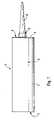
- FIG. 1is a side elevational view of a cartridge assembly according to the present invention
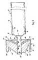
- FIG. 2is a longitudinal cross section through a cartridge assembly according to the present invention
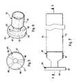
- FIG. 3is an enlarged cross section taken along the line 3 — 3 shown in FIG. 7 through a locating and transporting member and a flow directing member shown in FIGS. 2 and 7 ;
- FIG. 4is a rear elevational view of the locating and transporting member and the flow directing member shown in FIGS. 2 and 7 ;
- FIG. 5is a front elevational view of the locating and transporting member and the flow directing member shown in FIGS. 2 and 7 ;
- FIG. 6is a perspective view of the locating and transporting member and the flow directing member shown in FIGS. 2 and 7 ;
- FIG. 7is a side elevational view of the locating and transporting member and the flow directing member shown in FIGS. 2 and 7 ;
- FIG. 8is a side elevational view of a mixing unit according to the present invention and shown in FIG. 2 ;
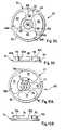
- FIG. 9Ais a plan view of an inner surface of a rear plate of the mixing unit.
- FIG. 9Bis a side elevational view of the rear plate shown in FIG. 9A ;
- FIG. 10Ais a plan view of an inner surface of a front plate of the mixing unit
- FIG. 10Bis a side elevational view of the front plate shown in FIG. 10A ;
- FIG. 11Ais a cross sectional view of a mixing body of the mixing unit taken along the lines 11 — 11 of FIGS. 12 and 13 ;
- FIGS. 11B–11Dillustrate a mixing path and the resulting flow of the components through the mixing body illustrated in FIG. 11A ;
- FIG. 12is a plan view of a rear end of the mixing body shown in FIGS. 11A–11D ;
- FIG. 13is a plan view of a front end of the mixing body shown in FIGS. 11A–11D ;
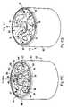
- FIG. 14is an elevational view of a piercing rod according to the present invention.
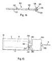
- FIG. 15illustrates an alternative embodiment of the present invention with a removably attached mixing unit
- FIG. 16Aillustrates a mixing element according to the present invention
- FIG. 16Billustrates an alternative embodiment of a passive mixing element that may be utilized in the various embodiments of mixing unit.
- the present inventionincludes a two component meter mix dispenser that includes a disposable cartridge assembly 1 for holding components A, B that can be mixed together to form a material, such as a resin.
- the cartridge assembly 1is sized and configured for use with a conventional caulking gun (not shown) or other known dispensing devices.
- the disposable cartridge assembly 1includes a conventional, elongated rigid tubular cylindrical mixer body 2 with a front end 3 , a rear end 5 and a component containing interior 9 .
- the front end 3includes an end plate 4 with a centrally located discharge opening 6 .
- the end plate 4also includes a fastening system 7 for securely receiving and retaining a discharge nozzle 8 .
- the fastening system 7can include threads for mating with corresponding threads on the discharge nozzle 8 .
- the fastening system 7could include a known friction or snap fit system for securing the discharge nozzle about the discharge opening 6 .
- the cylindrical body 2 , end plate 4 and discharge nozzle 8can be formed by any manner of conventional construction.
- the cylindrical body 2can be formed of metal, cardboard or plastic, while the end plate 4 and discharge nozzle 8 can be metal or plastic.
- the end plate 4is formed of a plastic, it can be integrally molded with the body 2 as a single, continuous unit.
- the end plate 4 and discharge nozzle 8can be integrally molded together as a single unit, no matter if the end plate 4 is molded together with the cylindrical body 2 .
- the end plate 4can be removably secured to the body 2 in a known manner, such as by cooperating threaded surfaces.
- the rear end 5 of the cartridge 1includes a conventional cup shaped plunger 10 that has an outer circumference that frictionally engages the inner walls of the body 2 .
- the plunger 10prevents the components A, B within the body 2 from escaping as is well known in the art.
- the plunger 10can be formed of any suitable material used in the art such as plastics or metal.
- the plunger 10is moved from the rear end 5 toward the front end 3 by the advancing action of a push rod of a caulking gun in order to expel the components A, B from the body 2 as is known.
- the body 2also includes a collapsible container 12 for holding a first of the two components A.
- An outer surface of the collapsible container 12 and an inner surface of the body 2define a reservoir 13 for holding a second of the two components B.
- the walls of the container 12 and the plunger 10keep the two components separated and isolated from each other.
- the container 12is formed by a cylindrical tube 15 made of a thin flexible film, such as a synthetic plastic film that is resistant to both components A, B of the mixture contained within the body 2 .
- the tube 15is closed at both ends for securely holding the contained component A.
- a front end of the tube 15is bonded by an adhesive or radiant energy (light, heat, etc.) to a locating and transporting member 16 that slides within the body 2 .
- the locating and transporting member 16has a collar 18 around which the front end of the tube 15 is secured. In an alternative embodiment, the collar 18 is secured around the outside of the front end of the tube 15 .
- the front end of the collar 18tapers toward and is secured to a rear potion of a flow directing member 40 which slides within the body 2 with collar 18 .
- Collar 18can be integrally formed with flow directing member 40 as a single unit or they can be formed as separate units and secured together to form a single unit.
- the front end of the collar 18has a centrally located opening 19 that communicates with a rear opening 41 of the flow directing member 40 to deliver component A from the tube 15 to a receiving well 42 in the flow directing member 40 as shown in FIG. 3 .
- the flow directing member 40also includes a plurality of channels 45 that extend from its rear, component contacting surface 43 to the receiving well 42 . While three channels 45 are illustrated in FIG.
- any number of channels 45can be used.
- the flow directing member 40could include one to six channels 45 .
- the rear openings of the channels 45are substantially elliptical or substantially circular in shape and open to the reservoir 13 so that the well 42 is in communication with the reservoir 13 for delivering the component B within the reservoir 13 to the well 42 .
- the larger the opening of channel 45the larger the amount of component B delivered to the well 42 at one time.
- the flow rate of component Bcan be tightly controlled.
- the flow rate of component Bcan be controlled to be the same as the flow rate of component A.
- the flow rate of one componentcan be a fraction of the flow rate of the other component so that more of one component is received.
- the diameter of these channels 45is an effective way to control the flow rate of the components A and B when they have very different viscosities. The actual diameter, number of channels 45 and flow rates will depend on the components being mixed. It is contemplated that the channels 45 could include rupturable seals.
- a front opening 44 in the flow directing member 40is open to the well 42 to deliver and direct the components A, B from the well 42 to a mixing unit 60 in response to the movement of the piston 10 .
- the flow directing member 40also includes a disc-shaped sidewall 47 that contacts the inner walls of body 2 to position the flow directing member 40 within the body 2 and to provide support to the well 42 to prevent longitudinal and radial collapse.
- a forward surface 48 of the flow directing member 40includes ridges 46 that provide support and additional size to the channels 45 as shown in FIGS. 3 and 5 . The greater the distance that the ridges 46 extend from the forward surface 48 , the larger the width/diameter of the channels 45 can be made.
- the flow directing member 40also includes a forward recess 49 .
- FIG. 3also illustrates a rupturable seal 26 that is positioned over the opening 19 for initially sealing the rear opening 41 from the interior of the tube 15 .
- the seal 26could be positioned within the well 42 over the opening 41 .
- a rupturable seal 27is also positioned over the opening 44 for sealing the well 42 including the components A, B from the mixing unit 60 .
- the rupturable seals 26 , 27are formed either by the film of the tube or by a separate membrane of, for example, aluminum foil. However, other known rupturable sealing materials can also be used.
- a light gauge compression coil spring 110( FIG. 2 ) can be positioned and sealed within the tube 15 .
- the coil spring 110has a free length that is at least equal to the distance between the plunger 10 and the discharge opening 6 at the other end of the cartridge 1 .
- the spring 110has a diameter substantially the same as that of the tube 15 , and acts both to support the walls of the tube 15 against radial collapse, and to hold the tube against the plunger 10 .
- the tube 15in place of the spring 110 , can be molded to contain ribs that allow the bag to collapse like an accordion when the plunger 10 , is pushed. Tube 15 can also be constructed in a manner where rigid walls collapse when plunger 10 is pushed.
- the mixing unit 60shown in FIGS. 2 and 8 – 13 , is also provided within the body 2 for mixing the components A, B delivered from the flow directing member 40 through opening 44 .
- the mixing unit 60includes a rear plate 61 , a front plate 71 and a mixing body 80 positioned between the plates 61 , 71 ( FIG. 8 ).
- the mixing unit 60is about 1.75 inches long (length being measured in a direction parallel to longitudinal axis of the cartridge assembly 1 ). The length of the mixing unit 60 is not dependent on the number of mixing elements 140 .
- the rear plate 61 , front plate 71 and mixing body 80define a substantially sinusoidal shaped mixing path that extends around the mixing unit 60 as discussed below.
- the rear plate 61includes a central, inlet opening 62 that is aligned with and in communication with the front opening 44 of the flow directing member 40 so that the unmixed components A, B are delivered from the well 42 to the mixing body 80 after being united in the flow directing member 40 .
- the rear plate 61also includes a rear surface 63 that forms the rear outer surface of the mixing unit 60 , and an inner surface 64 that faces the mixing body 80 .
- the inner surface 64includes a plurality of component flow guide channels 65 spaced around its circumference.
- Each channel 65has at least one sidewall 66 that extends from the inner surface 64 in the direction of the mixing body 80 .
- the sidewalls 66 of the channels 65cooperate with the mixing body 80 as discussed below for guiding the components A, B along the mixing path within the mixing unit 60 .
- a first channel 67extends radially across the rear plate 61 and has a discontinuous sidewall 66 with an end that is open to the inlet opening 62 for receiving the components A, B that enter the mixing unit 60 through the inlet opening 62 as shown in FIG. 9A .
- the remaining channels 69 A, 69 B and 69 Care substantially arcuate in shape and substantially coextensive with a portion of the circumference of the rear plate 61 .
- the channels 69 A– 69 Chave at least one continuous sidewall 66 that is shaped substantially like a kidney bean and spaced from an edge of the plate 61 a distance that is equal to about the thickness of the walls of the mixing body 80 .
- the shape and position of the channels 69 A– 69 Ccooperate with the mixing body 80 to form a portion of the mixing body.
- the channels 67 and 69 A–Ccould include any shape.
- FIG. 9Aalso illustrates grooves 68 are formed in the inner surface 64 for engaging lips on the mixing body 80 to seal the area within the plate 61 and around opening 62 .
- the front plate 71includes a central, outlet opening 72 .
- outlet opening 72has a forwardly extending extension 73 ( FIG. 8 ) that is received within the extended discharge opening 6 and in the direction of installed discharge nozzle 8 .
- the extension 73includes a plurality of internal ribs 74 that extend inwardly into the opening 72 , as shown, to support the piercing rod 120 ( FIG. 14 ). While four ribs 74 are shown, any number of ribs 74 may be included.
- the front plate 71also includes a plurality of component flow guide channels 75 on its inner face for guiding the components A, B along the mixing path within the mixing unit 60 as discussed above with respect to rear plate 61 and channels 65 .
- the channels 75are spaced around the circumference of plate 71 as illustrated in FIG. 10A .
- Each channel 75has at least one sidewall 76 that extends in the direction of the mixing body 80 .
- Channels 79 A, 79 B and 79 Care shaped substantially like a kidney bean and have a continuous sidewall 76 as discussed above with respect to channels 69 A–C.
- the channels 79 A– 79 Ccooperate with the mixing body 80 to deliver the components A, B to a fourth channel 77 , which then directs the mixed components A, B to the discharge nozzle 8 .
- the channel 77extends radially across the front plate 71 and has a discontinuous sidewall 76 with an end that is open to the outlet opening 72 for delivering the mixed components A, B to the outlet opening 72 and the discharge nozzle 8 .
- FIG. 10Aalso illustrates grooves 78 are formed in the inner surface for engaging lips on the mixing body 80 to seal the area within the plate 71 and around opening 72 .
- the mixing body 80is cylindrical in shape, has a circular cross section and has a plurality of circumferentially positioned mixing housings 84 – 87 .
- the mixing housings 84 – 87are circumferentially spaced from each other by open gaps/regions 180 as shown in FIG. 12 .
- Each housing 84 – 87includes at least one mixing cylinder 89 that has a circular cross section and that extends longitudinally along the length of the mixing body 80 .
- a flow channel 88surrounds the ends of the mixing cylinders 89 at the rear end 82 of the mixing cylinders 89 of each housing 84 – 87 , and thereby connects the mixing cylinders 89 of the same housing 84 – 87 for delivering the components A, B from one mixing cylinder 89 to the adjacent mixing cylinder 89 of the same housing 84 – 87 .
- the mixing cylinders 89 of adjacent housings 84 – 87are isolated at the rear end 82 by the sidewalls of their respective flow channels 88 and the gaps 180 .
- the mixing cylinders 89 of adjacent mixing housings 84 – 87are connected and in communication with each other by a flow channel 88 so that the components A, B can flow from a mixing cylinder 89 of one mixing housing 84 – 87 to a mixing cylinder of an adjacent mixing housing 84 – 87 .
- the mixing cylinders 89 of the same mixing housing 84 – 87are isolated from each other at the front end 83 of the mixing body 80 by the wall(s) of the channels 88 .
- the mixing housing 87extends radially away from the center of the mixing body 80 toward the sidewall of the mixing body 80 .
- One mixing cylinder 89 of the housing 87is the center cylinder 90 of the mixing body 80 .
- the cylinder 90is open and in communication with mixing cylinder 99 (shown in FIG. 13 ) and the central aperture 72 .
- the cylinder 90includes a plate 91 for directing the compounds entering through aperture 62 into the first mixing cylinder 93 to begin the mixing process ( FIG. 12 ).
- the plate 91is spaced along the length of the cylinder 90 from the rear end 82 and has a centrally positioned opening 92 with a diameter sized to receive a stem 121 of piercing rod 120 .
- the opening 92has a diameter that is only slightly larger (1 to 5 mm) than that of the stem 121 of the piercing rod 120 ( FIG. 14 ) so that a friction fit can be achieved between the stem 121 and the sidewall of the opening 92 along the length of the stem 121 except at the portions of reduced cross section 123 .
- These reduced portions 123also permit registration of the position of a piercing head 124 of the piercing rod 120 .
- the piercing head of the piercing rod 120can include a pointed tip 125 and a plurality of puncturing ribs 126 .
- the positioning of the plate 91 from the rear end 82 and the diameter of the cylinder 90 and the opening 62provide a recess 128 that is large enough to receive and contain piercing head 124 so that it will not prematurely puncture anything within the body 2 .
- the mixing body 80could include any number of mixing housings, for example between two and ten housings, and any number of mixing cylinders, such as between one and ten. As illustrated, three of the housings 84 – 86 have a substantially kidney bean shaped cross section and the radially extending housing 87 has a substantially keyhole shaped cross section. However, as with the channels 65 , 75 , the housings 84 – 87 could have any shape. Additionally, each mixing cylinder 89 is an open ended tube with a round cross section. However, any shaped cross section could be used.
- passive mixing elements 140are positioned within the mixing cylinders 89 . While it is contemplated that all of the mixing cylinders 89 include these mixing elements 140 , it is also possible that fewer than all, possibly only one, of the mixing cylinders 89 include the mixing elements 140 . For example, mixing cylinder 93 may not include a mixing element 140 .
- the mixing elements 140may be formed in various arrays and of any rigid or substantially rigid material. In preferred embodiments, the elongated mixing elements 140 ( FIG. 16A ) are formed of plastic or metal having sufficient rigidity to resist displacement and deflection by the material passing through the mixing cylinder.
- the mixing elements 140include those sold under the trademark “STATIC MIXER” by Kenics Corporation, and described in U.S. Pat. No. 3,286,992, which is hereby incorporated by reference.
- the mixing elements 140may include mixing blades 141 molded into the walls of the mixing cylinders 89 .
- the actual structure and shape of the blades 141 and the mixing elements 140will depend upon the viscosity of the components being mixed, since it is necessary to reduce obstructions in the mixing cylinders to a degree that will permit the mixed compounds to be dispensed at a desired rate without the development of excessive back pressure in the cartridge 1 .
- the cartridge 1is loaded into a conventional caulking gun, and the piercing rod 120 is advanced toward the rear end 5 of the body 2 .
- the head 124 of the piercing rod 120moves from its rest position, where the head 124 is retracted into the mixing cylinder 90 , through the seals 26 , 27 and into the interior of the cylinder 15 .
- the piercing rod 120is pushed into the tube so that the flat section 123 , is parallel to the top of the nozzle 6 , this will ensure that barriers 26 and 27 are punctured and no longer prevent components A and B from contacting each other.
- the nozzle 8is screwed into the discharge opening 6 .
- the first component A from the inner, collapsible container 12is advanced into the well 42 past the ruptured seal 26 , whilst the second component B in the reservoir 13 is forced through the channels 45 and into the well 42 where it meets with the first component A.
- the components A, Bthen pass through the openings 44 , 62 and into the centrally located mixing cylinder 90 .
- FIGS. 11B–11DUpon entering the mixing cylinder 90 , the components A, B contact the plate 91 and are directed across a portion of the rear end 82 by the plate 91 , the sidewalls of the channel 88 and the channel 65 to the first, circumferentially positioned mixing cylinder 93 of the radially extending mixing housing 87 .
- the components A, Bpass through the mixing elements 140 along the length of the mixing cylinder 93 as they are forced toward the front end 83 of the mixing body 80 .
- the mixing cylinder 93opens to a channel 88 and the cover channel 75 .
- each channel 88extends around one of the mixing cylinders 89 of two adjacent mixing housings 84 – 87 .
- the mixed components A, Bare forced out of the mixing cylinder 93 , they travel into and across the channel 88 extending along the front end 83 and into a mixing cylinder 94 of the adjacent mixing housing 84 .
- the mixed components A, Bare then forced through the mixing cylinder 94 where they pass the mixing elements 140 as the mixed components continue along the mixing path and return to the rear end 82 of the mixing body 80 .
- the mixed components A, Bare forced along the channel 88 at the rear end 82 and into mixing cylinder 95 of the same mixing housing 84 .
- the mixing cylinder 95is circumferentially spaced from mixing cylinder 94 while still forming part of the mixing housing 84 .
- the mixed components A, Bare again forced toward the front end 83 of the mixing body 80 . If mixing elements 140 are positioned within the mixing cylinder 95 , the components are further mixed as they pass through the mixing cylinder 95 . Upon reaching the front end 83 , the mixed components A, B travel within another channel 88 and into the mixing channel 96 of the next mixing housing 85 . The mixed components A, B are then forced through the mixing channel 96 toward the rear end 82 and past any contained mixing elements 140 . Similar to that previously described, the mixed components A, B then travel across a portion of the rear end 82 within another channel 88 of the mixing housing 80 in the direction of the next circumferentially positioned mixing channel 97 of mixing housing 85 . Upon reaching the mixing channel 97 , the mixed components A, B enter the mixing channel 97 and are forced past any contained mixing elements 140 in the direction of the front 83 of the mixing housing 80 .
- the method of forcing the mixed components A, B along the mixing path through the mixing cylinders 90 and 93 – 99 and along the channels 88continues until the mixed components A, B are forced through the mixing cylinder 99 and past any mixing elements 140 contained there within.
- the mixed componentsAfter exiting the mixing cylinder 99 at the front end 83 of the mixing body 80 , the mixed components enter the channel 88 A bounded by the mixing body and the end plate 71 .
- the forced components A, Btravel through the channel 88 A to an opening 105 that opens into the front of the central mixing channel 90 and out the discharge opening 6 and into the discharge nozzle 8 for application.
- the front end 83 of the mixing cylinder 99is at the terminal end of the mixing path, whereas the rear end 82 of mixing element 93 is at the beginning end of the mixing path. Also can be seen from the figures, the front end 83 of the mixing element 93 is counter clockwise to the rear end 82 of the mixing element 93 when the mixing path extends in a clockwise pattern. The converse is also true if the mixing path extends in a counter-clockwise pattern.
- the mixing cylinders 89are spaced from each other around the circumference of the mixing body by a predetermined distance, such as 360° or the length of the circumference divided by N, where N is the number of circumferentially spaced mixing cylinders 93 – 99 , not including the centrally spaced mixing cylinder 90 .
- a predetermined distancesuch as 360° or the length of the circumference divided by N, where N is the number of circumferentially spaced mixing cylinders 93 – 99 , not including the centrally spaced mixing cylinder 90 .
- Other known ways of spacing the cylinderscan also be used.
- FIG. 15shows an alternative embodiment that permits the contents of the cartridge 1 to be used over an extended period.
- the mixing unit 260is a separate external unit that is removably secured to the body 2 .
- the mixing unit 260can have a coupling 250 that threadably or frictionally fits it onto a well 242 that is removably secured on the end of the body 2 .
- the mixing unit 260also has a coupling 255 for the nozzle 8 .
- the well 242is connected to the mixing unit 260 and includes a neck 280 that has concentric passageways 281 , 282 that deliver the components to the well 242 .
- the seal 26( FIG. 3 ) covers the openings of the passageways 281 , 282 .
- a removable screw cap(not shown) can be used to cover seal 26 before the mixing unit 260 is secured to the coupling 250 .
- the concentric passageways 281 , 282 for the two componentsprovide for the saving of any unused portions of the contents of the cartridge by removing the well 242 and the mixing unit 260 and replacing the cap over the punctured seal 26 .
- a cleaned or new well 242 and mixing unit 260are attached to the coupling 250 before the cartridge 1 is used again.
- cartridgesor “sausages” in which the conventional rigid body is replaced by a flexible tubular bag containing the material to be dispensed, the remaining functions of the body being provided by the gun itself.
- the present inventioncan be adapted for such a use as described in U.S. Pat. No. 4,676,657.
- a flexible cylindrical tubeof similar construction to cylinder 15 , previously described, replaces the body 2 .
- the remainder of the cartridgeis substantially the same as described above with respect to the cartridge in FIG. 1 .
- FIG. 16Billustrates an alternative form of the passive mixing element 340 .
- Each element 340is formed by a disc of metal or synthetic plastic, which has been slit from diametrically opposed points on its periphery to spaced points close to its center, so that opposite halves 342 , 343 of the disc may be twisted relative to one another to produce mixing elements as shown in the Figure. Similar elements may be molded integrally with a mixing element 340 rather than being formed separately.
Landscapes
- Chemical & Material Sciences (AREA)
- Dispersion Chemistry (AREA)
- Chemical Kinetics & Catalysis (AREA)
- Engineering & Computer Science (AREA)
- Mechanical Engineering (AREA)
- Coating Apparatus (AREA)
- Containers And Packaging Bodies Having A Special Means To Remove Contents (AREA)
- Details Of Rigid Or Semi-Rigid Containers (AREA)
- Preparation Of Compounds By Using Micro-Organisms (AREA)
Abstract
Description
Claims (20)
Priority Applications (1)
| Application Number | Priority Date | Filing Date | Title |
|---|---|---|---|
| US10/778,349US6971787B2 (en) | 2002-03-12 | 2004-02-17 | Apparatus and method for mixing and dispensing components of a composition |
Applications Claiming Priority (2)
| Application Number | Priority Date | Filing Date | Title |
|---|---|---|---|
| US10/094,963US6705756B2 (en) | 2002-03-12 | 2002-03-12 | Apparatus and method for mixing and dispensing components of a composition |
| US10/778,349US6971787B2 (en) | 2002-03-12 | 2004-02-17 | Apparatus and method for mixing and dispensing components of a composition |
Related Parent Applications (1)
| Application Number | Title | Priority Date | Filing Date |
|---|---|---|---|
| US10/094,963ContinuationUS6705756B2 (en) | 2002-03-12 | 2002-03-12 | Apparatus and method for mixing and dispensing components of a composition |
Publications (2)
| Publication Number | Publication Date |
|---|---|
| US20040159678A1 US20040159678A1 (en) | 2004-08-19 |
| US6971787B2true US6971787B2 (en) | 2005-12-06 |
Family
ID=27804264
Family Applications (2)
| Application Number | Title | Priority Date | Filing Date |
|---|---|---|---|
| US10/094,963Expired - LifetimeUS6705756B2 (en) | 2002-03-12 | 2002-03-12 | Apparatus and method for mixing and dispensing components of a composition |
| US10/778,349Expired - LifetimeUS6971787B2 (en) | 2002-03-12 | 2004-02-17 | Apparatus and method for mixing and dispensing components of a composition |
Family Applications Before (1)
| Application Number | Title | Priority Date | Filing Date |
|---|---|---|---|
| US10/094,963Expired - LifetimeUS6705756B2 (en) | 2002-03-12 | 2002-03-12 | Apparatus and method for mixing and dispensing components of a composition |
Country Status (9)
| Country | Link |
|---|---|
| US (2) | US6705756B2 (en) |
| EP (1) | EP1381475B1 (en) |
| JP (1) | JP2005519736A (en) |
| AT (1) | ATE429979T1 (en) |
| AU (1) | AU2003208236A1 (en) |
| CA (1) | CA2447449C (en) |
| DE (1) | DE60327390D1 (en) |
| ES (1) | ES2326634T3 (en) |
| WO (1) | WO2003076081A1 (en) |
Cited By (18)
| Publication number | Priority date | Publication date | Assignee | Title |
|---|---|---|---|---|
| US20070253287A1 (en)* | 2006-04-05 | 2007-11-01 | Lennart Myhrberg | Disposable unit |
| USD607345S1 (en) | 2009-01-02 | 2010-01-05 | Bruce Bleimeyer | Caulk cartridge |
| US8308681B2 (en) | 2005-02-09 | 2012-11-13 | Children's Medical Center Corporation | Device for mixing and delivering fluids for tissue repair |
| US8642735B2 (en) | 1999-06-22 | 2014-02-04 | Children's Medical Center Corporation | Biologic replacement for fibrin clot |
| US9308242B2 (en) | 2006-09-28 | 2016-04-12 | Children's Medical Center Corporation | Methods and products for tissue repair |
| US9757495B2 (en) | 2013-02-01 | 2017-09-12 | Children's Medical Center Corporation | Collagen scaffolds |
| US20180111138A1 (en)* | 2016-10-25 | 2018-04-26 | Advanced Solutions Life Sciences, Llc | Static Mixing Device and Method of Manufacturing Static Mixing Device |
| US10773433B2 (en) | 2016-07-01 | 2020-09-15 | Sulzer Mixpac Ag | Cartridge, core, mold and method of manufacturing a cartridge |
| US10786232B2 (en) | 2006-01-25 | 2020-09-29 | The Children's Medical Center Corporation | Methods and procedures for ligament repair |
| US10870127B2 (en) | 2018-10-02 | 2020-12-22 | Sulzer Mixpac Ag | Cartridge for a mixing and dispensing system |
| US10906702B2 (en) | 2018-10-02 | 2021-02-02 | Sulzer Mixpac Ag | Cartridge, method of manufacturing a cartridge, dispensing assembly and method of assembling a dispensing assembly |
| USD913111S1 (en)* | 2018-02-26 | 2021-03-16 | Abacocay, Llc | Dispenser cartridge |
| US11053064B2 (en) | 2016-07-01 | 2021-07-06 | Sulzer Mixpac Ag | Cartridge, core, mold and method of manufacturing a cartridge |
| US11117145B2 (en)* | 2018-02-02 | 2021-09-14 | Ag Growth International Inc. | Atomizer mixing chamber for a seed treater |
| US11484578B2 (en) | 2012-02-01 | 2022-11-01 | Children's Medical Center Corporation | Biomaterial for articular cartilage maintenance and treatment of arthritis |
| US11772851B2 (en) | 2021-06-21 | 2023-10-03 | Medmix Switzerland Ag | Liquid applicator |
| US11814232B2 (en) | 2018-10-02 | 2023-11-14 | Medmix Switzerland Ag | Cartridge, method of manufacturing a cartridge, dispensing assembly and method of assembling a dispensing assembly |
| US12377193B2 (en) | 2016-07-06 | 2025-08-05 | The Children's Medical Center Corporation | Indirect method of articular tissue repair |
Families Citing this family (17)
| Publication number | Priority date | Publication date | Assignee | Title |
|---|---|---|---|---|
| US7011650B2 (en)* | 1999-09-09 | 2006-03-14 | Paradigm Medical, Llc | Multiple-dose syringe with collapsible container |
| DE10341256A1 (en)* | 2003-09-04 | 2004-07-01 | Klebchemie, M.G. Becker Gmbh & Co Kg | Adhesive fluid dispensing device has heating insert for adhesive fluid cartridge for heating adhesive fluid to temperature sufficient for plunger operation for adhesive fluid delivery point throughflow |
| EP1602415A1 (en)* | 2004-06-04 | 2005-12-07 | 3M Espe AG | Syringe for a multi-component paste |
| DE202005001203U1 (en)* | 2005-01-26 | 2006-06-14 | Sulzer Chemtech Ag | Multicomponent foil container |
| USD567327S1 (en)* | 2006-07-27 | 2008-04-22 | Rigo S.R.L. | Nozzle |
| USD567899S1 (en)* | 2006-07-27 | 2008-04-29 | Rigo S.R.L. | Nozzle |
| CN101883604A (en)* | 2006-11-28 | 2010-11-10 | 康隆有限公司 | Tissue prosthesis insertion system and method |
| EP2285312A4 (en)* | 2008-05-01 | 2014-03-12 | Columna Pty Ltd | Systems methods and apparatuses for formation and insertion of tissue prostheses |
| US8210453B2 (en) | 2008-09-12 | 2012-07-03 | Confluent Surgical, Inc. | Spray applicator |
| US8523805B2 (en)* | 2008-10-29 | 2013-09-03 | Biomet Biologics, Llc | Method and apparatus for containing, transporting, and providing a material |
| CN102464149B (en)* | 2010-11-02 | 2016-02-10 | 广东省有机硅工程技术研究开发中心 | The unmixed double components of adhesive list packaging improved |
| RU2455055C1 (en)* | 2010-12-23 | 2012-07-10 | Общество с ограниченной ответственностью "Полимеры" | Device for fast mixing of reagents |
| CN103998150B (en)* | 2011-10-17 | 2017-07-21 | 苏舍米克斯帕克有限公司 | multi-component cartridge |
| RU2486949C1 (en)* | 2012-04-06 | 2013-07-10 | Федеральное государственное бюджетное образовательное учреждение высшего профессионального образования "Пензенская государственная сельскохозяйственная академия" | Mixing filter of mineral fuel and vegetable oil |
| US9067711B2 (en)* | 2012-11-06 | 2015-06-30 | Sonoco Development, Inc. | Storage and dispensing device |
| AU2018334107B2 (en)* | 2017-09-18 | 2021-02-11 | Cmp Products Limited | Apparatus for dispensing curable material into a cable gland |
| EP3505231A1 (en)* | 2017-12-29 | 2019-07-03 | Sulzer Mixpac AG | Mixer, multi-component dispenser, and method of dispensing multi-component material from a multi-component dispenser |
Citations (37)
| Publication number | Priority date | Publication date | Assignee | Title |
|---|---|---|---|---|
| US1535529A (en)* | 1921-06-11 | 1925-04-28 | Hopkins Nevil Monroe | Collapsible tube |
| US1639699A (en)* | 1923-08-29 | 1927-08-23 | Gilmont Products Corp | Article of manufacture comprising container and contents therefor |
| US1698404A (en)* | 1923-10-16 | 1929-01-08 | Gilmont Products Corp | Ultiple-compartment collapsible tube |
| US2085132A (en) | 1934-11-26 | 1937-06-29 | Bethlehem Steel Corp | Mixer |
| US3159312A (en) | 1962-09-28 | 1964-12-01 | Budd Co | Dispensing device for mixing two viscous fluids |
| US3185447A (en) | 1963-03-25 | 1965-05-25 | Hach Chemical Co | Analyzer mixing apparatus |
| US3286992A (en) | 1965-11-29 | 1966-11-22 | Little Inc A | Mixing device |
| US3323682A (en) | 1965-10-06 | 1967-06-06 | Chem Dev Corp | Disposable cartridge for gun-type dispensers |
| US3623704A (en) | 1970-08-03 | 1971-11-30 | Dow Corning | Static mixing device |
| US3701619A (en) | 1969-11-14 | 1972-10-31 | American Enka Corp | Mixing apparatus |
| US3799509A (en) | 1972-03-02 | 1974-03-26 | Du Pont | Mixer for a melt spinning apparatus |
| US4340154A (en)* | 1980-10-24 | 1982-07-20 | Voplex Corporation | Caulker for dispensing two viscous components |
| US4366919A (en)* | 1978-05-01 | 1983-01-04 | Coaxial Cartridges, Inc. | Composite cartridge and device for metering extrusion of contents |
| US4585149A (en)* | 1982-10-27 | 1986-04-29 | Wella Aktiengesellschaft | Double container for two separated fluids |
| US4643336A (en) | 1984-12-05 | 1987-02-17 | Kent-Moore Corporation | Mixing and dispensing gun |
| US4676657A (en) | 1985-09-30 | 1987-06-30 | Alexander Botrie | Cartridge for the dispensing of two component systems from caulking guns |
| US4690306A (en)* | 1985-08-12 | 1987-09-01 | Ciba-Geigy Corporation | Dispensing device for storing and applying at least one liquid or pasty substance |
| US4846373A (en)* | 1982-09-07 | 1989-07-11 | Penn Laurence R | Apparatus for proportioning or for proportioning and mixing plural different fluid compositions |
| US4969767A (en)* | 1988-09-26 | 1990-11-13 | Colgate-Palmolive Company | Multicolor surface striping device |
| US4969747A (en) | 1990-01-26 | 1990-11-13 | Laurence Colin | Reverse flow dispensing mixer |
| US5295613A (en)* | 1991-07-10 | 1994-03-22 | Societe De Prospection Et D'inventions Techniques (S.P.I.T.) | Tubular cartridge for storing and applying a non-solid product, and a drive and thrust assembly for the cartridge |
| US5310091A (en)* | 1993-05-12 | 1994-05-10 | Tremco, Inc. | Dual product dispenser |
| US5328056A (en)* | 1992-03-16 | 1994-07-12 | Cebal S.A. | Tube and distributor incorporating the latter for storing and distributing two creamy or pasty products |
| US5350233A (en) | 1992-09-22 | 1994-09-27 | Reagent Chemical & Research, Inc. | Mixing apparatus and method for forming a blended composite material from a plurality of components |
| US5386928A (en) | 1993-11-15 | 1995-02-07 | Minnesota Mining And Manufacturing Company | Dual collapsible tube dispensing assembly |
| US5433084A (en) | 1993-12-01 | 1995-07-18 | Food Systems Partnership, Ltd. | Aerator for viscous materials |
| US5542578A (en) | 1990-08-23 | 1996-08-06 | Viking Industries, Inc. | Dispensing gun for ratio sensitive two-part material |
| US5566860A (en)* | 1994-09-08 | 1996-10-22 | Liquid Control Corporation | Dual component cartridge |
| US5647510A (en)* | 1993-08-20 | 1997-07-15 | Keller; Wilhelm A. | Multiple component metering and relative proportioning device with collapsible cartridge |
| US5893486A (en)* | 1997-05-27 | 1999-04-13 | Liquid Control Corporation | Foam dispensing device |
| US5909959A (en) | 1997-11-04 | 1999-06-08 | Gerich; Horst | Compact fluid mixer |
| US6079868A (en) | 1997-12-18 | 2000-06-27 | Advanced Bio Surfaces, Inc. | Static mixer |
| US6129243A (en)* | 1995-10-16 | 2000-10-10 | Chesebrough-Pond's Usa Co., Division Of Conopco, Inc. | Dual tube dispenser and adaptor |
| US6176395B1 (en)* | 1999-04-21 | 2001-01-23 | Pechiney Plastic Packaging, Inc. | Dual dispense container |
| US6257450B1 (en)* | 1999-04-21 | 2001-07-10 | Pechiney Plastic Packaging, Inc. | Dual dispense container having cloverleaf orifice |
| US6609634B2 (en)* | 2000-09-08 | 2003-08-26 | L'oreal S.A. | Dispensing device and methods |
| US6634524B1 (en)* | 1999-09-14 | 2003-10-21 | Fischbach Kg Kunststoff-Technik | Two-component cartridge for free-flowing media |
Family Cites Families (2)
| Publication number | Priority date | Publication date | Assignee | Title |
|---|---|---|---|---|
| DE3400280C1 (en) | 1984-01-05 | 1985-03-14 | Reinhardt-Technik Gmbh & Co, 5883 Kierspe | Dosing and mixing device for highly viscous two-component materials |
| DE3632242A1 (en) | 1986-09-23 | 1988-04-07 | Sinsch Joachim | Apparatus for metering and mixing viscous two-component materials |
- 2002
- 2002-03-12USUS10/094,963patent/US6705756B2/ennot_activeExpired - Lifetime
- 2003
- 2003-03-11ESES03706189Tpatent/ES2326634T3/ennot_activeExpired - Lifetime
- 2003-03-11WOPCT/CA2003/000332patent/WO2003076081A1/enactiveApplication Filing
- 2003-03-11AUAU2003208236Apatent/AU2003208236A1/ennot_activeAbandoned
- 2003-03-11ATAT03706189Tpatent/ATE429979T1/enactive
- 2003-03-11JPJP2003574340Apatent/JP2005519736A/enactivePending
- 2003-03-11CACA2447449Apatent/CA2447449C/ennot_activeExpired - Lifetime
- 2003-03-11DEDE60327390Tpatent/DE60327390D1/ennot_activeExpired - Lifetime
- 2003-03-11EPEP03706189Apatent/EP1381475B1/ennot_activeExpired - Lifetime
- 2004
- 2004-02-17USUS10/778,349patent/US6971787B2/ennot_activeExpired - Lifetime
Patent Citations (37)
| Publication number | Priority date | Publication date | Assignee | Title |
|---|---|---|---|---|
| US1535529A (en)* | 1921-06-11 | 1925-04-28 | Hopkins Nevil Monroe | Collapsible tube |
| US1639699A (en)* | 1923-08-29 | 1927-08-23 | Gilmont Products Corp | Article of manufacture comprising container and contents therefor |
| US1698404A (en)* | 1923-10-16 | 1929-01-08 | Gilmont Products Corp | Ultiple-compartment collapsible tube |
| US2085132A (en) | 1934-11-26 | 1937-06-29 | Bethlehem Steel Corp | Mixer |
| US3159312A (en) | 1962-09-28 | 1964-12-01 | Budd Co | Dispensing device for mixing two viscous fluids |
| US3185447A (en) | 1963-03-25 | 1965-05-25 | Hach Chemical Co | Analyzer mixing apparatus |
| US3323682A (en) | 1965-10-06 | 1967-06-06 | Chem Dev Corp | Disposable cartridge for gun-type dispensers |
| US3286992A (en) | 1965-11-29 | 1966-11-22 | Little Inc A | Mixing device |
| US3701619A (en) | 1969-11-14 | 1972-10-31 | American Enka Corp | Mixing apparatus |
| US3623704A (en) | 1970-08-03 | 1971-11-30 | Dow Corning | Static mixing device |
| US3799509A (en) | 1972-03-02 | 1974-03-26 | Du Pont | Mixer for a melt spinning apparatus |
| US4366919A (en)* | 1978-05-01 | 1983-01-04 | Coaxial Cartridges, Inc. | Composite cartridge and device for metering extrusion of contents |
| US4340154A (en)* | 1980-10-24 | 1982-07-20 | Voplex Corporation | Caulker for dispensing two viscous components |
| US4846373A (en)* | 1982-09-07 | 1989-07-11 | Penn Laurence R | Apparatus for proportioning or for proportioning and mixing plural different fluid compositions |
| US4585149A (en)* | 1982-10-27 | 1986-04-29 | Wella Aktiengesellschaft | Double container for two separated fluids |
| US4643336A (en) | 1984-12-05 | 1987-02-17 | Kent-Moore Corporation | Mixing and dispensing gun |
| US4690306A (en)* | 1985-08-12 | 1987-09-01 | Ciba-Geigy Corporation | Dispensing device for storing and applying at least one liquid or pasty substance |
| US4676657A (en) | 1985-09-30 | 1987-06-30 | Alexander Botrie | Cartridge for the dispensing of two component systems from caulking guns |
| US4969767A (en)* | 1988-09-26 | 1990-11-13 | Colgate-Palmolive Company | Multicolor surface striping device |
| US4969747A (en) | 1990-01-26 | 1990-11-13 | Laurence Colin | Reverse flow dispensing mixer |
| US5542578A (en) | 1990-08-23 | 1996-08-06 | Viking Industries, Inc. | Dispensing gun for ratio sensitive two-part material |
| US5295613A (en)* | 1991-07-10 | 1994-03-22 | Societe De Prospection Et D'inventions Techniques (S.P.I.T.) | Tubular cartridge for storing and applying a non-solid product, and a drive and thrust assembly for the cartridge |
| US5328056A (en)* | 1992-03-16 | 1994-07-12 | Cebal S.A. | Tube and distributor incorporating the latter for storing and distributing two creamy or pasty products |
| US5350233A (en) | 1992-09-22 | 1994-09-27 | Reagent Chemical & Research, Inc. | Mixing apparatus and method for forming a blended composite material from a plurality of components |
| US5310091A (en)* | 1993-05-12 | 1994-05-10 | Tremco, Inc. | Dual product dispenser |
| US5647510A (en)* | 1993-08-20 | 1997-07-15 | Keller; Wilhelm A. | Multiple component metering and relative proportioning device with collapsible cartridge |
| US5386928A (en) | 1993-11-15 | 1995-02-07 | Minnesota Mining And Manufacturing Company | Dual collapsible tube dispensing assembly |
| US5433084A (en) | 1993-12-01 | 1995-07-18 | Food Systems Partnership, Ltd. | Aerator for viscous materials |
| US5566860A (en)* | 1994-09-08 | 1996-10-22 | Liquid Control Corporation | Dual component cartridge |
| US6129243A (en)* | 1995-10-16 | 2000-10-10 | Chesebrough-Pond's Usa Co., Division Of Conopco, Inc. | Dual tube dispenser and adaptor |
| US5893486A (en)* | 1997-05-27 | 1999-04-13 | Liquid Control Corporation | Foam dispensing device |
| US5909959A (en) | 1997-11-04 | 1999-06-08 | Gerich; Horst | Compact fluid mixer |
| US6079868A (en) | 1997-12-18 | 2000-06-27 | Advanced Bio Surfaces, Inc. | Static mixer |
| US6176395B1 (en)* | 1999-04-21 | 2001-01-23 | Pechiney Plastic Packaging, Inc. | Dual dispense container |
| US6257450B1 (en)* | 1999-04-21 | 2001-07-10 | Pechiney Plastic Packaging, Inc. | Dual dispense container having cloverleaf orifice |
| US6634524B1 (en)* | 1999-09-14 | 2003-10-21 | Fischbach Kg Kunststoff-Technik | Two-component cartridge for free-flowing media |
| US6609634B2 (en)* | 2000-09-08 | 2003-08-26 | L'oreal S.A. | Dispensing device and methods |
Cited By (27)
| Publication number | Priority date | Publication date | Assignee | Title |
|---|---|---|---|---|
| US8642735B2 (en) | 1999-06-22 | 2014-02-04 | Children's Medical Center Corporation | Biologic replacement for fibrin clot |
| US8308681B2 (en) | 2005-02-09 | 2012-11-13 | Children's Medical Center Corporation | Device for mixing and delivering fluids for tissue repair |
| US10786232B2 (en) | 2006-01-25 | 2020-09-29 | The Children's Medical Center Corporation | Methods and procedures for ligament repair |
| US11076845B2 (en) | 2006-01-25 | 2021-08-03 | The Children's Medical Center Corporation | Methods and procedures for ligament repair |
| US11076846B2 (en) | 2006-01-25 | 2021-08-03 | The Children's Medical Center Corporation | Methods and procedures for ligament repair |
| US10786239B2 (en) | 2006-01-25 | 2020-09-29 | The Children's Medical Center Corporation | Methods and procedures for ligament repair |
| US10786238B2 (en) | 2006-01-25 | 2020-09-29 | The Children's Medical Center Corporation | Methods and procedures for ligament repair |
| US20070253287A1 (en)* | 2006-04-05 | 2007-11-01 | Lennart Myhrberg | Disposable unit |
| US9849213B2 (en) | 2006-09-28 | 2017-12-26 | Children's Medical Center Corporation | Methods and products for tissue repair |
| US9308242B2 (en) | 2006-09-28 | 2016-04-12 | Children's Medical Center Corporation | Methods and products for tissue repair |
| USD607345S1 (en) | 2009-01-02 | 2010-01-05 | Bruce Bleimeyer | Caulk cartridge |
| US11484578B2 (en) | 2012-02-01 | 2022-11-01 | Children's Medical Center Corporation | Biomaterial for articular cartilage maintenance and treatment of arthritis |
| US11839696B2 (en) | 2013-02-01 | 2023-12-12 | The Children's Medical Center Corporation | Collagen scaffolds |
| US9757495B2 (en) | 2013-02-01 | 2017-09-12 | Children's Medical Center Corporation | Collagen scaffolds |
| US10842914B2 (en) | 2013-02-01 | 2020-11-24 | The Children's Medical Center Corporation | Collagen scaffolds |
| US11826489B2 (en) | 2013-02-01 | 2023-11-28 | The Children's Medical Center Corporation | Collagen scaffolds |
| US11053064B2 (en) | 2016-07-01 | 2021-07-06 | Sulzer Mixpac Ag | Cartridge, core, mold and method of manufacturing a cartridge |
| US10773433B2 (en) | 2016-07-01 | 2020-09-15 | Sulzer Mixpac Ag | Cartridge, core, mold and method of manufacturing a cartridge |
| US12377193B2 (en) | 2016-07-06 | 2025-08-05 | The Children's Medical Center Corporation | Indirect method of articular tissue repair |
| US10864537B2 (en)* | 2016-10-25 | 2020-12-15 | Advanced Solutions Life Sciences, Llc | Static mixing device and method of manufacturing static mixing device |
| US20180111138A1 (en)* | 2016-10-25 | 2018-04-26 | Advanced Solutions Life Sciences, Llc | Static Mixing Device and Method of Manufacturing Static Mixing Device |
| US11117145B2 (en)* | 2018-02-02 | 2021-09-14 | Ag Growth International Inc. | Atomizer mixing chamber for a seed treater |
| USD913111S1 (en)* | 2018-02-26 | 2021-03-16 | Abacocay, Llc | Dispenser cartridge |
| US10906702B2 (en) | 2018-10-02 | 2021-02-02 | Sulzer Mixpac Ag | Cartridge, method of manufacturing a cartridge, dispensing assembly and method of assembling a dispensing assembly |
| US10870127B2 (en) | 2018-10-02 | 2020-12-22 | Sulzer Mixpac Ag | Cartridge for a mixing and dispensing system |
| US11814232B2 (en) | 2018-10-02 | 2023-11-14 | Medmix Switzerland Ag | Cartridge, method of manufacturing a cartridge, dispensing assembly and method of assembling a dispensing assembly |
| US11772851B2 (en) | 2021-06-21 | 2023-10-03 | Medmix Switzerland Ag | Liquid applicator |
Also Published As
| Publication number | Publication date |
|---|---|
| WO2003076081A1 (en) | 2003-09-18 |
| ATE429979T1 (en) | 2009-05-15 |
| AU2003208236A1 (en) | 2003-09-22 |
| US6705756B2 (en) | 2004-03-16 |
| ES2326634T3 (en) | 2009-10-16 |
| US20030174577A1 (en) | 2003-09-18 |
| EP1381475B1 (en) | 2009-04-29 |
| EP1381475A1 (en) | 2004-01-21 |
| US20040159678A1 (en) | 2004-08-19 |
| CA2447449C (en) | 2010-07-20 |
| CA2447449A1 (en) | 2003-09-18 |
| JP2005519736A (en) | 2005-07-07 |
| DE60327390D1 (en) | 2009-06-10 |
Similar Documents
| Publication | Publication Date | Title |
|---|---|---|
| US6971787B2 (en) | Apparatus and method for mixing and dispensing components of a composition | |
| US4261481A (en) | Fluid packaging kit for pressurized dispensing | |
| US3390814A (en) | Mixing device | |
| US4676657A (en) | Cartridge for the dispensing of two component systems from caulking guns | |
| US3828980A (en) | Dispenser for precisely metered dispensing of viscous fluids | |
| US4767026A (en) | Dispensing and mixing apparatus | |
| US4690306A (en) | Dispensing device for storing and applying at least one liquid or pasty substance | |
| US5419460A (en) | Container for flowable substances | |
| EP0624403B1 (en) | Dual product dispenser | |
| EP1205196B1 (en) | A prefilled telescoping multiple chamber ampoule device | |
| US5033650A (en) | Multiple barrel dispensing device | |
| US8544683B2 (en) | Multiple component dispensing cartridge and method with side-by-side fluid chambers | |
| US8177099B2 (en) | Cartridge | |
| US5065906A (en) | Double-chambered cartridge having semi-cylindrical pistons for use in a press-out gun | |
| WO1995005984A2 (en) | Multiple component metering and relative proportioning device with collapsible cartridge | |
| US20090052971A1 (en) | Delivery system | |
| US20130126558A1 (en) | Cove base nozzle for dispensing applications | |
| US5405056A (en) | Stereo dispensing container and system | |
| JP2008529899A (en) | 2-fluid cartridge with low waste fluid volume | |
| US20090308891A1 (en) | Cartridge | |
| US12325042B2 (en) | Common head having an offset partition for use with multi-component dispensing tools and a tubular liner arranged for locating within the common head | |
| US4949873A (en) | Semi-circular plungers for a plural component dispenser | |
| US11541406B2 (en) | Spray nozzle | |
| KR20200026091A (en) | Adapter mixer attachment | |
| JPS6211533A (en) | Resin mixing apparatus |
Legal Events
| Date | Code | Title | Description |
|---|---|---|---|
| STCF | Information on status: patent grant | Free format text:PATENTED CASE | |
| FEPP | Fee payment procedure | Free format text:PAT HOLDER CLAIMS SMALL ENTITY STATUS, ENTITY STATUS SET TO SMALL (ORIGINAL EVENT CODE: LTOS); ENTITY STATUS OF PATENT OWNER: SMALL ENTITY | |
| REFU | Refund | Free format text:REFUND - PAYMENT OF MAINTENANCE FEE, 4TH YEAR, LARGE ENTITY (ORIGINAL EVENT CODE: R1551); ENTITY STATUS OF PATENT OWNER: SMALL ENTITY | |
| FPAY | Fee payment | Year of fee payment:4 | |
| FPAY | Fee payment | Year of fee payment:8 | |
| AS | Assignment | Owner name:CHEMQUE, INCORPORATED, CANADA Free format text:ASSIGNMENT OF ASSIGNORS INTEREST;ASSIGNORS:BOTRIE, ALEXANDER;NGUYEN, TUAN;SIGNING DATES FROM 20030305 TO 20030306;REEL/FRAME:033558/0679 | |
| AS | Assignment | Owner name:ROYAL ADHESIVES & SEALANTS CANADA LTD., CANADA Free format text:ASSIGNMENT OF ASSIGNORS INTEREST;ASSIGNOR:CHEMQUE, INC.;REEL/FRAME:033773/0192 Effective date:20140828 | |
| FPAY | Fee payment | Year of fee payment:12 | |
| AS | Assignment | Owner name:JPMORGAN CHASE BANK, N.A., AS COLLATERAL AGENT, NE Free format text:TERM LOAN SECURITY AGREEMENT;ASSIGNORS:H.B. FULLER COMPANY;H.B. FULLER CONSTRUCTION PRODUCTS INC.;ROYAL ADHESIVES AND SEALANTS, LLC;AND OTHERS;REEL/FRAME:044616/0671 Effective date:20171020 Owner name:JPMORGAN CHASE BANK, N.A., AS COLLATERAL AGENT, NE Free format text:RCF SECURITY AGREEMENT;ASSIGNORS:H.B. FULLER COMPANY;H.B. FULLER CONSTRUCTION PRODUCTS INC.;ROYAL ADHESIVES AND SEALANTS, LLC;AND OTHERS;REEL/FRAME:044616/0700 Effective date:20171020 | |
| AS | Assignment | Owner name:ADCO PRODUCTS, LLC, INDIANA Free format text:TERMINATION AND RELEASE OF SECURITY INTEREST IN PATENTS (TERM LOAN);ASSIGNOR:JPMORGAN CHASE BANK, N.A., AS COLLATERAL AGENT;REEL/FRAME:062761/0884 Effective date:20230215 Owner name:ROYAL ADHESIVES AND SEALANTS, LLC, INDIANA Free format text:TERMINATION AND RELEASE OF SECURITY INTEREST IN PATENTS (TERM LOAN);ASSIGNOR:JPMORGAN CHASE BANK, N.A., AS COLLATERAL AGENT;REEL/FRAME:062761/0884 Effective date:20230215 Owner name:H.B. FULLER CONSTRUCTION PRODUCTS INC., MINNESOTA Free format text:TERMINATION AND RELEASE OF SECURITY INTEREST IN PATENTS (TERM LOAN);ASSIGNOR:JPMORGAN CHASE BANK, N.A., AS COLLATERAL AGENT;REEL/FRAME:062761/0884 Effective date:20230215 Owner name:H.B. FULLER COMPANY, MINNESOTA Free format text:TERMINATION AND RELEASE OF SECURITY INTEREST IN PATENTS (TERM LOAN);ASSIGNOR:JPMORGAN CHASE BANK, N.A., AS COLLATERAL AGENT;REEL/FRAME:062761/0884 Effective date:20230215 |