US6970424B2 - Method and apparatus to minimize congestion in a packet switched network - Google Patents
Method and apparatus to minimize congestion in a packet switched networkDownload PDFInfo
- Publication number
- US6970424B2 US6970424B2US09/189,819US18981998AUS6970424B2US 6970424 B2US6970424 B2US 6970424B2US 18981998 AUS18981998 AUS 18981998AUS 6970424 B2US6970424 B2US 6970424B2
- Authority
- US
- United States
- Prior art keywords
- sla
- switching point
- data rate
- packets
- message
- Prior art date
- Legal status (The legal status is an assumption and is not a legal conclusion. Google has not performed a legal analysis and makes no representation as to the accuracy of the status listed.)
- Expired - Lifetime, expires
Links
Images


Classifications
- H—ELECTRICITY
- H04—ELECTRIC COMMUNICATION TECHNIQUE
- H04L—TRANSMISSION OF DIGITAL INFORMATION, e.g. TELEGRAPHIC COMMUNICATION
- H04L47/00—Traffic control in data switching networks
- H04L47/10—Flow control; Congestion control
- H—ELECTRICITY
- H04—ELECTRIC COMMUNICATION TECHNIQUE
- H04L—TRANSMISSION OF DIGITAL INFORMATION, e.g. TELEGRAPHIC COMMUNICATION
- H04L47/00—Traffic control in data switching networks
- H04L47/10—Flow control; Congestion control
- H04L47/24—Traffic characterised by specific attributes, e.g. priority or QoS
- H04L47/2425—Traffic characterised by specific attributes, e.g. priority or QoS for supporting services specification, e.g. SLA
- H—ELECTRICITY
- H04—ELECTRIC COMMUNICATION TECHNIQUE
- H04L—TRANSMISSION OF DIGITAL INFORMATION, e.g. TELEGRAPHIC COMMUNICATION
- H04L47/00—Traffic control in data switching networks
- H04L47/10—Flow control; Congestion control
- H04L47/24—Traffic characterised by specific attributes, e.g. priority or QoS
- H04L47/2441—Traffic characterised by specific attributes, e.g. priority or QoS relying on flow classification, e.g. using integrated services [IntServ]
- H—ELECTRICITY
- H04—ELECTRIC COMMUNICATION TECHNIQUE
- H04L—TRANSMISSION OF DIGITAL INFORMATION, e.g. TELEGRAPHIC COMMUNICATION
- H04L47/00—Traffic control in data switching networks
- H04L47/10—Flow control; Congestion control
- H04L47/28—Flow control; Congestion control in relation to timing considerations
- H04L47/283—Flow control; Congestion control in relation to timing considerations in response to processing delays, e.g. caused by jitter or round trip time [RTT]
- H—ELECTRICITY
- H04—ELECTRIC COMMUNICATION TECHNIQUE
- H04L—TRANSMISSION OF DIGITAL INFORMATION, e.g. TELEGRAPHIC COMMUNICATION
- H04L47/00—Traffic control in data switching networks
- H04L47/10—Flow control; Congestion control
- H04L47/32—Flow control; Congestion control by discarding or delaying data units, e.g. packets or frames
Definitions
- the present inventionrelates to communication networks, and particularly, the present invention relates to providing guaranteed quality of service in a packet switched network.
- Communications networks like the Internetare generally formed with a number of transmission links interconnected with switches.
- a transmission linkis any medium through which signals are communicated and can be single or multiple twisted pairs, optical fiber, coaxial cable, radio links, or other mediums.
- a switchis a device with one or more input ports and one or more output ports. The switch directs bits arriving at an input port to the appropriate output port. Switching in communications is accomplished using one of two methods: circuit switching and packet switching.
- Circuit switchinghas been used since the birth of the modem telephone system. Circuit switching entails establishing an end-to-end connection between two points before any information is communicated.
- a telephone connectionis one example of a circuit-switched connection.
- informationcould only be communicated over the links if the links were not being used by another party and if an end-to-end connection was already established.
- TDMTime Division Multiplexing
- TDMis a method that enables multiple end-to-end connections to share the same link. More specifically, using TDM the respective data streams are transmitted for a designated time period in a round robin fashion over a shared transmission link. For instance, referring to the illustration of FIG. 1 , to multiplex N data streams using TDM, the first stream is transmitted for T( 1 ) seconds, then the second stream for T( 2 ) seconds, and so on until the N-th stream is transmitted for T(N) seconds. The cycle then repeats starting again with the first stream.
- a link with transmission rate Ris capable of carrying data streams with rate R( 1 ), . . . , R(N) provided that R( 1 )+ . . . + R(N) is less than R. Therefore, a circuit-switched network with TDM provides a guaranteed bandwidth to a connection from the source of the connection to its destination.
- circuit-switched networkoffers the user guaranteed bandwidth available at any time, when the user is not utilizing its allocated bandwidth, the link lays idle for the user's time slot—unavailable for use by any other party, leading to an inefficient utilization of available resources.
- Packet switchingdoes not establish a single end-to-end connection for each data stream. Rather, the data stream is divided into “packets,” each of which carries data as well as various identifying information about each packet. Such identifying information includes routing information, for instance, source and destination addresses for the packet.
- identifying informationincludes routing information, for instance, source and destination addresses for the packet.
- the networking systemis hierarchically divided into subnetworks that are interconnected.
- the nodese.g., personal computers
- a subnetworkdelivers packets between any two of its nodes. These packets are labeled with the Layer 2 addresses of the source and destination nodes of the subnetwork.
- Subnetworkscan also be interconnected to one another with the use of specialized switches. These switches determine how to handle a packet based either on the Layer 2 addresses in the packet or on some other routing information. For instance, a switch interconnects a number of subnetworks through its several ports. For each of its ports, the switch maintains a list of Layer 2 addresses of the computers of the subnetwork(s) that is(are) attached to the port. When the switch receives a packet, the switch checks the port lists and identifies the port that is connected to the Layer 2 address for the destination of the packet. The switch then transmits the packet on that identified port. Other networking protocols additionally add special routing information in each packet. That routing information may be a connection number or a pair of geographically arranged addresses, as in the case of the Internet Protocol.
- SMstatistical multiplexing
- TDMtime division multiplexing
- the SMdoes not allocate fixed periodic fractions of the transmission rate of the link to the different data streams. Instead, the SM schedules packets for transmission depending on the actual needs of the different data streams.
- FIG. 2statistical multiplexing schedules packets on the transmission line in the order of their arrival at the switch, i.e., on a first come, first served basis.
- DRRdeficit round robin
- N integers W( 1 ), . . . W(N)are first chosen as a weight (W) for each data stream. Then for the first data stream (DS 1 ) up to W( 1 ) bits are transmitted. If all of the packets of DS 1 are transmitted before transmitting W( 1 ) bits or if bit W( 1 ) is the last bit of a packet, then a second integer D( 1 ) is set to 0.
- bit W( 1 )is not the last bit of a packet, then additional bits are sent until the transmission of the packet is completed, and D( 1 ) is set to equal the number of additional bits sent.
- the procedureis repeated for data streams DS 2 , . . . , DSN with the corresponding numbers W( 2 ), D( 2 ), . . . W(N), D(N).
- the cyclethen repeats starting with DS 1 , but W( 1 ) is replaced with W( 1 )-D( 1 ).
- W( 1 )-D( 1 ) bitsare transmitted instead of W( 1 ) (in other words, D( 1 ) represents a “deficit” of DS 1 ).
- WFQWeighted Fair Queuing
- GPSGeneralized Processor Sharing
- CBQClass Based Queuing
- Quadrature servicerefers herein to a minimum bandwidth provided between two points, A and B.
- ATMAsynchronous Transfer Mode
- ATMsends data in packets, or cells
- ATMsets up a “virtual channel” before transmitting any data. All of the frames follow the same route along the virtual channel, thereby guaranteeing the order of cell arrival. Further, because data is sent in cells, these cells can be statistically multiplexed, and can use all available resources efficiently while guaranteeing a minimum quality of service.
- ATMmonitors the number of packets or cells received from a particular data stream. If the number received during a time interval exceeds a threshold designated for the incoming data stream, then packets/cells are discarded.
- ATMis a complicated protocol and expensive to implement, requiring complex hardware and network management software. Further, in addition to setting up and maintaining virtual channels, ATM requires the reformatting of received data packets into special ATM cells that include a virtual channel identifier and a virtual path identifier unique to ATM. So while ATM has been used by telephone service providers, because of its expense and complexity it is not generally used for Internet or other data communications.
- a system and method in accordance with the inventionprovides a simple, yet flexible packet-switching system that can guarantee quality of service between two points.
- a systemincludes a plurality of linked nodes.
- Packet Switchessuch as standard routers, are coupled to the nodes.
- Service Level Agreementsare defined between pairs of Packet Switches and guarantee a minimum quality-of-service (minimum bandwidth) between the two packet switches.
- SLAService Level Agreements
- the nodeinspects certain classification information contained within the packet.
- classification informationis the source and destination identifiers (e.g., addresses) of the packet, while in other embodiments classification information additionally includes other information.
- the packetclassifies the packet with an SLA.
- a scheduler in the nodeensures that packets from each SLA are scheduled for transmission at at least the minimum data rate corresponding to the SLA.
- each SLAhas its own queue in the node.
- a schedulerschedules the packets for transmission using a statistical multiplexing method.
- a methodis a DRR method.
- such a methodis a modified DRR method referred to herein as a “Deficit Golden Ratio” (DGR) method.
- DGRDeicit Golden Ratio
- the SLA's served by a nodeshare a queue.
- all packets, no matter which SLA they are classified withare placed in the same queue.
- a statistical multiplexing scheduling method referred to herein as SLA Early Discardis utilized to ensure the minimum bandwidth of all SLAs. If the number of packets in the queue for a particular SLA have reached or exceeded a threshold value, then no additional packets for that particular SLA are added to the queue. Any newly arriving packets for the SLA are discarded. If the packets for the particular SLA have not reached the threshold, then additional packets for that SLA can be added to the queue.
- nodes in accordance with the inventionfurther implement congestion control.
- congestion controlWhen packets for a particular SLA are transmitted at a rate higher than the minimum rate designated for the particular SLA, then downstream nodes receiving those packets may become congested.
- those downstream nodesprovide messages to the upstream nodes indicating that the rate of transmission for packets from the particular SLA should be reduced.
- the nodemay turn off service for the particular SLA while it is congested. However, service to the other SLA's remains turned on in the node.
- a system and method in accordance with the inventioncan provide service to users akin to leased lines in a circuit switched system, although the system and method described herein is for packet switching. Moreover, such service can be provided without reformatting data packets as is done in ATM.
- the nodes in accordance with the inventionhave ethernet interfaces and accept and forward ethernet packets without change. Hence, standard packet switches “see” a network in accordance with the invention as an ethernet-type network.
- such guaranteed quality-of-servicecan be provided with minimal additional hardware and software unlike other conventional networking methods such as ATM.
- FIG. 1is a representational block diagram illustrating time division multiplexing
- FIG. 2is a representational block diagram illustrating first-come, first-served statistical multiplexing
- FIG. 3is a representational block diagram illustrating deficit round robin scheduling
- FIG. 4is a functional block diagram representing a network in accordance with the invention.
- FIG. 5is a block diagram illustration of an ethernet frame
- FIG. 6is a functional block diagram of a node in accordance with the invention.
- FIG. 7is a representational block diagram illustrating deficit golden ratio scheduling in accordance with the invention.
- FIG. 8is a functional block diagram of a second embodiment of a QoS node in accordance with the invention.
- FIG. 9is a representational block diagram of packets input into a QoS node and packets output from the node using SLA early discard in accordance with the invention.
- FIGS. 10 , 11 , and 12illustrate, in block diagram format, congestion control in accordance with the invention.
- FIGS. 13 ( a ) and 13 ( b )are functional block diagrams representing reconfiguration of a ring in accordance with the invention.
- a system and method in accordance with the inventionprovides a simplified method of packet-switched data communications with a guaranteed minimum bandwidth between any two given points.
- a system and method in accordance with the inventionis packet-switched, it can provide service much a like a leased line in circuit-switched networks. Still, a system in accordance with the invention is not inefficient with its resources as circuit-switched networks are.
- a system and method in accordance with inventionutilizes two elements: (1) packet classification and (2) packet scheduling. In some embodiments an additional third element, (3) distributed back pressure, is also utilized. Each of these elements will be described below. But first, a general overview of the network to be used in accordance with the invention is given.
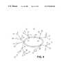
- FIG. 4shows a generalized functional block diagram of a network 100 , incorporating an embodiment of the invention.
- network 100includes a number of nodes 102 , which are interconnected to form a ring 104 .
- the nodes 102 on the ring 104are sometimes referred to herein as “ring nodes.”
- ring 104is formed with dual rings, which will be described in more detail later.
- Coupled to many of the ring nodes 102are other nodes 106 , sometimes referred to herein as “multiplexing nodes.”
- ring nodes 102 and multiplexing nodes 104are substantially the same.
- both types of nodesare denoted by a circle, “ ⁇ ”, and are generically referred to herein as “Quality of Service Nodes” or “QoS Nodes.”
- the QoS Nodes 102 , 106include ethernet interfaces that operate at 1 Gbps. In other embodiments, however, the nodes may operate at a different rate (e.g., 10 Mbps, 100 Mbps, OC12, OC48, OC96, OC192). Moreover, some QoS Nodes may operate at one rate while other QoS Nodes operate at a second rate. Hence, the actual rates for either of the types of QoS Nodes are not intended to be restricted by the invention nor are the interfaces utilized.
- the actual links between the QoS Nodescan be formed in any manner known to those of skill in the art.
- the links interconnecting the QoS Nodescan be built from single or multiple twisted wire pairs, optical fibers, or coaxial cable.
- the linkscan be radio links, or even free space infrared links.
- the protocol used by the linksmay be based on Gigabit Ethernet, ATM, WDM, SONET, or other technology.
- FIG. 4further illustrates the plurality of packet switches 108 , denoted with a square symbol, “ ⁇ ”.
- the packet switchesare similar to those known by persons of ordinary skill in the art. For instance, packet switches can be routers with standard ethernet interfaces such as those made by Cisco Systems or Nortel Networks.
- the packet switchesare attached either directly to ring 104 via a ring node 102 , or indirectly to the ring 104 via a multiplexing node 106 .
- Each packet switch 108is in turn coupled to a number of LANs or other subnets 110 , denoted by an “X” indicator (only a few subnets are illustrated).
- packet switchesdenote standard packet switches, which are known in the art and include devices such as routers. Ring nodes 102 and multiplexing nodes 106 , although technically packet switches (since they route incoming packets to output ports), are distinguishable from standard packet switches, and are referred to herein as “Quality of Service Nodes” or “QoS Nodes.”
- a minimum quality of service(a minimum bandwidth) is provided between selected pairs of packet switches, such as from A to B, B to A, or from A to C.
- the quality of service for a particular packet switch pairis referred to herein as a Service Level Agreement, or SLA.
- SLAService Level Agreement
- Each SLAincludes at least three elements: a source packet switch, a destination packet switch, and a minimum data rate for data transfers between the two packet switches.
- an SLAmay be, for example, a 128-kbps connection between A and B.
- the packets received at each QoS Node 102 , 106 from a packet switch 108are ethernet frames, which specify the Layer 2 address of the source packet switch and the Layer 2 address of the destination packet switch.
- a standard ethernet frameis shown in FIG. 5.
- a frameincludes a preamble field, a start-of-frame (SOF) field, a destination address field, a source address field, a length of data field, a data field, a pad field, and a checksum field.
- SOFstart-of-frame
- ethernet framesare frequently referred to herein, other types of packets could be utilized in other embodiments of the invention. Hence, ethernet packets are used for purposes of illustration only, and such illustration is not intended to limit the scope of the invention.
- a first embodiment of a node 102 , 106is shown in FIG. 6 .
- packetse.g., ethernet frames
- classifier 304classifies each packet in accordance with an SLA. To do so, classifier 304 reads at least the source and destination identifier of the packet to be classified, for instance, Layer 2 ethernet frame addresses. The classifier 304 then correlates the pair of identifiers with a corresponding SLA.
- such source and destination identifiersare physical addresses, while in other embodiments such source and destination addresses may be composed of other information.
- other embodiments of the inventionmay utilize other information for packet classification.
- the type of applicatione.g., e-mail
- the information used for classifying packetsis referred to herein as “classification information.”
- the packetis placed into a FIFO-type buffer 306 - 312 that corresponds to the SLA, forming a queue of packets for the SLA.
- the packetsdo not need to be reformatted or modified in any way.
- the packetsare scheduled for transmission by scheduler 316 and placed in an appropriate output port 317 .
- scheduler 316For purposes of continued discussion, the scheduling methods used herein are discussed with reference only to a single output port, although it is to be understood that a QoS Node could have more than one output port.
- a scheduler in one embodiment of the inventionuses the Deficit Round Robin (DRR) scheduling method described previously with respect to FIG. 3 .
- DRRDeficit Round Robin
- the bandwidth for the particular data streamis greater than or equal to the rate (R) of the link times the weight (W) for a particular data stream divided by the sum of weights.
- RW ⁇ ( i ) W ⁇ ( 1 ) + W ⁇ ( 2 ) + ... + W ⁇ ( N ) ⁇ bandwidthRW ⁇ ( i ) W ⁇ ( 1 ) + W ⁇ ( 2 ) + ... + W ⁇ ( N ) ⁇ bandwidth . Therefore, using the DRR scheduling method, a minimum quality of service for each SLA can be guaranteed.
- DRRmay introduce delay and/or jitter into the bit stream, particularly when there are many queues.
- bits from the other SLA'smust wait.
- no bitswill be sent from SLA- 1 until bits from all of the other participating SLA's have been sent. Such wait times may be unacceptable for some applications.
- DGRDeficit Golden Ratio
- An integer P(k)is then set to equal the integer part of W(k)/1000. Since the average packet length in Internet Protocol (IP) applications is about 1000 bits, P(k) is approximately the average number of packets of SLA-k that DRR would serve in one cycle. In other embodiments, P(k) can be found using a denominator other than 1000, for instance, if an average packet length is a different value.
- IPInternet Protocol
- the packet sequenceis chosen so that there are P(k) packets from SLA-k in the sequence.
- the sequenceis selected so that the packets from each SLA are distributed in the sequence.
- the sequenceis constructed as follows.
- the successive decimal parts of the first P multiples of 0.62are calculated by the scheduler.
- the schedulernotes that SLA- 1 still has W( 1 ) ⁇ Q( 1 ) credits.
- the schedulerthen continues this procedure with the other SLAs in the DGR sequence, e.g., in Table 3 above, SLA- 3 , then SLA-1, and so on, sending a packet from each SLA unless the SLA has been dropped from the cycle.
- the schedulerstarts again from the beginning of the sequence and continues to perform the same procedure until all of the SLAs have exhausted all of their credits (i.e., until all SLA's have been dropped from the cycle).
- the cycleends, and the scheduler starts a new cycle with the credits W(i) replaced by W(i)-D(i).
- another new cyclestarts where the credits allocated to each SLA are W(i)-D′(i), and so on.
- An example output streamis shown in FIG. 7 .
- the DGR scheduling methodresults in smoother traffic and smaller delays, but still guarantees the bandwidth reserved for the SLA.
- classifier and scheduler described abovecan be implemented in hardware, software, and/or firmware, or any combination thereof.
- FIG. 8A second embodiment of a QoS Node 102 , 106 is shown in FIG. 8 .
- an “aggregate queue,”is used for all SLA's in FIG. 8 .
- the classifier 404maintains a single first-in, first-out queue in buffer 406 for all the SLA's.
- the packetsare placed in the buffer 406 in the order of their arrival at the QoS Node.
- the packetsare only placed by classifier 404 into the queue if a scheduler allows such placement.
- Such a scheduleroperates in accordance with a scheduling method referred to herein as “SLA Early Discard,” and represents a new form of statistical multiplexing.
- M(k)some integer weight
- the packet queuecontains about M( 1 )+M( 2 )+ . . . +M(k) packets.
- the linktransmits a fraction M ⁇ ( k ) M ⁇ ( 1 ) + M ⁇ ( 2 ) + ... + M ⁇ ( N ) of its packets from SLA-k. Therefore, SLA-k is guaranteed the fraction listed above of the total link bandwidth.
- packetsare only discarded after monitoring the aggregate queue, whereas in ATM, packets are discarded solely on the basis of the source they are form. In ATM, regardless of whether other resources are required by other data streams, packets are discarded upon reaching a threshold for that source during a given time interval. In contrast, the SLA early discard method of the present invention only discards packets if they exceed a percentage of the aggregate queue.
- classifier and scheduler for a node described abovecan be implemented in hardware, software, and/or firmware, or any combination thereof.
- the SLA'scan be equated to virtual leased lines.
- minimum bandwidthcan be guaranteed between pairs of packet switches.
- such guaranteesare provided while still utilizing standard packet switches and without modifying router software.
- one embodiment of the inventionis compatible with packet switches that include standard Ethernet interfaces.
- the frame structure for Ethernet (or other) packetsdoes not need to be modified as they would for SONET and ATM, causing the system to appear to the packet switch as a shared Ethernet.
- a system in accordance with the inventionrequire complex hardware and software akin to that required for ATM.
- each nodewill transmit packets for each SLA at a minimum rate. Nonetheless, the actual rate provided can actually be faster than the minimum guaranteed rate. But if such faster service is provided, the capacity of some links in the network may be exceeded.
- the QoS Nodesmay additionally implement a congestion control method herein referred to as Distributed Back Pressure (DBP).
- DBPDistributed Back Pressure
- each QoS Nodemonitors whether any of its SLA's are congested and maintains a list of all congested SLA's. Such a list is represented in FIG. 6 at 318 and in FIG. 8 at 418 .
- the status of an SLAis marked as “congested” when the occupancy of the queue corresponding to that SLA exceeds some threshold H.
- the statusis reset to “non-congested” when the occupancy of the queue corresponding to the SLA falls below the threshold H.
- the QoS NodePeriodically, the QoS Node sends a control message to its neighboring QoS Nodes, including a current list of all congested SLA's. Each QoS Node uses these control messages to maintain and update its own list of the congested SLA's.
- the scheduler ( 316 in FIG. 6 ) for each QoS Nodethen skips (does not schedule any packets from) every SLA queue marked as congested.
- the QoS Nodecan simply reduce the rate of transmission for the SLA, e.g., to the minimum guaranteed rates.
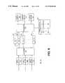
- FIG. 10shows three streams A, B, C transmitting with rates 0.2, 0.6, and 0.2, respectively, and that share an output port of the first QoS Node 702 that has an output port rate 1.
- the SLAs for A, B, and Chave minimum rates of 0.2 each.
- the schedulerlets stream B be overactive.
- the queue for SLA-B in the second QoS Node 703gets saturated: the five SLAs in node 703 each get a service rate of 0.2 but the input of the queue for the SLA-B in the second QoS Node 703 has rate 0.6.
- the second QoS Node 703sends a message to QoS Node 702 indicating that QoS Node 702 should stop transmitting packets from SLA-B or reduce the transmission rate to the minimum guaranteed rate, e.g., 0.6.
- backpressureis asserted at the source of SLA-B. Only those SLA queues that are congested are switched off or rate reduced—not the entire QoS Node. In other words, the SLAs for A and C will continue to transmit.
- conventional network flow control techniquesactually stops the entire flow from a switch when congestion is detected.
- DBPcan still be utilized.
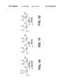
- the embodiment of a QoS Node in FIG. 8provides at least a minimum bandwidth for each SLA. Still, the bandwidth provided is permitted to exceed the minimum, which could cause congestion in the input queues of other QoS Nodes.
- the congested QoS Nodesends a STOP message to the upstream QoS Node indicating that the upstream QoS Node should stop transmitting.
- the queue at the congested QoS Nodeempties and the now uncongested QoS Node informs the source QoS Node to start transmitting again.
- the congested QoS Nodecan inform the source QoS Node to serve the aggregate SLA's at a lower rate, e.g. at the minimum guaranteed rate.
- FIG. 11shows DBP when the data streams A, B, and C share a single queue in QoS Node 703 .
- the SLA's for A, B, and Chave minimum rates of 0.2, although the scheduler in QoS Node 702 has allowed SLA-B to transmit at 0.6.
- QoS Node 703sends a STOP message to node 702 , turning off all the streams from A, B, and C.
- QoS Node 703indicates that the streams can resume.
- A, B, Ctogether get a service rate in QoS Node 702 equal to 0.6. This total rate is divided equally between A, B, and C which then get 0.2 each.
- FIG. 10shows DBP when the data streams A, B, and C share a single queue in QoS Node 703 .
- the SLA's for A, B, and Chave minimum rates of 0.2, although the scheduler in QoS Node 702 has allowed SLA-B to transmit at 0.6.
- QoS Node 703when the SLAs A, B, and C share a queue in QoS Node 703 , QoS Node 703 sends a message to QoS Node 702 to serve at its guaranteed minimum aggregate rate (0.6) instead of turning off.
- each QoS Node in some embodiments of the inventioncan also implement an internal flow control.
- the scheduler 316marks the SLA's that should be sent to that buffer as congested and skips those queues.
- the QoS Nodestops transferring packets from the input buffers 302 to the SLA queue.
- the ethernet interfacesends a signal to appropriate packet switches to stop sending packets.
- DBPin accordance with the invention exercises a finer congestion control than conventional flow control that shuts off a link completely instead of stopping only the overly active data streams.
- a pair of bandwidth managers 112are included in the network as shown in FIG. 4 with a “ ⁇ ” symbol.
- the bandwidth managersdetermine if a new SLA can be accepted.
- two bandwidth managers 112are provided attached to the ring at different ring nodes 102 .
- the bandwidth managers 112monitor the current ring configuration and network topology and keep track of the bandwidth reserved between any two pairs of packet switches. Using this information, the bandwidth managers compute both the bandwidth utilized and available on each segment of the ring. When a request for a new SLA is made, the bandwidth manager uses these computations and determines if the new SLA can be accommodated.
- bandwidth managersare, in one embodiment, computers operating software to perform the management functions described above.
- a pair of bandwidth managersare provided for reliability.
- Other embodiments of the inventioncould have one or more bandwidth managers.
- an additional protocolis implemented, referred to herein as a “Tail-Safe Management Protocol” (FSMP).
- FSMPTiil-Safe Management Protocol
- the FSMPprotects the network 100 against failure of the links connecting the QoS Nodes as well as failure of the QoS Nodes themselves.
- a network 100operates with FSMP by including a self-healing physical layer.
- FSMPWhen a failure occurs in part of the ring, the ring reconfigures itself to avoid the failure.
- FSMPdetects the reconfiguration and initializes a network status update.
- self-healingis well-known in the art such as in networks using SONET or FDDI protocols.
- ring 104is a dual ring, where one ring transmits packets in a clockwise direction and a second ring transmits packets in a counter-clockwise direction.
- the networkreconfigures itself from a dual ring into a single logical working ring.
- Other systems, such as SONET,have also used dual ring configurations. SONET however, uses its dual rings to simultaneously send two versions of the bit stream: one version clockwise and the other counter-clockwise. While this strategy ensures reliability, it is also very wasteful of valuable bandwidth.
- FIGS. 13 a and 13 billustrates ring nodes 1 . . . M.
- each QoS Node on the ringmonitors its incoming data streams from the dual links.
- the ringallows transmission in either direction (clockwise or counter-clockwise) in an embodiment of the invention for both robustness and to allow the shortest path to be chosen for communication between any two QoS Nodes, which helps enable the minimum rates of the SLAs to be met.
- SONETonly one version of the packet is sent. But if, for instance, the incoming stream to node M stops on the link from node M- 1 , as shown in FIG.
- QoS Node Msends a message to QoS Node 1 .
- QoS Node 1confirms reception of the message to QoS Node M.
- QoS Node 1then sends a message to QoS Node 2 , which confirms receipt of the message, and the process continues.
- QoS Node M- 1sends a message to QoS Node M, QoS Node M will not receive the message and, hence, QoS Node M- 1 will not receive a confirming message.
- QoS Node MWhen QoS Node M does not confirm the message, then failure of the links between QoS Node M- 1 and QoS Node M is confirmed.
- the QoS Nodesthen reconfigure the rings as shown in FIG. 13 b , such that a single ring is formed using the dual links.
- the QoS Nodesalso initiate a network status update that triggers an alarm for the network bandwidth manager to re-run its calculations to determine whether the reconfiguration has resulted in any bandwidth reservations being violated (i.e., the question is asked of whether the network can still support the rate requirements of all the SLAs).
- TCPTransmission Control Protocol
- some embodiments of the inventionattach a time stamp to a packet as it enters a QoS Node from a packet switch. Once the packet has arrived at the QoS Node immediately prior to the destination packet switch, the packet goes through a playback buffer to ensure that the packet leaves T seconds after it entered the first QoS Node.
- the QoS Nodeskeep their clocks synchronized by using a standard clock synchronization method that will be known to those of skill in the art. In this manner, all connections are designated a minimum delay, preventing speedy connections from usurping excessive bandwidth.
- a system and methodhas now been described that allows efficient operations of a communications network that includes bandwidth guarantees. Some embodiments of the invention further provide delay guarantees as well as regulate data flow and provide network reliability.
- a system in accordance with the inventionis not only high performance, but also economical, simple, and flexible, while remaining compatible with much of the hardware and software already in place, particularly hardware and software for routers and ethernet interfaces.
- the SLAs for a system and method in accordance with the inventioncan be equated to virtual leased lines.
- an embodiment of the inventionmay be particularly useful in a metropolitan area network (MAN).
- MANmetropolitan area network
Landscapes
- Engineering & Computer Science (AREA)
- Computer Networks & Wireless Communication (AREA)
- Signal Processing (AREA)
- Data Exchanges In Wide-Area Networks (AREA)
Abstract
Description
of the transmission rate of the link. So, using TDM, a link with transmission rate R is capable of carrying data streams with rate R(1), . . . , R(N) provided that R(1)+ . . . + R(N) is less than R. Therefore, a circuit-switched network with TDM provides a guaranteed bandwidth to a connection from the source of the connection to its destination.
of the transmission rate for the link. Moreover, if some data streams do not need their guaranteed allocation, then the other connections can utilize the unused resources and will do so automatically. Many variations of DRR are known in the art, including Weighted Fair Queuing (WFQ), Generalized Processor Sharing (GPS), and Class Based Queuing (CBQ).
Therefore, using the DRR scheduling method, a minimum quality of service for each SLA can be guaranteed.
| TABLE 1 | |||
| Multiple | Decimal Part | ||
| 0 | 0.00 | ||
| 1 | 0.62 | ||
| 2 | 0.24 | ||
| 3 | 0.86 | ||
| 4 | 0.48 | ||
| 5 | 0.10 | ||
The scheduler sequentially groups these multiples into groups corresponding to each SLA-k, where each group has P(k) sequential multiples. Continuing the above example, since P(1)=3, then SLA-1 is designated the first three multiples, SLA-2 will receive the next one multiple since P(2)=1, and since P(3)=2, SLA-3 receives the last two multiples. The designated decimal parts of the multiples are shown in Table 2 below:
| TABLE 2 | |
| Designated Decimal Parts of N | |
| SLA | multiples of 0.62 |
| SLA-1 | 0, 0.62, 0.24 |
| SLA-2 | 0.86 |
| SLA-3 | 0.48, 0.10 |
To determine the packet sequence, the decimal parts are placed by the scheduler in increasing order, where the designated SLA-k remains correlated to the decimal part. For the example above, such ordering is shown in Table 3:
| TABLE 3 | |||
| Decimal Part | SLA | ||
| 0.00 | SLA-1 | ||
| 0.10 | SLA-3 | ||
| 0.24 | SLA-1 | ||
| 0.48 | SLA-3 | ||
| 0.62 | SLA-1 | ||
| 0.86 | SLA-2 | ||
The scheduler will output packets from the SLAs according to the re-ordered decimal parts. Hence, Table 3 indicates that the packet sequence output by the scheduler in our example should be from {1, 3, 1, 3, 1, 2}, where the numbers inside the brackets correspond to SLA numbers.
of its packets from SLA-k. Therefore, SLA-k is guaranteed the fraction listed above of the total link bandwidth. Further, packets are only discarded after monitoring the aggregate queue, whereas in ATM, packets are discarded solely on the basis of the source they are form. In ATM, regardless of whether other resources are required by other data streams, packets are discarded upon reaching a threshold for that source during a given time interval. In contrast, the SLA early discard method of the present invention only discards packets if they exceed a percentage of the aggregate queue.
Claims (15)
Priority Applications (2)
| Application Number | Priority Date | Filing Date | Title |
|---|---|---|---|
| US09/189,819US6970424B2 (en) | 1998-11-10 | 1998-11-10 | Method and apparatus to minimize congestion in a packet switched network |
| PCT/US1999/023627WO2000028706A1 (en) | 1998-11-10 | 1999-10-13 | Method and apparatus to minimize congestion in a packet switched network |
Applications Claiming Priority (1)
| Application Number | Priority Date | Filing Date | Title |
|---|---|---|---|
| US09/189,819US6970424B2 (en) | 1998-11-10 | 1998-11-10 | Method and apparatus to minimize congestion in a packet switched network |
Publications (2)
| Publication Number | Publication Date |
|---|---|
| US20030133406A1 US20030133406A1 (en) | 2003-07-17 |
| US6970424B2true US6970424B2 (en) | 2005-11-29 |
Family
ID=22698900
Family Applications (1)
| Application Number | Title | Priority Date | Filing Date |
|---|---|---|---|
| US09/189,819Expired - LifetimeUS6970424B2 (en) | 1998-11-10 | 1998-11-10 | Method and apparatus to minimize congestion in a packet switched network |
Country Status (2)
| Country | Link |
|---|---|
| US (1) | US6970424B2 (en) |
| WO (1) | WO2000028706A1 (en) |
Cited By (22)
| Publication number | Priority date | Publication date | Assignee | Title |
|---|---|---|---|---|
| US20020087763A1 (en)* | 1999-05-12 | 2002-07-04 | Wendorff Wilhard Von | Communication sytem with a communication bus |
| US20020136228A1 (en)* | 2001-03-21 | 2002-09-26 | Rei Miyamoto | Queue allocation system and queue allocation method of a packet exchanger |
| US20020172205A1 (en)* | 2001-05-07 | 2002-11-21 | Tagore-Brage Jens P. | System and a method for processing data packets or frames |
| US20030026257A1 (en)* | 2001-04-30 | 2003-02-06 | Nokia Corporation | Network |
| US20030065769A1 (en)* | 2000-02-18 | 2003-04-03 | Kryskow Joseph M. | Real time mesh measurement system stream latency and jitter measurements |
| US20030115355A1 (en)* | 2001-12-18 | 2003-06-19 | Andiamo Systems, Inc. | Methods and apparatus for network congestion control |
| US20030123393A1 (en)* | 2002-01-03 | 2003-07-03 | Feuerstraeter Mark T. | Method and apparatus for priority based flow control in an ethernet architecture |
| US20030195983A1 (en)* | 1999-05-24 | 2003-10-16 | Krause Michael R. | Network congestion management using aggressive timers |
| US20030210653A1 (en)* | 2002-05-08 | 2003-11-13 | Worldcom, Inc. | Systems and methods for performing selective flow control |
| US20040042460A1 (en)* | 2002-06-24 | 2004-03-04 | Stefan Gruhl | Quality of service (QoS) scheduling for packet switched, in particular GPRS/EGPRS, data services |
| US20050018611A1 (en)* | 1999-12-01 | 2005-01-27 | International Business Machines Corporation | System and method for monitoring performance, analyzing capacity and utilization, and planning capacity for networks and intelligent, network connected processes |
| US20060007856A1 (en)* | 2004-06-07 | 2006-01-12 | Nokia Corporation | Backpressure method on multiplexed links |
| US20070115824A1 (en)* | 2005-11-18 | 2007-05-24 | Sutapa Chandra | Selective flow control |
| US7305431B2 (en)* | 2002-09-30 | 2007-12-04 | International Business Machines Corporation | Automatic enforcement of service-level agreements for providing services over a network |
| US20080005354A1 (en)* | 2002-08-16 | 2008-01-03 | Kryskow Joseph M Jr | Real time mesh measurement systen stream latency and jitter measurements |
| US7590058B1 (en)* | 2003-12-09 | 2009-09-15 | At&T Intellectual Property Ii, L.P. | Method and apparatus for controlling the quality of service of voice and data services over variable bandwidth access networks |
| US7734808B1 (en)* | 2001-12-18 | 2010-06-08 | Cisco Technology, Inc. | End-to-end congestion control in a Fibre Channel network |
| US7876681B2 (en) | 2002-05-24 | 2011-01-25 | Verizon Business Global Llc | Systems and methods for controlling network-bound traffic |
| US20110199925A1 (en)* | 2000-09-06 | 2011-08-18 | Juniper Networks, Inc. | Packet switching equipment and switching control method |
| US9015471B2 (en) | 2000-07-10 | 2015-04-21 | Alterwan, Inc. | Inter-autonomous networking involving multiple service providers |
| US20190028392A1 (en)* | 2017-07-18 | 2019-01-24 | Level 3 Communications, Llc | Systems and methods for enhanced autonegotiation |
| US10965572B2 (en) | 2017-05-01 | 2021-03-30 | Bank Of America Corporation | Data transfer control |
Families Citing this family (51)
| Publication number | Priority date | Publication date | Assignee | Title |
|---|---|---|---|---|
| US6600908B1 (en) | 1999-02-04 | 2003-07-29 | Hark C. Chan | Method and system for broadcasting and receiving audio information and associated audio indexes |
| US7245707B1 (en)* | 1999-03-26 | 2007-07-17 | Chan Hark C | Data network based telephone messaging system |
| FI108978B (en)* | 1999-11-25 | 2002-04-30 | Datatie Ab Oy | Method for checking the channels in a transmission path |
| US20020009088A1 (en)* | 1999-11-30 | 2002-01-24 | Donaghey Robert J. | Systems and methods for negotiating virtual circuit paths in packet switched networks |
| US20010030969A1 (en)* | 1999-11-30 | 2001-10-18 | Donaghey Robert J. | Systems and methods for implementing global virtual circuits in packet-switched networks |
| US7106747B2 (en)* | 1999-11-30 | 2006-09-12 | Level 3 Communications, Llc | Systems and methods for implementing second-link routing in packet switched networks |
| US6731645B1 (en)* | 2000-02-29 | 2004-05-04 | International Business Machines Corporation | Methods, switches, systems, and computer program products for fair transmission of data received at multiple inputs in the order received in a queued memory switch |
| US6981054B1 (en)* | 2000-06-06 | 2005-12-27 | Advanced Micro Devices, Inc. | Flow control arrangement in a network switch based on priority traffic |
| US7236491B2 (en)* | 2000-11-30 | 2007-06-26 | Industrial Technology Research Institute | Method and apparatus for scheduling for packet-switched networks |
| US6947380B1 (en)* | 2000-12-01 | 2005-09-20 | Cisco Technology, Inc. | Guaranteed bandwidth mechanism for a terabit multiservice switch |
| US7130267B1 (en) | 2000-12-29 | 2006-10-31 | Cisco Technology, Inc. | System and method for allocating bandwidth in a network node |
| US20020097678A1 (en)* | 2001-01-23 | 2002-07-25 | Bisher James A. | Method and apparatus for bandwidth management associated with misbehaving sessions |
| FI110466B (en)* | 2001-03-22 | 2003-01-31 | Sonera Oyj | Procedure for checking the data transmission capacity |
| US7450510B1 (en) | 2001-04-19 | 2008-11-11 | Cisco Technology, Inc. | System and method for distributing guaranteed bandwidth among service groups in a network node |
| US8228797B1 (en)* | 2001-05-31 | 2012-07-24 | Fujitsu Limited | System and method for providing optimum bandwidth utilization |
| KR100431191B1 (en)* | 2001-12-03 | 2004-05-12 | 주식회사 케이티 | An apparatus and method for scheduling packets by using a round robin based on credit |
| US7289525B2 (en)* | 2002-02-21 | 2007-10-30 | Intel Corporation | Inverse multiplexing of managed traffic flows over a multi-star network |
| US7248594B2 (en)* | 2002-06-14 | 2007-07-24 | Intel Corporation | Efficient multi-threaded multi-processor scheduling implementation |
| SE0203362D0 (en)* | 2002-11-13 | 2002-11-13 | Reddo Networks Ab | A method and apparatus for transferring data packets in a router |
| US7492760B1 (en)* | 2003-03-31 | 2009-02-17 | Pmc-Sierra, Inc. | Memory egress self selection architecture |
| US7519725B2 (en) | 2003-05-23 | 2009-04-14 | International Business Machines Corporation | System and method for utilizing informed throttling to guarantee quality of service to I/O streams |
| US7529247B2 (en) | 2003-09-17 | 2009-05-05 | Rivulet Communications, Inc. | Empirical scheduling of network packets |
| US7468948B2 (en) | 2003-09-17 | 2008-12-23 | Steven A Rogers | Empirical scheduling of network packets using coarse and fine testing periods |
| US7339923B2 (en) | 2003-10-31 | 2008-03-04 | Rivulet Communications, Inc. | Endpoint packet scheduling system |
| US7508813B2 (en) | 2003-11-25 | 2009-03-24 | Rivulet Communications | Local area network contention avoidance |
| CA2509307A1 (en)* | 2004-06-23 | 2005-12-23 | Tundra Semiconductor Corporation | Switching fabric bridge |
| US7428239B1 (en)* | 2004-08-26 | 2008-09-23 | Software Site Applications, Limited Liability Company | Apparatus and method for priority queuing with segmented buffers |
| US7453885B2 (en) | 2004-10-13 | 2008-11-18 | Rivulet Communications, Inc. | Network connection device |
| EP1847071A4 (en)* | 2005-01-26 | 2010-10-20 | Internet Broadcasting Corp B V | MULTI-DIFFUSION IN LAYERS AND EXACT ATTRIBUTION OF BANDWIDTH AND PRIORIZATION OF PACKETS |
| DE102005009852B3 (en)* | 2005-03-03 | 2006-06-29 | Siemens Ag | Device for receiving and managing medical graphic data has one or more computer devices whereby at least one personal computer and image requesting activity of personal computer and loading time form outgoing network traffic at server |
| US9185036B2 (en)* | 2005-03-23 | 2015-11-10 | Alcatel Lucent | Method and apparatus for flow control of data in a network |
| US7489690B2 (en)* | 2005-08-12 | 2009-02-10 | Cellco Partnership | Integrated packet latency aware QoS scheduling algorithm using proportional fairness and weighted fair queuing for wireless integrated multimedia packet services |
| US8509062B2 (en)* | 2006-08-07 | 2013-08-13 | Ciena Corporation | Smart ethernet edge networking system |
| US7729274B2 (en)* | 2006-03-31 | 2010-06-01 | Ciena Corporation | Smart ethernet mesh edge device |
| US9621375B2 (en)* | 2006-09-12 | 2017-04-11 | Ciena Corporation | Smart Ethernet edge networking system |
| US8218445B2 (en)* | 2006-06-02 | 2012-07-10 | Ciena Corporation | Smart ethernet edge networking system |
| US8363545B2 (en)* | 2007-02-15 | 2013-01-29 | Ciena Corporation | Efficient ethernet LAN with service level agreements |
| US20080049760A1 (en)* | 2006-08-24 | 2008-02-28 | Gilles Bergeron | Oversubscription in broadband network |
| US20090188561A1 (en)* | 2008-01-25 | 2009-07-30 | Emcore Corporation | High concentration terrestrial solar array with III-V compound semiconductor cell |
| JP5534711B2 (en)* | 2009-05-01 | 2014-07-02 | キヤノン株式会社 | Information processing apparatus, information processing method, and program |
| US8774003B1 (en) | 2010-04-28 | 2014-07-08 | Adtran, Inc. | Systems and methods for providing service admission control in telecommunication networks |
| JP5948345B2 (en) | 2011-01-11 | 2016-07-06 | エイ10 ネットワークス インコーポレイテッドA10 Networks, Inc. | Virtual application delivery chassis system |
| GB201101709D0 (en)* | 2011-02-01 | 2011-03-16 | Transpacket As | A method and a node arrangement for optimizing traffic processing in integrated hybrid networks |
| US9154577B2 (en) | 2011-06-06 | 2015-10-06 | A10 Networks, Inc. | Sychronization of configuration file of virtual application distribution chassis |
| WO2013007180A1 (en)* | 2011-07-08 | 2013-01-17 | 华为技术有限公司 | Method, device and system for network congestion control |
| US10742559B2 (en) | 2014-04-24 | 2020-08-11 | A10 Networks, Inc. | Eliminating data traffic redirection in scalable clusters |
| US9961130B2 (en) | 2014-04-24 | 2018-05-01 | A10 Networks, Inc. | Distributed high availability processing methods for service sessions |
| US10318288B2 (en) | 2016-01-13 | 2019-06-11 | A10 Networks, Inc. | System and method to process a chain of network applications |
| CN106992939B (en)* | 2017-05-16 | 2023-10-10 | 新疆安迪星通信息科技有限公司 | Dynamic learning system and method for QoS flow control threshold of satellite IP network |
| US12041449B2 (en)* | 2020-04-10 | 2024-07-16 | Qualcomm Incorporated | Method and apparatus for verifying mobile device communications |
| CN114828081B (en)* | 2022-03-30 | 2024-09-20 | 天津大学 | Cooperative hybrid congestion control method based on path recovery |
Citations (26)
| Publication number | Priority date | Publication date | Assignee | Title |
|---|---|---|---|---|
| US5313454A (en) | 1992-04-01 | 1994-05-17 | Stratacom, Inc. | Congestion control for cell networks |
| WO1994014263A1 (en) | 1992-12-14 | 1994-06-23 | Nokia Telecommunications Oy | A method for congestion management in a frame relay network and a node in a frame relay network |
| US5359592A (en) | 1993-06-25 | 1994-10-25 | Stratacom, Inc. | Bandwidth and congestion control for queue channels in a cell switching communication controller |
| US5361255A (en) | 1991-04-29 | 1994-11-01 | Dsc Communications Corporation | Method and apparatus for a high speed asynchronous transfer mode switch |
| US5440549A (en) | 1993-04-22 | 1995-08-08 | Washington University | Broadband multi-channel switch with multicasting capability |
| US5485455A (en) | 1994-01-28 | 1996-01-16 | Cabletron Systems, Inc. | Network having secure fast packet switching and guaranteed quality of service |
| US5497375A (en)* | 1994-01-05 | 1996-03-05 | Motorola, Inc. | Device and method for ATM end system cell flow regulation |
| US5519698A (en) | 1992-05-20 | 1996-05-21 | Xerox Corporation | Modification to a reservation ring mechanism for controlling contention in a broadband ISDN fast packet switch suitable for use in a local area network |
| US5675576A (en) | 1995-06-05 | 1997-10-07 | Lucent Technologies Inc. | Concestion control system and method for packet switched networks providing max-min fairness |
| US5734486A (en) | 1994-11-04 | 1998-03-31 | France Telecom | Optical packet switching system |
| US5742772A (en) | 1995-11-17 | 1998-04-21 | Lucent Technologies Inc. | Resource management system for a broadband multipoint bridge |
| US5812545A (en) | 1996-01-04 | 1998-09-22 | Orion Atlantic, L.P. | Full mesh satellite-based multimedia networking system |
| EP0868058A1 (en) | 1997-03-27 | 1998-09-30 | Lucent Technologies Inc. | Apparatus and method for template-based scheduling using regularity measure lower bounds |
| WO1998045976A2 (en) | 1997-04-04 | 1998-10-15 | Ascend Communications, Inc. | Hierarchical packet scheduling method and apparatus |
| US6058102A (en)* | 1997-11-07 | 2000-05-02 | Visual Networks Technologies, Inc. | Method and apparatus for performing service level analysis of communications network performance metrics |
| US6097697A (en)* | 1998-07-17 | 2000-08-01 | Sitara Networks, Inc. | Congestion control |
| US6167028A (en)* | 1998-06-01 | 2000-12-26 | Motorola, Inc. | Methods and apparatus for facilitating transmission of cells having multiple priorities in a cell relay network |
| US6192406B1 (en)* | 1997-06-13 | 2001-02-20 | At&T Corp. | Startup management system and method for networks |
| US6208619B1 (en)* | 1997-03-27 | 2001-03-27 | Kabushiki Kaisha Toshiba | Packet data flow control method and device |
| US6324165B1 (en)* | 1997-09-05 | 2001-11-27 | Nec Usa, Inc. | Large capacity, multiclass core ATM switch architecture |
| US6333917B1 (en)* | 1998-08-19 | 2001-12-25 | Nortel Networks Limited | Method and apparatus for red (random early detection) and enhancements. |
| US6414939B1 (en)* | 1997-09-05 | 2002-07-02 | Kabushiki Kaisha Toshiba | Router apparatus and control-frame processing method |
| US6438138B1 (en)* | 1997-10-01 | 2002-08-20 | Nec Corporation | Buffer controller incorporated in asynchronous transfer mode network for changing transmission cell rate depending on duration of congestion and method for controlling thereof |
| US6452905B1 (en)* | 1995-03-08 | 2002-09-17 | British Telecommunications Public Limited Company | Broadband switching system |
| US6452915B1 (en)* | 1998-07-10 | 2002-09-17 | Malibu Networks, Inc. | IP-flow classification in a wireless point to multi-point (PTMP) transmission system |
| US6463036B2 (en)* | 1996-01-11 | 2002-10-08 | Hitachi, Ltd. | ATM communication apparatus and method of controlling congestion in a communication network using the ATM communication apparatus |
- 1998
- 1998-11-10USUS09/189,819patent/US6970424B2/ennot_activeExpired - Lifetime
- 1999
- 1999-10-13WOPCT/US1999/023627patent/WO2000028706A1/enactiveApplication Filing
Patent Citations (29)
| Publication number | Priority date | Publication date | Assignee | Title |
|---|---|---|---|---|
| US5361255A (en) | 1991-04-29 | 1994-11-01 | Dsc Communications Corporation | Method and apparatus for a high speed asynchronous transfer mode switch |
| US5313454A (en) | 1992-04-01 | 1994-05-17 | Stratacom, Inc. | Congestion control for cell networks |
| US5519698A (en) | 1992-05-20 | 1996-05-21 | Xerox Corporation | Modification to a reservation ring mechanism for controlling contention in a broadband ISDN fast packet switch suitable for use in a local area network |
| WO1994014263A1 (en) | 1992-12-14 | 1994-06-23 | Nokia Telecommunications Oy | A method for congestion management in a frame relay network and a node in a frame relay network |
| US5526352A (en) | 1993-04-22 | 1996-06-11 | Washington University | Integrated low complexity broadband multi-channel switch |
| US5440549A (en) | 1993-04-22 | 1995-08-08 | Washington University | Broadband multi-channel switch with multicasting capability |
| US5359592A (en) | 1993-06-25 | 1994-10-25 | Stratacom, Inc. | Bandwidth and congestion control for queue channels in a cell switching communication controller |
| US5497375A (en)* | 1994-01-05 | 1996-03-05 | Motorola, Inc. | Device and method for ATM end system cell flow regulation |
| US5485455A (en) | 1994-01-28 | 1996-01-16 | Cabletron Systems, Inc. | Network having secure fast packet switching and guaranteed quality of service |
| US5491694A (en) | 1994-01-28 | 1996-02-13 | Cabletron Systems, Inc. | System and method for allocating a shared resource among competing devices |
| US5790546A (en) | 1994-01-28 | 1998-08-04 | Cabletron Systems, Inc. | Method of transmitting data packets in a packet switched communications network |
| US5734486A (en) | 1994-11-04 | 1998-03-31 | France Telecom | Optical packet switching system |
| US6452905B1 (en)* | 1995-03-08 | 2002-09-17 | British Telecommunications Public Limited Company | Broadband switching system |
| US5675576A (en) | 1995-06-05 | 1997-10-07 | Lucent Technologies Inc. | Concestion control system and method for packet switched networks providing max-min fairness |
| US5742772A (en) | 1995-11-17 | 1998-04-21 | Lucent Technologies Inc. | Resource management system for a broadband multipoint bridge |
| US5812545A (en) | 1996-01-04 | 1998-09-22 | Orion Atlantic, L.P. | Full mesh satellite-based multimedia networking system |
| US6463036B2 (en)* | 1996-01-11 | 2002-10-08 | Hitachi, Ltd. | ATM communication apparatus and method of controlling congestion in a communication network using the ATM communication apparatus |
| EP0868058A1 (en) | 1997-03-27 | 1998-09-30 | Lucent Technologies Inc. | Apparatus and method for template-based scheduling using regularity measure lower bounds |
| US6208619B1 (en)* | 1997-03-27 | 2001-03-27 | Kabushiki Kaisha Toshiba | Packet data flow control method and device |
| WO1998045976A2 (en) | 1997-04-04 | 1998-10-15 | Ascend Communications, Inc. | Hierarchical packet scheduling method and apparatus |
| US6192406B1 (en)* | 1997-06-13 | 2001-02-20 | At&T Corp. | Startup management system and method for networks |
| US6414939B1 (en)* | 1997-09-05 | 2002-07-02 | Kabushiki Kaisha Toshiba | Router apparatus and control-frame processing method |
| US6324165B1 (en)* | 1997-09-05 | 2001-11-27 | Nec Usa, Inc. | Large capacity, multiclass core ATM switch architecture |
| US6438138B1 (en)* | 1997-10-01 | 2002-08-20 | Nec Corporation | Buffer controller incorporated in asynchronous transfer mode network for changing transmission cell rate depending on duration of congestion and method for controlling thereof |
| US6058102A (en)* | 1997-11-07 | 2000-05-02 | Visual Networks Technologies, Inc. | Method and apparatus for performing service level analysis of communications network performance metrics |
| US6167028A (en)* | 1998-06-01 | 2000-12-26 | Motorola, Inc. | Methods and apparatus for facilitating transmission of cells having multiple priorities in a cell relay network |
| US6452915B1 (en)* | 1998-07-10 | 2002-09-17 | Malibu Networks, Inc. | IP-flow classification in a wireless point to multi-point (PTMP) transmission system |
| US6097697A (en)* | 1998-07-17 | 2000-08-01 | Sitara Networks, Inc. | Congestion control |
| US6333917B1 (en)* | 1998-08-19 | 2001-12-25 | Nortel Networks Limited | Method and apparatus for red (random early detection) and enhancements. |
Non-Patent Citations (2)
| Title |
|---|
| Alon Itai and Zvi Rosberg, "A Golden Ratio Control Policy for a Multiple-Access Channel," Aug. 1984, pp. 712-718. |
| Cüneyt M. Özveren, "Reliable and Efficient Hop-by-Hop Flow Control," May 13, 1995, pp. 642-650. |
Cited By (40)
| Publication number | Priority date | Publication date | Assignee | Title |
|---|---|---|---|---|
| US20020087763A1 (en)* | 1999-05-12 | 2002-07-04 | Wendorff Wilhard Von | Communication sytem with a communication bus |
| US20030195983A1 (en)* | 1999-05-24 | 2003-10-16 | Krause Michael R. | Network congestion management using aggressive timers |
| US20050018611A1 (en)* | 1999-12-01 | 2005-01-27 | International Business Machines Corporation | System and method for monitoring performance, analyzing capacity and utilization, and planning capacity for networks and intelligent, network connected processes |
| US7260627B2 (en)* | 2000-02-18 | 2007-08-21 | Infrastructure Innovations, Llc | Real time mesh measurement system stream latency and jitter measurements |
| US20030065769A1 (en)* | 2000-02-18 | 2003-04-03 | Kryskow Joseph M. | Real time mesh measurement system stream latency and jitter measurements |
| US9667534B2 (en) | 2000-07-10 | 2017-05-30 | Alterwan, Inc. | VPN usage to create wide area network backbone over the internet |
| US9525620B2 (en) | 2000-07-10 | 2016-12-20 | Alterwan, Inc. | Private tunnel usage to create wide area network backbone over the internet |
| US9985800B2 (en) | 2000-07-10 | 2018-05-29 | Alterwan, Inc. | VPN usage to create wide area network backbone over the internet |
| US9015471B2 (en) | 2000-07-10 | 2015-04-21 | Alterwan, Inc. | Inter-autonomous networking involving multiple service providers |
| US20110199925A1 (en)* | 2000-09-06 | 2011-08-18 | Juniper Networks, Inc. | Packet switching equipment and switching control method |
| US20020136228A1 (en)* | 2001-03-21 | 2002-09-26 | Rei Miyamoto | Queue allocation system and queue allocation method of a packet exchanger |
| US7330476B2 (en)* | 2001-03-21 | 2008-02-12 | Nec Corporation | Queue allocation system and queue allocation method of a packet exchanger |
| US20030026257A1 (en)* | 2001-04-30 | 2003-02-06 | Nokia Corporation | Network |
| US8009569B2 (en)* | 2001-05-07 | 2011-08-30 | Vitesse Semiconductor Corporation | System and a method for maintaining quality of service through a congested network |
| US20020172205A1 (en)* | 2001-05-07 | 2002-11-21 | Tagore-Brage Jens P. | System and a method for processing data packets or frames |
| US20030115355A1 (en)* | 2001-12-18 | 2003-06-19 | Andiamo Systems, Inc. | Methods and apparatus for network congestion control |
| US7734808B1 (en)* | 2001-12-18 | 2010-06-08 | Cisco Technology, Inc. | End-to-end congestion control in a Fibre Channel network |
| US7596627B2 (en)* | 2001-12-18 | 2009-09-29 | Cisco Technology, Inc. | Methods and apparatus for network congestion control |
| US20030123393A1 (en)* | 2002-01-03 | 2003-07-03 | Feuerstraeter Mark T. | Method and apparatus for priority based flow control in an ethernet architecture |
| US7471630B2 (en)* | 2002-05-08 | 2008-12-30 | Verizon Business Global Llc | Systems and methods for performing selective flow control |
| US20030210653A1 (en)* | 2002-05-08 | 2003-11-13 | Worldcom, Inc. | Systems and methods for performing selective flow control |
| US7876681B2 (en) | 2002-05-24 | 2011-01-25 | Verizon Business Global Llc | Systems and methods for controlling network-bound traffic |
| US20040042460A1 (en)* | 2002-06-24 | 2004-03-04 | Stefan Gruhl | Quality of service (QoS) scheduling for packet switched, in particular GPRS/EGPRS, data services |
| US7461163B2 (en) | 2002-08-16 | 2008-12-02 | Infrastructure Innovations Llc | Real time mesh measurement system stream latency and jitter measurements |
| US20080005354A1 (en)* | 2002-08-16 | 2008-01-03 | Kryskow Joseph M Jr | Real time mesh measurement systen stream latency and jitter measurements |
| US7305431B2 (en)* | 2002-09-30 | 2007-12-04 | International Business Machines Corporation | Automatic enforcement of service-level agreements for providing services over a network |
| US20090290579A1 (en)* | 2003-12-09 | 2009-11-26 | Cherchali Ali M | Method and Apparatus for Controlling the Quality of Service of Voice and Data Services Over Variable Bandwidth Access Networks |
| US7590058B1 (en)* | 2003-12-09 | 2009-09-15 | At&T Intellectual Property Ii, L.P. | Method and apparatus for controlling the quality of service of voice and data services over variable bandwidth access networks |
| US7953005B2 (en)* | 2003-12-09 | 2011-05-31 | At&T Intellectual Property Ii, L.P. | Method and apparatus for controlling the quality of service of voice and data services over variable bandwidth access networks |
| US20060007856A1 (en)* | 2004-06-07 | 2006-01-12 | Nokia Corporation | Backpressure method on multiplexed links |
| US7706277B2 (en) | 2005-11-18 | 2010-04-27 | Intel Corporation | Selective flow control |
| US20070115824A1 (en)* | 2005-11-18 | 2007-05-24 | Sutapa Chandra | Selective flow control |
| US10965572B2 (en) | 2017-05-01 | 2021-03-30 | Bank Of America Corporation | Data transfer control |
| US20190028392A1 (en)* | 2017-07-18 | 2019-01-24 | Level 3 Communications, Llc | Systems and methods for enhanced autonegotiation |
| US10594613B2 (en)* | 2017-07-18 | 2020-03-17 | Level 3 Communications, Llc | Systems and methods for enhanced autonegotiation |
| US11165708B2 (en) | 2017-07-18 | 2021-11-02 | Level 3 Communications, Llc | Systems and methods for enhanced autonegotiation |
| US20220045957A1 (en)* | 2017-07-18 | 2022-02-10 | Level 3 Communications, Llc | Systems and methods for enhanced autonegotiation |
| US20230037903A1 (en)* | 2017-07-18 | 2023-02-09 | Level 3 Communications, Llc | Systems and methods for enhanced autonegotiation |
| US11736403B2 (en)* | 2017-07-18 | 2023-08-22 | Level 3 Communications, Llc | Systems and methods for enhanced autonegotiation |
| US11991083B2 (en)* | 2017-07-18 | 2024-05-21 | Level 3 Communications, Llc | Systems and methods for enhanced autonegotiation |
Also Published As
| Publication number | Publication date |
|---|---|
| US20030133406A1 (en) | 2003-07-17 |
| WO2000028706A1 (en) | 2000-05-18 |
Similar Documents
| Publication | Publication Date | Title |
|---|---|---|
| US6970424B2 (en) | Method and apparatus to minimize congestion in a packet switched network | |
| US6714517B1 (en) | Method and apparatus for interconnection of packet switches with guaranteed bandwidth | |
| US6654374B1 (en) | Method and apparatus to reduce Jitter in packet switched networks | |
| US7046665B1 (en) | Provisional IP-aware virtual paths over networks | |
| US7075927B2 (en) | Method and system for quality of service (QoS) support in a packet-switched network | |
| US6553030B2 (en) | Technique for forwarding multi-cast data packets | |
| US6693909B1 (en) | Method and system for transporting traffic in a packet-switched network | |
| US7061861B1 (en) | Method and system for weighted fair flow control in an asynchronous metro packet transport ring network | |
| JP4616535B2 (en) | Network switching method using packet scheduling | |
| US20020085565A1 (en) | Technique for time division multiplex forwarding of data streams | |
| US20030185249A1 (en) | Flow control and quality of service provision for frame relay protocols | |
| US20020186703A1 (en) | Distributed control of data flow in a network switch | |
| US20020085567A1 (en) | Metro switch and method for transporting data configured according to multiple different formats | |
| US20020085548A1 (en) | Quality of service technique for a data communication network | |
| JPH08214004A (en) | Flow control of every hop of atm network | |
| WO2000046957A2 (en) | Boundary router for interconnecting communication networks across a long-haul optical network | |
| WO2003088586A1 (en) | Systems and methods for providing qos environment ____________ | |
| EP2591576A1 (en) | Switching node with load balancing of bursts of packets | |
| US20020085507A1 (en) | Address learning technique in a data communication network | |
| US20020085545A1 (en) | Non-blocking virtual switch architecture | |
| Kaur et al. | Core-stateless guaranteed throughput networks | |
| CN100403730C (en) | A Method of Realizing Resource Reservation on Packet Ring | |
| Li et al. | A survey of research and standards in high‐speed networks | |
| KR100560427B1 (en) | Packet-Time Division Multiplexing Integration System and Method Supporting Virtual Private Network | |
| EP1333622A1 (en) | Weighted fair flow control |
Legal Events
| Date | Code | Title | Description |
|---|---|---|---|
| AS | Assignment | Owner name:ODYSSIA SYSTEMS, INC., CALIFORNIA Free format text:ASSIGNMENT OF ASSIGNORS INTEREST;ASSIGNORS:FAWAZ, AYMAN;WALRAND, JEAN;REEL/FRAME:009590/0721 Effective date:19981104 | |
| AS | Assignment | Owner name:EXTREME NETWORKS, CALIFORNIA Free format text:ASSIGNMENT OF ASSIGNORS INTEREST;ASSIGNOR:ODYSSIA SYSTEMS, INC.;REEL/FRAME:011693/0983 Effective date:20001130 | |
| STCF | Information on status: patent grant | Free format text:PATENTED CASE | |
| FPAY | Fee payment | Year of fee payment:4 | |
| FPAY | Fee payment | Year of fee payment:8 | |
| AS | Assignment | Owner name:SILICON VALLEY BANK, CALIFORNIA Free format text:SECURITY AGREEMENT;ASSIGNOR:EXTREME NETWORKS, INC.;REEL/FRAME:036189/0284 Effective date:20150724 | |
| AS | Assignment | Owner name:SILICON VALLEY BANK, CALIFORNIA Free format text:AMENDED AND RESTATED PATENT AND TRADEMARK SECURITY AGREEMENT;ASSIGNOR:EXTREME NETWORKS, INC.;REEL/FRAME:040521/0762 Effective date:20161028 | |
| FPAY | Fee payment | Year of fee payment:12 | |
| AS | Assignment | Owner name:SILICON VALLEY BANK, CALIFORNIA Free format text:SECOND AMENDED AND RESTATED PATENT AND TRADEMARK SECURITY AGREEMENT;ASSIGNOR:EXTREME NETWORKS, INC.;REEL/FRAME:043200/0614 Effective date:20170714 | |
| AS | Assignment | Owner name:SILICON VALLEY BANK, CALIFORNIA Free format text:THIRD AMENDED AND RESTATED PATENT AND TRADEMARK SECURITY AGREEMENT;ASSIGNOR:EXTREME NETWORKS, INC.;REEL/FRAME:044639/0300 Effective date:20171027 | |
| AS | Assignment | Owner name:EXTREME NETWORKS, INC., CALIFORNIA Free format text:RELEASE BY SECURED PARTY;ASSIGNOR:SILICON VALLEY BANK;REEL/FRAME:044482/0745 Effective date:20171222 | |
| AS | Assignment | Owner name:SYCAMORE SPRINGS PARTNERS CORP., DELAWARE Free format text:ASSIGNMENT OF ASSIGNORS INTEREST;ASSIGNOR:EXTREME NETWORKS, INC.;REEL/FRAME:044514/0522 Effective date:20171226 | |
| AS | Assignment | Owner name:EXTREME NETWORKS, INC., CALIFORNIA Free format text:RELEASE BY SECURED PARTY;ASSIGNOR:SILICON VALLEY BANK;REEL/FRAME:046051/0775 Effective date:20180501 | |
| AS | Assignment | Owner name:ARISTA NETWORKS HOLDING CORPORATION, DELAWARE Free format text:CHANGE OF NAME;ASSIGNOR:SYCAMORE SPRINGS PARTNERS CORP.;REEL/FRAME:049567/0688 Effective date:20181206 | |
| AS | Assignment | Owner name:ARISTA NETWORKS, INC., CALIFORNIA Free format text:ASSIGNMENT OF ASSIGNORS INTEREST;ASSIGNOR:ARISTA NETWORKS HOLDING CORPORATION;REEL/FRAME:049668/0373 Effective date:20190701 |