US6969402B2 - Helical stent having flexible transition zone - Google Patents
Helical stent having flexible transition zoneDownload PDFInfo
- Publication number
- US6969402B2 US6969402B2US10/206,489US20648902AUS6969402B2US 6969402 B2US6969402 B2US 6969402B2US 20648902 AUS20648902 AUS 20648902AUS 6969402 B2US6969402 B2US 6969402B2
- Authority
- US
- United States
- Prior art keywords
- hoops
- transition
- struts
- helical
- transition zone
- Prior art date
- Legal status (The legal status is an assumption and is not a legal conclusion. Google has not performed a legal analysis and makes no representation as to the accuracy of the status listed.)
- Expired - Fee Related, expires
Links
Images


Classifications
- A—HUMAN NECESSITIES
- A61—MEDICAL OR VETERINARY SCIENCE; HYGIENE
- A61F—FILTERS IMPLANTABLE INTO BLOOD VESSELS; PROSTHESES; DEVICES PROVIDING PATENCY TO, OR PREVENTING COLLAPSING OF, TUBULAR STRUCTURES OF THE BODY, e.g. STENTS; ORTHOPAEDIC, NURSING OR CONTRACEPTIVE DEVICES; FOMENTATION; TREATMENT OR PROTECTION OF EYES OR EARS; BANDAGES, DRESSINGS OR ABSORBENT PADS; FIRST-AID KITS
- A61F2/00—Filters implantable into blood vessels; Prostheses, i.e. artificial substitutes or replacements for parts of the body; Appliances for connecting them with the body; Devices providing patency to, or preventing collapsing of, tubular structures of the body, e.g. stents
- A61F2/82—Devices providing patency to, or preventing collapsing of, tubular structures of the body, e.g. stents
- A61F2/86—Stents in a form characterised by the wire-like elements; Stents in the form characterised by a net-like or mesh-like structure
- A61F2/90—Stents in a form characterised by the wire-like elements; Stents in the form characterised by a net-like or mesh-like structure characterised by a net-like or mesh-like structure
- A61F2/91—Stents in a form characterised by the wire-like elements; Stents in the form characterised by a net-like or mesh-like structure characterised by a net-like or mesh-like structure made from perforated sheets or tubes, e.g. perforated by laser cuts or etched holes
- A61F2/915—Stents in a form characterised by the wire-like elements; Stents in the form characterised by a net-like or mesh-like structure characterised by a net-like or mesh-like structure made from perforated sheets or tubes, e.g. perforated by laser cuts or etched holes with bands having a meander structure, adjacent bands being connected to each other
- A—HUMAN NECESSITIES
- A61—MEDICAL OR VETERINARY SCIENCE; HYGIENE
- A61F—FILTERS IMPLANTABLE INTO BLOOD VESSELS; PROSTHESES; DEVICES PROVIDING PATENCY TO, OR PREVENTING COLLAPSING OF, TUBULAR STRUCTURES OF THE BODY, e.g. STENTS; ORTHOPAEDIC, NURSING OR CONTRACEPTIVE DEVICES; FOMENTATION; TREATMENT OR PROTECTION OF EYES OR EARS; BANDAGES, DRESSINGS OR ABSORBENT PADS; FIRST-AID KITS
- A61F2/00—Filters implantable into blood vessels; Prostheses, i.e. artificial substitutes or replacements for parts of the body; Appliances for connecting them with the body; Devices providing patency to, or preventing collapsing of, tubular structures of the body, e.g. stents
- A61F2/82—Devices providing patency to, or preventing collapsing of, tubular structures of the body, e.g. stents
- A61F2/86—Stents in a form characterised by the wire-like elements; Stents in the form characterised by a net-like or mesh-like structure
- A61F2/88—Stents in a form characterised by the wire-like elements; Stents in the form characterised by a net-like or mesh-like structure the wire-like elements formed as helical or spiral coils
- A—HUMAN NECESSITIES
- A61—MEDICAL OR VETERINARY SCIENCE; HYGIENE
- A61F—FILTERS IMPLANTABLE INTO BLOOD VESSELS; PROSTHESES; DEVICES PROVIDING PATENCY TO, OR PREVENTING COLLAPSING OF, TUBULAR STRUCTURES OF THE BODY, e.g. STENTS; ORTHOPAEDIC, NURSING OR CONTRACEPTIVE DEVICES; FOMENTATION; TREATMENT OR PROTECTION OF EYES OR EARS; BANDAGES, DRESSINGS OR ABSORBENT PADS; FIRST-AID KITS
- A61F2/00—Filters implantable into blood vessels; Prostheses, i.e. artificial substitutes or replacements for parts of the body; Appliances for connecting them with the body; Devices providing patency to, or preventing collapsing of, tubular structures of the body, e.g. stents
- A61F2/82—Devices providing patency to, or preventing collapsing of, tubular structures of the body, e.g. stents
- A61F2/86—Stents in a form characterised by the wire-like elements; Stents in the form characterised by a net-like or mesh-like structure
- A61F2/90—Stents in a form characterised by the wire-like elements; Stents in the form characterised by a net-like or mesh-like structure characterised by a net-like or mesh-like structure
- A61F2/91—Stents in a form characterised by the wire-like elements; Stents in the form characterised by a net-like or mesh-like structure characterised by a net-like or mesh-like structure made from perforated sheets or tubes, e.g. perforated by laser cuts or etched holes
- A61F2/915—Stents in a form characterised by the wire-like elements; Stents in the form characterised by a net-like or mesh-like structure characterised by a net-like or mesh-like structure made from perforated sheets or tubes, e.g. perforated by laser cuts or etched holes with bands having a meander structure, adjacent bands being connected to each other
- A61F2002/91508—Stents in a form characterised by the wire-like elements; Stents in the form characterised by a net-like or mesh-like structure characterised by a net-like or mesh-like structure made from perforated sheets or tubes, e.g. perforated by laser cuts or etched holes with bands having a meander structure, adjacent bands being connected to each other the meander having a difference in amplitude along the band
- A—HUMAN NECESSITIES
- A61—MEDICAL OR VETERINARY SCIENCE; HYGIENE
- A61F—FILTERS IMPLANTABLE INTO BLOOD VESSELS; PROSTHESES; DEVICES PROVIDING PATENCY TO, OR PREVENTING COLLAPSING OF, TUBULAR STRUCTURES OF THE BODY, e.g. STENTS; ORTHOPAEDIC, NURSING OR CONTRACEPTIVE DEVICES; FOMENTATION; TREATMENT OR PROTECTION OF EYES OR EARS; BANDAGES, DRESSINGS OR ABSORBENT PADS; FIRST-AID KITS
- A61F2/00—Filters implantable into blood vessels; Prostheses, i.e. artificial substitutes or replacements for parts of the body; Appliances for connecting them with the body; Devices providing patency to, or preventing collapsing of, tubular structures of the body, e.g. stents
- A61F2/82—Devices providing patency to, or preventing collapsing of, tubular structures of the body, e.g. stents
- A61F2/86—Stents in a form characterised by the wire-like elements; Stents in the form characterised by a net-like or mesh-like structure
- A61F2/90—Stents in a form characterised by the wire-like elements; Stents in the form characterised by a net-like or mesh-like structure characterised by a net-like or mesh-like structure
- A61F2/91—Stents in a form characterised by the wire-like elements; Stents in the form characterised by a net-like or mesh-like structure characterised by a net-like or mesh-like structure made from perforated sheets or tubes, e.g. perforated by laser cuts or etched holes
- A61F2/915—Stents in a form characterised by the wire-like elements; Stents in the form characterised by a net-like or mesh-like structure characterised by a net-like or mesh-like structure made from perforated sheets or tubes, e.g. perforated by laser cuts or etched holes with bands having a meander structure, adjacent bands being connected to each other
- A61F2002/91525—Stents in a form characterised by the wire-like elements; Stents in the form characterised by a net-like or mesh-like structure characterised by a net-like or mesh-like structure made from perforated sheets or tubes, e.g. perforated by laser cuts or etched holes with bands having a meander structure, adjacent bands being connected to each other within the whole structure different bands showing different meander characteristics, e.g. frequency or amplitude
- A—HUMAN NECESSITIES
- A61—MEDICAL OR VETERINARY SCIENCE; HYGIENE
- A61F—FILTERS IMPLANTABLE INTO BLOOD VESSELS; PROSTHESES; DEVICES PROVIDING PATENCY TO, OR PREVENTING COLLAPSING OF, TUBULAR STRUCTURES OF THE BODY, e.g. STENTS; ORTHOPAEDIC, NURSING OR CONTRACEPTIVE DEVICES; FOMENTATION; TREATMENT OR PROTECTION OF EYES OR EARS; BANDAGES, DRESSINGS OR ABSORBENT PADS; FIRST-AID KITS
- A61F2/00—Filters implantable into blood vessels; Prostheses, i.e. artificial substitutes or replacements for parts of the body; Appliances for connecting them with the body; Devices providing patency to, or preventing collapsing of, tubular structures of the body, e.g. stents
- A61F2/82—Devices providing patency to, or preventing collapsing of, tubular structures of the body, e.g. stents
- A61F2/86—Stents in a form characterised by the wire-like elements; Stents in the form characterised by a net-like or mesh-like structure
- A61F2/90—Stents in a form characterised by the wire-like elements; Stents in the form characterised by a net-like or mesh-like structure characterised by a net-like or mesh-like structure
- A61F2/91—Stents in a form characterised by the wire-like elements; Stents in the form characterised by a net-like or mesh-like structure characterised by a net-like or mesh-like structure made from perforated sheets or tubes, e.g. perforated by laser cuts or etched holes
- A61F2/915—Stents in a form characterised by the wire-like elements; Stents in the form characterised by a net-like or mesh-like structure characterised by a net-like or mesh-like structure made from perforated sheets or tubes, e.g. perforated by laser cuts or etched holes with bands having a meander structure, adjacent bands being connected to each other
- A61F2002/91533—Stents in a form characterised by the wire-like elements; Stents in the form characterised by a net-like or mesh-like structure characterised by a net-like or mesh-like structure made from perforated sheets or tubes, e.g. perforated by laser cuts or etched holes with bands having a meander structure, adjacent bands being connected to each other characterised by the phase between adjacent bands
- A—HUMAN NECESSITIES
- A61—MEDICAL OR VETERINARY SCIENCE; HYGIENE
- A61F—FILTERS IMPLANTABLE INTO BLOOD VESSELS; PROSTHESES; DEVICES PROVIDING PATENCY TO, OR PREVENTING COLLAPSING OF, TUBULAR STRUCTURES OF THE BODY, e.g. STENTS; ORTHOPAEDIC, NURSING OR CONTRACEPTIVE DEVICES; FOMENTATION; TREATMENT OR PROTECTION OF EYES OR EARS; BANDAGES, DRESSINGS OR ABSORBENT PADS; FIRST-AID KITS
- A61F2/00—Filters implantable into blood vessels; Prostheses, i.e. artificial substitutes or replacements for parts of the body; Appliances for connecting them with the body; Devices providing patency to, or preventing collapsing of, tubular structures of the body, e.g. stents
- A61F2/82—Devices providing patency to, or preventing collapsing of, tubular structures of the body, e.g. stents
- A61F2/86—Stents in a form characterised by the wire-like elements; Stents in the form characterised by a net-like or mesh-like structure
- A61F2/90—Stents in a form characterised by the wire-like elements; Stents in the form characterised by a net-like or mesh-like structure characterised by a net-like or mesh-like structure
- A61F2/91—Stents in a form characterised by the wire-like elements; Stents in the form characterised by a net-like or mesh-like structure characterised by a net-like or mesh-like structure made from perforated sheets or tubes, e.g. perforated by laser cuts or etched holes
- A61F2/915—Stents in a form characterised by the wire-like elements; Stents in the form characterised by a net-like or mesh-like structure characterised by a net-like or mesh-like structure made from perforated sheets or tubes, e.g. perforated by laser cuts or etched holes with bands having a meander structure, adjacent bands being connected to each other
- A61F2002/9155—Adjacent bands being connected to each other
- A61F2002/91558—Adjacent bands being connected to each other connected peak to peak
- A—HUMAN NECESSITIES
- A61—MEDICAL OR VETERINARY SCIENCE; HYGIENE
- A61F—FILTERS IMPLANTABLE INTO BLOOD VESSELS; PROSTHESES; DEVICES PROVIDING PATENCY TO, OR PREVENTING COLLAPSING OF, TUBULAR STRUCTURES OF THE BODY, e.g. STENTS; ORTHOPAEDIC, NURSING OR CONTRACEPTIVE DEVICES; FOMENTATION; TREATMENT OR PROTECTION OF EYES OR EARS; BANDAGES, DRESSINGS OR ABSORBENT PADS; FIRST-AID KITS
- A61F2230/00—Geometry of prostheses classified in groups A61F2/00 - A61F2/26 or A61F2/82 or A61F9/00 or A61F11/00 or subgroups thereof
- A61F2230/0002—Two-dimensional shapes, e.g. cross-sections
- A61F2230/0028—Shapes in the form of latin or greek characters
- A61F2230/0054—V-shaped
Definitions
- This inventionrelates broadly to arterial prosthesis. More particularly, this invention relates to vascular stents, and even more particularly to helical stents.
- Transluminal prosthesesare widely used in the medical arts for implantation in blood vessels, biliary ducts, or other similar organs of the living body. These prostheses are commonly known as stents and are used to maintain, open, or dilate tubular structures.
- Stentsare either balloon expandable or self-expanding.
- Balloon expandable stentsare typically made from a solid tube of stainless steel. Thereafter, a series of cuts are made in the wall of the stent.
- the stenthas a first smaller diameter which permits the stent to be delivered through the human vasculature by being crimped onto a balloon catheter.
- the stentalso has a second, expanded diameter, upon the application, by the balloon catheter, from the interior of the tubular shaped member of a radially, outwardly directed force.
- Self-expanding stentsact like springs and recover to their expanded or implanted configuration after being compressed. As such, the stent is inserted into a blood vessel in a compressed state and then released at a site to deploy into an expanded state.
- One type of self-expanding stentis composed of a plurality of individually rigid but flexible and elastic thread elements defining a radially self-expanding helix. This type of stent is known in the art as a “braided stent”. Placement of such stents in a body vessel can be achieved by a device which comprises an outer catheter for holding the stent at its distal end, and an inner piston which pushes the stent forward once it is in position.
- braided stentshave many disadvantages. They typically do not have the necessary radial strength to effectively hold open a diseased vessel. In addition, the plurality of wires or fibers used to make such stents could become dangerous if separated from the body of the stent, where it could pierce through the vessel.
- WPO Patent Application WO 01/89421-A2(with inventors Cottone and Becker, and referred to herein as “Cottone”) describes a self-expanding vascular stent 10 constructed with a helical structure 12 of hoops in the central portion of the stent, a cylindrical hoop 14 of hoops at each end of the stent, and a transition zone 16 joining each cylindrical ends 14 to the central helical portion 12 .
- the cylindrical-to-helical transition zone 16is created by splitting a second set of hoops from a cylindrical “turn” so that a loose end results to connect directly to the helical portion. More particularly, Cottone shows a set of transition hoops beginning adjacent to the cylindrical portion, starting at 20 with very short hoops, and the length of the hoops increases circumferentially so that after one circumferential turn around the stent the hoop length at 22 is approximately two times the length of the very short hoop at the beginning of the transition hoops. Cottone shows the end 24 of the shortest hoop joining the middle of the straight leg 26 (the “strut”) of the longest hoop at a junction point 28 .
- a new set of hoops(beginning at 30 ) continues to form the helical central portion 12 of the stent 10 .
- a “free end” 32is created that forms the beginning of the helical set of hoops. While this solves the need of creating a free end, it causes a problem because the strut 26 to which the end 24 is joined can not bend sharply at the junction point 28 . As a result, there is insufficient flexibility in the short hoop 20 that begins the “start” of the transition.
- the joining of the beginning of the transition section to the middle of the end hoopcreates an overly-rigid portion of the transition zone 16 .
- This rigidityis caused by the inability of the strut 26 of the long hoop 22 to move in the direction of the short attached “start” hoop 20 .
- the construction shown in Cottonecauses the helical hoops 12 to be “out of phase” with the short hoops at the beginning of the transition portion 16 . This is because from the junction point 28 , the helical hoops begin with a “forward” strut 32 , and the transition hoops begin with a “backward” strut 34 . As such, connecting bridges 36 are in different orientations, preventing the stent from easy expansion and collapse.
- the transition zone 16 defined by Cottoneis in the form of a generally triangular section in which each successive strut around the circumference from the start of the transition to the end of the transition is longer than the previous strut. If each strut is to contribute equally to the overall radial compressive stiffness and strength of the stent, the struts must be adjusted in width (or other changes made, such as adjustment of the width of the half-loops which connect adjacent struts). That is, a longer strut must be stiffer (by thickening either the width or thickness) in relation to its length so that it will “open” or expand with the same force as a shorter strut. In a triangular transition zone as described by Cottone, each individual strut must be designed such that its width is in approximate proportion to the cube root of the length.
- U.S. Pat. No. 6,190,406 to Duerig et al.teaches that the width along the length of a strut is preferably variable and in proportion to the cube root of the distance from point along the strut to the end of the strut. Using the same analysis, it is clear that for a strut of constant width, that width should be in proportion to the cube root of the length of the strut if it is desired to have an even expansion of all the struts of the stent. Duerig does not teach struts of different lengths, but rather teaches how to make tapered struts that minimize the peak strains in a bending situation. Cottone teaches struts of different lengths in the transition zone, but does not address the problems caused by these struts having widely different stiffness.
- transition strutsto create the proper stiffness for their length causes design compromises because there is not necessarily enough space about the stent to make the width of a long strut at the desired dimension without taking space away from the shorter struts. Doing so would cause the struts to be unequally distributed around the circumference.
- a helical stenthaving a central helically wound portion provided with cylindrical end portions is provided.
- a transition zone having struts of different lengthsis provided between the helical portion and each cylindrical end portion.
- a junction defining a strut tridentis provided between the transition zone and the helical portion.
- This constructionreduces or eliminates the overly-rigid section in the transition taught by Cottone in the prior art.
- this constructionpermits connecting bridges that are in the same basic orientation, and the hoops of the helical, cylindrical, and transitions zones remain “in phase” such that the stent can easily expand and collapse.
- the kerf between adjacent strutsdoes not necessarily have to go all the way to the end of those struts.
- the kerfcan be made shorter, resulting in shorter flexible segments to the strut and a non-flexing “tab” at the end of the struts which is not separated by the kerf.
- the longer strutscan be made less flexible without having to increase their width (or thickness) to accommodate the longer strut length.
- the longer strutscan have substantially the same flexibility and expansion force as the shorter struts of the transition by making all the kerfs approximately the same length.
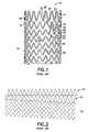
- FIG. 1is a broken side elevation view of a prior art helical stent having a cylindrical end and a transition zone between the helical portion and the cylindrical end and in an expanded state;
- FIG. 2is a broken flattened view of the prior art helical stent of FIG. 1 in an expanded state, wherein the stent has been cut parallel to its longitudinal axis and laid flat;
- FIG. 3is a broken flattened view of a first embodiment of a helical stent according to the invention in an unexpanded state, wherein the stent has been cut parallel to its longitudinal axis and laid flat;
- FIG. 3 ais an enlarged section of a first embodiment of a three-way connection shown in FIG. 3 ;
- FIG. 4is a broken flattened view of a second embodiment of a helical stent according to the invention, wherein the stent has been cut parallel to its longitudinal axis and laid flat;
- FIG. 5is a broken flattened view of a transition zone and a helical portion of a stent according to the invention, wherein the stent has been cut parallel to its longitudinal axis and laid flat.
- the stent 110includes a central helically wound portion 112 (only part of which is shown) defined by hoops 114 and two ends, only one of the ends 116 being shown.
- Each end 116preferably includes a cylindrical or crown portion 118 defined by hoops 120 and a transition zone 122 defined by hoops 124 , the transition zone 122 being located between the cylindrical portion 118 and the helical portion 112 .
- All hoopsare defined by two adjacent struts and a loop-like hinge connecting the struts.
- a hoope.g.
- hoop 114 ais comprised of struts 160 , 162 and hinge 164 , and in the cylindrical portion, a hoop, e.g. hoop 120 a , is comprised of struts 166 , 168 and hinge 170 .
- a hoop, e.g. hoop 124 ais comprised of struts 172 , 174 of different lengths and a connecting hinge 176 .
- the strut length along the helical portionis relatively constant except near the transition zone, where the struts decrease in length, the strut length at the cylindrical portion is relatively constant, and the struts of the transition zone vary in size, generally progressively increasing in length.
- the struts of the helical portion, cylindrical portion and transition zoneall extend in substantially parallel to the longitudinal axis of the stent.
- adjacent strutsare moved apart and angled relative to each other.
- a junction 126is formed where the start of the transition zone 122 joins the end of the transition zone. Junction 126 is located at the end of the longest hoop 129 . In the preferred embodiment, the junction 126 forms the base of a three-way division, or trident 130 , which is located at the “inner” end of the longest hoop 129 at the end of the transition zone 122 (the strut end which is farthest from the cylindrical portion 118 and nearest the helical portion 112 of the stent).
- One outside leg of the trident 130is a strut 128 of the longest hoop 129 of the transition zone 122 ; the other outside leg 132 is the first strut at the beginning of the helical hoops 114 ; and, the middle leg 134 is the longest strut 134 which joins to the short leg 136 at the beginning of the transition zone 122 .
- the flexibility of the hinge (or tab) 138 joining legs 128 and 134is substantially independent of the hinge 140 joining legs 132 and 134 so that the displacement of these legs is substantially decoupled.
- This constructionreduces or eliminates the overly-rigid section in the transition taught by Cottone in the prior art.
- all of the connecting bridges 142 which join adjacent turns of the stentare all in the same basic orientation and the hoops remain “in phase” and the stent can easily expand and collapse.
- junction 126 b defining the “trident”is configured at the “outer” end of the longest hoop 129 ( FIG. 3 ) of the transition zone 122 b .
- the long strut 128 b at the end of the transitionis one outer leg of the trident; the first (short) strut 134 b at the beginning of the transition is a second outer leg of the trident; and the longest strut 132 b that connects the transition zone 122 b to the beginning of the helical portion 112 b of the stent is a middle leg of the trident.
- the tridentis seen to be comprised of two struts of a common hoop at the end of the transition zone, as well as an adjacent strut which is connected to either the beginning of the transition zone or the helical portion.
- the junction of the tridentincludes the hinge of the common hoop, as well as a hinge connecting the adjacent strut to the hinge of the common hoop.
- the transition zone 122has struts 125 of different lengths, and each strut has a width that gives that strut the same opening stiffness as other struts of different lengths.
- the problem of strut stiffness found in the Cottone prior artis ameliorated by not having the full length of a strut contribute to its flexibility. That is, referring to FIG. 5 , the kerf 150 between two adjacent struts 152 , 154 does not necessarily have to go all the way to the end of those struts.
- the kerf 150can be made shorter, resulting in shorter flexible segments to the strut and a non-flexing “tab” 156 at the end of the struts 152 , 154 which is not separated by the kerf 150 .
- Each tab 156has a length substantially greater than a width of the struts to which it is connected.
- the longer strutscan be made less flexible without having to increase their width (or thickness) to accommodate the longer strut length.
- the longer strutscan have substantially the same flexibility and expansion force as the shorter struts of the transition by making all the kerfs approximately the same length.
- the tabs 156will vary in size.
Landscapes
- Health & Medical Sciences (AREA)
- Engineering & Computer Science (AREA)
- Biomedical Technology (AREA)
- Heart & Thoracic Surgery (AREA)
- Optics & Photonics (AREA)
- Cardiology (AREA)
- Oral & Maxillofacial Surgery (AREA)
- Transplantation (AREA)
- Physics & Mathematics (AREA)
- Vascular Medicine (AREA)
- Life Sciences & Earth Sciences (AREA)
- Animal Behavior & Ethology (AREA)
- General Health & Medical Sciences (AREA)
- Public Health (AREA)
- Veterinary Medicine (AREA)
- Media Introduction/Drainage Providing Device (AREA)
Abstract
Description
Claims (22)
Priority Applications (1)
| Application Number | Priority Date | Filing Date | Title |
|---|---|---|---|
| US10/206,489US6969402B2 (en) | 2002-07-26 | 2002-07-26 | Helical stent having flexible transition zone |
Applications Claiming Priority (1)
| Application Number | Priority Date | Filing Date | Title |
|---|---|---|---|
| US10/206,489US6969402B2 (en) | 2002-07-26 | 2002-07-26 | Helical stent having flexible transition zone |
Publications (2)
| Publication Number | Publication Date |
|---|---|
| US20040034402A1 US20040034402A1 (en) | 2004-02-19 |
| US6969402B2true US6969402B2 (en) | 2005-11-29 |
Family
ID=31714209
Family Applications (1)
| Application Number | Title | Priority Date | Filing Date |
|---|---|---|---|
| US10/206,489Expired - Fee RelatedUS6969402B2 (en) | 2002-07-26 | 2002-07-26 | Helical stent having flexible transition zone |
Country Status (1)
| Country | Link |
|---|---|
| US (1) | US6969402B2 (en) |
Cited By (57)
| Publication number | Priority date | Publication date | Assignee | Title |
|---|---|---|---|---|
| US20060060266A1 (en)* | 2004-09-01 | 2006-03-23 | Pst, Llc | Stent and method for manufacturing the stent |
| US20060064154A1 (en)* | 2004-09-01 | 2006-03-23 | Pst, Llc | Stent and method for manufacturing the stent |
| US7217255B2 (en) | 1999-12-30 | 2007-05-15 | Advanced Cardiovascular Systems, Inc. | Embolic protection devices |
| US20070129786A1 (en)* | 2005-10-14 | 2007-06-07 | Bradley Beach | Helical stent |
| US20070129785A1 (en)* | 2005-11-14 | 2007-06-07 | Ev3, Inc. | Stent and stent delivery system for ostial locations in a conduit |
| US7241304B2 (en) | 2001-12-21 | 2007-07-10 | Advanced Cardiovascular Systems, Inc. | Flexible and conformable embolic filtering devices |
| US7244267B2 (en) | 2001-06-29 | 2007-07-17 | Advanced Cardiovascular Systems, Inc. | Filter device for embolic protection systems |
| US7252675B2 (en) | 2002-09-30 | 2007-08-07 | Advanced Cardiovascular, Inc. | Embolic filtering devices |
| US20070233235A1 (en)* | 2002-10-09 | 2007-10-04 | Boston Scientific Scimed, Inc. | Stent with Improved Flexibility |
| US7306619B1 (en) | 2001-08-30 | 2007-12-11 | Advanced Cardiovascular Systems, Inc. | Self furling umbrella frame for carotid filter |
| US7331973B2 (en) | 2002-09-30 | 2008-02-19 | Avdanced Cardiovascular Systems, Inc. | Guide wire with embolic filtering attachment |
| US7338510B2 (en) | 2001-06-29 | 2008-03-04 | Advanced Cardiovascular Systems, Inc. | Variable thickness embolic filtering devices and method of manufacturing the same |
| US7425215B2 (en) | 2000-10-17 | 2008-09-16 | Advanced Cardiovascular Systems, Inc. | Delivery systems for embolic filter devices |
| US20080228261A1 (en)* | 2007-03-13 | 2008-09-18 | Abbott Laboratories | Intravascular stent with integrated link and ring strut |
| US7537598B2 (en) | 2000-07-13 | 2009-05-26 | Advanced Cardiovascular Systems, Inc. | Embolic protection guide wire |
| US7537601B2 (en) | 2000-11-09 | 2009-05-26 | Advanced Cardiovascular Systems, Inc. | Apparatus for capturing objects beyond an operative site utilizing a capture device delivered on a medical guide wire |
| US7572272B2 (en) | 2002-06-26 | 2009-08-11 | Advanced Cardiovascular Systems, Inc. | Embolic filtering devices for bifurcated vessels |
| US7637939B2 (en) | 2005-06-30 | 2009-12-29 | Boston Scientific Scimed, Inc. | Hybrid stent |
| US7662166B2 (en) | 2000-12-19 | 2010-02-16 | Advanced Cardiocascular Systems, Inc. | Sheathless embolic protection system |
| US7678129B1 (en) | 2004-03-19 | 2010-03-16 | Advanced Cardiovascular Systems, Inc. | Locking component for an embolic filter assembly |
| US7678131B2 (en) | 2002-10-31 | 2010-03-16 | Advanced Cardiovascular Systems, Inc. | Single-wire expandable cages for embolic filtering devices |
| US7780694B2 (en) | 1999-12-23 | 2010-08-24 | Advanced Cardiovascular Systems, Inc. | Intravascular device and system |
| US7803180B2 (en) | 2005-04-04 | 2010-09-28 | Flexible Stenting Solutions, Inc. | Flexible stent |
| WO2010132707A1 (en) | 2009-05-14 | 2010-11-18 | Orbusneich Medical, Inc. | Self-expanding stent with polygon transition zone |
| US7842064B2 (en) | 2001-08-31 | 2010-11-30 | Advanced Cardiovascular Systems, Inc. | Hinged short cage for an embolic protection device |
| US7867273B2 (en) | 2007-06-27 | 2011-01-11 | Abbott Laboratories | Endoprostheses for peripheral arteries and other body vessels |
| US7892251B1 (en) | 2003-11-12 | 2011-02-22 | Advanced Cardiovascular Systems, Inc. | Component for delivering and locking a medical device to a guide wire |
| US20110071620A1 (en)* | 2009-09-18 | 2011-03-24 | Medtronic Vascular, Inc. | Methods for Forming an Orthogonal End on a Helical Stent |
| US7918820B2 (en) | 1999-12-30 | 2011-04-05 | Advanced Cardiovascular Systems, Inc. | Device for, and method of, blocking emboli in vessels such as blood arteries |
| US20110166641A1 (en)* | 2007-02-12 | 2011-07-07 | C.R. Bard Inc. | Highly flexible stent and method of manufacture |
| US20110218615A1 (en)* | 2010-03-02 | 2011-09-08 | Medtronic Vascular, Inc. | Stent With Multi-Crown Constraint and Method for Ending Helical Wound Stents |
| US8038707B2 (en) | 2002-08-30 | 2011-10-18 | C.R. Bard, Inc. | Helical stent having improved flexibility and expandability |
| US8137377B2 (en) | 1999-12-23 | 2012-03-20 | Abbott Laboratories | Embolic basket |
| US8142442B2 (en) | 1999-12-23 | 2012-03-27 | Abbott Laboratories | Snare |
| US8206434B2 (en) | 2010-03-02 | 2012-06-26 | Medtronic Vascular, Inc. | Stent with sinusoidal wave form and orthogonal end and method for making same |
| US8216209B2 (en) | 2007-05-31 | 2012-07-10 | Abbott Cardiovascular Systems Inc. | Method and apparatus for delivering an agent to a kidney |
| US8262689B2 (en) | 2001-09-28 | 2012-09-11 | Advanced Cardiovascular Systems, Inc. | Embolic filtering devices |
| US8328072B2 (en) | 2010-07-19 | 2012-12-11 | Medtronic Vascular, Inc. | Method for forming a wave form used to make wound stents |
| US8333799B2 (en) | 2007-02-12 | 2012-12-18 | C. R. Bard, Inc. | Highly flexible stent and method of manufacture |
| US8500794B2 (en) | 2007-08-02 | 2013-08-06 | Flexible Stenting Solutions, Inc. | Flexible stent |
| US8512395B2 (en) | 2010-12-30 | 2013-08-20 | Boston Scientific Scimed, Inc. | Stent with horseshoe shaped bridges |
| US8591540B2 (en) | 2003-02-27 | 2013-11-26 | Abbott Cardiovascular Systems Inc. | Embolic filtering devices |
| US8663313B2 (en) | 2011-03-03 | 2014-03-04 | Boston Scientific Scimed, Inc. | Low strain high strength stent |
| WO2014063650A1 (en)* | 2012-10-26 | 2014-05-01 | Zhejiang Zylox Medical Device Co., Ltd. | Self-expanding stent |
| US8790388B2 (en) | 2011-03-03 | 2014-07-29 | Boston Scientific Scimed, Inc. | Stent with reduced profile |
| US8845583B2 (en) | 1999-12-30 | 2014-09-30 | Abbott Cardiovascular Systems Inc. | Embolic protection devices |
| US8889175B2 (en) | 2010-04-30 | 2014-11-18 | Indian Institute Of Technology Bombay | Nanoparticulate in-situ gels as vitreous humor substitutes for ocular diseases |
| US9149376B2 (en) | 2008-10-06 | 2015-10-06 | Cordis Corporation | Reconstrainable stent delivery system |
| US9238260B2 (en) | 2012-04-18 | 2016-01-19 | Medtronic Vascular, Inc. | Method and apparatus for creating formed elements used to make wound stents |
| US9242290B2 (en) | 2012-04-03 | 2016-01-26 | Medtronic Vascular, Inc. | Method and apparatus for creating formed elements used to make wound stents |
| US9259305B2 (en) | 2005-03-31 | 2016-02-16 | Abbott Cardiovascular Systems Inc. | Guide wire locking mechanism for rapid exchange and other catheter systems |
| US9296034B2 (en) | 2011-07-26 | 2016-03-29 | Medtronic Vascular, Inc. | Apparatus and method for forming a wave form for a stent from a wire |
| CN105496614A (en)* | 2016-01-21 | 2016-04-20 | 浙江巴泰医疗科技有限公司 | Medical self-expanding support |
| US9364351B2 (en) | 2012-04-23 | 2016-06-14 | Medtronic Vascular, Inc. | Method for forming a stent |
| US9456911B2 (en) | 2006-02-14 | 2016-10-04 | Angiomed Gmbh & Co. Medizintechnik | Highly flexible stent and method of manufacture |
| WO2017124375A1 (en)* | 2016-01-21 | 2017-07-27 | 浙江巴泰医疗科技有限公司 | Self-expanding stent for medical use |
| US10433987B2 (en) | 2002-08-30 | 2019-10-08 | C. R. Bard, Inc. | Highly flexible stent and method of manufacture |
Families Citing this family (39)
| Publication number | Priority date | Publication date | Assignee | Title |
|---|---|---|---|---|
| US8353948B2 (en)* | 1997-01-24 | 2013-01-15 | Celonova Stent, Inc. | Fracture-resistant helical stent incorporating bistable cells and methods of use |
| US6799637B2 (en) | 2000-10-20 | 2004-10-05 | Schlumberger Technology Corporation | Expandable tubing and method |
| GB0020491D0 (en) | 2000-08-18 | 2000-10-11 | Angiomed Ag | Stent with attached element and method of making such a stent |
| NO335594B1 (en)* | 2001-01-16 | 2015-01-12 | Halliburton Energy Serv Inc | Expandable devices and methods thereof |
| US20040158314A1 (en)* | 2002-12-24 | 2004-08-12 | Novostent Corporation | Ribbon-type vascular prosthesis having stress-relieving articulation and methods of use |
| US7846198B2 (en)* | 2002-12-24 | 2010-12-07 | Novostent Corporation | Vascular prosthesis and methods of use |
| US20050033410A1 (en)* | 2002-12-24 | 2005-02-10 | Novostent Corporation | Vascular prothesis having flexible configuration |
| US20050165469A1 (en)* | 2002-12-24 | 2005-07-28 | Michael Hogendijk | Vascular prosthesis including torsional stabilizer and methods of use |
| US20040160685A1 (en)* | 2003-01-27 | 2004-08-19 | Everardo Daniel Faires Quiros | Lower rear view mirror (LRVM for short) |
| CN2817768Y (en)* | 2005-05-24 | 2006-09-20 | 微创医疗器械(上海)有限公司 | Tectorium stand and host cage section thereof |
| GB0609841D0 (en) | 2006-05-17 | 2006-06-28 | Angiomed Ag | Bend-capable tubular prosthesis |
| GB0609911D0 (en) | 2006-05-18 | 2006-06-28 | Angiomed Ag | Bend-capable stent prosthesis |
| GB0616999D0 (en)* | 2006-08-29 | 2006-10-04 | Angiomed Ag | Annular mesh |
| EP2063824B1 (en)* | 2006-09-07 | 2020-10-28 | Angiomed GmbH & Co. Medizintechnik KG | Helical implant having different ends |
| US8545545B2 (en)* | 2006-10-18 | 2013-10-01 | Innovational Holdings Llc | Stent with flexible hinges |
| GB0622465D0 (en) | 2006-11-10 | 2006-12-20 | Angiomed Ag | Stent |
| GB0624419D0 (en)* | 2006-12-06 | 2007-01-17 | Angiomed Ag | Stenting ring with marker |
| US8623070B2 (en) | 2007-03-08 | 2014-01-07 | Thomas O. Bales | Tapered helical stent and method for manufacturing the stent |
| GB0706499D0 (en) | 2007-04-03 | 2007-05-09 | Angiomed Ag | Bendable stent |
| US20080319534A1 (en)* | 2007-06-22 | 2008-12-25 | Medtronic Vascular, Inc. | Stent With Improved Mechanical Properties |
| GB0717481D0 (en) | 2007-09-07 | 2007-10-17 | Angiomed Ag | Self-expansible stent with radiopaque markers |
| CN101732114B (en)* | 2008-11-04 | 2014-07-30 | 上海微创医疗器械(集团)有限公司 | Coronary artery stent with medicine carrying grooves |
| KR101810379B1 (en)* | 2009-02-02 | 2017-12-20 | 코디스 코포레이션 | Flexible stent design |
| WO2011082227A1 (en)* | 2009-12-29 | 2011-07-07 | Boston Scientific Scimed, Inc. | High strength low opening pressure stent design |
| DE102010008362A1 (en)* | 2010-02-17 | 2011-08-18 | Transcatheter Technologies GmbH, 93053 | Medical implant which is expandable from a non-expanded state |
| MX2013001444A (en)* | 2010-08-02 | 2013-03-12 | Cordis Corp | Flexible helical stent having different helical regions. |
| CA2807025C (en) | 2010-08-02 | 2017-01-24 | Cordis Corporation | Flexible helical stent having intermediate non-helical region |
| US9028540B2 (en)* | 2011-03-25 | 2015-05-12 | Covidien Lp | Vascular stent with improved vessel wall apposition |
| US20140031917A1 (en)* | 2012-07-25 | 2014-01-30 | Medtronic Vascular, Inc. | Matched End Stiffness Stent and Method of Manufacture |
| US9254205B2 (en) | 2012-09-27 | 2016-02-09 | Covidien Lp | Vascular stent with improved vessel wall apposition |
| JP2016512751A (en)* | 2013-03-14 | 2016-05-09 | パルマズ サイエンティフィック, インコーポレイテッドPalmaz Scientific, Inc. | Integrated medical device, method for manufacturing the same, and method for using the same |
| US9750603B2 (en)* | 2014-01-27 | 2017-09-05 | Medtronic Vascular Galway | Stented prosthetic heart valve with variable stiffness and methods of use |
| AU2015402709B2 (en)* | 2015-07-23 | 2020-11-26 | Optimed Medizinische Instrumente Gmbh | Stent |
| JP2019506251A (en)* | 2016-02-25 | 2019-03-07 | ウェイク・フォレスト・ユニバーシティ・ヘルス・サイエンシーズWake Forest University Health Sciences | Non-migratory stent device and method |
| MX2019003838A (en)* | 2016-10-04 | 2019-06-24 | Shobayashi Yasuhiro | Flexible stent. |
| CN106726039B (en)* | 2017-02-14 | 2018-07-06 | 浙江巴泰医疗科技有限公司 | A kind of open self-expanding stent of spiral |
| JP7037128B2 (en)* | 2017-03-23 | 2022-03-16 | ニプロ株式会社 | Stent |
| CN108371572B (en)* | 2018-02-11 | 2023-12-12 | 浙江巴泰医疗科技有限公司 | Spiral self-expansion bracket |
| CN108670511A (en)* | 2018-06-04 | 2018-10-19 | 浙江巴泰医疗科技有限公司 | A kind of flexible short holder of screw type |
Citations (6)
| Publication number | Priority date | Publication date | Assignee | Title |
|---|---|---|---|---|
| US5913897A (en) | 1993-09-16 | 1999-06-22 | Cordis Corporation | Endoprosthesis having multiple bridging junctions and procedure |
| US6042597A (en) | 1998-10-23 | 2000-03-28 | Scimed Life Systems, Inc. | Helical stent design |
| US6129755A (en) | 1998-01-09 | 2000-10-10 | Nitinol Development Corporation | Intravascular stent having an improved strut configuration |
| US6190406B1 (en) | 1998-01-09 | 2001-02-20 | Nitinal Development Corporation | Intravascular stent having tapered struts |
| WO2001089421A2 (en) | 2000-05-22 | 2001-11-29 | Orbus Medical Technologies Inc. | Self-expanding stent |
| US6342067B1 (en) | 1998-01-09 | 2002-01-29 | Nitinol Development Corporation | Intravascular stent having curved bridges for connecting adjacent hoops |
- 2002
- 2002-07-26USUS10/206,489patent/US6969402B2/ennot_activeExpired - Fee Related
Patent Citations (7)
| Publication number | Priority date | Publication date | Assignee | Title |
|---|---|---|---|---|
| US5913897A (en) | 1993-09-16 | 1999-06-22 | Cordis Corporation | Endoprosthesis having multiple bridging junctions and procedure |
| US6129755A (en) | 1998-01-09 | 2000-10-10 | Nitinol Development Corporation | Intravascular stent having an improved strut configuration |
| US6190406B1 (en) | 1998-01-09 | 2001-02-20 | Nitinal Development Corporation | Intravascular stent having tapered struts |
| US6342067B1 (en) | 1998-01-09 | 2002-01-29 | Nitinol Development Corporation | Intravascular stent having curved bridges for connecting adjacent hoops |
| US6042597A (en) | 1998-10-23 | 2000-03-28 | Scimed Life Systems, Inc. | Helical stent design |
| WO2001089421A2 (en) | 2000-05-22 | 2001-11-29 | Orbus Medical Technologies Inc. | Self-expanding stent |
| US20020116044A1 (en)* | 2000-05-22 | 2002-08-22 | Cottone, Robert John | Self-expanding stent |
Cited By (105)
| Publication number | Priority date | Publication date | Assignee | Title |
|---|---|---|---|---|
| US7780694B2 (en) | 1999-12-23 | 2010-08-24 | Advanced Cardiovascular Systems, Inc. | Intravascular device and system |
| US8137377B2 (en) | 1999-12-23 | 2012-03-20 | Abbott Laboratories | Embolic basket |
| US8142442B2 (en) | 1999-12-23 | 2012-03-27 | Abbott Laboratories | Snare |
| US8845583B2 (en) | 1999-12-30 | 2014-09-30 | Abbott Cardiovascular Systems Inc. | Embolic protection devices |
| US7217255B2 (en) | 1999-12-30 | 2007-05-15 | Advanced Cardiovascular Systems, Inc. | Embolic protection devices |
| US7918820B2 (en) | 1999-12-30 | 2011-04-05 | Advanced Cardiovascular Systems, Inc. | Device for, and method of, blocking emboli in vessels such as blood arteries |
| US8177791B2 (en) | 2000-07-13 | 2012-05-15 | Abbott Cardiovascular Systems Inc. | Embolic protection guide wire |
| US7537598B2 (en) | 2000-07-13 | 2009-05-26 | Advanced Cardiovascular Systems, Inc. | Embolic protection guide wire |
| US7425215B2 (en) | 2000-10-17 | 2008-09-16 | Advanced Cardiovascular Systems, Inc. | Delivery systems for embolic filter devices |
| US7537601B2 (en) | 2000-11-09 | 2009-05-26 | Advanced Cardiovascular Systems, Inc. | Apparatus for capturing objects beyond an operative site utilizing a capture device delivered on a medical guide wire |
| US7931666B2 (en)* | 2000-12-19 | 2011-04-26 | Advanced Cardiovascular Systems, Inc. | Sheathless embolic protection system |
| US7662166B2 (en) | 2000-12-19 | 2010-02-16 | Advanced Cardiocascular Systems, Inc. | Sheathless embolic protection system |
| US7338510B2 (en) | 2001-06-29 | 2008-03-04 | Advanced Cardiovascular Systems, Inc. | Variable thickness embolic filtering devices and method of manufacturing the same |
| US8016854B2 (en) | 2001-06-29 | 2011-09-13 | Abbott Cardiovascular Systems Inc. | Variable thickness embolic filtering devices and methods of manufacturing the same |
| US7244267B2 (en) | 2001-06-29 | 2007-07-17 | Advanced Cardiovascular Systems, Inc. | Filter device for embolic protection systems |
| US7959646B2 (en) | 2001-06-29 | 2011-06-14 | Abbott Cardiovascular Systems Inc. | Filter device for embolic protection systems |
| US7306619B1 (en) | 2001-08-30 | 2007-12-11 | Advanced Cardiovascular Systems, Inc. | Self furling umbrella frame for carotid filter |
| US7959647B2 (en) | 2001-08-30 | 2011-06-14 | Abbott Cardiovascular Systems Inc. | Self furling umbrella frame for carotid filter |
| US7842064B2 (en) | 2001-08-31 | 2010-11-30 | Advanced Cardiovascular Systems, Inc. | Hinged short cage for an embolic protection device |
| US8262689B2 (en) | 2001-09-28 | 2012-09-11 | Advanced Cardiovascular Systems, Inc. | Embolic filtering devices |
| US7972356B2 (en) | 2001-12-21 | 2011-07-05 | Abbott Cardiovascular Systems, Inc. | Flexible and conformable embolic filtering devices |
| US7241304B2 (en) | 2001-12-21 | 2007-07-10 | Advanced Cardiovascular Systems, Inc. | Flexible and conformable embolic filtering devices |
| US7572272B2 (en) | 2002-06-26 | 2009-08-11 | Advanced Cardiovascular Systems, Inc. | Embolic filtering devices for bifurcated vessels |
| US8512391B2 (en) | 2002-08-30 | 2013-08-20 | C. R. Bard, Inc. | Helical stent having struts in a transition zone that progressively increase in length |
| US8038707B2 (en) | 2002-08-30 | 2011-10-18 | C.R. Bard, Inc. | Helical stent having improved flexibility and expandability |
| US9554927B2 (en) | 2002-08-30 | 2017-01-31 | C.R. Bard, Inc. | Helical stent having improved flexibility and expandability |
| US10433987B2 (en) | 2002-08-30 | 2019-10-08 | C. R. Bard, Inc. | Highly flexible stent and method of manufacture |
| US10463509B2 (en) | 2002-08-30 | 2019-11-05 | C. R. Bard, Inc. | Helical stent having improved flexibility and expandability |
| US7252675B2 (en) | 2002-09-30 | 2007-08-07 | Advanced Cardiovascular, Inc. | Embolic filtering devices |
| US7815660B2 (en) | 2002-09-30 | 2010-10-19 | Advanced Cardivascular Systems, Inc. | Guide wire with embolic filtering attachment |
| US8029530B2 (en) | 2002-09-30 | 2011-10-04 | Abbott Cardiovascular Systems Inc. | Guide wire with embolic filtering attachment |
| US7976560B2 (en) | 2002-09-30 | 2011-07-12 | Abbott Cardiovascular Systems Inc. | Embolic filtering devices |
| US7331973B2 (en) | 2002-09-30 | 2008-02-19 | Avdanced Cardiovascular Systems, Inc. | Guide wire with embolic filtering attachment |
| US7842080B2 (en)* | 2002-10-09 | 2010-11-30 | Boston Scientific Scimed, Inc. | Stent with improved flexibility |
| US20070233235A1 (en)* | 2002-10-09 | 2007-10-04 | Boston Scientific Scimed, Inc. | Stent with Improved Flexibility |
| US7678131B2 (en) | 2002-10-31 | 2010-03-16 | Advanced Cardiovascular Systems, Inc. | Single-wire expandable cages for embolic filtering devices |
| US8591540B2 (en) | 2003-02-27 | 2013-11-26 | Abbott Cardiovascular Systems Inc. | Embolic filtering devices |
| US7892251B1 (en) | 2003-11-12 | 2011-02-22 | Advanced Cardiovascular Systems, Inc. | Component for delivering and locking a medical device to a guide wire |
| US7678129B1 (en) | 2004-03-19 | 2010-03-16 | Advanced Cardiovascular Systems, Inc. | Locking component for an embolic filter assembly |
| US7879065B2 (en) | 2004-03-19 | 2011-02-01 | Advanced Cardiovascular Systems, Inc. | Locking component for an embolic filter assembly |
| US8308753B2 (en) | 2004-03-19 | 2012-11-13 | Advanced Cardiovascular Systems, Inc. | Locking component for an embolic filter assembly |
| US7763067B2 (en)* | 2004-09-01 | 2010-07-27 | C. R. Bard, Inc. | Stent and method for manufacturing the stent |
| US20060064155A1 (en)* | 2004-09-01 | 2006-03-23 | Pst, Llc | Stent and method for manufacturing the stent |
| US20060064158A1 (en)* | 2004-09-01 | 2006-03-23 | Pst, Llc | Stent and method for manufacturing the stent |
| US9486339B2 (en) | 2004-09-01 | 2016-11-08 | Angiomed Gmbh & Co. Medizintechnik Kg | Stent and method for manufacturing the stent |
| US10342685B2 (en) | 2004-09-01 | 2019-07-09 | Angiomed Gmbh & Co. Medizintechnik Kg | Stent and method for manufacturing the stent |
| US20060060266A1 (en)* | 2004-09-01 | 2006-03-23 | Pst, Llc | Stent and method for manufacturing the stent |
| US20060064154A1 (en)* | 2004-09-01 | 2006-03-23 | Pst, Llc | Stent and method for manufacturing the stent |
| US7780721B2 (en)* | 2004-09-01 | 2010-08-24 | C. R. Bard, Inc. | Stent and method for manufacturing the stent |
| US10864095B2 (en) | 2004-09-01 | 2020-12-15 | Angiomed Gmbh & Co. Medizintechnik Kg | Stent and method for manufacturing the stent |
| US20060074480A1 (en)* | 2004-09-01 | 2006-04-06 | Pst, Llc | Stent and method for manufacturing the stent |
| US9259305B2 (en) | 2005-03-31 | 2016-02-16 | Abbott Cardiovascular Systems Inc. | Guide wire locking mechanism for rapid exchange and other catheter systems |
| US20140379066A1 (en)* | 2005-04-04 | 2014-12-25 | Flexible Stenting Solutions, Inc. | Flexible stent |
| US20110029064A1 (en)* | 2005-04-04 | 2011-02-03 | Janet Burpee | Flexible stent |
| US9592137B2 (en)* | 2005-04-04 | 2017-03-14 | Flexible Stenting Solutions, Inc. | Flexible stent |
| US7803180B2 (en) | 2005-04-04 | 2010-09-28 | Flexible Stenting Solutions, Inc. | Flexible stent |
| US7637939B2 (en) | 2005-06-30 | 2009-12-29 | Boston Scientific Scimed, Inc. | Hybrid stent |
| US8956400B2 (en)* | 2005-10-14 | 2015-02-17 | Flexible Stenting Solutions, Inc. | Helical stent |
| US20070129786A1 (en)* | 2005-10-14 | 2007-06-07 | Bradley Beach | Helical stent |
| US20070129785A1 (en)* | 2005-11-14 | 2007-06-07 | Ev3, Inc. | Stent and stent delivery system for ostial locations in a conduit |
| US7632302B2 (en) | 2005-11-14 | 2009-12-15 | Ev3 Inc. | Stent and stent delivery system for ostial locations in a conduit |
| US11103371B2 (en) | 2006-02-14 | 2021-08-31 | Angiomed Gmbh & Co. Medizintechnik Kg | Highly flexible stent and method of manufacture |
| US10390978B2 (en) | 2006-02-14 | 2019-08-27 | Angiomed Gmbh & Co. Medizintechnik Kg | Highly flexible stent and method of manufacture |
| US9456911B2 (en) | 2006-02-14 | 2016-10-04 | Angiomed Gmbh & Co. Medizintechnik | Highly flexible stent and method of manufacture |
| US20110166641A1 (en)* | 2007-02-12 | 2011-07-07 | C.R. Bard Inc. | Highly flexible stent and method of manufacture |
| US8328865B2 (en) | 2007-02-12 | 2012-12-11 | C. R. Bard, Inc. | Highly flexible stent and method of manufacture |
| US8333799B2 (en) | 2007-02-12 | 2012-12-18 | C. R. Bard, Inc. | Highly flexible stent and method of manufacture |
| US20080228261A1 (en)* | 2007-03-13 | 2008-09-18 | Abbott Laboratories | Intravascular stent with integrated link and ring strut |
| US8974514B2 (en) | 2007-03-13 | 2015-03-10 | Abbott Cardiovascular Systems Inc. | Intravascular stent with integrated link and ring strut |
| US8216209B2 (en) | 2007-05-31 | 2012-07-10 | Abbott Cardiovascular Systems Inc. | Method and apparatus for delivering an agent to a kidney |
| US7867273B2 (en) | 2007-06-27 | 2011-01-11 | Abbott Laboratories | Endoprostheses for peripheral arteries and other body vessels |
| US8500794B2 (en) | 2007-08-02 | 2013-08-06 | Flexible Stenting Solutions, Inc. | Flexible stent |
| US10010438B2 (en) | 2008-10-06 | 2018-07-03 | Flexible Stenting Solutions, Inc. | Reconstrainable stent delivery system |
| US9149376B2 (en) | 2008-10-06 | 2015-10-06 | Cordis Corporation | Reconstrainable stent delivery system |
| US20110125251A1 (en)* | 2009-05-14 | 2011-05-26 | Orbusneich Medical, Inc. | Self-Expanding Stent with Polygon Transition Zone |
| US9572693B2 (en) | 2009-05-14 | 2017-02-21 | Orbusneich Medical, Inc. | Self-expanding stent with polygon transition zone |
| WO2010132707A1 (en) | 2009-05-14 | 2010-11-18 | Orbusneich Medical, Inc. | Self-expanding stent with polygon transition zone |
| US8366765B2 (en) | 2009-09-18 | 2013-02-05 | Medtronic Vascular, Inc. | Helical stent with connections |
| US20110071619A1 (en)* | 2009-09-18 | 2011-03-24 | Medtronic Vascular, Inc. | Stent With Constant Stiffness Along the Length of the Stent |
| US8226705B2 (en) | 2009-09-18 | 2012-07-24 | Medtronic Vascular, Inc. | Methods for forming an orthogonal end on a helical stent |
| US9060889B2 (en) | 2009-09-18 | 2015-06-23 | Medtronic Vascular, Inc. | Methods for forming an orthogonal end on a helical stent |
| US20110071615A1 (en)* | 2009-09-18 | 2011-03-24 | Medtronic Vascular, Inc. | Methods for Forming an Orthogonal End on a Helical Stent |
| US20110071620A1 (en)* | 2009-09-18 | 2011-03-24 | Medtronic Vascular, Inc. | Methods for Forming an Orthogonal End on a Helical Stent |
| US20110067471A1 (en)* | 2009-09-18 | 2011-03-24 | Medtronic Vascular, Inc. | Method and Apparatus for Creating Formed Elements Used to Make Wound Stents |
| US20110071617A1 (en)* | 2009-09-18 | 2011-03-24 | Medtronic Vascular, Inc. | Stent With Improved Flexibility |
| US8597343B2 (en) | 2009-09-18 | 2013-12-03 | Medtronic Vascular, Inc. | Stent with constant stiffness along the length of the stent |
| US20110071618A1 (en)* | 2009-09-18 | 2011-03-24 | Medtronic Vascular, Inc. | Helical Stent With Connections |
| US9421601B2 (en) | 2009-09-18 | 2016-08-23 | Medtronic Vascular, Inc. | Methods for forming an orthogonal end on a helical stent |
| US8206434B2 (en) | 2010-03-02 | 2012-06-26 | Medtronic Vascular, Inc. | Stent with sinusoidal wave form and orthogonal end and method for making same |
| US20110218615A1 (en)* | 2010-03-02 | 2011-09-08 | Medtronic Vascular, Inc. | Stent With Multi-Crown Constraint and Method for Ending Helical Wound Stents |
| US8889175B2 (en) | 2010-04-30 | 2014-11-18 | Indian Institute Of Technology Bombay | Nanoparticulate in-situ gels as vitreous humor substitutes for ocular diseases |
| US8328072B2 (en) | 2010-07-19 | 2012-12-11 | Medtronic Vascular, Inc. | Method for forming a wave form used to make wound stents |
| US8512395B2 (en) | 2010-12-30 | 2013-08-20 | Boston Scientific Scimed, Inc. | Stent with horseshoe shaped bridges |
| US8663313B2 (en) | 2011-03-03 | 2014-03-04 | Boston Scientific Scimed, Inc. | Low strain high strength stent |
| US8790388B2 (en) | 2011-03-03 | 2014-07-29 | Boston Scientific Scimed, Inc. | Stent with reduced profile |
| US9296034B2 (en) | 2011-07-26 | 2016-03-29 | Medtronic Vascular, Inc. | Apparatus and method for forming a wave form for a stent from a wire |
| US10518315B2 (en) | 2011-07-26 | 2019-12-31 | Medtronic Vascular, Inc. | Apparatus and method for forming a wave form for a stent from a wire |
| US9676022B2 (en) | 2012-04-03 | 2017-06-13 | Medtronic Vascular, Inc. | Apparatus for creating formed elements used to make wound stents |
| US9242290B2 (en) | 2012-04-03 | 2016-01-26 | Medtronic Vascular, Inc. | Method and apparatus for creating formed elements used to make wound stents |
| US9901973B2 (en) | 2012-04-18 | 2018-02-27 | Medtronic Vascular, Inc. | Method and apparatus for creating formed elements used to make wound stents |
| US9238260B2 (en) | 2012-04-18 | 2016-01-19 | Medtronic Vascular, Inc. | Method and apparatus for creating formed elements used to make wound stents |
| US9364351B2 (en) | 2012-04-23 | 2016-06-14 | Medtronic Vascular, Inc. | Method for forming a stent |
| WO2014063650A1 (en)* | 2012-10-26 | 2014-05-01 | Zhejiang Zylox Medical Device Co., Ltd. | Self-expanding stent |
| WO2017124375A1 (en)* | 2016-01-21 | 2017-07-27 | 浙江巴泰医疗科技有限公司 | Self-expanding stent for medical use |
| CN105496614A (en)* | 2016-01-21 | 2016-04-20 | 浙江巴泰医疗科技有限公司 | Medical self-expanding support |
Also Published As
| Publication number | Publication date |
|---|---|
| US20040034402A1 (en) | 2004-02-19 |
Similar Documents
| Publication | Publication Date | Title |
|---|---|---|
| US6969402B2 (en) | Helical stent having flexible transition zone | |
| US10463509B2 (en) | Helical stent having improved flexibility and expandability | |
| US11771573B2 (en) | Side branch stent graft | |
| AU2005282354B2 (en) | Optimized flex link for expandable stent | |
| EP1757249B2 (en) | Helical stent design | |
| US8328864B2 (en) | Stent having phased hoop sections | |
| US7867272B2 (en) | Stent having twist cancellation geometry | |
| US20020055771A1 (en) | Medical prosthesis | |
| US7578840B2 (en) | Stent with reduced profile | |
| EP2427149B1 (en) | A medical device suitable for location in body lumen | |
| US20010032010A1 (en) | Medical prosthesis | |
| US8968386B2 (en) | Stent and method for maintaining the area of a body lumen | |
| JP2009513234A (en) | Stent with untwisted shape | |
| AU2012202185A1 (en) | Stent having phased hoop sections |
Legal Events
| Date | Code | Title | Description |
|---|---|---|---|
| AS | Assignment | Owner name:SYNTHEON, LLC, FLORIDA Free format text:ASSIGNMENT OF ASSIGNORS INTEREST;ASSIGNORS:BALES, THOMAS O.;PERRY, KENNETH E.;REEL/FRAME:013144/0051 Effective date:20020716 | |
| AS | Assignment | Owner name:BOSTON SCIENTIFIC SCIMED, INC., MINNESOTA Free format text:ASSIGNMENT OF ASSIGNORS INTEREST;ASSIGNOR:SYNTHEON, LLC;REEL/FRAME:020762/0467 Effective date:20061130 | |
| FEPP | Fee payment procedure | Free format text:PAT HOLDER NO LONGER CLAIMS SMALL ENTITY STATUS, ENTITY STATUS SET TO UNDISCOUNTED (ORIGINAL EVENT CODE: STOL); ENTITY STATUS OF PATENT OWNER: LARGE ENTITY | |
| REFU | Refund | Free format text:REFUND - SURCHARGE, PETITION TO ACCEPT PYMT AFTER EXP, UNINTENTIONAL (ORIGINAL EVENT CODE: R2551); ENTITY STATUS OF PATENT OWNER: LARGE ENTITY | |
| FPAY | Fee payment | Year of fee payment:4 | |
| FPAY | Fee payment | Year of fee payment:8 | |
| REMI | Maintenance fee reminder mailed | ||
| LAPS | Lapse for failure to pay maintenance fees | Free format text:PATENT EXPIRED FOR FAILURE TO PAY MAINTENANCE FEES (ORIGINAL EVENT CODE: EXP.) | |
| STCH | Information on status: patent discontinuation | Free format text:PATENT EXPIRED DUE TO NONPAYMENT OF MAINTENANCE FEES UNDER 37 CFR 1.362 | |
| FP | Lapsed due to failure to pay maintenance fee | Effective date:20171129 |