US6969022B2 - Seat belt retractor - Google Patents
Seat belt retractorDownload PDFInfo
- Publication number
- US6969022B2 US6969022B2US10/683,704US68370403AUS6969022B2US 6969022 B2US6969022 B2US 6969022B2US 68370403 AUS68370403 AUS 68370403AUS 6969022 B2US6969022 B2US 6969022B2
- Authority
- US
- United States
- Prior art keywords
- spool
- seat belt
- locking
- locking wheel
- belt retractor
- Prior art date
- Legal status (The legal status is an assumption and is not a legal conclusion. Google has not performed a legal analysis and makes no representation as to the accuracy of the status listed.)
- Expired - Lifetime, expires
Links
- 230000000670limiting effectEffects0.000claimsabstractdescription47
- 230000007246mechanismEffects0.000claimsabstractdescription27
- 238000010168coupling processMethods0.000claimsabstractdescription3
- 238000005859coupling reactionMethods0.000claimsabstractdescription3
- 230000000452restraining effectEffects0.000description3
- 230000001133accelerationEffects0.000description2
- 230000008859changeEffects0.000description2
- 230000007423decreaseEffects0.000description2
- 230000000694effectsEffects0.000description2
- 230000009471actionEffects0.000description1
- 238000000418atomic force spectrumMethods0.000description1
- 230000008901benefitEffects0.000description1
- 230000004048modificationEffects0.000description1
- 238000012986modificationMethods0.000description1
Images


Classifications
- B—PERFORMING OPERATIONS; TRANSPORTING
- B60—VEHICLES IN GENERAL
- B60R—VEHICLES, VEHICLE FITTINGS, OR VEHICLE PARTS, NOT OTHERWISE PROVIDED FOR
- B60R22/00—Safety belts or body harnesses in vehicles
- B60R22/34—Belt retractors, e.g. reels
- B60R22/341—Belt retractors, e.g. reels comprising energy-absorbing means
- B60R22/3413—Belt retractors, e.g. reels comprising energy-absorbing means operating between belt reel and retractor frame
- B—PERFORMING OPERATIONS; TRANSPORTING
- B60—VEHICLES IN GENERAL
- B60R—VEHICLES, VEHICLE FITTINGS, OR VEHICLE PARTS, NOT OTHERWISE PROVIDED FOR
- B60R22/00—Safety belts or body harnesses in vehicles
- B60R22/28—Safety belts or body harnesses in vehicles incorporating energy-absorbing devices
- B60R2022/286—Safety belts or body harnesses in vehicles incorporating energy-absorbing devices using deformation of material
- B60R2022/287—Safety belts or body harnesses in vehicles incorporating energy-absorbing devices using deformation of material of torsion rods or tubes
Definitions
- the present inventionrelates to a seat belt retractor and particularly to a seat belt retractor with a load limiting function.
- a seat belt retractorhas a generally cylindrical spool on which seat belt webbing is wound.
- the spoolis rotatably mounted to wind-up or pay out seat belt webbing, depending upon the direction of rotation.
- the spoolis biased in the wind-up direction by a clock spring so that the seat belt maintains a relatively low level force on a vehicle occupant tending to pull him back into the vehicle seat in a comfortable manner, but allowing him to move forward to adjust a car radio and so forth.
- An acceleration sensordetects acceleration or deceleration above a predetermined level, as an indication of a crash, and locks the retractor against the further payout of webbing to securely restrain the vehicle occupant in the vehicle seat.
- Modern seat belt systemsinclude a load limiting function that allows some controlled payout of the belt webbing before locking fully, so as to more gradually decrease the momentum of the vehicle occupant.
- Thisis often achieved using a torsion bar mounted coaxially in the spool.
- the torsion bartwists about its own axis, after the spool mechanism is locked and typically allows up to two turns of the spool. In this way the crash forces felt by the vehicle occupant increase linearly as the crash forces increase, until the torsion bar begins to be twisted.
- the torsion barstops twisting when the load applied from the vehicle occupant diminishes.
- the locking wheelis locked in position by the lockbar, but the spool can turn only when the torsion bar torsion bar is twisted allowing the spool to turn.
- a second stage of operationis provided by a wire element housed in the spool body.
- the wire elementworks in parallel with the torsion bar to create a higher level of load limiting for a predetermined time or distance.
- the present inventioncan provide the advantage of improving the crash force curve further and effectively restraining the vehicle occupant during a second impact.
- a seat belt retractorcomprising: a rotatable spool having a spool body; a primary force limiting mechanism comprising a torsion bar attached at one end to a locking wheel and at the other end to the spool; and a secondary force limiting mechanism releasably coupled in a force path between the spool and the locking wheel and a means for de-coupling the secondary force limiting mechanism after a predetermined amount of twisting of the torsion bar due to a load applied by a vehicle occupant secured by a seat belt webbing that is at least partially wound upon the spool, and wherein a locking means comprises a locking element that is resiliently biased to a position wherein it locks the spool to the locking wheel and is held out of locking engagement by the secondary force limiting mechanism, the locking wheel has a recess therein along which the locking element slides and an abutment at an end of the recess against which the locking element rests.
- the secondary mechanismcomprises a wire releasably connected between the spool and the locking wheel.
- the wireis releasably connected to the spool, preferably between the spool and the locking wheel.
- the wiremay be housed in at least one hole in the spool body and pulled out or extracted from the hole during load limiting. It may be drawn onto the locking wheel.
- the thickness, length and composition of the wireare chosen to suit a vehicle's crash criteria.
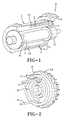
- FIG. 1is a partially cut-away perspective view of the spool and locking assembly of a seat belt retractor according to the present invention.
- FIG. 2is a perspective view of a locking wheel assembly for one end of the seat belt retractor of FIG. 1 .
- FIG. 3is an end view of the locking mechanism shown in FIG. 2 during a first stage of operation labeled as stage one in the graph of FIG. 9 when load limiting is provided by primary and secondary load limiting mechanisms working together.
- FIG. 4is a partially cut-away view of the spool and locking assembly of FIG. 1 from the locking wheel end during a first stage of operation labeled as stage one in the graph of FIG. 9 when load limiting is provided by primary and secondary load limiting mechanisms working together.
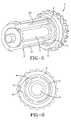
- FIG. 5is a partially cut-away perspective view of the seat belt retractor of FIG. 1 during a second stage of operation labeled as stage two in the graph of FIG. 9 when load limiting is provided only by the primary load limiting mechanism.
- FIG. 6shows the locking wheel end of the seat belt retractor of FIG. 5 during a second stage of operation labeled as stage two in the graph of FIG. 9 when load limiting is provided only by the primary load limiting mechanism.
- FIG. 7is a partially cut-away perspective view of the seat belt retractor of FIG. 1 during a third stage of operation labeled as stage three in the graph of FIG. 9 when a locking mechanism engages the spool and locking wheel and there is no load limiting.
- FIG. 8shows the locking wheel end of the seat belt retractor of FIG. 7 during a third stage of operation labeled as stage three in the graph of FIG. 9 when a locking mechanism engages the spool and locking wheel and there is no load limiting.
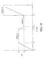
- FIG. 9is a graph of force against time showing various stages of operation of the seat belt retractor.
- FIG. 10is a perspective view of a prior art seat belt retractor that can be adapted to employ the present invention.
- the seat belt retractor of the inventionis of the general form used in a known seat belt retractor as shown in FIG. 10 .
- the remaining figuresshow only the spool and locking assembly part of the seat belt retractor. It will be evident to a skilled person how this part is integrated into a full seat belt retractor.
- Such prior art seat belt retractorsas shown in FIG. 10 , comprise a cylindrical retractor spool 100 mounted for rotation in a frame 108 to wind in and pay out seat belt webbing (not shown).
- a crash a sensorpositioned generally at 130 , but not specifically illustrated, activates a locking mechanism to move a lockbar 110 to engage teeth on a locking ring 103 which is fixed to one end of the spool 100 .
- a rewind spring mechanism 105that comprises a clock type coiled spring that biases the spool 100 to a webbing rewind condition.
- FIG. 1is a partially cut-away perspective view of the spool and locking assembly of a seat belt retractor according to the present invention.
- a hollow spool 1is shown partially cut-away with a locking assembly 2 at one end and a torsion bar 3 arranged along its axis.
- the torsion bar 3is fixed to the spool 1 at the left end as shown in FIG. 1 by splines 21 .
- the torsion baris fixed to the locking assembly 2 at the left end as shown in FIG. 1 by splines 11 fitting in a correspondingly shaped hole in the locking assembly 2 .
- seat belt webbingis wound around the outside of the spool 1 and the spool is supported in a frame for rotation about its longitudinal axis.
- a rewind spring for the spool 1is mounted to the left end, as shown in FIG. 1 .
- a secondary locking meanscomprising a length of load limiting wire 5 having its end portions extending into two holes 10 in the spool body 1 and passing through a locking element 4 and through a locking wheel 6 forming part of the locking assembly 2 .
- FIG. 2is a perspective view of a locking wheel assembly for one end of the seat belt retractor of FIG. 1 .
- the orientation of the wireis shown more clearly in FIG. 2 wherein the wire 5 extends axially through and beyond the locking wheel 6 to be received in the holes 10 in the spool.
- axial and axiallyare understood to refer to orientations of components either along or substantially parallel to the axis of rotation of the spool when the spool is mounted in a retractor frame.
- the wire 5holds the locking element 4 out of engagement with the locking wheel 6 against the action of a spring load.
- a lock bar(not shown) is moved to engage teeth 12 on the locking wheel 6 to lock the spool 1 against rotation, subject to movement due to load limiting arrangements.
- a lock barcan be seen in the prior art retractor shown FIG. 10 and is identified by reference character 110 .
- the wire 5is also being pulled out of the holes 10 in the body of the spool 1 providing an additional secondary load limiting effect during a first stage of operation.
- the combination of the torsion bar 3 and the secondary load limiting wire 5raises the initial load limiting threshold giving a higher combined level of load limiting than the torsion bar alone, i.e. holding the vehicle occupant back in his seat until an airbag is fully deployed to share the restraining load.
- the wire 5has been fully pulled out of the holes 10 in the spool body 1 releasing the locking element 4 to eject into the locking wheel 6 and engage into a recess 7 in the locking wheel 6 .
- the locking wheel 6continues to turn under the influence of the crash forces until the locking element 4 reaches an abutment 8 at the end of the recess 7 .
- the locking element 4connects the spool 1 and the locking wheel 6 together preventing any further load limiting and this constitutes a third stage of operation (identified in the graph in FIG. 9 ).
- the length of the recess 7 and the position of the abutment 8can be varied to modify the crash curve as required by a vehicle manufacturer's specification, by providing a longer or shorter dwell period at the torsion bar only load level (second stage). Ideally the abutment 8 isn't reached in a first impact.
- the seat belt retractorfunctions as a standard retractor without any load limiting function and will restrain the vehicle occupant appropriately for a second impact. This is particularly important because the airbag will usually have deployed in a first impact and thus the seat belt is the only restraint acting on the vehicle occupant.
- FIGS. 3 and 4show the end of the first stage of operations (identified in the graph in FIG. 9 ) wherein the wire 5 has been fully pulled out of the holes 10 in the body of the spool 1 and bent around into a space in the locking wheel 6 .
- the locking element 4is released from the body of the spool 1 and its spring load ejects it into the recess 7 in the locking wheel 6 to connect the spool to the locking wheel 6 and start the second stage of load limiting.
- the spool 1continues to turn under the influence of crash forces as the torsion bar continues to twist and the locking element 4 moves relative to the locking wheel 6 as shown in FIG. 6 by sliding along the recess 7 until it reaches the stop abutment 8 .
- FIG. 9is a digressive load limiting graph showing how a vehicle occupant feels a crash force over a period of time.
- a crashoccurs causing a sudden deceleration or change of direction of the vehicle which is detected by a crash sensor and brings the locking mechanism into effect.
- the crash forces on the vehicle occupantincrease linearly to a force level F 1 .
- the first stage of operationcomes into effect provided by the wire 5 and the torsion bar 3 acting together to provide load limiting and the force levels out at F 1 during the period T 1 to T 2 .
- the wire 5is fully extended and the locking element 4 is released to move relative to the locking wheel 6 .
- the force felt by the vehicle occupantdecreases to a level F 2 provided by the torsion bar 3 alone.
- the torsion barprovides load limiting while the locking element 4 moves around the recess 7 .
- the locking element 4engages the abutment 8 and locks the seat belt retractor fully, preventing further twisting of the torsion bar 3 .
- the seat belt retractoris fully locked and acting as a standard seat belt retractor with no load limiting.
- the vehicle occupantwill feel linearly increasing forces during this third stage. However, by this time the crash forces from the primary impact will usually have dissipated.
- the graphshows the situation for a secondary impact at around time T 4 .
Landscapes
- Engineering & Computer Science (AREA)
- Mechanical Engineering (AREA)
- Automotive Seat Belt Assembly (AREA)
Abstract
Description
Claims (10)
Priority Applications (1)
| Application Number | Priority Date | Filing Date | Title |
|---|---|---|---|
| US10/683,704US6969022B2 (en) | 2003-10-14 | 2003-10-14 | Seat belt retractor |
Applications Claiming Priority (1)
| Application Number | Priority Date | Filing Date | Title |
|---|---|---|---|
| US10/683,704US6969022B2 (en) | 2003-10-14 | 2003-10-14 | Seat belt retractor |
Publications (2)
| Publication Number | Publication Date |
|---|---|
| US20050087641A1 US20050087641A1 (en) | 2005-04-28 |
| US6969022B2true US6969022B2 (en) | 2005-11-29 |
Family
ID=34520561
Family Applications (1)
| Application Number | Title | Priority Date | Filing Date |
|---|---|---|---|
| US10/683,704Expired - LifetimeUS6969022B2 (en) | 2003-10-14 | 2003-10-14 | Seat belt retractor |
Country Status (1)
| Country | Link |
|---|---|
| US (1) | US6969022B2 (en) |
Cited By (29)
| Publication number | Priority date | Publication date | Assignee | Title |
|---|---|---|---|---|
| US20040066027A1 (en)* | 2001-02-06 | 2004-04-08 | Anders Ingemarsson | Safety-belt arrangement |
| US20040113409A1 (en)* | 2001-02-06 | 2004-06-17 | Anders Ingemarsson | Safety-belt arrangement |
| US20050265678A1 (en)* | 2004-05-03 | 2005-12-01 | Manyam Upendra H | Optical fiber for delivering optical energy to or from a work object |
| US20060163410A1 (en)* | 2004-03-31 | 2006-07-27 | Trw Automotive Gmbh | Belt retractor for a vehicle safety belt |
| US20060214494A1 (en)* | 2003-01-31 | 2006-09-28 | Takao Katayama | Seat belt retractor |
| US20060219832A1 (en)* | 2003-01-31 | 2006-10-05 | Takao Katayama | Seat belt retractor |
| US20080306658A1 (en)* | 2004-08-06 | 2008-12-11 | Daimlerchrysler Ag | Motor Vehicle Comprising a Preventive Protective System |
| US20090091115A1 (en)* | 2007-10-03 | 2009-04-09 | Key Safety Systems, Inc. | Seat belt system for adults and children |
| US20110147509A1 (en)* | 2009-12-22 | 2011-06-23 | Bin Wang | Adaptive Load Limiting Retractor |
| US20110303779A1 (en)* | 2010-06-10 | 2011-12-15 | Kabushiki Kaisha Tokai-Rika-Denki-Seisakusho | Webbing take-up device |
| USD655223S1 (en) | 2010-09-15 | 2012-03-06 | Amsafe Commercial Products, Inc. | Buckle assembly |
| USD661619S1 (en) | 2010-09-15 | 2012-06-12 | Amsafe Commercial Products, Inc. | Buckle assembly |
| US8303043B2 (en) | 2008-09-29 | 2012-11-06 | Amsafe, Inc. (Phoenix Group) | Tensioning apparatuses for occupant restraint systems and associated systems and methods |
| US8327513B2 (en) | 2005-06-09 | 2012-12-11 | Amsafe, Inc. | Buckle assembly having single release for multiple belt connectors |
| US8393645B2 (en) | 2009-11-02 | 2013-03-12 | Amsafe Commercial Products, Inc. | Devices for adjusting tension in seat belts and other restraint system webs, and associated methods |
| WO2013073878A1 (en) | 2011-11-16 | 2013-05-23 | Samsung Electronics Co., Ltd. | Method and apparatus for transmitting and receiving signals in multi-antenna communication system |
| US20130140390A1 (en)* | 2011-10-21 | 2013-06-06 | Tk Holdings Inc. | Retractor |
| US8627554B1 (en) | 2010-05-03 | 2014-01-14 | Amsafe, Inc. (Phoenix Group) | Buckle assemblies with swivel and dual release features and associated methods of use and manufacture |
| US8683666B2 (en) | 2009-11-04 | 2014-04-01 | Amsafe Commercial Products, Inc. | Restraint system buckle components having tactile surfaces, and associated methods of use and manufacture |
| US8777323B2 (en) | 2010-07-20 | 2014-07-15 | Amsafe, Inc. | Restraint harnesses and associated methods of use and manufacture |
| US8820789B2 (en) | 2009-02-23 | 2014-09-02 | Amsafe, Inc. | Seat harness pretensioner |
| US9022483B2 (en) | 2012-06-07 | 2015-05-05 | Shield Restraint Systems, Inc. | Seatbelt buckle tongue assembly |
| US9119445B2 (en) | 2013-02-19 | 2015-09-01 | Amsafe, Inc. | Buckle assemblies with lift latches and associated methods and systems |
| US9277788B2 (en) | 2013-02-19 | 2016-03-08 | Amsafe, Inc. | Dual release buckle assemblies and associated systems and methods |
| US9775410B2 (en) | 2014-12-16 | 2017-10-03 | Shield Restraint Systems, Inc. | Web adjusters for use with restraint systems and associated methods of use and manufacture |
| US9814282B2 (en) | 2016-02-02 | 2017-11-14 | Shield Restraint Systems, Inc. | Harsh environment buckle assemblies and associated systems and methods |
| US10604259B2 (en) | 2016-01-20 | 2020-03-31 | Amsafe, Inc. | Occupant restraint systems having extending restraints, and associated systems and methods |
| US10611334B2 (en) | 2017-02-07 | 2020-04-07 | Shield Restraint Systems, Inc. | Web adjuster |
| US20230271588A1 (en)* | 2022-02-28 | 2023-08-31 | Ford Global Technologies, Llc | Load limiting seatbelt retractor |
Families Citing this family (10)
| Publication number | Priority date | Publication date | Assignee | Title |
|---|---|---|---|---|
| CN100369329C (en)* | 2003-03-31 | 2008-02-13 | 住友电气工业株式会社 | Anisotropic conductive film and manufacturing method thereof |
| DE602004009303T2 (en)* | 2004-07-20 | 2008-07-10 | Key Safety Systems, Inc., Sterling Heights | retractor |
| DE102005032012A1 (en)* | 2005-07-01 | 2007-01-11 | Takata-Petri (Ulm) Gmbh | retractor |
| JP5078110B2 (en)* | 2006-06-15 | 2012-11-21 | タカタ株式会社 | Seat belt retractor and seat belt device provided with the same |
| JP6126986B2 (en)* | 2013-12-24 | 2017-05-10 | 株式会社東海理化電機製作所 | Webbing take-up device |
| JP6126985B2 (en)* | 2013-12-24 | 2017-05-10 | 株式会社東海理化電機製作所 | Webbing take-up device |
| CN111281254B (en)* | 2020-03-27 | 2025-01-14 | 厦门瑞尔特卫浴科技股份有限公司 | A wire taking-up mechanism and bathroom equipment having the same |
| CN113183914B (en)* | 2021-04-06 | 2022-04-01 | 重庆光大产业有限公司 | Reliable coiler is steady and just terminates to limit for force |
| TWI837736B (en)* | 2021-08-13 | 2024-04-01 | 宏霖工業股份有限公司 | Reel Assembly |
| USD1062408S1 (en)* | 2022-09-15 | 2025-02-18 | Chin-Sung Huang | Ratchet gear for a seat belt adjuster |
Citations (5)
| Publication number | Priority date | Publication date | Assignee | Title |
|---|---|---|---|---|
| US6131843A (en) | 1995-08-01 | 2000-10-17 | Autoliv Development Ab | Safety-belt retractor mechanism |
| EP1180457A2 (en) | 2000-08-15 | 2002-02-20 | Kabushiki Kaisha Tokai-Rika-Denki-Seisakusho | Webbing retractor |
| US20020050542A1 (en) | 2000-10-26 | 2002-05-02 | Tomonori Nagata | Webbing retractor |
| US6669133B2 (en) | 2002-04-16 | 2003-12-30 | Breed Automotive Technology, Inc. | Seat belt retractor with multi-level load limiting |
| US6698678B2 (en) | 2001-07-11 | 2004-03-02 | Kabushiki Kaisha Tokai-Rika-Denki-Seisakusho | Webbing retractor and method of retracting webbing |
- 2003
- 2003-10-14USUS10/683,704patent/US6969022B2/ennot_activeExpired - Lifetime
Patent Citations (6)
| Publication number | Priority date | Publication date | Assignee | Title |
|---|---|---|---|---|
| US6131843A (en) | 1995-08-01 | 2000-10-17 | Autoliv Development Ab | Safety-belt retractor mechanism |
| EP1180457A2 (en) | 2000-08-15 | 2002-02-20 | Kabushiki Kaisha Tokai-Rika-Denki-Seisakusho | Webbing retractor |
| US20020050542A1 (en) | 2000-10-26 | 2002-05-02 | Tomonori Nagata | Webbing retractor |
| US6598822B2 (en) | 2000-10-26 | 2003-07-29 | Kabushiki Kaisha Tokai-Rika-Denki-Seisakusho | Webbing retractor |
| US6698678B2 (en) | 2001-07-11 | 2004-03-02 | Kabushiki Kaisha Tokai-Rika-Denki-Seisakusho | Webbing retractor and method of retracting webbing |
| US6669133B2 (en) | 2002-04-16 | 2003-12-30 | Breed Automotive Technology, Inc. | Seat belt retractor with multi-level load limiting |
Cited By (42)
| Publication number | Priority date | Publication date | Assignee | Title |
|---|---|---|---|---|
| US7128343B2 (en)* | 2001-02-06 | 2006-10-31 | Autoliv Asp,Inc. | Safety-belt arrangement |
| US20040113409A1 (en)* | 2001-02-06 | 2004-06-17 | Anders Ingemarsson | Safety-belt arrangement |
| US20040066027A1 (en)* | 2001-02-06 | 2004-04-08 | Anders Ingemarsson | Safety-belt arrangement |
| US7140641B2 (en) | 2001-02-06 | 2006-11-28 | Autoliv Development Ab | Safety-belt arrangement |
| US7753305B2 (en)* | 2003-01-31 | 2010-07-13 | Ashimori Industry Co., Ltd. | Seat belt retractor |
| US20060219832A1 (en)* | 2003-01-31 | 2006-10-05 | Takao Katayama | Seat belt retractor |
| US20060214494A1 (en)* | 2003-01-31 | 2006-09-28 | Takao Katayama | Seat belt retractor |
| US20060163410A1 (en)* | 2004-03-31 | 2006-07-27 | Trw Automotive Gmbh | Belt retractor for a vehicle safety belt |
| US7963474B2 (en)* | 2004-03-31 | 2011-06-21 | Trw Automotive Gmbh | Belt retractor for a vehicle safety belt |
| US7317857B2 (en)* | 2004-05-03 | 2008-01-08 | Nufem | Optical fiber for delivering optical energy to or from a work object |
| US20050265678A1 (en)* | 2004-05-03 | 2005-12-01 | Manyam Upendra H | Optical fiber for delivering optical energy to or from a work object |
| US20080306658A1 (en)* | 2004-08-06 | 2008-12-11 | Daimlerchrysler Ag | Motor Vehicle Comprising a Preventive Protective System |
| US7912609B2 (en)* | 2004-08-06 | 2011-03-22 | Daimler Ag | Motor vehicle comprising a preventive protective system |
| US8567022B2 (en) | 2005-06-09 | 2013-10-29 | Amsafe, Inc. | Buckle assembly having single release for multiple belt connectors |
| US8327513B2 (en) | 2005-06-09 | 2012-12-11 | Amsafe, Inc. | Buckle assembly having single release for multiple belt connectors |
| US20090091115A1 (en)* | 2007-10-03 | 2009-04-09 | Key Safety Systems, Inc. | Seat belt system for adults and children |
| US7571934B2 (en) | 2007-10-03 | 2009-08-11 | Key Safety Systems, Inc. | Seat belt system for adults and children |
| US8303043B2 (en) | 2008-09-29 | 2012-11-06 | Amsafe, Inc. (Phoenix Group) | Tensioning apparatuses for occupant restraint systems and associated systems and methods |
| US8632131B2 (en) | 2008-09-29 | 2014-01-21 | Amsafe, Inc. | Tensioning apparatuses for occupant restraint systems and associated systems and methods |
| US8820789B2 (en) | 2009-02-23 | 2014-09-02 | Amsafe, Inc. | Seat harness pretensioner |
| US8393645B2 (en) | 2009-11-02 | 2013-03-12 | Amsafe Commercial Products, Inc. | Devices for adjusting tension in seat belts and other restraint system webs, and associated methods |
| US8683666B2 (en) | 2009-11-04 | 2014-04-01 | Amsafe Commercial Products, Inc. | Restraint system buckle components having tactile surfaces, and associated methods of use and manufacture |
| US8220735B2 (en)* | 2009-12-22 | 2012-07-17 | Autoliv Asp, Inc. | Adaptive load limiting retractor |
| US20110147509A1 (en)* | 2009-12-22 | 2011-06-23 | Bin Wang | Adaptive Load Limiting Retractor |
| US8627554B1 (en) | 2010-05-03 | 2014-01-14 | Amsafe, Inc. (Phoenix Group) | Buckle assemblies with swivel and dual release features and associated methods of use and manufacture |
| US20110303779A1 (en)* | 2010-06-10 | 2011-12-15 | Kabushiki Kaisha Tokai-Rika-Denki-Seisakusho | Webbing take-up device |
| US8540179B2 (en)* | 2010-06-10 | 2013-09-24 | Kabushiki Kaisha Tokai-Rika-Denki-Seisakusho | Webbing take-up device |
| US8777323B2 (en) | 2010-07-20 | 2014-07-15 | Amsafe, Inc. | Restraint harnesses and associated methods of use and manufacture |
| USD655223S1 (en) | 2010-09-15 | 2012-03-06 | Amsafe Commercial Products, Inc. | Buckle assembly |
| USD661619S1 (en) | 2010-09-15 | 2012-06-12 | Amsafe Commercial Products, Inc. | Buckle assembly |
| US20130140390A1 (en)* | 2011-10-21 | 2013-06-06 | Tk Holdings Inc. | Retractor |
| US10046062B2 (en)* | 2011-10-21 | 2018-08-14 | Joyson Safety Systems Acquisition Llc | Retractor |
| WO2013073878A1 (en) | 2011-11-16 | 2013-05-23 | Samsung Electronics Co., Ltd. | Method and apparatus for transmitting and receiving signals in multi-antenna communication system |
| US9022483B2 (en) | 2012-06-07 | 2015-05-05 | Shield Restraint Systems, Inc. | Seatbelt buckle tongue assembly |
| US9119445B2 (en) | 2013-02-19 | 2015-09-01 | Amsafe, Inc. | Buckle assemblies with lift latches and associated methods and systems |
| US9277788B2 (en) | 2013-02-19 | 2016-03-08 | Amsafe, Inc. | Dual release buckle assemblies and associated systems and methods |
| US9775410B2 (en) | 2014-12-16 | 2017-10-03 | Shield Restraint Systems, Inc. | Web adjusters for use with restraint systems and associated methods of use and manufacture |
| US10604259B2 (en) | 2016-01-20 | 2020-03-31 | Amsafe, Inc. | Occupant restraint systems having extending restraints, and associated systems and methods |
| US9814282B2 (en) | 2016-02-02 | 2017-11-14 | Shield Restraint Systems, Inc. | Harsh environment buckle assemblies and associated systems and methods |
| US10611334B2 (en) | 2017-02-07 | 2020-04-07 | Shield Restraint Systems, Inc. | Web adjuster |
| US20230271588A1 (en)* | 2022-02-28 | 2023-08-31 | Ford Global Technologies, Llc | Load limiting seatbelt retractor |
| US11970131B2 (en)* | 2022-02-28 | 2024-04-30 | Ford Global Technologies, Llc | Load limiting seatbelt retractor |
Also Published As
| Publication number | Publication date |
|---|---|
| US20050087641A1 (en) | 2005-04-28 |
Similar Documents
| Publication | Publication Date | Title |
|---|---|---|
| US6969022B2 (en) | Seat belt retractor | |
| US7025297B2 (en) | Seat belt retractor | |
| US6669133B2 (en) | Seat belt retractor with multi-level load limiting | |
| JP4990770B2 (en) | Seat belt retractor to limit load | |
| WO2004033249A2 (en) | Seat belt retractor | |
| US20070145175A1 (en) | Safety belt roll-up mechanism having a force limitation device actuatable as a function of the length of belt strap withdrawn | |
| EP1619091B1 (en) | Retractor | |
| US3961761A (en) | Storage device for a safety belt | |
| KR100699653B1 (en) | Seat belt retractor | |
| EP1494896B1 (en) | Seat belt retractor | |
| US20020038834A1 (en) | Seatbelt retractor | |
| JP2007153325A (en) | Seat belt retractor including energy absorbing device | |
| US8231073B2 (en) | Load limiting seat belt retractor | |
| US6889930B2 (en) | Seatbelt retractor of an automobile | |
| JP2006205821A (en) | Webbing winding device | |
| JP2019166901A (en) | Seat belt device | |
| GB2376664A (en) | Spool for a vehicle safety restraint |
Legal Events
| Date | Code | Title | Description |
|---|---|---|---|
| AS | Assignment | Owner name:BREED AUTOMOTIVE TECHNOLOGY, INC., FLORIDA Free format text:ASSIGNMENT OF ASSIGNORS INTEREST;ASSIGNORS:BELL, JOHN;JACK, BRIAN;PALLISER, MARTYN;AND OTHERS;REEL/FRAME:015199/0441;SIGNING DATES FROM 20040122 TO 20040125 | |
| AS | Assignment | Owner name:KEY SAFETY SYSTEMS, INC., MICHIGAN Free format text:ASSIGNMENT OF ASSIGNORS INTEREST;ASSIGNOR:BREED AUTOMOTIVE TECHNOLOGY INC.;REEL/FRAME:015219/0274 Effective date:20040412 | |
| STCF | Information on status: patent grant | Free format text:PATENTED CASE | |
| AS | Assignment | Owner name:CITICORP USA, INC., NEW YORK Free format text:SECURITY AGREEMENT;ASSIGNORS:KEY SAFETY SYSTEMS, INC;KSS HOLDINGS, INC;KSS ACQUISITION COMPANY;AND OTHERS;REEL/FRAME:019297/0249 Effective date:20070308 Owner name:CITICORP USA, INC.,NEW YORK Free format text:SECURITY AGREEMENT;ASSIGNORS:KEY SAFETY SYSTEMS, INC;KSS HOLDINGS, INC;KSS ACQUISITION COMPANY;AND OTHERS;REEL/FRAME:019297/0249 Effective date:20070308 | |
| FPAY | Fee payment | Year of fee payment:4 | |
| AS | Assignment | Owner name:UBS AG, STAMFORD BRANCH, CONNECTICUT Free format text:ASSIGNMENT AND ASSUMPTION OF SECURITY INTEREST IN PATENTS;ASSIGNOR:CITICORP USA, INC.;REEL/FRAME:029565/0125 Effective date:20121231 | |
| FPAY | Fee payment | Year of fee payment:8 | |
| AS | Assignment | Owner name:KEY SAFETY SYSTEMS, INC., MICHIGAN Free format text:RELEASE OF SECURITY INTEREST;ASSIGNOR:UBS AG, STAMFORD BRANCH;REEL/FRAME:031327/0676 Effective date:20130717 | |
| AS | Assignment | Owner name:KEY CAYMAN GP LLC, MICHIGAN Free format text:CORRECTIVE ASSIGNMENT TO CORRECT THE NATURE OF CONVEYANCE TO RELEASE OF SECOND LIEN INTEREST IN PATENT COLLATERAL AND THE RECEIVING PARTY NAMES PREVIOUSLY RECORDED ON REEL 031327 FRAME 676. ASSIGNOR(S) HEREBY CONFIRMS THE RELEASE OF SECOND LIEN INTEREST IN PATENT COLLATERAL. SEE ALSO THE ATTACHED DECLARATION;ASSIGNOR:UBS AG, STAMFORD BRANCH;REEL/FRAME:033521/0223 Effective date:20130717 Owner name:KEY SAFETY SYSTEMS OF TEXAS, INC., MICHIGAN Free format text:CORRECTIVE ASSIGNMENT TO CORRECT THE NATURE OF CONVEYANCE TO RELEASE OF SECOND LIEN INTEREST IN PATENT COLLATERAL AND THE RECEIVING PARTY NAMES PREVIOUSLY RECORDED ON REEL 031327 FRAME 676. ASSIGNOR(S) HEREBY CONFIRMS THE RELEASE OF SECOND LIEN INTEREST IN PATENT COLLATERAL. SEE ALSO THE ATTACHED DECLARATION;ASSIGNOR:UBS AG, STAMFORD BRANCH;REEL/FRAME:033521/0223 Effective date:20130717 Owner name:KSS ACQUISITION COMPANY, MICHIGAN Free format text:CORRECTIVE ASSIGNMENT TO CORRECT THE NATURE OF CONVEYANCE TO RELEASE OF SECOND LIEN INTEREST IN PATENT COLLATERAL AND THE RECEIVING PARTY NAMES PREVIOUSLY RECORDED ON REEL 031327 FRAME 676. ASSIGNOR(S) HEREBY CONFIRMS THE RELEASE OF SECOND LIEN INTEREST IN PATENT COLLATERAL. SEE ALSO THE ATTACHED DECLARATION;ASSIGNOR:UBS AG, STAMFORD BRANCH;REEL/FRAME:033521/0223 Effective date:20130717 Owner name:KSS HOLDINGS, INC., MICHIGAN Free format text:CORRECTIVE ASSIGNMENT TO CORRECT THE NATURE OF CONVEYANCE TO RELEASE OF SECOND LIEN INTEREST IN PATENT COLLATERAL AND THE RECEIVING PARTY NAMES PREVIOUSLY RECORDED ON REEL 031327 FRAME 676. ASSIGNOR(S) HEREBY CONFIRMS THE RELEASE OF SECOND LIEN INTEREST IN PATENT COLLATERAL. SEE ALSO THE ATTACHED DECLARATION;ASSIGNOR:UBS AG, STAMFORD BRANCH;REEL/FRAME:033521/0223 Effective date:20130717 Owner name:KEY ELECTRONICS OF NEVADA, INC., MICHIGAN Free format text:CORRECTIVE ASSIGNMENT TO CORRECT THE NATURE OF CONVEYANCE TO RELEASE OF SECOND LIEN INTEREST IN PATENT COLLATERAL AND THE RECEIVING PARTY NAMES PREVIOUSLY RECORDED ON REEL 031327 FRAME 676. ASSIGNOR(S) HEREBY CONFIRMS THE RELEASE OF SECOND LIEN INTEREST IN PATENT COLLATERAL. SEE ALSO THE ATTACHED DECLARATION;ASSIGNOR:UBS AG, STAMFORD BRANCH;REEL/FRAME:033521/0223 Effective date:20130717 Owner name:KEY SAFETY SYSTEMS, INC., MICHIGAN Free format text:CORRECTIVE ASSIGNMENT TO CORRECT THE NATURE OF CONVEYANCE TO RELEASE OF SECOND LIEN INTEREST IN PATENT COLLATERAL AND THE RECEIVING PARTY NAMES PREVIOUSLY RECORDED ON REEL 031327 FRAME 676. ASSIGNOR(S) HEREBY CONFIRMS THE RELEASE OF SECOND LIEN INTEREST IN PATENT COLLATERAL. SEE ALSO THE ATTACHED DECLARATION;ASSIGNOR:UBS AG, STAMFORD BRANCH;REEL/FRAME:033521/0223 Effective date:20130717 Owner name:KEY ASIAN HOLDINGS, INC., MICHIGAN Free format text:CORRECTIVE ASSIGNMENT TO CORRECT THE NATURE OF CONVEYANCE TO RELEASE OF SECOND LIEN INTEREST IN PATENT COLLATERAL AND THE RECEIVING PARTY NAMES PREVIOUSLY RECORDED ON REEL 031327 FRAME 676. ASSIGNOR(S) HEREBY CONFIRMS THE RELEASE OF SECOND LIEN INTEREST IN PATENT COLLATERAL. SEE ALSO THE ATTACHED DECLARATION;ASSIGNOR:UBS AG, STAMFORD BRANCH;REEL/FRAME:033521/0223 Effective date:20130717 Owner name:KEY SAFETY RESTRAINT SYSTEMS, INC., MICHIGAN Free format text:CORRECTIVE ASSIGNMENT TO CORRECT THE NATURE OF CONVEYANCE TO RELEASE OF SECOND LIEN INTEREST IN PATENT COLLATERAL AND THE RECEIVING PARTY NAMES PREVIOUSLY RECORDED ON REEL 031327 FRAME 676. ASSIGNOR(S) HEREBY CONFIRMS THE RELEASE OF SECOND LIEN INTEREST IN PATENT COLLATERAL. SEE ALSO THE ATTACHED DECLARATION;ASSIGNOR:UBS AG, STAMFORD BRANCH;REEL/FRAME:033521/0223 Effective date:20130717 Owner name:HAMLIN INCORPORATED, MICHIGAN Free format text:CORRECTIVE ASSIGNMENT TO CORRECT THE NATURE OF CONVEYANCE TO RELEASE OF SECOND LIEN INTEREST IN PATENT COLLATERAL AND THE RECEIVING PARTY NAMES PREVIOUSLY RECORDED ON REEL 031327 FRAME 676. ASSIGNOR(S) HEREBY CONFIRMS THE RELEASE OF SECOND LIEN INTEREST IN PATENT COLLATERAL. SEE ALSO THE ATTACHED DECLARATION;ASSIGNOR:UBS AG, STAMFORD BRANCH;REEL/FRAME:033521/0223 Effective date:20130717 Owner name:KEY SAFETY SYSTEMS FOREIGN HOLDCO, LLC, MICHIGAN Free format text:CORRECTIVE ASSIGNMENT TO CORRECT THE NATURE OF CONVEYANCE TO RELEASE OF SECOND LIEN INTEREST IN PATENT COLLATERAL AND THE RECEIVING PARTY NAMES PREVIOUSLY RECORDED ON REEL 031327 FRAME 676. ASSIGNOR(S) HEREBY CONFIRMS THE RELEASE OF SECOND LIEN INTEREST IN PATENT COLLATERAL. SEE ALSO THE ATTACHED DECLARATION;ASSIGNOR:UBS AG, STAMFORD BRANCH;REEL/FRAME:033521/0223 Effective date:20130717 Owner name:KEY AUTOMOTIVE, LP, MICHIGAN Free format text:CORRECTIVE ASSIGNMENT TO CORRECT THE NATURE OF CONVEYANCE TO RELEASE OF SECOND LIEN INTEREST IN PATENT COLLATERAL AND THE RECEIVING PARTY NAMES PREVIOUSLY RECORDED ON REEL 031327 FRAME 676. ASSIGNOR(S) HEREBY CONFIRMS THE RELEASE OF SECOND LIEN INTEREST IN PATENT COLLATERAL. SEE ALSO THE ATTACHED DECLARATION;ASSIGNOR:UBS AG, STAMFORD BRANCH;REEL/FRAME:033521/0223 Effective date:20130717 Owner name:KEY INTERNATIONAL MANUFACTURING DEVELOPMENT CORPOR Free format text:CORRECTIVE ASSIGNMENT TO CORRECT THE NATURE OF CONVEYANCE TO RELEASE OF SECOND LIEN INTEREST IN PATENT COLLATERAL AND THE RECEIVING PARTY NAMES PREVIOUSLY RECORDED ON REEL 031327 FRAME 676. ASSIGNOR(S) HEREBY CONFIRMS THE RELEASE OF SECOND LIEN INTEREST IN PATENT COLLATERAL. SEE ALSO THE ATTACHED DECLARATION;ASSIGNOR:UBS AG, STAMFORD BRANCH;REEL/FRAME:033521/0223 Effective date:20130717 Owner name:BREED AUTOMOTIVE TECHNOLOGY, INC., MICHIGAN Free format text:CORRECTIVE ASSIGNMENT TO CORRECT THE NATURE OF CONVEYANCE TO RELEASE OF SECOND LIEN INTEREST IN PATENT COLLATERAL AND THE RECEIVING PARTY NAMES PREVIOUSLY RECORDED ON REEL 031327 FRAME 676. ASSIGNOR(S) HEREBY CONFIRMS THE RELEASE OF SECOND LIEN INTEREST IN PATENT COLLATERAL. SEE ALSO THE ATTACHED DECLARATION;ASSIGNOR:UBS AG, STAMFORD BRANCH;REEL/FRAME:033521/0223 Effective date:20130717 Owner name:KEY AUTOMOTIVE ACCESSORIES, INC., MICHIGAN Free format text:CORRECTIVE ASSIGNMENT TO CORRECT THE NATURE OF CONVEYANCE TO RELEASE OF SECOND LIEN INTEREST IN PATENT COLLATERAL AND THE RECEIVING PARTY NAMES PREVIOUSLY RECORDED ON REEL 031327 FRAME 676. ASSIGNOR(S) HEREBY CONFIRMS THE RELEASE OF SECOND LIEN INTEREST IN PATENT COLLATERAL. SEE ALSO THE ATTACHED DECLARATION;ASSIGNOR:UBS AG, STAMFORD BRANCH;REEL/FRAME:033521/0223 Effective date:20130717 | |
| AS | Assignment | Owner name:KEY AUTOMOTIVE ACCESSORIES, INC., MICHIGAN Free format text:RELEASE OF INTEREST IN PATENT COLLATERAL;ASSIGNOR:UBS AG, STAMFORD BRANCH;REEL/FRAME:033666/0605 Effective date:20140829 Owner name:BREED AUTOMOTIVE TECHNOLOGY, INC., MICHIGAN Free format text:RELEASE OF INTEREST IN PATENT COLLATERAL;ASSIGNOR:UBS AG, STAMFORD BRANCH;REEL/FRAME:033666/0605 Effective date:20140829 Owner name:KEY AUTOMOTIVE, LP, MICHIGAN Free format text:RELEASE OF INTEREST IN PATENT COLLATERAL;ASSIGNOR:UBS AG, STAMFORD BRANCH;REEL/FRAME:033666/0605 Effective date:20140829 Owner name:KSS ACQUISITION COMPANY, MICHIGAN Free format text:RELEASE OF INTEREST IN PATENT COLLATERAL;ASSIGNOR:UBS AG, STAMFORD BRANCH;REEL/FRAME:033666/0605 Effective date:20140829 Owner name:KEY SAFETY SYSTEMS FOREIGN HOLDCO, LLC, MICHIGAN Free format text:RELEASE OF INTEREST IN PATENT COLLATERAL;ASSIGNOR:UBS AG, STAMFORD BRANCH;REEL/FRAME:033666/0605 Effective date:20140829 Owner name:KEY AUTOMOTIVE WEST, INC., MICHIGAN Free format text:RELEASE OF INTEREST IN PATENT COLLATERAL;ASSIGNOR:UBS AG, STAMFORD BRANCH;REEL/FRAME:033666/0605 Effective date:20140829 Owner name:KEY SAFETY SYSTEMS, INC., MICHIGAN Free format text:RELEASE OF INTEREST IN PATENT COLLATERAL;ASSIGNOR:UBS AG, STAMFORD BRANCH;REEL/FRAME:033666/0605 Effective date:20140829 Owner name:KEY ELECTRONICS OF NEVADA, INC., MICHIGAN Free format text:RELEASE OF INTEREST IN PATENT COLLATERAL;ASSIGNOR:UBS AG, STAMFORD BRANCH;REEL/FRAME:033666/0605 Effective date:20140829 Owner name:HAMLIN INCORPORATED, MICHIGAN Free format text:RELEASE OF INTEREST IN PATENT COLLATERAL;ASSIGNOR:UBS AG, STAMFORD BRANCH;REEL/FRAME:033666/0605 Effective date:20140829 Owner name:KEY INTERNATIONAL MANUFACTURING DEVELOPMENT CORPOR Free format text:RELEASE OF INTEREST IN PATENT COLLATERAL;ASSIGNOR:UBS AG, STAMFORD BRANCH;REEL/FRAME:033666/0605 Effective date:20140829 Owner name:KSS HOLDINGS, INC., MICHIGAN Free format text:RELEASE OF INTEREST IN PATENT COLLATERAL;ASSIGNOR:UBS AG, STAMFORD BRANCH;REEL/FRAME:033666/0605 Effective date:20140829 Owner name:KEY SAFETY RESTRAINT SYSTEMS, INC., MICHIGAN Free format text:RELEASE OF INTEREST IN PATENT COLLATERAL;ASSIGNOR:UBS AG, STAMFORD BRANCH;REEL/FRAME:033666/0605 Effective date:20140829 Owner name:KEY SAFETY SYSTEMS OF TEXAS, INC., MICHIGAN Free format text:RELEASE OF INTEREST IN PATENT COLLATERAL;ASSIGNOR:UBS AG, STAMFORD BRANCH;REEL/FRAME:033666/0605 Effective date:20140829 Owner name:KEY CAYMAN GP LLC, MICHIGAN Free format text:RELEASE OF INTEREST IN PATENT COLLATERAL;ASSIGNOR:UBS AG, STAMFORD BRANCH;REEL/FRAME:033666/0605 Effective date:20140829 Owner name:KEY ASIAN HOLDINGS, INC., MICHIGAN Free format text:RELEASE OF INTEREST IN PATENT COLLATERAL;ASSIGNOR:UBS AG, STAMFORD BRANCH;REEL/FRAME:033666/0605 Effective date:20140829 Owner name:UBS AG, STAMFORD BRANCH, CONNECTICUT Free format text:PATENT SECURITY AGREEMENT;ASSIGNOR:KEY SAFETY SYSTEMS, INC.;REEL/FRAME:033673/0524 Effective date:20140829 | |
| FPAY | Fee payment | Year of fee payment:12 | |
| AS | Assignment | Owner name:DEUTSCHE BANK TRUST COMPANY AMERICAS, NEW YORK Free format text:INTELLECTUAL PROPERTY SECURITY AGREEMENT SUPPLEMENT;ASSIGNOR:KEY SAFETY SYSTEMS, INC.;REEL/FRAME:045927/0330 Effective date:20180410 | |
| AS | Assignment | Owner name:KEY AUTOMOTIVE OF FLORIDA, LLC, MICHIGAN Free format text:RELEASE OF INTEREST IN PATENTS- RELEASE OF REEL/FRAME 033673/0524;ASSIGNOR:UBS AG, STAMFORD BRANCH;REEL/FRAME:045933/0563 Effective date:20180410 Owner name:KEY CAYMAN GP LLC, CAYMAN ISLANDS Free format text:RELEASE OF INTEREST IN PATENTS- RELEASE OF REEL/FRAME 033673/0524;ASSIGNOR:UBS AG, STAMFORD BRANCH;REEL/FRAME:045933/0563 Effective date:20180410 Owner name:KEY ASIAN HOLDINGS, INC., MICHIGAN Free format text:RELEASE OF INTEREST IN PATENTS- RELEASE OF REEL/FRAME 033673/0524;ASSIGNOR:UBS AG, STAMFORD BRANCH;REEL/FRAME:045933/0563 Effective date:20180410 Owner name:KEY INTERNATIONAL MANUFACTURING DEVELOPMENT CORPOR Free format text:RELEASE OF INTEREST IN PATENTS- RELEASE OF REEL/FRAME 033673/0524;ASSIGNOR:UBS AG, STAMFORD BRANCH;REEL/FRAME:045933/0563 Effective date:20180410 Owner name:KEY SAFETY SYSTEMS, INC., MICHIGAN Free format text:RELEASE OF INTEREST IN PATENTS- RELEASE OF REEL/FRAME 033673/0524;ASSIGNOR:UBS AG, STAMFORD BRANCH;REEL/FRAME:045933/0563 Effective date:20180410 Owner name:KSS HOLDINGS, INC., MICHIGAN Free format text:RELEASE OF INTEREST IN PATENTS- RELEASE OF REEL/FRAME 033673/0524;ASSIGNOR:UBS AG, STAMFORD BRANCH;REEL/FRAME:045933/0563 Effective date:20180410 Owner name:KEY AUTOMOTIVE ACCESSORIES, INC., MICHIGAN Free format text:RELEASE OF INTEREST IN PATENTS- RELEASE OF REEL/FRAME 033673/0524;ASSIGNOR:UBS AG, STAMFORD BRANCH;REEL/FRAME:045933/0563 Effective date:20180410 Owner name:BREED AUTOMOTIVE TECHNOLOGY, INC., MICHIGAN Free format text:RELEASE OF INTEREST IN PATENTS- RELEASE OF REEL/FRAME 033673/0524;ASSIGNOR:UBS AG, STAMFORD BRANCH;REEL/FRAME:045933/0563 Effective date:20180410 Owner name:KEY SAFETY SYSTEMS FOREIGN HOLDCO, LLC, MICHIGAN Free format text:RELEASE OF INTEREST IN PATENTS- RELEASE OF REEL/FRAME 033673/0524;ASSIGNOR:UBS AG, STAMFORD BRANCH;REEL/FRAME:045933/0563 Effective date:20180410 Owner name:KEY SAFETY RESTRAINT SYSTEMS, INC., MICHIGAN Free format text:RELEASE OF INTEREST IN PATENTS- RELEASE OF REEL/FRAME 033673/0524;ASSIGNOR:UBS AG, STAMFORD BRANCH;REEL/FRAME:045933/0563 Effective date:20180410 Owner name:KSS ACQUISITION COMPANY, MICHIGAN Free format text:RELEASE OF INTEREST IN PATENTS- RELEASE OF REEL/FRAME 033673/0524;ASSIGNOR:UBS AG, STAMFORD BRANCH;REEL/FRAME:045933/0563 Effective date:20180410 | |
| AS | Assignment | Owner name:DEUTSCHE BANK TRUST COMPANY AMERICAS, AS SECURITY AGENT FOR THE SECURED PARTIES, NEW YORK Free format text:SECURITY INTEREST;ASSIGNOR:KEY SAFETY SYSTEMS, INC.;REEL/FRAME:057828/0461 Effective date:20211004 Owner name:KEY SAFETY SYSTEMS, INC., MICHIGAN Free format text:RELEASE BY SECURED PARTY;ASSIGNOR:DEUTSCHE BANK TRUST COMPANY AMERICAS, AS SECURITY AGENT FOR THE SECURED PARTIES;REEL/FRAME:057775/0771 Effective date:20211004 |