US6968423B2 - Dynamic data access pattern detection in a block data storage device - Google Patents
Dynamic data access pattern detection in a block data storage deviceDownload PDFInfo
- Publication number
- US6968423B2 US6968423B2US10/080,813US8081302AUS6968423B2US 6968423 B2US6968423 B2US 6968423B2US 8081302 AUS8081302 AUS 8081302AUS 6968423 B2US6968423 B2US 6968423B2
- Authority
- US
- United States
- Prior art keywords
- data
- mode
- read command
- data sector
- storage device
- Prior art date
- Legal status (The legal status is an assumption and is not a legal conclusion. Google has not performed a legal analysis and makes no representation as to the accuracy of the status listed.)
- Expired - Lifetime, expires
Links
Images


Classifications
- G—PHYSICS
- G06—COMPUTING OR CALCULATING; COUNTING
- G06F—ELECTRIC DIGITAL DATA PROCESSING
- G06F3/00—Input arrangements for transferring data to be processed into a form capable of being handled by the computer; Output arrangements for transferring data from processing unit to output unit, e.g. interface arrangements
- G06F3/06—Digital input from, or digital output to, record carriers, e.g. RAID, emulated record carriers or networked record carriers
- G06F3/0601—Interfaces specially adapted for storage systems
- G06F3/0602—Interfaces specially adapted for storage systems specifically adapted to achieve a particular effect
- G06F3/061—Improving I/O performance
- G06F3/0613—Improving I/O performance in relation to throughput
- G—PHYSICS
- G06—COMPUTING OR CALCULATING; COUNTING
- G06F—ELECTRIC DIGITAL DATA PROCESSING
- G06F3/00—Input arrangements for transferring data to be processed into a form capable of being handled by the computer; Output arrangements for transferring data from processing unit to output unit, e.g. interface arrangements
- G06F3/06—Digital input from, or digital output to, record carriers, e.g. RAID, emulated record carriers or networked record carriers
- G06F3/0601—Interfaces specially adapted for storage systems
- G06F3/0628—Interfaces specially adapted for storage systems making use of a particular technique
- G06F3/0629—Configuration or reconfiguration of storage systems
- G06F3/0634—Configuration or reconfiguration of storage systems by changing the state or mode of one or more devices
- G—PHYSICS
- G06—COMPUTING OR CALCULATING; COUNTING
- G06F—ELECTRIC DIGITAL DATA PROCESSING
- G06F3/00—Input arrangements for transferring data to be processed into a form capable of being handled by the computer; Output arrangements for transferring data from processing unit to output unit, e.g. interface arrangements
- G06F3/06—Digital input from, or digital output to, record carriers, e.g. RAID, emulated record carriers or networked record carriers
- G06F3/0601—Interfaces specially adapted for storage systems
- G06F3/0628—Interfaces specially adapted for storage systems making use of a particular technique
- G06F3/0638—Organizing or formatting or addressing of data
- G06F3/064—Management of blocks
- G—PHYSICS
- G06—COMPUTING OR CALCULATING; COUNTING
- G06F—ELECTRIC DIGITAL DATA PROCESSING
- G06F3/00—Input arrangements for transferring data to be processed into a form capable of being handled by the computer; Output arrangements for transferring data from processing unit to output unit, e.g. interface arrangements
- G06F3/06—Digital input from, or digital output to, record carriers, e.g. RAID, emulated record carriers or networked record carriers
- G06F3/0601—Interfaces specially adapted for storage systems
- G06F3/0628—Interfaces specially adapted for storage systems making use of a particular technique
- G06F3/0655—Vertical data movement, i.e. input-output transfer; data movement between one or more hosts and one or more storage devices
- G06F3/0659—Command handling arrangements, e.g. command buffers, queues, command scheduling
- G—PHYSICS
- G06—COMPUTING OR CALCULATING; COUNTING
- G06F—ELECTRIC DIGITAL DATA PROCESSING
- G06F3/00—Input arrangements for transferring data to be processed into a form capable of being handled by the computer; Output arrangements for transferring data from processing unit to output unit, e.g. interface arrangements
- G06F3/06—Digital input from, or digital output to, record carriers, e.g. RAID, emulated record carriers or networked record carriers
- G06F3/0601—Interfaces specially adapted for storage systems
- G06F3/0668—Interfaces specially adapted for storage systems adopting a particular infrastructure
- G06F3/0671—In-line storage system
- G06F3/0683—Plurality of storage devices
- G—PHYSICS
- G11—INFORMATION STORAGE
- G11B—INFORMATION STORAGE BASED ON RELATIVE MOVEMENT BETWEEN RECORD CARRIER AND TRANSDUCER
- G11B5/00—Recording by magnetisation or demagnetisation of a record carrier; Reproducing by magnetic means; Record carriers therefor
- G11B5/02—Recording, reproducing, or erasing methods; Read, write or erase circuits therefor
- G11B5/09—Digital recording
Definitions
- the claimed inventionrelates generally to the field of digital data storage systems, and more particularly but not by way of limitation, to an apparatus and method for optimizing the transfer of data between a host device and a data storage device through dynamic detection of access patterns in the blocks of data requested by the host device.
- Block data storage devicesstore and/or retrieve digital data in the form of blocks, which are individually addressable by a host device.
- Exemplary block data storage devicesinclude hard disc drives, optical disc recorders and players, and magnetic digital tape recorders and players.
- Such devicestypically comprise a hardware/firmware based interface circuit having a buffer (first memory space), a communication channel and a recordable medium (second memory space).
- the second memory spaceis divided into a number of addressable blocks which are assigned host-level addresses (sometimes referred to as logical block addresses or LBAs).
- LBAhost-level addresses
- Each LBAtypically has a corresponding physical block address (PBA) used by servo control circuitry to align a data transducing head with the appropriate portion of the medium to access the desired LBA.
- PBAphysical block address
- the host deviceissues a write command comprising the user data to be stored by the storage device along with a list of LBAs to which the user data are to be stored.
- the storage devicetemporarily stores the user data in the first memory location, schedules movement of the data transducing head to the appropriate location(s) over the medium, and then uses write channel portions of the communication channel to apply the appropriate encoding and conditioning of the data to write the data to the selected LBAs.
- the host deviceissues a read command identifying the LBAs from which data are to be retrieved.
- the storage deviceschedules movement of the data transducing head to the appropriate location(s) over the medium, and then uses read channel portions of the communication channel to decode readback data which are placed into the first memory space (buffer) for subsequent transfer back to the host device.
- a typical data storage deviceis configured to concurrently handle multiple pending access (read and write) commands from the host device.
- the commandsare arranged into a command queue and a sort strategy is used to identify a sequence of execution of the pending access commands that will tend to optimize the rate at which data are transferred between the host device and the data storage device.
- a typical sort strategyinvolves calculating the elapsed time that would be required to move the appropriate data transducing head to the appropriate physical address of the medium in order to service each command.
- the access command that can be serviced in the shortest access timeis selected from among the command queue as the next command to be executed.
- Cache hitstend to significantly improve data transfer performance and are therefore highly desirable.
- RLAread look ahead
- ROAread on arrival
- Host data access patternsplay a large role in determining the effectiveness of placing nonrequested data into the buffer.
- techniquessuch as RLA and ROA can increase the probability that future requests may be satisfied by cache hits.
- the host data accessesare to nonlocalized positions within the LBA sequence (i.e., apparently random with respect to the disc surfaces), then there is little (if any) benefit to be gained by caching nonrequested data.
- the overhead typically required in prior art systems to cache the datacan, in some cases, actually degrade data transfer performance slightly since the drive is occupied with putting nonrequested data into the buffer and managing these data instead of focusing exclusively on servicing actual access commands from the host.
- the more difficult taskis to determine when it would be appropriate to switch from a nonlocal mode to a local mode of operation (that is, start caching data after a period of time during which data were not cached). It is difficult to assess the benefits that might have been gained by caching data when the device has been operating in a nonlocal mode. To date there is no known existing mechanism for reliably switching from a nonlocal mode to a local mode of operation based upon a detected change in data access patterns.
- a block data storage deviceis provided with a buffer (first memory space) and a recordable medium comprising a number of rotatable discs (second memory space).
- User dataare stored on the discs in a number of data sectors having data sector addresses.
- a moveable data transducing headis provided to access the data sectors.
- An interface circuitprocesses read commands from a host device to retrieve requested user data from selected data sectors.
- the interface circuitis preferably configured to operate in two modes of operation, a non-local mode and a local mode (also referred to herein as first and second modes, respectively).
- a non-local modealso referred to herein as first and second modes, respectively.
- first and second modesalso referred to herein as first and second modes, respectively.
- nonrequested user data from the recording mediumare retrieved and placed into the buffer in anticipation of a future request for the nonrequested user data.
- nonrequested user dataare not retrieved from the discs and are not placed into the buffer.
- the interface circuitis configured to monitor data access patterns from the host device.
- the interface circuitdynamically switches from a nonlocal mode of operation to a local mode of operation in relation to proximity of a data sector address of a most recently received read command to data sector addresses associated with previously received read commands.
- Thisis preferably carried out by generation of a read command history table comprising a range of data sector addresses associated with each of a plurality of n recently received read commands.
- the interface circuitswitches from the nonlocal mode to the local mode of operation when a data sector address associated with the most recently received read command falls within at least a selected one of the ranges of data sector addresses of the read command history table.
- the interface circuitis further preferably configured to dynamically switch from the local mode to the nonlocal mode of operation in relation to the proximity of the data sector address of the most recently received read command to the data sector addresses of previously received read commands. Preferably, this is carried out by accumulating a number of m missed counts (noncache hits) using the history table.
- the recordable mediumcomprises a recording disc on which a plurality of concentric tracks are defined
- the interface circuitemploys a read look ahead (RLA) technique during the local mode.
- RLAread look ahead
- the interface circuitcauses the data transducing head to remain on a first track having a data sector associated with the first read command so that the nonrequested data are retrieved from at least one other data sector on the first track.
- the interface circuitpreferably employs a read on arrival (ROA) technique so that, during a latency period between execution of consecutive first and second read commands, the interface circuit causes the data transducing head to move to a second track having a data sector associated with the second read command so that the nonrequested data are retrieved from at least one other data sector on the second track.
- ROIread on arrival
- FIG. 1is a plan view of a disc drive block data storage device constructed and operated in accordance with preferred embodiments of the present invention.
- FIG. 2shows a portion of a track to illustrate the manner in which data are arranged on each of the disc recording surfaces of the disc drive of FIG. 1 .
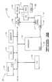
- FIG. 3is a functional block diagram of the disc drive.
- FIG. 4is a flow chart for a DATA TRANSFER routine, generally illustrative of steps carried out by the disc drive in accordance with preferred embodiments of the present invention to transfer data between the disc drive and a host device.
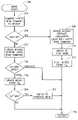
- FIG. 5is a flow chart for a MODE DETECT routine, which is executed as a subroutine of the DATA TRANSFER routine of FIG. 4 .
- FIG. 6generally illustrates a read command history table employed by the disc drive.
- FIG. 7is a timing diagram to generally illustrate operation of the disc drive in a nonlocal mode.
- FIG. 8is a timing diagram to generally illustrate operation of the disc drive in a local mode in which read look ahead (RLA) techniques are employed.
- RLAread look ahead
- FIG. 9is a timing diagram to generally illustrate operation of the disc drive in a local mode in which both read look ahead (RLA) and read on arrival (ROA) techniques are employed.
- RLAread look ahead
- ROAread on arrival
- FIG. 1provides a top plan view of a disc drive block data storage device 100 .
- the disc drive 100includes a sealed housing 101 formed by a rigid base deck 102 and a top cover 104 (shown in partial cutaway).
- Mechanical components of the disc drive 100are supported within the housing 101 , including a spindle motor 106 which rotates a number of recording discs 108 at a constant high speed, and an actuator assembly 110 supports a corresponding number of data transducing heads 112 adjacent the discs 108 .
- the actuator assemblyis rotated about an actuator axis through application of current to a coil 114 of a voice coil motor (VCM) 116 .
- VCMvoice coil motor
- FIG. 2shows a portion of a track 118 from a selected disc surface.
- the track 118includes a plurality of angularly arranged servo data fields 120 .
- the servo data fields 120provide position information used by servo control circuitry of the disc drive 100 to control the position of the heads 112 .
- User data from a host deviceare stored in data sectors defined in data areas 122 between adjacent pairs of the servo data fields 120 .
- Each data sectorstores a fixed amount of user data (such as 512 bytes) and is separately addressable by the host using a logical block address (LBA).
- LBAlogical block address
- the respective numbers of servo data fields 120 and data sectors per trackcan vary, but typical numbers for disc drives of the present generation are around 150–250 servo data fields and around 300–1000 data sectors per track.
- a typical disc drivecan thus have several million consecutively numbered LBAs, depending upon the data capacity and format of the drive.
- FIG. 3provides a functional block diagram for the disc drive 100 .
- a hardware/firmware based interface circuit 124communicates with a host device (such as a personal computer, not shown) and directs overall disc drive operation.
- the interface circuit 124includes a programmable controller (processor) 126 with associated memory 128 , a buffer 130 , an error correction code (ECC) block 132 , a sequencer 134 and an input/output (I/O) control block 136 .
- a programmable controllerprocessor
- ECCerror correction code
- I/Oinput/output
- the buffer 130(also referred to herein as a “first memory space”) temporarily stores user data during read and write operations, and includes a command queue (CQ) 131 where multiple pending access operations are temporarily stored pending execution.
- the ECC block 132applies on-the-fly error detection and correction to retrieved data.
- the sequencer 134asserts read and write gates to direct the reading and writing of data.
- the I/O block 136serves as an interface with the host device.
- FIG. 3further shows the disc drive 100 to include a read/write (R/W) channel 138 which encodes and serializes data during write operations and reconstructs user data from the discs 108 during read operations (the discs are also referred to herein as a “second memory space”).
- R/Wread/write
- a preamplifier/driver circuit (preamp) 140applies write currents to the heads 112 and provides preamplification of readback signals.
- a servo control circuit 142uses the servo data from the servo data fields 120 ( FIG. 2 ) to provide the appropriate current to the coil 114 to position the heads 112 as required.
- the servo control circuit 142preferably comprises a programmable ARM processor 144 (Advanced Reduced-Instruction-Set-Computer (RISC) Machine).
- the controller 126communicates with the ARM 144 to move the heads 112 to the desired locations on the discs 108 during execution of the various pending access commands in the command queue 131 in turn.
- RISCAdvanced Reduced-Instruction-Set-Computer
- the interface circuitry 124advantageously operates to optimize data transfer performance by dynamically switching from a nonlocal (first) mode of operation to a local (second) mode of operation in relation to a detected access pattern in read commands issued by the host device.
- a local mode of operationnonrequested user data are retrieved from the discs 108 and placed into the buffer 130 in anticipation of a future request for the nonrequested user data.
- nonrequested user dataare not retrieved from the recording medium and are not placed into the buffer.
- FIG. 4provides a flow chart for a DATA TRANSFER routine 200 , illustrative of steps carried out by the interface circuit 124 in accordance with preferred embodiments of the present invention.
- An initialization steptakes place at 202 during which the disc drive 100 is configured for use and various parameters are initially selected. Thereafter, the disc drive 100 proceeds with normal operation during which access commands are issued by the host device and received by the interface circuit 124 , as indicated at step 204 .
- each read access commandidentifies the LBAs on the discs 108 the contents of which the host requires the disc drive 100 to retrieve.
- Each write access commandincludes the write data that the host requires the disc drive 1100 to store and identifies the specific LBAs in which the disc drive is to store the write data.
- the interface circuit 124creates a command node as a sortable access instruction in the command queue 131 for each new command.
- Step 206next determines whether the new access command is a read command. If so, the routine executes a MODE DETECT subroutine 208 as discussed below. On the other hand, if the most recently received access command is a write command, the flow passes to step 210 where the drive performs write command processing, as desired. For example, if write caching is employed the interface circuit 124 will report a command complete status to the host device, temporarily store the write data in the buffer 130 , and schedule the writing of the data in the near future. If write caching is not employed, then the interface circuit 124 will give priority to the write command and schedule the writing of the data before continuing with other steps in the flow.
- the interface circuit 124performs a command sort strategy at step 212 to identify the next appropriate command node to execute in the command queue 131 , and proceeds to execute this command at step 214 . It will be noted that the receipt of new access commands and the rate at which commands are executed are asynchronous; thus, FIG. 4 has been provided with return loops to show continued operation of the above steps until the disc drive 100 is turned off or enters an idle mode.
- the MODE DETECT subroutine of FIG. 5generally operates to evaluate current data access patterns of the host device and dynamically configure the disc drive 100 accordingly to optimize data transfer performance.
- the most recently received (latest) read commandis compared to a history of recent read commands. This is preferably carried out using a read command history table as shown in FIG. 6 .
- the data in FIG. 6generally represent a localized snapshot of recent host access patterns.
- the dataare arranged along a vertical range (row axis 220 ) indicative of the most recent 16 read commands (not counting the most recently received read command under evaluation). While 16 read commands are shown, it will be understood that any selected plurality of n recent read commands can be employed as desired.
- a horizontal range (column axis 218 )indicates data sector addresses (LBAs) on the discs 108 .
- Each of the 16 read commands in FIG. 6is shown to have a range of associated data sector addresses (as indicated by block 222 for read command 1 ).
- this range of associated data sector addressescomprises a range of unrequested LBAs that could have been retrieved by the disc drive either before or (preferably) at the conclusion of each of the read commands.
- each range of address blockscomprises a number equal to the maximum number of LBAs that can be assigned to a segment of the buffer 130 .
- the data sector address blocks shown in FIG. 6do not necessarily represent nonrequested data that actually resides (or resided) in the buffer 130 ; rather, the data sector address blocks represent what potentially could have been placed into the buffer had a local mode technique been employed.
- the blocks in FIG. 6preferably represent data sector address ranges that are sequential within each range, but the data sector range of each consecutive read command in the table is non-sequential with respect to the data sector range of the previous read command (i.e., horizontal gaps exist between adjacent pairs of the blocks, as shown in FIG. 6 ).
- FIGS. 7–9have been provided to this end.
- FIG. 7is a timing diagram to illustrate nonlocal mode operation.
- Nonlocal modeis appropriate when the host device is requesting data in an apparently random fashion; that is, subsequent requests are for data sectors at nonconsecutive and nonlocal positions within the LBA addressing scheme.
- the probability of the disc drive 100 satisfying a future request for data from cached nonrequested datais very low, and the additional processing time required to place nonrequested data into the buffer 130 provides little or no benefit (and can actually reduce data transfer rates slightly).
- no nonrequested dataare placed into the buffer 130 during the nonlocal mode operation of FIG. 7 .
- FIG. 7is plotted against a horizontal time axis 224 and a vertical position axis 226 .
- First and second consecutive read commandsare carried out to retrieve data from a first set of data sectors (DATA 1 block 228 ) on a first data track 230 and then from a second set of data sectors (DATA 2 block 232 ) on a second data track 234 .
- the disc driveReading from left to right and understanding that the respective elapsed times are not necessarily represented to scale, the disc drive first transfers the DATA 1 requested data associated with the first executed read command (block 228 ).
- the controller 126instructs the servo control circuit 142 to execute a seek (block 238 ) to move a selected head 112 to the second track 234 .
- the seekmay include a head switch operation to activate and use a different selected head 112 .
- the disc drive 100incurs a latency delay (represented by latency block 240 ) during which time the drive waits for the data sectors associated with the DATA 2 block 232 to reach the selected head 112 .
- the drive 100then reads the DATA 2 block 232 and transfers this requested data to the buffer 130 for subsequent transfer to the host device.
- FIG. 8provides a timing diagram for a selected local mode of operation of the disc drive 100 .
- FIG. 8employs a read look ahead (RLA) technique.
- RLAread look ahead
- the interface circuit 124next instructs the servo control circuit 142 to execute the seek (block 238 ) to move the selected head 112 to the second track 234 and, after a short buffering time (block 244 ), transfers the requested DATA 2 data (block 232 ) to the buffer 130 .
- the time during which RLA data are obtainedis preferably determined in relation to the available elapsed time (phase) between the end of the first command and the beginning of the second command.
- phaseavailable elapsed time
- RLA datacan be accumulated for a little less than 2 ms. Since discs rotating at about 10,000 revolutions per minute require about 6 ms per rotation, then up to about a third of a track of nonrequested readback data can be obtained from the first track 230 in this example.
- FIG. 9shows a local mode that uses both read look ahead (RLA) and read on arrival (ROA) techniques.
- the interface circuit 124executes the first read command to recover the requested data from the DATA 1 block 228 , performs the necessary overhead processing at block 236 , and then performs some RLA reading of additional blocks on the first track 230 at block 242 .
- the interface circuit 124then instructs the seek 228 to occur to move the selected head 112 to the second track 234 .
- the interface circuit 124causes the head 112 to immediately start reading nonrequested data sectors upon arrival, as indicated by ROA block 246 until the DATA 2 block 232 reaches the head 112 .
- RLA and ROAcan be used as desired. Although not shown in a separate drawing, it will now be readily understood that a full ROA technique could readily be used. Such a case would have a similar timing diagram to that shown in FIG. 7 except that nonrequested ROA data would be read during the latency block 240 .
- the comparison of the most recently received read command of step 216 in FIG. 5can now be understood as evaluating a probability of whether the latest read command could have been satisfied as a cache hit out of the buffer 130 had an appropriate local mode of operation been employed among the 16 read commands in the table of FIG. 6 .
- the data sector range blocks of FIG. 6(such as 220 ) represent ranges of RLA data (that is, a range of LBAs following the last LBA associated with each read command).
- Step 248determines whether an overlap exists between the LBA (or LBAs) of the most recently received read command and the range blocks of the history table. If not, as represented by read command A (READ CMD A) 250 in FIG. 6 , the flow passes to step 252 and the history table is updated. This preferably occurs by appending the latest read command (READ CMD A) to the table. If the table is fully populated (as shown in FIG. 6 ), then the oldest entry in the table is removed and an appropriate range is calculated for the new entry.
- read command AREAD CMD A
- the routine of FIG. 5continues to decision step 254 where the controller 126 next determines which mode of operation the interface circuit 124 is currently employing. If the existing mode is nonlocal, then the fact that there would not likely have been any cache hits for the past 16 commands indicates that nonlocal mode is still the appropriate mode for the current host requirements. Thus, no changes in configuration are made and the routine returns to the flow of FIG. 4 at step 256 .
- a missed count value C Mis updated at step 258 .
- the missed count valuetracks how many noncache hits occur in a row while the local mode of operation is employed.
- the updated missed count valueis next compared at decision step 260 to a maximum allowable number of missed cache hits, C MAX . This value can be set to any desired number m, such as 16 or 32.
- step 262the mode is switched from local to nonlocal, and the routine returns at step 256 .
- the drive 100remains in local mode and the routine returns at step 256 .
- a read command B (READ CMD B) 264 of FIG. 6represents the most recently received read command. As can be observed in FIG. 6 , the read command B 264 overlaps a data range block 266 associated with read command 13 .
- step 268the history table is updated with new data associated with the read command B.
- the new datais not used to replace the oldest entry in the table; rather, the new data preferably replaces the overlapped data block 266 .
- the routinethen passes to step 270 where the mode of operation is switched to local mode.
- the mode of operationis switched to local mode.
- a block data storage device(such as 100 ) comprises a data recording medium (such as 108 ) on which user data are stored in a number of data sectors having data sector addresses (such as 122 ).
- a moveable data transducing head(such as 112 ) is provided to access the data sectors.
- An interface circuitprocesses read commands from a host device to retrieve requested user data from selected data sectors, the interface circuit dynamically switching from a nonlocal mode of operation to a local mode of operation (such as by step 262 , 270 ) in relation to proximity of a data sector address of a most recently received read command to data sector addresses associated with previously received read commands, wherein during the local mode of operation, nonrequested user data from the recording medium are retrieved and placed into a buffer in anticipation of a future request for the nonrequested user data, and wherein during the nonlocal mode of operation said nonrequested user data are not retrieved.
- the interface circuitPreferably, the interface circuit generates a read command history table (such as shown in FIG. 6 ) comprising a range of data sector addresses (such as 222 , 266 ) associated with each of a plurality of n recently received read commands.
- a read command history table(such as shown in FIG. 6 ) comprising a range of data sector addresses (such as 222 , 266 ) associated with each of a plurality of n recently received read commands.
- the interface circuitswitches from the nonlocal mode to the local mode of operation (such as by step 270 ) when a data sector address associated with the most recently received read command falls within at least a selected one of the ranges of data sector addresses of the read command history table.
- the interface circuitfurther dynamically switches from the local mode to the nonlocal mode of operation (such as by step 262 ) in relation to the proximity of the data sector address of the most recently received read command to the data sector addresses of previously received read commands.
- the recordable mediumcomprises a recording disc on which a plurality of concentric tracks (such as 118 ) are defined, and wherein during the local mode the interface circuit employs a read look ahead (RLA) technique so that, during a latency period between execution of consecutive first and second read commands, the interface circuit causes the data transducing head to remain on a first track (such as 230 ) having a data sector (such as 228 ) associated with the first read command so that the nonrequested data are retrieved from at least one other data sector (such as 242 ) on the first track.
- RLAread look ahead
- the interface circuitpreferably employs a read on arrival (ROA) technique so that, during a latency period between execution of consecutive first and second read commands, the interface circuit causes the data transducing head to move to a second track (such as 234 ) having a data sector associated with the second read command (such as 232 ) so that the nonrequested data are retrieved from at least one other data sector (such as 246 ) on the second track.
- ROIread on arrival
Landscapes
- Engineering & Computer Science (AREA)
- Theoretical Computer Science (AREA)
- Human Computer Interaction (AREA)
- Physics & Mathematics (AREA)
- General Engineering & Computer Science (AREA)
- General Physics & Mathematics (AREA)
- Signal Processing For Digital Recording And Reproducing (AREA)
Abstract
Description
Claims (18)
Priority Applications (1)
| Application Number | Priority Date | Filing Date | Title |
|---|---|---|---|
| US10/080,813US6968423B2 (en) | 2002-02-05 | 2002-02-22 | Dynamic data access pattern detection in a block data storage device |
Applications Claiming Priority (2)
| Application Number | Priority Date | Filing Date | Title |
|---|---|---|---|
| US35567502P | 2002-02-05 | 2002-02-05 | |
| US10/080,813US6968423B2 (en) | 2002-02-05 | 2002-02-22 | Dynamic data access pattern detection in a block data storage device |
Publications (2)
| Publication Number | Publication Date |
|---|---|
| US20030149837A1 US20030149837A1 (en) | 2003-08-07 |
| US6968423B2true US6968423B2 (en) | 2005-11-22 |
Family
ID=27667846
Family Applications (1)
| Application Number | Title | Priority Date | Filing Date |
|---|---|---|---|
| US10/080,813Expired - LifetimeUS6968423B2 (en) | 2002-02-05 | 2002-02-22 | Dynamic data access pattern detection in a block data storage device |
Country Status (1)
| Country | Link |
|---|---|
| US (1) | US6968423B2 (en) |
Cited By (6)
| Publication number | Priority date | Publication date | Assignee | Title |
|---|---|---|---|---|
| US20050027924A1 (en)* | 2003-06-05 | 2005-02-03 | Thomas Brune | Method for fast verification of sector addresses |
| US7437502B1 (en) | 2005-04-20 | 2008-10-14 | Western Digital Technologies, Inc. | Disk drive adjusting operating mode based on historical proximity of host commands |
| US7450334B1 (en) | 2007-06-28 | 2008-11-11 | Western Digital Technologies, Inc. | Disk drive adjusting predictive caching based on temperature of voice coil motor |
| US20080313396A1 (en)* | 2007-06-15 | 2008-12-18 | Seagate Technology, Llc | System and method of monitoring data storage activity |
| US8090902B1 (en) | 2009-05-22 | 2012-01-03 | Western Digital Technologies, Inc. | Disk drive adjusting command execution in response to control circuitry die temperature |
| US8949521B1 (en)* | 2013-04-10 | 2015-02-03 | Western Digital Technologies, Inc. | Actuator prepositioning for disk drive |
Families Citing this family (26)
| Publication number | Priority date | Publication date | Assignee | Title |
|---|---|---|---|---|
| US8286237B2 (en)* | 2003-02-25 | 2012-10-09 | Ibm International Group B.V. | Method and apparatus to detect unauthorized information disclosure via content anomaly detection |
| US8880893B2 (en)* | 2003-09-26 | 2014-11-04 | Ibm International Group B.V. | Enterprise information asset protection through insider attack specification, monitoring and mitigation |
| US7464250B2 (en)* | 2004-03-11 | 2008-12-09 | International Business Machines Corporation | Method to reduce disk access time during predictable loading sequences |
| US7199966B1 (en) | 2005-06-28 | 2007-04-03 | Western Digital Technologies, Inc. | Disk drive adjusting seek profile for variable seek times to reduce power dissipation |
| JP4721875B2 (en)* | 2005-11-04 | 2011-07-13 | 株式会社日立製作所 | Storage control method for managing access environment for host to access data |
| US20100100677A1 (en)* | 2008-10-16 | 2010-04-22 | Mckean Brian | Power and performance management using MAIDx and adaptive data placement |
| US20110035804A1 (en)* | 2009-04-07 | 2011-02-10 | Pratyush Moghe | Appliance-based parallelized analytics of data auditing events |
| US20110035781A1 (en)* | 2009-04-07 | 2011-02-10 | Pratyush Moghe | Distributed data search, audit and analytics |
| US8201001B2 (en)* | 2009-08-04 | 2012-06-12 | Lsi Corporation | Method for optimizing performance and power usage in an archival storage system by utilizing massive array of independent disks (MAID) techniques and controlled replication under scalable hashing (CRUSH) |
| US20110035547A1 (en)* | 2009-08-04 | 2011-02-10 | Kevin Kidney | Method for utilizing mirroring in a data storage system to promote improved data accessibility and improved system efficiency |
| US9720606B2 (en) | 2010-10-26 | 2017-08-01 | Avago Technologies General Ip (Singapore) Pte. Ltd. | Methods and structure for online migration of data in storage systems comprising a plurality of storage devices |
| US10146293B2 (en)* | 2014-09-22 | 2018-12-04 | Western Digital Technologies, Inc. | Performance-aware power capping control of data storage devices |
| US9965206B2 (en) | 2015-10-23 | 2018-05-08 | Western Digital Technologies, Inc. | Enhanced queue management for power control of data storage device |
| US10423336B2 (en)* | 2017-11-28 | 2019-09-24 | International Business Machines Corporation | Fast locate using imitation reads on tape drives |
| US10642502B2 (en) | 2018-06-29 | 2020-05-05 | Western Digital Technologies, Inc. | System and method for prediction of read commands to non-sequential data |
| US10649776B2 (en) | 2018-06-29 | 2020-05-12 | Western Digital Technologies, Inc. | System and method for prediction of multiple read commands directed to non-sequential data |
| US10732848B2 (en) | 2018-06-29 | 2020-08-04 | Western Digital Technologies, Inc. | System and method for predictive read of random data |
| US10846226B2 (en) | 2019-01-28 | 2020-11-24 | Western Digital Technologies, Inc. | System and method for prediction of random read commands in virtualized multi-queue memory systems |
| US10896131B2 (en) | 2019-01-28 | 2021-01-19 | Western Digital Technologies, Inc. | System and method for configuring a storage device based on prediction of host source |
| US10719445B1 (en) | 2019-02-28 | 2020-07-21 | Western Digital Technologies, Inc. | System and method for scaling a historical pattern matching data structure in a memory device |
| US10725781B1 (en) | 2019-02-28 | 2020-07-28 | Western Digital Technologies, Inc. | System and method for chain prediction of multiple read commands |
| US11055022B2 (en) | 2019-03-25 | 2021-07-06 | Western Digital Technologies, Inc. | Storage system and method for early host command fetching in a low queue depth environment |
| US11010299B2 (en) | 2019-05-20 | 2021-05-18 | Western Digital Technologies, Inc. | System and method for performing discriminative predictive read |
| US11281981B2 (en) | 2019-12-09 | 2022-03-22 | Western Digital Technologies, Inc. | Storage system and sorting-based method for random read command prediction in a multi-queue system |
| US11416263B1 (en) | 2021-02-12 | 2022-08-16 | Western Digital Technologies, Inc. | Boosted boot procedure by background re-arrangement of read patterns |
| US11257517B1 (en)* | 2021-06-14 | 2022-02-22 | Western Digital Technologies, Inc. | Data storage device seeking multiple actuators to improve performance |
Citations (17)
| Publication number | Priority date | Publication date | Assignee | Title |
|---|---|---|---|---|
| US5146578A (en)* | 1989-05-01 | 1992-09-08 | Zenith Data Systems Corporation | Method of varying the amount of data prefetched to a cache memory in dependence on the history of data requests |
| US5313626A (en) | 1991-12-17 | 1994-05-17 | Jones Craig S | Disk drive array with efficient background rebuilding |
| US5530829A (en) | 1992-12-17 | 1996-06-25 | International Business Machines Corporation | Track and record mode caching scheme for a storage system employing a scatter index table with pointer and a track directory |
| US5570332A (en) | 1995-05-25 | 1996-10-29 | Seagate Technology, Inc. | Method for reducing rotational latency in a disc drive |
| US5584007A (en) | 1994-02-09 | 1996-12-10 | Ballard Synergy Corporation | Apparatus and method for discriminating among data to be stored in cache |
| US5636355A (en) | 1993-06-30 | 1997-06-03 | Digital Equipment Corporation | Disk cache management techniques using non-volatile storage |
| US5664145A (en) | 1991-02-19 | 1997-09-02 | International Business Machines Corporation | Apparatus and method for transferring data in a data storage subsystems wherein a multi-sector data transfer order is executed while a subsequent order is issued |
| US5682500A (en)* | 1992-06-04 | 1997-10-28 | Emc Corporation | System and method for determining sequential cache data access in progress |
| US5727183A (en) | 1995-03-15 | 1998-03-10 | Fujitsu Limited | Data transfer between disk storage and host device under the control of file control device employing cache and associated batch write-back operation |
| US5829018A (en) | 1994-10-25 | 1998-10-27 | International Business Machines Corporation | Apparatus and method for writing data from a cache to a storage device |
| US5875455A (en) | 1994-06-10 | 1999-02-23 | Matsushita Electric Industrial Co., Ltd. | Information recording and reproducing apparatus merging sequential recording requests into a single recording request, and method of data caching for such apparatus |
| US6164840A (en) | 1997-06-24 | 2000-12-26 | Sun Microsystems, Inc. | Ensuring consistency of an instruction cache with a store cache check and an execution blocking flush instruction in an instruction queue |
| US6189080B1 (en) | 1996-09-20 | 2001-02-13 | Emc Corporation | Minimum read rate throughput in a disk cache system |
| US6263408B1 (en) | 1999-03-31 | 2001-07-17 | International Business Machines Corporation | Method and apparatus for implementing automatic cache variable update |
| US6339811B1 (en)* | 1999-04-21 | 2002-01-15 | Seagate Technologh Llc | Rotationally optimized seek initiation |
| US20030018849A1 (en)* | 2000-03-31 | 2003-01-23 | Noriaki Takaichi | Disk memory device, data pre-reading method, and recorded medium |
| US6654850B2 (en)* | 2001-03-26 | 2003-11-25 | Seagate Technology Llc | Parametric optimization of a disc drive through I/O command sequence analysis |
- 2002
- 2002-02-22USUS10/080,813patent/US6968423B2/ennot_activeExpired - Lifetime
Patent Citations (18)
| Publication number | Priority date | Publication date | Assignee | Title |
|---|---|---|---|---|
| US5146578A (en)* | 1989-05-01 | 1992-09-08 | Zenith Data Systems Corporation | Method of varying the amount of data prefetched to a cache memory in dependence on the history of data requests |
| US5664145A (en) | 1991-02-19 | 1997-09-02 | International Business Machines Corporation | Apparatus and method for transferring data in a data storage subsystems wherein a multi-sector data transfer order is executed while a subsequent order is issued |
| US5313626A (en) | 1991-12-17 | 1994-05-17 | Jones Craig S | Disk drive array with efficient background rebuilding |
| US5682500A (en)* | 1992-06-04 | 1997-10-28 | Emc Corporation | System and method for determining sequential cache data access in progress |
| US5530829A (en) | 1992-12-17 | 1996-06-25 | International Business Machines Corporation | Track and record mode caching scheme for a storage system employing a scatter index table with pointer and a track directory |
| US5636355A (en) | 1993-06-30 | 1997-06-03 | Digital Equipment Corporation | Disk cache management techniques using non-volatile storage |
| US5584007A (en) | 1994-02-09 | 1996-12-10 | Ballard Synergy Corporation | Apparatus and method for discriminating among data to be stored in cache |
| US5875455A (en) | 1994-06-10 | 1999-02-23 | Matsushita Electric Industrial Co., Ltd. | Information recording and reproducing apparatus merging sequential recording requests into a single recording request, and method of data caching for such apparatus |
| US5983319A (en) | 1994-06-10 | 1999-11-09 | Matsushita Electric Industrial Co., Ltd. | Information recording and reproduction apparatus and a method of data caching including read-ahead capability |
| US5829018A (en) | 1994-10-25 | 1998-10-27 | International Business Machines Corporation | Apparatus and method for writing data from a cache to a storage device |
| US5727183A (en) | 1995-03-15 | 1998-03-10 | Fujitsu Limited | Data transfer between disk storage and host device under the control of file control device employing cache and associated batch write-back operation |
| US5570332A (en) | 1995-05-25 | 1996-10-29 | Seagate Technology, Inc. | Method for reducing rotational latency in a disc drive |
| US6189080B1 (en) | 1996-09-20 | 2001-02-13 | Emc Corporation | Minimum read rate throughput in a disk cache system |
| US6164840A (en) | 1997-06-24 | 2000-12-26 | Sun Microsystems, Inc. | Ensuring consistency of an instruction cache with a store cache check and an execution blocking flush instruction in an instruction queue |
| US6263408B1 (en) | 1999-03-31 | 2001-07-17 | International Business Machines Corporation | Method and apparatus for implementing automatic cache variable update |
| US6339811B1 (en)* | 1999-04-21 | 2002-01-15 | Seagate Technologh Llc | Rotationally optimized seek initiation |
| US20030018849A1 (en)* | 2000-03-31 | 2003-01-23 | Noriaki Takaichi | Disk memory device, data pre-reading method, and recorded medium |
| US6654850B2 (en)* | 2001-03-26 | 2003-11-25 | Seagate Technology Llc | Parametric optimization of a disc drive through I/O command sequence analysis |
Cited By (8)
| Publication number | Priority date | Publication date | Assignee | Title |
|---|---|---|---|---|
| US20050027924A1 (en)* | 2003-06-05 | 2005-02-03 | Thomas Brune | Method for fast verification of sector addresses |
| US7266666B2 (en)* | 2003-06-05 | 2007-09-04 | Thomson Licensing | Method for fast verification of sector addresses |
| US7437502B1 (en) | 2005-04-20 | 2008-10-14 | Western Digital Technologies, Inc. | Disk drive adjusting operating mode based on historical proximity of host commands |
| US20080313396A1 (en)* | 2007-06-15 | 2008-12-18 | Seagate Technology, Llc | System and method of monitoring data storage activity |
| US8032699B2 (en)* | 2007-06-15 | 2011-10-04 | Seagate Technology Llc | System and method of monitoring data storage activity |
| US7450334B1 (en) | 2007-06-28 | 2008-11-11 | Western Digital Technologies, Inc. | Disk drive adjusting predictive caching based on temperature of voice coil motor |
| US8090902B1 (en) | 2009-05-22 | 2012-01-03 | Western Digital Technologies, Inc. | Disk drive adjusting command execution in response to control circuitry die temperature |
| US8949521B1 (en)* | 2013-04-10 | 2015-02-03 | Western Digital Technologies, Inc. | Actuator prepositioning for disk drive |
Also Published As
| Publication number | Publication date |
|---|---|
| US20030149837A1 (en) | 2003-08-07 |
Similar Documents
| Publication | Publication Date | Title |
|---|---|---|
| US6968423B2 (en) | Dynamic data access pattern detection in a block data storage device | |
| US6789163B2 (en) | Optimizing data transfer performance through partial write command purging in a disc drive | |
| US7437502B1 (en) | Disk drive adjusting operating mode based on historical proximity of host commands | |
| US6732292B2 (en) | Adaptive bi-directional write skip masks in a data storage device | |
| US6789162B1 (en) | Storage controller configured to select unused regions of a storage device for data storage according to head position | |
| US8560759B1 (en) | Hybrid drive storing redundant copies of data on disk and in non-volatile semiconductor memory based on read frequency | |
| US8819375B1 (en) | Method for selective defragmentation in a data storage device | |
| US6925539B2 (en) | Data transfer performance through resource allocation | |
| KR100228795B1 (en) | Method for improving the function of read/write of track | |
| KR20020064357A (en) | Buffer management system for managing the transfer of data into and out of a buffer in a disc drive | |
| US10152236B2 (en) | Hybrid data storage device with partitioned local memory | |
| US6957311B2 (en) | Data storage apparatus, computer apparatus, data processing apparatus, and data processing method | |
| US6523142B1 (en) | Apparatus and method of performing in a disk drive commands issued from a host system | |
| US20010032292A1 (en) | Implementation of skip mask hardware in a disc drive | |
| KR19980029917A (en) | How to improve read cache performance on magnetic disk drives | |
| US8117491B2 (en) | Disk-drive device and method for error recovery thereof | |
| US7253981B2 (en) | Disc drive with reduced write latency | |
| US20080155166A1 (en) | Application specific processor for controlling data buffer manager | |
| US6957300B2 (en) | Reducing delay of command completion due to overlap condition | |
| US10459658B2 (en) | Hybrid data storage device with embedded command queuing | |
| US6792504B2 (en) | Read on arrival scheme for a disc drive | |
| US20080313396A1 (en) | System and method of monitoring data storage activity | |
| US6725330B1 (en) | Adaptable cache for disc drive | |
| US20090002863A1 (en) | System and method of monitoring data operations at a data storage device | |
| WO2000067250A2 (en) | Methods and systems for mirrored disk arrays |
Legal Events
| Date | Code | Title | Description |
|---|---|---|---|
| AS | Assignment | Owner name:SEAGATE TECHNOLOGY LLC, CALIFORNIA Free format text:ASSIGNMENT OF ASSIGNORS INTEREST;ASSIGNORS:COKER, KENNY T.;OLDS, EDWIN S.;MOBLEY, JACK A.;REEL/FRAME:012918/0780 Effective date:20020403 | |
| AS | Assignment | Owner name:JPMORGAN CHASE BANK, AS COLLATERAL AGENT, NEW YORK Free format text:SECURITY AGREEMENT;ASSIGNOR:SEAGATE TECHNOLOGY LLC;REEL/FRAME:013177/0001 Effective date:20020513 Owner name:JPMORGAN CHASE BANK, AS COLLATERAL AGENT,NEW YORK Free format text:SECURITY AGREEMENT;ASSIGNOR:SEAGATE TECHNOLOGY LLC;REEL/FRAME:013177/0001 Effective date:20020513 | |
| FEPP | Fee payment procedure | Free format text:PAYOR NUMBER ASSIGNED (ORIGINAL EVENT CODE: ASPN); ENTITY STATUS OF PATENT OWNER: LARGE ENTITY | |
| STCF | Information on status: patent grant | Free format text:PATENTED CASE | |
| AS | Assignment | Owner name:WELLS FARGO BANK, NATIONAL ASSOCIATION, AS COLLATERAL AGENT AND SECOND PRIORITY REPRESENTATIVE, CALIFORNIA Free format text:SECURITY AGREEMENT;ASSIGNORS:MAXTOR CORPORATION;SEAGATE TECHNOLOGY LLC;SEAGATE TECHNOLOGY INTERNATIONAL;REEL/FRAME:022757/0017 Effective date:20090507 Owner name:JPMORGAN CHASE BANK, N.A., AS ADMINISTRATIVE AGENT AND FIRST PRIORITY REPRESENTATIVE, NEW YORK Free format text:SECURITY AGREEMENT;ASSIGNORS:MAXTOR CORPORATION;SEAGATE TECHNOLOGY LLC;SEAGATE TECHNOLOGY INTERNATIONAL;REEL/FRAME:022757/0017 Effective date:20090507 Owner name:JPMORGAN CHASE BANK, N.A., AS ADMINISTRATIVE AGENT Free format text:SECURITY AGREEMENT;ASSIGNORS:MAXTOR CORPORATION;SEAGATE TECHNOLOGY LLC;SEAGATE TECHNOLOGY INTERNATIONAL;REEL/FRAME:022757/0017 Effective date:20090507 Owner name:WELLS FARGO BANK, NATIONAL ASSOCIATION, AS COLLATE Free format text:SECURITY AGREEMENT;ASSIGNORS:MAXTOR CORPORATION;SEAGATE TECHNOLOGY LLC;SEAGATE TECHNOLOGY INTERNATIONAL;REEL/FRAME:022757/0017 Effective date:20090507 | |
| FPAY | Fee payment | Year of fee payment:4 | |
| AS | Assignment | Owner name:MAXTOR CORPORATION, CALIFORNIA Free format text:RELEASE;ASSIGNOR:JPMORGAN CHASE BANK, N.A., AS ADMINISTRATIVE AGENT;REEL/FRAME:025662/0001 Effective date:20110114 Owner name:SEAGATE TECHNOLOGY INTERNATIONAL, CALIFORNIA Free format text:RELEASE;ASSIGNOR:JPMORGAN CHASE BANK, N.A., AS ADMINISTRATIVE AGENT;REEL/FRAME:025662/0001 Effective date:20110114 Owner name:SEAGATE TECHNOLOGY LLC, CALIFORNIA Free format text:RELEASE;ASSIGNOR:JPMORGAN CHASE BANK, N.A., AS ADMINISTRATIVE AGENT;REEL/FRAME:025662/0001 Effective date:20110114 Owner name:SEAGATE TECHNOLOGY HDD HOLDINGS, CALIFORNIA Free format text:RELEASE;ASSIGNOR:JPMORGAN CHASE BANK, N.A., AS ADMINISTRATIVE AGENT;REEL/FRAME:025662/0001 Effective date:20110114 | |
| AS | Assignment | Owner name:THE BANK OF NOVA SCOTIA, AS ADMINISTRATIVE AGENT, CANADA Free format text:SECURITY AGREEMENT;ASSIGNOR:SEAGATE TECHNOLOGY LLC;REEL/FRAME:026010/0350 Effective date:20110118 Owner name:THE BANK OF NOVA SCOTIA, AS ADMINISTRATIVE AGENT, Free format text:SECURITY AGREEMENT;ASSIGNOR:SEAGATE TECHNOLOGY LLC;REEL/FRAME:026010/0350 Effective date:20110118 | |
| FPAY | Fee payment | Year of fee payment:8 | |
| AS | Assignment | Owner name:SEAGATE TECHNOLOGY US HOLDINGS, INC., CALIFORNIA Free format text:TERMINATION AND RELEASE OF SECURITY INTEREST IN PATENT RIGHTS;ASSIGNOR:WELLS FARGO BANK, NATIONAL ASSOCIATION, AS COLLATERAL AGENT AND SECOND PRIORITY REPRESENTATIVE;REEL/FRAME:030833/0001 Effective date:20130312 Owner name:SEAGATE TECHNOLOGY INTERNATIONAL, CAYMAN ISLANDS Free format text:TERMINATION AND RELEASE OF SECURITY INTEREST IN PATENT RIGHTS;ASSIGNOR:WELLS FARGO BANK, NATIONAL ASSOCIATION, AS COLLATERAL AGENT AND SECOND PRIORITY REPRESENTATIVE;REEL/FRAME:030833/0001 Effective date:20130312 Owner name:SEAGATE TECHNOLOGY LLC, CALIFORNIA Free format text:TERMINATION AND RELEASE OF SECURITY INTEREST IN PATENT RIGHTS;ASSIGNOR:WELLS FARGO BANK, NATIONAL ASSOCIATION, AS COLLATERAL AGENT AND SECOND PRIORITY REPRESENTATIVE;REEL/FRAME:030833/0001 Effective date:20130312 Owner name:EVAULT INC. (F/K/A I365 INC.), CALIFORNIA Free format text:TERMINATION AND RELEASE OF SECURITY INTEREST IN PATENT RIGHTS;ASSIGNOR:WELLS FARGO BANK, NATIONAL ASSOCIATION, AS COLLATERAL AGENT AND SECOND PRIORITY REPRESENTATIVE;REEL/FRAME:030833/0001 Effective date:20130312 | |
| FPAY | Fee payment | Year of fee payment:12 | |
| AS | Assignment | Owner name:SEAGATE TECHNOLOGY PUBLIC LIMITED COMPANY, CALIFORNIA Free format text:RELEASE BY SECURED PARTY;ASSIGNOR:THE BANK OF NOVA SCOTIA;REEL/FRAME:072193/0001 Effective date:20250303 Owner name:SEAGATE TECHNOLOGY, CALIFORNIA Free format text:RELEASE BY SECURED PARTY;ASSIGNOR:THE BANK OF NOVA SCOTIA;REEL/FRAME:072193/0001 Effective date:20250303 Owner name:SEAGATE TECHNOLOGY HDD HOLDINGS, CALIFORNIA Free format text:RELEASE BY SECURED PARTY;ASSIGNOR:THE BANK OF NOVA SCOTIA;REEL/FRAME:072193/0001 Effective date:20250303 Owner name:I365 INC., CALIFORNIA Free format text:RELEASE BY SECURED PARTY;ASSIGNOR:THE BANK OF NOVA SCOTIA;REEL/FRAME:072193/0001 Effective date:20250303 Owner name:SEAGATE TECHNOLOGY LLC, CALIFORNIA Free format text:RELEASE BY SECURED PARTY;ASSIGNOR:THE BANK OF NOVA SCOTIA;REEL/FRAME:072193/0001 Effective date:20250303 Owner name:SEAGATE TECHNOLOGY INTERNATIONAL, CAYMAN ISLANDS Free format text:RELEASE BY SECURED PARTY;ASSIGNOR:THE BANK OF NOVA SCOTIA;REEL/FRAME:072193/0001 Effective date:20250303 Owner name:SEAGATE HDD CAYMAN, CAYMAN ISLANDS Free format text:RELEASE BY SECURED PARTY;ASSIGNOR:THE BANK OF NOVA SCOTIA;REEL/FRAME:072193/0001 Effective date:20250303 Owner name:SEAGATE TECHNOLOGY (US) HOLDINGS, INC., CALIFORNIA Free format text:RELEASE BY SECURED PARTY;ASSIGNOR:THE BANK OF NOVA SCOTIA;REEL/FRAME:072193/0001 Effective date:20250303 |