US6968343B2 - Methods and systems for integrating process modeling and project planning - Google Patents
Methods and systems for integrating process modeling and project planningDownload PDFInfo
- Publication number
- US6968343B2 US6968343B2US09/944,697US94469701AUS6968343B2US 6968343 B2US6968343 B2US 6968343B2US 94469701 AUS94469701 AUS 94469701AUS 6968343 B2US6968343 B2US 6968343B2
- Authority
- US
- United States
- Prior art keywords
- task
- workflow
- plan
- predecessor
- different
- Prior art date
- Legal status (The legal status is an assumption and is not a legal conclusion. Google has not performed a legal analysis and makes no representation as to the accuracy of the status listed.)
- Expired - Fee Related, expires
Links
Images


Classifications
- G—PHYSICS
- G06—COMPUTING OR CALCULATING; COUNTING
- G06Q—INFORMATION AND COMMUNICATION TECHNOLOGY [ICT] SPECIALLY ADAPTED FOR ADMINISTRATIVE, COMMERCIAL, FINANCIAL, MANAGERIAL OR SUPERVISORY PURPOSES; SYSTEMS OR METHODS SPECIALLY ADAPTED FOR ADMINISTRATIVE, COMMERCIAL, FINANCIAL, MANAGERIAL OR SUPERVISORY PURPOSES, NOT OTHERWISE PROVIDED FOR
- G06Q10/00—Administration; Management
- G06Q10/06—Resources, workflows, human or project management; Enterprise or organisation planning; Enterprise or organisation modelling
- G06Q10/063—Operations research, analysis or management
- G06Q10/0633—Workflow analysis
- G—PHYSICS
- G06—COMPUTING OR CALCULATING; COUNTING
- G06Q—INFORMATION AND COMMUNICATION TECHNOLOGY [ICT] SPECIALLY ADAPTED FOR ADMINISTRATIVE, COMMERCIAL, FINANCIAL, MANAGERIAL OR SUPERVISORY PURPOSES; SYSTEMS OR METHODS SPECIALLY ADAPTED FOR ADMINISTRATIVE, COMMERCIAL, FINANCIAL, MANAGERIAL OR SUPERVISORY PURPOSES, NOT OTHERWISE PROVIDED FOR
- G06Q10/00—Administration; Management
- G06Q10/06—Resources, workflows, human or project management; Enterprise or organisation planning; Enterprise or organisation modelling
- G06Q10/063—Operations research, analysis or management
- G06Q10/0631—Resource planning, allocation, distributing or scheduling for enterprises or organisations
- G06Q10/06311—Scheduling, planning or task assignment for a person or group
- G06Q10/063116—Schedule adjustment for a person or group
- G—PHYSICS
- G06—COMPUTING OR CALCULATING; COUNTING
- G06Q—INFORMATION AND COMMUNICATION TECHNOLOGY [ICT] SPECIALLY ADAPTED FOR ADMINISTRATIVE, COMMERCIAL, FINANCIAL, MANAGERIAL OR SUPERVISORY PURPOSES; SYSTEMS OR METHODS SPECIALLY ADAPTED FOR ADMINISTRATIVE, COMMERCIAL, FINANCIAL, MANAGERIAL OR SUPERVISORY PURPOSES, NOT OTHERWISE PROVIDED FOR
- G06Q10/00—Administration; Management
- G06Q10/06—Resources, workflows, human or project management; Enterprise or organisation planning; Enterprise or organisation modelling
- G06Q10/063—Operations research, analysis or management
- G06Q10/0631—Resource planning, allocation, distributing or scheduling for enterprises or organisations
- G06Q10/06312—Adjustment or analysis of established resource schedule, e.g. resource or task levelling, or dynamic rescheduling
- G—PHYSICS
- G06—COMPUTING OR CALCULATING; COUNTING
- G06Q—INFORMATION AND COMMUNICATION TECHNOLOGY [ICT] SPECIALLY ADAPTED FOR ADMINISTRATIVE, COMMERCIAL, FINANCIAL, MANAGERIAL OR SUPERVISORY PURPOSES; SYSTEMS OR METHODS SPECIALLY ADAPTED FOR ADMINISTRATIVE, COMMERCIAL, FINANCIAL, MANAGERIAL OR SUPERVISORY PURPOSES, NOT OTHERWISE PROVIDED FOR
- G06Q10/00—Administration; Management
- G06Q10/10—Office automation; Time management
- G—PHYSICS
- G06—COMPUTING OR CALCULATING; COUNTING
- G06Q—INFORMATION AND COMMUNICATION TECHNOLOGY [ICT] SPECIALLY ADAPTED FOR ADMINISTRATIVE, COMMERCIAL, FINANCIAL, MANAGERIAL OR SUPERVISORY PURPOSES; SYSTEMS OR METHODS SPECIALLY ADAPTED FOR ADMINISTRATIVE, COMMERCIAL, FINANCIAL, MANAGERIAL OR SUPERVISORY PURPOSES, NOT OTHERWISE PROVIDED FOR
- G06Q30/00—Commerce
- G06Q30/06—Buying, selling or leasing transactions
- Y—GENERAL TAGGING OF NEW TECHNOLOGICAL DEVELOPMENTS; GENERAL TAGGING OF CROSS-SECTIONAL TECHNOLOGIES SPANNING OVER SEVERAL SECTIONS OF THE IPC; TECHNICAL SUBJECTS COVERED BY FORMER USPC CROSS-REFERENCE ART COLLECTIONS [XRACs] AND DIGESTS
- Y10—TECHNICAL SUBJECTS COVERED BY FORMER USPC
- Y10S—TECHNICAL SUBJECTS COVERED BY FORMER USPC CROSS-REFERENCE ART COLLECTIONS [XRACs] AND DIGESTS
- Y10S707/00—Data processing: database and file management or data structures
- Y10S707/99941—Database schema or data structure
- Y10S707/99942—Manipulating data structure, e.g. compression, compaction, compilation
- Y—GENERAL TAGGING OF NEW TECHNOLOGICAL DEVELOPMENTS; GENERAL TAGGING OF CROSS-SECTIONAL TECHNOLOGIES SPANNING OVER SEVERAL SECTIONS OF THE IPC; TECHNICAL SUBJECTS COVERED BY FORMER USPC CROSS-REFERENCE ART COLLECTIONS [XRACs] AND DIGESTS
- Y10—TECHNICAL SUBJECTS COVERED BY FORMER USPC
- Y10S—TECHNICAL SUBJECTS COVERED BY FORMER USPC CROSS-REFERENCE ART COLLECTIONS [XRACs] AND DIGESTS
- Y10S707/00—Data processing: database and file management or data structures
- Y10S707/99941—Database schema or data structure
- Y10S707/99943—Generating database or data structure, e.g. via user interface
- Y—GENERAL TAGGING OF NEW TECHNOLOGICAL DEVELOPMENTS; GENERAL TAGGING OF CROSS-SECTIONAL TECHNOLOGIES SPANNING OVER SEVERAL SECTIONS OF THE IPC; TECHNICAL SUBJECTS COVERED BY FORMER USPC CROSS-REFERENCE ART COLLECTIONS [XRACs] AND DIGESTS
- Y10—TECHNICAL SUBJECTS COVERED BY FORMER USPC
- Y10S—TECHNICAL SUBJECTS COVERED BY FORMER USPC CROSS-REFERENCE ART COLLECTIONS [XRACs] AND DIGESTS
- Y10S707/00—Data processing: database and file management or data structures
- Y10S707/99941—Database schema or data structure
- Y10S707/99944—Object-oriented database structure
- Y10S707/99945—Object-oriented database structure processing
Definitions
- the present inventionrelates to a method and system for integrating a business process or workflow with a project plan. More particularly, the invention relates to a method and system for creating and activating a project plan based on a workflow, for managing the execution of the activated project plan, and for tracking the progress of the activated project plan.
- a workflowis a model of a process. More specifically, a workflow can be viewed as a structured set of activities designed to produce a specific output for a particular customer (internal or external to an enterprise) or market.
- conventional software toolsdefine the steps performed by the workflow, conventional tools do not schedule the resources (e.g., the people, equipment, or software technologies) responsible for completing each activity. Conventional tools also do not prepare a timeline identifying the beginning or end of each activity. Thus, conventional tools do not prepare a schedule for completing the workflow.
- a planrepresents an instance of the workflow. More specifically, a plan can be viewed as a working schedule for a project to produce a product or artifact, such as a computer, bicycle, or software build, for the respective enterprise.
- These other conventional software toolstypically display the working schedule in the form of an interactive Gantt chart, i.e., a chart to which the user can make updates.
- Gantt chartis the linear, time-based representation of a project schedule, usually laid out on a horizontal plane where the times/dates increase to the right. These Gantt charts show the temporal relationships between the different tasks in a project, where the tasks are arranged along the vertical axis.
- Gantt chartsare typically used to lay out an initial plan/timeline for the project, and then to track the actual progress of a project from start to finish.
- the modem software-based Gantt chartalso identifies the resource(s) responsible for completing each task of the plan, the dependencies between the tasks, and, once the project has begun, the status of each task.
- Methods and systems consistent with the present inventionprovide a workflow modeling and project planning integration tool that overcomes the limitations of conventional tools. Contrary to conventional tools that do not allow a user to integrate a business process or workflow with a project plan, the integration tool, in accordance with methods and systems consistent with the present invention, allows a user to model a business process or workflow, to create and activate or start a project plan based on the workflow, to manage the execution of the activated plan, and to track the progress of the activated project plan.
- the toolmay include a Web-based “Distributed Authoring and Versioning” server that operates as a virtual file system to allow more than one user to view the same workflow or project plan, to provide persistent storage, to monitor the progress of an activated project plan, to simultaneously create plans from the same workflow, and to have essentially unlimited access to the power of the tool through the ubiquity of the Internet.
- “Versioningis a term well-known in the art for capturing the state of an entity at given points in time.
- a methodin a data processing system.
- the methodcomprises the steps of creating a workflow that models a process and generating a plan from the workflow that represents an instance of the process.
- a methodis provided in a data processing system.
- the data processing systemhas a workflow that models a process.
- the methodcomprises the steps of generating a plan from the workflow that reflects an instance of the process and activating the plan to perform the instance of the process.
- a methodis provided in a data processing system.
- the data processing systemhas a virtual file system server connected to a network storage medium.
- the methodcomprises the steps of using the virtual file system server to retrieve a workflow from the network storage medium, creating a plan from the workflow, and storing the plan on the network storage medium
- a computer-readable mediumcontains instructions for controlling a data processing system to perform a method.
- the data processing systemcomprises a virtual file system server connected to a network storage medium.
- the methodcomprises the steps of using the virtual file system server to retrieve an activity having a duration from the network storage medium, creating a task from the activity, and storing the task on the network storage medium.
- the step of creating the taskcomprises the steps of receiving an indication of a start time for the task, and setting an end time for the task equal to the duration after the start time.
- a computer-readable mediumcontains instructions for controlling a data processing system to perform a method.
- the data processing systemcomprises an activity with a duration.
- the methodcomprises the steps of creating a task from the activity, and creating a different task from the activity.
- the step of creating the taskcomprises the steps of receiving an indication of a start time for the task, and setting an end time for the task equal to the duration after the start time.
- the step of creating the different taskcomprises the steps of receiving an indication of a different start time for the task, and setting an end time for the task equal to the duration after the different start time.
- a computer-readable mediumcontains instructions for controlling a data processing system to perform a method.
- the data processing systemcomprises an activity with a duration.
- the methodcomprises the steps of creating a task from the activity, and creating a different task from the activity.
- the step of creating the taskcomprises the steps of receiving user input indicating a resource assigned to the task, receiving an indication of a start time for the task, and setting an end time for the task equal to the duration after the start time.
- the step of creating the different taskcomprises the steps of receiving user input indicating a different resource assigned to the different task, receiving an indication of the start time for the task, and setting an end time for the different task equal to the duration after the start time.
- a computer-readable mediumcontains instructions for controlling a data processing system to perform a method.
- the data processing systemcomprises a plurality of activities wherein each of the activities has a duration and wherein a predecessor one of the plurality of activities occurs before a successor one of the plurality of activities.
- the methodcomprises the steps of creating a predecessor task from the predecessor activity, and creating a successor task from the successor activity.
- the step of creating the predecessor taskcomprises the steps of receiving an indication of a start time for the predecessor task, and setting a predecessor end time for the predecessor task equal to the predecessor duration after the start time.
- the step of creating the successor taskcomprises the steps of setting a successor start time equal to the predecessor end time, and setting a successor end time equal to the successor duration after the successor start time.
- a computer-readable mediumcontains instructions for controlling a data processing system to perform a method.
- the data processing systemcomprises a plurality of activities wherein each of the activities has a duration and wherein one of the plurality of activities and another of the plurality of activities start and end at a same time.
- the methodcomprises the steps of creating a task from the activity, and creating another task from the other activity.
- the step of creating the taskcomprises the steps of receiving an indication of a start time for the task, and setting an end time for the task equal to the duration after the start time.
- the step of creating the other taskcomprises the steps of setting another start time for the other task equal to the start time for the task, and setting another end time equal to the other duration after the start time.
- a computer-readable mediumcontains instructions for controlling a data processing system to perform a method.
- the methodcomprises the steps of creating a workflow that models a process, and generating a plan from the workflow that represents an instance of the process.
- a computer-readable mediumcontains instructions for controlling a data processing system to perform a method.
- the data processing systemcomprises a workflow that models a process.
- the methodcomprises the steps of generating a plan from the workflow that reflects an instance of the process, and activating the plan to perform the instance of the process.
- a computer-readable mediumcontains instructions for controlling a data processing system to perform a method.
- the data processing systemcomprises a virtual file system server connected to a network storage medium.
- the methodcomprises the steps of using the virtual file system server to retrieve a workflow from the network storage medium, generating a plan from the workflow, and storing the plan on the network storage medium.
- FIG. 1depicts a data processing system suitable for practicing methods and systems consistent with the present invention
- FIG. 2depicts an architectural overview of the workflow modeling and project planning integration tool used to perform methods and systems consistent with the present invention
- FIG. 3depicts a flow diagram illustrating the high-level process performed by the tool of FIG. 2 in accordance with methods and systems consistent with the present invention
- FIG. 4depicts an exemplary document workflow modeled by an enterprise affiliate using the tool of FIG. 2 ;
- FIG. 5depicts an exemplary task workflow modeled by an enterprise affiliate using the tool of FIG. 2 ;
- FIG. 6depicts another exemplary workflow modeled by an enterprise affiliate using the tool of FIG. 2 ;
- FIG. 7depicts a timeline of the task created from the workflow of FIG. 4 ;
- FIG. 8depicts a timeline of the task created from the workflow of FIG. 5 ;
- FIGS. 10-12depict the execution of the plan depicted in FIG. 7 ;
- FIGS. 13-16depict the execution of the plan depicted in FIG. 8 ;
- FIGS. 17-21depict the execution of the plan depicted in FIG. 9 following the default path
- FIGS. 22-27depict the execution of the plan depicted in FIG. 9 following the non-default path
- FIGS. 28A-Cdepict a flow diagram illustrating the creation or retrieval of a workflow by the tool of FIG. 2 ;
- FIG. 30depicts an exemplary user interface of the tool of FIG. 2 used to enter the name of a new workflow group
- FIG. 31depicts an exemplary user interface of the tool of FIG. 2 used to begin creating a new workflow
- FIG. 32depicts an exemplary user interface of the tool of FIG. 2 used to enter the name of a new workflow
- FIG. 33A-Cdepict an exemplary workflow definition file produced by the tool of FIG. 2 for the workflow depicted in FIG. 6 ;
- FIG. 34depicts an exemplary user interface of the tool of FIG. 2 used to manage a workflow
- FIG. 35depicts an exemplary user interface of the tool of FIG. 2 used to add a new role to a workflow
- FIG. 36depicts an exemplary user interface of the tool of FIG. 2 used to select an artifact type
- FIG. 37depicts an exemplary user interface of the tool of FIG. 2 used to enter condition properties for a document-oriented artifact
- FIG. 38depicts an exemplary user interface of the tool of FIG. 2 used to enter condition properties for a script-oriented artifact
- FIG. 39depicts an exemplary user interface of a script editor for the tool of FIG. 2 ;
- FIG. 40depicts an exemplary user interface of the tool of FIG. 2 used to modify the properties of a workflow activity
- FIGS. 41A and Bdepict a flow diagram illustrating the creation of a plan from a workflow
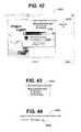
- FIG. 42depicts an exemplary user interface of the tool of FIG. 2 used to create a new plan group
- FIG. 43depicts an exemplary user interface of the tool of FIG. 2 displaying the available plan groups
- FIG. 44depicts an exemplary user interface of the tool of FIG. 2 used to enter a plan name
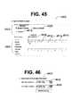
- FIG. 45depicts an exemplary user interface of the tool of FIG. 2 used to enter the working schedule
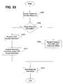
- FIG. 46depicts an exemplary user interface of the tool of FIG. 2 used to enter the scheduled start and end times for the plan;
- FIG. 47depicts an exemplary workflow definition file produced by the tool of FIG. 2 for the workflow of FIG. 5 is created
- FIG. 48depicts an exemplary plan definition file created from the workflow definition file of FIG. 47 ;
- FIG. 49depicts an exemplary user interface of the tool of FIG. 2 used to assign users to a plan
- FIG. 50depicts an exemplary user interface of the tool of FIG. 2 used to edit the properties of a plan
- FIG. 51depicts a timeline of the task created from the workflow of FIG. 5 ;
- FIG. 52depicts an exemplary timeline of the tool of FIG. 2 used to activate a plan
- FIG. 53depicts a flow diagram illustrating the addition of a resource by the tool of FIG. 2 ;
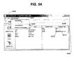
- FIG. 54depicts an exemplary user interface of the tool of FIG. 2 used to add a resource
- FIG. 55depicts an exemplary user interface of the tool of FIG. 2 used to receive LDAP access information
- FIG. 56depicts an exemplary resource file created by the tool of FIG. 2 ;
- FIG. 57depicts a flow diagram illustrating the management of an activated plan
- FIG. 58depicts a timeline of the task created from the workflow of FIG. 5 ;
- FIG. 59depicts an exemplary plan definition file created from the workflow of FIG. 5 ;
- FIGS. 60 , 62 , 64 and 66depict the actual timeline showing the execution of the plan depicted in FIG. 58 ;
- FIGS. 61 , 63 , and 65depict the properties of the executing tasks of FIGS. 62 , 64 , and 66 .
- Methods and systems consistent with the present inventionprovide an integrated workflow modeling and project planning integration tool that improves the efficiency and reduces the operating cost of an enterprise or business conglomerate. Contrary to conventional tools that do not allow a user to integrate a workflow and a project plan, the integration tool allows a user to model a business process or workflow, to create and activate a project plan based on the workflow, and to track the progress of the activated project plan. The tool also allows the workflow to be reused to create more than one project plan based on the workflow. The tool simultaneously manages the execution of the plans.
- the integration toolmay include a virtual file system server, such as a Web-based “Distributed Authoring and Versioning” (WebDAV) server that operates as a virtual file system for computers on a network. With the WebDAV server, more than one user on different computer systems may view the same workflow or project plan, monitor the progress of an activated project plan, or simultaneously create and activate different plans from the same workflow.
- WebDAVWeb-based “Distributed Authoring and Version
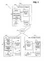
- FIG. 1depicts a data processing system 100 suitable for practicing methods and systems consistent with the present invention.
- Data processing system 100includes a group of computers 102 a , 104 , and 106 that are connected via a network 108 .
- Network 108may be any known physical or wireless network capable of supporting a data transmission between two computer systems, such as a Local Area Network (LAN), a Wide Area Network (WAN), the Internet, or leased phone lines.
- LANLocal Area Network
- WANWide Area Network
- the Internetor leased phone lines.
- computer 102 amay actually be one of multiple computers (i.e., computers 102 a and 102 n ) used by affiliates of an enterprise or business conglomerate to communicate with one another via network 108 .
- the enterprise affiliatesmay be employees, managers, administrators, suppliers, customers, other computer applications, other computer systems, or other users within the enterprise who may need to create, view, or receive information regarding an activated project plan in accordance with methods and systems consistent with the present invention.
- Each computer 102 a , 104 , and 106includes a memory ( 110 , 112 , and 114 , respectively), a secondary storage device ( 116 , 118 , and 120 , respectively), an I/O device ( 122 , 124 , and 126 , respectively), and a processor ( 128 , 130 , and 132 , respectively).
- Memory 110 in computer 102 aincludes a Client Interface 134 to a Web-based “Distributed Authoring and Versioning” (WebDAV) server 140 in memory 112 .
- Client Interface 134has Process and Plan modules 136 that collectively allow an enterprise affiliate to create a reusable workflow and to create and activate a project plan based on the reusable workflow.
- WebDAVWeb-based “Distributed Authoring and Versioning”
- Memory 110 in computer 102 aalso includes a target processor interpreter, such as a JavaTM Virtual Machine 138 .
- a target processor interpretersuch as a JavaTM Virtual Machine 138 .
- the Client Interface 134may be developed using the JavaTM Programming Language.
- Client Interface 134may include JavaTM bytecodes.
- the JavaTM Virtual Machine 138interprets the JavaTM bytecodes of the Client Interface 134 so that the Client Interface 134 may execute on computer 102 a.
- the WebDAV server 140 in memory 112 of computer 104operates as a virtual file system for computers 102 a , 102 n , and 106 on the network 108 .
- WebDAV Server 140communicates on the network 108 using the WebDAV protocol, and stores files on WebDAV storage 142 .
- WebDAV storage 142may be a known database, such as Oracle, DB2, MS Structured Query Language (SQL) storage, or any Java Database Connectivity (JDBC)-compliant database.
- WebDAV Server 140includes a database management system (DBMS) or a JDBC interface to control access to the WebDAV storage 142 .
- DBMSdatabase management system
- JDBCJava Database Connectivity
- two separate enterprise affiliates using their respective Client Interfaces 134 on their respective computers 102 a and 102 nmay independently request and view the same workflow or plan stored on WebDAV Storage 142 .
- the Client Interface 134allows any enterprise affiliate to create, delete, move, and copy workflows, project plans, and associated roles/resource lists on WebDAV server 140 .
- properties of a process, a plan, or a task of a planmay be added, located, or changed on WebDAV Storage 142 by Client Interface 134 using known methods of the WebDAV protocol.
- the WebDAV protocolis a set of known extensions to the standard HyperText Transfer protocol (HTTP) that allows enterprise affiliates using client computers 102 a and 102 n to collaboratively store, edit, and manage files remotely on a Web Server, such as WebDAV Server 140 using network 108 .
- HTTPdefines how messages sent to or from a Web server on the Internet are formatted and transmitted.
- HTTPalso defines what actions a Web server or Web browser of a computer on the Internet should take in response to various commands submitted as part of an HTTP message.
- the WebDAV protocoldefines a WebDAV resource to be a collection (e.g., a directory or folder on WebDAV Storage 142 ) or a collection member (e.g., a file or Web page on WebDAV Storage 142 ).
- Each WebDAV resourcehas a content file and properties associated with the content file. The properties include the creation date, the author, and the access rights for the WebDAV resource.
- the WebDAV protocolspecifies the methods to create, delete, move, and copy a WebDAV resource. It also specifies the methods to add, find, or change a property of a WebDAV resource.
- Memory 114 in computer 106includes a Tool Server 144 .
- the Tool Server 144includes a WebDAV proxy 146 and Management Modules 148 .
- WebDAV proxy 146mediates communication between the Client Interface 134 and the WebDAV server 140 .
- the messages or requests directed to the WebDAV server 140 from the Client Interface 134are initially sent to the WebDAV proxy 146 , as discussed in detail below.
- the WebDAV proxy 146passes these messages and requests to the Management Modules 148 .
- Each of the Management Modules 148is configured to inform the WebDAV proxy 146 when a message or request has been serviced.
- the WebDAV proxy 146sends the message or request to the WebDAV Server 140 via the network 108 . If, on the other hand, the Management Modules 148 are able to service the message or request, the message or request is not sent to the WebDAV Server 140 .
- the types of messages or requests serviced by the Management Modules 148include activating a project plan, notifying various enterprise affiliates assigned to each task of the plan, and managing the execution of the plan to the enterprise affiliates.
- memory 114 in computer 106includes a WebDAV servlet (not shown), which is an application designed to perform as a WebDAV Engine in lieu of WebDAV Server 140 .
- the WebDAV servletmay be started by and executed within the Tool Server 144 .
- WebDAV servletis persistent. Thus, once WebDAV servlet is started, it stays in memory and can fulfill multiple requests.
- WebDAV servletis configured to control access to WebDAV Storage 142 , which may be included in secondary storage 120 in computer 106 .
- Memory 114 in computer 106also includes a target processor interpreter, such as a JavaTM Virtual Machine 150 .
- a target processor interpretersuch as a JavaTM Virtual Machine 150 .
- the Tool Server 144includes JavaTM bytecodes that the Java Virtual Machine 150 interprets so that the Tool Server 144 may execute on computer 106 .
- the data processing system 100may operate in a local host configuration rather than across the network 108 .
- the memory 110 of computer 102 amay include the Tool Server 144 and the WebDAV Server 140 .
- the secondary storage device 116may include the WebDAV Storage 142 .
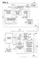
- FIG. 2depicts a functional architectural overview of the workflow modeling and project planning integration tool 200 used to integrate workflow modeling and project planning.
- the tool 200includes the Client Interface 134 as well as the Tool Server 144 .
- the Client Interface 134 and the Tool Server 144may be located on different computer systems, as discussed above.
- the Client Interface 134includes a Virtual File System (“VFS”) Interface 202 that is configured to allow the Client Interface 134 to connect to the secondary storage device 116 for local file access or to connect to the WebDAV Storage 142 via the WebDAV proxy 146 for virtual file access.
- VFSVirtual File System
- the VFS Interface 202is configured to send the virtual file access requests from the Client Interface 134 to a Uniform Resource Locator (URL) or network address for the WebDAV proxy 146 .
- URLUniform Resource Locator
- the URL for the WebDAV proxy 146may be “http://www.ToolServer.com/WebDAVproxy.”
- a URLtypically consists of an access protocol (e.g., http), a domain name (e.g., www.ToolServer.com), and, optionally, the path to a file or resource residing on that server (e.g., WebDAVproxy). If the Tool Server 144 , where the WebDAV proxy 146 is located, has an IP address of 192.168.5.1 and an assigned port address of 8088, then the URL for the WebDAV proxy translates to “http://192.168.5.1:8088/WebDAVproxy.”
- the VFS Interface 202initially sends the requests that the Client Interface 134 directs to the WebDAV Storage 142 to the WebDAV proxy 146 .
- the WebDAV proxy 146sends these requests to the Management Modules 148 .
- the WebDAV proxy 146sends the request to the WebDAV server 140 if the Management Modules 148 do not respond to the requests from the Client Interface 134 .
- the Tool Server 144directs the request to a URL or network address for the WebDAV server 140 .
- the Client Interface 134also includes a module loader 204 to load the Process and Plan modules 136 .
- Client Interface 134may be developed so that the functionality provided by Process and Plan modules 136 is not loaded by a known module loader 204 , but integrally incorporated within the element corresponding to the Client Interface 134 .
- the Process and Plan modules 136produce the requests to store or modify the various client files on the WebDAV storage 142 .
- the various types of client filesinclude a condition model, a user profile, a resource profile, a workflow definition file, and a plan definition file. Each of these files has properties defined in accordance with the WebDAV protocol.
- the various types of client filesfollow a schema or document type definition that is known to the Tool Server 144 so that the Tool Server 144 can identify the type of client file sent by the Client Interface 134 and intercepted by the WebDAV Proxy 146 .
- each type of client filehas a unique identifier, such as a URL network address, which the Tool Server 144 may use to locate the associated client file for processing.
- the various types of client filesare discussed in context with the general description of the Process and Plan modules 136 and also further discussed with the implementation details of creating a workflow and a project plan from the workflow.
- XML filesare used to represent the client files used with methods and systems consistent with the present invention, one skilled in the art will recognize that any file type can be used to represent the client files.
- the Process and Plan Modules 136include a Resource Manager Module 206 , an Activity I/O Condition Designer Module 208 , a Process Designer Module 210 , a Project Plan Manager Module 212 , and a Task Tracker Module 214 .
- the Resource Manager Module 206allows an enterprise affiliate with system administrative privileges or permissions, such as a project manager, to create, modify, and store a user profile for an enterprise affiliate.
- the user profileidentifies the access control rights that are associated with the enterprise affiliate, such as whether the enterprise affiliate may create or edit or delete a project plan based on a workflow or whether the enterprise affiliate is limited to viewing an existing workflow or plan.
- the Client Interface 134may specify that the user profile be stored with a unique identifier so that the Tool Server 144 may later locate the user profile for further processing. For example, the Client Interface 134 may request that the unique identifier be a location or URL where the user profile is to be stored on the WebDAV Storage 142 . If the unique identifier is stored as a property of the user profile on the WebDAV storage 142 , the Client Interface 134 sends a request to the WebDAV Server 140 to set the value of the property.
- the Resource Manager Module 206also allows an enterprise affiliate to create, modify, and store the role profiles that may be assigned to an activity of a workflow that is modeled using the tool 200 .
- the role profileidentifies a group of resources that may be assigned to complete a task created from the activity.
- the role profileis a type of client file that the Client Interface 134 may store on WebDAV storage 142 with a unique identifier (e.g., a URL for the role profile) to locate the role profile at a later time.
- a role profilemay include a Rolename that represents a “capability” or “skill set” for the role.
- an enterprise affiliatemay identify one of the following Rolenames to the Resource Manager Module 206 so that the associated role profiles are later available to assign when defining a software development process: Manager, Analyst, Software Architect, Software Developer, Tester, Hardware Architect, and Editor.
- the Resource Manager Module 206further allows an enterprise affiliate to create, modify, and store the resource profiles (e.g., the person, equipment, or systems, such as a development facility) that may be assigned to a task of a plan created from a workflow.
- the resource profileincludes a resource ID and a unique identifier for the role profile so that the Client Interface 134 may communicate to the Tool Server 144 that the identified resource has skills or capabilities corresponding to the role profile.
- the Tool Server 144may recognize that the person can play a given role (e.g., Analyst) in a specific activity (e.g., Requirements Analysis) in a workflow (e.g., Software Development Process) based on the skills or capabilities required by the role assigned to the activity to be performed.
- a given rolee.g., Analyst
- a specific activitye.g., Requirements Analysis
- a workflowe.g., Software Development Process
- the Activity I/O Condition Designer Module 208allows an enterprise affiliate, such as a manager, to define a condition model, i.e., an input condition or an output condition, for an activity of a workflow.
- the Activity I/O Condition Designer Module 208stores the condition model with a unique identifier so that the Tool Server 144 may later locate the condition model for processing, such as when a task of a plan is created from the activity of the workflow, as explained below.
- the Activity I/O Condition Designer Module 208allows the enterprise affiliate to create a condition model based on one of these two condition types.
- the Activity I/O Condition Designer Module 208also allows the enterprise affiliate to assign a document-type condition model or a logic-type condition model to an activity when creating the activity in a workflow.
- Each document-type and logic-type condition modelhas properties defined by the enterprise affiliate that created the respective condition model using the Activity I/O Condition Designer Module 208 .
- the properties of the document-type condition modelinclude a location property (e.g., a URL) identifying the location of the document or artifact being monitored.
- a location propertye.g., a URL
- the Client Interface 134uses the location property to notify the resource responsible for the task where to find the document or artifact so that the resource may complete its task.
- Another property of the document-type condition modelis a state property that indicates the allowable states of the document or artifact.
- the documentmay have the states “DRAFT” and “APPROVED.”
- the enterprise affiliateassigns one of these allowable states as a condition for entry into or exit from the activity (or the task created from the activity).
- the Workflow Engine 222evaluates whether the state property of the document condition satisfies the input or output condition of the activated task before starting or closing the task.
- Activity I/O Condition Designer Module 208allows the enterprise affiliate to define the properties shown in Table 1.
- the Client Interface 134uses the logic-type condition model to generate a logic-type condition for entry/exit and the script (e.g., logic element) to be performed to determine if the condition is met.
- the enterprise affiliatemay indicate to the Activity I/O Condition Designer Module 208 that the condition is to check if the task is complete and that the logic to be performed is to check the status property of the task. In this case, the user or resource assigned to this task must notify the Client Interface 134 that the task is complete.
- the enterprise affiliatemay indicate to the Activity I/O Condition Designer Module 208 that the condition is to check if the task is complete and that the logic to be performed is to check for the existence of a file in a specific directory folder on WebDAV Storage 142 in order to determine if the task is complete.
- the user or resource assigned to this taskmust create or move a file into the specific directory folder to indicate that the task is complete.
- the Process Designer Module 210allows an enterprise affiliate to create, modify, and store a workflow.
- Process Designer Module 210produces a workflow definition file based on the modeled workflow object.
- Client Interface 134then sends as the workflow definition file as a client file to WebDAV Server 140 to be stored on WebDAV Storage 142 .
- Each workflow definition file produced by Process Designer Module 210includes a unique identifier (e.g., a URL for the workflow definition file) so that Tool Server 144 may later locate the workflow definition file corresponding to the modeled workflow for further processing.
- Project Plan Manager Module 212allows an enterprise affiliate to create and activate a project plan from a workflow definition file. In general, upon request to create a project plan, Project Plan Manager Module 212 sends a query message to the WebDAV Server 140 for the workflow definition files contained in WebDAV Storage 142 . As further described below, Project Plan Manager Module 212 receives the workflow definition files, allows the enterprise affiliate to select one of the workflow definition files to create a project plan, and then produces a plan definition file based on the selected workflow definition file. When instructed to save the plan by the enterprise affiliate, Project Plan Manager Module 212 sends the plan definition file as a client file to WebDAV Server 140 to be stored on WebDAV Storage 142 . Each plan definition file produced by Process Designer Module 210 includes a unique identifier (e.g., a URL for the plan definition file) so that Tool Server 144 may later locate the workflow definition file corresponding to the modeled workflow for further processing.
- a unique identifiere.g., a URL for the plan definition file
- the Task Tracker Module 214allows an enterprise affiliate to view the tasks of an activated project plan that are assigned to a specific resource, to activate or start a task of the project plan (e.g., indicate actual start time to Client Interface 134 ), to open or check-out a document artifact needed to accomplish the task, to close or check-in the document artifact after accomplishing the task, and to indicate that the task is completed.
- the Tool Server 144includes a module loader 216 to load the Management Modules 148 . Similar to the Client Interface 134 , the Tool Server 144 may be developed so that the functionality provided by Management Modules 148 is not loaded by a known module loader 216 , but integrally incorporated within the element corresponding to the Tool Server 144 .
- Management Modules 148include a User Authorization Module 218 , a Resource/Role Management Module 220 , and a Workflow Engine 222 .
- the Workflow Engine 222includes a Project Plan Management Module 224 and a Project Task Management Module 226 .
- the User Authorization Module 218verifies that that the enterprise affiliate making the request has a user profile on the WebDAV Storage 142 with the proper authorization or permission to access the requested client file.
- the User Authorization Module 218may be connected to a Light Directory Access Protocol (LDAP) Import Module 228 , which follows a known LDAP protocol to allow the User Authorization Module 218 to obtain existing user profiles from another computer on network 108 .
- LDAPLight Directory Access Protocol
- an LDAP protocolis based on “entries,” where an entry is a collection of attributes that have a “distinguished name” (DN).
- directory entriesare arranged in a hierarchical tree-like structure that reflects political, geographic, and/or organizational boundaries. For example, entries representing countries may appear at the top of the tree. The entries below the countries may represent states or national organizations. Below the states or national organizations may be entries representing people (e.g., user profiles), organizational units, printers, documents, or any other accessible entity.
- Each level in the hierarchical tree-like structure for the directory entriesmay be identified by a known standardized keyword, such as “CN” for the common name of the entry (e.g., user profile), “L” for locality name, “ST” for state or province name, “O” for organization name, “OU” for organizational unit name, and “C” for country name.
- the LDAP Import Module 228uses a DN to refer to the entry unambiguously via a concatenation of the hierarchical tree-like structure. After user profiles are retrieved by the User Authorization Module 218 via the LDAP import module 228 , the user profiles may then be stored on the WebDAV Storage 142 by a request from the Client Interface 134 .
- the Resource/Role Management Module 220reviews requests from an enterprise affiliate to assign a resource to a plan (e.g., to assign a user to a task of the plan).
- the Resource/Role Management Module 220may check the resource profile corresponding to the assigned resource on the WebDAV Storage 142 to verify that the resource is not overloaded. For example, the Resource/Role Management Module 220 determines whether a resource is already assigned to another task in another plan during the same time frame, thus preventing it from being able to complete one of the tasks to which it is assigned.
- the Resource/Role Management Module 220may also be connected to the LDAP Import Module 228 to allow the Resource/Role Management Module 220 to obtain existing resource profiles from another computer on network 108 .
- the resource profilesmay also be stored on WebDAV Storage 142 by a request from Client Interface 134 .
- the Workflow Engine 222reviews requests to activate, deactivate, or update a plan. For example, a request to update a plan occurs if the enterprise affiliate who is an owner of a task indicates in its request that the task is complete. The Workflow Engine 222 also manages the execution of the activated plans.
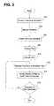
- FIG. 3depicts a flow diagram illustrating the high-level process performed by the workflow modeling and project planning integration tool in accordance with methods and systems consistent with the present invention.
- the toolcreates or retrieves a workflow (step 302 ).
- the tooldisplays the workflow (step 304 ).
- the workflowcomprises a set of activities that represents the steps to be performed as part of a plan executed from the workflow.
- Each activityhas an activity description and at least one role responsible for the activity.
- the activity descriptionindicates what step is to be performed by the role.
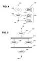
- FIG. 4depicts an exemplary document workflow 400 .
- the workflow 400includes a start element 402 , an end element 404 , and two activities, “Step 1 ” 406 and “Step 2 ” 408 .
- Step 1 ” 406occurs directly before “Step 2 ” 408 , “Step 1 ” 406 is the “predecessor activity” to “Step 2 ” 408 . Similarly, “Step 2 ” 408 is the “successor activity” to “Step 1 ” 406 .
- the workflow 400is used to monitor the state of Artifact 410 .
- the state of Artifact 410is “State 1 ” 412
- Step 2 ” 408the state of Artifact 410 is “State 2 ” 414
- the state of Artifact 410is “Complete” 416 .
- FIG. 5depicts an exemplary task workflow 500 .
- the task workflow 500includes a start element 502 , an end element 504 , two serial activities 506 and 508 and two parallel activities 510 and 512 .
- the workflowalso includes two synch bars 514 and 516 , which are used to connect the ends of parallel activities. Contrary to the document workflow, the task workflow allows for parallel activities.
- the workflow 600includes a start element 602 and an end element 604 .
- the first activity of the workflow 600is “Get Parts” 606 , which is followed by a logic activity, “L or Rt Handed?” 608 .
- Logic activitieshave two successor activities: a “default activity” and a “non-default activity.” As the name implies, the workflow generally follows the path of the default activity unless a condition is met in the logic activity, as discussed in detail below.
- the default activityis “Right” 610 .
- the non-default activityis “Left” 612 , which is followed by another activity “Left Special” 614 .
- the default pathis represented as a solid connector 616 while the non-default path is represented as a dotted connector 618 .
- any visible difference in the connectorse.g., a change in type, color, shading, labeling, etc., may be used to represent both the default path as well as the non-default path.
- Both the default activity 610 and the non-default activities 612 and 614are followed by another activity, “Complete Assembly” 620 .
- “Complete Assembly” 620In addition, though we show only two paths ( 616 & 618 ) out of the decision block 608 , there could be any number of exit paths (not shown).
- the next step performed by the toolis to create a plan from the workflow (step 306 ).
- Each activity in the default path of the workflowgenerally corresponds to a task in the plan.
- the taskidentifies the scheduled start and stop times for the task.
- the tooldisplays the plan (step 308 ).
- the plan created from the workflow 400 depicted in FIG. 4is shown in FIG. 7 .
- the plan 700includes two tasks 702 and 704 that correspond to the two activities 406 and 408 from the workflow 400 .
- the first task 702is scheduled to begin at 9 a.m. 706 on Aug. 1, 2001 (not shown), and end at 6 p.m. 708 on the same day.
- the second task 704is scheduled to begin at 9 a.m. 710 on Aug. 2, 2001 ( 712 ) and end at 5 p.m. 714 on the same day.
- the plan 800 created from the workflow 500 depicted in FIG. 5is shown in FIG. 8 .
- the plan 800includes two serial tasks 802 and 804 that correspond to the two serial activities 506 and 508 from the workflow 500 .
- the plan 800also includes two parallel tasks 806 and 808 that correspond to the two parallel activities 510 and 512 from the workflow 500 .
- “Serial 1 ” task 802is scheduled to begin at 9 a.m. 810 on Aug. 1, 2001 ( 812 ) and end at 5:30 p.m. 814 on the same day.
- the parallel tasks 806 and 808are scheduled to start at the completion of the “Serial 1 ” task 802 , and are scheduled to end at 6 p.m. 816 on Aug. 2, 2001 ( 818 ).
- the “Serial 2 ” task 804is scheduled to begin upon completion of the parallel tasks 806 and 808 and is scheduled to end at 6 p.m. 820 on Aug. 3, 2001 ( 822 ).
- the plan 900 created from the workflow 600 depicted in FIG. 6is shown in FIG. 9 .
- the plan 900includes a task 902 corresponding to the activity “Get Parts” 606 , followed by a task 904 corresponding to the activity “L or Rt Handed?” 608 .
- the following task 906corresponds to the activity “Right” 610 .
- the final task 908corresponds to the activity “Complete Assembly” 620 .
- the plan 900depicts the default path, and does not include any of the tasks corresponding to the non-default path.
- each taskhas a scheduled start and stop time.
- the tool 200requires that an enterprise affiliate assign a resource to each task, as described below.
- the toolthen activates the plan (step 310 ).
- the toolmanages the execution of the activated plan (step 312 ).
- the toolalso modifies the display of the plan as each task is executed (step 314 ).
- the tooldetermines whether the execution of the plan is complete (step 316 ). If the execution of the plan is complete, processing ends. Otherwise, processing continues to step 312 .
- the first task 702begins execution.
- the tooldepicts the executing task 1002 by darkening the outer borders of the block representing the task 1002 , as depicted in the plan 1000 shown in FIG. 10 .
- the tooldepicts the executed task 1102 as a darkened block in the plan 1100 , as shown in FIG. 11 .
- the second task 1104begins execution, as indicated by the darkened outer borders of the task 1104 .
- both tasks 1202 and 1204are depicted as darkened blocks in the plan 1200 , as shown in FIG. 12 .
- the toolrepresents an executing task with darkened borders and represents an executed task as a darkened block.
- any visible change in the blocks representing the taskse.g., a change in shape, color, shading, labeling, etc.
- colormay be used to indicate active tasks; for example a gray rectangle may be used behind the task to indicate an actual activity since the actual dates may not coincide with the dates of the planned task.
- the representation of the tasks used in the methods, systems, and articles of manufacture consistent with the present inventionare not limited to those used in the present embodiment.
- FIGS. 13-16depict the activation and execution of the tasks of the plan 800 depicted in FIG. 8 are shown in FIGS. 13-16 .
- FIG. 13depicts the state of the plan 1300 while the “Serial 1 ” task 1302 is executing.
- FIG. 14depicts the state of the plan 1400 after execution of the “Serial 1 ” task 1402 , while the “Parallel 1 ” and the “Parallel 2 ” tasks 1404 and 1406 are executing.
- FIG. 15depicts the state of the plan 1500 after execution of the “Serial 1 ” task 1502 and the “Parallel 1 ” and the “Parallel 2 ” tasks 1504 and 1506 , while the “Serial 2 ” task 1508 is executing.
- FIG. 16depicts the state of the plan 1600 after execution of the tasks 1602 , 1604 , 1606 , and 1608 .
- FIG. 9represents a plan 900 created from a workflow 600 having a logic block 608 .
- the activation and execution of the tasks of the plan 900 following the default pathare shown in FIGS. 17-21 , while the activation and execution of the tasks of the plan 900 following the non-default path are shown in FIGS. 22-27 .
- FIG. 17depicts the state of the plan 1700 while the “Get Parts” task 1702 is executing.
- FIG. 18depicts the state of the plan 1800 after the execution of the “Get Parts” task 1802 , while the “L Or Rt Handed?” logic task 1804 is executing.
- the logic taskmay pop up a dialog (not shown) to prompt the resource assigned to this task to provide an answer for this “left or right-handed” question.
- the toolallows the question to be “answered” by running a logic script. This script may examine properties of an indicated artifact or it may execute a separate program on a separate system to compute the answer.
- FIG. 19depicts both the “Get Parts” task 1902 and the “L Or Rt Handed?” logic task 1904 in executed states, while the “Right” task 1906 is depicted in an executing state.
- the state of the plan 2000is depicted in FIG. 20 with the “Get Parts” task 2002 , the “L Or Rt Handed?” logic task 2004 , and the “Right” task 2006 in executed states and with the “Complete Assembly” task 2008 in an executing state.
- the state of the plan 2100 after execution of the tasks 2102 , 2104 , 2106 , and 2108 is completeis depicted in FIG. 21 .
- the execution of the planis initially the same as when the default path is chosen.
- the plan 2200begins with the execution of the “Get Parts” task 2202 .
- the plan 2300 shown in FIG. 23depicts the “Get Parts” task 2302 in an executed state while the “L Or Rt Handed?” task 2304 is shown in an executing state.
- the resource assigned to choose the default or the non-default pathchooses the non-default path, thus completing the execution of the “L Or Rt Handed?” task 2404 , as indicated in FIG. 24 .
- the tool 200modifies the plan 2400 to correspond to the non-default path of the corresponding workflow.
- the plan 2400depicts the tasks included in the non-default path.
- the plan 2400includes the “Left” and “Left Special” tasks 2406 and 2408 rather than the “Right” task 2306 , which is depicted in FIG. 23 before the non-default path was chosen.
- the “Left” task 2406is executing.
- FIG. 25depicts the plan 2500 after the “Get Parts” task 2502 , the “L Or Rt Handed?” logic task 2504 , and the “Left” task 2506 have been executed, while the “Left Special” task 2508 is executing.
- FIG. 26depicts the state of the plan 2600 after the “Get Parts” task 2602 , the “L Or Rt Handed?” logic task 2604 , the “Left” task 2606 , and the “Left Special” task 2608 are done executing, while the “Complete Assembly” task 2610 is executing.
- FIG. 27depicts the state of the plan 2700 after completion of the tasks 2702 , 2704 , 2706 , 2708 , and 2710 .
- FIGS. 28A-Cdepict a flow diagram illustrating an exemplary process for retrieving or creating a workflow, i.e., step 302 in FIG. 3 .
- the tool 200determines whether to use an existing process or workflow group (step 2802 ).
- a workflow groupis a collection of workflows (e.g., a directory or folder containing the collection of workflows) created by the Client Interface 134 on WebDAV Storage 142 .
- Each workflow groupis created by the Client Interface 134 on WebDAV Storage 142 with the “workflow group” property as explained further below.
- the Client Interface 134allows the enterprise affiliate to store the workflow within an identified workflow group so that any enterprise affiliate using the Client Interface 134 is able to easily identify related workflows using a hierarchical relationship. For example, software-related workflows may be stored within the same workflow group so that an enterprise affiliate is able to quickly locate a desired workflow in order to create a corresponding plan using the Client Interface 134 .
- Client Interface 134may store a workflow on WebDAV Storage 142 without associating the workflow with a workflow group.
- the tool 200receives user input from an enterprise affiliate with system administrative privileges or permissions, such as a process designer or a project manager, to determine whether to retrieve an existing workflow group or to create a new workflow group. If the tool 200 determines that it will use an existing workflow group, the tool 200 receives an identification of the workflow group from the enterprise affiliate (step 2804 ). In one implementation, the Client Interface 134 may retrieve the identifications for the workflow groups on the WebDAV Storage 142 by requesting that the folders or directories on WebDAV Storage 142 having a “workflow” property be returned by the WebDAV Server 140 .
- the Client Interfacemay use any known method in accordance with WebDAV protocol to request that the WebDAV Server 140 return any directory or folder on WebDAV Storage 142 that corresponds to a workflow group.
- the tool 200may then display the available workflow groups to allow the enterprise affiliate to select one of the available workflow groups. For example, as shown on the user interface 2900 depicted in FIG. 29 , the tool 200 may display a hierarchical view 2902 of an identified workflow group 2904 stored on the root directory 2906 of WebDAV Storage 142 .
- the enterprise affiliatemay enter the identification of the desired workflow group to the tool 200 for retrieval. Using the identification, the tool 200 then retrieves the workflow group (step 2806 ).
- the tool 200receives the name of the workflow group from the enterprise affiliate (step 2808 ).
- the enterprise affiliatemay request a new workflow group by clicking on “Process Designer” button 2908 of the user interface 2900 depicted in FIG. 29 .
- the enterprise affiliatemay, alternatively, use any known data input technique, such as an icon or keyboard input, to indicate the request to the tool 200 .
- the tool 200displays an exemplary user interface 3000 depicted in FIG. 30 for receiving a new workflow group identification 3002 via keyboard input from an enterprise affiliate using computer 102 a or 102 n.
- the tool 200After receiving the new workflow group identification, the tool 200 creates a new workflow group in storage (step 2810 ). For example, the tool 200 may create the workflow group on WebDAV Storage 142 .
- the Client Interface 134sends the WebDAV Server 140 a request to create a new collection or folder on WebDAV Storage 142 with the same identification as the new workflow group identification 3002 .
- the Client Interface 134receives a response from the WebDAV Server 140 confirming that the new workflow group folder was created on WebDAV Storage 142 .
- the WebDAV properties(e.g., “date of creation,” “property name” and “lockdiscovery” properties) are created and stored in association with the new directory by the WebDAV Server 140 .
- the Client Interface 134when generating the new workflow group, the Client Interface 134 also sets the “property name” of the new workflow group to be “workflow group” so that the Client Interface may subsequently use known WebDAV methods, such as “PropFind,” to retrieve the identification of each workflow group on WebDAV Storage 142 .
- the tool 200determines whether to use an existing workflow (step 2812 ).
- the tool 200receives user input from an enterprise affiliate with appropriate privileges or permissions to determine whether to retrieve an existing workflow or to create a new workflow. If the tool 200 determines that it will use an existing workflow, the tool 200 receives an identification of the workflow from the enterprise affiliate (step 2814 ).
- the Client Interface 134may retrieve the identifications for the workflows in the selected workflow group and display the available workflows to allow the enterprise affiliate to select one of the available workflows. Alternatively, the enterprise affiliate may enter the identification of the desired workflow to the tool 200 for retrieval. Using the identification, the tool 200 then retrieves the workflow (step 2816 ).
- the tool 200receives the name of the workflow from the enterprise affiliate (step 2818 ).
- the enterprise affiliatemay request a new workflow by clicking on the desired workflow group 3102 and selecting the “New Process” option 3104 from a pull-down menu 3106 on the user interface 3100 depicted in FIG. 31 .
- the enterprise affiliatemay, alternatively, use any known data input technique, such as an icon or keyboard input, to indicate the request to the tool 200 .
- the tool 200may display the exemplary dialog box 3200 depicted in FIG. 32 to the enterprise affiliate.
- the enterprise affiliatemay then enter the name of a new workflow 3202 .
- the tool 200creates the workflow in storage (step 2820 ).
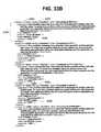
- FIGS. 33A-Cdepict an exemplary workflow definition file 3300 that is produced by the tool 200 when the workflow 600 depicted in FIG. 6 is created.
- the name 3302 of the workflow, “Logic Branch Project,”is identified in the workflow definition file 3300 .
- the workflow 600does not have a workflow group 3304 .
- the element 3306 in the workflow definition file 3300represents the “Get Parts” activity 606 .
- the element 3308FIG.
- the element 33Crepresents the “L or Rt Handed?” logic activity 608
- the element 3310represents the “Right” activity 610
- the element 3312represents the “Left” activity 612
- the element 3314represents the “Left Special” activity 614
- the element 3316represents the “Complete Assembly” activity 620 .
- the start element 602is represented by the element 3318
- the end element 604is represented by the element 3320 .
- the next step performed by the tool 200is to receive an indication of the type of activity to be created for the workflow (step 2822 in FIG. 28 B).
- the activitymay be a standard activity or a logic activity.
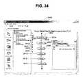
- the workflow 3402 depicted in the user interface 3400 of FIG. 34includes five standard activities 3404 , 3406 , 3408 , 3410 , and 3412 .
- the workflow 3402also includes one logic activity 3414 .
- the selection of the type of activitymay be made by clicking on the icon for a standard activity 3416 or the icon for the logic activity 3418 .
- any known data input techniquesuch as a pull-down menu or keyboard input, may be used to select the type of activity.
- the tool 200After receiving an indication of the type of activity, the tool 200 receives the name of the activity (step 2824 ).
- the names of the activities depicted in the workflow 3402are included with the activity.
- the name of activity 3404is “Assignment”
- the name of activity 3406is “Analysis,” etc.
- the name of the first activity 606is “Get Parts,” which is identified by the element 3322 in the workflow definition file 3300 of FIG. 33 .
- the name of the logic activity 608is “L or Rt Handed?,” which is identified by the element 3324 .
- the name of the activity 610is “Right,” as identified by the element 3326 .
- the name of the activity 612is “Left,” as identified by the element 3328 .
- the name of the activity 614is “Left Special,” as identified by the element 3330 .
- the name of the activity 620is “Complete Activity,” as identified by the element 3332 .
- the tool 200After receiving a name for the activity, the tool 200 receives an indication of the role responsible for the activity (step 2826 ).
- the Client Interfacevia Resource Manager Module 206 ) allows an enterprise affiliate to identify a role or role profile that may be assigned to an activity of the workflow.
- a role profileincludes a Rolename that represents a “capability” or “skill set,” which is needed to perform a task of a plan created from the workflow, where the task corresponds to the activity of the workflow.
- FIG. 35depicts a user interface 3500 displayed by the Client Interface to receive a role profile. In the implementation shown in FIG.
- the Client Interfacereceives a Rolename 3502 (e.g., “Project Manager”) for the role profile via the enterprise affiliate clicking on an “Add” button 3504 and then entering Rolename 3502 in a dialog box 3506 that is displayed by the Client Interface.
- a Rolename 3502e.g., “Project Manager”
- the Client Interfacemay also receive as additional entries (not shown) to dialog box 3506 a skill and an associated skill level for Rolename 3502 as part of this role profile.
- the enterprise affiliatemay indicate to the Client Interface via the additional entries to dialog box 3506 that the Rolename 3502 of “Project Manager” be associated with a skill entitled “Object-oriented software programming” and with a skill strength of “7” on a scale of 10.
- the enterprise affiliatemay assign to activities in the workflow the “Project Manager” role profile with this skill and skill level.
- the enterprise affiliatemay assign to activities in the workflow the “Project Manager” role profile with this skill and skill level.
- a resource having the appropriate skill and skill levelwill automatically be assigned by the Client Interface to tasks corresponding to the activities with the “Project Manager” role assignment.
- the tool 200stores the role profiles in association with the selected workflow activity on WebDAV Storage 142 .
- the tool 200saves significant costs in developing multiple workflows by allowing the enterprise affiliate to store the role profiles in association with the selected workflow activity on WebDAV Storage 142 so that the role profiles may be available for the enterprise affiliate to assign to an activity of another workflow that is also related to the selected workflow activity.
- the Client Interfacestores the role profiles in a single role definition file (not shown) on WebDAV Storage 142 .
- the Client Interfacestores the role profiles in separate files (not shown) on WebDAV Storage 142 . Each separate file has a name that is the same as the received Rolename 3502 .
- the Client Interfacedefines an associated WebDAV property having a common name, such as “role profile,” so that the Client Interface may later retrieve the role profiles stored on WebDAV storage.
- the role profilesmay also be stored with the workflow definition file. As shown in the workflow definition file 3300 depicted in FIG. 33 , the role profile 3334 for the “Get Parts” activity 606 indicates that the role responsible for the activity is “Assembler” 3336 . Similarly, the role profile 3338 for the “L or Rt Handed?” activity 608 indicates that the role responsible for the activity is “Assembler” 3340 . The role profile 3342 for the “Right” activity 610 indicates that the role responsible for the activity is “Assembler” 3344 . The role profile 3346 for the “Left” activity 612 indicates that the role responsible for the activity is “Assembler” 3348 .
- the role profile 3350 for the “Left Special” activity 614indicates that the role responsible for the activity is “Assembler” 3352 .
- the role profile 3354 for the “Complete Assembly” activity 620indicates that the role responsible for the activity is “Assembler” 3356 .
- the next step performed by the tool 200is to determine whether the activity has any predecessor activities (step 2828 ). If the activity does have a predecessor activity, the tool 200 receives an indication of the predecessor activities from the workflow definition file (step 2830 ). After checking for any predecessor activities and/or receiving the predecessor activities, the tool 200 determines whether the activity has any successor activities (step 2832 ). If the activity has a successor activity, the tool 200 receives an indication of the successor activities from the workflow definition file (step 2834 ). In the user interface 3400 of FIG. 34 , the “Path” icon 3420 is used to connect the predecessor activity to the successor activity.
- a path 3422was drawn from the “Assignment” activity 3404 to the “Analysis” activity 3406 .
- the “Assignment” activity 3404is the predecessor activity to the “Analysis” activity 3406
- the “Analysis” activity 3406is the successor activity to the “Assignment” activity 3404 .
- a “Vertical Fork/Join” icon 3424 or a “Horizontal Fork/Join” activitymay be used to connect more than one predecessor activities to a successor activity, or to connect a predecessor activity to more than one successor activities.
- the activity ID 3358 of the “Get Parts” activity 606is “10.”
- the predecessor 3360 to the “Get Parts” activity 606has an ID of “11” 3362 , which corresponds to the start element 602 .
- the successor 3364 to the “Get Parts” activity 606has an ID of “1522” 3366 , which corresponds to the “L or Rt Handed?” logic activity 608 .
- the predecessor 3368 to the “L or Rt Handed?” logic activity 608has an ID of “10” 3358 , which corresponds to the “Get Parts” activity 606 .
- the workflow definition file 3300identifies two paths out of the “L or Rt Handed?” logic activity 608 , one path 3370 has an ID of “1525” 3372 , which corresponds to the “Right” activity 610 , and the other path 3374 has an ID of “1523” 3376 , which corresponds to the “Left” activity 612 .
- the element representing the “L or Rt Handed?” logic activity 608also identifies that the default path 3378 has an ID of “1525” 3372 , which corresponds to the “Right” activity 610 .
- the predecessor 3380 to the “Right” activity 610 and the predecessor 3382 to the “Left” activity 612have an ID of “1522” 3366 , which corresponds to the “L or Rt Handed?” logic activity 608 .
- the remaining predecessor and successorsfollow this convention.
- an on-entry scriptis a step to be performed by the tool 200 upon entry into the activity.
- the on-entry scriptmay send an email notifying an interested user about the activity being started.
- the on-entry scriptmay also send a dialog box to an enterprise affiliate to obtain data in real-time, or send a request to a separate device to gather input, e.g., by sending a message to a computer to receive data files.
- Other examples of on-entry scriptsinclude checking stock levels and issuing reorder commands, if necessary, or paging the user assigned to perform the activity.
- the tool 200receives an indication of the on-entry scripts (step 2838 ). After checking for any on-entry scripts and/or receiving the on-entry scripts, the tool 200 determines whether the activity has any on-exit scripts (step 2840 in FIG. 28 C).
- An on-exit scriptis a step to be performed by the tool 200 upon exiting the activity. For example, the on-exit script may send an email notifying an interested user about the end of an activity.
- Other examples of on-exit scriptsinclude sending a message to another device to have the other device perform enterprise application integration, notifying a downstream consumer about the activity so that the consumer knows what is coming, and placing an activity on a user's personal calendar.
- the tool 200receives an indication of the on-exit scripts (step 2842 ).
- the “Complete Assembly” activity 620 depicted in FIG. 6includes both an on-entry script 3384 as well as an on-exit script 3386 .
- the tool 200Upon entering the task created from the “Complete Assembly” activity, the tool 200 sends an email to the owner indicating that the “Debugging period started” 3388 .
- the tool 200Prior to exiting the task created from the “Complete Assembly” activity, the tool 200 sends an email to the owner indicating that the “Debugging finished” 3390 .
- the tool 200determines whether the activity has any input (i.e., begin or starting) conditions (step 2844 ). If the activity has an input condition, the tool 200 receives an indication of the input conditions (step 2846 ). Example input conditions are to expect an artifact required for the task to have a specific status. After checking for any input conditions and/or receiving the input conditions, the tool 200 determines whether the activity has any output (i.e., exit or ending) conditions (step 2848 ). An example exit condition could be to automatically check the quality of an artifact generated by the task. If the artifact meets quality standards, the task completion occurs; otherwise, the task completion is rejected and the user is informed that more quality is required.
- An example exit conditioncould be to automatically check the quality of an artifact generated by the task. If the artifact meets quality standards, the task completion occurs; otherwise, the task completion is rejected and the user is informed that more quality is required.
- the tool 200receives an indication of the output conditions (step 2850 ).
- the output condition 3391 for the “Get Parts” activity 606has an ID of “1527” 3392 (FIG. 33 B), and is a document-type condition, as indicated by the “linkable 1 ” identity 3393 in the element 3394 representing the condition 3391 .
- the tool 200(in particular, the Workflow Engine 222 ) monitors the state of an artifact for an activated “Get Parts” task created from the “Get Parts” activity 606 until the state of the artifact is the “INITIAL” state 3395 before the tool 200 continues with the next task in the plan.
- the output condition 3396 for the “Right” activity 610has an ID of “1533” 3397 .
- the output condition 3396 for the “Right” activity 610is also a document-type condition, as indicated by the “linkable 1 ” identity 3398 . This condition 3396 signals the tool 200 to monitor the state of an artifact until it is in the “RIGHT” state 3399 .
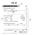
- FIG. 36depicts an exemplary user interface 3600 displayed by the Client Interface 134 to include either a document-oriented 3602 or a script (or logic)-oriented 3604 condition.
- the Client Interface 134may receive the request to add a condition to the activity via a pull-down menu selection 3606 .
- the enterprise affiliatemay, however, use any known data input technique to request that a condition be added to an activity, such as an icon or keyboard input, to indicate the request to the Client Interface 134 . If the enterprise affiliate selects a document-oriented condition, the enterprise affiliate may be presented with the user interface 3700 depicted in FIG. 37 to identify the properties of the condition to the Client Interface 134 .
- the condition properties 3702include condition-name property 3704 for the document-type condition model.
- the Client Interface 134receives the condition-name property 3704 via a keyboard input by the enterprise affiliate.
- the Client Interface 134uses the condition-name property 3704 to distinguish the condition model to be created from other condition models stored on WebDAV Storage 142 .
- the Client Interface 134may store the document-type condition model file on WebDAV Storage 142 having the same name as the condition-name property 3704 .
- the Client Interface 134may store the condition-name property 3704 as a WebDAV property stored in association with the document-type condition model file on WebDAV Storage 142 .
- the Client Interface 134also receives a link-parameter property 3706 as one of Condition properties 3702 for the document-type condition model to be created by the Client Interface.
- the enterprise affiliatemay identify link-parameter property 3706 to the Client Interface via keyboard input.
- Link-parameter property 3706may be used by an enterprise affiliate in an activity-related script that is identified to the Client Interface during the creation of a workflow as described below.
- the Workflow Engine 222 in FIG. 2is able to locate the corresponding document condition so that the corresponding input or output condition may be evaluated by the Workflow Engine 222 .
- the Client Interface 134may also receive a description property 3708 as one of Condition properties 3702 for the document-type condition model to be created by the Client Interface.
- the Client Interfacemay display description property 3708 in association with condition-name property 3704 to allow an enterprise affiliate to effectively choose whether the document-type condition model should be assigned to an activity of the workflow.
- the Client Interfacemay also receive one or more triggering-event properties 3710 for the document-type condition model.
- the Client Interfacemay receive the triggering-event properties as one of the condition properties 3702 for the document-type condition model to be created by the Client Interface.
- Triggering-event properties 3710indicate to the Workflow Engine 222 when to check the state property of a document condition as an entry or exit condition of an activated task.
- Triggering-event properties 3710may include a “Write into document” event 3712 , a “Change property of document” event 3714 , a “Put document into repository” event 3716 , a “copy or move into document” event 3718 , and a “delete document” event 3720 .
- the Client Interface 134receives document state properties 3722 as one of the Condition properties 3702 for the document-type condition model to be created by the Client Interface.
- Document state properties 3722identify possible values for a state property of a document condition that is created using the document-type condition model.
- an enterprise affiliatewho has been identified as the responsible owner of an activated task may change the state property of a document condition (e.g., from “DRAFT” to “APPROVED”) using the Client Interface, which sends a request to WebDAV Server 140 in FIG. 2 to set the state property of the document condition as indicated by the enterprise affiliate.
- Workflow Engine 222 in FIG. 2may then check the state property of the document condition on WebDAV Storage 142 when triggering-events 3710 occur.
- the Client Interfacealso receives a location property 3724 as one of Condition properties 3702 identified by the enterprise affiliate for the document-type condition model.
- Location property 3724is a unique identifier or URL for a document template that the Client Interface uses to create the document condition that is then stored by the Client Interface on WebDAV Storage 142 .
- Location property 3724may be a location on secondary storage device 116 of computer 102 a or a location on WebDAV Storage 142 .
- the document conditionis created by the Client Interface 134 when a plan is instantiated or created from a workflow having an activity with an entry or exit condition created using the document-type condition model.
- the Client Interfacereceives application property 3726 as one of Condition properties 3702 identified by the enterprise affiliate for the document-type condition model.
- Application property 3726is a unique identifier or URL for an application, such as Microsoft Word, that the Client Interface may run to create an instant of the document template that may be found at the location specified by location property 3724 .
- the Client Interfaceuses the instant of the document template to create and store the document condition on WebDAV Storage 142 .
- FIG. 38depicts an exemplary user interface 3800 displayed by the Client Interface 134 to receive the condition properties 3802 for a logic-type condition model that is to be created by the Client Interface 134 .
- the condition properties 3802include a condition-name property 3804 for the document-type condition model.
- the Client Interface 134receives the condition-name property 3804 via a keyboard input by the enterprise affiliate.
- the Client Interface 134uses the condition-name property 3804 to distinguish the logic-type condition model to be created from other condition models stored on WebDAV Storage 142 .
- the Client Interface 134stores a logic-type condition model file on WebDAV Storage 142 that has the same name as condition-name property 3804 .
- the Client Interface 134may also store condition-name property 3804 as a WebDAV property stored in association with the logic-type condition model file on WebDAV Storage 142 .
- the Client Interface 134may receive a description property 3806 as one of the Condition properties 3802 for the logic-type condition model to be created by the Client Interface 134 .
- the Client Interface 134may display the description property 3806 in association with the condition-name property 3804 to allow an enterprise affiliate to effectively choose whether the logic-type condition model should be assigned to an activity of the workflow.
- the Client Interface 134may also receive one or more triggering-event properties 3808 for the logic-type condition model as one of the condition properties 3802 for the logic-type condition model to be created by the Client Interface 134 .
- Triggering-event properties 3808indicate to the Workflow Engine 222 when to check an entry or exit condition of an activated task.
- Triggering-event properties 3808include: an “Absolute time” event 3810 , a “Period” event 3812 , a “URL change” event 3814 , a “Task change” event 3816 , and “any http request” event 3818 .
- “Absolute time” event 3810identifies a trigger for a specific data and time from the start time of the activated task.
- “Period” event 3812identifies a trigger for a specific unit of time, such as once every minute.
- URL change event 3814identifies a trigger when the contents of the directory or folder located at the URL changes.
- Tisk change” event 3816identifies a trigger for any time the activated task definition file or associated property changes.
- the Client Interface 134when an enterprise affiliate that is responsible for the task uses the Client Interface 134 to identify that the task is complete, the Client Interface 134 in response sends a request to the WebDAV Server 140 to set the status property of the activated task to “FINISHED.” As part of the processing for managing an activated plan as described below, the Workflow Engine 222 will receive this request before the WebDAV Server 140 and interpret the request as an example of a “Task change” event 3816 . Similarly, “Any http request” event 3818 indicates to the Workflow Engine 222 to check the entry or exit condition of the activated task when any request is received from the Client Interface 134 that pertains to the activated task.
- the Client Interface 134may send a request to the WebDAV Server 140 to retrieve the activated task file so that a status of the activated task can be viewed by an enterprise affiliate.
- Workflow Engine 222will receive this request before the WebDAV Server 140 and interpret the request as an example of an “Any http request” event 3818 .
- the Client Interface 134may also receive a script 3820 as one of the condition properties 3802 for the logic-type condition model to be created by the Client Interface 134 .
- Script 3820is executed by the Workflow Engine 222 when a triggering-event occurs that corresponds to one of the triggering-event properties 3808 selected by the enterprise user using the Client Interface 134 .
- Script 3820may include a script parameter 3822 , a script value 3824 for script parameter 3822 , and script content 3826 that may use the script parameter 3822 initialized to the script value 3824 .
- the enterprise affiliatemay provide the script content 3826 to the Client Interface 134 via a Script Editor User Interface 3900 in FIG. 39 .
- Script Editor User Interface 3900is displayed by the Client Interface 134 when the enterprise affiliate actuates button 3828 on user interface 3800 shown in FIG. 38 .
- Script content 3820may contain any known application program interface (API) script method that would be recognizable by the target processor interpreter on computer 106 , such as JavaTM Virtual Machine 150 in FIG. 1 .
- APIapplication program interface
- the tool 200determines whether there are any more activities to add to the workflow (step 2852 ). If there are more activities, the process continues at step 2822 for the next activity. If there are no more activities to add to the workflow, the tool 200 receives an indication of the starting point for the workflow (step 2854 ). Next, the tool 200 receives an indication of the ending point for the workflow (step 2856 ) before the process ends.
- FIG. 40depicts an exemplary user interface 4000 displayed by the Client Interface 134 to receive the properties of an activity of a workflow.
- the name 4002 of the activitye.g., “Specs Development”
- the duration 4004 of the activitye.g., 1 unit
- the role 4006 responsible for the activitymay be entered by the enterprise affiliate responsible for creating or modifying the workflow.
- the enterprise affiliatemay enter an on-entry script 4008 as well as an on-exit script 4010 .
- the properties of the activityalso include the location 4012 of the sub-process defining the workflow. This allows an enterprise to save significant resources by providing a mechanism for reusing workflows within other workflows.
- workflowsmay be modularly built from constituent workflows.
- the defect tracking workflow depicted in FIG. 34can be used inside many “outer” or “higher-level” processes for software development.
- FIGS. 41A-Bdepict a flow diagram illustrating the process of creating a plan from a workflow, i.e., step 306 in FIG. 3 .
- the enterprise affiliatehas already selected the workflow that will be used to create the plan.
- the tool 200receives an indication of the plan name (step 4102 ).
- the Client Interface 134allows the enterprise affiliate to store the project plan within an identified project plan group so that any enterprise affiliate using the Client Interface 134 is able to easily identify related project plans.
- a process plan groupis a collection of project plans (e.g., a directory or folder containing the collection of project plans) created by the Client Interface 134 on WebDAV Storage 142 .
- the software-related project plansmay be stored within the same project plan group so that an enterprise affiliate is able to quickly locate a desired project plan in order to create a corresponding plan using the Client Interface 134 .
- Client Interface 134may store a project plan on WebDAV Storage 142 without associating the project plan with a project plan group.
- FIG. 42depicts an exemplary user interface 4200 used to receive a project plan group.
- the Client Interface 134receives a dialog box 4202 to enter the name of a new project plan group 4204 (e.g., “Software Projects”) after clicking on a “Create Group” button 4206 .
- a new project plan group 4204e.g., “Software Projects”
- the tool 200provides the enterprise affiliate with a list 4300 of available project groups from which the enterprise affiliate may choose, as depicted in FIG. 43 .
- the tool 200then provides the enterprise affiliate with a dialog box 4400 to enter the name 4402 of the project, as shown in FIG. 44 .
- FIG. 45depicts an exemplary timetable 4500 which the enterprise affiliate may use to identify the timetable defining a workday. As shown, the enterprise affiliate may select a timetable template 4502 with predefined working hours.
- the Standard Timetable 4504includes five Working Days 4506 (Monday through Friday) and Working Hours 4508 from 8 a.m. ( 4510 ) through 12 p.m. ( 4512 ) and from 1 p.m. ( 4514 ) until 5 p.m. ( 4516 ).
- the enterprise affiliatemay select a 24 Hour Timetable 4518 or an Intensive Timetable 4520 , i.e., more than the Standard Timetable 4504 , but less than the 24 Hour Timetable 4518 .
- the tool 200also receives an indication of the start date and time for the project plan (step 4106 ).
- An exemplary dialog box 4600may be used to select the start date and time 4602 and end date and time 4604 .
- the tool 200then retrieves an activity from the workflow (step 4108 ).
- the tool 200sets the start time of the task equal to the start date and time of the project plan (step 4110 ).
- the tool 200sets the end time of the task based on the start time of the task, the duration of the activity from which the task is based, and on the working hours (step 4112 in FIG. 41 B).
- the tool 200then receives an indication of the resource assigned to the task (step 4114 ).
- FIG. 47depicts an exemplary workflow definition file 4700 that is produced by the tool 200 when the workflow 500 depicted in FIG. 5 is created.
- FIG. 48depicts an exemplary project plan definition file 4800 created from the workflow definition file 4700 .
- the element 4702 in the workflow definition file 4700represents the “Serial 1 ” activity 506 .
- the “Serial 1 ” activity 506has a duration 4704 of 9 hours. If the working hours are determined based on the “24 Hour Timetable” 4818 and the start date and time for the project plan is 9 a.m. on Aug. 1, 2001, the start time 4804 for the “Serial 1 ” task 4802 is 9 a.m. on Aug. 1, 2001. The end time 4806 of the task 4802 occurs 9 hours later, i.e., at 6 p.m. on Aug. 1, 2001.
- FIG. 49depicts an exemplary user interface 4900 displayed by the Client Interface 134 to assign users or resources to the project and to assign these users specific roles related to the roles required by the project.
- the tool 200displays a list of available users or resources 4902 (on the left), a list of the assigned users (central), and a list of the roles 4904 (on the right) in a given workflow.
- the enterprise affiliateis allowed to selectively add or remove available resources to the project by highlighting the resource and selecting either the “Add” button 4906 or the “Remove” button 4908 , respectively.
- the enterprise affiliatemay add or remove the resources to the project by selecting the “Add all” button 4910 or the “Remove all” 4912 button, respectively.
- the enterprise affiliatemay identify to the tool 200 resources that are capable of performing the role when assigned to a task in the plan.
- the tool 200may automatically assign a resource to a role of a task in the plan based on the identified, capable resources for the role.
- the properties of an activitymay be modified using the exemplary user interface 5000 depicted in FIG. 50 .
- the user interface 5000displays the name 5002 of the activity, the duration 5004 assigned to the corresponding activity, the start date and time 5006 for the activity, the end date and time 5008 for the activity, the responsible role 5010 assigned to the corresponding activity, the responsible resource or user 5012 assigned to the task, the owners 5014 of the task, the priority 5016 of the task, the on-entry script 5018 of the task, and the on-exit script 5020 of the task.
- the responsible resource 5012 of the taskis the resource with the authority to notify the tool 200 when the task is complete.
- the owner(s) 5014 of the taskare notified when the task is started or completed, but do not have the authority to modify the tool 200 when the task is complete.
- the next step performed by the tool 200is to determine whether there are any more activities in the workflow (step 4116 ). If there are no more activities, the process ends. If there are more activities, the tool 200 retrieves the next activity (step 4118 ). The tool 200 then sets the start time of the task equal to the end time of the predecessor task (step 4120 ). The process then continues at step 4112 .
- the next activities that are retrieved by the tool 200are “Parallel 1 ” 510 and “Parallel 2 ” 512 .
- Element 4706 and element 4708 in the workflow definition file 4700represent these activities 510 and 512 .
- the durations 4710 and 4712 of both of these activitiesis 24 hours.
- the start time 4812 and 4814 of these tasks 4808 and 4810is equal to the end time 4806 of the predecessor task, i.e., 6 p.m. on Aug. 1, 2001. Because the duration 4710 and 4712 of the activities 510 and 512 is 24 hours, the end times 4816 and 4818 of these tasks 4808 and 4810 occur 24 hours later, i.e., at 6 p.m. on Aug. 2, 2001.
- the next activity retrieved by the tool 200is “Serial 2 ” 508 .
- the element 4714 in the workflow definition file 4700represents this activity.
- the duration 4716 of the “Serial 2 ” activity 508is 24 hours.
- the start time 4822 of the task 4820 created from the “Serial 2 ” activity 508is the end time 4816 and 4818 of the predecessor task, i.e., 6 p.m. on Aug. 2, 2001. Because the duration 4716 of the “Serial 1 ” activity is 24 hours, the end time 4824 of the task 4820 is 6 p.m. on Aug. 3, 2001.
- the project planis displayed in the Gantt chart 5100 depicted in FIG. 51 .
- the “Serial 1 ” task 5102is scheduled to execute from 9 a.m. 5104 on Aug. 1, 2001 ( 5106 ) through 6 p.m. 5108 on the same day.
- the “Parallel 1 ” task 5110 and the “Parallel 2 ” task 5112are scheduled to execute from 6 p.m. 5108 on Aug. 1, 2001 ( 5106 ) through 6 p.m. 5114 on Aug. 2, 2001 ( 5116 ).
- the “Serial 1 ” task 5118is scheduled to execute from 6 p.m. 5114 on Aug. 2, 2001 ( 5116 ) through 6 p.m. 5120 on Aug. 3, 2001 ( 5122 ).
- an enterprise affiliate using the Client Interface 134 on the computer 102 amay create a plan from the workflow 600 at the same time that a second enterprise affiliate using the Client Interface 134 on computer 102 n creates a second plan from the workflow 600 .
- the planmay be activated.
- the enterprise affiliatemay activate the project by selecting the “Activate Project” option 5202 from the pull-down menu 5200 .
- the enterprise affiliatemay, however, use any known data input technique, such as an icon or keyboard input, to indicate the request to Client Interface 134 .
- the Client Interface 134then sends an activate request to the WebDAV server 140 to change the status of the plan definition file to “Active.”
- the Workflow Engine 222may intercept this request and process the request in preparation for managing the execution of the activated plan.
- any enterprise affiliate with appropriate privilegese.g., project manager that “owns” the plan
- FIG. 53depicts a flow diagram illustrating an exemplary process performed by the Client Interface 134 to add a new resource to the list of available resources.
- the Client Interface 134may later assign the resource to a plan in accordance with methods and systems consistent with the present invention.
- the Client Interface 134receives a request to add a new resource (step 5302 ).
- the Client Interface 134may receive the request to add a new resource via a pull-down menu selection 5402 and 5404 that is chosen by an enterprise affiliate.
- the enterprise affiliatemay, however, use any known data input technique, such as an icon or keyboard input, to indicate the request to the Client Interface 134 .
- the Client Interface 134determines whether the request is to import the resource information (step 5304 ).
- an enterprise affiliaterequests that the Client Interface 134 import a resource profile containing the resource information by choosing the pull-down menu selection 5404 .
- the enterprise affiliatemay request that the Client Interface 134 create the resource profile from resource information that the enterprise affiliate provides to the Client Interface 134 .
- the Client Interface 134receives the resource information from the enterprise affiliate (step 5306 ). As shown in FIG.
- the Client Interface 134may receive resource information 5404 for an enterprise affiliate (e.g., a user or person) that may later be assigned to a plan by the Client Interface 134 in accordance with processes described in greater detail below.
- the Resource Information 5404may include a login name 5408 , a resource name 5410 that the Client Interface 134 is to use when assigning the resource to a task of a plan, and an e-mail address 5412 that the Client Interface 134 or the Workflow Engine 222 may use to notify the resource of an assignment or another event.
- the Client Interface 134may also receive other resource information (not shown) for other types of resources (e.g., equipment, facilities, computer systems, or other known entities) that may be assigned to any task of a plan.
- the other resource informationmay include: a resource name that the Client Interface 134 is to use when assigning the resource to a task of a plan; a resource owner name that identifies a manager or other enterprise affiliate who is responsible for the named resource; and an e-mail address for the named resource owner, which the Client Interface 134 or the Workflow Engine 222 may notify when the named resource is assigned to a task or for another associated event.
- Resource information 5404may also include one or more skill identifiers that indicate one or more capabilities that a task of a plan may require for the task to be completed. Skill identifiers may include any foreseeable skill for the named resource, including a user, equipment, facilities, computer systems, or other known entities that may be assigned to any task of a plan.
- the skill identifiers that may be identified for the enterprise affiliatemay include: “Java programming,” “architecture,” or “carpentry.”
- the skill identifiersmay include “punch-press,” “printing,” or “Windows NT Operating System.”
- Resource information 5404may also include a skill strength (not shown) for each skill identifier. The skill strength may be used by the tool to differentiate one resource from another resource when matching a resource to a role of a task in a plan.
- Resource information 5404may also include an availability timetable (not shown) that indicates to the Client Interface 134 the calendar days, the hours in a weekday, and the hours in a weekend day that the named resource is available to work. Resource information 5404 may also include an assignment timetable (not shown) that has assigned calendar days. The assigned calendar days indicate to the Client Interface 134 which calendar days the named resource has been assigned to one or more tasks. In addition, the assignment timetable may include unique identifiers or URLs for the one or more tasks to which the named resource has been assigned. Thus, the Client Interface 134 or the Workflow Engine 222 may access the one or more tasks that the named resource has been assigned when performing processing for resource leveling of a plan in accordance with methods and systems consistent with the present invention.
- the Client Interface 134receives access information for a “Lightweight Directory Access Protocol (LDAP)” resource directory entry (e.g., a resource profile) on the network 108 of FIG. 1 (step 5308 ).
- FIG. 55depicts an exemplary user interface 5500 showing access information 5502 received by the Client Interface 134 .
- Access information 5502includes an LDAP Server 5504 (e.g., “Frodo”) on the network 108 , an LDAP Port 5506 for the Client Interface 134 to communicate with the LDAP Server 5504 , and a resource distinguished name (DN) 5508 identifying the location on LDAP Server 5504 where the resource profile may be found.
- LDAP Server 5504e.g., “Frodo”
- DNresource distinguished name
- the access information 5502may be default access information that the Client Interface 134 retrieves from a configuration file (not shown) on the computer 102 a , or it may be access information entered by an enterprise affiliate.
- the access information 5502may also include: a security distinguished name (DN) 5510 , a password 5512 , and a login alias 5514 .
- Security DN 5510identifies to the Client Interface 134 where a security profile for the enterprise affiliate is located.
- the Client Interface 134uses the password 5512 and the login alias 5514 to access the resource information on the LDAP Server 5504 in accordance with privileges identified in the security profile.
- the Client Interface 134retrieves the resource information using the LDAP access information (step 5310 ).
- the resource information that the Client Interface 134 retrievesincludes resource profiles for a user, equipment, facilities, computer systems, or other known entities that may be assigned to any task of a plan.
- the Client Interface 134stores the resource information in resource profiles on the WebDAV Storage 142 (step 5312 ).
- FIG. 56depicts an exemplary resource file 5600 that the Client Interface 134 may use to store resource profiles 5602 , 5604 , 5606 , and 5608 on WebDAV Storage 142 .
- the resource profile 5600includes a unique identifier or URL 5612 where the resource profile 5600 is to be stored on the WebDAV Storage 142 .
- Each resource profile 5602 , 5604 , 5606 , and 5608may be stored separately by the Client Interface 134 on WebDAV Storage 142 .
- the resource profile 5602includes resource information 5610 that corresponds to an enterprise affiliate that may be assigned to a task of a plan.
- the resource information 5610may be added as properties rather than as the content of the resource profile 5602 on WebDAV Storage 142 .
- This implementationmay be advantageous as the Client Interface 134 or the Workflow Engine 222 may use a known WebDAV method to retrieve resource profiles from the WebDAV Storage 142 that have the same property.
- the WebDAV “PropFind” methodmay be used by the Client Interface 134 or the Workflow Engine 222 to retrieve the resource profiles having a skill identifier of “Java Programming” so that an available resource having this skill can be assigned to a task in accordance with processes described below.
- FIG. 57depicts a flow diagram illustrating an exemplary process performed by the Workflow Engine 222 to manage the execution of an activated plan.
- the Workflow Engine 222may execute the process in FIG. 57 for each activated plan stored on WebDAV Storage 142 .
- the toolmanages the execution of multiple plans simultaneously.
- the tool 200waits until the current time and date are later than the start time and date (step 5702 ) of the plan.
- a planmay not require a start time and date for each plan. Rather, the start time and date may be incorporated as an input condition for each task.
- the tool 200selects the current next task (or tasks in the event of parallel tasks) from the activated project plan created from a workflow (step 5704 ).
- the Workflow Engine 222may retrieve the plan from WebDAV storage.
- the tool 200determines whether there is an input condition (step 5706 ).
- the tool 200waits to see if the triggering event (described above) is met before it checks to see if the input condition is met (step 5708 ). If the input condition required monitoring of certain items on a periodic basis, the Workflow Engine 222 will add this event to its “Event Monitoring” log. After the input condition is met or if there is no input condition, the tool 200 stores the actual start time (step 5710 ). The next step performed by the tool 200 is to determine whether there is an on-entry script to execute, such as a message to send to the resource (step 5712 in FIG. 57 B). If there is an on-entry script, the tool 200 performs the on-entry script (step 5714 ).
- the tool 200determines whether there is an output condition (step 5716 ). If there is an output condition, the tool 200 waits to see if the triggering event (described above) is met before it checks to see if the output condition is met (step 5718 ). After the output condition is met or if there is no output condition, the tool 200 determines whether there is an on-exit script (step 5720 ). If there is an on-exit script, the tool 200 performs the on-exit script (step 5722 ). After performing the on-exit script or if there is no on-exit script, the tool 200 stores the actual end time (step 5724 ). Then the tool 200 determines whether there are any more tasks in the project plan (step 5726 ). If there are no more tasks, the process ends. Otherwise, the process returns to step 5704 and selects the next task.
- FIG. 58The plan 5800 created from the workflow 500 depicted in FIG. 5 is shown in FIG. 58 .
- “Serial 1 ” task 5802is scheduled to begin at 9 a.m. 5804 on Aug. 1, 2001 ( 5806 ) and end at 6 p.m. 5808 on the same day.
- the parallel tasks 5810 and 5812are scheduled to start at the completion of the “Serial 1 ” task 5808 , and are scheduled to end at 6 p.m. 5814 on Aug. 2, 2001 ( 5816 ).
- the “Serial 2 ” task 5818is scheduled to begin upon completion of the parallel tasks 5814 and is scheduled to end at 6 p.m. 5820 on Aug. 3, 2001 ( 5822 ).
- FIG. 59depicts an exemplary project plan definition file 5900 corresponding to the plan 5800 of FIG. 58 .
- the “Serial 1 ” task 6002begins execution, as depicted by the task 6004 in the Gantt chart 6000 of FIG. 60 . Contrary to the plan, however, the “Serial 1 ” task ends earlier than planned. As depicted in FIG. 61 , the actual properties 6100 of the “Serial 1 ” task 6102 include the actual-start-date 6104 (i.e., year-2001 month-8 day-1 hour-9) and actual-finish-date 6106 (i.e., year-2001 month-8 day-1 hour-14, i.e., 2 p.m.). The actual execution 6204 of the “Serial 1 ” task 6202 is shown in the Gantt chart 6200 of FIG. 62 .
- both the “Parallel 1 ” task 6206 and the “Parallel 2 ” task 6208begin execution at 2 p.m. 6210 rather than waiting until their scheduled start time of 6 p.m.
- the earlier execution 6212 and 6214 of these tasks 6206 and 6208is also depicted in the Gantt chart 6200 .
- the actual properties 6300 of the “Parallel 1 ” task 6302 and the “Parallel 2 ” task 6304include the actual-start-date 6306 (i.e., year-2001 month-8 day-1 hour-14) and actual-finish-date 6308 (i.e., year-2001 month-8 day-2 hour-0).
- the actual execution 6406 and 6408 of the “Parallel 1 ” task 6402 and the “Parallel 2 ” task 6404is shown in the Gantt chart 6400 of FIG. 64 .
- the Gantt chart 6400also visually indicates that the start time 6410 for the tasks 6402 and 6404 was 2 p.m. on Aug. 1, 2001, while the end time 6412 for the tasks 6402 and 6404 was 12 a.m. on Aug. 2, 2001.
- the execution of the “Serial 2 ” task 6414begins at 12 a.m. on Aug. 2, 2001 ( 6412 ).
- the actual properties 6500 of the “Serial 2 ” task 6502includes the actual-start-date 6504 (i.e., year-2001 month-8 day-2 hour-0) and actual-finish-date 6506 (i.e., year-2001 month-8 day-2 hour-12).
- the actual execution 6604 of the “Serial 1 ” task 6602 , the actual execution 6608 of the “Parallel 1 ” task 6606 , the actual execution 6612 of the “Parallel 2 ” task 6610 , and the actual execution 6616 of the “Serial 2 ” task 6614 ,are shown in the Gantt chart 6600 of FIG. 66 .
Landscapes
- Business, Economics & Management (AREA)
- Human Resources & Organizations (AREA)
- Engineering & Computer Science (AREA)
- Strategic Management (AREA)
- Economics (AREA)
- Entrepreneurship & Innovation (AREA)
- Physics & Mathematics (AREA)
- Theoretical Computer Science (AREA)
- General Physics & Mathematics (AREA)
- Marketing (AREA)
- General Business, Economics & Management (AREA)
- Development Economics (AREA)
- Operations Research (AREA)
- Tourism & Hospitality (AREA)
- Quality & Reliability (AREA)
- Game Theory and Decision Science (AREA)
- Educational Administration (AREA)
- Accounting & Taxation (AREA)
- Finance (AREA)
- Data Mining & Analysis (AREA)
- Management, Administration, Business Operations System, And Electronic Commerce (AREA)
Abstract
Description
| TABLE 1 | |||
| Property | Description | ||
| Name | The name used to identify the condition. | ||
| Description | A description of the condition. | ||
| When to | This section identifies when and/or how | ||
| Check | often the condition should be checked. | ||
| Abs. Time | The condition is checked when this | ||
| absolute time (calendar time) arrives. | |||
| Period | Integer expression in Javascript that | ||
| defines the periodicity of condition check, | |||
| where a “1” means once a minute. (If | |||
| absolute time is also specified, then the | |||
| condition should be checked when the | |||
| absolute time arrives and periodically | |||
| thereafter.) | |||
| URL | The condition is checked after URL | ||
| Change | undergoes a property or content change. | ||
| Task | The condition is checked when the task | ||
| Change | that is specified during plan creation | ||
| changes its state (e.g., starts, finishes). | |||
| Any | The condition is checked when any HTTP | ||
| Request | request is detected. | ||
| Script | The script to run when the condition is | ||
| met. The script must return “true” or | |||
| “false” (a Boolean). Script is an | |||
| extensible method for users to enter in ad | |||
| hoc logic. | |||
Claims (64)
Priority Applications (5)
| Application Number | Priority Date | Filing Date | Title |
|---|---|---|---|
| US09/944,697US6968343B2 (en) | 2000-09-01 | 2001-08-31 | Methods and systems for integrating process modeling and project planning |
| US10/165,405US20020188597A1 (en) | 2000-09-01 | 2002-06-07 | Methods and systems for linking tasks to workflow |
| PCT/US2002/017888WO2002103602A1 (en) | 2001-06-07 | 2002-06-07 | Methods and systems for linking tasks to workflow |
| US10/165,530US7096222B2 (en) | 2000-09-01 | 2002-06-07 | Methods and systems for auto-instantiation of storage hierarchy for project plan |
| PCT/US2002/018238WO2002099637A1 (en) | 2001-06-07 | 2002-06-07 | Methods and systems for auto-instantiation of storage hierarchy for project plan |
Applications Claiming Priority (3)
| Application Number | Priority Date | Filing Date | Title |
|---|---|---|---|
| US23005400P | 2000-09-01 | 2000-09-01 | |
| US29670701P | 2001-06-07 | 2001-06-07 | |
| US09/944,697US6968343B2 (en) | 2000-09-01 | 2001-08-31 | Methods and systems for integrating process modeling and project planning |
Related Child Applications (2)
| Application Number | Title | Priority Date | Filing Date |
|---|---|---|---|
| US10/165,530Continuation-In-PartUS7096222B2 (en) | 2000-09-01 | 2002-06-07 | Methods and systems for auto-instantiation of storage hierarchy for project plan |
| US10/165,405Continuation-In-PartUS20020188597A1 (en) | 2000-09-01 | 2002-06-07 | Methods and systems for linking tasks to workflow |
Publications (2)
| Publication Number | Publication Date |
|---|---|
| US20020077842A1 US20020077842A1 (en) | 2002-06-20 |
| US6968343B2true US6968343B2 (en) | 2005-11-22 |
Family
ID=26923866
Family Applications (5)
| Application Number | Title | Priority Date | Filing Date |
|---|---|---|---|
| US09/944,697Expired - Fee RelatedUS6968343B2 (en) | 2000-09-01 | 2001-08-31 | Methods and systems for integrating process modeling and project planning |
| US09/944,696AbandonedUS20020075293A1 (en) | 2000-09-01 | 2001-08-31 | Methods and systems for animating a workflow and a project plan |
| US09/944,847AbandonedUS20020107914A1 (en) | 2000-09-01 | 2001-08-31 | Methods and systems for optimizing resource allocation based on data mined from plans created from a workflow |
| US09/945,081Expired - Fee RelatedUS6938240B2 (en) | 2000-09-01 | 2001-08-31 | Methods and systems for improving a workflow based on data mined from plans created from the workflow |
| US11/032,968Expired - Fee RelatedUS7493591B2 (en) | 2000-09-01 | 2005-01-11 | Methods and systems for animating a workflow and a project plan |
Family Applications After (4)
| Application Number | Title | Priority Date | Filing Date |
|---|---|---|---|
| US09/944,696AbandonedUS20020075293A1 (en) | 2000-09-01 | 2001-08-31 | Methods and systems for animating a workflow and a project plan |
| US09/944,847AbandonedUS20020107914A1 (en) | 2000-09-01 | 2001-08-31 | Methods and systems for optimizing resource allocation based on data mined from plans created from a workflow |
| US09/945,081Expired - Fee RelatedUS6938240B2 (en) | 2000-09-01 | 2001-08-31 | Methods and systems for improving a workflow based on data mined from plans created from the workflow |
| US11/032,968Expired - Fee RelatedUS7493591B2 (en) | 2000-09-01 | 2005-01-11 | Methods and systems for animating a workflow and a project plan |
Country Status (3)
| Country | Link |
|---|---|
| US (5) | US6968343B2 (en) |
| AU (4) | AU2001286982A1 (en) |
| WO (4) | WO2002019224A1 (en) |
Cited By (67)
| Publication number | Priority date | Publication date | Assignee | Title |
|---|---|---|---|---|
| US20020170032A1 (en)* | 2001-03-14 | 2002-11-14 | International Business Machines Corporation | Method, system and computer program for deriving and applying quality of service specifications in a component-based development environment |
| US20030126004A1 (en)* | 2001-12-27 | 2003-07-03 | International Business Machines Corporation | Method and system for a graphical view of selectable work items |
| US20030233374A1 (en)* | 2002-03-14 | 2003-12-18 | Ulrich Spinola | Dynamic workflow process |
| US20030236692A1 (en)* | 2002-05-29 | 2003-12-25 | Martin Hertel-Szabadi | Project workforce management |
| US20040017400A1 (en)* | 2002-07-26 | 2004-01-29 | Ly Eric Thichvi | Method for project planning |
| US20040030992A1 (en)* | 2002-08-06 | 2004-02-12 | Trandafir Moisa | System and method for management of a virtual enterprise |
| US20040037412A1 (en)* | 2000-12-26 | 2004-02-26 | Herve Le Corre | Real-time data management for a network comprising a heterogeneous set of terminals, server and main terminal for such a system |
| US20040215747A1 (en)* | 2003-04-11 | 2004-10-28 | Jonathan Maron | System and method for a configuration repository |
| US20050049982A1 (en)* | 2003-02-24 | 2005-03-03 | Gopinath Ganapathy | Systems and methods for managing distributed design chains |
| US20050050513A1 (en)* | 2003-08-28 | 2005-03-03 | Tetsuro Motoyama | Data structure used for directory structure navigation in a skeleton code creation tool |
| US20050071801A1 (en)* | 2003-09-30 | 2005-03-31 | Stefan Jesse | API derivation and XML schema derivation for developing applications |
| US20050071803A1 (en)* | 2003-09-30 | 2005-03-31 | Markus Cherdron | Development environment for developing applications using a metamodel |
| US20050131750A1 (en)* | 2003-12-12 | 2005-06-16 | International Business Machines Corporation | Method for tracking the status of a workflow using weblogs |
| US20050132048A1 (en)* | 2003-12-12 | 2005-06-16 | International Business Machines Corporation | Role-based views access to a workflow weblog |
| US20050144308A1 (en)* | 2003-12-24 | 2005-06-30 | Ichiro Harashima | Method for managing file transfer actions, method for visualizing file transfer actions, and apparatus for managing file transfer actions and user terminals in file transfer system |
| US20050198021A1 (en)* | 2003-12-12 | 2005-09-08 | International Business Machines Corporation | Visualization of attributes of workflow weblogs |
| US20060004749A1 (en)* | 2004-05-28 | 2006-01-05 | International Business Machines Corporation | Method and system for managing execution of data driven workflows |
| US20060015478A1 (en)* | 2004-07-19 | 2006-01-19 | Joerg Beringer | Context and action-based application design |
| US20060143611A1 (en)* | 2004-12-28 | 2006-06-29 | Wasim Sadiq | Distribution of integrated business process models |
| US20060139352A1 (en)* | 2004-12-28 | 2006-06-29 | Fujitsu Limited | Computer product, operation-analysis support device, and operation-analysis support method |
| US20060143057A1 (en)* | 2004-12-28 | 2006-06-29 | Wasim Sadiq | Integration of distributed business process models |
| US20070088589A1 (en)* | 2005-10-17 | 2007-04-19 | International Business Machines Corporation | Method and system for assessing automation package readiness and and effort for completion |
| US20070179965A1 (en)* | 2006-01-27 | 2007-08-02 | Hogue Andrew W | Designating data objects for analysis |
| US20070179952A1 (en)* | 2006-01-27 | 2007-08-02 | Google Inc. | Displaying facts on a linear graph |
| US20070185870A1 (en)* | 2006-01-27 | 2007-08-09 | Hogue Andrew W | Data object visualization using graphs |
| US20070185895A1 (en)* | 2006-01-27 | 2007-08-09 | Hogue Andrew W | Data object visualization using maps |
| US20070198558A1 (en)* | 2005-08-26 | 2007-08-23 | Wen-Hsien Chen | Method and system of intelligent work management |
| US20070220483A1 (en)* | 2003-08-28 | 2007-09-20 | Tetsuro Motoyama | Approach for automatically generating program code |
| US20070226066A1 (en)* | 2001-08-31 | 2007-09-27 | Stephan Brunner | Configurator using structure and rules to provide a user interface |
| US20070288292A1 (en)* | 2000-10-24 | 2007-12-13 | Gauger Derek K | Network based, interactive project management apparatus and method |
| US20070288290A1 (en)* | 2006-06-07 | 2007-12-13 | Tetsuro Motoyama | Use of a database in a network-based project schedule management system |
| US20080015918A1 (en)* | 2006-07-14 | 2008-01-17 | Pangrazio Donald M | Workflow selection process and system |
| US20080077466A1 (en)* | 2006-09-26 | 2008-03-27 | Garrett Andrew J | System and method of providing snapshot to support approval of workflow changes |
| US20080082578A1 (en)* | 2006-09-29 | 2008-04-03 | Andrew Hogue | Displaying search results on a one or two dimensional graph |
| US20080109268A1 (en)* | 2006-11-03 | 2008-05-08 | At&T Knowledge Ventures, L.P. | Method and apparatus for examining workflow processes |
| US20080109291A1 (en)* | 2006-11-07 | 2008-05-08 | Montes De Oca Group, Inc. | Executing and Tracking Strategic Plans |
| US20080115195A1 (en)* | 2006-11-13 | 2008-05-15 | Microsoft Corporation | Remote workflow schedule authoring |
| US7386797B1 (en)* | 2002-05-22 | 2008-06-10 | Oracle Corporation | Framework to model and execute business processes within a collaborative environment |
| US7406432B1 (en)* | 2001-06-13 | 2008-07-29 | Ricoh Company, Ltd. | Project management over a network with automated task schedule update |
| US20080288320A1 (en)* | 2007-05-17 | 2008-11-20 | Ockers Jay R | Actionable business plan creation and execution |
| US20090083829A1 (en)* | 2007-09-20 | 2009-03-26 | C & S Operations, Inc. | Computer system |
| US20090099896A1 (en)* | 2007-10-15 | 2009-04-16 | International Business Machines Corporation | System and method for workflow delinquency remediation |
| US20090259682A1 (en)* | 2008-04-10 | 2009-10-15 | Baldwin Ronald B | Method for identifying requirements for designing information technology systems |
| US7640548B1 (en)* | 2002-06-21 | 2009-12-29 | Siebel Systems, Inc. | Task based user interface |
| US20100017246A1 (en)* | 2008-07-20 | 2010-01-21 | Farrell Glenn H | Software user interface for specification of project task dependencies and deadlines |
| US20100082498A1 (en)* | 2008-09-24 | 2010-04-01 | Savvion, Inc. | Computer software |
| US20100088139A1 (en)* | 2008-10-07 | 2010-04-08 | Rahi M Ahsan | Project management system adapted for planning and managing projects |
| US20100185547A1 (en)* | 2009-01-16 | 2010-07-22 | Scholar David A | Project planning system |
| US7953720B1 (en) | 2005-03-31 | 2011-05-31 | Google Inc. | Selecting the best answer to a fact query from among a set of potential answers |
| WO2011085203A1 (en)* | 2010-01-08 | 2011-07-14 | Fluor Technologies Corporation | Systems for estimating new industrial plant operational readiness costs |
| US20110209070A1 (en)* | 2007-07-26 | 2011-08-25 | Ryma Technology Solutions | Collaborative development method and system |
| US8055674B2 (en) | 2006-02-17 | 2011-11-08 | Google Inc. | Annotation framework |
| US8065290B2 (en) | 2005-03-31 | 2011-11-22 | Google Inc. | User interface for facts query engine with snippets from information sources that include query terms and answer terms |
| US20120179504A1 (en)* | 2009-10-07 | 2012-07-12 | Hirofumi Nakashima | P2p workflow system, information processing apparatus and storage medium |
| US8239394B1 (en) | 2005-03-31 | 2012-08-07 | Google Inc. | Bloom filters for query simulation |
| US8239751B1 (en) | 2007-05-16 | 2012-08-07 | Google Inc. | Data from web documents in a spreadsheet |
| US20120297390A1 (en)* | 2011-05-17 | 2012-11-22 | International Business Machines Corporation | Creation of flexible workflows using artifacts |
| US20130304531A1 (en)* | 2012-05-11 | 2013-11-14 | Paul Barber | System and method for performing detailed planning functions |
| US8799043B2 (en) | 2006-06-07 | 2014-08-05 | Ricoh Company, Ltd. | Consolidation of member schedules with a project schedule in a network-based management system |
| US8954426B2 (en) | 2006-02-17 | 2015-02-10 | Google Inc. | Query language |
| US9087059B2 (en) | 2009-08-07 | 2015-07-21 | Google Inc. | User interface for presenting search results for multiple regions of a visual query |
| US9135277B2 (en) | 2009-08-07 | 2015-09-15 | Google Inc. | Architecture for responding to a visual query |
| US9785686B2 (en) | 2006-09-28 | 2017-10-10 | Google Inc. | Corroborating facts in electronic documents |
| US9892132B2 (en) | 2007-03-14 | 2018-02-13 | Google Llc | Determining geographic locations for place names in a fact repository |
| US10521601B2 (en) | 2014-04-30 | 2019-12-31 | Sailpoint Technologies, Israel Ltd. | System and method for data governance |
| US11308186B1 (en) | 2021-03-19 | 2022-04-19 | Sailpoint Technologies, Inc. | Systems and methods for data correlation and artifact matching in identity management artificial intelligence systems |
| US11461677B2 (en) | 2020-03-10 | 2022-10-04 | Sailpoint Technologies, Inc. | Systems and methods for data correlation and artifact matching in identity management artificial intelligence systems |
Families Citing this family (366)
| Publication number | Priority date | Publication date | Assignee | Title |
|---|---|---|---|---|
| US7546346B2 (en)* | 1997-07-28 | 2009-06-09 | Juniper Networks, Inc. | Workflow systems and methods for project management and information management |
| US6324685B1 (en) | 1998-03-18 | 2001-11-27 | Becomm Corporation | Applet server that provides applets in various forms |
| US6629127B1 (en)* | 1999-07-26 | 2003-09-30 | Microsoft Corporation | Methods and systems for processing HTTP requests |
| US7130822B1 (en) | 2000-07-31 | 2006-10-31 | Cognos Incorporated | Budget planning |
| US7246074B1 (en)* | 2000-10-13 | 2007-07-17 | International Business Machines Corporation | System and method for identifying skills and tools needed to support a process utilizing pre-defined templates |
| US6678671B1 (en)* | 2000-11-02 | 2004-01-13 | Klocwork Solutions Corporation | System for linking a resource management system with an event of a project in a project management system and a method therefor |
| US20020156671A1 (en)* | 2000-11-08 | 2002-10-24 | The Boeing Company | System and method for collaborative action |
| US7657590B2 (en)* | 2001-02-07 | 2010-02-02 | Ubs Ag | Load balancing system and method |
| US7437429B2 (en)* | 2001-02-13 | 2008-10-14 | Microsoft Corporation | System and method for providing transparent access to distributed authoring and versioning files including encrypted files |
| JP2002259642A (en)* | 2001-02-28 | 2002-09-13 | Toshiba Corp | Information management method, information management device, and program applied thereto |
| US20020138328A1 (en)* | 2001-03-23 | 2002-09-26 | International Business Machines Corporation | Staff assignment in a workflow management system |
| US20020142273A1 (en)* | 2001-03-30 | 2002-10-03 | Dollins James T. | Interactive process learning aid |
| US7412520B2 (en)* | 2001-06-07 | 2008-08-12 | Intel Corporation | Systems and methods for recoverable workflow |
| US7316000B2 (en)* | 2001-08-27 | 2008-01-01 | International Business Machines Corporation | Interactive agent for a topological multi-tier business application composer |
| US20030051029A1 (en)* | 2001-09-07 | 2003-03-13 | Reedy Dennis G. | Dynamic provisioning of sevice components in a distributed system |
| US6993712B2 (en)* | 2001-09-28 | 2006-01-31 | Siebel Systems, Inc. | System and method for facilitating user interaction in a browser environment |
| US20030097273A1 (en)* | 2001-11-14 | 2003-05-22 | Carpenter Edward D. | System and method for conducting and managing an office move |
| US20030126003A1 (en)* | 2001-11-20 | 2003-07-03 | Nxn Software Ag | Method for monitoring and controlling workflow of a project, applications program and computer product embodying same and related computer systems |
| US7685527B2 (en)* | 2001-11-20 | 2010-03-23 | Siebel Systems, Inc. | Method and apparatus for controlling view navigation in workflow systems |
| US7117480B2 (en)* | 2001-11-27 | 2006-10-03 | 3M Innovative Properties Company | Reusable software components for invoking computational models |
| US7937281B2 (en)* | 2001-12-07 | 2011-05-03 | Accenture Global Services Limited | Accelerated process improvement framework |
| US7035809B2 (en) | 2001-12-07 | 2006-04-25 | Accenture Global Services Gmbh | Accelerated process improvement framework |
| US7158972B2 (en)* | 2001-12-11 | 2007-01-02 | Sun Microsystems, Inc. | Methods and apparatus for managing multiple user systems |
| US7644144B1 (en)* | 2001-12-21 | 2010-01-05 | Microsoft Corporation | Methods, tools, and interfaces for the dynamic assignment of people to groups to enable enhanced communication and collaboration |
| US20030135507A1 (en)* | 2002-01-17 | 2003-07-17 | International Business Machines Corporation | System and method for managing and securing meta data using central repository |
| US20030182172A1 (en)* | 2002-03-25 | 2003-09-25 | Claggett Stuart Lee | System and method to build project management processes |
| US20030233341A1 (en)* | 2002-05-29 | 2003-12-18 | Taylor Amanda Kim | Systems and methods for work list prediction |
| US20040015587A1 (en)* | 2002-06-21 | 2004-01-22 | Kogut-O'connell Judy J. | System for transferring tools to resources |
| US20040002988A1 (en)* | 2002-06-26 | 2004-01-01 | Praveen Seshadri | System and method for modeling subscriptions and subscribers as data |
| US20040002958A1 (en) | 2002-06-26 | 2004-01-01 | Praveen Seshadri | System and method for providing notification(s) |
| US7698276B2 (en) | 2002-06-26 | 2010-04-13 | Microsoft Corporation | Framework for providing a subscription based notification system |
| US7177859B2 (en)* | 2002-06-26 | 2007-02-13 | Microsoft Corporation | Programming model for subscription services |
| DE10235517A1 (en)* | 2002-08-05 | 2004-03-04 | Siemens Ag | Tool and procedure for configuring, designing or programming a system |
| US7979297B1 (en)* | 2002-08-19 | 2011-07-12 | Sprint Communications Company L.P. | Order tracking and reporting tool |
| US20040060038A1 (en)* | 2002-09-25 | 2004-03-25 | Duncan Johnston-Watt | Verifiable processes in a heterogeneous distributed computing environment |
| US6768995B2 (en) | 2002-09-30 | 2004-07-27 | Adaytum, Inc. | Real-time aggregation of data within an enterprise planning environment |
| JP2006501577A (en)* | 2002-09-30 | 2006-01-12 | コグノス インコーポレイティド | Node level modification during enterprise planning model execution |
| US7257612B2 (en) | 2002-09-30 | 2007-08-14 | Cognos Incorporated | Inline compression of a network communication within an enterprise planning environment |
| US20040064348A1 (en)* | 2002-09-30 | 2004-04-01 | Humenansky Brian S. | Selective deployment of software extensions within an enterprise modeling environment |
| WO2004038550A2 (en)* | 2002-10-21 | 2004-05-06 | The Boeing Company | System and method for creating a pert chart |
| WO2004038556A2 (en)* | 2002-10-23 | 2004-05-06 | David Theiler | Method and apparatus for managing workflow |
| US7233405B2 (en)* | 2002-10-30 | 2007-06-19 | Palo Alto Research Center, Incorporated | Planning and scheduling reconfigurable systems with regular and diagnostic jobs |
| AU2002347755A1 (en)* | 2002-11-07 | 2004-06-03 | Singapore Institute Of Manufacturing Technology | Method for estimating a lead time of a process |
| JP3925857B2 (en)* | 2002-11-07 | 2007-06-06 | インターナショナル・ビジネス・マシーンズ・コーポレーション | Schedule creation method, program, and task schedule creation device |
| US20080027781A1 (en)* | 2002-11-20 | 2008-01-31 | Vom Scheidt Gregor A | Method for monitoring and controlling workflow of a project, applications program and computer product embodying same and related computer systems |
| US7360172B2 (en)* | 2002-12-19 | 2008-04-15 | Microsoft Corporation | Contact controls |
| US7636719B2 (en)* | 2002-12-19 | 2009-12-22 | Microsoft Corporation | Contact schema |
| US7313760B2 (en)* | 2002-12-19 | 2007-12-25 | Microsoft Corporation | Contact picker |
| US7240298B2 (en)* | 2002-12-19 | 2007-07-03 | Microsoft Corporation | Contact page |
| US7360174B2 (en) | 2002-12-19 | 2008-04-15 | Microsoft Corporation | Contact user interface |
| US7418663B2 (en)* | 2002-12-19 | 2008-08-26 | Microsoft Corporation | Contact picker interface |
| US20040122711A1 (en)* | 2002-12-20 | 2004-06-24 | Mediware Information Systems Inc. | System and method for the optimization of the delivery of hospital services |
| US20040186742A1 (en)* | 2003-01-17 | 2004-09-23 | Chris Tuijn | Method for managing the manufacture of a printed product |
| US7383586B2 (en) | 2003-01-17 | 2008-06-03 | Microsoft Corporation | File system operation and digital rights management (DRM) |
| US20040163086A1 (en)* | 2003-02-14 | 2004-08-19 | Richard Friedman | WebDAV servlet |
| US20040163037A1 (en)* | 2003-02-17 | 2004-08-19 | Richard Friedman | System and method for invoking WebDAV methods via non-WebDAV protocols |
| US20040162918A1 (en)* | 2003-02-17 | 2004-08-19 | Richard Freidman | System and method for invoking WebDAV methods via non-WebDAV communication protocols |
| US7756901B2 (en) | 2003-02-19 | 2010-07-13 | International Business Machines Corporation | Horizontal enterprise planning in accordance with an enterprise planning model |
| US7155398B2 (en) | 2003-02-19 | 2006-12-26 | Cognos Incorporated | Cascaded planning of an enterprise planning model |
| US20040193940A1 (en)* | 2003-02-21 | 2004-09-30 | Snyder Joseph J. | WebDAV unit test framework |
| US20040168128A1 (en)* | 2003-02-21 | 2004-08-26 | Richard Friedman | Connecting to WebDAV servers via the Java™ connector architecture |
| US20040167983A1 (en)* | 2003-02-21 | 2004-08-26 | Richard Friedman | WebDAV URL connection |
| US8271369B2 (en)* | 2003-03-12 | 2012-09-18 | Norman Gilmore | Financial modeling and forecasting system |
| US20040193917A1 (en)* | 2003-03-26 | 2004-09-30 | Drews Paul C | Application programming interface to securely manage different execution environments |
| US7086028B1 (en)* | 2003-04-09 | 2006-08-01 | Autodesk, Inc. | Simplified generation of design change information on a drawing in a computer aided design (CAD) environment |
| WO2004102454A2 (en)* | 2003-05-07 | 2004-11-25 | Sap Aktiengesellschaft | An end user oriented workflow approach including structured processing of ad hoc workflows with a collaborative process engine |
| JP2004355326A (en)* | 2003-05-29 | 2004-12-16 | Incs Inc | Software development support program, recording medium with the program recorded thereon and software development support system |
| CA2434276A1 (en)* | 2003-07-03 | 2005-01-03 | Ibm Canada Limited - Ibm Canada Limitee | Password management |
| EP1649392A4 (en)* | 2003-07-10 | 2009-05-13 | Computer Ass Think Inc | Apparatuses and methods for dynamic creation of phase gantt charts |
| US8032593B2 (en)* | 2003-08-07 | 2011-10-04 | Teamon Systems, Inc. | Communications system providing reduced access latency and related methods |
| CA2442799A1 (en) | 2003-09-26 | 2005-03-26 | Ibm Canada Limited - Ibm Canada Limitee | Generalized credential and protocol management of infrastructure |
| US8032831B2 (en)* | 2003-09-30 | 2011-10-04 | Hyland Software, Inc. | Computer-implemented workflow replayer system and method |
| US7296256B2 (en)* | 2003-10-20 | 2007-11-13 | International Business Machines Corporation | Method and apparatus for automatic modeling building using inference for IT systems |
| US10438142B2 (en)* | 2003-10-20 | 2019-10-08 | Bryant Consultants, Inc. | Multidiscipline site development and risk assessment process |
| US7308437B2 (en)* | 2003-10-22 | 2007-12-11 | International Business Machines Corporation | Optimization of queries using retrieval status of resources used thereby |
| US7549125B2 (en) | 2003-10-23 | 2009-06-16 | Microsoft Corporation | Information picker |
| US7669177B2 (en) | 2003-10-24 | 2010-02-23 | Microsoft Corporation | System and method for preference application installation and execution |
| TWI221240B (en)* | 2003-11-14 | 2004-09-21 | Via Tech Inc | Workflow defining system and workflow managing system |
| US20050108081A1 (en)* | 2003-11-19 | 2005-05-19 | 3M Innovative Properties Company | Identification and evaluation of enterprise information for digitization |
| US20050125738A1 (en)* | 2003-12-04 | 2005-06-09 | Biplav Srivastava | Composite network-accesible services |
| FR2863384B1 (en)* | 2003-12-05 | 2006-06-23 | One 2 Team | METHOD AND HUMAN-MACHINE INTERFACE FOR CREATING AND MANAGING PROJECT INFORMATION |
| US7536677B2 (en)* | 2003-12-19 | 2009-05-19 | International Business Machines Corporation | Method, system, and product for determining defect detection efficiency |
| US20070276689A1 (en)* | 2006-05-12 | 2007-11-29 | Kirk Slone | Workflow data binding |
| US8782616B2 (en)* | 2004-01-12 | 2014-07-15 | Hewlett-Packard Development Company, L.P. | Templates for configuring digital sending devices to achieve an automated business process |
| US20050165822A1 (en)* | 2004-01-22 | 2005-07-28 | Logic Sight, Inc. | Systems and methods for business process automation, analysis, and optimization |
| US20050165625A1 (en)* | 2004-01-23 | 2005-07-28 | Ladic Lance A. | Method and apparatus for providing a laboratory information management system for use in an e-commerce environment |
| JP2005259113A (en)* | 2004-02-12 | 2005-09-22 | Ricoh Co Ltd | Process editing apparatus, process management apparatus, process editing program, process management program, recording medium, process editing method and process management method |
| US7953759B2 (en)* | 2004-02-17 | 2011-05-31 | Microsoft Corporation | Simplifying application access to schematized contact data |
| JP4625337B2 (en)* | 2004-02-23 | 2011-02-02 | 株式会社リコー | Process management apparatus, process management method, and process management program |
| US7346888B1 (en)* | 2004-03-01 | 2008-03-18 | Sprint Communications Company L.P. | Use case integration |
| JP2005285106A (en)* | 2004-03-01 | 2005-10-13 | Ricoh Co Ltd | Process management device, user terminal device, process management program, user terminal program, recording medium, process management method, and search method |
| US8060396B1 (en) | 2004-03-23 | 2011-11-15 | Sprint Communications Company L.P. | Business activity monitoring tool |
| US20050223088A1 (en)* | 2004-03-31 | 2005-10-06 | Cisco Technology, Inc. | System using planning information to modify operation of a digital network |
| WO2005109284A2 (en)* | 2004-05-03 | 2005-11-17 | Trintuition Llc | Apparatus and method for creating and using documents in a distributed computing network |
| US7610549B2 (en)* | 2004-05-20 | 2009-10-27 | Sap Ag | Method and system for Java Gantt/bar chart rendering |
| US20050262112A1 (en)* | 2004-05-21 | 2005-11-24 | Moore Dennis B | Method and apparatus to convert project plans into workflow definitions |
| EP1607845A1 (en)* | 2004-06-18 | 2005-12-21 | Sony Ericsson Mobile Communications AB | Method and apparatus for transitions in a user interface |
| US8082169B2 (en)* | 2004-06-18 | 2011-12-20 | Canon Kabushiki Kaisha | User interface for workflow builder |
| US7430719B2 (en) | 2004-07-07 | 2008-09-30 | Microsoft Corporation | Contact text box |
| EP1626339B1 (en)* | 2004-08-13 | 2016-02-24 | Sap Se | Data processing system and method for assigning objects to processing units |
| US8583514B2 (en)* | 2004-08-13 | 2013-11-12 | Jeffrey Brian Klem | System and method for tracking information in a business environment |
| US20060064335A1 (en)* | 2004-08-17 | 2006-03-23 | International Business Machines Corporation | Method, system, and storage medium for performing business process modeling |
| US20060047556A1 (en)* | 2004-08-31 | 2006-03-02 | Lang Torsten I | Method and system for staffing |
| DE102004043419A1 (en)* | 2004-09-06 | 2006-03-30 | Siemens Ag | System for handling an industrial business process |
| US20060053034A1 (en)* | 2004-09-08 | 2006-03-09 | Epic Systems Corporation | System and method for providing a real-time status for managing encounters in health care settings |
| US8290805B2 (en)* | 2004-09-13 | 2012-10-16 | Hirokazu Usui | Project management system |
| US20060069596A1 (en)* | 2004-09-29 | 2006-03-30 | Microsoft Corporation | Workflow hosting computing system using a collaborative application |
| US20060069605A1 (en)* | 2004-09-29 | 2006-03-30 | Microsoft Corporation | Workflow association in a collaborative application |
| US7730015B1 (en)* | 2004-10-15 | 2010-06-01 | Oracle America, Inc. | Stackable storage access mechanism for file systems |
| US20060101467A1 (en)* | 2004-10-18 | 2006-05-11 | International Business Machines Corporation | Process execution management based on resource requirements and business impacts |
| US20060095906A1 (en)* | 2004-10-28 | 2006-05-04 | Microsoft Corporation | Methods and apparatus for project management |
| US20060106661A1 (en)* | 2004-11-12 | 2006-05-18 | Microsoft Corporation | Methods and apparatus for project schedule estimation |
| WO2006055607A2 (en)* | 2004-11-19 | 2006-05-26 | Definitive Business Solutions, Llc | Method and system for communication prioritization |
| US20060112122A1 (en)* | 2004-11-23 | 2006-05-25 | International Business Machines Corporation | Method, system, and storage medium for implementing business process modules |
| US7424334B2 (en)* | 2004-12-14 | 2008-09-09 | Delphi Technologies, Inc. | System, method, and article of manufacture for determining a process plan for forming features in a part |
| CA2490685A1 (en)* | 2004-12-16 | 2006-06-16 | Ibm Canada Limited - Ibm Canada Limitee | Method, system and program for enabling resonance in communications |
| US7831978B2 (en)* | 2004-12-16 | 2010-11-09 | Sap Ag | Review mechanism for controlling the delegation of tasks in a workflow system |
| US8499300B2 (en)* | 2004-12-20 | 2013-07-30 | Bank Of America Corporation | System and method for task management of rule based tasks |
| US20060173908A1 (en)* | 2005-01-10 | 2006-08-03 | Browning Michelle M | System and method for automated customization of a workflow management system |
| US7443303B2 (en) | 2005-01-10 | 2008-10-28 | Hill-Rom Services, Inc. | System and method for managing workflow |
| US10394543B2 (en)* | 2005-01-21 | 2019-08-27 | International Business Machines Corporation | Lifecycle objectification of non-activity objects in an activity thread |
| US8631391B2 (en)* | 2005-01-24 | 2014-01-14 | Hewlett-Packard Development Company, L.P. | Method and a system for process discovery |
| US20060179437A1 (en)* | 2005-02-04 | 2006-08-10 | Anh Hong | System and method for managing a predetermined hierarchical set of autonomous and dependent operations in a user interface |
| US7853959B2 (en)* | 2005-02-08 | 2010-12-14 | Sap Ag | Business process extension for productivity suite application |
| US7885848B2 (en)* | 2005-02-17 | 2011-02-08 | International Business Machines Corporation | Resource optimization system, method and computer program for business transformation outsourcing with reoptimization on demand |
| US7617017B2 (en)* | 2005-02-18 | 2009-11-10 | Gm Global Technology Operations, Inc. | System and method for resource reallocation based on ambient condition data |
| US7496887B2 (en)* | 2005-03-01 | 2009-02-24 | International Business Machines Corporation | Integration of data management operations into a workflow system |
| US8230042B2 (en)* | 2005-04-19 | 2012-07-24 | International Business Machines Corporation | Policy based auditing of workflows |
| US20060241997A1 (en)* | 2005-04-20 | 2006-10-26 | Microsoft Corporation | System and method for integrating workflow processes with a project management system |
| US9111253B2 (en)* | 2005-04-22 | 2015-08-18 | Sap Se | Groupware time tracking |
| US20060277079A1 (en)* | 2005-04-22 | 2006-12-07 | Gilligan Geffrey D | Groupware travel itinerary creation |
| US7890964B2 (en)* | 2005-04-22 | 2011-02-15 | Sap Ag | Methods and apparatus for contextual awareness in a groupware client |
| US7890962B2 (en)* | 2005-04-22 | 2011-02-15 | Sag Ag | Business process extensions to enable alerts and reports within the context of groupware |
| US20060265387A1 (en)* | 2005-05-20 | 2006-11-23 | International Business Machines Corporation | Method and apparatus for loading artifacts |
| US8108232B1 (en)* | 2005-05-26 | 2012-01-31 | Sprint Communications Company L.P. | System and method for project contract management |
| US7703033B2 (en)* | 2005-06-01 | 2010-04-20 | Sap Ag | Access administration using activatable rules |
| US8620713B2 (en)* | 2005-07-15 | 2013-12-31 | Sap Ag | Mechanism to control delegation and revocation of tasks in workflow system |
| US20070027810A1 (en)* | 2005-08-01 | 2007-02-01 | Sbc Knowledge Ventures, L.P. | Portfolio and resource tracking system |
| US20070033080A1 (en)* | 2005-08-04 | 2007-02-08 | Prolify Ltd. | Method and apparatus for process discovery related applications |
| US7499906B2 (en)* | 2005-09-05 | 2009-03-03 | International Business Machines Corporation | Method and apparatus for optimization in workflow management systems |
| US20110145689A1 (en)* | 2005-09-09 | 2011-06-16 | Microsoft Corporation | Named object view over multiple files |
| US20070061699A1 (en)* | 2005-09-09 | 2007-03-15 | Microsoft Corporation | Named object view of electronic data report |
| KR100754179B1 (en)* | 2005-09-23 | 2007-09-03 | 삼성전자주식회사 | Document Distribution System and Method Using Web Application |
| US8863137B2 (en)* | 2005-09-23 | 2014-10-14 | International Business Machines Corporation | Systems and methods for automated provisioning of managed computing resources |
| US20100257106A1 (en)* | 2005-09-26 | 2010-10-07 | Iyer Balasubramanian K | System timeline execution model development methodology for large distributed real-time embedded systems |
| US8286183B2 (en)* | 2005-10-22 | 2012-10-09 | Cisco Technology, Inc. | Techniques for task management using presence |
| JP2007128356A (en)* | 2005-11-04 | 2007-05-24 | Canon Inc | Information processing apparatus and method and system |
| US10157355B2 (en) | 2005-11-15 | 2018-12-18 | General Electric Company | Method to view schedule interdependencies and provide proactive clinical process decision support in day view form |
| US7853465B2 (en)* | 2005-12-02 | 2010-12-14 | Oracle International Corp. | Methods and apparatus to present event information with respect to a timeline |
| US7908549B2 (en)* | 2005-12-08 | 2011-03-15 | Microsoft Corporation | Spreadsheet calculation as part of workflow |
| US9501463B2 (en)* | 2005-12-08 | 2016-11-22 | Microsoft Technology Licensing, Llc | Spreadsheet cell-based notifications |
| US20070185832A1 (en)* | 2006-01-24 | 2007-08-09 | Microsoft Corporation | Managing tasks for multiple file types |
| US20070250335A1 (en)* | 2006-01-31 | 2007-10-25 | Brian Hodges | Workflow applications |
| US8041648B2 (en) | 2006-02-15 | 2011-10-18 | Allstate Insurance Company | Retail location services |
| CA2541763A1 (en)* | 2006-02-15 | 2007-08-15 | Sharon Rossmark | Retail deployment model |
| US8219535B1 (en) | 2006-02-15 | 2012-07-10 | Allstate Insurance Company | Retail deployment model |
| JP4904878B2 (en)* | 2006-03-27 | 2012-03-28 | 富士通株式会社 | System development support program, system development support device, and system development support method |
| US8458661B2 (en) | 2006-03-31 | 2013-06-04 | Ebay Inc. | Distributed parallel build system |
| US20080027782A1 (en)* | 2006-04-07 | 2008-01-31 | Juliana Freire | Managing provenance of the evolutionary development of workflows |
| US7631014B2 (en)* | 2006-04-27 | 2009-12-08 | International Business Machines Corporation | Method and apparatus for fast deletion of physically clustered data |
| US20070255677A1 (en)* | 2006-04-28 | 2007-11-01 | Sun Microsystems, Inc. | Method and apparatus for browsing search results via a virtual file system |
| US8886553B2 (en)* | 2006-05-02 | 2014-11-11 | Microsoft Corporation | Visual workflow process notation and layout |
| US20070260502A1 (en)* | 2006-05-04 | 2007-11-08 | Microsoft Corporation | Project resource plans |
| US20070265895A1 (en)* | 2006-05-09 | 2007-11-15 | Sap Ag | Ad-hoc workflow as a business process template |
| US8799181B2 (en)* | 2006-05-09 | 2014-08-05 | Sag Ag | Business process federated repository |
| US20070265900A1 (en)* | 2006-05-09 | 2007-11-15 | Moore Dennis B | Business process evolution |
| US8181150B2 (en)* | 2006-05-12 | 2012-05-15 | The Mathworks, Inc. | System and method for synchronized workflow management |
| US7971179B2 (en)* | 2006-05-23 | 2011-06-28 | Microsoft Corporation | Providing artifact lifespan and relationship representation |
| US20070288883A1 (en)* | 2006-06-09 | 2007-12-13 | International Business Machines Corporation | Method for consolidated launching of multiple tasks |
| US7870536B2 (en)* | 2006-06-15 | 2011-01-11 | International Business Machines Corporation | Computer implemented method and system for sharing resources among hierarchical containers of resources |
| US8302073B2 (en)* | 2006-06-15 | 2012-10-30 | International Business Machines Corporation | Moving and copying dependencies along with source code |
| US20080004925A1 (en)* | 2006-06-29 | 2008-01-03 | Bangel Matthew J | Multi-site project management |
| US8361094B2 (en) | 2006-06-30 | 2013-01-29 | Atheromed, Inc. | Atherectomy devices and methods |
| AU2007269274A1 (en) | 2006-06-30 | 2008-01-10 | Atheromed, Inc. | Atherectomy devices and methods |
| US20080133293A1 (en)* | 2006-07-05 | 2008-06-05 | Gordon K Scott | Method for producing on-time, on-budget, on-spec outcomes for IT software projects |
| US20080040417A1 (en)* | 2006-08-09 | 2008-02-14 | Gearworks, Inc. | System and method for allocating workflow operations to a computing device |
| US20080086353A1 (en)* | 2006-10-04 | 2008-04-10 | Microsoft Corporation | Server level summary information of resource utilization |
| US7720931B2 (en) | 2006-10-13 | 2010-05-18 | International Business Machines Corporation | System and method of remotely managing and loading artifacts |
| US7761559B2 (en)* | 2006-10-13 | 2010-07-20 | International Business Machines Corporation | System and method of remotely managing and loading artifacts |
| GB0621300D0 (en)* | 2006-10-26 | 2006-12-06 | Ibm | Configuring a software product |
| US20080109467A1 (en)* | 2006-11-03 | 2008-05-08 | Microsoft Corporation | Data entity centric approach for designing workflows |
| US20080114627A1 (en)* | 2006-11-15 | 2008-05-15 | Sap Ag | System and Method for Capturing Process Instance Information in Complex or Distributed Systems |
| US20080120159A1 (en)* | 2006-11-17 | 2008-05-22 | United Technologies Corporation | Enterprise resource planning system enhancement for program management |
| US20080155495A1 (en)* | 2006-11-27 | 2008-06-26 | Sourcecode Technology Holding, Inc. | Methods and apparatus for modeling a workflow process in an offline environment |
| US8250583B2 (en) | 2006-12-04 | 2012-08-21 | International Business Machines Corporation | Workflow processing system and method with federated database system support |
| US8600793B2 (en)* | 2006-12-06 | 2013-12-03 | Sap Ag | Method and system for managing an enterprise resource planning project |
| US8676618B2 (en)* | 2006-12-28 | 2014-03-18 | Sap Ag | Systems and methods for automatic detection and processing of instances of business rules |
| US8180658B2 (en)* | 2007-01-30 | 2012-05-15 | Microsoft Corporation | Exploitation of workflow solution spaces to account for changes to resources |
| US20080184250A1 (en)* | 2007-01-30 | 2008-07-31 | Microsoft Corporation | Synchronizing Workflows |
| US20080183538A1 (en)* | 2007-01-30 | 2008-07-31 | Microsoft Corporation | Allocating Resources to Tasks in Workflows |
| US8510229B1 (en)* | 2007-01-31 | 2013-08-13 | Sprint Communications Company L.P. | Project efficiency analysis |
| US20080201154A1 (en)* | 2007-02-15 | 2008-08-21 | Skipp Anne Haynes Williamson | System and method for continuous process improvement |
| JP4910804B2 (en)* | 2007-03-15 | 2012-04-04 | 富士通株式会社 | Business process estimation program, business process estimation method, and business process estimation apparatus |
| CN101652743A (en)* | 2007-04-12 | 2010-02-17 | 汤姆森许可贸易公司 | Worklow engine for media production and distribution |
| US8326669B2 (en) | 2007-04-19 | 2012-12-04 | International Business Machines Corporation | System and method for selecting and scheduling corrective actions for automated storage management |
| US10032236B2 (en)* | 2007-04-26 | 2018-07-24 | General Electric Company | Electronic health record timeline and the human figure |
| US8006223B2 (en)* | 2007-06-13 | 2011-08-23 | International Business Machines Corporation | Method and system for estimating project plans for packaged software applications |
| US8055606B2 (en)* | 2007-06-13 | 2011-11-08 | International Business Machines Corporation | Method and system for self-calibrating project estimation models for packaged software applications |
| US8032404B2 (en) | 2007-06-13 | 2011-10-04 | International Business Machines Corporation | Method and system for estimating financial benefits of packaged application service projects |
| US20080312980A1 (en)* | 2007-06-13 | 2008-12-18 | International Business Machines Corporation | Method and system for staffing and cost estimation models aligned with multi-dimensional project plans for packaged software applications |
| US7971180B2 (en)* | 2007-06-13 | 2011-06-28 | International Business Machines Corporation | Method and system for evaluating multi-dimensional project plans for implementing packaged software applications |
| US20080313008A1 (en)* | 2007-06-13 | 2008-12-18 | International Business Machines Corporation | Method and system for model-driven approaches to generic project estimation models for packaged software applications |
| US9612848B2 (en)* | 2007-06-25 | 2017-04-04 | OutSystems—Software em Rede S.A. | Systems and methods for gathering and processing user feedback |
| US20090012834A1 (en)* | 2007-07-03 | 2009-01-08 | Brian Fahey | Compliance Management System |
| US20090049108A1 (en)* | 2007-07-17 | 2009-02-19 | Gridiron Software Inc. | Method and apparatus for workflow versioning |
| US8239239B1 (en)* | 2007-07-23 | 2012-08-07 | Adobe Systems Incorporated | Methods and systems for dynamic workflow access based on user action |
| US20090063623A1 (en)* | 2007-08-31 | 2009-03-05 | International Business Machines Corporation | Determining connection information to use to access an artifact from an application on a remote server |
| GB2452701A (en)* | 2007-08-31 | 2009-03-18 | Gasconex Ltd | Project Management Tool |
| JP4508226B2 (en)* | 2007-09-28 | 2010-07-21 | 富士ゼロックス株式会社 | Workflow system and program |
| US20090089115A1 (en)* | 2007-10-01 | 2009-04-02 | Oracle International Corporation | Computer-implemented methods and systems for deriving process flow diagrams |
| US10121153B1 (en) | 2007-10-15 | 2018-11-06 | Elance, Inc. | Online escrow service |
| US20090119114A1 (en)* | 2007-11-02 | 2009-05-07 | David Alaniz | Systems and Methods for Enabling Customer Service |
| BRPI0817402A2 (en)* | 2007-11-10 | 2019-09-24 | Landmark Graphics Corp A Halliburton Company | devices and methods for workflow automation, adaptation and integration |
| US20090125366A1 (en)* | 2007-11-13 | 2009-05-14 | Dipanjan Chakraborty | Method and system for dynamic adaptation of workflows |
| JP4568320B2 (en)* | 2007-11-19 | 2010-10-27 | 株式会社日立製作所 | Processing procedure generation apparatus and processing procedure generation method |
| US8151202B1 (en)* | 2007-12-05 | 2012-04-03 | Teradata Us, Inc. | Providing a workflow guide |
| US8151208B2 (en)* | 2008-02-07 | 2012-04-03 | Microsoft Corporation | Workflow tracking information preview |
| US9070095B2 (en)* | 2008-04-01 | 2015-06-30 | Siemens Aktiengesellschaft | Ensuring referential integrity of medical image data |
| US10204074B1 (en) | 2008-06-12 | 2019-02-12 | Elance, Inc. | Online professional services storefront |
| US20090327921A1 (en)* | 2008-06-27 | 2009-12-31 | Microsoft Corporation | Animation to visualize changes and interrelationships |
| US20090327020A1 (en)* | 2008-06-27 | 2009-12-31 | Microsoft Corporation | Intelligent task Deactivation In Project Scheduling Application |
| US20100042418A1 (en)* | 2008-08-12 | 2010-02-18 | Kjell Olsson | Technical tools for complex information |
| US20100050153A1 (en)* | 2008-08-21 | 2010-02-25 | Clevest Solutions Inc. | Method and system of editing workflow logic and screens with a gui tool |
| US20100049568A1 (en)* | 2008-08-21 | 2010-02-25 | Clevest Solutions Inc. | System and Method for an Extensible Workflow Management |
| US9569738B2 (en)* | 2008-08-26 | 2017-02-14 | The Boeing Company | Methods and systems for deploying a navigation tool associated with a continuous improvement approach for an enterprise |
| US9195525B2 (en)* | 2008-10-21 | 2015-11-24 | Synactive, Inc. | Method and apparatus for generating a web-based user interface |
| US8875098B2 (en)* | 2008-11-18 | 2014-10-28 | Microsoft Corporation | Workflow engine for execution of web mashups |
| US10523767B2 (en) | 2008-11-20 | 2019-12-31 | Synactive, Inc. | System and method for improved SAP communications |
| US9043772B2 (en)* | 2008-11-21 | 2015-05-26 | Oracle International Corporation | Optimization hints for a business process flow |
| US20100145749A1 (en)* | 2008-12-09 | 2010-06-10 | Sarel Aiber | Method and system for automatic continuous monitoring and on-demand optimization of business it infrastructure according to business objectives |
| US8769482B2 (en)* | 2008-12-16 | 2014-07-01 | International Business Machines Corporation | Method and system for building an application |
| US8407078B1 (en) | 2009-01-20 | 2013-03-26 | Perot Systems Corporation | Method of and system for managing projects, programs and portfolios throughout the project lifecycle |
| US20100223557A1 (en)* | 2009-02-28 | 2010-09-02 | Adam Kenney | Method and system for workflow integration |
| US8250520B2 (en)* | 2009-03-17 | 2012-08-21 | Microsoft Corporation | Implementing custom activities in a workflow |
| US20100241477A1 (en)* | 2009-03-19 | 2010-09-23 | Scenario Design, Llc | Dimensioned modeling system |
| US9098562B2 (en)* | 2009-03-30 | 2015-08-04 | The Boeing Company | Computer architectures using shared storage |
| US20100251100A1 (en)* | 2009-03-31 | 2010-09-30 | Yann Delacourt | Primitive-based presentation of dimensional information using layout script |
| US10635412B1 (en) | 2009-05-28 | 2020-04-28 | ELANCE, Inc . | Online professional badge |
| US10650332B1 (en) | 2009-06-01 | 2020-05-12 | Elance, Inc. | Buyer-provider matching algorithm |
| US8726226B2 (en)* | 2009-06-05 | 2014-05-13 | Microsoft Corporation | Integrated work lists for engineering project change management |
| US9129256B2 (en)* | 2009-07-24 | 2015-09-08 | Oracle International Corporation | Enabling collaboration on a project plan |
| WO2011014442A1 (en)* | 2009-07-27 | 2011-02-03 | Nextgen Healthcare Information Systems, Inc. | Systematic rule-based workflow tasking and event scheduling |
| US10699223B1 (en)* | 2009-08-13 | 2020-06-30 | Amazon Technologies, Inc. | System and method for resource allocation across distinct processes of a materials handling facility |
| US20110093293A1 (en)* | 2009-10-16 | 2011-04-21 | Infosys Technologies Limited | Method and system for performing clinical data mining |
| US20110119680A1 (en)* | 2009-11-16 | 2011-05-19 | Yahoo! Inc. | Policy-driven schema and system for managing data system pipelines in multi-tenant model |
| US20110154342A1 (en)* | 2009-12-22 | 2011-06-23 | Research In Motion Limited | Method and apparatus for providing reminders |
| US9940594B1 (en) | 2010-02-19 | 2018-04-10 | Elance, Inc. | Digital workroom |
| US8886713B2 (en)* | 2010-03-31 | 2014-11-11 | Prospx, Inc. | System for providing information to a plurality of users |
| US8990427B2 (en) | 2010-04-13 | 2015-03-24 | Synactive, Inc. | Method and apparatus for accessing an enterprise resource planning system via a mobile device |
| US20110270768A1 (en) | 2010-04-30 | 2011-11-03 | Bank Of America Corporation | International Cross Border Data Movement |
| US9098462B1 (en) | 2010-09-14 | 2015-08-04 | The Boeing Company | Communications via shared memory |
| US9747270B2 (en) | 2011-01-07 | 2017-08-29 | Microsoft Technology Licensing, Llc | Natural input for spreadsheet actions |
| US8910111B2 (en)* | 2010-10-15 | 2014-12-09 | Cisco Technology, Inc. | Software map to represent information regarding software development events |
| US9852383B2 (en)* | 2010-10-29 | 2017-12-26 | Kaseya Limited | Method and apparatus of tracking time worked in a multi-tasking environment |
| US8494995B2 (en) | 2010-11-17 | 2013-07-23 | International Business Machines Corporation | Systems and methods for dynamically reconfiguring predictive analytics within workflows using selective user feedback |
| US9632763B2 (en)* | 2011-03-09 | 2017-04-25 | International Business Machines Corporation | Sharing of flows in a stream processing system |
| WO2013003271A2 (en) | 2011-06-27 | 2013-01-03 | Deltek, Inc. | System and method for managing projects |
| US8924490B2 (en)* | 2011-06-30 | 2014-12-30 | Microsoft Corporation | Service based event planning |
| US8214904B1 (en) | 2011-12-21 | 2012-07-03 | Kaspersky Lab Zao | System and method for detecting computer security threats based on verdicts of computer users |
| US20130110730A1 (en)* | 2011-10-28 | 2013-05-02 | International Business Machines Corporation | Integration of computerized project planning and project diagramming |
| US9047396B2 (en) | 2011-10-31 | 2015-06-02 | International Business Machines Corporation | Method, system and computer product for rescheduling processing of set of work items based on historical trend of execution time |
| US8904397B2 (en)* | 2011-10-31 | 2014-12-02 | International Business Machines Corporation | Staggering execution of scheduled tasks based on behavioral information |
| US9355009B2 (en) | 2011-10-31 | 2016-05-31 | International Business Machines Corporation | Performance of scheduled tasks via behavior analysis and dynamic optimization |
| US9053083B2 (en) | 2011-11-04 | 2015-06-09 | Microsoft Technology Licensing, Llc | Interaction between web gadgets and spreadsheets |
| US20130152181A1 (en)* | 2011-12-07 | 2013-06-13 | International Business Machines Corporation | Portal based case status management |
| US8214905B1 (en)* | 2011-12-21 | 2012-07-03 | Kaspersky Lab Zao | System and method for dynamically allocating computing resources for processing security information |
| US8209758B1 (en)* | 2011-12-21 | 2012-06-26 | Kaspersky Lab Zao | System and method for classifying users of antivirus software based on their level of expertise in the field of computer security |
| US9171099B2 (en) | 2012-01-26 | 2015-10-27 | Microsoft Technology Licensing, Llc | System and method for providing calculation web services for online documents |
| WO2013116153A1 (en) | 2012-01-30 | 2013-08-08 | DoDat Process Technology, LLC | Distributive on-demand administrative tasking apparatuses, methods and systems |
| US9477936B2 (en) | 2012-02-09 | 2016-10-25 | Rockwell Automation Technologies, Inc. | Cloud-based operator interface for industrial automation |
| US9009675B2 (en)* | 2012-03-21 | 2015-04-14 | International Business Machines Corporation | Verification of complex workflows through internal assessment or community based assessment |
| US20150051916A1 (en)* | 2012-03-29 | 2015-02-19 | Koninklijke Philips N.V. | Method and a system to determine and indicate the time feasibility of a clinical pathway, enabling workflow adjustments |
| US20130304536A1 (en) | 2012-05-10 | 2013-11-14 | Ebay, Inc. | Harvest Customer Tracking Information |
| US9189761B1 (en)* | 2012-05-17 | 2015-11-17 | Emc Corporation | Action flow client framework |
| US9069627B2 (en) | 2012-06-06 | 2015-06-30 | Synactive, Inc. | Method and apparatus for providing a dynamic execution environment in network communication between a client and a server |
| US9582777B2 (en)* | 2012-06-21 | 2017-02-28 | Centerpoint Properties Trust | Point-in-time requirement tracking methods and apparatus |
| US9300745B2 (en) | 2012-07-27 | 2016-03-29 | Synactive, Inc. | Dynamic execution environment in network communications |
| JP5978836B2 (en)* | 2012-07-30 | 2016-08-24 | 富士通株式会社 | Workflow extraction program, workflow extraction method, and workflow extraction apparatus |
| US8984487B2 (en)* | 2012-09-14 | 2015-03-17 | Microsoft Technology Licensing, Llc | Resource tracker |
| US20140136295A1 (en) | 2012-11-13 | 2014-05-15 | Apptio, Inc. | Dynamic recommendations taken over time for reservations of information technology resources |
| US9239719B1 (en)* | 2013-01-23 | 2016-01-19 | Amazon Technologies, Inc. | Task management system |
| FR3002666B1 (en)* | 2013-02-27 | 2016-07-15 | Jade-I | METHOD FOR CENTRALIZED PLANNING OF TASKS TO BE EXECUTED BY COMPUTERS THAT VERIFY CERTAIN QUALITATIVE CRITERIA WITHIN A SET DISTRIBUTED BY COMPUTERS |
| US9342220B2 (en)* | 2013-03-14 | 2016-05-17 | Microsoft Technology Licensing, Llc | Process modeling and interface |
| US9235808B2 (en) | 2013-03-14 | 2016-01-12 | International Business Machines Corporation | Evaluation of predictions in the absence of a known ground truth |
| EP2973259A4 (en)* | 2013-03-15 | 2016-09-07 | Intelesystems | System and method for managing business partners and associated assets in favor of a plurality of enterprises |
| US20140279569A1 (en)* | 2013-03-15 | 2014-09-18 | International Business Machines Corporation | Managing workflow approval |
| US9588685B1 (en)* | 2013-05-03 | 2017-03-07 | EMC IP Holding Company LLC | Distributed workflow manager |
| US9786197B2 (en)* | 2013-05-09 | 2017-10-10 | Rockwell Automation Technologies, Inc. | Using cloud-based data to facilitate enhancing performance in connection with an industrial automation system |
| US9703902B2 (en) | 2013-05-09 | 2017-07-11 | Rockwell Automation Technologies, Inc. | Using cloud-based data for industrial simulation |
| US9989958B2 (en) | 2013-05-09 | 2018-06-05 | Rockwell Automation Technologies, Inc. | Using cloud-based data for virtualization of an industrial automation environment |
| US9438648B2 (en) | 2013-05-09 | 2016-09-06 | Rockwell Automation Technologies, Inc. | Industrial data analytics in a cloud platform |
| JP6146132B2 (en)* | 2013-05-23 | 2017-06-14 | 株式会社リコー | Information processing apparatus, information processing method, and computer program |
| US10664652B2 (en) | 2013-06-15 | 2020-05-26 | Microsoft Technology Licensing, Llc | Seamless grid and canvas integration in a spreadsheet application |
| US10417591B2 (en) | 2013-07-03 | 2019-09-17 | Apptio, Inc. | Recursive processing of object allocation rules |
| US8819617B1 (en)* | 2013-09-19 | 2014-08-26 | Fmr Llc | System and method for providing access to data in a plurality of software development systems |
| US9092575B2 (en) | 2013-09-19 | 2015-07-28 | Fmr Llc | System and method for providing access to data in a plurality of software development systems |
| US10325232B2 (en) | 2013-09-20 | 2019-06-18 | Apptio, Inc. | Allocating heritage information in data models |
| US10885002B2 (en)* | 2013-10-14 | 2021-01-05 | Aveva Software, Llc | Recipe management system |
| US20150186824A1 (en)* | 2013-12-31 | 2015-07-02 | Oracle International Corporation | Facilitating day-wise planning of effort required from a resource for an individual task |
| US20150193227A1 (en)* | 2014-01-09 | 2015-07-09 | International Business Machines Corporation | Unified planning for application lifecycle management |
| US11244364B2 (en) | 2014-02-13 | 2022-02-08 | Apptio, Inc. | Unified modeling of technology towers |
| US10223653B1 (en)* | 2014-02-20 | 2019-03-05 | Elance, Inc. | Onboarding dashboard and methods and system thereof |
| US9646081B1 (en) | 2014-06-30 | 2017-05-09 | Open Text Corporation | System and method to present a summarized task view in a case management system |
| US20160055314A1 (en)* | 2014-08-19 | 2016-02-25 | Surescripts LLC | Method, system, and apparatus for electronic prior authorization accelerator |
| US10936975B2 (en)* | 2014-11-21 | 2021-03-02 | Oracle International Corporation | System and method for changing resource calendars by editing calendar views |
| US10572848B2 (en) | 2014-12-16 | 2020-02-25 | Oracle International Corporation | System and method for intelligent project schedule forecasting |
| CN105808619B (en)* | 2014-12-31 | 2019-08-06 | 华为技术有限公司 | Method for task redo based on impact analysis, impact analysis calculation device and one-key reset device |
| US10055703B2 (en)* | 2015-01-13 | 2018-08-21 | Accenture Global Services Limited | Factory management system |
| US9984653B1 (en)* | 2015-02-11 | 2018-05-29 | Synaptics Incorporated | Method and device for reducing video latency |
| US11243505B2 (en) | 2015-03-16 | 2022-02-08 | Rockwell Automation Technologies, Inc. | Cloud-based analytics for industrial automation |
| US10496061B2 (en) | 2015-03-16 | 2019-12-03 | Rockwell Automation Technologies, Inc. | Modeling of an industrial automation environment in the cloud |
| US11042131B2 (en) | 2015-03-16 | 2021-06-22 | Rockwell Automation Technologies, Inc. | Backup of an industrial automation plant in the cloud |
| US11513477B2 (en) | 2015-03-16 | 2022-11-29 | Rockwell Automation Technologies, Inc. | Cloud-based industrial controller |
| US20160283293A1 (en)* | 2015-03-27 | 2016-09-29 | Accenture Global Services Limited | Automation system for implementing a standardized design methodology for a process automation service |
| US9350561B1 (en)* | 2015-05-27 | 2016-05-24 | Apptio, Inc. | Visualizing the flow of resources in an allocation model |
| US11151493B2 (en) | 2015-06-30 | 2021-10-19 | Apptio, Inc. | Infrastructure benchmarking based on dynamic cost modeling |
| US9898471B1 (en)* | 2015-08-14 | 2018-02-20 | VCE IP Holding LLC | Computer implemented system and method, and computer program product, for generic source control for orchestration workflows |
| US10268979B2 (en)* | 2015-09-28 | 2019-04-23 | Apptio, Inc. | Intermediate resource allocation tracking in data models |
| US10387815B2 (en) | 2015-09-29 | 2019-08-20 | Apptio, Inc. | Continuously variable resolution of resource allocation |
| CN105354083B (en)* | 2015-09-30 | 2018-12-04 | 北京京东尚科信息技术有限公司 | A kind of method and device checking scheduler task precondition |
| US20170154296A1 (en)* | 2015-12-01 | 2017-06-01 | International Business Machines Corporation | Prioritizing contextual information system, method, and recording medium |
| US9384511B1 (en) | 2015-12-16 | 2016-07-05 | Apptio, Inc. | Version control for resource allocation modeling |
| US9529863B1 (en) | 2015-12-21 | 2016-12-27 | Apptio, Inc. | Normalizing ingested data sets based on fuzzy comparisons to known data sets |
| US10726367B2 (en) | 2015-12-28 | 2020-07-28 | Apptio, Inc. | Resource allocation forecasting |
| US10089294B2 (en)* | 2015-12-30 | 2018-10-02 | Sap Se | Systems and methods for tracking and modifying actions in an action history |
| US10146665B2 (en)* | 2016-03-24 | 2018-12-04 | Oracle International Corporation | Systems and methods for providing dynamic and real time simulations of matching resources to requests |
| US20170344916A1 (en)* | 2016-05-31 | 2017-11-30 | International Business Machines Corporation | Supporting analysis based on workflow |
| US10692030B2 (en)* | 2016-06-21 | 2020-06-23 | Amazon Technologies, Inc. | Process visualization platform |
| US10445702B1 (en)* | 2016-06-30 | 2019-10-15 | John E. Hunt | Personal adaptive scheduling system and associated methods |
| US10474974B2 (en) | 2016-09-08 | 2019-11-12 | Apptio, Inc. | Reciprocal models for resource allocation |
| US10936978B2 (en) | 2016-09-20 | 2021-03-02 | Apptio, Inc. | Models for visualizing resource allocation |
| US10482407B2 (en) | 2016-11-14 | 2019-11-19 | Apptio, Inc. | Identifying resource allocation discrepancies |
| US10157356B2 (en)* | 2016-12-14 | 2018-12-18 | Apptio, Inc. | Activity based resource allocation modeling |
| US10425353B1 (en)* | 2017-01-27 | 2019-09-24 | Triangle Ip, Inc. | Machine learning temporal allocator |
| US10069759B1 (en)* | 2017-01-27 | 2018-09-04 | Triangle Ip, Inc. | Machine learning resource allocator |
| US10803541B2 (en)* | 2017-02-03 | 2020-10-13 | Jasci LLC | Systems and methods for warehouse management |
| EP3367316A1 (en) | 2017-02-21 | 2018-08-29 | SourceCode Technology Holdings, Inc. | Collaborative design systems, apparatuses, and methods |
| US11775552B2 (en) | 2017-12-29 | 2023-10-03 | Apptio, Inc. | Binding annotations to data objects |
| US10324951B1 (en) | 2017-12-29 | 2019-06-18 | Apptio, Inc. | Tracking and viewing model changes based on time |
| US10268980B1 (en)* | 2017-12-29 | 2019-04-23 | Apptio, Inc. | Report generation based on user responsibility |
| US11023601B2 (en)* | 2018-04-20 | 2021-06-01 | Rohde & Schwarz Gmbh & Co. Kg | System and method for secure data handling |
| US11087259B2 (en)* | 2018-07-12 | 2021-08-10 | Nintex UK Ltd. | Business designer |
| US11238388B2 (en)* | 2019-01-24 | 2022-02-01 | Zoho Corporation Private Limited | Virtualization of assets |
| CN110533383B (en)* | 2019-07-24 | 2023-06-06 | 平安科技(深圳)有限公司 | Item supervision method, device, computer equipment and storage medium |
| US11420327B2 (en) | 2019-11-05 | 2022-08-23 | BioSero Inc. | Automated control of multi-process using robotic equipment for complex workflows |
| JP2021157267A (en)* | 2020-03-25 | 2021-10-07 | 富士通株式会社 | Display control method, information processing apparatus, and display control program |
| WO2021217470A1 (en)* | 2020-04-29 | 2021-11-04 | Citrix Systems, Inc. | Computer resource allocation based on categorizing computing processes |
| US11250097B1 (en)* | 2020-05-29 | 2022-02-15 | Pegasystems Inc. | Web user interface container identification for robotics process automation |
| US11295260B2 (en)* | 2020-07-22 | 2022-04-05 | Servicenow, Inc. | Multi-process workflow designer |
| US11288611B2 (en)* | 2020-07-22 | 2022-03-29 | Servicenow, Inc. | Multi-process workflow designer user interface |
| JP7508690B2 (en)* | 2020-07-22 | 2024-07-01 | サービスナウ, インコーポレーテッド | Multi-Process Workflow Designer |
| US11304723B1 (en) | 2020-12-17 | 2022-04-19 | Avantec Vascular Corporation | Atherectomy devices that are self-driving with controlled deflection |
| US11436543B2 (en)* | 2020-12-31 | 2022-09-06 | Target Brands, Inc. | Plan creation interfaces for warehouse operations |
| WO2022178547A1 (en)* | 2021-02-22 | 2022-08-25 | BioSero Inc. | Use of mobile robotics in self-assembling workcells of complex workflows |
| EP4294605A4 (en)* | 2021-02-22 | 2025-03-05 | Biosero Inc. | USE OF MOBILE ROBOTICS IN SELF-ASSEMBLING WORKCELLS OF COMPLEX WORKFLOWS |
| JP2024518961A (en) | 2021-06-07 | 2024-05-08 | アバンテック バスキュラー コーポレイション | Hybrid Atherectomy Device |
| US11392421B1 (en)* | 2021-12-01 | 2022-07-19 | Atlassian Pty Ltd. | Apparatuses, computer-implemented methods, and systems for outputting a normalizing resource estimate aggregation interface component in association with a project management system |
| US12008501B2 (en)* | 2022-03-31 | 2024-06-11 | Docusign, Inc. | Document workflows in a document management system |
| US20230359504A1 (en)* | 2022-05-05 | 2023-11-09 | Grokit Data, Inc. | Distributed Actor-Based Information System and Method |
| US12220140B1 (en) | 2023-08-16 | 2025-02-11 | Avantec Vascular Corporation | Thrombectomy devices with lateral and vertical bias |
| US12088673B1 (en) | 2023-09-27 | 2024-09-10 | Black Knight Ip Holding Company, Llc | Methods and systems for registering a digital command in a multi-application |
| US12135978B1 (en) | 2023-09-27 | 2024-11-05 | Black Knight Ip Holding Company, Llc | Methods and systems for implementing an intelligent digital assistant in a multi-application network |
| US12050592B1 (en) | 2023-09-27 | 2024-07-30 | Black Knight Ip Holding Company, Llc | Methods and systems for generating digital records indicating computing operations and state data in a multi-application network |
| US12061596B1 (en) | 2023-09-27 | 2024-08-13 | Black Knight Ip Holding Company, Llc | Methods and systems for generating dynamic context data associated with a digital request data object in a multi-application network |
| US20250299133A1 (en)* | 2024-03-20 | 2025-09-25 | Ema Unlimited Inc. | Systems and methods for generating applications and workflows for enterprise tasks |
| US12414785B1 (en) | 2025-03-17 | 2025-09-16 | Avantec Vascular Corporation | Cutters with pulsating vacuum control |
Citations (11)
| Publication number | Priority date | Publication date | Assignee | Title |
|---|---|---|---|---|
| US5835683A (en)* | 1995-01-12 | 1998-11-10 | International Business Machines Corporation | System and method for authoring an expert system |
| US5835758A (en)* | 1995-02-28 | 1998-11-10 | Vidya Technologies, Inc. | Method and system for respresenting and processing physical and conceptual entities |
| US5848393A (en)* | 1995-12-15 | 1998-12-08 | Ncr Corporation | "What if . . . " function for simulating operations within a task workflow management system |
| US5893123A (en)* | 1995-06-22 | 1999-04-06 | Tuinenga; Paul W. | System and method of integrating a spreadsheet and external program having output data calculated automatically in response to input data from the spreadsheet |
| US5926822A (en)* | 1996-09-06 | 1999-07-20 | Financial Engineering Associates, Inc. | Transformation of real time data into times series and filtered real time data within a spreadsheet application |
| US5970482A (en)* | 1996-02-12 | 1999-10-19 | Datamind Corporation | System for data mining using neuroagents |
| US6044218A (en)* | 1997-01-31 | 2000-03-28 | Sun Microsystems, Inc. | System, method and article of manufacture for creating a live application or applet development environment |
| US6115640A (en) | 1997-01-17 | 2000-09-05 | Nec Corporation | Workflow system for rearrangement of a workflow according to the progress of a work and its workflow management method |
| US6157934A (en)* | 1995-10-24 | 2000-12-05 | Ultimus, L.L.C. | Method and apparatus for using distributed spreadsheets in a client/server architecture for workflow automation |
| US6282531B1 (en)* | 1998-06-12 | 2001-08-28 | Cognimed, Llc | System for managing applied knowledge and workflow in multiple dimensions and contexts |
| US20040078373A1 (en)* | 1998-08-24 | 2004-04-22 | Adel Ghoneimy | Workflow system and method |
Family Cites Families (36)
| Publication number | Priority date | Publication date | Assignee | Title |
|---|---|---|---|---|
| KR930007749B1 (en) | 1988-05-25 | 1993-08-18 | 마쯔시다덴기산교 가부시기가이샤 | Production plan type inference device |
| CA1337132C (en)* | 1988-07-15 | 1995-09-26 | Robert Filepp | Reception system for an interactive computer network and method of operation |
| US5794001A (en)* | 1989-06-30 | 1998-08-11 | Massachusetts Institute Of Technology | Object-oriented computer user interface |
| US5255181A (en)* | 1990-06-01 | 1993-10-19 | Motorola, Inc. | Method of planning organizational activities |
| CA2054026A1 (en)* | 1990-10-31 | 1992-05-01 | William Monroe Turpin | Goal oriented electronic form system |
| JP2779736B2 (en)* | 1992-08-03 | 1998-07-23 | 株式会社日立製作所 | Optimization device and process plan creation device using the same |
| GB9303873D0 (en)* | 1993-02-25 | 1993-04-14 | Massachusetts Inst Technology | A computerized handbook of and tool for inventing organizational processes |
| SE9300671D0 (en)* | 1993-03-01 | 1993-03-01 | Sven Nauckhoff | WORK FLOW MANAGEMENT |
| US5490097A (en)* | 1993-03-22 | 1996-02-06 | Fujitsu Limited | System and method for modeling, analyzing and executing work process plans |
| US5414809A (en) | 1993-04-30 | 1995-05-09 | Texas Instruments Incorporated | Graphical display of data |
| US5408663A (en)* | 1993-11-05 | 1995-04-18 | Adrem Technologies, Inc. | Resource allocation methods |
| US5563994A (en) | 1994-03-11 | 1996-10-08 | Harmon; Samuel T. | System for graphically generating the sequence and temporal relationship between tasks in a project |
| US5655118A (en)* | 1994-03-21 | 1997-08-05 | Bell Communications Research, Inc. | Methods and apparatus for managing information on activities of an enterprise |
| US5974391A (en) | 1994-07-12 | 1999-10-26 | Fujitsu Limited | Device and method for project management |
| US6160549A (en)* | 1994-07-29 | 2000-12-12 | Oracle Corporation | Method and apparatus for generating reports using declarative tools |
| JPH08287162A (en)* | 1995-02-14 | 1996-11-01 | Toshiba Corp | Workflow system |
| DE19535084A1 (en)* | 1995-09-21 | 1997-03-27 | Ibm | Dynamic optimisation of business processes managed by computer system |
| EP0770967A3 (en)* | 1995-10-26 | 1998-12-30 | Koninklijke Philips Electronics N.V. | Decision support system for the management of an agile supply chain |
| DE19705955A1 (en) | 1996-03-29 | 1997-10-02 | Ibm | Workflow processing model implementation method |
| WO1997038386A1 (en)* | 1996-04-10 | 1997-10-16 | Konnersman Paul M | Computer-based system for work processes that consist of interdependent decisions involving one or more participants |
| US5930512A (en)* | 1996-10-18 | 1999-07-27 | International Business Machines Corporation | Method and apparatus for building and running workflow process models using a hypertext markup language |
| EP0937288B1 (en)* | 1996-11-07 | 2009-06-17 | Natrificial LLC | Method and apparatus for organizing and processing information using a digital computer |
| JP2001504257A (en)* | 1996-11-22 | 2001-03-27 | ブリティッシュ・テレコミュニケーションズ・パブリック・リミテッド・カンパニー | Resource allocation |
| US5826239A (en)* | 1996-12-17 | 1998-10-20 | Hewlett-Packard Company | Distributed workflow resource management system and method |
| US5845279A (en)* | 1997-06-27 | 1998-12-01 | Lucent Technologies Inc. | Scheduling resources for continuous media databases |
| DE69811790T2 (en)* | 1997-08-01 | 2003-11-20 | International Business Machines Corp., Armonk | Deriving process models from audit processes for workflow management systems |
| US5924096A (en)* | 1997-10-15 | 1999-07-13 | Novell, Inc. | Distributed database using indexed into tags to tracks events according to type, update cache, create virtual update log on demand |
| US6182133B1 (en)* | 1998-02-06 | 2001-01-30 | Microsoft Corporation | Method and apparatus for display of information prefetching and cache status having variable visual indication based on a period of time since prefetching |
| US6334146B1 (en) | 1998-06-05 | 2001-12-25 | I2 Technologies Us, Inc. | System and method for remotely accessing data |
| DE19948028A1 (en)* | 1998-11-20 | 2000-05-31 | Ibm | Request dispatch optimization method for computerized workflow management system has overall optimization function effected by local work management system for reconfiguration of remote work management systems |
| US7017142B1 (en)* | 1998-12-03 | 2006-03-21 | International Business Machines Corporation | Method and apparatus for applying business rules in an object model driven context |
| US6321133B1 (en) | 1998-12-04 | 2001-11-20 | Impresse Corporation | Method and apparatus for order promising |
| US6895573B2 (en)* | 2001-10-26 | 2005-05-17 | Resultmaker A/S | Method for generating a workflow on a computer, and a computer system adapted for performing the method |
| US7272818B2 (en)* | 2003-04-10 | 2007-09-18 | Microsoft Corporation | Creation of an object within an object hierarchy structure |
| US7240327B2 (en)* | 2003-06-04 | 2007-07-03 | Sap Ag | Cross-platform development for devices with heterogeneous capabilities |
| US7305652B2 (en)* | 2004-03-11 | 2007-12-04 | International Business Machines Corporation | Standard application development template |
- 2001
- 2001-08-31WOPCT/US2001/027177patent/WO2002019224A1/enactiveSearch and Examination
- 2001-08-31USUS09/944,697patent/US6968343B2/ennot_activeExpired - Fee Related
- 2001-08-31AUAU2001286982Apatent/AU2001286982A1/ennot_activeAbandoned
- 2001-08-31USUS09/944,696patent/US20020075293A1/ennot_activeAbandoned
- 2001-08-31WOPCT/US2001/027173patent/WO2002019272A1/enactiveApplication Filing
- 2001-08-31AUAU2001288597Apatent/AU2001288597A1/ennot_activeAbandoned
- 2001-08-31AUAU2001292567Apatent/AU2001292567A1/ennot_activeAbandoned
- 2001-08-31AUAU2001290597Apatent/AU2001290597A1/ennot_activeAbandoned
- 2001-08-31USUS09/944,847patent/US20020107914A1/ennot_activeAbandoned
- 2001-08-31WOPCT/US2001/027201patent/WO2002019226A1/enactiveApplication Filing
- 2001-08-31WOPCT/US2001/027264patent/WO2002019228A1/enactiveApplication Filing
- 2001-08-31USUS09/945,081patent/US6938240B2/ennot_activeExpired - Fee Related
- 2005
- 2005-01-11USUS11/032,968patent/US7493591B2/ennot_activeExpired - Fee Related
Patent Citations (11)
| Publication number | Priority date | Publication date | Assignee | Title |
|---|---|---|---|---|
| US5835683A (en)* | 1995-01-12 | 1998-11-10 | International Business Machines Corporation | System and method for authoring an expert system |
| US5835758A (en)* | 1995-02-28 | 1998-11-10 | Vidya Technologies, Inc. | Method and system for respresenting and processing physical and conceptual entities |
| US5893123A (en)* | 1995-06-22 | 1999-04-06 | Tuinenga; Paul W. | System and method of integrating a spreadsheet and external program having output data calculated automatically in response to input data from the spreadsheet |
| US6157934A (en)* | 1995-10-24 | 2000-12-05 | Ultimus, L.L.C. | Method and apparatus for using distributed spreadsheets in a client/server architecture for workflow automation |
| US5848393A (en)* | 1995-12-15 | 1998-12-08 | Ncr Corporation | "What if . . . " function for simulating operations within a task workflow management system |
| US5970482A (en)* | 1996-02-12 | 1999-10-19 | Datamind Corporation | System for data mining using neuroagents |
| US5926822A (en)* | 1996-09-06 | 1999-07-20 | Financial Engineering Associates, Inc. | Transformation of real time data into times series and filtered real time data within a spreadsheet application |
| US6115640A (en) | 1997-01-17 | 2000-09-05 | Nec Corporation | Workflow system for rearrangement of a workflow according to the progress of a work and its workflow management method |
| US6044218A (en)* | 1997-01-31 | 2000-03-28 | Sun Microsystems, Inc. | System, method and article of manufacture for creating a live application or applet development environment |
| US6282531B1 (en)* | 1998-06-12 | 2001-08-28 | Cognimed, Llc | System for managing applied knowledge and workflow in multiple dimensions and contexts |
| US20040078373A1 (en)* | 1998-08-24 | 2004-04-22 | Adel Ghoneimy | Workflow system and method |
Non-Patent Citations (6)
| Title |
|---|
| Kaye et al. Cooperating Knowledge-Based Assistants for the Office, ACM Transactions on Information Systems, 1987, vol. 5, No. 4, pp. 297-326.* |
| Shibata et al. Dynamic Hypertext and Knowledge Agent System for Multimedia Information Networks, ACM, 1993, pp. 82-93.* |
| Su et al. An Extensible Knowledge Base Management System for Supporting Rule Based Interoperability Among Heterogenous Systems, ACM, 1995, pp. 1-10.* |
| Tsang et al. A medical Expert System Using Object Oriented Framework, IEEE, 1994, pp. 176-181.* |
| Wang et al. Supporting Uer Defined Activity Spaces, ACM, pp. 112-113, 1997.* |
| Woo et al. Supporting Distributed Office Problem Solving in Organizations, ACM, 1986, vol. 4, No. 3, pp. 185-204.* |
Cited By (108)
| Publication number | Priority date | Publication date | Assignee | Title |
|---|---|---|---|---|
| US7904322B2 (en)* | 2000-10-24 | 2011-03-08 | Gauger Derek K | Network based, interactive project management apparatus and method |
| US20070288292A1 (en)* | 2000-10-24 | 2007-12-13 | Gauger Derek K | Network based, interactive project management apparatus and method |
| US20040037412A1 (en)* | 2000-12-26 | 2004-02-26 | Herve Le Corre | Real-time data management for a network comprising a heterogeneous set of terminals, server and main terminal for such a system |
| US20020170032A1 (en)* | 2001-03-14 | 2002-11-14 | International Business Machines Corporation | Method, system and computer program for deriving and applying quality of service specifications in a component-based development environment |
| US7406432B1 (en)* | 2001-06-13 | 2008-07-29 | Ricoh Company, Ltd. | Project management over a network with automated task schedule update |
| US7788591B2 (en) | 2001-08-31 | 2010-08-31 | Siebel Systems, Inc. | Configurator using structure and rules to provide a user interface |
| US20070226066A1 (en)* | 2001-08-31 | 2007-09-27 | Stephan Brunner | Configurator using structure and rules to provide a user interface |
| US7650296B1 (en) | 2001-08-31 | 2010-01-19 | Siebel Systems, Inc. | Configurator using structure and rules to provide a user interface |
| US20030126004A1 (en)* | 2001-12-27 | 2003-07-03 | International Business Machines Corporation | Method and system for a graphical view of selectable work items |
| US20030233374A1 (en)* | 2002-03-14 | 2003-12-18 | Ulrich Spinola | Dynamic workflow process |
| US7386797B1 (en)* | 2002-05-22 | 2008-06-10 | Oracle Corporation | Framework to model and execute business processes within a collaborative environment |
| US20030236692A1 (en)* | 2002-05-29 | 2003-12-25 | Martin Hertel-Szabadi | Project workforce management |
| US7640548B1 (en)* | 2002-06-21 | 2009-12-29 | Siebel Systems, Inc. | Task based user interface |
| US20040017400A1 (en)* | 2002-07-26 | 2004-01-29 | Ly Eric Thichvi | Method for project planning |
| US20040030992A1 (en)* | 2002-08-06 | 2004-02-12 | Trandafir Moisa | System and method for management of a virtual enterprise |
| US20080221959A1 (en)* | 2003-02-24 | 2008-09-11 | Collabnet, Inc. | System and architecture for managing distributed design chains |
| US20050049982A1 (en)* | 2003-02-24 | 2005-03-03 | Gopinath Ganapathy | Systems and methods for managing distributed design chains |
| US20080109287A1 (en)* | 2003-02-24 | 2008-05-08 | Collabnet, Inc. | System and architecture for managing distributed design chains |
| US20040215747A1 (en)* | 2003-04-11 | 2004-10-28 | Jonathan Maron | System and method for a configuration repository |
| US7308675B2 (en) | 2003-08-28 | 2007-12-11 | Ricoh Company, Ltd. | Data structure used for directory structure navigation in a skeleton code creation tool |
| US20050050513A1 (en)* | 2003-08-28 | 2005-03-03 | Tetsuro Motoyama | Data structure used for directory structure navigation in a skeleton code creation tool |
| US7987447B2 (en) | 2003-08-28 | 2011-07-26 | Ricoh Company, Ltd. | Approach for automatically generating program code |
| US8219969B2 (en) | 2003-08-28 | 2012-07-10 | Ricoh Company, Ltd. | Data structure used for directory structure navigation in a skeleton code creation tool |
| US20070214450A1 (en)* | 2003-08-28 | 2007-09-13 | Tetsuro Motoyama | Data structure used for directory structure navigation in a skeleton code creation tool |
| US20070220483A1 (en)* | 2003-08-28 | 2007-09-20 | Tetsuro Motoyama | Approach for automatically generating program code |
| US20050071803A1 (en)* | 2003-09-30 | 2005-03-31 | Markus Cherdron | Development environment for developing applications using a metamodel |
| US20050071801A1 (en)* | 2003-09-30 | 2005-03-31 | Stefan Jesse | API derivation and XML schema derivation for developing applications |
| US7543268B2 (en)* | 2003-09-30 | 2009-06-02 | Sap Ag | Development environment for developing applications using a metamodel and a metadata API |
| US8255888B2 (en) | 2003-09-30 | 2012-08-28 | Sap Ag | API derivation and XML schema derivation for developing applications |
| US8417682B2 (en) | 2003-12-12 | 2013-04-09 | International Business Machines Corporation | Visualization of attributes of workflow weblogs |
| US8423394B2 (en) | 2003-12-12 | 2013-04-16 | International Business Machines Corporation | Method for tracking the status of a workflow using weblogs |
| US20050198021A1 (en)* | 2003-12-12 | 2005-09-08 | International Business Machines Corporation | Visualization of attributes of workflow weblogs |
| US8140691B2 (en)* | 2003-12-12 | 2012-03-20 | International Business Machines Corporation | Role-based views access to a workflow weblog |
| US20050132048A1 (en)* | 2003-12-12 | 2005-06-16 | International Business Machines Corporation | Role-based views access to a workflow weblog |
| US20050131750A1 (en)* | 2003-12-12 | 2005-06-16 | International Business Machines Corporation | Method for tracking the status of a workflow using weblogs |
| US20050144308A1 (en)* | 2003-12-24 | 2005-06-30 | Ichiro Harashima | Method for managing file transfer actions, method for visualizing file transfer actions, and apparatus for managing file transfer actions and user terminals in file transfer system |
| US8650152B2 (en)* | 2004-05-28 | 2014-02-11 | International Business Machines Corporation | Method and system for managing execution of data driven workflows |
| US20060004749A1 (en)* | 2004-05-28 | 2006-01-05 | International Business Machines Corporation | Method and system for managing execution of data driven workflows |
| US7716278B2 (en)* | 2004-07-19 | 2010-05-11 | Sap Ag | Context and action-based application design |
| US20060015478A1 (en)* | 2004-07-19 | 2006-01-19 | Joerg Beringer | Context and action-based application design |
| US7848942B2 (en)* | 2004-12-28 | 2010-12-07 | Sap Aktiengesellschaft | Distribution of integrated business process models |
| US8521570B2 (en)* | 2004-12-28 | 2013-08-27 | Sap Aktiengesellschaft | Integration of distributed business process models |
| US20060143611A1 (en)* | 2004-12-28 | 2006-06-29 | Wasim Sadiq | Distribution of integrated business process models |
| US20060143057A1 (en)* | 2004-12-28 | 2006-06-29 | Wasim Sadiq | Integration of distributed business process models |
| US20060139352A1 (en)* | 2004-12-28 | 2006-06-29 | Fujitsu Limited | Computer product, operation-analysis support device, and operation-analysis support method |
| US8224802B2 (en) | 2005-03-31 | 2012-07-17 | Google Inc. | User interface for facts query engine with snippets from information sources that include query terms and answer terms |
| US8239394B1 (en) | 2005-03-31 | 2012-08-07 | Google Inc. | Bloom filters for query simulation |
| US8650175B2 (en) | 2005-03-31 | 2014-02-11 | Google Inc. | User interface for facts query engine with snippets from information sources that include query terms and answer terms |
| US8065290B2 (en) | 2005-03-31 | 2011-11-22 | Google Inc. | User interface for facts query engine with snippets from information sources that include query terms and answer terms |
| US7953720B1 (en) | 2005-03-31 | 2011-05-31 | Google Inc. | Selecting the best answer to a fact query from among a set of potential answers |
| US20070198558A1 (en)* | 2005-08-26 | 2007-08-23 | Wen-Hsien Chen | Method and system of intelligent work management |
| US20110138352A1 (en)* | 2005-10-17 | 2011-06-09 | International Business Machines Corporation | Method and System for Assessing Automation Package Readiness and Effort for Completion |
| US20070088589A1 (en)* | 2005-10-17 | 2007-04-19 | International Business Machines Corporation | Method and system for assessing automation package readiness and and effort for completion |
| US20070179965A1 (en)* | 2006-01-27 | 2007-08-02 | Hogue Andrew W | Designating data objects for analysis |
| US9530229B2 (en) | 2006-01-27 | 2016-12-27 | Google Inc. | Data object visualization using graphs |
| US20070179952A1 (en)* | 2006-01-27 | 2007-08-02 | Google Inc. | Displaying facts on a linear graph |
| US7925676B2 (en) | 2006-01-27 | 2011-04-12 | Google Inc. | Data object visualization using maps |
| US20070185870A1 (en)* | 2006-01-27 | 2007-08-09 | Hogue Andrew W | Data object visualization using graphs |
| WO2007090064A3 (en)* | 2006-01-27 | 2008-05-08 | Google Inc | Displaying facts on a linear graph |
| US7778952B2 (en) | 2006-01-27 | 2010-08-17 | Google, Inc. | Displaying facts on a linear graph |
| US20070185895A1 (en)* | 2006-01-27 | 2007-08-09 | Hogue Andrew W | Data object visualization using maps |
| US8055674B2 (en) | 2006-02-17 | 2011-11-08 | Google Inc. | Annotation framework |
| US8954426B2 (en) | 2006-02-17 | 2015-02-10 | Google Inc. | Query language |
| US8050953B2 (en) | 2006-06-07 | 2011-11-01 | Ricoh Company, Ltd. | Use of a database in a network-based project schedule management system |
| US8799043B2 (en) | 2006-06-07 | 2014-08-05 | Ricoh Company, Ltd. | Consolidation of member schedules with a project schedule in a network-based management system |
| US20070288290A1 (en)* | 2006-06-07 | 2007-12-13 | Tetsuro Motoyama | Use of a database in a network-based project schedule management system |
| US20080015918A1 (en)* | 2006-07-14 | 2008-01-17 | Pangrazio Donald M | Workflow selection process and system |
| EP1912165A2 (en)* | 2006-07-14 | 2008-04-16 | Xerox Corporation | Workflow selection process and system |
| US20080077466A1 (en)* | 2006-09-26 | 2008-03-27 | Garrett Andrew J | System and method of providing snapshot to support approval of workflow changes |
| US8626557B2 (en)* | 2006-09-26 | 2014-01-07 | International Business Machines Corporation | System and method of providing snapshot to support approval of workflow changes |
| US9785686B2 (en) | 2006-09-28 | 2017-10-10 | Google Inc. | Corroborating facts in electronic documents |
| US20080082578A1 (en)* | 2006-09-29 | 2008-04-03 | Andrew Hogue | Displaying search results on a one or two dimensional graph |
| US10509817B2 (en) | 2006-09-29 | 2019-12-17 | Google Llc | Displaying search results on a one or two dimensional graph |
| US11341180B2 (en) | 2006-09-29 | 2022-05-24 | Google Llc | Displaying search results on a one or two dimensional graph |
| US9691038B2 (en)* | 2006-11-03 | 2017-06-27 | International Business Machines Corporation | Method and apparatus for examining workflow processes |
| US20080109268A1 (en)* | 2006-11-03 | 2008-05-08 | At&T Knowledge Ventures, L.P. | Method and apparatus for examining workflow processes |
| US20080109291A1 (en)* | 2006-11-07 | 2008-05-08 | Montes De Oca Group, Inc. | Executing and Tracking Strategic Plans |
| US20080115195A1 (en)* | 2006-11-13 | 2008-05-15 | Microsoft Corporation | Remote workflow schedule authoring |
| US8146017B2 (en) | 2006-11-13 | 2012-03-27 | Microsoft Corporation | Declarative data binding and data type propagation in a remote workflow schedule authoring system |
| US20080114810A1 (en)* | 2006-11-13 | 2008-05-15 | Microsoft Corporation | Declarative data binding and data type propagation in a remote workflow schedule authoring system |
| US9892132B2 (en) | 2007-03-14 | 2018-02-13 | Google Llc | Determining geographic locations for place names in a fact repository |
| US8239751B1 (en) | 2007-05-16 | 2012-08-07 | Google Inc. | Data from web documents in a spreadsheet |
| US20080288320A1 (en)* | 2007-05-17 | 2008-11-20 | Ockers Jay R | Actionable business plan creation and execution |
| US20110209070A1 (en)* | 2007-07-26 | 2011-08-25 | Ryma Technology Solutions | Collaborative development method and system |
| US7882274B2 (en) | 2007-09-20 | 2011-02-01 | Virtual Desktop Technologies, Inc. | Computer system with multiple terminals |
| US20090083829A1 (en)* | 2007-09-20 | 2009-03-26 | C & S Operations, Inc. | Computer system |
| US20090083450A1 (en)* | 2007-09-20 | 2009-03-26 | C & S Operations, Inc. | Computer system with multiple terminals |
| US20090099896A1 (en)* | 2007-10-15 | 2009-04-16 | International Business Machines Corporation | System and method for workflow delinquency remediation |
| US8073799B2 (en) | 2008-04-10 | 2011-12-06 | Facilitaire, Inc. | Method for generating design requirements information technology development projects |
| US20090259682A1 (en)* | 2008-04-10 | 2009-10-15 | Baldwin Ronald B | Method for identifying requirements for designing information technology systems |
| US20100017246A1 (en)* | 2008-07-20 | 2010-01-21 | Farrell Glenn H | Software user interface for specification of project task dependencies and deadlines |
| US20100082498A1 (en)* | 2008-09-24 | 2010-04-01 | Savvion, Inc. | Computer software |
| US20100088139A1 (en)* | 2008-10-07 | 2010-04-08 | Rahi M Ahsan | Project management system adapted for planning and managing projects |
| US11720839B2 (en) | 2009-01-16 | 2023-08-08 | Greengo Systems, Inc. | Project planning system |
| US11157848B2 (en) | 2009-01-16 | 2021-10-26 | Greengo Systems, Inc. | Project planning system |
| US20100185547A1 (en)* | 2009-01-16 | 2010-07-22 | Scholar David A | Project planning system |
| US9135277B2 (en) | 2009-08-07 | 2015-09-15 | Google Inc. | Architecture for responding to a visual query |
| US9087059B2 (en) | 2009-08-07 | 2015-07-21 | Google Inc. | User interface for presenting search results for multiple regions of a visual query |
| US10534808B2 (en) | 2009-08-07 | 2020-01-14 | Google Llc | Architecture for responding to visual query |
| US20120179504A1 (en)* | 2009-10-07 | 2012-07-12 | Hirofumi Nakashima | P2p workflow system, information processing apparatus and storage medium |
| WO2011085203A1 (en)* | 2010-01-08 | 2011-07-14 | Fluor Technologies Corporation | Systems for estimating new industrial plant operational readiness costs |
| US20120297390A1 (en)* | 2011-05-17 | 2012-11-22 | International Business Machines Corporation | Creation of flexible workflows using artifacts |
| US8661444B2 (en)* | 2011-05-17 | 2014-02-25 | International Business Machines Corporation | Creation of flexible workflows using artifacts |
| US11164114B2 (en) | 2012-05-11 | 2021-11-02 | Tcg Senior Funding L.L.C. | System and method for performing detailed planning functions |
| US20130304531A1 (en)* | 2012-05-11 | 2013-11-14 | Paul Barber | System and method for performing detailed planning functions |
| US10521601B2 (en) | 2014-04-30 | 2019-12-31 | Sailpoint Technologies, Israel Ltd. | System and method for data governance |
| US11461677B2 (en) | 2020-03-10 | 2022-10-04 | Sailpoint Technologies, Inc. | Systems and methods for data correlation and artifact matching in identity management artificial intelligence systems |
| US11308186B1 (en) | 2021-03-19 | 2022-04-19 | Sailpoint Technologies, Inc. | Systems and methods for data correlation and artifact matching in identity management artificial intelligence systems |
Also Published As
| Publication number | Publication date |
|---|---|
| US20020075293A1 (en) | 2002-06-20 |
| WO2002019272A1 (en) | 2002-03-07 |
| WO2002019224A1 (en) | 2002-03-07 |
| AU2001292567A1 (en) | 2002-03-13 |
| AU2001290597A1 (en) | 2002-03-13 |
| US20020107914A1 (en) | 2002-08-08 |
| US20050257136A1 (en) | 2005-11-17 |
| US20020077842A1 (en) | 2002-06-20 |
| WO2002019228A1 (en) | 2002-03-07 |
| WO2002019226A1 (en) | 2002-03-07 |
| AU2001286982A1 (en) | 2002-03-13 |
| US7493591B2 (en) | 2009-02-17 |
| US6938240B2 (en) | 2005-08-30 |
| AU2001288597A1 (en) | 2002-03-13 |
| US20020078432A1 (en) | 2002-06-20 |
Similar Documents
| Publication | Publication Date | Title |
|---|---|---|
| US6968343B2 (en) | Methods and systems for integrating process modeling and project planning | |
| US7096222B2 (en) | Methods and systems for auto-instantiation of storage hierarchy for project plan | |
| US20020188597A1 (en) | Methods and systems for linking tasks to workflow | |
| US9632768B2 (en) | Exchanging project-related data in a client-server architecture | |
| US7174517B2 (en) | Multi-layered online calendaring and purchasing | |
| US7065493B1 (en) | Workflow system and method | |
| US7640165B2 (en) | Web based methods and systems for managing compliance assurance information | |
| US7131071B2 (en) | Defining an approval process for requests for approval | |
| US7337950B2 (en) | Transaction workflow and data collection system | |
| US8095411B2 (en) | Guided procedure framework | |
| US7836103B2 (en) | Exchanging project-related data between software applications | |
| US7930268B2 (en) | Workflow method, system, and data structure | |
| US7412399B1 (en) | Designing business processes using distributed process flows | |
| US20050160084A1 (en) | Apparatuses and methods for dynamic creation of phase gantt charts | |
| CA2772824C (en) | Role mapping and training tool | |
| US20040024629A1 (en) | Methods and apparatus for project management | |
| WO2002099637A1 (en) | Methods and systems for auto-instantiation of storage hierarchy for project plan | |
| US20040216148A1 (en) | Service and support mechanism for delivering electronic customer support services |
Legal Events
| Date | Code | Title | Description |
|---|---|---|---|
| AS | Assignment | Owner name:TOGETHERSOFT CORPORATION, NORTH CAROLINA Free format text:ASSIGNMENT OF ASSIGNORS INTEREST;ASSIGNORS:CHARISIUS, DIETRICH;KERN, JONATHAN;REEL/FRAME:012481/0997;SIGNING DATES FROM 20011011 TO 20011019 | |
| AS | Assignment | Owner name:BORLAND SOFTWARE CORPORATION, CALIFORNIA Free format text:ASSIGNMENT OF ASSIGNORS INTEREST;ASSIGNOR:TOGETHERSOFT CORPORATION;REEL/FRAME:020317/0308 Effective date:20071220 | |
| FPAY | Fee payment | Year of fee payment:4 | |
| REMI | Maintenance fee reminder mailed | ||
| LAPS | Lapse for failure to pay maintenance fees | ||
| REIN | Reinstatement after maintenance fee payment confirmed | ||
| FP | Lapsed due to failure to pay maintenance fee | Effective date:20131122 | |
| FEPP | Fee payment procedure | Free format text:PETITION RELATED TO MAINTENANCE FEES GRANTED (ORIGINAL EVENT CODE: PMFG); ENTITY STATUS OF PATENT OWNER: LARGE ENTITY Free format text:PAT HOLDER NO LONGER CLAIMS SMALL ENTITY STATUS, ENTITY STATUS SET TO UNDISCOUNTED (ORIGINAL EVENT CODE: STOL); ENTITY STATUS OF PATENT OWNER: LARGE ENTITY Free format text:PETITION RELATED TO MAINTENANCE FEES FILED (ORIGINAL EVENT CODE: PMFP); ENTITY STATUS OF PATENT OWNER: LARGE ENTITY | |
| PRDP | Patent reinstated due to the acceptance of a late maintenance fee | Effective date:20150407 | |
| FPAY | Fee payment | Year of fee payment:8 | |
| SULP | Surcharge for late payment | ||
| REMI | Maintenance fee reminder mailed | ||
| AS | Assignment | Owner name:JPMORGAN CHASE BANK, N.A., DELAWARE Free format text:SECURITY INTEREST;ASSIGNORS:ATTACHMATE CORPORATION;BORLAND SOFTWARE CORPORATION;NETIQ CORPORATION;AND OTHERS;REEL/FRAME:044183/0718 Effective date:20170901 | |
| LAPS | Lapse for failure to pay maintenance fees | Free format text:PATENT EXPIRED FOR FAILURE TO PAY MAINTENANCE FEES (ORIGINAL EVENT CODE: EXP.) | |
| STCH | Information on status: patent discontinuation | Free format text:PATENT EXPIRED DUE TO NONPAYMENT OF MAINTENANCE FEES UNDER 37 CFR 1.362 | |
| FP | Lapsed due to failure to pay maintenance fee | Effective date:20171122 | |
| AS | Assignment | Owner name:NETIQ CORPORATION, WASHINGTON Free format text:RELEASE OF SECURITY INTEREST REEL/FRAME 044183/0718;ASSIGNOR:JPMORGAN CHASE BANK, N.A.;REEL/FRAME:062746/0399 Effective date:20230131 Owner name:MICRO FOCUS SOFTWARE INC. (F/K/A NOVELL, INC.), WASHINGTON Free format text:RELEASE OF SECURITY INTEREST REEL/FRAME 044183/0718;ASSIGNOR:JPMORGAN CHASE BANK, N.A.;REEL/FRAME:062746/0399 Effective date:20230131 Owner name:ATTACHMATE CORPORATION, WASHINGTON Free format text:RELEASE OF SECURITY INTEREST REEL/FRAME 044183/0718;ASSIGNOR:JPMORGAN CHASE BANK, N.A.;REEL/FRAME:062746/0399 Effective date:20230131 Owner name:SERENA SOFTWARE, INC, CALIFORNIA Free format text:RELEASE OF SECURITY INTEREST REEL/FRAME 044183/0718;ASSIGNOR:JPMORGAN CHASE BANK, N.A.;REEL/FRAME:062746/0399 Effective date:20230131 Owner name:MICRO FOCUS (US), INC., MARYLAND Free format text:RELEASE OF SECURITY INTEREST REEL/FRAME 044183/0718;ASSIGNOR:JPMORGAN CHASE BANK, N.A.;REEL/FRAME:062746/0399 Effective date:20230131 Owner name:BORLAND SOFTWARE CORPORATION, MARYLAND Free format text:RELEASE OF SECURITY INTEREST REEL/FRAME 044183/0718;ASSIGNOR:JPMORGAN CHASE BANK, N.A.;REEL/FRAME:062746/0399 Effective date:20230131 Owner name:MICRO FOCUS LLC (F/K/A ENTIT SOFTWARE LLC), CALIFORNIA Free format text:RELEASE OF SECURITY INTEREST REEL/FRAME 044183/0718;ASSIGNOR:JPMORGAN CHASE BANK, N.A.;REEL/FRAME:062746/0399 Effective date:20230131 |