US6968094B1 - Method of estimating and correcting camera rotation with vanishing point location - Google Patents
Method of estimating and correcting camera rotation with vanishing point locationDownload PDFInfo
- Publication number
- US6968094B1 US6968094B1US09/663,056US66305600AUS6968094B1US 6968094 B1US6968094 B1US 6968094B1US 66305600 AUS66305600 AUS 66305600AUS 6968094 B1US6968094 B1US 6968094B1
- Authority
- US
- United States
- Prior art keywords
- image
- vanishing point
- rotation
- axis
- vanishing
- Prior art date
- Legal status (The legal status is an assumption and is not a legal conclusion. Google has not performed a legal analysis and makes no representation as to the accuracy of the status listed.)
- Expired - Fee Related, expires
Links
Images


Classifications
- G—PHYSICS
- G06—COMPUTING OR CALCULATING; COUNTING
- G06T—IMAGE DATA PROCESSING OR GENERATION, IN GENERAL
- G06T7/00—Image analysis
- G06T7/70—Determining position or orientation of objects or cameras
- G—PHYSICS
- G06—COMPUTING OR CALCULATING; COUNTING
- G06V—IMAGE OR VIDEO RECOGNITION OR UNDERSTANDING
- G06V10/00—Arrangements for image or video recognition or understanding
- G06V10/10—Image acquisition
- G06V10/12—Details of acquisition arrangements; Constructional details thereof
- G06V10/14—Optical characteristics of the device performing the acquisition or on the illumination arrangements
- G06V10/147—Details of sensors, e.g. sensor lenses
- G—PHYSICS
- G06—COMPUTING OR CALCULATING; COUNTING
- G06V—IMAGE OR VIDEO RECOGNITION OR UNDERSTANDING
- G06V10/00—Arrangements for image or video recognition or understanding
- G06V10/20—Image preprocessing
- G06V10/24—Aligning, centring, orientation detection or correction of the image
- G06V10/242—Aligning, centring, orientation detection or correction of the image by image rotation, e.g. by 90 degrees
- H—ELECTRICITY
- H04—ELECTRIC COMMUNICATION TECHNIQUE
- H04N—PICTORIAL COMMUNICATION, e.g. TELEVISION
- H04N23/00—Cameras or camera modules comprising electronic image sensors; Control thereof
- H04N23/60—Control of cameras or camera modules
- H04N23/68—Control of cameras or camera modules for stable pick-up of the scene, e.g. compensating for camera body vibrations
- H04N23/681—Motion detection
- H04N23/6811—Motion detection based on the image signal
- H—ELECTRICITY
- H04—ELECTRIC COMMUNICATION TECHNIQUE
- H04N—PICTORIAL COMMUNICATION, e.g. TELEVISION
- H04N23/00—Cameras or camera modules comprising electronic image sensors; Control thereof
- H04N23/60—Control of cameras or camera modules
- H04N23/68—Control of cameras or camera modules for stable pick-up of the scene, e.g. compensating for camera body vibrations
- H04N23/681—Motion detection
- H04N23/6812—Motion detection based on additional sensors, e.g. acceleration sensors
Definitions
- the inventionrelates generally to the field of image processing. More specifically, the invention relates to estimating and correcting for unintentional rotational camera angles that occur at the time of image capture, based upon the captured image's corresponding location of its vanishing points. Furthermore, the invention relates to image warping; the process of warping an image in a manner that causes the vanishing points of the image to relocate.
- U.S. Pat. No. 6,011,585 issued Jan. 4, 2000 to Anderson, entitled Apparatus and Method for Rotating the Display Orientation of a Captured Imagedescribes a method of determining image format and orientation from a sensor present in the camera at the time of image capture. Whereas, this sensor can enable one to determine the orientation or format of a captured image, it cannot lead to detecting a small amount of camera rotation. Instead, the sensor identifies the major image orientation (in increments of 90 degrees) by determining which side of an image corresponds with the “top” of the image. In addition, the Anderson method necessitates a sensor of this sort be present within a camera.
- Lutton et al.attempts to detect the vertical direction of an image.
- the Lutton et al. articleteaches one to select the direction that is orthogonal to the most directions in the scene. The implicit assumption is that the scene will contain many horizontal lines. However, this is not always the case. Additionally, the Lutton analysis is performed with a possibly large number of line segments, rather than vanishing points. The Lutton method requires a great deal of processing and may be computationally costly.
- the needis met according to the present invention by providing a method of generating an image transform for modifying a digital image, that includes the steps of: detecting a vanishing point related to the selected image; determining a preferable vanishing point location, and generating an image transform based on the vanishing point location and the preferable vanishing point location.
- the present inventionprovides a method for detecting an amount of rotation between the vertical axes of a scene and an image of the scene, that includes the steps of: detecting a set of vanishing points related to the image; selecting a set of vanishing points corresponding to a vertical axis of the scene based on a predetermined criteria; and using the selected vanishing points to detect the rotation of the image.
- the present inventionhas an advantage of improving the method of correcting for small angles of camera rotation, i.e. camera tilt.
- FIG. 1is a schematic representation of the system providing a method of determining the amount of rotation present in an image and a means for correcting the rotation;
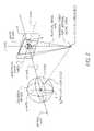
- FIG. 2is a schematic of the reference systems employed to describe the present invention
- FIGS. 3A–Cshow several examples of images with different formats and orientations
- FIGS. 4A–Bshow the effects on an image as a result of small angle camera rotation
- FIGS. 5A–Bshow an actual image that has been corrected by the method of this invention.
- FIG. 6is a diagram useful in describing the present invention.
- FIG. 1shows a block diagram of the present invention.
- the purpose of the present inventionis to estimate the amount of rotation of a camera relative to the scene at the time of image capture, based upon a digitized representation of an image.
- the source of the digitized imageis irrelevant.
- the digitized imagemay be a scan of a film negative, a scan of a photograph, or an image captured with a digital camera. It should be well understood that in cases where the digitized image is a scan of a hardcopy image that the rotation of the digitized image corresponds to the rotation of the source image.
- the method described hereinmay be used to automatically determine the amount of camera rotation at the time of capturing the photograph, for example; by first digitizing the photograph and then analyzing the resulting scan with the method of the preferred embodiment.
- the source imageis the photograph and the digital image is a result of the scan.
- the source imagemay for example be a large resolution digital image. This source image may then be decimated to generate the digital image that the method of the present embodiment operates upon. Again, the result from the present invention applies to both a source image and a digital image.
- Vanishing pointsare a useful feature for determining the amount of rotation of an image because of the many vertical parallel lines associated with human construction. Despite a left to right positioning of the camera (or other image capture device), the vanishing point associated with the vertical scene lines nearly always falls near the vertical axis of the image.
- FIG. 2shows a reference system employed with the present invention.
- a focal point 2representing the approximate location of the focal point of the lens used to capture the image, is located a distanced from the image plane 3 .
- the focal point 2represents the center of a Gaussian sphere.
- the x-axis and y-axisdefine the dimensionality of the image plane 3 .
- the z-axisis also defined as the “optical axis” of the system.
- the x′-axis and the y′-axisdefine a plane that is parallel to the image plane 3 .
- the image origin 4is defined as the point of intersection of the image plane with the optical axis, and is given in Cartesian coordinates as (0,0,f).
- the image originis assumed to be at the center of the distribution of pixels comprising the digital image, although this assumption may not be correct.
- the camerais constrained to only pivot up or down (pivoting solely about the x-axis)
- the vanishing point associated with vertical scene linesmust fall on the vertical axis of the image.
- a pleasing captured imageresults by maintaining a level camera during shooting the image. Attempting to keep the camera level applies whether the camera is held by hand or placed on a tripod or some other mechanical device.
- the vertical axis of the imageis defined as a preferable vanishing point location for achieving a user desired image composition.
- the captured imageis preferably represented as a level depiction of the captured scene with respect to the vertical lines within the scene.
- the vanishing point associated with vertical scene lineswill not fall on the vertical axis of the image.
- the angle from the vanishing point corresponding to the vertical scene lines to the vertical axis of the imageis equivalent to the amount that the camera was rotated about the optical axis.
- the vanishing point associated with horizontal lines in the scenemay fall on the horizontal axis of the image, but because of the scene composition it is just as likely that the vanishing point will fall elsewhere.
- the vanishing point location corresponding to the horizontal lines in the sceneis not constrained to fall near an image axis, but it is highly likely that the vanishing point associated with the vertical lines of the scene will fall near the vertical axis of the image.
- a vanishing pointis located near an image axis, it is far more likely that this vanishing point corresponds to a set of vertical scene lines than a set of horizontal scene lines.
- FIG. 2discloses an example of expressing a vanishing point location.
- a vanishing pointmay be expressed as a location on the image plane.
- Such a representation of the vanishing point locationperforms well when the vanishing point is located near the image origin, however, the coordinate locations along the x-axis and the y-axis may grow quite large.
- Another aspect of the invention illustrated in FIG. 2is a vanishing point representation scheme, commonly used in the field of vanishing point detection. In this representation, the vanishing point is represented with a Gaussian mapping.
- each location v on the image planehas a unique location v G on the Gaussian sphere.
- the vanishing point vector v Gis a unit vector extending in the direction from the focal point to the vanishing point location in the image plane.
- the image planeis positioned f distance from the optical origin of the system. Normally f distance represents the focal length. If the focal length is unknown, then a reasonable guess may be used. In one embodiment, f is the diagonal length of the imager. For example, where an image has a dimension of 512 pixels by 768 pixels, f equals 923.
- the vanishing point on the image planemay then be represented as the unit vector that points from the optical system's origin to the vanishing point on the image plane.
- This vectoris of length one and may be described as the coordinates of the intersection of a Gaussian sphere (a sphere of radius 1.0) centered at the optical system origin (the focal point) and the line passing through both the optical system origin and the vanishing point on the image plane.
- This vector representation of the vanishing pointis advantageous because it contains the entire space of the image plane.
- a digital imageis input to a vanishing point detector 12 .
- the purpose of the vanishing point detectoris to identify the locations of the vanishing points of the digital image.
- a vanishing pointis the result of the perspective projection of the three dimensional scene onto a two dimensional image plane.
- a vanishing pointrefers to the point in the image plane (a two dimensional projection of the three dimensional scene) where parallel lines in the scene meet. Vanishing points generally only have relevance for images containing images of a structure containing at least two line segments, generally from man-made structures.
- Several authorshave documented methods of automatically locating the vanishing points of an image. For example, S.
- the vanishing point detectormay include manually identifying the vanishing points using operator input.
- the vanishing point detector 12outputs the locations of all vanishing points identified for the image. Characteristically, the number of vanishing points determined for a single image is not greater than three, although this should not be viewed as a limitation.
- the vanishing points determined for the imageare output in the form of vanishing point vectors.
- the output of the vanishing point detectormay be represented as v Gm , where m ranges from 1 to M.
- mranges from 1 to M.
- the present inventioncannot draw any conclusions regarding image rotation from the location(s) of vanishing point(s).
- vanishing point vectors detected by the vanishing point detector 12are input to a vanishing point selector 13 .
- the purpose of vanishing point selector 13is to determine those vanishing points that may be useful for determining the amount of rotation (i.e. the rotation of the camera from the level position at the time of capture) of the digital image by using the information contained in the M vanishing point vectors.
- the vanishing point selector 13determines if any of the M vanishing points associated with the digital image may be used to determine the amount of rotation of the digital image. Those vanishing points which may be used to determine the format of the image are referred to as “rotation candidate vanishing points.”
- T 1is set at 0.5.
- the regions in the x G , y G plane in which such vanishing points lieare illustrated by cross hatching in FIG. 6 .
- the vanishing point selector 13outputs N (where N is between 0 and M) format candidate vanishing points.
- a vanishing point vector v Gmay be classified as a rotation candidate vanishing point if the following condition is met: ⁇ square root over ( x G 2 +y G 2 ) ⁇ > T 2
- T 2Values of T 2 between 0.3 and slightly less than 1 are useful in practicing the invention.
- the present inventiondoes not detect the rotation of the digital image using a feature based on vanishing point location.
- the rotation candidate vanishing pointis output from the vanishing point selector 13 and input to a rotation detector 14 .
- other informationmay also be input to the rotation detector 14 in order to aid the determination process.
- the format (an identification of the vertical axis of the image as will be described herein) or orientation (an identification of the top of the image)may also be input to the rotation detector 14 for the purpose of determining the rotation amount.
- the operation of the rotation detector 14is to determine the angle ⁇ between the vertical axis of the image and the vector pointing from the image origin to the vanishing point corresponding to the vertical lines in the scene.
- the angle ⁇corresponds to the amount of rotation of the capture device (for example a camera) about the optical axis.
- the vector v Gxyis a vector which generally points in a direction parallel to the vertical axis of the scene.
- the angles ⁇are determined to be the angles between the vector v Gxy and both the positive and negative vertical axes of the image.
- the vertical axis of an imageis the axis on the image plane parallel to either the x-axis or the y-axis which also passes through the “top” and “bottom” of the image.
- the vertical axis of the imagewill be further explained herein below. If the vertical axis of the image is known, then the angles ⁇ are computed by taking the inverse cosine of the dot product of the two vectors, as is well known in the art.
- angles ⁇are determined to each image axis (for a total of four angles ⁇ ).
- several angles ⁇are determined as the angle between the vector V Gxy representing the projection of the vanishing point onto the xy-plane and the image axes.
- the angle ⁇is determined to be the smallest (in an absolute value sense) of these angles ⁇ .
- the angle ⁇may be positive or negative in magnitude, indicating the direction of camera rotation.
- the output of the rotation detector 14is the angle ⁇ . Note that the angle ⁇ is expected to be equal to or less than ⁇ /4.
- FIG. 1shows that the identification of the vertical axis of the digital image is output from the rotation detector 14 and passed to an image transform 19 .
- this image transformmay also receive various other parameters, including the digital image itself.
- the operation of the image transform 19may be any number of image transformations that benefit from knowledge of image rotation.
- the angle ⁇ of the digital imagemay be stored as metadata by the image transform 19 .
- Metadatais generally defined as data corresponding to an image apart from actual pixel values.
- the function of the image transform 19may account for the rotation of the image by performing an image rotation in the opposite direction.
- Image rotationis well known by those skilled in the art of image processing.
- the amount the digital image must be rotatedis given by the negative of ⁇ .
- the vanishing point vectoris interchangeable with the vanishing point location given in Cartesian coordinates.
- FIG. 3shows several image examples useful for defining terms used herein.
- FIG. 3Ashows an example image of a person.
- the top of the imageis defined as the side of the image that was in the “up” direction from the photographer's perspective at the time of image capture. Identification of the top of an image solves the problem of orientation.
- the top of the imageclearly corresponds to the top of the subject's head. Note that the bottom of an image is always the image side opposite the image top.
- Also shown in FIG. 3Aare axes parallel to the x-axis and the y-axis passing through the image origin. These axes have herein been defined as the x′-axis, and the y′-axis, respectively, and shall herein be known collectively as image axes.
- the vertical axis of the imageis that line that passes through the top and bottom of the image, as well as the image origin and coincident with either the x′-axis or the y′-axis.
- the vertical axis of the imagedefines the format of the image, by specifying which two sides are top and bottom.
- the term “format”means the identity of the vertical axis of the image.
- the vertical axis of the imagedoes not specify which of the two sides is the top, thus the orientation of an image may remain unknown even when the format is known.
- the y′-axisis the vertical axis of the image.
- FIG. 3Bshows an example where the top of the image is the right image side.
- the vertical axis of the imageis the x′-axis.
- FIG. 3Cshows an example image where, like the image in FIG. 3A , the vertical axis of the image is the y′-axis. However, in this example the top of the image lies on the negative y′-axis.
- FIG. 4Ashows an embodiment similar to that of FIG. 3A , except for the fact that a simulated amount of camera rotation is included.
- FIG. 4Bdiscloses an embodiment to that of FIG. 3B with the addition of camera rotation. It is possible to show that the amount of the camera rotation (the angle from the level position) is the same as the angle ⁇ that the image is rotated. As described herein, the vanishing point locations detected from the image allow for the identification of this angle.
- FIG. 5Ashows an original image that has an apparent amount of camera rotation.
- the method of the present inventionwas applied to the original image and estimated that the amount of rotation of the original image in the counter-clockwise direction was 3.4 degrees.
- FIG. 5Bshows the corrected image, generated by rotating FIG. 5A by 3.4 degrees in the clockwise direction.
- the image transform 19performs a rotation of the digital image
- the image transform 19performs a rotation by an amount of ⁇ , the resulting image produced has a vanishing point on the vertical axis of the image (assuming that the value of ⁇ is correct).
- the image transform 19is a rotating transformation which operates by rotating the image. Such a transformation is a warping of the image, since the geometry of the image output from the image transform 19 has been modified relative to the geometry of the image input to the image transform 19 .
- the location of the rotation candidate vanishing point v G of the image input to the image transform 19is an undesirable vanishing point location, because it does not lie on the vertical axis of the image.
- the vertical axis of the imageis considered to be a preferable vanishing point location.
- preferable vanishing point locationsmay exist.
- the digital imagemay be modified by an image transform 19 designed to warp the image in such a manner that the image resulting from the image transform 19 has a vanishing point now located at infinity.
- the vanishing point of the image output from the image transform 19lies on the vertical axis of the image, and is therefore a preferable vanishing point location.
- the operation of the image transform 19is to warp the image in such a fashion that a vanishing point associated with the input image migrates from an undesirable vanishing point location to a desirable vanishing point location in the image output from the image transform 19 .
- an image transform 19may be created (either deterministically or empirically) to warp an image in such a manner as to relocate a vanishing point from an undesirable vanishing point location within the input image to a desirable vanishing point location within the resulting image.
Landscapes
- Engineering & Computer Science (AREA)
- Multimedia (AREA)
- Signal Processing (AREA)
- Physics & Mathematics (AREA)
- General Physics & Mathematics (AREA)
- Theoretical Computer Science (AREA)
- Computer Vision & Pattern Recognition (AREA)
- Health & Medical Sciences (AREA)
- General Health & Medical Sciences (AREA)
- Vascular Medicine (AREA)
- Image Analysis (AREA)
Abstract
Description
|xG|>
|yG|>
√{square root over (xG2+yG2)}>T2
γ=sign(xGyG)cos−1(
γ=sign(xGyG)cos−1(vGxy [·0,−1,0])
where sign(xGyG) represents the sign (−1 or +1) of the product of xGand yG. For example, when xGand yGare either both negative or both positive, the sign(xGyG)=1. Alternatively, when only xGor yGis negative then sign(xGyG)=−1.
| 2 | |
| 3 | image plane |
| 4 | |
| 12 | vanishing |
| 13 | vanishing |
| 14 | |
| 19 | image transform |
Claims (15)
|xG|>T1
OR
|yG|>T1
γ=sign(xGyG)cos−1(vGxy·[0,1,0])
γ=sign(xGyG)cos−1(vGxy·[0,−1,0])
γ=sign(xGyG)cos−1(vGxy·[1,0,0])
γ=sign(xGyG)cos−1(vGxy·[−1,0,0])
|xG|>T1
OR
|yG|>T1
|xG|>T1
OR
|yG|>T1
γ=sign(xGyG)cos−1(vGxy·[0,1,0])
γ=sign(xGyG)cos−1(vGxy·[0,−1,0])
γ=sign(xGyG)cos−1(vGxy·[1,0,0])
γ=sign(xGyG)cos−1(vGxy·[−1,0,0])
|xG|>T1
OR
|yG|>T1
Priority Applications (2)
| Application Number | Priority Date | Filing Date | Title |
|---|---|---|---|
| US09/663,056US6968094B1 (en) | 2000-03-27 | 2000-09-15 | Method of estimating and correcting camera rotation with vanishing point location |
| US11/134,593US7893963B2 (en) | 2000-03-27 | 2005-05-19 | Digital camera which estimates and corrects small camera rotations |
Applications Claiming Priority (2)
| Application Number | Priority Date | Filing Date | Title |
|---|---|---|---|
| US19240000P | 2000-03-27 | 2000-03-27 | |
| US09/663,056US6968094B1 (en) | 2000-03-27 | 2000-09-15 | Method of estimating and correcting camera rotation with vanishing point location |
Related Child Applications (1)
| Application Number | Title | Priority Date | Filing Date |
|---|---|---|---|
| US11/134,593Continuation-In-PartUS7893963B2 (en) | 2000-03-27 | 2005-05-19 | Digital camera which estimates and corrects small camera rotations |
Publications (1)
| Publication Number | Publication Date |
|---|---|
| US6968094B1true US6968094B1 (en) | 2005-11-22 |
Family
ID=35345009
Family Applications (1)
| Application Number | Title | Priority Date | Filing Date |
|---|---|---|---|
| US09/663,056Expired - Fee RelatedUS6968094B1 (en) | 2000-03-27 | 2000-09-15 | Method of estimating and correcting camera rotation with vanishing point location |
Country Status (1)
| Country | Link |
|---|---|
| US (1) | US6968094B1 (en) |
Cited By (26)
| Publication number | Priority date | Publication date | Assignee | Title |
|---|---|---|---|---|
| US20030152289A1 (en)* | 2002-02-13 | 2003-08-14 | Eastman Kodak Company | Method and system for determining image orientation |
| US20040165087A1 (en)* | 2003-02-25 | 2004-08-26 | Yasuhiro Harada | Reproducing apparatus, image data reproducing method, program and storage medium |
| US20050212931A1 (en)* | 2000-03-27 | 2005-09-29 | Eastman Kodak Company | Digital camera which estimates and corrects small camera rotations |
| US20050233284A1 (en)* | 2003-10-27 | 2005-10-20 | Pando Traykov | Optical sight system for use with weapon simulation system |
| US20060008172A1 (en)* | 2004-07-06 | 2006-01-12 | Lg Electronics Inc. | Image compensating system and method for a mobile terminal imaging device |
| US20060078214A1 (en)* | 2004-10-12 | 2006-04-13 | Eastman Kodak Company | Image processing based on direction of gravity |
| US20090208128A1 (en)* | 2008-02-15 | 2009-08-20 | Sony Corporation | Image processing method, recording medium carrying image processing program, and image processing apparatus |
| US20100014782A1 (en)* | 2008-07-15 | 2010-01-21 | Nuance Communications, Inc. | Automatic Correction of Digital Image Distortion |
| US20110163954A1 (en)* | 2010-01-04 | 2011-07-07 | Sungun Kim | Display device and control method thereof |
| US20110205377A1 (en)* | 2000-07-11 | 2011-08-25 | Phase One A/S | Digital camera with integrated accelerometers |
| US20120321216A1 (en)* | 2008-04-03 | 2012-12-20 | Abbyy Software Ltd. | Straightening Out Distorted Perspective on Images |
| US20140104437A1 (en)* | 2012-10-16 | 2014-04-17 | Qualcomm Incorporated | Sensor calibration and position estimation based on vanishing point determination |
| US8774556B2 (en) | 2011-11-30 | 2014-07-08 | Microsoft Corporation | Perspective correction using a reflection |
| US20160191783A1 (en)* | 2014-12-26 | 2016-06-30 | Xiaomi Inc. | Auto-focusing method and auto-focusing device |
| US20160205308A1 (en)* | 2015-01-09 | 2016-07-14 | Canon Kabushiki Kaisha | Display apparatus, image capturing apparatus, image capturing system, control method for display apparatus, control method for image capturing apparatus, and storage medium |
| US9955910B2 (en) | 2005-10-14 | 2018-05-01 | Aranz Healthcare Limited | Method of monitoring a surface feature and apparatus therefor |
| US20180122130A1 (en)* | 2016-10-28 | 2018-05-03 | Samsung Electronics Co., Ltd. | Image display apparatus, mobile device, and methods of operating the same |
| US10013527B2 (en) | 2016-05-02 | 2018-07-03 | Aranz Healthcare Limited | Automatically assessing an anatomical surface feature and securely managing information related to the same |
| US20190005621A1 (en)* | 2012-02-29 | 2019-01-03 | Google Llc | Systems, methods, and media for adjusting one or more images displayed to a viewer |
| CN111932608A (en)* | 2020-06-19 | 2020-11-13 | 广州图匠数据科技有限公司 | Monocular retail shelf attitude estimation method and device based on vanishing point detection |
| US10874302B2 (en) | 2011-11-28 | 2020-12-29 | Aranz Healthcare Limited | Handheld skin measuring or monitoring device |
| US11116407B2 (en) | 2016-11-17 | 2021-09-14 | Aranz Healthcare Limited | Anatomical surface assessment methods, devices and systems |
| US11282228B2 (en)* | 2018-05-08 | 2022-03-22 | Sony Corporation | Information processing device, information processing method, and program |
| US11348263B2 (en) | 2018-10-23 | 2022-05-31 | Samsung Electronics Co., Ltd. | Training method for detecting vanishing point and method and apparatus for detecting vanishing point |
| US11903723B2 (en) | 2017-04-04 | 2024-02-20 | Aranz Healthcare Limited | Anatomical surface assessment methods, devices and systems |
| US12039726B2 (en) | 2019-05-20 | 2024-07-16 | Aranz Healthcare Limited | Automated or partially automated anatomical surface assessment methods, devices and systems |
Citations (7)
| Publication number | Priority date | Publication date | Assignee | Title |
|---|---|---|---|---|
| US5325470A (en)* | 1991-03-11 | 1994-06-28 | Institute For Personalized Information Environment | Method of synthesizing real image and computer graphic in image processing system |
| US5798761A (en)* | 1996-01-26 | 1998-08-25 | Silicon Graphics, Inc. | Robust mapping of 2D cursor motion onto 3D lines and planes |
| US5967979A (en)* | 1995-11-14 | 1999-10-19 | Verg, Inc. | Method and apparatus for photogrammetric assessment of biological tissue |
| US5990900A (en)* | 1997-12-24 | 1999-11-23 | Be There Now, Inc. | Two-dimensional to three-dimensional image converting system |
| US6011585A (en) | 1996-01-19 | 2000-01-04 | Apple Computer, Inc. | Apparatus and method for rotating the display orientation of a captured image |
| US6226004B1 (en)* | 1997-09-12 | 2001-05-01 | Autodesk, Inc. | Modeling system using surface patterns and geometric relationships |
| US6591005B1 (en)* | 2000-03-27 | 2003-07-08 | Eastman Kodak Company | Method of estimating image format and orientation based upon vanishing point location |
- 2000
- 2000-09-15USUS09/663,056patent/US6968094B1/ennot_activeExpired - Fee Related
Patent Citations (7)
| Publication number | Priority date | Publication date | Assignee | Title |
|---|---|---|---|---|
| US5325470A (en)* | 1991-03-11 | 1994-06-28 | Institute For Personalized Information Environment | Method of synthesizing real image and computer graphic in image processing system |
| US5967979A (en)* | 1995-11-14 | 1999-10-19 | Verg, Inc. | Method and apparatus for photogrammetric assessment of biological tissue |
| US6011585A (en) | 1996-01-19 | 2000-01-04 | Apple Computer, Inc. | Apparatus and method for rotating the display orientation of a captured image |
| US5798761A (en)* | 1996-01-26 | 1998-08-25 | Silicon Graphics, Inc. | Robust mapping of 2D cursor motion onto 3D lines and planes |
| US6226004B1 (en)* | 1997-09-12 | 2001-05-01 | Autodesk, Inc. | Modeling system using surface patterns and geometric relationships |
| US5990900A (en)* | 1997-12-24 | 1999-11-23 | Be There Now, Inc. | Two-dimensional to three-dimensional image converting system |
| US6591005B1 (en)* | 2000-03-27 | 2003-07-08 | Eastman Kodak Company | Method of estimating image format and orientation based upon vanishing point location |
Non-Patent Citations (3)
| Title |
|---|
| Barnard, "Interpreting Perspective Images", Artificial Intelligence 21 (1983), Elsevier Science Publishers, B.V., pp. 435-462. |
| Chen et al., "Skew detection and reconstruction based on maximization of variance of transition-counts", Pattern Recognition 33 (2000), pp. 195-208. |
| Lutton et al., "Contribution to the Determination of Vanishing Points Using Hough Transform", IEEE Transactions on Pattern Analysis and Machine Intelligence, vol. 16, No. 4, Apr. 1994, pp. 430-438. |
Cited By (61)
| Publication number | Priority date | Publication date | Assignee | Title |
|---|---|---|---|---|
| US7893963B2 (en)* | 2000-03-27 | 2011-02-22 | Eastman Kodak Company | Digital camera which estimates and corrects small camera rotations |
| US20050212931A1 (en)* | 2000-03-27 | 2005-09-29 | Eastman Kodak Company | Digital camera which estimates and corrects small camera rotations |
| US8619146B2 (en) | 2000-07-11 | 2013-12-31 | Phase One A/S | Digital camera with integrated accelerometers |
| US20110205375A1 (en)* | 2000-07-11 | 2011-08-25 | Phase One A/S | Digital camera with integrated accelerometers |
| US20110205377A1 (en)* | 2000-07-11 | 2011-08-25 | Phase One A/S | Digital camera with integrated accelerometers |
| US8854482B2 (en) | 2000-07-11 | 2014-10-07 | Phase One A/S | Digital camera with integrated accelerometers |
| US8908053B2 (en)* | 2000-07-11 | 2014-12-09 | Phase One A/S | Digital camera with integrated accelerometers |
| US7215828B2 (en)* | 2002-02-13 | 2007-05-08 | Eastman Kodak Company | Method and system for determining image orientation |
| US20030152289A1 (en)* | 2002-02-13 | 2003-08-14 | Eastman Kodak Company | Method and system for determining image orientation |
| US20040165087A1 (en)* | 2003-02-25 | 2004-08-26 | Yasuhiro Harada | Reproducing apparatus, image data reproducing method, program and storage medium |
| US7616247B2 (en)* | 2003-02-25 | 2009-11-10 | Canon Kabushiki Kaisha | Reproducing apparatus, image data reproducing method, program, and storage medium |
| US20050233284A1 (en)* | 2003-10-27 | 2005-10-20 | Pando Traykov | Optical sight system for use with weapon simulation system |
| US20060008172A1 (en)* | 2004-07-06 | 2006-01-12 | Lg Electronics Inc. | Image compensating system and method for a mobile terminal imaging device |
| US7583858B2 (en)* | 2004-10-12 | 2009-09-01 | Eastman Kodak Company | Image processing based on direction of gravity |
| US20060078214A1 (en)* | 2004-10-12 | 2006-04-13 | Eastman Kodak Company | Image processing based on direction of gravity |
| US10827970B2 (en) | 2005-10-14 | 2020-11-10 | Aranz Healthcare Limited | Method of monitoring a surface feature and apparatus therefor |
| US9955910B2 (en) | 2005-10-14 | 2018-05-01 | Aranz Healthcare Limited | Method of monitoring a surface feature and apparatus therefor |
| US20120275720A1 (en)* | 2008-02-15 | 2012-11-01 | Sony Corporation | Image processing method, recording medium carrying image processing program, and image processing apparatus |
| SG155115A1 (en)* | 2008-02-15 | 2009-09-30 | Sony Corp | Image processing method, recording medium carrying image processing program, and image processing apparatus |
| US8588469B2 (en)* | 2008-02-15 | 2013-11-19 | Sony Corporation | Image processing method, recording medium carrying image processing program, and image processing apparatus |
| US8218820B2 (en)* | 2008-02-15 | 2012-07-10 | Sony Corporation | Image processing method, recording medium carrying image processing program, and image processing apparatus |
| US20090208128A1 (en)* | 2008-02-15 | 2009-08-20 | Sony Corporation | Image processing method, recording medium carrying image processing program, and image processing apparatus |
| US20120321216A1 (en)* | 2008-04-03 | 2012-12-20 | Abbyy Software Ltd. | Straightening Out Distorted Perspective on Images |
| US9477898B2 (en)* | 2008-04-03 | 2016-10-25 | Abbyy Development Llc | Straightening out distorted perspective on images |
| US20140307967A1 (en)* | 2008-04-03 | 2014-10-16 | Abbyy Development Llc | Straightening out distorted perspective on images |
| US8885972B2 (en)* | 2008-04-03 | 2014-11-11 | Abbyy Development Llc | Straightening out distorted perspective on images |
| US20100014782A1 (en)* | 2008-07-15 | 2010-01-21 | Nuance Communications, Inc. | Automatic Correction of Digital Image Distortion |
| US8285077B2 (en)* | 2008-07-15 | 2012-10-09 | Nuance Communications, Inc. | Automatic correction of digital image distortion |
| US8611596B2 (en)* | 2010-01-04 | 2013-12-17 | Lg Electronics Inc. | Display device and control method thereof |
| US20110163954A1 (en)* | 2010-01-04 | 2011-07-07 | Sungun Kim | Display device and control method thereof |
| US10874302B2 (en) | 2011-11-28 | 2020-12-29 | Aranz Healthcare Limited | Handheld skin measuring or monitoring device |
| US11850025B2 (en) | 2011-11-28 | 2023-12-26 | Aranz Healthcare Limited | Handheld skin measuring or monitoring device |
| US8983227B2 (en) | 2011-11-30 | 2015-03-17 | Microsoft Technology Licensing, Llc | Perspective correction using a reflection |
| US8774556B2 (en) | 2011-11-30 | 2014-07-08 | Microsoft Corporation | Perspective correction using a reflection |
| US11308583B2 (en)* | 2012-02-29 | 2022-04-19 | Google Llc | Systems, methods, and media for adjusting one or more images displayed to a viewer |
| US10540753B2 (en)* | 2012-02-29 | 2020-01-21 | Google Llc | Systems, methods, and media for adjusting one or more images displayed to a viewer |
| US12417513B2 (en) | 2012-02-29 | 2025-09-16 | Google Llc | Systems, methods, and media for adjusting one or more images displayed to a viewer |
| US20190005621A1 (en)* | 2012-02-29 | 2019-01-03 | Google Llc | Systems, methods, and media for adjusting one or more images displayed to a viewer |
| KR20150070277A (en)* | 2012-10-16 | 2015-06-24 | 퀄컴 인코포레이티드 | Sensor calibration and position estimation based on vanishing point determination |
| US20140104437A1 (en)* | 2012-10-16 | 2014-04-17 | Qualcomm Incorporated | Sensor calibration and position estimation based on vanishing point determination |
| US9135705B2 (en)* | 2012-10-16 | 2015-09-15 | Qualcomm Incorporated | Sensor calibration and position estimation based on vanishing point determination |
| US9361688B2 (en) | 2012-10-16 | 2016-06-07 | Qualcomm Incorporated | Sensor calibration and position estimation based on vanishing point determination |
| KR101639029B1 (en) | 2012-10-16 | 2016-07-12 | 퀄컴 인코포레이티드 | Sensor calibration and position estimation based on vanishing point determination |
| US20160191783A1 (en)* | 2014-12-26 | 2016-06-30 | Xiaomi Inc. | Auto-focusing method and auto-focusing device |
| US9729775B2 (en)* | 2014-12-26 | 2017-08-08 | Xiaomi Inc. | Auto-focusing method and auto-focusing device |
| US20160205308A1 (en)* | 2015-01-09 | 2016-07-14 | Canon Kabushiki Kaisha | Display apparatus, image capturing apparatus, image capturing system, control method for display apparatus, control method for image capturing apparatus, and storage medium |
| US9924086B2 (en)* | 2015-01-09 | 2018-03-20 | Canon Kabushiki Kaisha | Display apparatus, image capturing system, control method for display apparatus, and storage medium for displaying information based on attitude |
| US10777317B2 (en) | 2016-05-02 | 2020-09-15 | Aranz Healthcare Limited | Automatically assessing an anatomical surface feature and securely managing information related to the same |
| US11250945B2 (en) | 2016-05-02 | 2022-02-15 | Aranz Healthcare Limited | Automatically assessing an anatomical surface feature and securely managing information related to the same |
| US10013527B2 (en) | 2016-05-02 | 2018-07-03 | Aranz Healthcare Limited | Automatically assessing an anatomical surface feature and securely managing information related to the same |
| US11923073B2 (en) | 2016-05-02 | 2024-03-05 | Aranz Healthcare Limited | Automatically assessing an anatomical surface feature and securely managing information related to the same |
| US20180122130A1 (en)* | 2016-10-28 | 2018-05-03 | Samsung Electronics Co., Ltd. | Image display apparatus, mobile device, and methods of operating the same |
| US10810789B2 (en)* | 2016-10-28 | 2020-10-20 | Samsung Electronics Co., Ltd. | Image display apparatus, mobile device, and methods of operating the same |
| US12268472B2 (en) | 2016-11-17 | 2025-04-08 | ARANZ Medical Limited | Anatomical surface assessment methods, devices and systems |
| US11116407B2 (en) | 2016-11-17 | 2021-09-14 | Aranz Healthcare Limited | Anatomical surface assessment methods, devices and systems |
| US12279883B2 (en) | 2017-04-04 | 2025-04-22 | ARANZ Medical Limited | Anatomical surface assessment methods, devices and systems |
| US11903723B2 (en) | 2017-04-04 | 2024-02-20 | Aranz Healthcare Limited | Anatomical surface assessment methods, devices and systems |
| US11282228B2 (en)* | 2018-05-08 | 2022-03-22 | Sony Corporation | Information processing device, information processing method, and program |
| US11348263B2 (en) | 2018-10-23 | 2022-05-31 | Samsung Electronics Co., Ltd. | Training method for detecting vanishing point and method and apparatus for detecting vanishing point |
| US12039726B2 (en) | 2019-05-20 | 2024-07-16 | Aranz Healthcare Limited | Automated or partially automated anatomical surface assessment methods, devices and systems |
| CN111932608A (en)* | 2020-06-19 | 2020-11-13 | 广州图匠数据科技有限公司 | Monocular retail shelf attitude estimation method and device based on vanishing point detection |
Similar Documents
| Publication | Publication Date | Title |
|---|---|---|
| US6968094B1 (en) | Method of estimating and correcting camera rotation with vanishing point location | |
| US6591005B1 (en) | Method of estimating image format and orientation based upon vanishing point location | |
| US7893963B2 (en) | Digital camera which estimates and corrects small camera rotations | |
| US7583858B2 (en) | Image processing based on direction of gravity | |
| JP4349367B2 (en) | Estimation system, estimation method, and estimation program for estimating the position and orientation of an object | |
| CN108230252B (en) | Image processing method and device and electronic equipment | |
| US7313289B2 (en) | Image processing method and apparatus and computer-readable storage medium using improved distortion correction | |
| US10187546B2 (en) | Method and device for correcting document image captured by image pick-up device | |
| JP4238542B2 (en) | Face orientation estimation apparatus, face orientation estimation method, and face orientation estimation program | |
| US10452938B2 (en) | System and method for pattern detection and camera calibration | |
| US6965693B1 (en) | Image processor, image processing method, and recorded medium | |
| US8126206B2 (en) | Image processing apparatus, image processing method, and program | |
| US9049397B2 (en) | Image processing device and image processing method | |
| JP2003526841A (en) | Face extraction system and method based on biometrics | |
| US8619098B2 (en) | Methods and apparatuses for generating co-salient thumbnails for digital images | |
| WO2012172817A1 (en) | Image stabilization apparatus, image stabilization method, and document | |
| US20030152291A1 (en) | Tilt correction of electronic images | |
| US20100128927A1 (en) | Image processing apparatus and image processing method | |
| US20040207600A1 (en) | System and method for transforming an ordinary computer monitor into a touch screen | |
| US20090207258A1 (en) | Digital photographing apparatus, method of controlling the digital photographing apparatus, and recording medium having recorded thereon a program for executing the method | |
| JP4515208B2 (en) | Image processing method, apparatus, and program | |
| JP2006139369A (en) | Image processing method and apparatus, and program | |
| US8687854B2 (en) | Information processing apparatus, control method for the same, and computer-readable storage medium | |
| US7006706B2 (en) | Imaging apparatuses, mosaic image compositing methods, video stitching methods and edgemap generation methods | |
| US7602943B2 (en) | Image processing apparatus, image processing method, and image processing program |
Legal Events
| Date | Code | Title | Description |
|---|---|---|---|
| FEPP | Fee payment procedure | Free format text:PAYOR NUMBER ASSIGNED (ORIGINAL EVENT CODE: ASPN); ENTITY STATUS OF PATENT OWNER: LARGE ENTITY | |
| FEPP | Fee payment procedure | Free format text:PAYOR NUMBER ASSIGNED (ORIGINAL EVENT CODE: ASPN); ENTITY STATUS OF PATENT OWNER: LARGE ENTITY Free format text:PAYER NUMBER DE-ASSIGNED (ORIGINAL EVENT CODE: RMPN); ENTITY STATUS OF PATENT OWNER: LARGE ENTITY | |
| FPAY | Fee payment | Year of fee payment:4 | |
| AS | Assignment | Owner name:CITICORP NORTH AMERICA, INC., AS AGENT, NEW YORK Free format text:SECURITY INTEREST;ASSIGNORS:EASTMAN KODAK COMPANY;PAKON, INC.;REEL/FRAME:028201/0420 Effective date:20120215 | |
| AS | Assignment | Owner name:KODAK (NEAR EAST), INC., NEW YORK Free format text:PATENT RELEASE;ASSIGNORS:CITICORP NORTH AMERICA, INC.;WILMINGTON TRUST, NATIONAL ASSOCIATION;REEL/FRAME:029913/0001 Effective date:20130201 Owner name:EASTMAN KODAK COMPANY, NEW YORK Free format text:PATENT RELEASE;ASSIGNORS:CITICORP NORTH AMERICA, INC.;WILMINGTON TRUST, NATIONAL ASSOCIATION;REEL/FRAME:029913/0001 Effective date:20130201 Owner name:PAKON, INC., INDIANA Free format text:PATENT RELEASE;ASSIGNORS:CITICORP NORTH AMERICA, INC.;WILMINGTON TRUST, NATIONAL ASSOCIATION;REEL/FRAME:029913/0001 Effective date:20130201 Owner name:KODAK AVIATION LEASING LLC, NEW YORK Free format text:PATENT RELEASE;ASSIGNORS:CITICORP NORTH AMERICA, INC.;WILMINGTON TRUST, NATIONAL ASSOCIATION;REEL/FRAME:029913/0001 Effective date:20130201 Owner name:QUALEX INC., NORTH CAROLINA Free format text:PATENT RELEASE;ASSIGNORS:CITICORP NORTH AMERICA, INC.;WILMINGTON TRUST, NATIONAL ASSOCIATION;REEL/FRAME:029913/0001 Effective date:20130201 Owner name:NPEC INC., NEW YORK Free format text:PATENT RELEASE;ASSIGNORS:CITICORP NORTH AMERICA, INC.;WILMINGTON TRUST, NATIONAL ASSOCIATION;REEL/FRAME:029913/0001 Effective date:20130201 Owner name:KODAK REALTY, INC., NEW YORK Free format text:PATENT RELEASE;ASSIGNORS:CITICORP NORTH AMERICA, INC.;WILMINGTON TRUST, NATIONAL ASSOCIATION;REEL/FRAME:029913/0001 Effective date:20130201 Owner name:KODAK PHILIPPINES, LTD., NEW YORK Free format text:PATENT RELEASE;ASSIGNORS:CITICORP NORTH AMERICA, INC.;WILMINGTON TRUST, NATIONAL ASSOCIATION;REEL/FRAME:029913/0001 Effective date:20130201 Owner name:CREO MANUFACTURING AMERICA LLC, WYOMING Free format text:PATENT RELEASE;ASSIGNORS:CITICORP NORTH AMERICA, INC.;WILMINGTON TRUST, NATIONAL ASSOCIATION;REEL/FRAME:029913/0001 Effective date:20130201 Owner name:EASTMAN KODAK INTERNATIONAL CAPITAL COMPANY, INC., Free format text:PATENT RELEASE;ASSIGNORS:CITICORP NORTH AMERICA, INC.;WILMINGTON TRUST, NATIONAL ASSOCIATION;REEL/FRAME:029913/0001 Effective date:20130201 Owner name:FPC INC., CALIFORNIA Free format text:PATENT RELEASE;ASSIGNORS:CITICORP NORTH AMERICA, INC.;WILMINGTON TRUST, NATIONAL ASSOCIATION;REEL/FRAME:029913/0001 Effective date:20130201 Owner name:FAR EAST DEVELOPMENT LTD., NEW YORK Free format text:PATENT RELEASE;ASSIGNORS:CITICORP NORTH AMERICA, INC.;WILMINGTON TRUST, NATIONAL ASSOCIATION;REEL/FRAME:029913/0001 Effective date:20130201 Owner name:KODAK PORTUGUESA LIMITED, NEW YORK Free format text:PATENT RELEASE;ASSIGNORS:CITICORP NORTH AMERICA, INC.;WILMINGTON TRUST, NATIONAL ASSOCIATION;REEL/FRAME:029913/0001 Effective date:20130201 Owner name:KODAK AMERICAS, LTD., NEW YORK Free format text:PATENT RELEASE;ASSIGNORS:CITICORP NORTH AMERICA, INC.;WILMINGTON TRUST, NATIONAL ASSOCIATION;REEL/FRAME:029913/0001 Effective date:20130201 Owner name:KODAK IMAGING NETWORK, INC., CALIFORNIA Free format text:PATENT RELEASE;ASSIGNORS:CITICORP NORTH AMERICA, INC.;WILMINGTON TRUST, NATIONAL ASSOCIATION;REEL/FRAME:029913/0001 Effective date:20130201 Owner name:LASER-PACIFIC MEDIA CORPORATION, NEW YORK Free format text:PATENT RELEASE;ASSIGNORS:CITICORP NORTH AMERICA, INC.;WILMINGTON TRUST, NATIONAL ASSOCIATION;REEL/FRAME:029913/0001 Effective date:20130201 | |
| AS | Assignment | Owner name:INTELLECTUAL VENTURES FUND 83 LLC, NEVADA Free format text:ASSIGNMENT OF ASSIGNORS INTEREST;ASSIGNOR:EASTMAN KODAK COMPANY;REEL/FRAME:030304/0525 Effective date:20130201 | |
| REMI | Maintenance fee reminder mailed | ||
| LAPS | Lapse for failure to pay maintenance fees | ||
| STCH | Information on status: patent discontinuation | Free format text:PATENT EXPIRED DUE TO NONPAYMENT OF MAINTENANCE FEES UNDER 37 CFR 1.362 | |
| FP | Lapsed due to failure to pay maintenance fee | Effective date:20131122 | |
| AS | Assignment | Owner name:MONUMENT PEAK VENTURES, LLC, TEXAS Free format text:RELEASE BY SECURED PARTY;ASSIGNOR:INTELLECTUAL VENTURES FUND 83 LLC;REEL/FRAME:064599/0304 Effective date:20230728 |