US6967612B1 - System and method for standoff detection of human carried explosives - Google Patents
System and method for standoff detection of human carried explosivesDownload PDFInfo
- Publication number
- US6967612B1 US6967612B1US10/970,465US97046504AUS6967612B1US 6967612 B1US6967612 B1US 6967612B1US 97046504 AUS97046504 AUS 97046504AUS 6967612 B1US6967612 B1US 6967612B1
- Authority
- US
- United States
- Prior art keywords
- radar
- detection
- threat
- hce
- human
- Prior art date
- Legal status (The legal status is an assumption and is not a legal conclusion. Google has not performed a legal analysis and makes no representation as to the accuracy of the status listed.)
- Expired - Lifetime, expires
Links
- 238000001514detection methodMethods0.000titleclaimsabstractdescription105
- 239000002360explosiveSubstances0.000titleclaimsabstractdescription60
- 238000000034methodMethods0.000titleclaimsabstractdescription51
- 238000004891communicationMethods0.000claimsabstractdescription14
- 241000282412HomoSpecies0.000claimsabstractdescription9
- 238000003384imaging methodMethods0.000claimsdescription28
- 230000033001locomotionEffects0.000claimsdescription28
- 230000010287polarizationEffects0.000claimsdescription27
- 238000012360testing methodMethods0.000claimsdescription22
- 230000005855radiationEffects0.000claimsdescription18
- 238000005259measurementMethods0.000claimsdescription12
- 238000012545processingMethods0.000claimsdescription9
- 230000003993interactionEffects0.000claimsdescription5
- 230000008859changeEffects0.000claimsdescription4
- XLYOFNOQVPJJNP-UHFFFAOYSA-NwaterSubstancesOXLYOFNOQVPJJNP-UHFFFAOYSA-N0.000claimsdescription4
- 230000005670electromagnetic radiationEffects0.000claimsdescription2
- 239000000203mixtureSubstances0.000claimsdescription2
- 230000008685targetingEffects0.000claims2
- 238000013500data storageMethods0.000claims1
- 238000001914filtrationMethods0.000claims1
- 238000004422calculation algorithmMethods0.000description11
- 230000004044responseEffects0.000description11
- 206010010144Completed suicideDiseases0.000description10
- 238000005516engineering processMethods0.000description9
- 238000013467fragmentationMethods0.000description9
- 238000006062fragmentation reactionMethods0.000description9
- 238000010586diagramMethods0.000description8
- 210000000779thoracic wallAnatomy0.000description8
- 238000004458analytical methodMethods0.000description7
- 239000000463materialSubstances0.000description6
- 239000002184metalSubstances0.000description6
- 229910052751metalInorganic materials0.000description6
- 230000000116mitigating effectEffects0.000description6
- 210000000038chestAnatomy0.000description5
- 230000008569processEffects0.000description5
- 230000009977dual effectEffects0.000description4
- 239000000284extractSubstances0.000description4
- 238000013459approachMethods0.000description3
- 238000007635classification algorithmMethods0.000description3
- 230000006870functionEffects0.000description3
- 230000000007visual effectEffects0.000description3
- IJGRMHOSHXDMSA-UHFFFAOYSA-NAtomic nitrogenChemical compoundN#NIJGRMHOSHXDMSA-UHFFFAOYSA-N0.000description2
- 230000003044adaptive effectEffects0.000description2
- 239000002131composite materialSubstances0.000description2
- 238000012937correctionMethods0.000description2
- 238000013461designMethods0.000description2
- 230000000694effectsEffects0.000description2
- 230000007613environmental effectEffects0.000description2
- 238000005286illuminationMethods0.000description2
- 230000005865ionizing radiationEffects0.000description2
- 231100001160nonlethalToxicity0.000description2
- 239000002245particleSubstances0.000description2
- 230000000149penetrating effectEffects0.000description2
- 238000002310reflectometryMethods0.000description2
- 238000005070samplingMethods0.000description2
- 230000003068static effectEffects0.000description2
- 239000000126substanceSubstances0.000description2
- 210000001519tissueAnatomy0.000description2
- 238000002604ultrasonographyMethods0.000description2
- 238000012935AveragingMethods0.000description1
- 241000282465CanisSpecies0.000description1
- 206010028980NeoplasmDiseases0.000description1
- 238000010521absorption reactionMethods0.000description1
- 230000009471actionEffects0.000description1
- 210000000577adipose tissueAnatomy0.000description1
- 230000002547anomalous effectEffects0.000description1
- QVGXLLKOCUKJST-UHFFFAOYSA-Natomic oxygenChemical compound[O]QVGXLLKOCUKJST-UHFFFAOYSA-N0.000description1
- 230000009286beneficial effectEffects0.000description1
- 230000005540biological transmissionEffects0.000description1
- 239000000919ceramicSubstances0.000description1
- 230000001427coherent effectEffects0.000description1
- 239000003086colorantSubstances0.000description1
- 230000006378damageEffects0.000description1
- 230000001419dependent effectEffects0.000description1
- 230000001066destructive effectEffects0.000description1
- 238000011161developmentMethods0.000description1
- 230000018109developmental processEffects0.000description1
- 239000003814drugSubstances0.000description1
- 229940079593drugDrugs0.000description1
- 230000005684electric fieldEffects0.000description1
- 230000005672electromagnetic fieldEffects0.000description1
- 238000000605extractionMethods0.000description1
- 230000002349favourable effectEffects0.000description1
- 230000008713feedback mechanismEffects0.000description1
- 238000010304firingMethods0.000description1
- 239000012634fragmentSubstances0.000description1
- 238000004817gas chromatographyMethods0.000description1
- 238000009434installationMethods0.000description1
- 238000011835investigationMethods0.000description1
- 231100000518lethalToxicity0.000description1
- 230000001665lethal effectEffects0.000description1
- 238000004949mass spectrometryMethods0.000description1
- 230000007246mechanismEffects0.000description1
- 239000007769metal materialSubstances0.000description1
- 238000012986modificationMethods0.000description1
- 230000004048modificationEffects0.000description1
- 238000012544monitoring processMethods0.000description1
- 210000003205muscleAnatomy0.000description1
- 229910052757nitrogenInorganic materials0.000description1
- 230000003287optical effectEffects0.000description1
- 238000005457optimizationMethods0.000description1
- 239000001301oxygenSubstances0.000description1
- 229910052760oxygenInorganic materials0.000description1
- 210000004258portal systemAnatomy0.000description1
- 238000011160researchMethods0.000description1
- 238000012552reviewMethods0.000description1
- 238000012216screeningMethods0.000description1
- 230000011218segmentationEffects0.000description1
- 210000003491skinAnatomy0.000description1
- 238000007920subcutaneous administrationMethods0.000description1
- 210000004304subcutaneous tissueAnatomy0.000description1
- 230000001629suppressionEffects0.000description1
- 238000010408sweepingMethods0.000description1
- 230000000699topical effectEffects0.000description1
- 230000001960triggered effectEffects0.000description1
Images


Classifications
- G—PHYSICS
- G01—MEASURING; TESTING
- G01S—RADIO DIRECTION-FINDING; RADIO NAVIGATION; DETERMINING DISTANCE OR VELOCITY BY USE OF RADIO WAVES; LOCATING OR PRESENCE-DETECTING BY USE OF THE REFLECTION OR RERADIATION OF RADIO WAVES; ANALOGOUS ARRANGEMENTS USING OTHER WAVES
- G01S13/00—Systems using the reflection or reradiation of radio waves, e.g. radar systems; Analogous systems using reflection or reradiation of waves whose nature or wavelength is irrelevant or unspecified
- G01S13/88—Radar or analogous systems specially adapted for specific applications
- G01S13/887—Radar or analogous systems specially adapted for specific applications for detection of concealed objects, e.g. contraband or weapons
- G—PHYSICS
- G01—MEASURING; TESTING
- G01S—RADIO DIRECTION-FINDING; RADIO NAVIGATION; DETERMINING DISTANCE OR VELOCITY BY USE OF RADIO WAVES; LOCATING OR PRESENCE-DETECTING BY USE OF THE REFLECTION OR RERADIATION OF RADIO WAVES; ANALOGOUS ARRANGEMENTS USING OTHER WAVES
- G01S13/00—Systems using the reflection or reradiation of radio waves, e.g. radar systems; Analogous systems using reflection or reradiation of waves whose nature or wavelength is irrelevant or unspecified
- G01S13/02—Systems using reflection of radio waves, e.g. primary radar systems; Analogous systems
- G01S13/04—Systems determining presence of a target
- G—PHYSICS
- G01—MEASURING; TESTING
- G01S—RADIO DIRECTION-FINDING; RADIO NAVIGATION; DETERMINING DISTANCE OR VELOCITY BY USE OF RADIO WAVES; LOCATING OR PRESENCE-DETECTING BY USE OF THE REFLECTION OR RERADIATION OF RADIO WAVES; ANALOGOUS ARRANGEMENTS USING OTHER WAVES
- G01S13/00—Systems using the reflection or reradiation of radio waves, e.g. radar systems; Analogous systems using reflection or reradiation of waves whose nature or wavelength is irrelevant or unspecified
- G01S13/02—Systems using reflection of radio waves, e.g. primary radar systems; Analogous systems
- G01S13/06—Systems determining position data of a target
- G01S13/08—Systems for measuring distance only
- G01S13/32—Systems for measuring distance only using transmission of continuous waves, whether amplitude-, frequency-, or phase-modulated, or unmodulated
- G01S13/34—Systems for measuring distance only using transmission of continuous waves, whether amplitude-, frequency-, or phase-modulated, or unmodulated using transmission of continuous, frequency-modulated waves while heterodyning the received signal, or a signal derived therefrom, with a locally-generated signal related to the contemporaneously transmitted signal
- G—PHYSICS
- G01—MEASURING; TESTING
- G01S—RADIO DIRECTION-FINDING; RADIO NAVIGATION; DETERMINING DISTANCE OR VELOCITY BY USE OF RADIO WAVES; LOCATING OR PRESENCE-DETECTING BY USE OF THE REFLECTION OR RERADIATION OF RADIO WAVES; ANALOGOUS ARRANGEMENTS USING OTHER WAVES
- G01S13/00—Systems using the reflection or reradiation of radio waves, e.g. radar systems; Analogous systems using reflection or reradiation of waves whose nature or wavelength is irrelevant or unspecified
- G01S13/66—Radar-tracking systems; Analogous systems
- G—PHYSICS
- G01—MEASURING; TESTING
- G01S—RADIO DIRECTION-FINDING; RADIO NAVIGATION; DETERMINING DISTANCE OR VELOCITY BY USE OF RADIO WAVES; LOCATING OR PRESENCE-DETECTING BY USE OF THE REFLECTION OR RERADIATION OF RADIO WAVES; ANALOGOUS ARRANGEMENTS USING OTHER WAVES
- G01S13/00—Systems using the reflection or reradiation of radio waves, e.g. radar systems; Analogous systems using reflection or reradiation of waves whose nature or wavelength is irrelevant or unspecified
- G01S13/86—Combinations of radar systems with non-radar systems, e.g. sonar, direction finder
- G01S13/867—Combination of radar systems with cameras
- G—PHYSICS
- G01—MEASURING; TESTING
- G01S—RADIO DIRECTION-FINDING; RADIO NAVIGATION; DETERMINING DISTANCE OR VELOCITY BY USE OF RADIO WAVES; LOCATING OR PRESENCE-DETECTING BY USE OF THE REFLECTION OR RERADIATION OF RADIO WAVES; ANALOGOUS ARRANGEMENTS USING OTHER WAVES
- G01S7/00—Details of systems according to groups G01S13/00, G01S15/00, G01S17/00
- G01S7/02—Details of systems according to groups G01S13/00, G01S15/00, G01S17/00 of systems according to group G01S13/00
- G01S7/024—Details of systems according to groups G01S13/00, G01S15/00, G01S17/00 of systems according to group G01S13/00 using polarisation effects
- G—PHYSICS
- G01—MEASURING; TESTING
- G01S—RADIO DIRECTION-FINDING; RADIO NAVIGATION; DETERMINING DISTANCE OR VELOCITY BY USE OF RADIO WAVES; LOCATING OR PRESENCE-DETECTING BY USE OF THE REFLECTION OR RERADIATION OF RADIO WAVES; ANALOGOUS ARRANGEMENTS USING OTHER WAVES
- G01S7/00—Details of systems according to groups G01S13/00, G01S15/00, G01S17/00
- G01S7/02—Details of systems according to groups G01S13/00, G01S15/00, G01S17/00 of systems according to group G01S13/00
- G01S7/41—Details of systems according to groups G01S13/00, G01S15/00, G01S17/00 of systems according to group G01S13/00 using analysis of echo signal for target characterisation; Target signature; Target cross-section
- G01S7/411—Identification of targets based on measurements of radar reflectivity
- G01S7/412—Identification of targets based on measurements of radar reflectivity based on a comparison between measured values and known or stored values
- G—PHYSICS
- G01—MEASURING; TESTING
- G01S—RADIO DIRECTION-FINDING; RADIO NAVIGATION; DETERMINING DISTANCE OR VELOCITY BY USE OF RADIO WAVES; LOCATING OR PRESENCE-DETECTING BY USE OF THE REFLECTION OR RERADIATION OF RADIO WAVES; ANALOGOUS ARRANGEMENTS USING OTHER WAVES
- G01S7/00—Details of systems according to groups G01S13/00, G01S15/00, G01S17/00
- G01S7/02—Details of systems according to groups G01S13/00, G01S15/00, G01S17/00 of systems according to group G01S13/00
- G01S7/41—Details of systems according to groups G01S13/00, G01S15/00, G01S17/00 of systems according to group G01S13/00 using analysis of echo signal for target characterisation; Target signature; Target cross-section
- G01S7/414—Discriminating targets with respect to background clutter
- G—PHYSICS
- G01—MEASURING; TESTING
- G01S—RADIO DIRECTION-FINDING; RADIO NAVIGATION; DETERMINING DISTANCE OR VELOCITY BY USE OF RADIO WAVES; LOCATING OR PRESENCE-DETECTING BY USE OF THE REFLECTION OR RERADIATION OF RADIO WAVES; ANALOGOUS ARRANGEMENTS USING OTHER WAVES
- G01S7/00—Details of systems according to groups G01S13/00, G01S15/00, G01S17/00
- G01S7/02—Details of systems according to groups G01S13/00, G01S15/00, G01S17/00 of systems according to group G01S13/00
- G01S7/41—Details of systems according to groups G01S13/00, G01S15/00, G01S17/00 of systems according to group G01S13/00 using analysis of echo signal for target characterisation; Target signature; Target cross-section
- G01S7/415—Identification of targets based on measurements of movement associated with the target
- G—PHYSICS
- G01—MEASURING; TESTING
- G01S—RADIO DIRECTION-FINDING; RADIO NAVIGATION; DETERMINING DISTANCE OR VELOCITY BY USE OF RADIO WAVES; LOCATING OR PRESENCE-DETECTING BY USE OF THE REFLECTION OR RERADIATION OF RADIO WAVES; ANALOGOUS ARRANGEMENTS USING OTHER WAVES
- G01S13/00—Systems using the reflection or reradiation of radio waves, e.g. radar systems; Analogous systems using reflection or reradiation of waves whose nature or wavelength is irrelevant or unspecified
- G01S13/86—Combinations of radar systems with non-radar systems, e.g. sonar, direction finder
- G01S13/865—Combination of radar systems with lidar systems
Definitions
- the present inventionrelates to devices, systems and methods for remotely detecting concealed weapons, and particularly to system and methods for remotely detecting human carried explosives.
- HCEHuman Carried Explosives
- the safe evacuation distanceis proportional to the cube root of the device weight multiplied by a destruction factor that varies with munitions type.
- a typical suicide bomber payloadconsisting of thirty pounds of explosive surrounded by fragmentary shrapnel yields a safe evacuation distance of approximately one hundred meters.
- a Claymore mine with a shaped chargehas a safe evacuation distance of approximately one hundred meters, whereas a car bomb typically has a safe evacuation distance of four hundred fifty-seven meters.
- radarAlthough radar easily reaches potential threats at safe evacuation distances (standoff ranges), devices lacking metal fragmentation are transparent to conventional radar solutions. Moreover, conventional radar solutions that rely on radar cross section (RCS) measurements alone cannot reliably discriminate between humans, humans with body clutter (e.g., cell phone, belt buckle, etc.), and humans carrying fragmentation and explosives.
- RCSradar cross section
- a sensorIn order to separate a potential detection from random materials in the background environment of a potential threat and to localize a detection to a specific individual, a sensor is required having a small enough field of view so that it has enough resolution on a single individual being interrogated as a potential threat that a positive detection can be associated with the individual separate from his background and other individuals around him. Solving this problem requires a sensor with a relatively narrow field of view (FOV) of approximately a one-half to one degree visual arc at 100 meters if the sensor's FOV is going to correspond to one individual person. Such a narrow FOV requires some precise method for pointing the sensor at potential threats.
- FOVfield of view
- FORuseful field of regard
- 600 of visual arcthe sensor must be moved sequentially to every potential individual who might be carrying an explosive device. Returns from vehicles, buildings, signs, and other objects in the background must be ignored.
- Many proposed detection systemspostulate a skilled human operator to point the device at individual potential threats to solve this problem.
- suicide bombershave been observed to have been driven near to their target by accomplices and then to have exited the vehicle and to have run to their target and detonate. Consequently, the time to detect and interdict a suicide bomber may be only tens of seconds, and a practical system will have a method to continuously scan and examine all potential threats in a field of regard. Examining and identifying individual people at distances greater than 25 meters and rapidly pointing a narrow FOV detection sensor at each in turn covering a wide FOR every few seconds is beyond the capability of human operators in situations with more than a few potential threats.
- Bomb detection technologiesgenerally fall into two categories: direct methods designed to detect high explosives based on chemical properties, and indirect methods that look for anomalous signatures associated with bomb devices. None of these techniques are capable of detecting HCE threats at standoff ranges.
- Direct methods for bomb detectionexploit the fact that high explosives contain large amounts of nitrogen and oxygen in their molecular composition.
- Both bulk and trace detection methodsuse sampling methods designed to measure the chemical properties of the material, and both require that the material be placed in close proximity to the sensor.
- the main application of direct explosive detection methodsis in portal systems.
- Bulk detection methodsmeasure the interaction between the sample under investigation and a penetrating radiation wave, such as ionizing radiation or electromagnetic radiation. Bulk detection methods can be used on sealed packages, including concealed threats. However, methods that use ionizing radiation may not be suitable for use in screening of human subjects.
- a penetrating radiation wavesuch as ionizing radiation or electromagnetic radiation.
- Trace detection methodsare based on direct interaction with the material and require that some amount of the explosive be present on the outside of the package in the form of particle residue or vapors. Both canines and gas chromatography methods ingest vapors and hence need to be close enough to the suspect article to acquire a sample of the vapor. Particle-based detection methods, such as laser ionizing mass spectroscopy, use optical methods for interrogating samples, but detector noise limitations require that the sample be proximal to the laser.
- Indirect detection methodsare designed to detect anomalies in human signatures that are consistent with concealed bomb devices.
- the current standard practiceis limited to short-range or portal based systems.
- Metal detectorsare used to detect the presence of metal fragmentation and are of questionable use against devices that do not employ metallic fragmentation.
- Thermal and passive millimeter wave (MMW) systemsexploit the fact that human skin reflectivity differs from that of metal or explosive materials. Both thermal and MMW radiation pass through clothing.
- Passive imaging systemscollect an image of devices concealed under clothing in outdoor settings using the illumination of the cold sky. Imaging devices require trained operators to point the device and interpret the images, resulting in an increase in labor and privacy concerns, and in longer times to check each potential threat.
- the Huguenin systemis an active imaging system designed for detecting contraband on a conveyor belt with a constant background at close range. Polarized returns are used by an operator to adjust contrast with the background, and a skilled operator is required to interpret the images as the conveyor scrolls objects past the sensor.
- U.S. Pat. No. 5,829,437issued to J. Bridges in November 1998, discloses a system and method by which cancers in heterogeneous tissue is located and detected by using the backscatter signal returns from microwave radiation.
- the '437 deviceis not a stand-off device and requires contact with the patient.
- the Chadwick patentsare specifically illustrated by examples devoted to the detection of handguns, generally from laboratory studies, and do not address the problem of focusing the radar over a wide field at ranges up to one hundred meters or greater, and do not address the problem of detecting and identifying human subjects at such ranges, nor the problem of detecting nonmetallic objects by radar.
- U.S. Pat. No. 6,359,582issued to MacAleese et al. in March 2002, discloses a weapons detector utilizing a handheld radar system and signal processor to detect the presence of a plurality of self-resonant frequencies in the backscattered signals of a target between 4–15 yards. Although suitable for guns and similar devices, HCE devices must be detected at a much greater stand-off distance.
- the systemincludes an infrared/vision based system (FLIR) and a millimeter wave radar at 77 GHz slaved to the vision system on a two-axis pan and tilt mechanism.
- FLIRinfrared/vision based system
- the vision systemis stepped across a field of interest, and when motion is detected, a target track is established.
- the vision systemis used to define geometric shape and angular location, and Doppler radar pulses provide range and speed of movement, which are fused to establish a radar cross section and to confirm target and range.
- the systemhas been reported successful in detecting a human at ranges of 100 m–300 m.
- a scanning radaris added to the system for 360° detection of other potential targets while the system is tracking an initial target.
- the system and method for standoff detection of human carried explosivesautomatically detects HCE at ranges between 10 m–200 m, preferably about one hundred meters, and within seconds alerts an operator to HCE threats.
- the system and methodemploy a polarized radar system emitting a narrow beam, preferably between about 0.5° to 1°, to detect either fragmentation or nonfragmentation explosives by comparison of the energy differential between co-polarized and cross-polarized reflections from a target to reference values of similar targets not carrying explosives.
- the system and methodemploy radar only, operated in either a scan mode or a track mode, mounted on a pan and tilt two-axis gimbal, and software for assessment of the target threat.
- the system and methoduse a vision-based sensor collocated with the radar to detect and assess the target threat.
- the systemis preferably low-cost and/or portable, and may include a multi-sensor processor, an operator console, and a wide-band wireless communications link to a handheld display.
- the multi-sensor processorreceives video feed from at least one camera and automatically detects and tracks all humans in the field of view. Using track data to continuously cue the narrow beam radar to a subject of interest, the radar repeatedly interrogates cued objects, producing a multi-polarity radar range profile for each interrogation event.
- Range profiles and associated featuresare automatically fused over time until sufficient evidence is accrued to support a threat/non-threat declaration hypothesis. Once a decision is made, the system alerts operators through a wireless handheld display.
- the vision-based systemmay be any imaging system, and may include at least one Ladar, Lidar, infrared, multispectral, hyperspectral, or imaging radar output signal instead of or in addition to a video output signal.
- the radar systemmay be dual polarized with either HH (horizontal transmit-horizontal receive) and HV (horizontal transmit-vertical receive), or VV (vertical transmit-horizontal receive) and VH (vertical transmit-horizontal receive), alternating polarization (HH and HV alternating with VV and VH), fully polarimetric (HH, VV, HV and VH), or may use either right or left circular polarization.
- the differential between the co-polarized reflection and the cross-polarized reflectionmay be a simple difference in energy levels, but is preferably calculated as a ratio referred to as an extract RF discriminant.
- FIG. 1is an environmental view of a system for standoff detection of human carried explosives according to the present invention utilizing radar alone.
- FIG. 2is a flowchart showing the steps of a method for using the system of FIG. 1 .
- FIG. 3is an environmental view of a System for standoff detection of human carried explosives according to the present invention which incorporates both radar and video.
- FIG. 4is a flowchart showing the steps of a method for using the system of FIG. 3 .
- FIG. 5is a block diagram illustrating the radar system and pointing control detail of a system according to the present invention.
- FIG. 6is a schematic diagram detailing the radar antenna installation according to the present invention.
- FIG. 7is a block diagram of a decision process using the system according to FIG. 3 .
- FIG. 8Ais a block diagram of the radar only detection system of FIG. 1 .
- FIG. 8Bis a block diagram of the radar with video detection system of FIG. 3 .
- FIG. 9is a block diagram of a network of HCE detection systems according to the present invention showing the use of multiple radar fields of regard for detection over a wide area of surveillance.
- the present inventionis a Human Carried Explosive Detection system and method for standoff detection of human carried explosives (HCE).
- the “System”has several embodiments and is designed to automatically detect HCE out to a range of between about ten meters to two hundred meters, preferably about one hundred meters, and within seconds alerts an operator to HCE threats.
- the human chestgives a characteristic scattered response signature when excited by the electromagnetic field produced by radar.
- This chest wall response signatureis modified when non radar-transparent objects, such as explosive devices or concealed weapons, are placed on or near the chest.
- Signature modificationcan take the form of additional energy returns from highly reflective components (metal objects) or attenuation if the device obscures the radar view of the chest.
- the radar view of the chest wallcan become obscured and there is the possibility of collecting a radar return from the device, either directly or indirectly, as in the case of an interaction between the chest wall and the device.
- Obscuration of the chestinduces changes in the expected chest wall signature.
- Direct radar returns from a threat device placed between the chest wall and the radarproduce near-range returns that appear closer to the radar and can be separated from the chest wall return.
- the HCE Detection Systemdetects the induced changes in the return RF signature from the chest wall due to non radar-transparent objects, both reflective and non-reflective.
- the present inventorshave conducted tests with 3-D geometric models of a six-foot human using three dielectric layers that model the electrical properties of skin, subcutaneous or fatty tissue, and muscle tissue.
- the testswere conducted on a model not carrying explosives, a model equipped with a suicide bomber vest carrying, fragmentation explosives, and a suicide bomber vest carrying explosives only without fragments.
- both the fragmentation explosives model and the explosives only modelshowed a 30 dB energy gain over the bare torso in a cross-polarized channel (VH) as compared to a bare torso.
- VHcross-polarized channel
- the problemis to focus a narrow beam (between 0.5° to 1°) of polarized radiation on a target within a wide field of regard to obtain sufficient look angles to confirm a threat at standoff distances automatically and within as short a time period as possible to effectuate evacuation or mitigation measures.
- FIG. 1 and the system block diagram of FIG. 8Aillustrate the radar-only embodiment 100 of the System.
- the radar-only embodiment 100 of the Systemis lightweight, portable, and includes a radar system mounted on a sensor platform 124 , a computer system 102 connected to the radar system, and an operator console 120 .
- the radar systemincludes a radar transceiver 106 electrically connected to at least one radar antenna 108 .
- the radar transceiver 106is comprised of a transmitter portion and a receiver portion, and upon command of a radar controller 816 in computer 102 , the radar transceiver 106 and antenna 108 transmit a narrow beam radar towards a field of regard 118 , thereby illuminating the subject 110 and threat device 112 with electromagnetic radiofrequency (RF) energy.
- RFradiofrequency
- the beamis polarized, either horizontally, vertically, or with right or left circular polarization.
- the sensor platform 124is mounted to a portable stand 114 by a gimbal 104 such that a pan/tilt controller 104 in computer 102 may automatically adjust the position of the platform 124 .
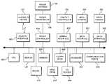
- the computer 102has an architecture similar to that of commercially available computers, and includes, at a minimum, a keyboard 812 , a pointing device 814 , random access memory (RAM) memory 804 , and central processor unit (CPU) 802 .
- the program instruction code implementing the HCE detection and tracking algorithmsis recorded onto standard computer readable medium and loaded into memory using a compact disk (CD) reader 806 or floppy disk drive 808 .
- the program instruction codemay be read directly from another computer via a standard communication port 818 available on most computers.
- the communication port 818may be a network connection enabling real-time collaboration between multiple HCE detection systems in the tracking and detection of human carried explosives.
- the computer 102has a radar controller 816 , which under control of the program instruction code triggers the radar and digitizes analog data received from the radar receiver portion of the radar transceiver. Furthermore, the computer 102 contains an interface 820 to the pan/tilt two-axis gimbal 104 that controls the horizontal and vertical positioning of the sensor platform 124 .
- Reliable radar-based detection of hidden HCE 112requires collecting several RF signature measurements of the subject 110 as it is moving within the radar field of regard 118 . Two reasons for this are collection geometry and scintillation. There is no guarantee that the explosive device 112 will be visible from the radar look direction given an arbitrary view of a subject 110 (i.e., if their back is toward the sensor 108 ). However, as the system tracks the subject 110 in the radar's field of regard, number of opportunities to gain favorable views of the HCE device 112 increases. Additionally, radar signatures of man-made objects and clutter can be highly variable due to the specular nature of returns from flat surfaces and the effect of constructive and destructive interference between coherent scatterers that lie in adjacent range bins.
- the radar assemblyis steered via commands to the gimbal controller 104 sent from the processor 102 so that the main-lobe of the radar beam 118 intersects the subject 110 and threat device 112 at a nominal standoff range R of one hundred meters.
- Energy scattered off of the subject 110 and threat device 112is collected at the antenna 108 , sent to the transceiver 106 , and converted to digital format by the processor 102 .
- Signal processing algorithms hosted on the processor 102are then used to automatically classify the return signal as “threat” or “non-threat.”
- the operator console function and user interfacemay consist of a standard display terminal 120 connected to computer 102 .
- the operator's console 120may be a portable or notebook computer having a display, keyboard and pointing device electrically connected to the computer 102 via a hardwired or wireless link.
- notificationssuch as a warning and indication and associated video signal may be sent to a remote field operator for viewing on a wireless handheld computer 122 over a wireless broadband communication link.
- FIG. 2is a flowchart representing the processing performed by the radar-only embodiment 100 of the System.
- Two modes of operationare available in the radar-only embodiment 100 : scan-mode 206 and track mode 204 .
- An operatorinitiates the system by selecting the desired operation mode 202 .
- scan mode 206the operator defines a scan pattern consisting of the azimuth and elevation extent of the radar field of regard, a sweep rate and a radar pulse repetition frequency (PRF).
- PRFradar pulse repetition frequency
- the scan pattern generator software within processor 102uses these parameters to generate a sequence of radar control signals that drive the radar beam position control module 208 and triggers the radar transceiver 106 .
- Track mode 204has two operator-selected modes: manual and automatic.
- Manual modeallows the operator to steer the radar beam using a joystick, trackball, keyboard or similar two-axis control input.
- manual track modethe operator has a further option as to the mode of radar triggering: either manual triggering or automatic triggering with a user selected PRF.
- automatic track modeerror signals are fed back from the radar and used in an adaptive scan pattern to maintain the beam on moving subjects.
- the userselects a desired radar PRF.
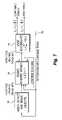
- FIG. 5illustrates a high-level block diagram of the sensor platform 124 with the radar transceiver 106 and radar antenna 108 mounted thereon.
- the antenna 108launches RF energy at the heading set by the beam position coordinates supplied by the scan-mode 206 or track-mode 204 controllers.
- the computer 102sends a trigger pulse 504 to the radar transmitter portion 502 of the radar transceiver 106 .
- the radar transmitter 502Upon receiving the trigger pulse 504 , the radar transmitter 502 generates a signal 506 that is upconverted to millimeter-wave frequencies and is transmitted through the radar antenna 108 .
- Backscattered radar returns 620 and 622are collected at the radar antenna 108 and sent to the radar receiver portion 508 of the radar transceiver 106 where they are downconverted to baseband and digitized. Digital radar signature data is then transmitted to the processor via digital data streams 510 and 512 to the processor 302 along with heading information extracted from the pan/tilt controller 104 .
- FIG. 6illustrates a representative high-level schematic of the radar assembly of transceiver 106 and antenna 108 .
- the radar transceiver 106incorporates a low-cost, commercially available FMCW (frequency-modulated continuous wave) radar, preferably operating at either a 77 GHz or 94 GHz center frequency, although a center frequency anywhere in the range from about 10 GHz to 110 GHz may be used.
- a trigger pulse 504is sent from the radar controller 820 .
- the trigger 504initiates a voltage-controlled oscillator (VCO) 602 that generates a frequency tone that is swept over a predefined range, f min to f max .
- the bandwidth, f max –f minis at least 500 MHz and preferably closer to 1 GHz.
- the output of a MMW (millimeter wave) local oscillator (LO) 604is collocated with the VCO 602 and both oscillators are protected 606 from temperature variations.
- the output of the LO 604is split into two parts using a power divider 608 .
- One half of the LO signalis sent through an isolator 610 and then mixed with the VCO output to upconvert the VCO signal to the MMW frequency band.
- the resulting signalis amplified by a high-gain MMW power amplifier 614 into a signal 506 , which is then transmitted through a Gaussian optic antenna 108 .
- the preferred embodimentuses a 12′′ diameter round antenna 616 with either a vertical or horizontally polarized feed element 630 .
- the RF signature collection 210 of the backscattered response from objects within the footprint of radar beam 118may be collected by using a common transmit and receive aperture, as in a mono-static radar system, or using separate transmit and receive apertures, as in a bi-static or multi-static configuration. Furthermore, a multi-element, phased-array antenna and space-time adaptive processing may be deployed. In the preferred embodiment, shown in FIG. 6 , the reflected radar signal is collected using a separate receive antenna 618 .
- the receive antenna 618is a single 12′′ diameter round Gaussian optic antenna and simultaneously collects both H and V polarizations.
- Dual polarization collectionis accomplished by inserting a polarizing grid 632 in the antenna 618 and splitting the V and H components of the return signal into two different feeds 620 and 622 .
- the two polarizationsare down-converted to baseband by being mixed with the same LO used to upconvert the transmitted VCO output.
- the other half 612 of the LO outputs after the first power divider 608is sent through a second power divider 624 , each of the two outputs is then sent through an isolator 626 or 628 before being mixed with the two received antenna signals 620 and 622 .
- the resulting signalsin this case, VV 510 and VH 512 , are sent to the radar controller 820 where they are converted into digital format via an analog-to-digital converter.
- the received radar signalsare then processed through two decision stages 212 and 216 .
- the first processing stageis detection 212 , in which the return signature is temporally adaptively filtered using a constant false-alarm rate (CFAR) technique to extract range bins where the scattered response energy exceeds the energy of spurious returns caused by clutter and receiver noise.
- Signals passing the CFAR testare then processed in a subsequent sequential hypothesis testing stage 216 to determine if they are consistent with returns from a threat device 112 . Signals that do not pass the CFAR threshold test are discarded 214 .
- CFARconstant false-alarm rate
- the processor 102can direct the operator, if in manual track mode, to hold the radar beam 118 on target until a sufficiently large number of radar samples has been collected to allow a reliable declaration of the threat status. In automatic track mode or scan mode the processor 102 automatically positions the beam 118 until sufficient data is received.
- Events that trigger a “threat” determinationmay then be used to initiate one or more mitigation responses 220 to be discussed later.
- Information available at the output of the radar-only embodiment 100 of the inventioninclude the estimated range and heading of the threat relative to the radar sensor, as well as the time at which the threat was detected. Additional characteristics, such as velocity vector, radar cross-section and other distinguishing signature features might also be provided to the operator as an aid to intercepting the threat 112 . As an example, one may consider continuing the radar track during the interception operation to provide real-time updates of position and heading information on detected threats 112 .
- the preferred embodimentincorporates a radar system having at least one transmit polarization and at least one receive polarization, i.e., at least a dual polarized system.
- the radar systemmay be alternately polarized, fully polarized, or use left or right circular polarization.
- the span of polarizationswill contain an orthogonal pair of either or both of transmit or receive polarizations.
- FIG. 3 and FIG. 8Billustrate an alternative embodiment of the HCE Detection System, which incorporates at least one video camera to improve threat determination and tracking capabilities of the System.
- the radar plus video embodiment 300includes a fixed, wide field of view (WFOV) video camera 306 that is aimed at the area under surveillance.
- WFOVwide field of view
- NFOVnarrow field of view
- the video outputs of the WFOV camera 306 and the NFOV camera 304are connected to one of several frame-grabbing interface products 830 and 832 known and available to those skilled in the art.
- the cameras 304 , 306may be any combination of black and white, color, infrared, Ladar, Lidar, imaging radar, hyperspectral, or multi-spectral cameras.
- a static background viewed by a stationary cameracan represent the background as patterns of light and dark in black/white intensity data from a B/W video camera, a LADAR/LIDAR sensor, or an imaging MMW radar sensor.
- Moving people in the scenecan then be detected by subtracting an average view of the static background intensities from each new frame of sensor data to find foreground pixels that represent a significant change from the background and therefore potential images of people moving in the foreground across the background.
- Foreground pixelscan be grouped and detected as people based on the size and shape of the group of pixels.
- a detected personcan then be tracked across subsequent frames by performing subtraction of the background intensity values.
- hyperspectral and multi-spectral video camerascan be used to detect humans by subtracting a representation of the background in color space where the data is represented by more than the three colors of a standard RBG video camera.
- range images in an angle-angle-range image from a LADAR, LIDAR, or MMW imaging radarcan be used to detect and track people by subtracting an average representation of the background in range-image space. Whether these alternative sensors have better detection and tracking performance than standard color video depends on the nature of the scene and the illumination. Improved detection and tracking performance can be obtained by using multiple types of imaging sensors in combination, but at an added expense is incurred by adding additional sensors to the system and additional processors to interpret the data from the additional sensors.
- FIG. 7is a high level flowchart illustrating the process by which the video system (either one or two cameras) 702 , maintains a track on the object until the radar system 704 has accumulated enough evidence to conclusively determine 706 the object's “threat” versus “non-threat” status.
- the radar systemcontinues to request track information from the video system.
- the radar systemcontinues to request track information from the video system.
- video signals from the WFOV video camera 306are operated upon by a video-tracking algorithm stored in program memory that is designed to detect and extract moving subjects from the WFOV camera 306 field of regard 308 .
- the heading of each detected moving subjectis estimated, and corresponding pan/tilt position commands are sent to the gimbal 104 .
- the processor 302sends a trigger to the radar transceiver 106 to initiate the transmission of one or more RF signals through the antenna 108 toward the subject 110 and any threat device 112 present on the subject 110 .
- Energy scattered off of the device 112 and subject 110is collected at the antenna 108 and forwarded to the transceiver 106 , which then transmits the data to the processor 302 where the data is processed using signal detection and classification algorithms.
- the signal detection and classification algorithmsclassify the reflected radar signal as being either “threat” or “non-threat”.
- the NFOV video 304refines the track-heading information extracted from within the field of view 308 of the WFOV video data to provide an estimate of the pose and posture of each detected subject 112 .
- Two modes of operationare available in the radar plus video embodiment 300 .
- video cued radarvideo motion detection and tracking algorithms implemented in software stored in memory in processor 302 are used to detect, segment and track moving subjects 112 in the video field of view. Track headings of subjects 112 detected in the video stream are used to control the radar beam position 118 and to trigger the radar in order to interrogate the threat status of each tracked object in the video field of view.
- the radaroperates in continuous scan mode with a scan pattern that covers the WFOV video camera 306 field of view 308 .
- Radar pulse returnsare tagged with the time and position of the pan/tilt head to allow registration of the radar data to the video sequence, both in time and look angle.
- FIG. 7illustrates the high level process by which the radar plus video embodiment 300 tracks and performs threat determination
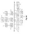
- FIG. 4illustrates in greater detail the interaction between the video and radar sensors, as well as the HCE threat detection process.
- the operation of the radar plus video embodiment 300can be broken down into four blocks A–D.
- Block Athe WFOV camera 306 collects video data and transmits the data to the processor 302 which applies motion detection and segmentation software implemented algorithms 406 to separate moving objects from stationary background.
- a two-sided composite hypothesis test 410is then applied to classify each detected moving object as being “human” or “other.”
- a database of constraints 408 on human characteristicsis utilized to classify the object type of each moving object detected.
- This database 408contains data elements including, but not limited to size, shape, thermal profile (if applicable for Infrared or multi-spectral cameras) and color (if applicable, for color cameras), and motion as an aid in classifying object type. Moving objects that are not consistent with human motion are discarded from further consideration 414 .
- Detected moving objects that have been classified as human-likeare then sent to the motion tracker module 412 along with the video stream collected by the WFOV camera 306 at step 404 .
- Information passed to the Tracker Module 412 by the Motion Detector Module 406includes the video frame number, a mask or region of interest delimiters that describe the location of the moving object in the video frame, and the ancillary statistics used in the initial hypothesis test 410 .
- the Motion Tracker Module 412generates and maintains a track for each object cued by the motion detector 406 . Tracks are maintained until the subject 110 leaves the field of view 310 of the WFOV camera 306 .
- a Threat Motion Analysis Module 416examines each track based upon a database 414 of stored characteristics, and determines the threat potential of the moving track.
- Database 414contains measurements or parameters that have been characterized as threat motions, either by an operator or from analysis of past threats. These characteristics may take the form of region constraints such as, “anybody who enters this demarked area is considered a threat”, or may consist of time and region constraints such as, “anybody who enters the demarked area at the wrong time”. Other threats could be someone moving toward the protected area at a higher rate of speed than other subjects in the area.
- An alternate strategywould have the Threat Motion Analysis Module 416 compare the motion statistics of new tracks to database 414 estimates of “normal” motion statistics within the surveillance area to determine if the motion of the tracked object represents an anomaly.
- a trackmay be classified as a “threat”, a “non-threat”, or “indeterminate”.
- the Threat Motion Analysis Module 416operates to detect dynamic or emerging threats in the presence of uncertainty by applying a sequential hypothesis test.
- a sequential hypothesis testis a statistic based test known to those skilled in the art of statistics. Unlike a normal hypothesis test which outputs a binary “yes/no” answer, a sequential hypothesis test allows a third answer, “don't know, collect more data.” The idea is that at each point in time, you collect additional information until you have enough information to make a decision about a given hypothesis. Preset or operator selected parameters within the sequential hypothesis test enable one to incorporate the cost of collecting more data into the optimization.
- the hypothesis test 416is sequentially reapplied with each new observation until a threat determination can be made or the subject has left the field of view.
- Threatening motionscould be defined as a subject with a motion vector toward the protected area and/or motion velocities that are markedly different from the average velocity of other subjects in the field of view 308 .
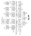
- Block Bincludes steps implementing the motion detection and tracking algorithm incorporated in processor 302 and is capable of simultaneously detecting and tracking multiple objects within the field of view 308 of the WFOV camera 306 .
- Motion tracks that are designated as potential threatsare forwarded from the Threat Motion Analysis Module 416 to the Track History Database 426 .
- Each trackis assigned a priority by a queuing algorithm that continuously compares the threat status of each track relative to other tracks in the database 426 .
- Several different approachescan be used to rank track priority.
- One approachis to rank tracks according to the range and velocity of each subject in the video field of view 308 . Subjects that are closer to the protected area and are closing at a faster rate are assigned the highest priority in the queue.
- Tracks associated with subjects that are exiting the field of view 308 of the WFOV camera 306are assigned a low priority and eventually dropped from the queue when the subject leaves the field of view.
- the Track Priority Queue and Scan Pattern Generator Module 422extracts heading and velocity estimates associated with the top track in the queue and commands the position controller 442 in Module C to steer the radar antenna 108 to point at the subject 110 .
- a trigger pulse 504is sent from the Track Priority Queue and Scan Pattern Generator Module 422 to the radar transceiver 106 to initiate a sequence of radar pulses illuminating the subject 110 and collect scattered radar signatures td determine the presence or absence of hidden threat objects 112 on the subject 110 .
- the nominal distance R within which the System 100 can detect a threat object 112is one hundred meters.
- the Position Control Module 442is configured to scan over a narrow sector of angles centered about the heading obtained from the Motion Tracker 412 .
- a sequence of radar returnsis collected at step 444 over the sector 118 .
- Each radar returnis collected, digitized and sent through a composite binary hypothesis test 448 to determine if the return is consistent with clutter or a human subject.
- a two-parameter, constant false-alarm (CFAR) algorithmis implemented in the software of processor 302 to test for human return versus clutter. Upon a determination of “clutter”, the radar is commanded to the next position in the designated sector.
- the CFAR testoperates on a collected RF signature of a target, the RF signature comprising a pair of complex-valued radar impulse response measurements, the co-polarized response, VV and the cross-polarized response, VH.
- 2the squared magnitude of each signal is computed and then summed to obtain an estimate of the total scattered energy as a function of range, i.e.,
- the corresponding quantitywould be referred to as the polarimetric span,
- 2the polarimetric span
- 2the two-parameter CFAR algorithm.
- the average signal energyis then computed over each window at each range shift and forms the ratio between the target and background averages. Ratios that fall below a predetermined threshold are classified as clutter and are dropped from further processing. Ratios that exceed the threshold are classified as “not clutter” and the corresponding radar measurements (VV and VH) are forwarded to the feature extraction module 454 .
- the optimal window sizes and clutter thresholdare a function of the radar system design and operating environment. Typically, one selects the target window to be approximately the same length as the range extent of a human subject.
- the background window sizeis typically chosen to be greater than or equal to the target window size, with the goal that it be smaller than any background inhomogeneities to avoid problems with estimating spatially-varying background statistics.
- rho(k,r)is then forwarded to the Associate Track module 424 where it is associated with one or more of the tracks in the Track History database 426 .
- the beamwidth of the radar and required accuracy required to hit a human-sized object at one hundred metersis equal to the width of the radar beam, which is about 0.5 degrees.
- a typical video tracking systemcan have a pointing error that is on the order of 2–3 degrees.
- the radar systemwill need to “reacquire” the target by performing a fine search about the heading provided by the video system. Once the target has been reacquired, the new signature is compared with previous signatures from that track and an accumulated statistic is calculated.
- Radar target reacquisitionis accomplished by scanning the radar beam 118 in azimuth along the error diameter of the cued video heading. At 50 m ⁇ 100 m ranges a 6′ tall person is between two and four radar beamwidths high. Therefore, by notionally scanning the radar at two or three different elevation angles, the System can separate upper body returns from legs and feet. At each elevation and azimuth location a radar pulse is collected and examined for the presence of a large-amplitude return along the range dimension by utilizing a cell-averaging, two-parameter, constant false-alarm rate (CFAR) detection algorithm.
- CFARconstant false-alarm rate
- the statisticis a local signal-to-noise (SNR) estimate and consists of the ratio between a local signal mean within a window centered at, divided by the average background level estimated from regions outside the window.
- SNRsignal-to-noise
- a classification algorithmis applied to separate threat signatures from normal chest response signatures.
- the evidence accrual module 428continuously polls each track and constructs a running detection statistic.
- Tracks declared “non-threat”are marked and maintained in the track history database 426 to allow for eliminating conflicts in the case of overlapping tracks or occlusions. Tracks for which there is insufficient evidence to declare “threat” or “non-threat” are maintained and the evidence accrual process 428 is continued until a definitive “threat” or “non-threat” declaration can be made 430 . Tracks declared “threat” are sent to the operator for intervention action as shown in Block D.
- thresholds T 1 and T 2are pre-determined. In the preferred embodiment, these thresholds are set by the operator and/or preset prior to deployment in order to achieve a desired detection versus false-alarm rate and to incorporate the cost of waiting to collect additional sample data.
- tau(j)also has an implicit time variable, “t” which represents the time-length of the track.
- Block Crepresents an enhancement to the video-radar cued embodiment which contemplates the use of an optional narrow field of view (NFOV) camera 304 that is co-boresighted with the radar beam 118 under command of the Position Control Module 442 .
- the NFOV camera 304collects high-resolution, zoomed-in video 310 of the object in the current track under interrogation.
- Video from the NFOV camera 304is processed to extract estimates of the subject body pose 450 .
- Pose and position estimates obtained from the NFOV camera 304are compared with the nominal heading information provided by the WFOV camera 306 .
- a correction vectoris generated and forwarded to the Position Control Module 442 and the position of the system is updated until the radar antenna 108 and NFOV 304 camera are aligned on the subject 110 .
- radar discriminantsare extracted from the radar signature 454 and combined with estimated pose information in the track history database 426 .
- Evidence accrualproceeds as before and three outcomes, “threat”, “non-threat” and “insufficient evidence” are possible.
- the corresponding threat declaration and track informationis passed at step 432 to the operator console 120 or to an optional wireless display device 122 .
- the information displayed on the operator console 120includes video data and associated radar statistical evidence. Based upon this data, an interdiction response can be initiated 434 .
- Forms of responsecan vary from automated triggering of a mitigation system, such as automated notification of first responders to more proactive activities, e.g., the aiming, arming and firing of a high-powered water cannon, 94 GHz. active denial radar, or similar non-lethal weapon.
- video informationcan be forwarded to first responders in the field to provide visual information to aid in identification and apprehension of the threat subject 110 .
- FIG. 9illustrates an application in which a plurality of HCE Detection Systems 904 A– 904 C collaborate to protect a specific site 910 .
- HCE Detection Systems 904 A– 904 Care networked together to form a collaborative detection and tracking system in order to achieve improved detection and false alarm rejection within an area under surveillance 902 .
- each System 904 A, 904 B and 904 Cmust be connected to a wideband network 930 .
- Threat mitigation devices 926in communication with and under control of the HCE Detection Systems operate to neutralize the threat 936 with a water cannon or active radar beam 922 .
- the network 930may be a hardwired or wireless network.
- Collaborative tracking and detectioncan be implemented in several ways.
- inter-computer communicationcoordinates the detection and tracking of potential targets 932 , 934 , and 936 by overlapping the radar field of regard 914 A– 914 B of each system 904 A– 904 B.
- the resulting measurements of the RF signaturesare combined to achieve simultaneous views of the field of regard from different look directions to increase the validity of the resultant threat determination.
- feature-based trackinghas been implemented to associate space-time coordinates and subject appearances as the threat passes through crowds having occluded regions.
- a second implementation of a collaborative network of HCE detection systemscan be used to expand the area of surveillance 902 by linking HCE radar systems 904 A– 904 C having non-overlapping fields of regards (not shown).
- Intersystem communicationwould coordinate the detection and tracking of potential human carried explosives over the union of the system wide fields of regard.
- Feature-based trackingwould associate space-time coordinates and appearances of subjects that move from one system field of regard to another system's field of regard.
- Decision processing and treat mitigation, performed centrally or decentralized at the individual system levelwould detect and classify the nature of the threat, and as heretofore disclosed, neutralize threat 936 as necessary.
- the radar systemis comprised of relatively low cost, commercially available components. Furthermore, the specific radar system deployed is not limited to the specific embodiments heretofore disclosed. In the preferred embodiment, the radar system is similar to radar-controlled automobile cruise control systems having a center frequency of about 77 GHz. and has a nominal range of approximately one hundred meters. Non-limiting, the radar system may operate at different or multiple frequencies, including the Ka-band, the W-band, UHF, and UWB frequencies. Furthermore, the radar system need not be comprised of a Frequency Modulated Continuous Wave (FMCW) real beam radar. An alternate radar system may consist of a linear chirp waveform.
- FMCWFrequency Modulated Continuous Wave
- an alternative to the previous embodiments 100 and 300in which the radar transmitter is collocated with the radar receiver, would entail a multi-static system in which one or more receivers is mounted apart from the one or more transmitters.
Landscapes
- Engineering & Computer Science (AREA)
- Radar, Positioning & Navigation (AREA)
- Remote Sensing (AREA)
- Physics & Mathematics (AREA)
- Computer Networks & Wireless Communication (AREA)
- General Physics & Mathematics (AREA)
- Electromagnetism (AREA)
- Radar Systems Or Details Thereof (AREA)
Abstract
Description
rho(k,r)=<|VV(k,r)|2>/<|VH(k,r)|2>,
over peak regions detected by the CFAR algorithm. In the preferred embodiment we use a local window that is the same size as the CFAR target window. The quantity rho(k,r) is then forwarded to the
phi(j)=Sum{pulsekin trackj}rho(k,r)
tau(j)=+1,phi(j)>
tau(j)=0,
tau(j)=−1, phi(j)<=
Claims (46)
Priority Applications (6)
| Application Number | Priority Date | Filing Date | Title |
|---|---|---|---|
| US10/970,465US6967612B1 (en) | 2004-10-22 | 2004-10-22 | System and method for standoff detection of human carried explosives |
| US11/665,929US7800527B2 (en) | 2004-10-22 | 2005-10-11 | System and method for standoff detection of human carried explosives |
| EP05858447.5AEP1810052B1 (en) | 2004-10-22 | 2005-10-11 | System and method for standoff detection of human carried explosives |
| PCT/US2005/036593WO2007011391A2 (en) | 2004-10-22 | 2005-10-11 | System and method for standoff detection of human carried exposives |
| IL182677AIL182677A (en) | 2004-10-22 | 2007-04-19 | System and method for standoff detection of human carried explosives |
| IL209225AIL209225A (en) | 2004-10-22 | 2010-11-10 | System and method for standoff detection of human carried explosives |
Applications Claiming Priority (1)
| Application Number | Priority Date | Filing Date | Title |
|---|---|---|---|
| US10/970,465US6967612B1 (en) | 2004-10-22 | 2004-10-22 | System and method for standoff detection of human carried explosives |
Publications (1)
| Publication Number | Publication Date |
|---|---|
| US6967612B1true US6967612B1 (en) | 2005-11-22 |
Family
ID=35344923
Family Applications (2)
| Application Number | Title | Priority Date | Filing Date |
|---|---|---|---|
| US10/970,465Expired - LifetimeUS6967612B1 (en) | 2004-10-22 | 2004-10-22 | System and method for standoff detection of human carried explosives |
| US11/665,929Active - Reinstated2026-05-21US7800527B2 (en) | 2004-10-22 | 2005-10-11 | System and method for standoff detection of human carried explosives |
Family Applications After (1)
| Application Number | Title | Priority Date | Filing Date |
|---|---|---|---|
| US11/665,929Active - Reinstated2026-05-21US7800527B2 (en) | 2004-10-22 | 2005-10-11 | System and method for standoff detection of human carried explosives |
Country Status (4)
| Country | Link |
|---|---|
| US (2) | US6967612B1 (en) |
| EP (1) | EP1810052B1 (en) |
| IL (2) | IL182677A (en) |
| WO (1) | WO2007011391A2 (en) |
Cited By (138)
| Publication number | Priority date | Publication date | Assignee | Title |
|---|---|---|---|---|
| US20050244978A1 (en)* | 2004-04-30 | 2005-11-03 | Onder Uluyol | Substance detection system |
| US20070035437A1 (en)* | 2005-05-31 | 2007-02-15 | L-3 Communications Cyterra Corporation | Computerized Tomography Using Radar |
| US20070194976A1 (en)* | 2006-02-17 | 2007-08-23 | Science, Engineering, And Technology Associates Corporation | Radar apparatus and processing method for detecting human carried explosive devices |
| US20070205937A1 (en)* | 2006-03-03 | 2007-09-06 | Realtronics Corporation | Apparatus and Method to Identify Targets Through Opaque Barriers |
| US20070210254A1 (en)* | 2005-11-15 | 2007-09-13 | University Of South Florida | Optical and Laser Differential Absorption Remote Detection of TATP Peroxide Based Explosives |
| WO2007044067A3 (en)* | 2005-04-06 | 2007-10-25 | Battelle Energy Alliance Llc | Method for imaging a concealed object |
| US20070286460A1 (en)* | 2006-06-08 | 2007-12-13 | General Electric Company | Standoff detection systems and methods |
| WO2007148327A3 (en)* | 2006-06-19 | 2008-02-07 | Ariel University Res And Dev C | Hand-held device and method for detecting concealed weapons and hidden objects |
| KR100832466B1 (en) | 2007-01-05 | 2008-05-26 | 동국대학교 산학협력단 | Manual millimeter wave hidden object detection device and method |
| US20080169961A1 (en)* | 2005-05-31 | 2008-07-17 | L-3 Communications Cyterra Corporation | Computerized Tomography Using Radar |
| US20080212742A1 (en)* | 2007-02-01 | 2008-09-04 | Hughes Ronald J | Personnel security screening system with enhanced privacy |
| WO2007082855A3 (en)* | 2006-01-19 | 2008-10-16 | Bosch Gmbh Robert | Measuring device comprising a signal unit |
| US20080316085A1 (en)* | 2007-06-22 | 2008-12-25 | Broadcom Corporation | Apparatus for position detection using multiple hcf transmissions |
| US7489334B1 (en)* | 2007-12-12 | 2009-02-10 | International Business Machines Corporation | Method and system for reducing the cost of sampling a moving image |
| US7492303B1 (en)* | 2006-05-09 | 2009-02-17 | Personnel Protection Technologies Llc | Methods and apparatus for detecting threats using radar |
| WO2009045236A1 (en) | 2007-05-17 | 2009-04-09 | Raytheon Company | Dual use rf directed energy weapon and imager |
| US20090102704A1 (en)* | 2007-09-20 | 2009-04-23 | Takashi Fujimura | Synthetic aperture radar, compact polarimetric sar processing method and program |
| US20090102602A1 (en)* | 2007-05-11 | 2009-04-23 | Robert Patrick Daly | System for the rapid deployment of a concealed object detection system |
| US20090135046A1 (en)* | 2007-11-28 | 2009-05-28 | Steele Daniel W | Radar system for manmade device detection and discrimination from clutter |
| US20090169053A1 (en)* | 2007-12-20 | 2009-07-02 | Canon Kabushiki Kaisha | Collaborative tracking |
| US20100039309A1 (en)* | 2006-09-07 | 2010-02-18 | Bae Systems Plc | Relating to scanners |
| US20100039311A1 (en)* | 2006-10-31 | 2010-02-18 | Woodington Walter G | System and Method for Generating an Alert Signal in a Detection System |
| KR100948104B1 (en) | 2006-12-26 | 2010-03-16 | 윤대영 | Dangerous Goods Detector |
| US20100117885A1 (en)* | 2005-02-15 | 2010-05-13 | Holbrook David S | Electromagnetic scanning imager |
| US20100140475A1 (en)* | 2007-03-30 | 2010-06-10 | Mervyn Keith Hobden | Detection device |
| EP2204670A1 (en)* | 2008-12-23 | 2010-07-07 | Sony Corporation | Adaptive sensing system |
| US20100182189A1 (en)* | 2006-08-17 | 2010-07-22 | Rheinmetall Waffe Munition Gmbh | Device and method for detecting non-linear electronic components or circuits especially of a booby trap or the like |
| US7768444B1 (en) | 2008-01-29 | 2010-08-03 | Rourk Christopher J | Weapon detection and elimination system |
| US20100225899A1 (en)* | 2005-12-23 | 2010-09-09 | Chemimage Corporation | Chemical Imaging Explosives (CHIMED) Optical Sensor using SWIR |
| US7826589B2 (en) | 2007-12-25 | 2010-11-02 | Rapiscan Systems, Inc. | Security system for screening people |
| US20100283662A1 (en)* | 2006-06-08 | 2010-11-11 | Fox Phillilp A | Method for surveillance to detect a land target |
| US20100283826A1 (en)* | 2007-09-01 | 2010-11-11 | Michael Andrew Henshaw | Audiovisual terminal |
| WO2011033264A1 (en) | 2009-09-17 | 2011-03-24 | Manchester Metropolitan University | Detection of objects |
| EP2322949A1 (en)* | 2009-11-14 | 2011-05-18 | EADS Deutschland GmbH | Method and device for monitoring target objects |
| WO2011080737A1 (en) | 2009-12-29 | 2011-07-07 | Israel Aerospace Industries Ltd. | A system and method for detecting concealed explosives and weapons |
| US20110181300A1 (en)* | 2008-03-18 | 2011-07-28 | Nicholas Bowring | Remote Detection and Measurement of Objects |
| US8003949B2 (en) | 2007-11-01 | 2011-08-23 | Rapiscan Systems, Inc. | Multiple screen detection systems |
| US20110205367A1 (en)* | 2010-02-23 | 2011-08-25 | Brown Kenneth W | MMW Enhanced Infrared Concealed Object Detection with Closed-Loop Control of Illumination Energy |
| US20110237446A1 (en)* | 2006-06-09 | 2011-09-29 | Chemlmage Corporation | Detection of Pathogenic Microorganisms Using Fused Raman, SWIR and LIBS Sensor Data |
| US8054454B2 (en) | 2005-07-14 | 2011-11-08 | Chemimage Corporation | Time and space resolved standoff hyperspectral IED explosives LIDAR detector |
| US8199996B2 (en) | 2007-06-21 | 2012-06-12 | Rapiscan Systems, Inc. | Systems and methods for improving directed people screening |
| US8232860B2 (en) | 2005-10-21 | 2012-07-31 | Honeywell International Inc. | RFID reader for facility access control and authorization |
| US20120242544A1 (en)* | 2011-03-17 | 2012-09-27 | Uchicago Argonne Llc | Radar detection of radiation-induced ionization in air |
| WO2012135477A1 (en)* | 2011-03-29 | 2012-10-04 | Battelle Memorial Institute | Development of a contrast phantom for active millimeter wave imaging systems |
| WO2012140587A2 (en) | 2011-04-15 | 2012-10-18 | Ariel-University Research And Development Company, Ltd. | Passive millimeter-wave detector |
| US8351350B2 (en) | 2007-05-28 | 2013-01-08 | Honeywell International Inc. | Systems and methods for configuring access control devices |
| US8379193B2 (en) | 2008-08-27 | 2013-02-19 | Chemimage Corporation | SWIR targeted agile raman (STAR) system for on-the-move detection of emplace explosives |
| US20130076913A1 (en)* | 2011-09-28 | 2013-03-28 | Xerox Corporation | System and method for object identification and tracking |
| EP2505996A4 (en)* | 2009-11-26 | 2013-06-26 | Apstec Systems Ltd | Method for remotely inspecting a target in a monitored area |
| EP2505995A4 (en)* | 2009-11-26 | 2013-06-26 | Apstec Systems Ltd | METHOD FOR DETERMINING THE DIELECTRIC PERMITTIVITY OF A DIELECTRIC OBJECT |
| US8485722B1 (en) | 2009-10-14 | 2013-07-16 | Raytheon Company | Subsurface temperature measurement system |
| US20130222172A1 (en)* | 2012-02-28 | 2013-08-29 | L-3 Communications Cyterra Corporation | Determining penetrability of a barrier |
| US8576982B2 (en) | 2008-02-01 | 2013-11-05 | Rapiscan Systems, Inc. | Personnel screening system |
| US8576989B2 (en) | 2010-03-14 | 2013-11-05 | Rapiscan Systems, Inc. | Beam forming apparatus |
| US8582089B2 (en) | 2006-06-09 | 2013-11-12 | Chemimage Corporation | System and method for combined raman, SWIR and LIBS detection |
| US8598982B2 (en) | 2007-05-28 | 2013-12-03 | Honeywell International Inc. | Systems and methods for commissioning access control devices |
| US20140035777A1 (en)* | 2012-08-06 | 2014-02-06 | Hyundai Motor Company | Method and system for producing classifier for recognizing obstacle |
| US8654922B2 (en) | 2009-11-18 | 2014-02-18 | Rapiscan Systems, Inc. | X-ray-based system and methods for inspecting a person's shoes for aviation security threats |
| US20140070111A1 (en)* | 2012-08-17 | 2014-03-13 | Northeastern University | Signal processing methods and systems for explosive detection and identification using electromagnetic radiation |
| US8707414B2 (en) | 2010-01-07 | 2014-04-22 | Honeywell International Inc. | Systems and methods for location aware access control management |
| US8743358B2 (en) | 2011-11-10 | 2014-06-03 | Chemimage Corporation | System and method for safer detection of unknown materials using dual polarized hyperspectral imaging and Raman spectroscopy |
| US20140168008A1 (en)* | 2012-12-19 | 2014-06-19 | Sony Corporation | Method for displaying an active radar image and handheld screening device |
| US8787725B2 (en) | 2010-11-11 | 2014-07-22 | Honeywell International Inc. | Systems and methods for managing video data |
| WO2014120289A1 (en)* | 2012-10-10 | 2014-08-07 | Raytheon Company | Detection of concealed object on a body using radio frequency signatures on frequencies and polarizations |
| CN103984036A (en)* | 2013-02-08 | 2014-08-13 | 索尼公司 | Screening method for operating a plurality of screening sensors, and screening system |
| US20140240511A1 (en)* | 2013-02-25 | 2014-08-28 | Xerox Corporation | Automatically focusing a spectral imaging system onto an object in a scene |
| US8823581B2 (en)* | 2006-12-06 | 2014-09-02 | Radical Development Holding S.A. | System and method for detecting dangerous objects and substances |
| EP2749909A3 (en)* | 2012-12-27 | 2014-09-03 | Nuctech Company Limited | Human body security inspection apparatus and method |
| US8842035B2 (en)* | 2010-04-08 | 2014-09-23 | L-3 Communications Security And Detection Systems, Inc. | Sensor head |
| WO2014151965A1 (en) | 2013-03-15 | 2014-09-25 | Kirill Mostov | Multi-sensor surveillance system for monitoring a space and detection of objects |
| US8854029B2 (en) | 2007-10-24 | 2014-10-07 | Radical Development Holding S.A. | System and method for space control and remote monitoring |
| US8878931B2 (en) | 2009-03-04 | 2014-11-04 | Honeywell International Inc. | Systems and methods for managing video data |
| US8924325B1 (en)* | 2011-02-08 | 2014-12-30 | Lockheed Martin Corporation | Computerized target hostility determination and countermeasure |
| US20150025738A1 (en)* | 2013-07-22 | 2015-01-22 | GM Global Technology Operations LLC | Methods and apparatus for automatic climate control in a vehicle based on clothing insulative factor |
| US8995619B2 (en) | 2010-03-14 | 2015-03-31 | Rapiscan Systems, Inc. | Personnel screening system |
| US8994934B1 (en) | 2010-11-10 | 2015-03-31 | Chemimage Corporation | System and method for eye safe detection of unknown targets |
| US9019070B2 (en) | 2009-03-19 | 2015-04-28 | Honeywell International Inc. | Systems and methods for managing access control devices |
| US9052290B2 (en) | 2012-10-15 | 2015-06-09 | Chemimage Corporation | SWIR targeted agile raman system for detection of unknown materials using dual polarization |
| US9103714B2 (en) | 2009-10-06 | 2015-08-11 | Chemimage Corporation | System and methods for explosives detection using SWIR |
| US20150241552A1 (en)* | 2014-02-26 | 2015-08-27 | Farrokh Mohamadi | Wafer scale sensor ultra-wideband array for tissue diagnosis |
| US9134404B2 (en) | 2012-11-30 | 2015-09-15 | Industrial Technology Research Institute | Electronic device and method for sensing active state of object |
| WO2015156928A1 (en)* | 2014-04-11 | 2015-10-15 | Aoptix Technologies, Inc. | Aligning transceiver systems of a data transmission network |
| US9229102B1 (en)* | 2009-12-18 | 2016-01-05 | L-3 Communications Security And Detection Systems, Inc. | Detection of movable objects |
| US20160019427A1 (en)* | 2013-03-11 | 2016-01-21 | Michael Scott Martin | Video surveillence system for detecting firearms |
| US9262896B1 (en) | 2005-01-28 | 2016-02-16 | Kirsen Technologies, Llc | Transportation security system and associated methods |
| US9280365B2 (en) | 2009-12-17 | 2016-03-08 | Honeywell International Inc. | Systems and methods for managing configuration data at disconnected remote devices |
| US9285325B2 (en) | 2007-02-01 | 2016-03-15 | Rapiscan Systems, Inc. | Personnel screening system |
| US9344684B2 (en) | 2011-08-05 | 2016-05-17 | Honeywell International Inc. | Systems and methods configured to enable content sharing between client terminals of a digital video management system |
| US20160178747A1 (en)* | 2014-06-30 | 2016-06-23 | Unique Solutions Design Ltd. | Handheld multi-sensor system for sizing irregular objects |
| US20160223646A1 (en)* | 2011-04-13 | 2016-08-04 | Raytheon Company | Enhanced detection and automatic signature extraction of radar resonance reflections in above and below-ground man-made objects |
| EP1850121A3 (en)* | 2006-04-28 | 2016-10-05 | Saima Sicurezza s.p.a. | Portable device for the detection of concealed objects using microwaves with two polarisations perpendicular to each other |
| CN106093089A (en)* | 2016-08-05 | 2016-11-09 | 同方威视技术股份有限公司 | Rays safety detection apparatus and method |
| WO2017037201A1 (en)* | 2015-09-03 | 2017-03-09 | Uniqueradar Sweden Ab | Radar-based detection system |
| US9671493B1 (en)* | 2014-09-19 | 2017-06-06 | Hrl Laboratories, Llc | Automated scheduling of radar-cued camera system for optimizing visual inspection (detection) of radar targets |
| US9704313B2 (en) | 2008-09-30 | 2017-07-11 | Honeywell International Inc. | Systems and methods for interacting with access control devices |
| US20170249461A1 (en)* | 2016-02-26 | 2017-08-31 | Cylance Inc. | Retention and accessibility of data characterizing events on an endpoint computer |
| EP3071998A4 (en)* | 2013-11-19 | 2017-10-18 | Apstec Systems USA LLC | Active microwave device and detection method |
| US9877659B2 (en) | 2012-11-30 | 2018-01-30 | Industrial Technology Research Institute | Sensing system and method for physiology measurements |
| US9894261B2 (en) | 2011-06-24 | 2018-02-13 | Honeywell International Inc. | Systems and methods for presenting digital video management system information via a user-customizable hierarchical tree interface |
| US9891314B2 (en) | 2014-03-07 | 2018-02-13 | Rapiscan Systems, Inc. | Ultra wide band detectors |
| WO2018087237A1 (en)* | 2016-11-10 | 2018-05-17 | Deutsches Zentrum für Luft- und Raumfahrt e.V. | Detection method for chemical substances, detection apparatus, feed-through apparatus |
| US10038872B2 (en) | 2011-08-05 | 2018-07-31 | Honeywell International Inc. | Systems and methods for managing video data |
| US10134254B2 (en) | 2014-11-25 | 2018-11-20 | Rapiscan Systems, Inc. | Intelligent security management system |
| US10209387B2 (en)* | 2014-09-19 | 2019-02-19 | Kabushiki Kaisha Toshiba | Screening device |
| US20190195989A1 (en)* | 2017-04-21 | 2019-06-27 | Tlc Millimeter Wave Products, Inc. | Millimeter wave advanced threat detection system network |
| US10345431B1 (en)* | 2015-06-09 | 2019-07-09 | Baron Services, Inc. | Dual polarization radar systems and methods |
| US10362273B2 (en) | 2011-08-05 | 2019-07-23 | Honeywell International Inc. | Systems and methods for managing video data |
| WO2019215454A1 (en) | 2018-05-10 | 2019-11-14 | Radio Physics Solutions Limited | Improvements in or relating to threat classification |
| US10523903B2 (en) | 2013-10-30 | 2019-12-31 | Honeywell International Inc. | Computer implemented systems frameworks and methods configured for enabling review of incident data |
| US10699012B2 (en) | 2017-01-11 | 2020-06-30 | Cylance Inc. | Endpoint detection and response utilizing machine learning |
| US10720300B2 (en) | 2016-09-30 | 2020-07-21 | American Science And Engineering, Inc. | X-ray source for 2D scanning beam imaging |
| US10772511B2 (en)* | 2018-05-16 | 2020-09-15 | Qualcomm Incorporated | Motion sensor using cross coupling |
| WO2020161703A3 (en)* | 2019-02-06 | 2020-09-17 | Essence Security International (E.S.I.) Ltd. | Radar location system and method |
| US10819714B2 (en) | 2017-04-26 | 2020-10-27 | Cylance Inc. | Endpoint detection and response system with endpoint-based artifact storage |
| US20210096239A1 (en)* | 2018-04-02 | 2021-04-01 | Panasonic Corporation | Intrusion detection system and intrusion detection method |
| US11002827B2 (en)* | 2019-05-21 | 2021-05-11 | Motorola Solutions, Inc. | System and method for collaborating between vehicular 360 degree threat detection appliances |
| US11022511B2 (en) | 2018-04-18 | 2021-06-01 | Aron Kain | Sensor commonality platform using multi-discipline adaptable sensors for customizable applications |
| US11055837B2 (en)* | 2019-03-29 | 2021-07-06 | Avigilon Corporation | Human profile and anomaly detection |
| US11150326B2 (en)* | 2018-09-17 | 2021-10-19 | Cubtek Inc. | Radar system with angle error determination function and method thereof |
| US20210364629A1 (en)* | 2018-05-10 | 2021-11-25 | Radio Physics Solutions Limited | Improvements in or relating to threat classification |
| US11199612B2 (en)* | 2017-04-28 | 2021-12-14 | Shenzhen Victooth Terahertz Technology Co., Ltd. | Direct wave suppression method and system for microwave imaging system |
| US11280898B2 (en) | 2014-03-07 | 2022-03-22 | Rapiscan Systems, Inc. | Radar-based baggage and parcel inspection systems |
| US20220163658A1 (en)* | 2020-11-26 | 2022-05-26 | Kabushiki Kaisha Toshiba | System and method |
| US20220216899A1 (en)* | 2019-05-08 | 2022-07-07 | Raytheon Bbn Technologies Corp. | Apparatus and method for detection of cyber tampering, physical tampering, and changes in performance of electronic devices |
| US20220377242A1 (en)* | 2021-05-24 | 2022-11-24 | Anduril Industries Inc. | Auto-focus tracking for remote flying targets |
| US11592522B1 (en)* | 2021-09-17 | 2023-02-28 | Aptiv Technologies Limited | Method and radar system for determining road conditions |
| US11606492B2 (en) | 2021-05-24 | 2023-03-14 | Anduril Industries, Inc. | Auto-focus acquisition for remote flying targets |
| IL264696B2 (en)* | 2019-02-06 | 2023-06-01 | Essence Security International Esi Ltd | Radar location system and method |
| US20230237889A1 (en)* | 2020-07-12 | 2023-07-27 | Essence Security International (E.S.I.) Ltd | Detecting an object in an environment |
| US20240088957A1 (en)* | 2022-09-13 | 2024-03-14 | Qualcomm Incorporated | Beamforming for backscatter radio |
| CN117890999A (en)* | 2024-03-15 | 2024-04-16 | 中国民用航空飞行学院 | Unmanned aerial vehicle lightning emission control method and device, electronic equipment and storage medium |
| US12248062B1 (en) | 2024-07-03 | 2025-03-11 | Quantum Ip, Llc | Enhanced material detection and frequency sweep analysis of controlled substances via digital signal processing |
| US12360234B1 (en)* | 2024-07-03 | 2025-07-15 | Quantump Ip, Llc | RF-based material identification systems and methods |
| US12372480B1 (en) | 2024-07-08 | 2025-07-29 | Quantum Ip, Llc | RF-based special material detection system with secure multi-dimensional authentication |
| US12379439B1 (en) | 2024-07-08 | 2025-08-05 | Quantum Ip, Llc | RF material detection device with smart scanning multiple axis gimbal integrated with haptics |
| US12386037B1 (en) | 2024-07-03 | 2025-08-12 | Quantum Ip, Llc | RF-based detection device for material identification using a smart frequency selection method |
| US12400532B2 (en) | 2020-07-12 | 2025-08-26 | Essence Security International (E.S.I.) Ltd. | Detecting an object in an environment |
| RU2847316C1 (en)* | 2024-06-26 | 2025-10-03 | Публичное Акционерное Общество "Научно-Производственное Объединение "Стрела" | Portable radar station for security of facilities with digital phased array antenna |
Families Citing this family (53)
| Publication number | Priority date | Publication date | Assignee | Title |
|---|---|---|---|---|
| US8097855B2 (en)* | 2005-11-30 | 2012-01-17 | Iscon Video Imaging, Inc. | Methods and systems for detecting concealed objects |
| US7657092B2 (en)* | 2005-11-30 | 2010-02-02 | Iscon Video Imaging, Inc. | Methods and systems for detecting concealed objects |
| US7664324B2 (en)* | 2005-11-30 | 2010-02-16 | Iscon Video Imaging, Inc. | Methods and systems for detecting concealed objects |
| WO2007090945A1 (en)* | 2006-02-07 | 2007-08-16 | France Telecom | Method of tracking the position of the head in real time in a video image stream |
| US9030320B2 (en)* | 2006-10-11 | 2015-05-12 | Thermal Matrix USA, Inc. | Real time threat detection system using integrated passive sensors |
| EP2223152A4 (en)* | 2007-11-20 | 2011-04-20 | Kirsen Technologies Corp | APPARATUS FOR DETECTION AND REMOTE MONITORING OF CONCEALED OBJECTS |
| IL187708A (en)* | 2007-11-28 | 2013-04-30 | Camero Tech Ltd | Through-the-obstacle radar system and method of operation |
| US20140300502A9 (en)* | 2007-12-18 | 2014-10-09 | Brijot Imaging Systems, Inc. | Millimeter Wave Energy Sensing Wand and Method |
| FR2925169B1 (en)* | 2007-12-18 | 2012-03-09 | Commissariat Energie Atomique | METHOD AND SYSTEM FOR ASSISTING ENVIRONMENTAL CHARACTERIZATION WITH ULTRA BROADBAND RADIO FREQUENCY SIGNALS. |
| US8947204B1 (en) | 2008-06-03 | 2015-02-03 | The Boeing Company | Optical interrogation and registration system |
| US7920049B2 (en)* | 2008-06-03 | 2011-04-05 | The Boeing Company | Registered 3-D optical thinfilm for remote identification |
| FR2933497B1 (en)* | 2008-07-03 | 2012-06-01 | Claude Goutelard | METHODS AND SYSTEMS FOR CODED EMISSION AND ANTENNA RECEPTION, IN PARTICULAR FOR RADAR |
| US8421017B2 (en)* | 2008-10-21 | 2013-04-16 | The United States Of America, As Represented By The Secretary Of The Navy | Analyte detection with infrared light |
| EP2376883B1 (en) | 2008-12-19 | 2018-02-28 | Radio Physics Solutions Ltd | A method for formation of radiometric images and an antenna for implementation of the method |
| US8111383B1 (en)* | 2010-01-15 | 2012-02-07 | Robert Foley | Portable laser surveillance method of a point on a target |
| IL204089A (en)* | 2010-02-21 | 2014-06-30 | Elbit Systems Ltd | Method and system for detection and tracking employing multi-view multi-spectral imaging |
| GB201015207D0 (en) | 2010-09-13 | 2010-10-27 | Radio Physics Solutions Ltd | Improvements in or relating to millimeter and sub-millimeter mave radar-radiometric imaging |
| US9157852B2 (en)* | 2010-09-17 | 2015-10-13 | Raytheon Company | Explosive material detection |
| US20120072127A1 (en)* | 2010-09-17 | 2012-03-22 | Raytheon Company | Explosive material detection |
| US8319682B2 (en)* | 2011-01-06 | 2012-11-27 | The Boeing Company | Method and apparatus for examining an object using electromagnetic millimeter-wave signal illumination |
| US9746988B2 (en)* | 2011-05-23 | 2017-08-29 | The Boeing Company | Multi-sensor surveillance system with a common operating picture |
| US9304190B2 (en)* | 2011-08-04 | 2016-04-05 | Apstec Systems Ltd | Method and system for unveiling hidden dielectric object |
| GB2496835B (en) | 2011-09-23 | 2015-12-30 | Radio Physics Solutions Ltd | Package for high frequency circuits |
| DE102011088439A1 (en)* | 2011-12-13 | 2013-06-13 | Robert Bosch Gmbh | Hand tool device with at least one locating device |
| US9122929B2 (en)* | 2012-08-17 | 2015-09-01 | Ge Aviation Systems, Llc | Method of identifying a tracked object for use in processing hyperspectral data |
| US11163050B2 (en) | 2013-08-09 | 2021-11-02 | The Board Of Trustees Of The Leland Stanford Junior University | Backscatter estimation using progressive self interference cancellation |
| US11209536B2 (en)* | 2014-05-02 | 2021-12-28 | The Board Of Trustees Of The Leland Stanford Junior University | Method and apparatus for tracking motion using radio frequency signals |
| JP6351497B2 (en)* | 2014-12-19 | 2018-07-04 | 三菱電機株式会社 | Target classifier |
| WO2017085755A1 (en)* | 2015-11-19 | 2017-05-26 | Nec Corporation | An advanced security system, an advanced security method and an advanced security program |
| KR101784611B1 (en)* | 2016-06-09 | 2017-11-06 | 재단법인대구경북과학기술원 | A human detecting apparatus and method using a lidar sensor and a radar sensor |
| US10338205B2 (en) | 2016-08-12 | 2019-07-02 | The Board Of Trustees Of The Leland Stanford Junior University | Backscatter communication among commodity WiFi radios |
| US10816658B2 (en) | 2016-09-07 | 2020-10-27 | OmniPreSense Corporation | Radar enabled weapon detection system |
| JP2020509618A (en) | 2016-10-25 | 2020-03-26 | ザ ボード オブ トラスティーズ オブ ザ レランド スタンフォード ジュニア ユニバーシティー | Backscatter ambient ISM band signal |
| US10317369B2 (en) | 2017-01-20 | 2019-06-11 | GTBM, Inc. | Acoustic frequency based system with crystalline transducer module and mass comparator for non-invasive detection of explosives and contraband |
| CN109696711B (en)* | 2017-10-20 | 2020-12-25 | 中国工程物理研究院电子工程研究所 | Convolutional neural network target detection and identification method based on polarization scattering characteristics |
| US11520028B2 (en)* | 2018-01-10 | 2022-12-06 | Richwave Technology Corp. | Occupancy detection using multiple antenna motion sensing |
| US10948587B1 (en)* | 2018-07-12 | 2021-03-16 | Adrien W. Boronse | Device for detecting explosive materials, or weapons or firearms, or knives or substances |
| US12039753B2 (en)* | 2018-08-29 | 2024-07-16 | Sony Corporation | Information processing apparatus and information processing method |
| EP3709000B1 (en) | 2019-03-14 | 2024-07-10 | Canon Kabushiki Kaisha | Processing system |
| US11715228B2 (en) | 2019-04-04 | 2023-08-01 | Battelle Memorial Institute | Imaging systems and related methods including radar imaging with moving arrays or moving targets |
| US11804076B2 (en) | 2019-10-02 | 2023-10-31 | University Of Iowa Research Foundation | System and method for the autonomous identification of physical abuse |
| US11243305B2 (en) | 2019-12-20 | 2022-02-08 | Motorola Solutions, Inc. | Method, system and computer program product for intelligent tracking and data transformation between interconnected sensor devices of mixed type |
| US12405367B2 (en) | 2020-06-25 | 2025-09-02 | Lassen Peak, Inc. | Systems and methods for noninvasive detection of impermissible objects |
| US12379485B2 (en) | 2020-06-25 | 2025-08-05 | Lassen Peak, Inc. | Systems and methods for handheld single chip submillimeter radars |
| US11231498B1 (en)* | 2020-07-21 | 2022-01-25 | International Business Machines Corporation | Concealed object detection |
| US20220107406A1 (en)* | 2020-10-05 | 2022-04-07 | Charles Partee | Combination optical and millimeter wavelength camera |
| US12099360B2 (en) | 2020-12-16 | 2024-09-24 | Lassen Peak, Inc. | Systems and methods for noninvasive aerial detection of impermissible objects |
| US11982734B2 (en) | 2021-01-06 | 2024-05-14 | Lassen Peak, Inc. | Systems and methods for multi-unit collaboration for noninvasive detection of concealed impermissible objects |
| US12000924B2 (en)* | 2021-01-06 | 2024-06-04 | Lassen Peak, Inc. | Systems and methods for noninvasive detection of impermissible objects |
| WO2022173451A1 (en)* | 2021-02-15 | 2022-08-18 | Boronse Adrien | A device for detecting explosive materials, or weapons or firearms, or knives or substances |
| US12050136B2 (en)* | 2021-03-16 | 2024-07-30 | Syght, Inc. | Calibration panel |
| US12436273B2 (en) | 2022-09-28 | 2025-10-07 | Deere & Company | Systems and methods for scheduling radar scan patterns in a vehicular radar system |
| CN116990883B (en)* | 2023-09-27 | 2023-12-15 | 北京中科太赫兹科技有限公司 | Remote person-carried dangerous object detection system based on multi-spectrum sensing fusion technology |
Citations (22)
| Publication number | Priority date | Publication date | Assignee | Title |
|---|---|---|---|---|
| US3707672A (en)* | 1971-06-02 | 1972-12-26 | Westinghouse Electric Corp | Weapon detector utilizing the pulsed field technique to detect weapons on the basis of weapons thickness |
| US3713156A (en)* | 1970-10-12 | 1973-01-23 | R Pothier | Surface and subsurface detection device |
| US4975968A (en)* | 1989-10-27 | 1990-12-04 | Spatial Dynamics, Ltd. | Timed dielectrometry surveillance method and apparatus |
| US5073782A (en)* | 1988-04-19 | 1991-12-17 | Millitech Corporation | Contraband detection system |
| US5081456A (en)* | 1987-04-13 | 1992-01-14 | Hitachi, Ltd. | Method of detecting unknown object and apparatus therefor |
| US5227800A (en)* | 1988-04-19 | 1993-07-13 | Millitech Corporation | Contraband detection system |
| US5455590A (en)* | 1991-08-30 | 1995-10-03 | Battelle Memorial Institute | Real-time holographic surveillance system |
| US5557283A (en)* | 1991-08-30 | 1996-09-17 | Sheen; David M. | Real-time wideband holographic surveillance system |
| US5592170A (en) | 1995-04-11 | 1997-01-07 | Jaycor | Radar system and method for detecting and discriminating targets from a safe distance |
| US5829437A (en) | 1994-07-01 | 1998-11-03 | Interstitial, Inc. | Microwave method and system to detect and locate cancers in heterogenous tissues |
| US5859609A (en)* | 1991-08-30 | 1999-01-12 | Battelle Memorial Institute | Real-time wideband cylindrical holographic surveillance system |
| US6057761A (en)* | 1997-01-21 | 2000-05-02 | Spatial Dynamics, Ltd. | Security system and method |
| US6243036B1 (en) | 1999-05-25 | 2001-06-05 | Macaleese Companies, Inc. | Signal processing for object detection system |
| US6359582B1 (en) | 1996-09-18 | 2002-03-19 | The Macaleese Companies, Inc. | Concealed weapons detection system |
| US6366232B1 (en) | 1998-10-15 | 2002-04-02 | Hilti Aktiengesellschaft | Method and sensor for detecting foreign bodies in a medium with a radar |
| US6480141B1 (en)* | 2001-03-13 | 2002-11-12 | Sandia Corporation | Detection of contraband using microwave radiation |
| US6507366B1 (en) | 1998-04-16 | 2003-01-14 | Samsung Electronics Co., Ltd. | Method and apparatus for automatically tracking a moving object |
| US6507309B2 (en)* | 2001-03-16 | 2003-01-14 | Battelle Memorial Institute | Interrogation of an object for dimensional and topographical information |
| US6720905B2 (en)* | 2002-08-28 | 2004-04-13 | Personnel Protection Technologies Llc | Methods and apparatus for detecting concealed weapons |
| US6765527B2 (en)* | 2000-09-27 | 2004-07-20 | The Johns Hopkins University | System and method of radar detection of non-linear interfaces |
| US6791487B1 (en)* | 2003-03-07 | 2004-09-14 | Honeywell International Inc. | Imaging methods and systems for concealed weapon detection |
| US6831590B1 (en)* | 2001-09-12 | 2004-12-14 | Cyterra Corporation | Concealed object detection |
Family Cites Families (7)
| Publication number | Priority date | Publication date | Assignee | Title |
|---|---|---|---|---|
| CA1169939A (en)* | 1981-04-16 | 1984-06-26 | Robert K. Harman | Intrusion detection system |
| US4595924A (en)* | 1981-10-06 | 1986-06-17 | General Dynamics Electronics | Intruder detection radar system and automatic nulling antenna array |
| US7167123B2 (en)* | 1999-05-25 | 2007-01-23 | Safe Zone Systems, Inc. | Object detection method and apparatus |
| GB2364390B (en)* | 2000-07-03 | 2004-11-17 | Yousri Mohammad Tah Haj-Yousef | A method and device for detecting and monitoring concealed bodies and objects |
| US6856272B2 (en)* | 2002-08-28 | 2005-02-15 | Personnel Protection Technoloties Llc | Methods and apparatus for detecting threats in different areas |
| US7148836B2 (en)* | 2004-03-05 | 2006-12-12 | The Regents Of The University Of California | Obstacle penetrating dynamic radar imaging system |
| US7154434B1 (en)* | 2005-09-12 | 2006-12-26 | The Boeing Company | Anti-personnel airborne radar application |
- 2004
- 2004-10-22USUS10/970,465patent/US6967612B1/ennot_activeExpired - Lifetime
- 2005
- 2005-10-11EPEP05858447.5Apatent/EP1810052B1/ennot_activeExpired - Lifetime
- 2005-10-11USUS11/665,929patent/US7800527B2/enactiveActive - Reinstated
- 2005-10-11WOPCT/US2005/036593patent/WO2007011391A2/enactiveApplication Filing
- 2007
- 2007-04-19ILIL182677Apatent/IL182677A/enactiveIP Right Grant
- 2010
- 2010-11-10ILIL209225Apatent/IL209225A/enactiveIP Right Grant
Patent Citations (25)
| Publication number | Priority date | Publication date | Assignee | Title |
|---|---|---|---|---|
| US3713156A (en)* | 1970-10-12 | 1973-01-23 | R Pothier | Surface and subsurface detection device |
| US3707672A (en)* | 1971-06-02 | 1972-12-26 | Westinghouse Electric Corp | Weapon detector utilizing the pulsed field technique to detect weapons on the basis of weapons thickness |
| US5081456A (en)* | 1987-04-13 | 1992-01-14 | Hitachi, Ltd. | Method of detecting unknown object and apparatus therefor |
| US5073782A (en)* | 1988-04-19 | 1991-12-17 | Millitech Corporation | Contraband detection system |
| US5227800A (en)* | 1988-04-19 | 1993-07-13 | Millitech Corporation | Contraband detection system |
| US4975968A (en)* | 1989-10-27 | 1990-12-04 | Spatial Dynamics, Ltd. | Timed dielectrometry surveillance method and apparatus |
| US5455590A (en)* | 1991-08-30 | 1995-10-03 | Battelle Memorial Institute | Real-time holographic surveillance system |
| US5557283A (en)* | 1991-08-30 | 1996-09-17 | Sheen; David M. | Real-time wideband holographic surveillance system |
| US5859609A (en)* | 1991-08-30 | 1999-01-12 | Battelle Memorial Institute | Real-time wideband cylindrical holographic surveillance system |
| US5829437A (en) | 1994-07-01 | 1998-11-03 | Interstitial, Inc. | Microwave method and system to detect and locate cancers in heterogenous tissues |
| US5592170A (en) | 1995-04-11 | 1997-01-07 | Jaycor | Radar system and method for detecting and discriminating targets from a safe distance |
| US6359582B1 (en) | 1996-09-18 | 2002-03-19 | The Macaleese Companies, Inc. | Concealed weapons detection system |
| US6057761A (en)* | 1997-01-21 | 2000-05-02 | Spatial Dynamics, Ltd. | Security system and method |
| US6507366B1 (en) | 1998-04-16 | 2003-01-14 | Samsung Electronics Co., Ltd. | Method and apparatus for automatically tracking a moving object |
| US6366232B1 (en) | 1998-10-15 | 2002-04-02 | Hilti Aktiengesellschaft | Method and sensor for detecting foreign bodies in a medium with a radar |
| US6243036B1 (en) | 1999-05-25 | 2001-06-05 | Macaleese Companies, Inc. | Signal processing for object detection system |
| US6342696B1 (en) | 1999-05-25 | 2002-01-29 | The Macaleese Companies, Inc. | Object detection method and apparatus employing polarized radiation |
| US6825456B2 (en)* | 1999-05-25 | 2004-11-30 | Safe Zone Systems, Inc. | Signal processing for object detection system |
| US6765527B2 (en)* | 2000-09-27 | 2004-07-20 | The Johns Hopkins University | System and method of radar detection of non-linear interfaces |
| US6480141B1 (en)* | 2001-03-13 | 2002-11-12 | Sandia Corporation | Detection of contraband using microwave radiation |
| US6507309B2 (en)* | 2001-03-16 | 2003-01-14 | Battelle Memorial Institute | Interrogation of an object for dimensional and topographical information |
| US6703964B2 (en)* | 2001-03-16 | 2004-03-09 | Battelle Memorial Institute | Interrogation of an object for dimensional and topographical information |
| US6831590B1 (en)* | 2001-09-12 | 2004-12-14 | Cyterra Corporation | Concealed object detection |
| US6720905B2 (en)* | 2002-08-28 | 2004-04-13 | Personnel Protection Technologies Llc | Methods and apparatus for detecting concealed weapons |
| US6791487B1 (en)* | 2003-03-07 | 2004-09-14 | Honeywell International Inc. | Imaging methods and systems for concealed weapon detection |
Non-Patent Citations (3)
| Title |
|---|
| Cory et al., "Radar-Based Intruder Detection for a Robotic Security System", SPIE Proc. 3525:Mobile Robots XIII and Intelligent Transportation Systems, Boston, MA, Nov. 1-5, 1008, pp. 62-72. |
| Everett, H.R., "Robotic Security Systems", IEEE Instrumentation & Measurement Magazine, Dec. 2003, pp. 30-34. |
| Pastore et al., "Mobile Robots for Outdoor Security Applications", American Nuclear Society, 8<SUP>th </SUP>International Topical Meeting on Robotics and Remote Systems (ANS'00), Pittsburg, PA, Apr. 25-29, 1999, pp. 1-16. |
Cited By (243)
| Publication number | Priority date | Publication date | Assignee | Title |
|---|---|---|---|---|
| US7531137B2 (en)* | 2004-04-30 | 2009-05-12 | Honeywell International Inc. | Substance detection system |
| US20050244978A1 (en)* | 2004-04-30 | 2005-11-03 | Onder Uluyol | Substance detection system |
| US9262896B1 (en) | 2005-01-28 | 2016-02-16 | Kirsen Technologies, Llc | Transportation security system and associated methods |
| US20100117885A1 (en)* | 2005-02-15 | 2010-05-13 | Holbrook David S | Electromagnetic scanning imager |
| US8253619B2 (en)* | 2005-02-15 | 2012-08-28 | Techtronic Power Tools Technology Limited | Electromagnetic scanning imager |
| WO2007044067A3 (en)* | 2005-04-06 | 2007-10-25 | Battelle Energy Alliance Llc | Method for imaging a concealed object |
| US7671784B2 (en) | 2005-05-31 | 2010-03-02 | L-3 Communications Cyterra Corporation | Computerized tomography using radar |
| US7312742B2 (en)* | 2005-05-31 | 2007-12-25 | L-3 Communications Security And Detection Systems, Inc. | Computerized tomography using radar |
| US20080169961A1 (en)* | 2005-05-31 | 2008-07-17 | L-3 Communications Cyterra Corporation | Computerized Tomography Using Radar |
| US20070035437A1 (en)* | 2005-05-31 | 2007-02-15 | L-3 Communications Cyterra Corporation | Computerized Tomography Using Radar |
| US8054454B2 (en) | 2005-07-14 | 2011-11-08 | Chemimage Corporation | Time and space resolved standoff hyperspectral IED explosives LIDAR detector |
| US8941464B2 (en) | 2005-10-21 | 2015-01-27 | Honeywell International Inc. | Authorization system and a method of authorization |
| US8232860B2 (en) | 2005-10-21 | 2012-07-31 | Honeywell International Inc. | RFID reader for facility access control and authorization |
| US7755041B2 (en)* | 2005-11-15 | 2010-07-13 | University Of South Florida | Optical and laser differential absorption remote detection of TATP peroxide based explosives |
| US20070210254A1 (en)* | 2005-11-15 | 2007-09-13 | University Of South Florida | Optical and Laser Differential Absorption Remote Detection of TATP Peroxide Based Explosives |
| US20100225899A1 (en)* | 2005-12-23 | 2010-09-09 | Chemimage Corporation | Chemical Imaging Explosives (CHIMED) Optical Sensor using SWIR |
| US8368880B2 (en) | 2005-12-23 | 2013-02-05 | Chemimage Corporation | Chemical imaging explosives (CHIMED) optical sensor using SWIR |
| WO2007082855A3 (en)* | 2006-01-19 | 2008-10-16 | Bosch Gmbh Robert | Measuring device comprising a signal unit |
| US20100156391A1 (en)* | 2006-01-19 | 2010-06-24 | Reiner Krapf | Measuring device |
| US8493076B2 (en) | 2006-01-19 | 2013-07-23 | Robert Bosch Gmbh | Measuring device |
| EP1994426A4 (en)* | 2006-02-17 | 2013-08-28 | Science Engineering And Technology Associates Co | Radar apparatus and processing method for detecting human carried explosive devices |
| US7304603B2 (en)* | 2006-02-17 | 2007-12-04 | Science, Engineering And Technology Associates Corporation | Radar apparatus and processing method for detecting human carried explosive devices |
| US20070194976A1 (en)* | 2006-02-17 | 2007-08-23 | Science, Engineering, And Technology Associates Corporation | Radar apparatus and processing method for detecting human carried explosive devices |
| JP2009526994A (en)* | 2006-02-17 | 2009-07-23 | サイエンス エンジニアリング アンド テクノロジー アソシエーツ コーポレーション | Radar equipment and processing method for detecting a human portable explosive device |
| US7920088B2 (en) | 2006-03-03 | 2011-04-05 | Scott Randall Thompson | Apparatus and method to identify targets through opaque barriers |
| US20070205937A1 (en)* | 2006-03-03 | 2007-09-06 | Realtronics Corporation | Apparatus and Method to Identify Targets Through Opaque Barriers |
| EP1850121A3 (en)* | 2006-04-28 | 2016-10-05 | Saima Sicurezza s.p.a. | Portable device for the detection of concealed objects using microwaves with two polarisations perpendicular to each other |
| US20090058710A1 (en)* | 2006-05-09 | 2009-03-05 | Levitan Arthur C | Methods and apparatus for detecting threats using radar |
| US7492303B1 (en)* | 2006-05-09 | 2009-02-17 | Personnel Protection Technologies Llc | Methods and apparatus for detecting threats using radar |
| US8330647B2 (en) | 2006-06-08 | 2012-12-11 | Vista Research, Inc. | Sensor suite and signal processing for border surveillance |
| US8026842B2 (en)* | 2006-06-08 | 2011-09-27 | Vista Research, Inc. | Method for surveillance to detect a land target |
| US9696409B2 (en)* | 2006-06-08 | 2017-07-04 | Vista Research, Inc. | Sensor suite and signal processing for border surveillance |
| WO2008073514A3 (en)* | 2006-06-08 | 2008-09-18 | Gen Electric | Standoff detection systems and methods |
| US7885429B2 (en)* | 2006-06-08 | 2011-02-08 | General Electric Company | Standoff detection systems and methods |
| US9030351B2 (en)* | 2006-06-08 | 2015-05-12 | Vista Research, Inc. | Sensor suite and signal processing for border surveillance |
| US20110001657A1 (en)* | 2006-06-08 | 2011-01-06 | Fox Philip A | Sensor suite and signal processing for border surveillance |
| US20070286460A1 (en)* | 2006-06-08 | 2007-12-13 | General Electric Company | Standoff detection systems and methods |
| US20100283662A1 (en)* | 2006-06-08 | 2010-11-11 | Fox Phillilp A | Method for surveillance to detect a land target |
| US20110237446A1 (en)* | 2006-06-09 | 2011-09-29 | Chemlmage Corporation | Detection of Pathogenic Microorganisms Using Fused Raman, SWIR and LIBS Sensor Data |
| US8582089B2 (en) | 2006-06-09 | 2013-11-12 | Chemimage Corporation | System and method for combined raman, SWIR and LIBS detection |
| WO2007148327A3 (en)* | 2006-06-19 | 2008-02-07 | Ariel University Res And Dev C | Hand-held device and method for detecting concealed weapons and hidden objects |
| US20090195435A1 (en)* | 2006-06-19 | 2009-08-06 | Ariel-University Research And Develoment Company Ltd. | Hand-held device and method for detecting concealed weapons and hidden objects |
| US7999723B2 (en)* | 2006-08-17 | 2011-08-16 | Rheinmetall Waffe Munition Gmbh | Device and method for detecting non-linear electronic components or circuits especially of a booby trap or the like |
| US20100182189A1 (en)* | 2006-08-17 | 2010-07-22 | Rheinmetall Waffe Munition Gmbh | Device and method for detecting non-linear electronic components or circuits especially of a booby trap or the like |
| US8674875B2 (en)* | 2006-09-07 | 2014-03-18 | Mbda Uk Limited | Scanners |
| US20100039309A1 (en)* | 2006-09-07 | 2010-02-18 | Bae Systems Plc | Relating to scanners |
| US8072370B2 (en)* | 2006-10-31 | 2011-12-06 | Valeo Radar Systems, Inc. | System and method for generating an alert signal in a detection system |
| US20100039311A1 (en)* | 2006-10-31 | 2010-02-18 | Woodington Walter G | System and Method for Generating an Alert Signal in a Detection System |
| US8823581B2 (en)* | 2006-12-06 | 2014-09-02 | Radical Development Holding S.A. | System and method for detecting dangerous objects and substances |
| KR100948104B1 (en) | 2006-12-26 | 2010-03-16 | 윤대영 | Dangerous Goods Detector |
| KR100832466B1 (en) | 2007-01-05 | 2008-05-26 | 동국대학교 산학협력단 | Manual millimeter wave hidden object detection device and method |
| US8135112B2 (en) | 2007-02-01 | 2012-03-13 | Rapiscan Systems, Inc. | Personnel security screening system with enhanced privacy |
| US9285325B2 (en) | 2007-02-01 | 2016-03-15 | Rapiscan Systems, Inc. | Personnel screening system |
| US9291741B2 (en) | 2007-02-01 | 2016-03-22 | Rapiscan Systems, Inc. | Personnel screening system |
| US7796733B2 (en) | 2007-02-01 | 2010-09-14 | Rapiscan Systems, Inc. | Personnel security screening system with enhanced privacy |
| US9182516B2 (en) | 2007-02-01 | 2015-11-10 | Rapiscan Systems, Inc. | Personnel screening system |
| US20080212742A1 (en)* | 2007-02-01 | 2008-09-04 | Hughes Ronald J | Personnel security screening system with enhanced privacy |
| US8536533B2 (en) | 2007-03-30 | 2013-09-17 | E2V Technologies (Uk) Limited | Detection device |
| US20100140475A1 (en)* | 2007-03-30 | 2010-06-10 | Mervyn Keith Hobden | Detection device |
| US20090102602A1 (en)* | 2007-05-11 | 2009-04-23 | Robert Patrick Daly | System for the rapid deployment of a concealed object detection system |
| EP2149057A4 (en)* | 2007-05-17 | 2011-05-25 | Raytheon Co | ARME AND RF IMAGER DIRECTED WITH DOUBLE ACTION |
| WO2009045236A1 (en) | 2007-05-17 | 2009-04-09 | Raytheon Company | Dual use rf directed energy weapon and imager |
| US8049173B1 (en) | 2007-05-17 | 2011-11-01 | Raytheon Company | Dual use RF directed energy weapon and imager |
| US8598982B2 (en) | 2007-05-28 | 2013-12-03 | Honeywell International Inc. | Systems and methods for commissioning access control devices |
| US8351350B2 (en) | 2007-05-28 | 2013-01-08 | Honeywell International Inc. | Systems and methods for configuring access control devices |
| US8199996B2 (en) | 2007-06-21 | 2012-06-12 | Rapiscan Systems, Inc. | Systems and methods for improving directed people screening |
| US8774362B2 (en) | 2007-06-21 | 2014-07-08 | Rapiscan Systems, Inc. | Systems and methods for improving directed people screening |
| US20080316085A1 (en)* | 2007-06-22 | 2008-12-25 | Broadcom Corporation | Apparatus for position detection using multiple hcf transmissions |
| US7973702B2 (en)* | 2007-06-22 | 2011-07-05 | Broadcom Corporation | Apparatus for position detection using multiple HCF transmissions |
| US20100283826A1 (en)* | 2007-09-01 | 2010-11-11 | Michael Andrew Henshaw | Audiovisual terminal |
| US7825847B2 (en)* | 2007-09-20 | 2010-11-02 | Nec Corporation | Synthetic aperture radar, compact polarimetric SAR processing method and program |
| US20090102704A1 (en)* | 2007-09-20 | 2009-04-23 | Takashi Fujimura | Synthetic aperture radar, compact polarimetric sar processing method and program |
| US8854029B2 (en) | 2007-10-24 | 2014-10-07 | Radical Development Holding S.A. | System and method for space control and remote monitoring |
| US8148693B2 (en) | 2007-11-01 | 2012-04-03 | Rapiscan Systems, Inc. | Multiple screen detection systems |
| US8401147B2 (en) | 2007-11-01 | 2013-03-19 | Rapiscan Systems, Inc. | Multiple screen detection systems |
| US8003949B2 (en) | 2007-11-01 | 2011-08-23 | Rapiscan Systems, Inc. | Multiple screen detection systems |
| US7830299B2 (en)* | 2007-11-28 | 2010-11-09 | Lockheed Martin Corporation | Radar system for manmade device detection and discrimination from clutter |
| US20090135046A1 (en)* | 2007-11-28 | 2009-05-28 | Steele Daniel W | Radar system for manmade device detection and discrimination from clutter |
| US20090154773A1 (en)* | 2007-12-12 | 2009-06-18 | International Business Machines Corporation | Method and system for reducing the cost of sampling a moving image |
| US7489334B1 (en)* | 2007-12-12 | 2009-02-10 | International Business Machines Corporation | Method and system for reducing the cost of sampling a moving image |
| US20090169053A1 (en)* | 2007-12-20 | 2009-07-02 | Canon Kabushiki Kaisha | Collaborative tracking |
| US8243989B2 (en)* | 2007-12-20 | 2012-08-14 | Canon Kabushiki Kaisha | Collaborative tracking |
| US20110096901A1 (en)* | 2007-12-25 | 2011-04-28 | Andreas Kotowski | Security System for Screening People |
| US7826589B2 (en) | 2007-12-25 | 2010-11-02 | Rapiscan Systems, Inc. | Security system for screening people |
| US7768444B1 (en) | 2008-01-29 | 2010-08-03 | Rourk Christopher J | Weapon detection and elimination system |
| US8576982B2 (en) | 2008-02-01 | 2013-11-05 | Rapiscan Systems, Inc. | Personnel screening system |
| US20110181300A1 (en)* | 2008-03-18 | 2011-07-28 | Nicholas Bowring | Remote Detection and Measurement of Objects |
| US10466351B2 (en) | 2008-03-18 | 2019-11-05 | Radio Physics Solutions Ltd. | Remote detection and measurement of objects |
| US9746552B2 (en) | 2008-03-18 | 2017-08-29 | Radio Physics Solutions Ltd. | Remote detection and measurement of objects |
| US9182481B2 (en) | 2008-03-18 | 2015-11-10 | Radio Physics Solutions Ltd. | Remote detection and measurement of objects |
| US11422252B2 (en) | 2008-03-18 | 2022-08-23 | Radio Physics Solutions Ltd. | Remote detection and measurement of objects |
| US8379193B2 (en) | 2008-08-27 | 2013-02-19 | Chemimage Corporation | SWIR targeted agile raman (STAR) system for on-the-move detection of emplace explosives |
| US9704313B2 (en) | 2008-09-30 | 2017-07-11 | Honeywell International Inc. | Systems and methods for interacting with access control devices |
| CN101793975A (en)* | 2008-12-23 | 2010-08-04 | 索尼株式会社 | Adaptive sensing system |
| US9645232B2 (en) | 2008-12-23 | 2017-05-09 | Sony Corporation | Adaptive sensing system |
| EP2204670A1 (en)* | 2008-12-23 | 2010-07-07 | Sony Corporation | Adaptive sensing system |
| US8723717B2 (en) | 2008-12-23 | 2014-05-13 | Sony Corporation | Adaptive sensing system |
| US8878931B2 (en) | 2009-03-04 | 2014-11-04 | Honeywell International Inc. | Systems and methods for managing video data |
| US9019070B2 (en) | 2009-03-19 | 2015-04-28 | Honeywell International Inc. | Systems and methods for managing access control devices |
| CN107390212A (en)* | 2009-09-17 | 2017-11-24 | 无线电物理解决方案有限公司 | Object detection |
| US10067226B2 (en) | 2009-09-17 | 2018-09-04 | Radio Physics Solutions, Ltd. | Detection of objects |
| US9335407B2 (en) | 2009-09-17 | 2016-05-10 | Radio Physics Solutions Ltd | Detection of objects |
| WO2011033264A1 (en) | 2009-09-17 | 2011-03-24 | Manchester Metropolitan University | Detection of objects |
| CN102713665A (en)* | 2009-09-17 | 2012-10-03 | 曼彻斯特城市大学 | object detection |
| US9103714B2 (en) | 2009-10-06 | 2015-08-11 | Chemimage Corporation | System and methods for explosives detection using SWIR |
| US8485722B1 (en) | 2009-10-14 | 2013-07-16 | Raytheon Company | Subsurface temperature measurement system |
| EP2322949A1 (en)* | 2009-11-14 | 2011-05-18 | EADS Deutschland GmbH | Method and device for monitoring target objects |
| DE102009053395B4 (en)* | 2009-11-14 | 2016-03-03 | Airbus Defence and Space GmbH | System and method for monitoring target objects |
| US8654922B2 (en) | 2009-11-18 | 2014-02-18 | Rapiscan Systems, Inc. | X-ray-based system and methods for inspecting a person's shoes for aviation security threats |
| EP2505995A4 (en)* | 2009-11-26 | 2013-06-26 | Apstec Systems Ltd | METHOD FOR DETERMINING THE DIELECTRIC PERMITTIVITY OF A DIELECTRIC OBJECT |
| EP2505996A4 (en)* | 2009-11-26 | 2013-06-26 | Apstec Systems Ltd | Method for remotely inspecting a target in a monitored area |
| EP2505995B1 (en) | 2009-11-26 | 2015-11-04 | APSTEC Systems Ltd | Method for determining the dielectric permittivity of a dielectric object |
| US9280365B2 (en) | 2009-12-17 | 2016-03-08 | Honeywell International Inc. | Systems and methods for managing configuration data at disconnected remote devices |
| US9229102B1 (en)* | 2009-12-18 | 2016-01-05 | L-3 Communications Security And Detection Systems, Inc. | Detection of movable objects |
| WO2011080737A1 (en) | 2009-12-29 | 2011-07-07 | Israel Aerospace Industries Ltd. | A system and method for detecting concealed explosives and weapons |
| US20120293355A1 (en)* | 2009-12-29 | 2012-11-22 | Israel Aerospace Industries Ltd. | System and method for detecting concealed explosives and weapons |
| US8988273B2 (en)* | 2009-12-29 | 2015-03-24 | Israel Aerospace Industries Ltd. | System and method for detecting concealed explosives and weapons |
| US8707414B2 (en) | 2010-01-07 | 2014-04-22 | Honeywell International Inc. | Systems and methods for location aware access control management |
| US8896701B2 (en) | 2010-02-23 | 2014-11-25 | Ratheon Company | Infrared concealed object detection enhanced with closed-loop control of illumination by.mmw energy |
| US20110205367A1 (en)* | 2010-02-23 | 2011-08-25 | Brown Kenneth W | MMW Enhanced Infrared Concealed Object Detection with Closed-Loop Control of Illumination Energy |
| US8995619B2 (en) | 2010-03-14 | 2015-03-31 | Rapiscan Systems, Inc. | Personnel screening system |
| US9058909B2 (en) | 2010-03-14 | 2015-06-16 | Rapiscan Systems, Inc. | Beam forming apparatus |
| US8576989B2 (en) | 2010-03-14 | 2013-11-05 | Rapiscan Systems, Inc. | Beam forming apparatus |
| US8842035B2 (en)* | 2010-04-08 | 2014-09-23 | L-3 Communications Security And Detection Systems, Inc. | Sensor head |
| US8994934B1 (en) | 2010-11-10 | 2015-03-31 | Chemimage Corporation | System and method for eye safe detection of unknown targets |
| US8787725B2 (en) | 2010-11-11 | 2014-07-22 | Honeywell International Inc. | Systems and methods for managing video data |
| US8924325B1 (en)* | 2011-02-08 | 2014-12-30 | Lockheed Martin Corporation | Computerized target hostility determination and countermeasure |
| US20120242544A1 (en)* | 2011-03-17 | 2012-09-27 | Uchicago Argonne Llc | Radar detection of radiation-induced ionization in air |
| US9086487B2 (en)* | 2011-03-17 | 2015-07-21 | Uchicago Argonne, Llc | Radar detection of radiation-induced ionization in air |
| WO2012135477A1 (en)* | 2011-03-29 | 2012-10-04 | Battelle Memorial Institute | Development of a contrast phantom for active millimeter wave imaging systems |
| US20160223646A1 (en)* | 2011-04-13 | 2016-08-04 | Raytheon Company | Enhanced detection and automatic signature extraction of radar resonance reflections in above and below-ground man-made objects |
| US9910134B2 (en)* | 2011-04-13 | 2018-03-06 | Raytheon Company | Enhanced detection and automatic signature extraction of radar resonance reflections in above and below-ground man-made objects |
| US10001559B2 (en)* | 2011-04-15 | 2018-06-19 | Ariel-University Research And Development Company Ltd. | Passive millimeter-wave detector |
| WO2012140587A2 (en) | 2011-04-15 | 2012-10-18 | Ariel-University Research And Development Company, Ltd. | Passive millimeter-wave detector |
| US9207317B2 (en)* | 2011-04-15 | 2015-12-08 | Ariel-University Research And Development Company Ltd. | Passive millimeter-wave detector |
| US20140253362A1 (en)* | 2011-04-15 | 2014-09-11 | Ariel-University Research And Development Company, Ltd. | Passive millimeter-wave detector |
| US9894261B2 (en) | 2011-06-24 | 2018-02-13 | Honeywell International Inc. | Systems and methods for presenting digital video management system information via a user-customizable hierarchical tree interface |
| US10863143B2 (en) | 2011-08-05 | 2020-12-08 | Honeywell International Inc. | Systems and methods for managing video data |
| US10362273B2 (en) | 2011-08-05 | 2019-07-23 | Honeywell International Inc. | Systems and methods for managing video data |
| US10038872B2 (en) | 2011-08-05 | 2018-07-31 | Honeywell International Inc. | Systems and methods for managing video data |
| US9344684B2 (en) | 2011-08-05 | 2016-05-17 | Honeywell International Inc. | Systems and methods configured to enable content sharing between client terminals of a digital video management system |
| US9025024B2 (en)* | 2011-09-28 | 2015-05-05 | Xerox Corporation | System and method for object identification and tracking |
| US20130076913A1 (en)* | 2011-09-28 | 2013-03-28 | Xerox Corporation | System and method for object identification and tracking |
| US8743358B2 (en) | 2011-11-10 | 2014-06-03 | Chemimage Corporation | System and method for safer detection of unknown materials using dual polarized hyperspectral imaging and Raman spectroscopy |
| US20130222172A1 (en)* | 2012-02-28 | 2013-08-29 | L-3 Communications Cyterra Corporation | Determining penetrability of a barrier |
| US9207320B2 (en)* | 2012-08-06 | 2015-12-08 | Hyundai Motor Company | Method and system for producing classifier for recognizing obstacle |
| US20140035777A1 (en)* | 2012-08-06 | 2014-02-06 | Hyundai Motor Company | Method and system for producing classifier for recognizing obstacle |
| US20140070111A1 (en)* | 2012-08-17 | 2014-03-13 | Northeastern University | Signal processing methods and systems for explosive detection and identification using electromagnetic radiation |
| US9575045B2 (en)* | 2012-08-17 | 2017-02-21 | Northeastern University | Signal processing methods and systems for explosive detection and identification using electromagnetic radiation |
| WO2014120289A1 (en)* | 2012-10-10 | 2014-08-07 | Raytheon Company | Detection of concealed object on a body using radio frequency signatures on frequencies and polarizations |
| US9903948B2 (en)* | 2012-10-10 | 2018-02-27 | Raytheon Company | Radar detection of a concealed object on a body |
| US20150276920A1 (en)* | 2012-10-10 | 2015-10-01 | Raytheon Company | Detection of concealed object on a body using radio frequency signatures on frequencies and polarizations |
| US9857462B2 (en)* | 2012-10-10 | 2018-01-02 | Raytheon Company | Detection of concealed object on a body using radio frequency signatures on frequencies and polarizations |
| US9052290B2 (en) | 2012-10-15 | 2015-06-09 | Chemimage Corporation | SWIR targeted agile raman system for detection of unknown materials using dual polarization |
| US9134404B2 (en) | 2012-11-30 | 2015-09-15 | Industrial Technology Research Institute | Electronic device and method for sensing active state of object |
| US9877659B2 (en) | 2012-11-30 | 2018-01-30 | Industrial Technology Research Institute | Sensing system and method for physiology measurements |
| US20140168008A1 (en)* | 2012-12-19 | 2014-06-19 | Sony Corporation | Method for displaying an active radar image and handheld screening device |
| US9223018B2 (en)* | 2012-12-19 | 2015-12-29 | Sony Corporation | Method for displaying an active radar image and handheld screening device |
| GB2509402B (en)* | 2012-12-27 | 2016-03-02 | Nuctech Co Ltd | Human body security inspection apparatus and method |
| EP2749909A3 (en)* | 2012-12-27 | 2014-09-03 | Nuctech Company Limited | Human body security inspection apparatus and method |
| CN103984036A (en)* | 2013-02-08 | 2014-08-13 | 索尼公司 | Screening method for operating a plurality of screening sensors, and screening system |
| US20140240511A1 (en)* | 2013-02-25 | 2014-08-28 | Xerox Corporation | Automatically focusing a spectral imaging system onto an object in a scene |
| US20160019427A1 (en)* | 2013-03-11 | 2016-01-21 | Michael Scott Martin | Video surveillence system for detecting firearms |
| EP2972474A4 (en)* | 2013-03-15 | 2016-10-26 | Kirill Mostov | MULTI-SENSOR MONITORING SYSTEM FOR MONITORING SPACE AND DETECTING OBJECTS |
| WO2014151965A1 (en) | 2013-03-15 | 2014-09-25 | Kirill Mostov | Multi-sensor surveillance system for monitoring a space and detection of objects |
| US20150025738A1 (en)* | 2013-07-22 | 2015-01-22 | GM Global Technology Operations LLC | Methods and apparatus for automatic climate control in a vehicle based on clothing insulative factor |
| US10523903B2 (en) | 2013-10-30 | 2019-12-31 | Honeywell International Inc. | Computer implemented systems frameworks and methods configured for enabling review of incident data |
| US11523088B2 (en) | 2013-10-30 | 2022-12-06 | Honeywell Interntional Inc. | Computer implemented systems frameworks and methods configured for enabling review of incident data |
| EP3071998A4 (en)* | 2013-11-19 | 2017-10-18 | Apstec Systems USA LLC | Active microwave device and detection method |
| US9372256B2 (en)* | 2014-02-26 | 2016-06-21 | Farrokh Mohamadi | Wafer scale sensor ultra-wideband array for tissue diagnosis |
| US20150241552A1 (en)* | 2014-02-26 | 2015-08-27 | Farrokh Mohamadi | Wafer scale sensor ultra-wideband array for tissue diagnosis |
| US11280898B2 (en) | 2014-03-07 | 2022-03-22 | Rapiscan Systems, Inc. | Radar-based baggage and parcel inspection systems |
| US9891314B2 (en) | 2014-03-07 | 2018-02-13 | Rapiscan Systems, Inc. | Ultra wide band detectors |
| US9319133B2 (en) | 2014-04-11 | 2016-04-19 | Aoptix Technologies, Inc. | Aligning transceiver systems of a data transmission network |
| WO2015156928A1 (en)* | 2014-04-11 | 2015-10-15 | Aoptix Technologies, Inc. | Aligning transceiver systems of a data transmission network |
| US20160178746A1 (en)* | 2014-06-30 | 2016-06-23 | Unique Solutions Design Ltd. | Handheld multi-sensor system for sizing irregular objects |
| US20160178747A1 (en)* | 2014-06-30 | 2016-06-23 | Unique Solutions Design Ltd. | Handheld multi-sensor system for sizing irregular objects |
| US9575172B2 (en)* | 2014-06-30 | 2017-02-21 | Bodidata, Inc. | Handheld multi-sensor system for sizing irregular objects |
| US10209387B2 (en)* | 2014-09-19 | 2019-02-19 | Kabushiki Kaisha Toshiba | Screening device |
| US9671493B1 (en)* | 2014-09-19 | 2017-06-06 | Hrl Laboratories, Llc | Automated scheduling of radar-cued camera system for optimizing visual inspection (detection) of radar targets |
| US10134254B2 (en) | 2014-11-25 | 2018-11-20 | Rapiscan Systems, Inc. | Intelligent security management system |
| US10713914B2 (en) | 2014-11-25 | 2020-07-14 | Rapiscan Systems, Inc. | Intelligent security management system |
| US10345431B1 (en)* | 2015-06-09 | 2019-07-09 | Baron Services, Inc. | Dual polarization radar systems and methods |
| WO2017037201A1 (en)* | 2015-09-03 | 2017-03-09 | Uniqueradar Sweden Ab | Radar-based detection system |
| US10354067B2 (en) | 2016-02-26 | 2019-07-16 | Cylance Inc. | Retention and accessibility of data characterizing events on an endpoint computer |
| US10354066B2 (en)* | 2016-02-26 | 2019-07-16 | Cylance Inc. | Retention and accessibility of data characterizing events on an endpoint computer |
| US11204996B2 (en) | 2016-02-26 | 2021-12-21 | Cylance Inc. | Retention and accessibility of data characterizing events on an endpoint computer |
| US20170249461A1 (en)* | 2016-02-26 | 2017-08-31 | Cylance Inc. | Retention and accessibility of data characterizing events on an endpoint computer |
| US11204997B2 (en)* | 2016-02-26 | 2021-12-21 | Cylance, Inc. | Retention and accessibility of data characterizing events on an endpoint computer |
| US10585052B2 (en) | 2016-08-05 | 2020-03-10 | Nuctech Company Limited | Security inspection apparatus and method |
| CN106093089B (en)* | 2016-08-05 | 2019-03-01 | 同方威视技术股份有限公司 | Rays safety detection apparatus and method |
| EP3279701A1 (en)* | 2016-08-05 | 2018-02-07 | Nuctech Company Limited | Security inspection apparatus and method |
| CN106093089A (en)* | 2016-08-05 | 2016-11-09 | 同方威视技术股份有限公司 | Rays safety detection apparatus and method |
| US10720300B2 (en) | 2016-09-30 | 2020-07-21 | American Science And Engineering, Inc. | X-ray source for 2D scanning beam imaging |
| WO2018087237A1 (en)* | 2016-11-10 | 2018-05-17 | Deutsches Zentrum für Luft- und Raumfahrt e.V. | Detection method for chemical substances, detection apparatus, feed-through apparatus |
| US10699012B2 (en) | 2017-01-11 | 2020-06-30 | Cylance Inc. | Endpoint detection and response utilizing machine learning |
| US11494490B2 (en) | 2017-01-11 | 2022-11-08 | Cylance Inc. | Endpoint detection and response utilizing machine learning |
| US20190195989A1 (en)* | 2017-04-21 | 2019-06-27 | Tlc Millimeter Wave Products, Inc. | Millimeter wave advanced threat detection system network |
| US20220026560A1 (en)* | 2017-04-21 | 2022-01-27 | Tlc Millimeter Wave Products, Inc. | Millimeter wave advanced threat detection system network |
| US10819714B2 (en) | 2017-04-26 | 2020-10-27 | Cylance Inc. | Endpoint detection and response system with endpoint-based artifact storage |
| US10944761B2 (en) | 2017-04-26 | 2021-03-09 | Cylance Inc. | Endpoint detection and response system event characterization data transfer |
| US11528282B2 (en) | 2017-04-26 | 2022-12-13 | Cylance Inc. | Endpoint detection and response system with endpoint-based artifact storage |
| US11199612B2 (en)* | 2017-04-28 | 2021-12-14 | Shenzhen Victooth Terahertz Technology Co., Ltd. | Direct wave suppression method and system for microwave imaging system |
| US20210096239A1 (en)* | 2018-04-02 | 2021-04-01 | Panasonic Corporation | Intrusion detection system and intrusion detection method |
| US11022511B2 (en) | 2018-04-18 | 2021-06-01 | Aron Kain | Sensor commonality platform using multi-discipline adaptable sensors for customizable applications |
| US20210364629A1 (en)* | 2018-05-10 | 2021-11-25 | Radio Physics Solutions Limited | Improvements in or relating to threat classification |
| WO2019215454A1 (en) | 2018-05-10 | 2019-11-14 | Radio Physics Solutions Limited | Improvements in or relating to threat classification |
| GB2588304B (en)* | 2018-05-10 | 2023-02-08 | Radio Physics Solutions Ltd | Improvements in or relating to threat classification |
| US10772511B2 (en)* | 2018-05-16 | 2020-09-15 | Qualcomm Incorporated | Motion sensor using cross coupling |
| US11150326B2 (en)* | 2018-09-17 | 2021-10-19 | Cubtek Inc. | Radar system with angle error determination function and method thereof |
| US11754697B2 (en)* | 2019-02-06 | 2023-09-12 | Essence Security International (E.S.I.) Ltd. | Radar location system and method |
| US20220283279A1 (en)* | 2019-02-06 | 2022-09-08 | Essence Security International (E.S.I.) Ltd. | Radar location system and method |
| WO2020161703A3 (en)* | 2019-02-06 | 2020-09-17 | Essence Security International (E.S.I.) Ltd. | Radar location system and method |
| US12105180B2 (en)* | 2019-02-06 | 2024-10-01 | Essence Security International (E.S.I.) Ltd. | Radar location system and method |
| IL264696B2 (en)* | 2019-02-06 | 2023-06-01 | Essence Security International Esi Ltd | Radar location system and method |
| US11055837B2 (en)* | 2019-03-29 | 2021-07-06 | Avigilon Corporation | Human profile and anomaly detection |
| US11621746B2 (en)* | 2019-05-08 | 2023-04-04 | Raytheon Bbn Technologies Corp. | Apparatus and method for detection of cyber tampering, physical tampering, and changes in performance of electronic devices |
| US20220216899A1 (en)* | 2019-05-08 | 2022-07-07 | Raytheon Bbn Technologies Corp. | Apparatus and method for detection of cyber tampering, physical tampering, and changes in performance of electronic devices |
| US11002827B2 (en)* | 2019-05-21 | 2021-05-11 | Motorola Solutions, Inc. | System and method for collaborating between vehicular 360 degree threat detection appliances |
| US12400532B2 (en) | 2020-07-12 | 2025-08-26 | Essence Security International (E.S.I.) Ltd. | Detecting an object in an environment |
| US20230237889A1 (en)* | 2020-07-12 | 2023-07-27 | Essence Security International (E.S.I.) Ltd | Detecting an object in an environment |
| US20220163658A1 (en)* | 2020-11-26 | 2022-05-26 | Kabushiki Kaisha Toshiba | System and method |
| US20220377242A1 (en)* | 2021-05-24 | 2022-11-24 | Anduril Industries Inc. | Auto-focus tracking for remote flying targets |
| US12096109B2 (en) | 2021-05-24 | 2024-09-17 | Anduril Industries, Inc. | Auto-focus acquisition for remote flying targets |
| US11611707B2 (en)* | 2021-05-24 | 2023-03-21 | Anduril Industries, Inc. | Auto-focus tracking for remote flying targets |
| WO2022250974A1 (en)* | 2021-05-24 | 2022-12-01 | Anduril Industries, Inc. | Auto-focus tracking for remote flying targets |
| US20230269477A1 (en)* | 2021-05-24 | 2023-08-24 | Anduril Industries, Inc. | Auto-focus tracking for remote flying targets |
| US11606492B2 (en) | 2021-05-24 | 2023-03-14 | Anduril Industries, Inc. | Auto-focus acquisition for remote flying targets |
| US12267593B2 (en)* | 2021-05-24 | 2025-04-01 | Anduril Industries, Inc. | Auto-focus tracking for remote flying targets |
| US11592522B1 (en)* | 2021-09-17 | 2023-02-28 | Aptiv Technologies Limited | Method and radar system for determining road conditions |
| US20230087328A1 (en)* | 2021-09-17 | 2023-03-23 | Aptiv Technologies Limited | Method and radar system for determining road conditions |
| CN115825956A (en)* | 2021-09-17 | 2023-03-21 | Aptiv技术有限公司 | Method and radar system for determining a road condition |
| CN115825956B (en)* | 2021-09-17 | 2023-12-29 | Aptiv技术有限公司 | Method and radar system for determining road conditions |
| US12323207B2 (en)* | 2022-09-13 | 2025-06-03 | Qualcomm Incorporated | Beamforming for backscatter radio |
| US20240088957A1 (en)* | 2022-09-13 | 2024-03-14 | Qualcomm Incorporated | Beamforming for backscatter radio |
| CN117890999A (en)* | 2024-03-15 | 2024-04-16 | 中国民用航空飞行学院 | Unmanned aerial vehicle lightning emission control method and device, electronic equipment and storage medium |
| CN117890999B (en)* | 2024-03-15 | 2024-05-31 | 中国民用航空飞行学院 | Unmanned aerial vehicle lightning emission control method and device, electronic equipment and storage medium |
| RU2847316C1 (en)* | 2024-06-26 | 2025-10-03 | Публичное Акционерное Общество "Научно-Производственное Объединение "Стрела" | Portable radar station for security of facilities with digital phased array antenna |
| US12248062B1 (en) | 2024-07-03 | 2025-03-11 | Quantum Ip, Llc | Enhanced material detection and frequency sweep analysis of controlled substances via digital signal processing |
| US12360234B1 (en)* | 2024-07-03 | 2025-07-15 | Quantump Ip, Llc | RF-based material identification systems and methods |
| US12386037B1 (en) | 2024-07-03 | 2025-08-12 | Quantum Ip, Llc | RF-based detection device for material identification using a smart frequency selection method |
| US12372480B1 (en) | 2024-07-08 | 2025-07-29 | Quantum Ip, Llc | RF-based special material detection system with secure multi-dimensional authentication |
| US12379439B1 (en) | 2024-07-08 | 2025-08-05 | Quantum Ip, Llc | RF material detection device with smart scanning multiple axis gimbal integrated with haptics |
Also Published As
| Publication number | Publication date |
|---|---|
| IL209225A0 (en) | 2011-01-31 |
| EP1810052A2 (en) | 2007-07-25 |
| IL209225A (en) | 2016-08-31 |
| WO2007011391A2 (en) | 2007-01-25 |
| US20080129581A1 (en) | 2008-06-05 |
| IL182677A0 (en) | 2007-09-20 |
| WO2007011391A3 (en) | 2007-04-19 |
| EP1810052B1 (en) | 2018-01-24 |
| US7800527B2 (en) | 2010-09-21 |
| IL182677A (en) | 2014-12-31 |
| EP1810052A4 (en) | 2011-03-23 |
Similar Documents
| Publication | Publication Date | Title |
|---|---|---|
| US6967612B1 (en) | System and method for standoff detection of human carried explosives | |
| US7492303B1 (en) | Methods and apparatus for detecting threats using radar | |
| KR100483897B1 (en) | Concealed weapons detection system | |
| US6720905B2 (en) | Methods and apparatus for detecting concealed weapons | |
| US7920088B2 (en) | Apparatus and method to identify targets through opaque barriers | |
| Ferris Jr et al. | Survey of current technologies for through-the-wall surveillance (TWS) | |
| US6856272B2 (en) | Methods and apparatus for detecting threats in different areas | |
| EP2519834B1 (en) | A system and method for detecting concealed explosives and weapons | |
| US20180067204A1 (en) | Radar enabled weapon detection system | |
| Poitevin et al. | Challenges in detecting UAS with radar | |
| Andrews et al. | Active millimeter wave sensor for standoff concealed threat detection | |
| Liang | Sense-through-wall human detection based on UWB radar sensors | |
| US20110084868A1 (en) | Variable range millimeter wave method and system | |
| Ritchie et al. | Micro UAV crime prevention: Can we help Princess Leia? | |
| US20080284636A1 (en) | Object detection method and apparatus | |
| Zohuri | Electronic countermeasure and electronic counter-countermeasure | |
| Bowring et al. | Development of a longer range standoff millimetre wave radar concealed threat detector | |
| Currie et al. | Imaging sensor fusion for concealed weapon detection | |
| Harmer et al. | Millimetre radar threat level evaluation (MiRTLE) at standoff ranges | |
| Felber et al. | Fusion of radar and ultrasound sensors for concealed weapons detection | |
| Falcone et al. | Active and passive radar sensors for airport security | |
| Lovberg et al. | Passive millimeter-wave imaging for concealed article detection | |
| Alsaedi et al. | Survy of Methods and Techniques for Metal Detection | |
| Taylor et al. | -The Camero, Inc., UWB Radar for Concealed Weapons Detection | |
| Bárbara | Calibration Techniques for a New Space Radar Cassegrain Antenna Pointing System |
Legal Events
| Date | Code | Title | Description |
|---|---|---|---|
| STCF | Information on status: patent grant | Free format text:PATENTED CASE | |
| AS | Assignment | Owner name:SCIENCE, ENGINEERING, AND TECHNOLOGY ASSOCIATES CO Free format text:ASSIGNMENT OF ASSIGNORS INTEREST;ASSIGNORS:GORMAN, JOHN D.;DOUGLASS, ROBERT J.;BURNS JR, THOMAS J.;REEL/FRAME:017946/0749 Effective date:20060221 | |
| FPAY | Fee payment | Year of fee payment:4 | |
| FEPP | Fee payment procedure | Free format text:PAT HOLDER NO LONGER CLAIMS SMALL ENTITY STATUS, ENTITY STATUS SET TO UNDISCOUNTED (ORIGINAL EVENT CODE: STOL); ENTITY STATUS OF PATENT OWNER: LARGE ENTITY | |
| REMI | Maintenance fee reminder mailed | ||
| FPAY | Fee payment | Year of fee payment:8 | |
| SULP | Surcharge for late payment | Year of fee payment:7 | |
| SULP | Surcharge for late payment | ||
| AS | Assignment | Owner name:LOCKER, LLC, CALIFORNIA Free format text:ASSIGNMENT OF ASSIGNORS INTEREST;ASSIGNOR:SCIENCE, ENGINEERING, AND TECHNOLOGY ASSOCIATES CORPORATION, ALSO KNOWN AS SET CORPORATION AND SET ASSOCIATES;REEL/FRAME:033443/0098 Effective date:20140509 | |
| REMI | Maintenance fee reminder mailed | ||
| FEPP | Fee payment procedure | Free format text:11.5 YR SURCHARGE- LATE PMT W/IN 6 MO, LARGE ENTITY (ORIGINAL EVENT CODE: M1556) | |
| MAFP | Maintenance fee payment | Free format text:PAYMENT OF MAINTENANCE FEE, 12TH YEAR, LARGE ENTITY (ORIGINAL EVENT CODE: M1553) Year of fee payment:12 | |
| AS | Assignment | Owner name:RAPISCAN LABORATORIES, INC., CALIFORNIA Free format text:ASSIGNMENT OF ASSIGNORS INTEREST;ASSIGNOR:LOCKER, LLC;REEL/FRAME:046097/0956 Effective date:20180614 |