US6966760B1 - Reciprocating fluid pump employing reversing polarity motor - Google Patents
Reciprocating fluid pump employing reversing polarity motorDownload PDFInfo
- Publication number
- US6966760B1 US6966760B1US09/528,766US52876600AUS6966760B1US 6966760 B1US6966760 B1US 6966760B1US 52876600 AUS52876600 AUS 52876600AUS 6966760 B1US6966760 B1US 6966760B1
- Authority
- US
- United States
- Prior art keywords
- pump
- fuel
- movable member
- reciprocating
- assembly
- Prior art date
- Legal status (The legal status is an assumption and is not a legal conclusion. Google has not performed a legal analysis and makes no representation as to the accuracy of the status listed.)
- Expired - Lifetime
Links
- 239000012530fluidSubstances0.000titleclaimsabstractdescription45
- 239000000446fuelSubstances0.000claimsabstractdescription92
- 238000002347injectionMethods0.000claimsabstractdescription37
- 239000007924injectionSubstances0.000claimsabstractdescription37
- 238000002485combustion reactionMethods0.000claimsabstractdescription31
- 230000005291magnetic effectEffects0.000claimsabstractdescription21
- 230000000712assemblyEffects0.000claimsdescription9
- 238000000429assemblyMethods0.000claimsdescription9
- 238000004891communicationMethods0.000claimsdescription3
- 238000004804windingMethods0.000claims6
- 238000005086pumpingMethods0.000abstractdescription20
- 230000005672electromagnetic fieldEffects0.000abstractdescription6
- 230000004907fluxEffects0.000abstractdescription5
- 125000004122cyclic groupChemical group0.000abstract1
- 238000000034methodMethods0.000description14
- 238000006073displacement reactionMethods0.000description6
- 239000007788liquidSubstances0.000description6
- 238000013461designMethods0.000description4
- 230000003993interactionEffects0.000description4
- 230000036961partial effectEffects0.000description4
- 230000009471actionEffects0.000description3
- 230000002093peripheral effectEffects0.000description3
- 239000012071phaseSubstances0.000description3
- 230000004044responseEffects0.000description3
- 239000003302ferromagnetic materialSubstances0.000description2
- 230000006870functionEffects0.000description2
- 239000000463materialSubstances0.000description2
- 238000012986modificationMethods0.000description2
- 230000004048modificationEffects0.000description2
- 230000002829reductive effectEffects0.000description2
- 230000001105regulatory effectEffects0.000description2
- 230000006978adaptationEffects0.000description1
- 230000002411adverseEffects0.000description1
- 230000004075alterationEffects0.000description1
- 230000005465channelingEffects0.000description1
- 230000006835compressionEffects0.000description1
- 238000007906compressionMethods0.000description1
- 238000001816coolingMethods0.000description1
- 230000000694effectsEffects0.000description1
- 239000007792gaseous phaseSubstances0.000description1
- 238000010438heat treatmentMethods0.000description1
- 238000009434installationMethods0.000description1
- 230000000670limiting effectEffects0.000description1
- 239000007791liquid phaseSubstances0.000description1
- 239000000696magnetic materialSubstances0.000description1
- 238000004519manufacturing processMethods0.000description1
- 238000005192partitionMethods0.000description1
- 238000012545processingMethods0.000description1
- 230000003134recirculating effectEffects0.000description1
- 230000009467reductionEffects0.000description1
- 230000002441reversible effectEffects0.000description1
- 230000002000scavenging effectEffects0.000description1
- 239000007921spraySubstances0.000description1
Images


Classifications
- F—MECHANICAL ENGINEERING; LIGHTING; HEATING; WEAPONS; BLASTING
- F04—POSITIVE - DISPLACEMENT MACHINES FOR LIQUIDS; PUMPS FOR LIQUIDS OR ELASTIC FLUIDS
- F04B—POSITIVE-DISPLACEMENT MACHINES FOR LIQUIDS; PUMPS
- F04B17/00—Pumps characterised by combination with, or adaptation to, specific driving engines or motors
- F04B17/03—Pumps characterised by combination with, or adaptation to, specific driving engines or motors driven by electric motors
- F04B17/04—Pumps characterised by combination with, or adaptation to, specific driving engines or motors driven by electric motors using solenoids
- F04B17/042—Pumps characterised by combination with, or adaptation to, specific driving engines or motors driven by electric motors using solenoids the solenoid motor being separated from the fluid flow
- F—MECHANICAL ENGINEERING; LIGHTING; HEATING; WEAPONS; BLASTING
- F04—POSITIVE - DISPLACEMENT MACHINES FOR LIQUIDS; PUMPS FOR LIQUIDS OR ELASTIC FLUIDS
- F04B—POSITIVE-DISPLACEMENT MACHINES FOR LIQUIDS; PUMPS
- F04B17/00—Pumps characterised by combination with, or adaptation to, specific driving engines or motors
- F04B17/03—Pumps characterised by combination with, or adaptation to, specific driving engines or motors driven by electric motors
- F04B17/04—Pumps characterised by combination with, or adaptation to, specific driving engines or motors driven by electric motors using solenoids
- F04B17/046—Pumps characterised by combination with, or adaptation to, specific driving engines or motors driven by electric motors using solenoids the fluid flowing through the moving part of the motor
Definitions
- the present inventionrelates generally to the field of electrically-driven reciprocating pumps. More particularly, the invention relates to a pump which is particularly well suited for use as a fuel pump, driven by a solenoid assembly employing a permanent magnet and a solenoid coil to produce pressure variations in a pump section and thereby to draw into and express from the pump section a fluid, such as a fuel being pumped. The invention also relates to a fuel injector assembly employing such a pump.
- a wide range of pumpshave been developed for displacing fluids under pressure produced by electrical drives.
- fuelis displaced via a reciprocating pump assembly which is driven by electric current supplied from a source, typically a vehicle electrical system.
- a reluctance gap coilis positioned in a solenoid housing, and an armature is mounted movably within the housing and secured to a guide tube.
- the solenoid coilmay be energized to force displacement of the armature toward the reluctance gap in a magnetic circuit defined around the solenoid coil.
- the guide tubemoves with the armature, entering and withdrawing from a pump section. By reciprocal movement of the guide tube into and out of the pump section, fluid is drawn into the pump section and expressed from the pump section during operation.
- the armature and guide tubeare typically returned to their original position under the influence of one or more biasing springs.
- an additional biasing springmay be used to return the injection nozzle to its original position.
- the combination of biasing springsUpon interruption of energizing current to the coil, the combination of biasing springs then forces the entire movable assembly to its original position.
- the cycle time of the resulting deviceis the sum of the time required for the pressurization stroke during energization of the solenoid coil, and the time required for returning the armature and guide to the original position for the next pressure stroke.
- cycle timescan be extremely rapid. Moreover, repeatability and precision in beginning and ending of pump stroke cycles can be important in optimizing the performance of the engine under varying operating conditions. While the cycle time may be reduced by providing stronger springs for returning the reciprocating assembly to the initial position, such springs have the adverse effect of opposing forces exerted on the reciprocating assembly by energization of the solenoid. Such forces must therefore be overcome by correspondingly increased forces created during energization of the solenoid. At some point, however, increased current levels required for such forces become undesirable due to the limits of the electrical components, and additional heating produced by electrical losses.
- the present inventionprovides a novel technique for pumping fluids in a reciprocating pump arrangement designed to respond to these needs.
- the techniqueis particularly well suited for use in fuel delivery systems, such as in direct, in chamber fuel injection.
- the techniqueis in no way limited to such applications, and may be employed in a wide range of technical fields.
- the pumping drive systemoffers significant advantages over known arrangements, including a reduction in cycle times, controllability of initial positions of a reciprocating assembly, controllability of stroke of a reciprocating assembly, and thereby of displacement per cycle, and so forth.
- the techniqueis based upon a drive system employing at least one permanent magnet and at least one coil assembly.
- the coil assemblyis energized cyclically to produce reciprocating motion of a drive member, which may be coupled directly to the coil.
- the drive membermay extend into a pumping section, and cause variations in fluid pressure by intrusion into and withdrawal from the pumping section during its reciprocal movement.
- Valves, such as check valves, within the pumping sectionare actuated by the variations in pressure, permitting fluid to be drawn into the pumping section and expressed therefrom.
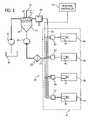
- FIG. 1is a diagrammatical representation of a series of fluid pump assemblies applied to inject fuel into an internal combustion engine
- FIG. 4is a partial sectional view of an alternative embodiment of a drive section of a fluid pump in accordance with aspects of the present technique.
- FIG. 5is a partial sectional view of a further alternative embodiment of a pump drive section.
- a fuel injection system 10is illustrated diagrammatically, including a series of pumps for displacing fuel under pressure in an internal combustion engine 12 .
- the fluid pumps of the present techniquemay be employed in a wide variety of settings, they are particularly well suited to fuel injection systems in which relatively small quantities of fuel are pressurized cyclically to inject the fuel into combustion chambers of an engine as a function of the engine demands.
- the pumpsmay be employed with individual combustion chambers as in the illustrated embodiment, or may be associated in various ways to pressurize quantities of fuel, as in a fuel rail, feed manifold, and so forth.
- the present pumping techniquemay be employed in settings other than fuel injection, such as for displacing fluids under pressure in response to electrical control signals used to energize coils of a drive assembly, as described below.
- the fuel injection system 10includes a fuel reservoir 14 , such as a tank for containing a reserve of liquid fuel.
- a first pump 16draws the fuel from the reservoir, and delivers the fuel to a separator 18 . While the system may function adequately without a separator 18 , in the illustrated embodiment, separator 18 serves to insure that the fuel injection system downstream receives liquid fuel, as opposed to mixed phase fuel.
- a second pump 20draws the liquid fuel from separator 18 and delivers the fuel, through a cooler 22 , to a feed or inlet manifold 24 .
- Cooler 22may be any suitable type of fluid cooler, including both air and liquid heater exchangers, radiators, and so forth.
- Fuel from the feed manifold 24is available for injection into combustion chambers of engine 12 , as described more fully below.
- a return manifold 26is provided for recirculating fluid not injected into the combustion chambers of the engine.
- a pressure regulating valve 28is placed in series in the return manifold line 26 for maintaining a desired pressure within the return manifold. Fluid returned via the pressure regulating valve 28 is recirculated into the separator 18 where the fuel collects in liquid phase as illustrated at reference numeral 30 .
- Gaseous phase components of the fueldesignated by referenced numeral 32 in FIG. 1 , may rise from the fuel surface and, depending upon the level of liquid fuel within the separator, may be allowed to escape via a float valve 34 .
- a vent 36is provided for permitting the escape of gaseous components, such as for repressurization, recirculation, and so forth.
- Engine 12includes a series of combustion chambers or cylinders 38 for driving an output shaft (not shown) in rotation.
- pistons(not shown) are driven in a reciprocating fashion within each combustion chamber in response to ignition of fuel within the combustion chamber.
- the stroke of the piston within the chamberwill permit fresh air for subsequent combustion cycles to be admitted into the chamber, while scavenging combustion products from the chamber.
- the present embodimentemploys a straightforward two-stroke engine design, the pumps in accordance with the present technique may be adapted for a wide variety of applications and engine-designs, including other than two-stroke engines and cycles.
- Injection controller 44which will typically include a programmed microprocessor or other digital processing circuitry, and memory for storing a routine employed in providing control signals to the pumps, applies energizing signals to the pumps to cause their reciprocation in any one of a wide variety of manners as described more fully below.
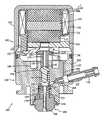
- the pump and nozzle assembly 100 illustrated in FIG. 2is particularly well suited to application in an internal combustion engine, as in the components illustrated in FIG. 1 as pumps 40 .
- a nozzle assemblyis installed directly at an outlet of the pump section, such that the pump 40 of FIG. 1 and the nozzle 42 are incorporated into a single assembly or unit.
- the pump illustrated in FIG. 2may be separated from the nozzle, such as for application of fluid under pressure to a manifold, fuel rail, or other downstream component.
- drive section 102includes a housing 106 designed to sealingly receive the drive section components and support them during operation.
- the drive sectionfurther includes at least one permanent magnet 108 , and in the preferred embodiment illustrated, a pair of permanent magnets 108 and 110 .
- the permanent magnetsare separated from one another and disposed adjacent to a central core 112 made of a material which is capable of conducting magnetic flux, such as a ferromagnetic material.
- a coil bobbin 114is disposed about permanent magnets 108 and 110 , and core 112 . While magnets 108 and 110 , and core 112 are fixedly supported within housing 106 , bobbin 114 is free to slide longitudinally with respect to these components.
- bobbin 114is centered around core 112 , and may slide with respect to the core upwardly and downwardly in the orientation shown in FIG. 2 .
- a coil 116is wound within bobbin 114 and free ends of the coil are coupled to leads L for receiving energizing control signals, such as from an injection controller 44 , as illustrated in FIG. 1 .
- Bobbin 114further includes an extension 118 which protrudes from the region of the bobbin in which the coil is installed for driving the pump section as described below. Although one such extension is illustrated in FIG. 2 , it should be understood that the bobbin may comprise a series of extensions, such as 2, 3 or 4 extensions arranged circumferentially around the bobbin.
- drive section 102includes a support or partition 120 which aids in supporting the permanent magnets and core, and in separating the drive section from the pump section. It should be noted, however, that in the illustrated embodiment, the inner volume of the drive section, including the volume in which the coil is disposed, may be flooded with fluid during operation, such as for cooling purposes.
- a drive member 122is secured to bobbin 114 via extension 118 .
- drive member 122forms a generally cup-shaped plate having a central aperture for the passage of fluid.
- the cup shape of the drive memberaids in centering a plunger 124 which is disposed within a concave portion of the drive member.
- Plunger 124preferably has a longitudinal central opening or aperture 126 extending from its base to a head region 128 designed to contact and bear against drive member 122 .
- a biasing spring 130is compressed between the head region 128 and a lower component of the pump section to maintain the plunger 124 , the drive member 122 , and bobbin and coil assembly in an upward or biased position.
- plunger 124 , drive member 122 , extension 118 , bobbin 114 , and coil 116thus form a reciprocating assembly which is driven in an oscillating motion during operation of the device as described more fully below.
- the drive section 102 and pump section 104are designed to interface with one another, preferably to permit separate manufacturing and installation of these components as subassemblies, and to permit their servicing as needed.
- housing 106 of drive section 102terminates in a skirt 132 which is secured about a peripheral wall 134 of pump section 104 .
- the drive and pump sectionsare preferably sealed, such as via a soft seal 136 .
- these housingsmay be interfaced via threaded engagement, or any other suitable technique.
- Pump section 104forms a central aperture 138 designed to receive plunger 124 .
- Aperture 138also serves to guide the plunger in its reciprocating motion during operation of the device.
- An annular recess 140surrounds aperture 138 and receives biasing spring 130 , maintaining the biasing spring in a centralized position to further aid in guiding plunger 124 .
- head region 128includes a peripheral groove or recess 142 which receives biasing spring 130 at an end thereof opposite recess 140 .
- valve member 144is positioned in pump section 104 below plunger 124 .
- valve member 144forms a separable extension of plunger 124 during operation, but is spaced from plunger 124 by a gap 146 when plunger 124 is retracted as illustrated in FIG. 2 .
- Gap 146is formed by limiting the upward movement of valve member 144 , such as by a restriction in the peripheral wall defining aperture 138 . Grooves (not shown) may be provided at this location to allow for the flow of fluid around valve member 144 when the plunger is advanced to its retracted position.
- gap 146permits the entire reciprocating assembly, including plunger 124 , to gain momentum during a pumping stroke before contacting valve member 144 to compress and expel fluid from the pump section.
- Valve member 144is positioned within a pump chamber 148 .
- Pump chamber 148receives fluid from an inlet 150 .
- Inlet 150thus includes a fluid passage 152 through which fluid, such as pressurized fuel, is introduced into the pump chamber.
- a check valve assemblyindicated generally at reference numeral 154 , is provided between passage 152 and pump chamber 148 , and is closed by the pressure created within pump chamber 148 during a pumping stroke of the device.
- a fluid passage 156is provided between inlet passage 152 and the volume within which the drive section components are disposed. Passage 156 may permit the free flow of fluid into the drive section, to maintain the drive section components bathed in fluid.
- a fluid outlet(not shown) may similarly be in fluid communication with the internal volume of the drive section, to permit the recirculation of fluid from the drive section.
- Valve 144is maintained in a biased position toward gap 146 by a biasing spring 158 .
- biasing spring 158is compressed between an upper portion of the valve member and a retaining ring 160 .
- a nozzle assembly 162may be incorporated directly into a lower portion of the pump assembly.
- an exemplary nozzleincludes a nozzle body 164 which is sealingly fitted to the pump section.
- a poppet 166is positioned within a central aperture formed in the valve body, and is sealed against the valve body in a retracted position shown in FIG. 2 .
- a retaining member 168is provided at an upper end of poppet 166 . Retaining member 168 contacts a biasing spring 170 which is compressed between the nozzle body and the retaining member to maintain the poppet in a biased, sealed position within the nozzle body.
- Fluidis free to pass from pump chamber 148 into the region surrounding the retaining member 168 and spring 170 . This fluid is further permitted to enter into passages 172 formed in the nozzle body around poppet 166 .
- An elongated annular flow path 174extends from passages 172 to the sealed end of the poppet.
- other componentsmay be incorporated into the pump, the nozzle, or the drive section.
- an outlet check valvemay be positioned at the exit of pump chamber 148 to isolate a downstream region from the pump chamber.
- FIG. 3illustrates the pump and nozzle assembly of FIG. 2 in an actuated position.
- the coil, bobbin 114 , extension 118 , and drive member 122are displaced downwardly.
- This downward displacementis the result of interaction between the electromagnetic field surrounding coil 116 by application of the energizing current thereto, and the magnetic field present by virtue of permanent magnets 108 and 110 .
- this magnetic fieldis reinforced and channeled by core 112 .
- drive member 122is forced downwardly by interaction of these fields, it contacts plunger 124 to force the plunger downwardly against the resistance of spring 130 .
- plunger 124is free to extend into pump chamber 148 without contact with valve member 144 , by virtue of gap 146 (see FIG. 2 ). Plunger 124 thus gains momentum, and eventually contacts the upper surface of valve member 144 . The lower surface of plunger 124 seats against and seals with the upper surface of valve member 144 , to prevent flow of fluid upwardly through passage 126 of the plunger, or between the plunger and aperture 138 of the pump section. Further downward movement of the plunger 124 and valve member 144 begin to compress fluid within pump chamber 148 , closing inlet check valve 154 .
- the nozzleis similarly closed by the force of spring 170 .
- pressureis reduced within pump chamber 148 to permit inlet check valve 154 to reopen for introduction of fluid for a subsequent pumping cycle.
- the device of the present inventionmay be driven in a wide variety of manners.
- shaped alternating polarity signalsmay be applied to the coil to cause reciprocating movement at a frequency equal to the frequency of the control signals.
- Displacement of the pump, and the displacement per cyclemay thus be controlled by appropriately configuring the control signals (i.e. altering their frequency and duration).
- Pressure variationsmay also be accommodated in the device, such as to conform to output pressure needs. This may be accomplished by altering the amplitude of the control signals to provide greater or lesser force by virtue of the interaction of the resulting electromagnetic field and the magnetic field of the permanent magnets in the drive section.
- FIGS. 4 and 5Two such alternative configurations of the drive section are illustrated in FIGS. 4 and 5 .
- a bell-shaped housing 178has a lower threaded region 180 designed to be fitted about a similar threaded region of a pump section.
- a central core portion 182is formed in the housing to channel magnetic flux.
- An inner annular volume 184surrounds core portion 182 and supports one or more permanent magnets 186 and 188 .
- annular magnetssurround a bobbin 190 which is supported for reciprocal guided movement along core portion 182 .
- a coil 192is wound on bobbin 190 and receives reversing polarity control signals via leads (not shown) as described above with reference to FIGS. 2 and 3 .
- a lower portion of bobbin 190may thus interface directly with a plunger (see plunger 124 of FIGS. 2 and 3 ) appropriately configured to remain centered with respect to the bobbin.
- an electromagnetic fieldis produced around coil 192 which interacts with the magnetic field created by magnets 186 and 188 to drive the coil and bobbin in reciprocating movement along core portion 182 . This reciprocating movement is then translated into a pumping action through components such as those described above with reference to FIGS. 2 and 3 .
- a guide post or pin 198is positioned within the pump section housing 196 .
- the housing 196may be made of a different material than post 198 .
- Post 198may preferably be formed of a magnetic material, such as a ferromagnetic material, such that the post forms a core for channeling flux at least within a central region 200 .
- One or more permanent magnets 202 and 204are provided for producing a magnetic flux field which is thus channeled by the core.
- a bobbin 206similar to bobbin 190 , as shown in FIG. 4 , is fitted and guided along central region 200 .
- a coil 208is wound on bobbin 206 , and receives reversing polarity control signals during operation of the device.
- the electromagnetic field resulting from application of the control signalsinteracts with the magnetic field produced by magnets 102 and 104 , to drive the coil and bobbin in reciprocating motion which is translated to pumping action by pumping components such as those described above with reference to FIGS. 2 and 3 .
Landscapes
- Engineering & Computer Science (AREA)
- Physics & Mathematics (AREA)
- Fluid Mechanics (AREA)
- Mechanical Engineering (AREA)
- General Engineering & Computer Science (AREA)
- Electromagnetic Pumps, Or The Like (AREA)
- Fuel-Injection Apparatus (AREA)
- Reciprocating Pumps (AREA)
Abstract
Description
Claims (18)
Priority Applications (9)
| Application Number | Priority Date | Filing Date | Title |
|---|---|---|---|
| US09/528,766US6966760B1 (en) | 2000-03-17 | 2000-03-17 | Reciprocating fluid pump employing reversing polarity motor |
| CA002646398ACA2646398A1 (en) | 2000-03-17 | 2001-12-03 | Reciprocating fluid pump employing reversing polarity motor |
| CA2469058ACA2469058C (en) | 2000-03-17 | 2001-12-03 | Reciprocating fluid pump employing reversing polarity motor |
| PCT/US2001/047300WO2003048573A1 (en) | 2000-03-17 | 2001-12-03 | Reciprocating fluid pump employing reversing polarity motor |
| AU2002228898AAU2002228898A1 (en) | 2000-03-17 | 2001-12-03 | Reciprocating fluid pump employing reversing polarity motor |
| EP09150310.2AEP2048360B1 (en) | 2000-03-17 | 2001-12-03 | Reciprocating fluid pump employing reversing polarity motor |
| EP01990021AEP1476660A1 (en) | 2000-03-17 | 2001-12-03 | Reciprocating fluid pump employing reversing polarity motor |
| CNB018238491ACN100432429C (en) | 2000-03-17 | 2001-12-03 | Reciprocating fluid pump using reverse polarity motor |
| US11/196,379US7410347B2 (en) | 2000-03-17 | 2005-08-04 | Reciprocating fluid pump assembly employing reversing polarity motor |
Applications Claiming Priority (1)
| Application Number | Priority Date | Filing Date | Title |
|---|---|---|---|
| US09/528,766US6966760B1 (en) | 2000-03-17 | 2000-03-17 | Reciprocating fluid pump employing reversing polarity motor |
Related Child Applications (1)
| Application Number | Title | Priority Date | Filing Date |
|---|---|---|---|
| US11/196,379ContinuationUS7410347B2 (en) | 2000-03-17 | 2005-08-04 | Reciprocating fluid pump assembly employing reversing polarity motor |
Publications (1)
| Publication Number | Publication Date |
|---|---|
| US6966760B1true US6966760B1 (en) | 2005-11-22 |
Family
ID=24107088
Family Applications (2)
| Application Number | Title | Priority Date | Filing Date |
|---|---|---|---|
| US09/528,766Expired - LifetimeUS6966760B1 (en) | 2000-03-17 | 2000-03-17 | Reciprocating fluid pump employing reversing polarity motor |
| US11/196,379Expired - LifetimeUS7410347B2 (en) | 2000-03-17 | 2005-08-04 | Reciprocating fluid pump assembly employing reversing polarity motor |
Family Applications After (1)
| Application Number | Title | Priority Date | Filing Date |
|---|---|---|---|
| US11/196,379Expired - LifetimeUS7410347B2 (en) | 2000-03-17 | 2005-08-04 | Reciprocating fluid pump assembly employing reversing polarity motor |
Country Status (6)
| Country | Link |
|---|---|
| US (2) | US6966760B1 (en) |
| EP (2) | EP1476660A1 (en) |
| CN (1) | CN100432429C (en) |
| AU (1) | AU2002228898A1 (en) |
| CA (2) | CA2469058C (en) |
| WO (1) | WO2003048573A1 (en) |
Cited By (14)
| Publication number | Priority date | Publication date | Assignee | Title |
|---|---|---|---|---|
| US20050276706A1 (en)* | 2000-03-17 | 2005-12-15 | Brp Us Inc. | Reciprocating fluid pump assembly employing reversing polarity motor |
| US20060171816A1 (en)* | 2005-02-02 | 2006-08-03 | Brp Us Inc. | Method of controlling a pumping assembly |
| US20070028899A1 (en)* | 2005-08-05 | 2007-02-08 | Jeffrey Allen | Fuel injection unit |
| US20070113829A1 (en)* | 2005-08-05 | 2007-05-24 | Jeffrey Allen | Fuel injection system for an internal combustion engine |
| CN102562569A (en)* | 2011-10-21 | 2012-07-11 | 鲁定尧 | Small-size electromagnetic vibration pump and sealing method thereof |
| US20140234145A1 (en)* | 2011-07-07 | 2014-08-21 | Whirlpool S.A. | Arrangement of components of a linear compressor |
| US20140241911A1 (en)* | 2011-07-19 | 2014-08-28 | Whirlpool S.A. | Leaf spring and compressor with leaf spring |
| US20140301874A1 (en)* | 2011-08-31 | 2014-10-09 | Whirlpool S.A. | Linear compressor based on resonant oscillating mechanism |
| US9500170B2 (en) | 2012-10-25 | 2016-11-22 | Picospray, Llc | Fuel injection system |
| CN108625944A (en)* | 2017-03-20 | 2018-10-09 | 天纳克(苏州)排放系统有限公司 | Integrating device, exhaust gas aftertreatment system and control method |
| US10859073B2 (en) | 2016-07-27 | 2020-12-08 | Briggs & Stratton, Llc | Reciprocating pump injector |
| US10947940B2 (en) | 2017-03-28 | 2021-03-16 | Briggs & Stratton, Llc | Fuel delivery system |
| US11002234B2 (en) | 2016-05-12 | 2021-05-11 | Briggs & Stratton, Llc | Fuel delivery injector |
| US11668270B2 (en) | 2018-10-12 | 2023-06-06 | Briggs & Stratton, Llc | Electronic fuel injection module |
Families Citing this family (15)
| Publication number | Priority date | Publication date | Assignee | Title |
|---|---|---|---|---|
| GB0224986D0 (en) | 2002-10-28 | 2002-12-04 | Smith & Nephew | Apparatus |
| GB0325129D0 (en) | 2003-10-28 | 2003-12-03 | Smith & Nephew | Apparatus in situ |
| EP1905465B2 (en) | 2006-09-28 | 2013-11-27 | Smith & Nephew, Inc. | Portable wound therapy system |
| JP5034705B2 (en)* | 2007-06-18 | 2012-09-26 | 株式会社アドヴィックス | Piston pump |
| ES2715605T3 (en) | 2007-11-21 | 2019-06-05 | Smith & Nephew | Wound dressing |
| GB0723855D0 (en) | 2007-12-06 | 2008-01-16 | Smith & Nephew | Apparatus and method for wound volume measurement |
| US8783229B2 (en) | 2010-06-07 | 2014-07-22 | Caterpillar Inc. | Internal combustion engine, combustion charge formation system, and method |
| GB201015656D0 (en) | 2010-09-20 | 2010-10-27 | Smith & Nephew | Pressure control apparatus |
| US9709047B2 (en)* | 2011-05-06 | 2017-07-18 | Electrolux Home Products Corporation N.V. | Reciprocating pump assembly for liquids |
| US9067003B2 (en) | 2011-05-26 | 2015-06-30 | Kalypto Medical, Inc. | Method for providing negative pressure to a negative pressure wound therapy bandage |
| US9084845B2 (en) | 2011-11-02 | 2015-07-21 | Smith & Nephew Plc | Reduced pressure therapy apparatuses and methods of using same |
| AU2013237095B2 (en) | 2012-03-20 | 2017-10-05 | Smith & Nephew Plc | Controlling operation of a reduced pressure therapy system based on dynamic duty cycle threshold determination |
| US20130287600A1 (en)* | 2012-04-27 | 2013-10-31 | Checkpoint Fluidic Systems International, Ltd. | Direct Volume-Controlling Device (DVCD) for Reciprocating Positive-Displacement Pumps |
| US9427505B2 (en) | 2012-05-15 | 2016-08-30 | Smith & Nephew Plc | Negative pressure wound therapy apparatus |
| EP3237032B1 (en) | 2014-12-22 | 2024-08-07 | Smith & Nephew plc | Negative pressure wound therapy apparatus |
Citations (56)
| Publication number | Priority date | Publication date | Assignee | Title |
|---|---|---|---|---|
| US1908092A (en)* | 1931-10-09 | 1933-05-09 | Stewart Warner Corp | Electric fuel pump |
| US2934256A (en)* | 1956-04-03 | 1960-04-26 | Lenning Alvar | Electrically operated oscillatory compressors |
| US3386622A (en)* | 1965-04-12 | 1968-06-04 | James H. Cox | Portable, self-contained, electrical pumping device |
| US3606595A (en)* | 1969-02-03 | 1971-09-20 | Jidosha Kiki Co | Electromagnetic pump utilizing a permanent magnet |
| US3642385A (en)* | 1969-03-10 | 1972-02-15 | Eugene A Mcmahon | Fluid pump apparatus |
| US3781140A (en)* | 1971-05-26 | 1973-12-25 | Coleman Co | Synchronous reciprocating electrodynamic compressor system |
| GB1504873A (en) | 1974-02-26 | 1978-03-22 | Simms Group Res Dev Ltd | Electromagnetic devices |
| US4116591A (en)* | 1976-03-20 | 1978-09-26 | Lucas Industries Limited | Fuel injection pumps |
| US4219863A (en)* | 1978-03-15 | 1980-08-26 | Jidoshakiki Co., Ltd. | Drive circuit for solenoid pump |
| US4266523A (en)* | 1974-03-22 | 1981-05-12 | Holec N.V. | Electromagnetically actuated pumps |
| US4300873A (en)* | 1979-05-12 | 1981-11-17 | Lucas Industries Limited | Fuel injection systems |
| JPS56159575A (en) | 1980-05-09 | 1981-12-08 | Matsushita Electric Ind Co Ltd | Miniature pump |
| JPS56159576A (en) | 1980-05-09 | 1981-12-08 | Matsushita Electric Ind Co Ltd | Bipolar type pump |
| US4308475A (en)* | 1978-07-18 | 1981-12-29 | Sundstrand Corporation | Solenoid pump adapted for noiseless operation |
| US4345565A (en)* | 1979-12-07 | 1982-08-24 | Lucas Industries Limited | Fuel pumping apparatus |
| DE3442325A1 (en) | 1983-11-24 | 1985-06-05 | Springer, geb. Brandes, Ingrid, Salou, Tarragona | Valveless electromagnetic liquid pump |
| US4533890A (en)* | 1984-12-24 | 1985-08-06 | General Motors Corporation | Permanent magnet bistable solenoid actuator |
| JPS61200386A (en) | 1985-02-28 | 1986-09-04 | Yamatake Honeywell Co Ltd | electromagnetic pump |
| US4616930A (en)* | 1983-04-20 | 1986-10-14 | Litton Systems, Inc. | Optically biased twin ring laser gyroscope |
| US4787823A (en)* | 1985-05-22 | 1988-11-29 | Hultman Barry W | Electromagnetic linear motor and pump apparatus |
| US4829947A (en)* | 1987-08-12 | 1989-05-16 | General Motors Corporation | Variable lift operation of bistable electromechanical poppet valve actuator |
| US4940035A (en)* | 1987-11-10 | 1990-07-10 | Her Majesty The Queen In Right Of New Zealand | Variable flow rate pump for fluid |
| US5032772A (en)* | 1989-12-04 | 1991-07-16 | Gully Wilfred J | Motor driver circuit for resonant linear cooler |
| US5064353A (en)* | 1989-02-03 | 1991-11-12 | Aisin Seiki Kabushiki Kaisha | Pressure responsive linear motor driven pump |
| US5080079A (en)* | 1989-09-22 | 1992-01-14 | Aisin Seiki Kabushiki Kaisha | Fuel injection apparatus having fuel pressurizing pump |
| US5104229A (en)* | 1989-02-01 | 1992-04-14 | Fuller Company | Method and apparatus for blending and withdrawing solid particulate material from a vessel |
| US5104298A (en)* | 1987-08-20 | 1992-04-14 | Takatsuki Electric Mfg. Co., Ltd. | Diaphragm-type air pump with an efficient core |
| US5161779A (en)* | 1990-07-28 | 1992-11-10 | Robert Bosch Gmbh | Magnet system |
| JPH0638486A (en) | 1992-07-20 | 1994-02-10 | Tdk Corp | Movable magnet type actuator |
| JPH06185456A (en) | 1992-12-17 | 1994-07-05 | Tdk Corp | Movable magnet type reciprocating fluid machine |
| JPH06200869A (en) | 1993-01-07 | 1994-07-19 | Tdk Corp | Movable magnet type pump |
| US5334910A (en)* | 1992-09-02 | 1994-08-02 | Itt Corporation | Interlocking periodic permanent magnet assembly for electron tubes and method of making same |
| US5351893A (en)* | 1993-05-26 | 1994-10-04 | Young Niels O | Electromagnetic fuel injector linear motor and pump |
| JPH06346833A (en) | 1993-06-03 | 1994-12-20 | Tdk Corp | Movable magnet type pump |
| JPH0727041A (en) | 1993-07-05 | 1995-01-27 | Kokusai Gijutsu Kaihatsu Kk | Reciprocating pump |
| JPH07109975A (en) | 1993-10-15 | 1995-04-25 | Sawafuji Electric Co Ltd | Vibratory compressor |
| US5434549A (en) | 1992-07-20 | 1995-07-18 | Tdk Corporation | Moving magnet-type actuator |
| JPH07259729A (en) | 1994-03-25 | 1995-10-09 | Tdk Corp | Movable magnet type reciprocating motion fluid machine |
| US5469828A (en) | 1992-03-04 | 1995-11-28 | Ficht Gmbh | Fuel injection device according to the solid-state energy storage principle for internal combustion engines |
| US5472323A (en) | 1993-01-07 | 1995-12-05 | Tdk Corporation | Movable magnet type pump |
| JPH08116658A (en) | 1994-10-14 | 1996-05-07 | Tdk Corp | Variable magnet linear actuator and pump |
| US5540206A (en) | 1991-02-26 | 1996-07-30 | Ficht Gmbh | Fuel injection device for internal combustion engines |
| GB2306580A (en) | 1995-10-27 | 1997-05-07 | William Alexander Courtney | Electromagnetic dual chamber pump |
| US5630401A (en)* | 1994-07-18 | 1997-05-20 | Outboard Marine Corporation | Combined fuel injection pump and nozzle |
| US5779454A (en) | 1995-07-25 | 1998-07-14 | Ficht Gmbh & Co. Kg | Combined pressure surge fuel pump and nozzle assembly |
| US5961045A (en)* | 1997-09-25 | 1999-10-05 | Caterpillar Inc. | Control valve having a solenoid with a permanent magnet for a fuel injector |
| US5960766A (en) | 1996-10-30 | 1999-10-05 | Ficht Gmbh & Co. Kg | Method of operating an internal combustion engine |
| DE19924485A1 (en) | 1998-06-17 | 1999-12-23 | Denso Corp | Electromagnetic pump unit with pump and valve for supplying actuator with fluid pressure |
| US6024071A (en) | 1995-04-28 | 2000-02-15 | Ficht Gmbh & Co. Kg | Process for driving the exciting coil of an electromagnetically driven reciprocating piston pump |
| JP2000170646A (en) | 1998-12-10 | 2000-06-20 | Robert Bosch Gmbh | Pump unit |
| US6109549A (en)* | 1999-03-12 | 2000-08-29 | Outboard Marine Corporation | Fuel injector for internal combustion engines and method for making same |
| JP2000299971A (en) | 1999-04-13 | 2000-10-24 | Techno Takatsuki Co Ltd | Electromagnetic drive mechanism and electromagnetic vibration pump using the same |
| US6161525A (en) | 1996-08-30 | 2000-12-19 | Ficht Gmbh & Co. Kg | Liquid gas engine |
| US6398511B1 (en)* | 2000-08-18 | 2002-06-04 | Bombardier Motor Corporation Of America | Fuel injection driver circuit with energy storage apparatus |
| US6401696B1 (en) | 1995-04-28 | 2002-06-11 | Ficht Gmbh & Co., Kg | Fuel injection device for internal combustion engines |
| US6607361B1 (en) | 1998-09-25 | 2003-08-19 | Bombardier Motor Corporation Of America | Pumping method and device |
Family Cites Families (13)
| Publication number | Priority date | Publication date | Assignee | Title |
|---|---|---|---|---|
| US528766A (en) | 1894-11-06 | Fender and brake for street-cars | ||
| DE3442321A1 (en) | 1984-11-20 | 1986-05-22 | Werner 4972 Löhne Oleff | Sun visor for motor vehicles |
| US4945269A (en)* | 1989-01-26 | 1990-07-31 | Science Applications International Corporation | Reciprocating electromagnetic actuator |
| JPH03253776A (en) | 1990-03-05 | 1991-11-12 | Nitto Kohki Co Ltd | electromagnetic reciprocating pump |
| CN1067141A (en)* | 1991-05-21 | 1992-12-16 | 金庆珷 | Permanent-magnet linear reciprocating motor |
| CN1073307A (en)* | 1991-12-14 | 1993-06-16 | 冯建光 | Oscillating motor |
| KR0134002B1 (en)* | 1994-11-16 | 1998-04-28 | 배순훈 | Plunger of pressure type solenoid pump |
| US5639062A (en)* | 1995-07-25 | 1997-06-17 | Outboard Marine Corporation | Modified heel valve construction |
| JP3734865B2 (en)* | 1995-10-31 | 2006-01-11 | ヤマハ発動機株式会社 | Electromagnetic pump |
| DE19639560A1 (en)* | 1996-09-26 | 1998-04-02 | Bosch Gmbh Robert | Hydraulic vehicle brake system |
| US5947382A (en)* | 1997-06-11 | 1999-09-07 | Stanadyne Automotive Corp. | Servo controlled common rail injector |
| US6434549B1 (en)* | 1999-12-13 | 2002-08-13 | Ultris, Inc. | Network-based, human-mediated exchange of information |
| US6966760B1 (en)* | 2000-03-17 | 2005-11-22 | Brp Us Inc. | Reciprocating fluid pump employing reversing polarity motor |
- 2000
- 2000-03-17USUS09/528,766patent/US6966760B1/ennot_activeExpired - Lifetime
- 2001
- 2001-12-03AUAU2002228898Apatent/AU2002228898A1/ennot_activeAbandoned
- 2001-12-03CACA2469058Apatent/CA2469058C/ennot_activeExpired - Lifetime
- 2001-12-03CNCNB018238491Apatent/CN100432429C/ennot_activeExpired - Fee Related
- 2001-12-03WOPCT/US2001/047300patent/WO2003048573A1/ennot_activeApplication Discontinuation
- 2001-12-03CACA002646398Apatent/CA2646398A1/ennot_activeAbandoned
- 2001-12-03EPEP01990021Apatent/EP1476660A1/ennot_activeWithdrawn
- 2001-12-03EPEP09150310.2Apatent/EP2048360B1/ennot_activeExpired - Lifetime
- 2005
- 2005-08-04USUS11/196,379patent/US7410347B2/ennot_activeExpired - Lifetime
Patent Citations (60)
| Publication number | Priority date | Publication date | Assignee | Title |
|---|---|---|---|---|
| US1908092A (en)* | 1931-10-09 | 1933-05-09 | Stewart Warner Corp | Electric fuel pump |
| US2934256A (en)* | 1956-04-03 | 1960-04-26 | Lenning Alvar | Electrically operated oscillatory compressors |
| US3386622A (en)* | 1965-04-12 | 1968-06-04 | James H. Cox | Portable, self-contained, electrical pumping device |
| US3606595A (en)* | 1969-02-03 | 1971-09-20 | Jidosha Kiki Co | Electromagnetic pump utilizing a permanent magnet |
| US3642385A (en)* | 1969-03-10 | 1972-02-15 | Eugene A Mcmahon | Fluid pump apparatus |
| US3781140A (en)* | 1971-05-26 | 1973-12-25 | Coleman Co | Synchronous reciprocating electrodynamic compressor system |
| GB1504873A (en) | 1974-02-26 | 1978-03-22 | Simms Group Res Dev Ltd | Electromagnetic devices |
| US4266523A (en)* | 1974-03-22 | 1981-05-12 | Holec N.V. | Electromagnetically actuated pumps |
| US4116591A (en)* | 1976-03-20 | 1978-09-26 | Lucas Industries Limited | Fuel injection pumps |
| US4219863A (en)* | 1978-03-15 | 1980-08-26 | Jidoshakiki Co., Ltd. | Drive circuit for solenoid pump |
| US4308475A (en)* | 1978-07-18 | 1981-12-29 | Sundstrand Corporation | Solenoid pump adapted for noiseless operation |
| US4300873A (en)* | 1979-05-12 | 1981-11-17 | Lucas Industries Limited | Fuel injection systems |
| US4345565A (en)* | 1979-12-07 | 1982-08-24 | Lucas Industries Limited | Fuel pumping apparatus |
| JPS56159575A (en) | 1980-05-09 | 1981-12-08 | Matsushita Electric Ind Co Ltd | Miniature pump |
| JPS56159576A (en) | 1980-05-09 | 1981-12-08 | Matsushita Electric Ind Co Ltd | Bipolar type pump |
| US4616930A (en)* | 1983-04-20 | 1986-10-14 | Litton Systems, Inc. | Optically biased twin ring laser gyroscope |
| DE3442325A1 (en) | 1983-11-24 | 1985-06-05 | Springer, geb. Brandes, Ingrid, Salou, Tarragona | Valveless electromagnetic liquid pump |
| US4533890A (en)* | 1984-12-24 | 1985-08-06 | General Motors Corporation | Permanent magnet bistable solenoid actuator |
| JPS61200386A (en) | 1985-02-28 | 1986-09-04 | Yamatake Honeywell Co Ltd | electromagnetic pump |
| US4787823A (en)* | 1985-05-22 | 1988-11-29 | Hultman Barry W | Electromagnetic linear motor and pump apparatus |
| US4829947A (en)* | 1987-08-12 | 1989-05-16 | General Motors Corporation | Variable lift operation of bistable electromechanical poppet valve actuator |
| US5104298A (en)* | 1987-08-20 | 1992-04-14 | Takatsuki Electric Mfg. Co., Ltd. | Diaphragm-type air pump with an efficient core |
| US4940035A (en)* | 1987-11-10 | 1990-07-10 | Her Majesty The Queen In Right Of New Zealand | Variable flow rate pump for fluid |
| US5104229A (en)* | 1989-02-01 | 1992-04-14 | Fuller Company | Method and apparatus for blending and withdrawing solid particulate material from a vessel |
| US5064353A (en)* | 1989-02-03 | 1991-11-12 | Aisin Seiki Kabushiki Kaisha | Pressure responsive linear motor driven pump |
| US5080079A (en)* | 1989-09-22 | 1992-01-14 | Aisin Seiki Kabushiki Kaisha | Fuel injection apparatus having fuel pressurizing pump |
| US5032772A (en)* | 1989-12-04 | 1991-07-16 | Gully Wilfred J | Motor driver circuit for resonant linear cooler |
| US5161779A (en)* | 1990-07-28 | 1992-11-10 | Robert Bosch Gmbh | Magnet system |
| US5540206A (en) | 1991-02-26 | 1996-07-30 | Ficht Gmbh | Fuel injection device for internal combustion engines |
| US6188561B1 (en) | 1992-03-04 | 2001-02-13 | Ficht Gmbh & Co. Kg | Circuit for driving the excitation coil of an electromagnetically driven reciprocating pump |
| US5520154A (en) | 1992-03-04 | 1996-05-28 | Ficht Gmbh | Fuel injection device according to the solid-state energy storage principle for internal combustion engines |
| US5469828A (en) | 1992-03-04 | 1995-11-28 | Ficht Gmbh | Fuel injection device according to the solid-state energy storage principle for internal combustion engines |
| JPH0638486A (en) | 1992-07-20 | 1994-02-10 | Tdk Corp | Movable magnet type actuator |
| US5434549A (en) | 1992-07-20 | 1995-07-18 | Tdk Corporation | Moving magnet-type actuator |
| US5334910A (en)* | 1992-09-02 | 1994-08-02 | Itt Corporation | Interlocking periodic permanent magnet assembly for electron tubes and method of making same |
| JPH06185456A (en) | 1992-12-17 | 1994-07-05 | Tdk Corp | Movable magnet type reciprocating fluid machine |
| US5472323A (en) | 1993-01-07 | 1995-12-05 | Tdk Corporation | Movable magnet type pump |
| JPH06200869A (en) | 1993-01-07 | 1994-07-19 | Tdk Corp | Movable magnet type pump |
| US5351893A (en)* | 1993-05-26 | 1994-10-04 | Young Niels O | Electromagnetic fuel injector linear motor and pump |
| JPH06346833A (en) | 1993-06-03 | 1994-12-20 | Tdk Corp | Movable magnet type pump |
| JPH0727041A (en) | 1993-07-05 | 1995-01-27 | Kokusai Gijutsu Kaihatsu Kk | Reciprocating pump |
| JPH07109975A (en) | 1993-10-15 | 1995-04-25 | Sawafuji Electric Co Ltd | Vibratory compressor |
| JPH07259729A (en) | 1994-03-25 | 1995-10-09 | Tdk Corp | Movable magnet type reciprocating motion fluid machine |
| US5630401A (en)* | 1994-07-18 | 1997-05-20 | Outboard Marine Corporation | Combined fuel injection pump and nozzle |
| JPH08116658A (en) | 1994-10-14 | 1996-05-07 | Tdk Corp | Variable magnet linear actuator and pump |
| US6024071A (en) | 1995-04-28 | 2000-02-15 | Ficht Gmbh & Co. Kg | Process for driving the exciting coil of an electromagnetically driven reciprocating piston pump |
| US6401696B1 (en) | 1995-04-28 | 2002-06-11 | Ficht Gmbh & Co., Kg | Fuel injection device for internal combustion engines |
| US5779454A (en) | 1995-07-25 | 1998-07-14 | Ficht Gmbh & Co. Kg | Combined pressure surge fuel pump and nozzle assembly |
| GB2306580A (en) | 1995-10-27 | 1997-05-07 | William Alexander Courtney | Electromagnetic dual chamber pump |
| US6161525A (en) | 1996-08-30 | 2000-12-19 | Ficht Gmbh & Co. Kg | Liquid gas engine |
| US5996548A (en) | 1996-10-30 | 1999-12-07 | Ficht Gmbh & Co. Kg | Method of operating an internal combustion engine |
| US5960766A (en) | 1996-10-30 | 1999-10-05 | Ficht Gmbh & Co. Kg | Method of operating an internal combustion engine |
| US5961045A (en)* | 1997-09-25 | 1999-10-05 | Caterpillar Inc. | Control valve having a solenoid with a permanent magnet for a fuel injector |
| DE19924485A1 (en) | 1998-06-17 | 1999-12-23 | Denso Corp | Electromagnetic pump unit with pump and valve for supplying actuator with fluid pressure |
| US6607361B1 (en) | 1998-09-25 | 2003-08-19 | Bombardier Motor Corporation Of America | Pumping method and device |
| JP2000170646A (en) | 1998-12-10 | 2000-06-20 | Robert Bosch Gmbh | Pump unit |
| US6290308B1 (en) | 1998-12-10 | 2001-09-18 | Robert Bosch Gmbh | Pump assembly for use in a brake system of a vehicle |
| US6109549A (en)* | 1999-03-12 | 2000-08-29 | Outboard Marine Corporation | Fuel injector for internal combustion engines and method for making same |
| JP2000299971A (en) | 1999-04-13 | 2000-10-24 | Techno Takatsuki Co Ltd | Electromagnetic drive mechanism and electromagnetic vibration pump using the same |
| US6398511B1 (en)* | 2000-08-18 | 2002-06-04 | Bombardier Motor Corporation Of America | Fuel injection driver circuit with energy storage apparatus |
Non-Patent Citations (23)
| Title |
|---|
| English Abstract of JP06-185456 (1 page). |
| English Abstract of JP06-200869 (1 page). |
| English Abstract of JP06-346833 (1 page). |
| English Abstract of JP06-38486 (1 page). |
| English Abstract of JP07-259729 (1 page). |
| English Abstract of JP07-27041 (1 page). |
| English Abstract of JP08-116658 (1 page). |
| English Abstract of JP2000-170646 (1 page). |
| English Abstract of JP2000-299971 (1 page). |
| English Abstract of JP56-159575 (1 page). |
| English Abstract of JP56-159576 (1 page). |
| English Abstract of JP61-200386 (1 page). |
| English Listing of Numerical References for the Figures of JP56-159575 (1 page). |
| English Listing of Numerical References for the Figures of JP56-159576 (1 page). |
| English Listing of Numerical References for the Figures of JP61-200386 (1 page). |
| Machine Translation of JP06-185456 (16 pages). |
| Machine Translation of JP06-200869 (17 pages). |
| Machine Translation of JP06-346833 (21 pages). |
| Machine Translation of JP07-259729 (13 pages). |
| Machine Translation of JP07-27041 (17 pages). |
| Machine Translation of JP08-116658 (38 pages). |
| Machine Translation of JP2000-299971 (11 pages). |
| Machine Transtlation of JP06-38486 (12 pages). |
Cited By (26)
| Publication number | Priority date | Publication date | Assignee | Title |
|---|---|---|---|---|
| US20050276706A1 (en)* | 2000-03-17 | 2005-12-15 | Brp Us Inc. | Reciprocating fluid pump assembly employing reversing polarity motor |
| US7410347B2 (en)* | 2000-03-17 | 2008-08-12 | Brp Us Inc. | Reciprocating fluid pump assembly employing reversing polarity motor |
| US20060171816A1 (en)* | 2005-02-02 | 2006-08-03 | Brp Us Inc. | Method of controlling a pumping assembly |
| US7753657B2 (en) | 2005-02-02 | 2010-07-13 | Brp Us Inc. | Method of controlling a pumping assembly |
| US20070028899A1 (en)* | 2005-08-05 | 2007-02-08 | Jeffrey Allen | Fuel injection unit |
| US20070113829A1 (en)* | 2005-08-05 | 2007-05-24 | Jeffrey Allen | Fuel injection system for an internal combustion engine |
| US20080184965A1 (en)* | 2005-08-05 | 2008-08-07 | Jeffrey Allen | Fuel injection system for an internal combustion engine |
| US7438050B2 (en) | 2005-08-05 | 2008-10-21 | Scion-Sprays Limited | Fuel injection system for an internal combustion engine |
| US7533655B2 (en) | 2005-08-05 | 2009-05-19 | Scion-Sprays Limited | Fuel injection system for an internal combustion engine |
| US20090217909A1 (en)* | 2005-08-05 | 2009-09-03 | Jeffrey Allen | fuel injection system for an internal combustion engine |
| US7798130B2 (en) | 2005-08-05 | 2010-09-21 | Scion-Sprays Limited | Fuel injection system for an internal combustion engine |
| US20140234145A1 (en)* | 2011-07-07 | 2014-08-21 | Whirlpool S.A. | Arrangement of components of a linear compressor |
| US9562526B2 (en)* | 2011-07-07 | 2017-02-07 | Whirlpool S.A. | Arrangement of components of a linear compressor |
| US20140241911A1 (en)* | 2011-07-19 | 2014-08-28 | Whirlpool S.A. | Leaf spring and compressor with leaf spring |
| US9534591B2 (en)* | 2011-08-31 | 2017-01-03 | Whirlpool S.A. | Linear compressor based on resonant oscillating mechanism |
| US20140301874A1 (en)* | 2011-08-31 | 2014-10-09 | Whirlpool S.A. | Linear compressor based on resonant oscillating mechanism |
| CN102562569B (en)* | 2011-10-21 | 2015-05-20 | 鲁定尧 | Small-size electromagnetic vibration pump and sealing method thereof |
| CN102562569A (en)* | 2011-10-21 | 2012-07-11 | 鲁定尧 | Small-size electromagnetic vibration pump and sealing method thereof |
| US9500170B2 (en) | 2012-10-25 | 2016-11-22 | Picospray, Llc | Fuel injection system |
| US10330061B2 (en) | 2012-10-25 | 2019-06-25 | Picospray, Llc. | Fuel injection system |
| US11286895B2 (en) | 2012-10-25 | 2022-03-29 | Briggs & Stratton, Llc | Fuel injection system |
| US11002234B2 (en) | 2016-05-12 | 2021-05-11 | Briggs & Stratton, Llc | Fuel delivery injector |
| US10859073B2 (en) | 2016-07-27 | 2020-12-08 | Briggs & Stratton, Llc | Reciprocating pump injector |
| CN108625944A (en)* | 2017-03-20 | 2018-10-09 | 天纳克(苏州)排放系统有限公司 | Integrating device, exhaust gas aftertreatment system and control method |
| US10947940B2 (en) | 2017-03-28 | 2021-03-16 | Briggs & Stratton, Llc | Fuel delivery system |
| US11668270B2 (en) | 2018-10-12 | 2023-06-06 | Briggs & Stratton, Llc | Electronic fuel injection module |
Also Published As
| Publication number | Publication date |
|---|---|
| CA2646398A1 (en) | 2003-06-12 |
| EP1476660A1 (en) | 2004-11-17 |
| EP2048360A1 (en) | 2009-04-15 |
| EP2048360B1 (en) | 2014-06-11 |
| CN100432429C (en) | 2008-11-12 |
| US20050276706A1 (en) | 2005-12-15 |
| CA2469058A1 (en) | 2003-06-12 |
| CN1596341A (en) | 2005-03-16 |
| CA2469058C (en) | 2010-01-26 |
| US7410347B2 (en) | 2008-08-12 |
| WO2003048573A1 (en) | 2003-06-12 |
| AU2002228898A1 (en) | 2003-06-17 |
Similar Documents
| Publication | Publication Date | Title |
|---|---|---|
| US6966760B1 (en) | Reciprocating fluid pump employing reversing polarity motor | |
| US7753657B2 (en) | Method of controlling a pumping assembly | |
| US6398511B1 (en) | Fuel injection driver circuit with energy storage apparatus | |
| US7001158B2 (en) | Digital fluid pump | |
| US6422836B1 (en) | Bi-directionally driven reciprocating fluid pump | |
| US4787823A (en) | Electromagnetic linear motor and pump apparatus | |
| US6964263B2 (en) | Electrically operated fuel injection apparatus | |
| US4874299A (en) | High precision pump | |
| US10859073B2 (en) | Reciprocating pump injector | |
| JPH07158760A (en) | Solenoid valve | |
| JP2007263008A (en) | Electromagnetic actuator and fuel injection device | |
| US7377266B2 (en) | Integrated fuel feed apparatus | |
| CN102817734A (en) | Control system implementing polarity-switching waveforms | |
| US7267533B1 (en) | Plunger assembly for use in reciprocating fluid pump employing reversing polarity motor | |
| JPS633410Y2 (en) | ||
| RU2285150C2 (en) | Reciprocating hydraulic pump | |
| JP3686452B2 (en) | Fuel injector with electromagnetic adjustable valve | |
| JPH01163458A (en) | Electromagnetic fuel pump | |
| JP2003139262A (en) | Solenoid valve device | |
| JPH0732889Y2 (en) | Refueling flow controller | |
| JP2003148291A (en) | Flow control device | |
| JPH01237353A (en) | Electromagnetic type unit injector | |
| JP2008163758A (en) | Fuel injection device | |
| JP2003148649A (en) | Flow control device |
Legal Events
| Date | Code | Title | Description |
|---|---|---|---|
| AS | Assignment | Owner name:OUTBOARD MARINE CORPORATION, ILLINOIS Free format text:ASSIGNMENT OF ASSIGNORS INTEREST;ASSIGNOR:RADUE, MARTIN;REEL/FRAME:010683/0486 Effective date:20000317 | |
| AS | Assignment | Owner name:BOMBARDIER MOTOR CORPORATION OF AMERICA, FLORIDA Free format text:NUNC PRO TUNC ASSIGNMENT;ASSIGNOR:OUTBOARD MARINE CORPORATION;REEL/FRAME:014199/0650 Effective date:20031211 | |
| AS | Assignment | Owner name:BOMBARDIER RECREATIONAL PRODUCTS INC., CANADA Free format text:ASSIGNMENT OF ASSIGNORS INTEREST;ASSIGNOR:BOMBARDIER MOTOR CORPORATION OF AMERICA;REEL/FRAME:014552/0602 Effective date:20031218 | |
| AS | Assignment | Owner name:BRP US INC., WISCONSIN Free format text:ASSIGNMENT OF ASSIGNORS INTEREST;ASSIGNOR:BOMBARDIER RECREATIONAL PRODUCTS INC.;REEL/FRAME:016059/0808 Effective date:20050131 | |
| STCF | Information on status: patent grant | Free format text:PATENTED CASE | |
| AS | Assignment | Owner name:BANK OF MONTREAL, AS ADMINISTRATIVE AGENT, CANADA Free format text:SECURITY AGREEMENT;ASSIGNOR:BRP US INC.;REEL/FRAME:018350/0269 Effective date:20060628 | |
| FEPP | Fee payment procedure | Free format text:PAYOR NUMBER ASSIGNED (ORIGINAL EVENT CODE: ASPN); ENTITY STATUS OF PATENT OWNER: LARGE ENTITY | |
| FPAY | Fee payment | Year of fee payment:4 | |
| FPAY | Fee payment | Year of fee payment:8 | |
| FPAY | Fee payment | Year of fee payment:12 |