US6966639B2 - Ink cartridge and air management system for an ink cartridge - Google Patents
Ink cartridge and air management system for an ink cartridgeDownload PDFInfo
- Publication number
- US6966639B2 US6966639B2US10/352,688US35268803AUS6966639B2US 6966639 B2US6966639 B2US 6966639B2US 35268803 AUS35268803 AUS 35268803AUS 6966639 B2US6966639 B2US 6966639B2
- Authority
- US
- United States
- Prior art keywords
- fitment
- expansible bladder
- ink cartridge
- bladder
- management system
- Prior art date
- Legal status (The legal status is an assumption and is not a legal conclusion. Google has not performed a legal analysis and makes no representation as to the accuracy of the status listed.)
- Expired - Lifetime, expires
Links
Images


Classifications
- B—PERFORMING OPERATIONS; TRANSPORTING
- B41—PRINTING; LINING MACHINES; TYPEWRITERS; STAMPS
- B41J—TYPEWRITERS; SELECTIVE PRINTING MECHANISMS, i.e. MECHANISMS PRINTING OTHERWISE THAN FROM A FORME; CORRECTION OF TYPOGRAPHICAL ERRORS
- B41J2/00—Typewriters or selective printing mechanisms characterised by the printing or marking process for which they are designed
- B41J2/005—Typewriters or selective printing mechanisms characterised by the printing or marking process for which they are designed characterised by bringing liquid or particles selectively into contact with a printing material
- B41J2/01—Ink jet
- B41J2/17—Ink jet characterised by ink handling
- B41J2/175—Ink supply systems ; Circuit parts therefor
- B41J2/17503—Ink cartridges
- B41J2/17513—Inner structure
- B41J2002/17516—Inner structure comprising a collapsible ink holder, e.g. a flexible bag
Definitions
- Imaging apparatusare primarily provided in two different configurations—liquid ink imaging apparatus and dry toner imaging apparatus.
- imaging apparatusincludes any type of apparatus which is configured to generate an image on a sheet of imaging media (such as paper or the like), and includes printers, photocopiers, facsimile machines, and combinations thereof (i.e., so-called “multi-function printers”).
- Liquid ink imaging apparatusare commonly known as “ink-jet imaging apparatus” because tiny droplets of liquid ink are projected from a print head onto a sheet of imaging media to form an image.
- Liquid inkis provided to ink-jet imaging apparatus by an ink delivery system, which is typically either a single-use replaceable cartridge or a tank that is resident within the imaging apparatus and which is refilled periodically from a larger reservoir.
- the first designis to use a capillary foam to entrain the liquid ink, wherein the capillary action of the foam is sufficient to overcome gravitational forces which would otherwise tend to cause the ink to drip or drool from the print head.
- the second designis to use a negative pressure system (or “air management system”) to impart a slight negative pressure (i.e., a pressure slightly lower than ambient atmospheric pressure) on the liquid ink, thereby biasing ink flow into the reservoir until acted on by the print head, thus forcing the ink out of the reservoir.
- a negative pressure systemor “air management system”
- Another primary objective in ink delivery systemsis to reduce (and preferably, eliminate) any entrained air from entering the liquid ink, which can adversely affect performance of the imaging apparatus and the resultant image quality.
- One of the more common types of negative pressure systemutilizes an expansible bag or bladder which is placed within the ink reservoir. Such a system is depicted in FIG. 1 (described below).
- These prior art bladderstypically include a separate metal spring, generally in the shape of a shaped plate, which facilitates in biasing wall members of the bladder either towards or away from one another.
- prior art designsare generally effective in reducing or eliminating ink drool from the print head of an ink cartridge.
- the metal spring memberswhich are used to bias the bladder walls to predetermined positions relative to one another can sometimes puncture the bladder during assembly, rendering the cartridge useless.
- a separate spring memberadds to the complexity of the design and the construction of the bladder system.
- prior art air management systemsare generally complex, having a relatively large number of parts and requiring a relatively intense fabrication process.
- an ink cartridgein one representative embodiment of the invention includes a housing defining a first fluid reservoir, and an air management system having a fitment supported by the housing.
- the air management systemalso includes an expansible bladder which defines a second fluid reservoir and which is supported by the fitment within the first fluid reservoir.
- the expansible bladderis configured to expand to thereby increase the second fluid reservoir from a first volume to a second volume.
- the expansible bladderis fabricated from a material having a shape-memory to thereby bias the expansible bladder towards the first volume.
- the air management systemincludes a fitment section configured to be supported by the ink cartridge, and an expansible bladder section which integrally extends from the fitment section and which defines a fluid reservoir.
- the expansible bladder sectionis configured to expand to thereby increase the fluid reservoir from a first volume to a second volume.
- the air management systemis fabricated from a material having a shape-memory to thereby bias the expansible bladder section towards the first volume.
- FIG. 1is a side sectional view depicting a prior art liquid ink cartridge and a prior art air management system.
- FIG. 2is an exploded side sectional view depicting selected prior art components that can be used in the air management system depicted in FIG. 1 .
- FIG. 3is a side sectional view depicting a liquid ink cartridge and an air management system in accordance with one embodiment of the invention.
- FIG. 4is a plan sectional detail of the ink cartridge of FIG. 3 , depicting a fluid passageway formed on the inner surface of the ink cartridge housing.
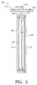
- FIG. 5is a side sectional view depicting an air management system in accordance with another embodiment of the invention.
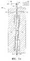
- FIG. 6is a side sectional view depicting a mold that can be used to form the air management system of FIG. 5 .
- FIGS. 7A and 7Bdepict steps of forming the air management system of FIG. 5 using the mold depicted in FIG. 6 .
- certain prior art ink cartridges for use in imaging apparatusinclude a bladder (either an expansible bladder or a collapsible bladder) which facilitates in governing the flow of ink to a print head used to apply the liquid ink to a sheet of imaging media.
- the prior art bladderscan be used either to contain the liquid ink itself, or to contain air which displaces the liquid ink as the ink is consumed from the cartridge.
- these prior art bladderstypically include a separate metal spring, generally in the shape of a shaped plate, which facilitates in biasing wall members of the bladder either towards or away from one another.
- the prior art air management systemstend to be complex in the number of components used in the system, and the number of fabrication steps required to assemble the system.
- the present inventionprovides for an air management system for use in a liquid ink cartridge which includes a reduced number of components.
- Embodiments of the present inventionare particularly useful in applications where the air management system is used to fill the void created by depleted ink as the ink is removed from an ink cartridge during normal use.
- FIG. 1is a side sectional view of a prior art ink cartridge 10 which includes a housing 11 that has a top portion 13 and a bottom portion 12 .
- the top portion 13is typically joined to the bottom portion 12 during assembly by gluing or fusing the portions together.
- the housing bottom portion 12defines an ink reservoir 14 , and supports a print head 15 .
- a standpipe 16admits ink from the ink reservoir 14 into the print head.
- the standpipe 16can be fabricated in-part from a fine mesh which resists the flow of air from the print head 15 into the ink reservoir 14 .
- the ink cartridge 10further includes an expansible bladder-type negative pressure system 20 which is supported by a fitment 22 , which is in turn supported by the housing upper portion 13 .
- the expansible bladder 20 and the fitment 22together make up an air management system 21 .
- the negative pressure system 20is placed within the ink reservoir 14 in the housing lower portion 12 as the upper portion 13 and housing lower portion 12 are joined together.
- the negative pressure system 20 depicted inn FIG. 1includes two expansible bladders 28 A and 28 B.
- Each expansible bladder 28 A, 28 Bis made from a flexible, impermeable film, such as a polyethylene film, so that the bladders can contain air. More specifically, in fabricating the bladders 28 A and 28 B a first polyethylene film 30 is laid on top of a second polyethylene film 32 , and the films are then sealed to one another along their open peripheral edges. The attached films 30 , 32 are then generally folded in half, producing first expansible bladder 28 A having sidewalls 30 A and 30 B, and second expansible bladder 28 B having sidewalls 30 B and 32 B. The folded bladder assembly 20 is secured to the fitment 22 .
- An airway opening 24 in the fitment 22allows ambient air to move into the expansible bladders 28 A, 28 B.
- a metal spring 26is also secured to the outer film layer 30 . This can be accomplished by using heat and/or adhesives. Consequently, when the film/spring assembly is “folded” into the shape depicted in FIG. 1 , the spring 26 produces a first spring member 26 A associated with bladder 28 A, and a second spring member 26 B associated with bladder 28 B. The spring 26 biases the outer film layer 30 in directions “A” and “B” so that the ends 34 A and 34 B of respective bladders 28 A and 28 B are pressed against the inner wall of the housing lower portion 12 .
- the inner film layer 32is free to move inward in directions “H” and “J”.
- the bladders 28 A, 28 Bare initially installed in the housing 11 , the inner film layer 32 is in contact with the outer film layer 30 .
- the pressure within the ink reservoirdrops, causing inner film layers 32 A and 32 B to move in respective directions “H” and “J”.
- an airwaycan be inserted into each bladder (airway 36 A in bladder 28 A, and airway 36 B in bladder 28 B).
- the airways 36 A and 36 Bare in fluid communication with the airway opening 24 , allowing ambient air to flow into the bladders 28 A, 28 B.
- airways 36 A and 36 Bhave respective longitudinal channels 25 A and 25 B (indicated by hidden lines) formed therein.
- the channels 25 A and 25 Ballow air to move in direction “Z” into the lower part 28 L of the bladders 28 A, 28 B.
- the airways 36 A, 36 Bare not provided, it is possible for the lower part 28 L of the bladders 28 A, 28 B to be cut-off from the upper part 28 U of the bladders.
- the airways 36 A, 36 Bprevent this by providing a channel 25 A, 25 B for air to move from the upper part 28 U of the bladders 28 A, 28 B into the lower part 28 L of the bladders.
- the expansible bladders 28 A, 28 Bexpand to fill the void created by the removed ink, so that the pressure of the remaining ink in the reservoir 14 does not become so low that ink will not flow out of the print head 15 . More specifically, the bladder outer walls 30 A and 30 B will be biased in respective directions “A” and “B”, but the bladder inner walls 32 A, 32 B will be free to move in respective directions “H” and “J”, thus allowing bladders 28 A and 28 B to expand or inflate.
- FIG. 2a side sectional view of selected components which make up the expansible bladders 28 A, 28 B of FIG. 1 are depicted. Included are the inner film layer 32 , the air passageways 36 A and 36 B, a release diaphragm 42 , the outer film layer 30 , and the spring member 26 , which has arms 26 A and 26 B.
- the componentsare assembled in a stack, and secured (as by heat or gluing) at the ends 34 A and 34 B of the bladder components and along the edges of the film layers 30 , 32 .
- the assembled stack of componentsis then “folded” in directions “F” to produce the ink pressure control system 20 depicted in FIG. 1 , except that in FIG.
- the arms 26 A, 26 B of the spring 26are compressed from their “at rest” position (i.e., arms 26 A and 26 B are pushed towards one another in directions “H” and “J” in FIG. 1 ).
- an air hole 38is formed in the spring 26
- another air hole 40is formed in the outer film layer 30 .
- a release dot 42which is a silicon-coated or impregnated patch, is placed between the film outer layer 30 and the film inner layer 32 in the area where the outer layer 30 will be heat-attached to the fitment 22 ( FIG. 1 ) to keep the two film layers 30 , 32 from sticking to one another during the heat attachment process.
- the thicknesses of the bladder components depicted in FIGS. 1 and 2are exaggerated in the drawings to facilitate visualization of the components. In reality these components are typically very thin.
- the film layers 30 and 32are typically polyethylene film having a thickness of 1.2 mils, while the metal spring member 26 can be only 5 to 10 mils in thickness.
- the air management system 21( FIG. 1 ) of the prior art includes a significant number of components (fitment 22 , spring 26 , film layers 30 and 32 , airways 36 A and 36 B, and release diaphragm 42 ( FIG. 2 ).
- the large number of componentsconcomitantly requires a significant number of assembly steps, and also requires that all such components be kept on-hand. It is thus desirable to provide an air management system for an ink cartridge that has a fewer number of components.
- FIG. 3a side sectional view depicts a liquid ink cartridge 100 having an air management system 110 in accordance with one embodiment of the invention.
- the ink cartridge 100includes a housing 102 having an outer surface 137 and an inner surface 135 which defines a first fluid reservoir 101 .
- the first fluid reservoir 101is configured to contain liquid ink (not shown).
- the housing 102includes an upper portion 104 and a lower portion 106 , which are configured to be joined together by fusing or gluing, or any other method designed to provide a liquid-tight seal between the upper portion 104 and the lower portion 106 .
- the lower portion 106 of the housing 102further supports a print head 103 and a standpipe 105 , which function in like manner as the print head 15 and standpipe 16 described above with respect to FIG. 1 .
- the ink cartridge 100 of FIG. 3is provided with an air management system 110 which includes a fitment 112 that is supported by the housing upper portion 104 , and a one-piece expansible bladder 120 which is supported by the fitment 112 within the first fluid reservoir 101 .
- the fitment 112includes a flange portion 114 which can be secured to the housing upper portion 104 by studs 109 .
- the studs 109can be extensions of the housing upper portion 104 , and can be heated and deformed to secure the flange portion 114 of the fitment 112 against the inner surface of the upper housing portion 104 .
- the fitment 112further includes an extension portion 115 , a flared portion, 118 , and a recess portion 116 defined between the extension portion 115 and the flared portion 118 .
- the one piece expansible bladder 120can include an elastomeric ring portion 122 defining an opening into the expansible bladder, and the elastomeric ring portion 122 of the expansible bladder can be fitted about the recess portion 116 of the fitment 112 . That is, the one-piece expansible bladder can resemble a balloon. This configuration allows for ease of assembly of the air management system 110 as the ring portion 122 of the bladder 120 merely needs to be slipped over the flared portion 118 of the fitment.
- the one-piece expansible bladder 120 of the air management system 110defines a second fluid reservoir 121 , which is configured to contain air.
- the fitment 112is provided with a vent hole 113 to thereby vent the second fluid reservoir 121 to atmosphere.
- the bladder 120is configured to expand (as indicated by expanded bladder 120 A shown in phantom lines) to thereby increase the second fluid reservoir from a first volume 121 to a second volume 121 A. That is, as ink is removed from the first fluid reservoir 101 during use of the ink cartridge 100 , ambient air moves in direction “C” through the air vent 113 and into the bladder interior 121 , and the bladder 120 expands to fill the void left by the removed ink.
- the expansible bladder 120is fabricated from a material having a shape-memory to thereby bias the expansible bladder towards the first volume 121 (i.e., in a direction opposite to the arrows “D”). In this way, a slight negative pressure is maintained on ink within the first fluid reservoir 101 .
- Materials that can be used to fabricate the expansible bladderinclude natural rubber, neoprene rubber, nitrile rubber, isobutylene-isoprene, chlorosulphonated polyethylene, viton, silicone rubber, acryl-nitrile butadiene, ethylene-propylene, sytrol-butadiene, and flourosilicone.
- the selected materialshould have the shape-memory properties previously described, and should also be chemically resistant to deterioration from exposure to ink in the first fluid reservoir 101 , and from brittleness due to exposure to air contained in the second reservoir 121 defined by the bladder 120 .
- the expansible bladder 120is defined by an inner surface 131 and an outer surface 133 .
- the outer surface 133 of the expansible bladder 120is intended to be exposed to (and in contact with) ink in the first fluid reservoir 101 .
- the removal of ink from the first fluid reservoir 101creates a negative-pressure condition within the ink cartridge 100 , thus causing the bladder 120 to expand in directions “D”.
- the shape-memory characteristics of the material from which the expansible bladder 120 is fabricatedavoids pressure equalization between the ink in the reservoir 101 and the ambient pressure (outside of the ink reservoir), thus maintaining a slight negative pressure within the ink reservoir 101 .
- a slight negative pressure in the ink reservoir 101is desirable to reduce ink “drool” from the print head 103 .
- venting the air chamber 121 of the expansible bladder 120 to the atmosphere via the air vent 113 in the fitment 112as ink in the ink reservoir 101 expands and contracts due to changes in temperature of the ink, a constant pressure will be maintained in the ink reservoir 101 , as established by the shape-memory characteristics of the material from which the expansible bladder 120 is fabricated.
- the expansible bladder 120is configured to expand in directions “D” when the outer surface 133 of the bladder is subjected to a pressure of between about 0.01 psi and 0.50 psi.
- FIG. 4is a plan sectional view of the ink cartridge housing lower portion 106 , wherein the section is taken through the raised portion 130 . As depicted, the raised portion 130 defines scallops which define fluid passageways 132 .
- the housing upper portion and the fitmentcan be produced as a single integral piece, so that the fitment 112 is an integral part of the housing upper portion 104 .
- Thiscan be accomplished using known manufacturing techniques such as injection molding of plastic.
- the expansible bladder 120can still be fitted over a flared portion 118 as depicted in FIG. 3 .
- FIG. 3provides for a two-piece air management system 110 for use in an ink cartridge (the two pieces being the fitment 112 and the expansible bladder 120 ).
- a one-piece air management systemcan be provided.
- FIG. 5is a side sectional view depicting one example of a one-piece air management system 210 in accordance with an embodiment of the invention.
- the air management system 210 depicted in FIG. 5can replace the air management system 110 depicted in FIG. 3 , and therefore another embodiment of the invention includes an ink cartridge which includes a one-piece air management system as will now be more fully described.
- the air management system 210 of FIG. 5can be a single molding.
- the air management system/single molding 210defines a fitment section 212 configured to be supported by a housing of an ink cartridge (such as housing 102 of the ink cartridge 100 of FIG. 3 ).
- the fitment section 212can be provided with one or more mounting holes 215 which can be configured to receive mounting studs, such as mounting studs 109 depicted in FIG. 3 .
- the single molding 210further defines an expansible bladder section 220 , defined by an inner surface 235 and an outer surface 237 , and which extends from the fitment section 212 .
- the expansible bladder section 220is configured to be suspended (by the fitment section 212 ) in a first fluid reservoir (ink reservoir) of an ink cartridge, such as ink reservoir 101 of FIG. 3 .
- the fitment section 212has an air passageway 213 defined therein, which allows ambient air to pass into and out of the expansible bladder section 220 .
- the expansible bladder section 220 of the air management system 210defines a second fluid reservoir 221 , which is configured to contain ambient air (as will be described more fully below).
- the expansible bladder section 220is configured to expand in directions “E” to thereby increase the second fluid reservoir 221 from a first volume to a second volume.
- the expansible bladder section 220expands to fill the resulting void left by the removed ink, and ambient air moves in direction “C” into the air chamber 221 .
- the air management system 210is fabricated from a material having a shape-memory to thereby bias the expansible bladder section towards the first volume (i.e., in a direction opposite of the arrows “E”).
- the expansible section 220 of the air management system 210includes a plurality of surfaces which are joined at acute angles to one another to form bellows 222 .
- the bellows configuration of the expansible bladder section 220allows the bladder section 220 to expand in directions “E” as a result of a vacuum pressure being exerted on the outer surfaces of the bellows 222 (resulting from ink being withdrawn from an ink reservoir in which the bladder 220 is disposed).
- the shape-memory characteristics of the material from which the air management system 210 is fabricatedprovides a slight bias in a direction opposite to arrows “E”, thus producing the desired negative pressure condition in the ink surrounding the expansible bladder 220 .
- a slight negative pressure in the ink reservoiris desirable to reduce ink “drool” from the print head (such as print head 103 of FIG. 3 ).
- the air chamber 221by venting the air chamber 221 to the atmosphere via the air vent 213 in the fitment section, as ink in a surrounding ink reservoir expands and contracts due to changes in temperature of the ink, a constant pressure will be maintained in the ink reservoir, as established by the shape-memory characteristics of the material from which the air management system 210 is fabricated.
- the expansible bladder section 220is configured to expand when the outer surface 237 of the bladder 220 is subjected to a pressure of between about 0.01 psi and 0.50 psi.
- the bellows 222 depicted in FIG. 5are shown having a thicker sidewall than would be used in reality to facilitate visualization of the air management system 210 . Further, the bellows 222 are depicted in FIG. 5 as being somewhat expanded, whereas initially (i.e., before any ink is removed from an ink cartridge in which the bellows can be placed) the bellows would be essentially collapsed to allow for an increase in ink volume in the ink cartridge.
- the housing of the ink cartridgecan be provided with an ink bypass system similar to the ink bypass 130 described above.
- the surfaces which make up the expansible bladder section 220 of the air management system 210 of FIG. 5are depicted as forming bellows 222 , it will be appreciated that other arrangements can be provided to achieve the same result.
- the surfaces which make up the expansible bladder sectioncan be located at acute angles to one another (i.e., generally “folded” with respect to one another) when the expansible bladder is in the collapsed or initial position. This folding of the surfaces allows for reduction of the initial volume of the expansible bladder 220 , thus allowing more room for ink in an associated ink cartridge in which the expansible bladder can be disposed.
- the surfaces which define the expansible bladderbegin to “unfold” (i.e., the angles between the surfaces increase).
- the surfaces which make up the expansible bladder sectioncan be formed in one or more pleats, or they can be folded in a “Z”-fold onto one another, or placed in other initial positions to allow expansion of the bladder, but to reduce the volume of the expansible bladder when it is in the collapsed state.
- Materials from which the air management system 210 of FIG. 5 can be fabricatedinclude high density polyethylene, low density polyethylene, polyvinyl chloride, and polypropylene.
- the material selected for fabrication of the air management systemshould be chemically resistant to ink the expansible bladder section will come into contact with, and should provide the desired shape-memory characteristics described above. Additionally, the selected material for fabrication of the air management system should accommodate a fabrication process that allows a one-piece, single molding, air management system to be fabricated.
- FIG. 6is a side sectional view depicting a mold 300 that can be used to form the air management system 210 of FIG. 5 .
- the mold 300defines a single cavity 310 , which further defines a fitment section 312 and expansible bladder sections 320 .
- the fitment section 312 of the cavity 310is used to form the fitment 212 of the air management system 210
- the expansible bladder sections 320 of the cavity 310are used to form the expansible bladder 220 of the air management system 210 .
- the mold 300further includes an inlet opening 302 in which an injection probe 322 can be inserted.
- the mold 300further includes an outlet opening 330 which can be selectively opened and closed by an outlet valve 332 , the operation of which will be described more fully below.
- the injection probe 322is connected to a three-way valve 324 , which allows a “plastic” 326 , or a “gas” 328 , to be selectively injected into the void 310 of the mold via the probe 322 .
- the “plastic” 326can be any material selected for fabrication of the air management system 210 ( FIG. 5 ), as previously described.
- FIGS. 7A and 7BOne non-limiting example of operating the mold 300 to form an air management system (such as air management system 210 of FIG. 5 ) will now be described with respect to FIGS. 7A and 7B .
- a single-molding (one-piece) air management system(such as air management system 210 of FIG. 5 ) is fabricated using a single mold, and a two-step process.
- the fitment of the air management systemis injection molded
- the expansible bladder of the air management systemis blow molded.
- FIG. 7A“plastic” 326 has been injection molded into the fitment section 312 of the mold 300 via the probe 322 , as indicated by material “P” in fitment section 312 , to form the fitment 212 of the air management system 210 ( FIG. 5 ).
- the three-way valve 324is closed to the “gas” 328 during this injection molding process.
- the bulk of the expansible bladder sections 320 of the mold 300have been filled with a liquid “L” to prevent migration of the “plastic” into the expansible bladder sections 320 during the injection molding process.
- a predetermined volume in the expansible bladder sections 320is not filled with the liquid “L” to thereby allow a surplus mass “M” of the “plastic” to be injected into the upper portions of the expansible bladder sections 320 .
- traditional venting methods used in injection molding processescan be provided with the mold 300 to allow air within the fitment section 312 and the upper portions of the expansible bladder sections 320 to be vented during the injecting molding process.
- the outlet valve 332is opened, allowing the liquid “L” to drain from the expansible bladder sections 320 via the outlet opening 330 .
- the three-way valve 324is closed to the source of “plastic” 326 , and the valve 324 is opened to the source of “gas” 328 .
- the “gas” 328is then blown into the mold 300 via the probe 322 .
- the surplus mass “M” of “plastic”is blown into the expansible bladder sections 320 of the mold 300 to form the expansible bladder 220 of the air management system 210 ( FIG. 5 ).
- the gas “G” ( 328 )is continued to be blown into the mold 300 until the expansible bladder section 220 is completely formed. Thereafter the probe 322 is removed, thereby forming the air vent 213 ( FIG. 5 ) in the fitment 212 .
- the mold 300can be a split mold (split along the section depicted in FIG. 6 ), so that the mold can be separated and the resulting fully formed air management system removed.
- heat “Q”can be added to the expansible bladder sections 320 to maintain the surplus mass “M” of the “plastic” in a moldable state.
- Heatcan be added, for example, by placing an electrical heating coil around the expansible bladder sections 320 of the mold 300 . Further, heat can be added by heating the liquid “L”.
- heatcan be removed from the fitment section 312 of the mold 300 . Heat can be removed from the fitment section 312 by placing a refrigeration coil around the fitment section 312 of the mold 300 , for example.
- FIGS. 7A and 7B of producing a single molded air management system for use in an ink cartridgeis exemplary only, and that other manufacturing processes can be used.
- the fitment section 212 and the expansible bladder section 220 of the air management system 210 depicted in FIG. 5can be produced separately (such as by separate respective injection molding and blow molding processes), and then the two components can be joined together by gluing, fusing, ultrasonic welding, heating, etc. That is, the single molded air management system does not have to be produced in a single mold, but when the air management system is completed, it results in a single part which is produced (at least in-part) by a molding process.
- the fitment section and/or the expansible bladder sectioncan be formed by processes other than molding processes, and the two sections can thereafter be joined together (such as by gluing, fusing, ultrasonic welding, heating, etc.) to thereby form an air management system for use in an ink cartridge, such that the air management system has a fitment section configured to be supported by the ink cartridge, and an expansible bladder section which integrally extends from the fitment section.
- the air management systemhas a fitment section configured to be supported by the ink cartridge, and an expansible bladder section which integrally extends from the fitment section.
Landscapes
- Ink Jet (AREA)
Abstract
Description
Claims (12)
Priority Applications (3)
| Application Number | Priority Date | Filing Date | Title |
|---|---|---|---|
| US10/352,688US6966639B2 (en) | 2003-01-28 | 2003-01-28 | Ink cartridge and air management system for an ink cartridge |
| JP2004019225AJP2004230890A (en) | 2003-01-28 | 2004-01-28 | Ink cartridge |
| US11/142,173US20050219337A1 (en) | 2003-01-28 | 2005-05-31 | Ink cartridge and air management system for an ink cartridge |
Applications Claiming Priority (1)
| Application Number | Priority Date | Filing Date | Title |
|---|---|---|---|
| US10/352,688US6966639B2 (en) | 2003-01-28 | 2003-01-28 | Ink cartridge and air management system for an ink cartridge |
Related Child Applications (1)
| Application Number | Title | Priority Date | Filing Date |
|---|---|---|---|
| US11/142,173DivisionUS20050219337A1 (en) | 2003-01-28 | 2005-05-31 | Ink cartridge and air management system for an ink cartridge |
Publications (2)
| Publication Number | Publication Date |
|---|---|
| US20040145638A1 US20040145638A1 (en) | 2004-07-29 |
| US6966639B2true US6966639B2 (en) | 2005-11-22 |
Family
ID=32736039
Family Applications (2)
| Application Number | Title | Priority Date | Filing Date |
|---|---|---|---|
| US10/352,688Expired - LifetimeUS6966639B2 (en) | 2003-01-28 | 2003-01-28 | Ink cartridge and air management system for an ink cartridge |
| US11/142,173AbandonedUS20050219337A1 (en) | 2003-01-28 | 2005-05-31 | Ink cartridge and air management system for an ink cartridge |
Family Applications After (1)
| Application Number | Title | Priority Date | Filing Date |
|---|---|---|---|
| US11/142,173AbandonedUS20050219337A1 (en) | 2003-01-28 | 2005-05-31 | Ink cartridge and air management system for an ink cartridge |
Country Status (2)
| Country | Link |
|---|---|
| US (2) | US6966639B2 (en) |
| JP (1) | JP2004230890A (en) |
Cited By (20)
| Publication number | Priority date | Publication date | Assignee | Title |
|---|---|---|---|---|
| US20060131226A1 (en)* | 2004-12-17 | 2006-06-22 | Industrial Technology Research Institute | Filter column module |
| US20060227188A1 (en)* | 2005-03-30 | 2006-10-12 | Pui-Kuong Lui | Ink cartridge |
| US20070126821A1 (en)* | 2005-12-05 | 2007-06-07 | Silverbrook Research Pty Ltd | Ink cartridge with sealed air inlet |
| US20070126807A1 (en)* | 2005-12-05 | 2007-06-07 | Silverbrook Research Pty Ltd | Ink reservoir with constant hydrostatic pressure outlet |
| US20070126815A1 (en)* | 2005-12-05 | 2007-06-07 | Silverbrook Research Pty Ltd | Ink reservoir with pressure regulating valve |
| US20070126806A1 (en)* | 2005-12-05 | 2007-06-07 | Silverbrook Research Pty Ltd | Ink reservoir with air bag |
| US20080071243A1 (en)* | 2006-09-20 | 2008-03-20 | Yandell Marion E | Vial Assembly and Method for Reducing Nosocomial Infections |
| US20090015641A1 (en)* | 2005-12-05 | 2009-01-15 | Silverbrook Research Pty Ltd | Printer arrangement incorporating a printhead maintenance station |
| US20090058967A1 (en)* | 2005-12-05 | 2009-03-05 | Silverbrook Research Pty Ltd | Inkjet printer with resilient connection between printhead cartridge and ink cartridge |
| US20090066764A1 (en)* | 2005-12-05 | 2009-03-12 | Silverbrook Research Pty Ltd | Printer with mutually engaging ink cartridge, printhead cartridge and printer body |
| US20090091602A1 (en)* | 2005-12-05 | 2009-04-09 | Silverbrook Research Pty Ltd | Inkjet Printer With Printhead Cartridge And Cradle That Interengage Via An Overcentre Mechanism |
| US20090120512A1 (en)* | 2005-12-05 | 2009-05-14 | Silverbrook Research Pty Ltd | Valve assembly for a printer ink cartridge having a spring-biased pressure regulator |
| US20090237476A1 (en)* | 2005-12-05 | 2009-09-24 | Silverbrook Research Pty Ltd | Ink cartridge with high flowrate, self sealing outlet |
| US20100171800A1 (en)* | 2004-01-21 | 2010-07-08 | Silverbrook Research Pty Ltd | Ink storage module with displaceable upper and lower plates and displaceable upper and lower collars |
| US20100182387A1 (en)* | 2004-01-21 | 2010-07-22 | Silverbrook Research Pty Ltd | Reservoir assembly for supplying fluid to printhead |
| US20100214382A1 (en)* | 2005-12-05 | 2010-08-26 | Silverbrook Research Pty Ltd | Printhead cartridge valve assembly with diaphragm pressure regulator |
| US7789871B1 (en) | 2006-09-20 | 2010-09-07 | Yandell Marion E | Vial assembly and method for reducing nosocomial infections |
| US20100298806A1 (en)* | 2006-09-20 | 2010-11-25 | Yandell Marion E | Vial assembly and method for reducing nosocomial infections |
| US8357137B2 (en) | 2011-06-24 | 2013-01-22 | Yandell Marion E | Bung assembly for anti vacuum lock medical vials |
| US10065425B2 (en) | 2015-03-06 | 2018-09-04 | Hewlett-Packard Development Company, L.P. | Printing fluid container |
Families Citing this family (11)
| Publication number | Priority date | Publication date | Assignee | Title |
|---|---|---|---|---|
| US7121655B2 (en)* | 2004-01-21 | 2006-10-17 | Silverbrook Research Pty Ltd | Inkjet printer cartridge refill dispenser |
| US7303255B2 (en)* | 2004-01-21 | 2007-12-04 | Silverbrook Research Pty Ltd | Inkjet printer cartridge with a compressed air port |
| US7097291B2 (en) | 2004-01-21 | 2006-08-29 | Silverbrook Research Pty Ltd | Inkjet printer cartridge with ink refill port having multiple ink couplings |
| US20050157112A1 (en) | 2004-01-21 | 2005-07-21 | Silverbrook Research Pty Ltd | Inkjet printer cradle with shaped recess for receiving a printer cartridge |
| US12370305B2 (en) | 2006-02-09 | 2025-07-29 | Deka Products Limited Partnership | Patch-sized fluid delivery systems and methods |
| EP3165247B1 (en) | 2006-02-09 | 2020-10-28 | DEKA Products Limited Partnership | Pumping fluid delivery systems and methods using force application assembley |
| JP4819581B2 (en)* | 2006-06-02 | 2011-11-24 | 富士フイルム株式会社 | Liquid storage device and image forming apparatus |
| CA2596123A1 (en) | 2007-08-03 | 2009-02-03 | Carlo Fascio | Refillable ink cartridge |
| US8393696B2 (en)* | 2009-12-07 | 2013-03-12 | Xerox Corporation | Method and device for controlling the mass of an ink droplet |
| CN110300664B (en)* | 2017-02-10 | 2020-12-11 | 惠普发展公司,有限责任合伙企业 | Fluid Box |
| EP3651993A1 (en)* | 2017-07-12 | 2020-05-20 | Hewlett-Packard Development Company, L.P. | Determining an out-of-liquid condition |
Citations (10)
| Publication number | Priority date | Publication date | Assignee | Title |
|---|---|---|---|---|
| US4234017A (en)* | 1979-11-05 | 1980-11-18 | Normand Trust | Accumulator device or the like |
| US5040001A (en) | 1990-06-27 | 1991-08-13 | Hewlett-Packard Company | Collapsible storage bladder for ink cartridges |
| US5409134A (en)* | 1990-01-12 | 1995-04-25 | Hewlett-Packard Corporation | Pressure-sensitive accumulator for ink-jet pens |
| US5515092A (en) | 1992-03-18 | 1996-05-07 | Hewlett-Packard Company | Two material frame having dissimilar properties for thermal ink-jet cartridge |
| US5988803A (en) | 1997-12-12 | 1999-11-23 | Lexmark International, Inc. | Ink leakage control arrangement for an ink cartridge |
| US6174053B1 (en)* | 1993-05-13 | 2001-01-16 | Canon Kabushiki Kaisha | Ink tank, head cartridge and ink jet printing apparatus |
| US6196669B1 (en) | 1994-10-31 | 2001-03-06 | Hewlett-Packard Company | High durability pressure control bladder for use in an ink delivery system |
| US6206515B1 (en) | 1992-12-22 | 2001-03-27 | Hewlett-Packard Company | Double compartment ink-jet cartridge with optimum snout |
| US6247806B1 (en) | 1996-07-01 | 2001-06-19 | Canon Kabushiki Kaisha | Liquid ejection head cartridge and liquid container usable therewith |
| US6293666B1 (en)* | 1999-08-11 | 2001-09-25 | Microjet Technology Co., Ltd. | Ink-jet cartridge with pressure adjustment device |
Family Cites Families (16)
| Publication number | Priority date | Publication date | Assignee | Title |
|---|---|---|---|---|
| US2345977A (en)* | 1942-06-24 | 1944-04-04 | Libbey Owens Ford Glass Co | Method of molding hollow bodies |
| US3672544A (en)* | 1970-06-22 | 1972-06-27 | Ciba Geigy Corp | Multi-component product dispenser |
| JP2840482B2 (en)* | 1991-06-19 | 1998-12-24 | キヤノン株式会社 | Ink tank, inkjet head cartridge, and inkjet recording apparatus |
| EP0616591A1 (en)* | 1991-12-18 | 1994-09-28 | The Procter & Gamble Company | Package with replaceable inner receptacle having large integrally molded fitment |
| US5650811A (en)* | 1993-05-21 | 1997-07-22 | Hewlett-Packard Company | Apparatus for providing ink to a printhead |
| US5975686A (en)* | 1994-10-31 | 1999-11-02 | Hewlett-Packard Company | Regulator for a free-ink inkjet pen |
| US6017118A (en)* | 1995-04-27 | 2000-01-25 | Hewlett-Packard Company | High performance ink container with efficient construction |
| US5688570A (en)* | 1995-10-13 | 1997-11-18 | Crown Cork & Seal Company, Inc. | Method and apparatus for forming a multi-layer preform |
| EP0827836B1 (en)* | 1996-02-21 | 2005-05-04 | Seiko Epson Corporation | Ink cartridge |
| US20030107626A1 (en)* | 2000-08-16 | 2003-06-12 | Xiao Qingguo | Ink cartridge having bellows valve, ink filling method and apparatus used thereof |
| US6514451B1 (en)* | 2000-06-30 | 2003-02-04 | Schmalbach-Lubeca Ag | Method for producing plastic containers having high crystallinity bases |
| US6660214B2 (en)* | 2001-02-23 | 2003-12-09 | Essef Corporation | Pressure vessel manufacture method |
| TW541248B (en)* | 2001-03-16 | 2003-07-11 | Benq Corp | Ink cartridge |
| FR2833577B1 (en)* | 2001-12-14 | 2004-03-12 | Lablabo | RIGID CONTAINER DEVICE AND FLEXIBLE MULTIPLE POCKETS FOR PACKAGING AND DELIVERY OF FLUIDS |
| US6702436B2 (en)* | 2002-01-30 | 2004-03-09 | Hewlett-Packard Development Company, L.P. | Fluid ejection cartridge including a compliant filter |
| US6981764B2 (en)* | 2003-12-10 | 2006-01-03 | Hewlett-Packard Development Company, L.P. | Heat stake assembly and method for forming a stake pattern |
- 2003
- 2003-01-28USUS10/352,688patent/US6966639B2/ennot_activeExpired - Lifetime
- 2004
- 2004-01-28JPJP2004019225Apatent/JP2004230890A/enactivePending
- 2005
- 2005-05-31USUS11/142,173patent/US20050219337A1/ennot_activeAbandoned
Patent Citations (10)
| Publication number | Priority date | Publication date | Assignee | Title |
|---|---|---|---|---|
| US4234017A (en)* | 1979-11-05 | 1980-11-18 | Normand Trust | Accumulator device or the like |
| US5409134A (en)* | 1990-01-12 | 1995-04-25 | Hewlett-Packard Corporation | Pressure-sensitive accumulator for ink-jet pens |
| US5040001A (en) | 1990-06-27 | 1991-08-13 | Hewlett-Packard Company | Collapsible storage bladder for ink cartridges |
| US5515092A (en) | 1992-03-18 | 1996-05-07 | Hewlett-Packard Company | Two material frame having dissimilar properties for thermal ink-jet cartridge |
| US6206515B1 (en) | 1992-12-22 | 2001-03-27 | Hewlett-Packard Company | Double compartment ink-jet cartridge with optimum snout |
| US6174053B1 (en)* | 1993-05-13 | 2001-01-16 | Canon Kabushiki Kaisha | Ink tank, head cartridge and ink jet printing apparatus |
| US6196669B1 (en) | 1994-10-31 | 2001-03-06 | Hewlett-Packard Company | High durability pressure control bladder for use in an ink delivery system |
| US6247806B1 (en) | 1996-07-01 | 2001-06-19 | Canon Kabushiki Kaisha | Liquid ejection head cartridge and liquid container usable therewith |
| US5988803A (en) | 1997-12-12 | 1999-11-23 | Lexmark International, Inc. | Ink leakage control arrangement for an ink cartridge |
| US6293666B1 (en)* | 1999-08-11 | 2001-09-25 | Microjet Technology Co., Ltd. | Ink-jet cartridge with pressure adjustment device |
Cited By (46)
| Publication number | Priority date | Publication date | Assignee | Title |
|---|---|---|---|---|
| US20100171800A1 (en)* | 2004-01-21 | 2010-07-08 | Silverbrook Research Pty Ltd | Ink storage module with displaceable upper and lower plates and displaceable upper and lower collars |
| US8398216B2 (en)* | 2004-01-21 | 2013-03-19 | Zamtec Ltd | Reservoir assembly for supplying fluid to printhead |
| US8382266B2 (en) | 2004-01-21 | 2013-02-26 | Zamtec Ltd | Ink storage module with displaceable upper and lower plates and displaceable upper and lower collars |
| US20100182387A1 (en)* | 2004-01-21 | 2010-07-22 | Silverbrook Research Pty Ltd | Reservoir assembly for supplying fluid to printhead |
| US20060131226A1 (en)* | 2004-12-17 | 2006-06-22 | Industrial Technology Research Institute | Filter column module |
| US20060227188A1 (en)* | 2005-03-30 | 2006-10-12 | Pui-Kuong Lui | Ink cartridge |
| US7255432B2 (en)* | 2005-03-30 | 2007-08-14 | Monitek Electronics Limited | Ink cartridge |
| US8007092B2 (en)* | 2005-12-05 | 2011-08-30 | Silverbrook Research Pty Ltd | Air tight ink cartridge with unobstructed ink outlet |
| US20100214382A1 (en)* | 2005-12-05 | 2010-08-26 | Silverbrook Research Pty Ltd | Printhead cartridge valve assembly with diaphragm pressure regulator |
| US7431443B2 (en)* | 2005-12-05 | 2008-10-07 | Silverbrook Research Pty Ltd | Ink reservoir with pressure regulating valve |
| US20080252704A1 (en)* | 2005-12-05 | 2008-10-16 | Silverbrook Research Pty Ltd | Printer with cartridge dock for rupturing seal on cartridge |
| US20080297558A1 (en)* | 2005-12-05 | 2008-12-04 | Silverbrook Research Pty Ltd | Printhead maintenance assembly for an inkjet printer |
| US20090015641A1 (en)* | 2005-12-05 | 2009-01-15 | Silverbrook Research Pty Ltd | Printer arrangement incorporating a printhead maintenance station |
| US20090058967A1 (en)* | 2005-12-05 | 2009-03-05 | Silverbrook Research Pty Ltd | Inkjet printer with resilient connection between printhead cartridge and ink cartridge |
| US20090066764A1 (en)* | 2005-12-05 | 2009-03-12 | Silverbrook Research Pty Ltd | Printer with mutually engaging ink cartridge, printhead cartridge and printer body |
| US20090091602A1 (en)* | 2005-12-05 | 2009-04-09 | Silverbrook Research Pty Ltd | Inkjet Printer With Printhead Cartridge And Cradle That Interengage Via An Overcentre Mechanism |
| US7524023B2 (en)* | 2005-12-05 | 2009-04-28 | Silverbrook Research Pty Ltd | Ink reservoir with constant hydrostatic pressure outlet |
| US7527353B2 (en)* | 2005-12-05 | 2009-05-05 | Silverbrook Research Pty Ltd | Ink cartridge with sealed air inlet |
| US20090120512A1 (en)* | 2005-12-05 | 2009-05-14 | Silverbrook Research Pty Ltd | Valve assembly for a printer ink cartridge having a spring-biased pressure regulator |
| US20090160916A1 (en)* | 2005-12-05 | 2009-06-25 | Silverbrook Research Pty Ltd | Air tight ink cartridge with unobstructed ink outlet |
| US20090201350A1 (en)* | 2005-12-05 | 2009-08-13 | Silverbrook Research Pty Ltd | Ink Cartridge For Constant Ink Pressure |
| US20090237476A1 (en)* | 2005-12-05 | 2009-09-24 | Silverbrook Research Pty Ltd | Ink cartridge with high flowrate, self sealing outlet |
| US20070126821A1 (en)* | 2005-12-05 | 2007-06-07 | Silverbrook Research Pty Ltd | Ink cartridge with sealed air inlet |
| US8382268B2 (en) | 2005-12-05 | 2013-02-26 | Zamtec Ltd | Ink cartridge with high flow rate supply to printhead |
| US20070126806A1 (en)* | 2005-12-05 | 2007-06-07 | Silverbrook Research Pty Ltd | Ink reservoir with air bag |
| US7771008B2 (en) | 2005-12-05 | 2010-08-10 | Silverbrook Research Pty Ltd | Printhead maintenance assembly for an inkjet printer |
| US7431440B2 (en)* | 2005-12-05 | 2008-10-07 | Silverbrook Research Pty Ltd | Ink reservoir with air bag |
| US20070126807A1 (en)* | 2005-12-05 | 2007-06-07 | Silverbrook Research Pty Ltd | Ink reservoir with constant hydrostatic pressure outlet |
| US20100253737A1 (en)* | 2005-12-05 | 2010-10-07 | Silverbrook Research Pty Ltd | Printhead maintenance assembly for inkjet printer |
| US8360548B2 (en) | 2005-12-05 | 2013-01-29 | Zamtec Ltd | Printhead maintenance assembly for inkjet printer |
| US7845781B2 (en) | 2005-12-05 | 2010-12-07 | Silverbrook Research Pty Ltd | Printer with cartridge dock for rupturing seal on cartridge |
| US8118416B2 (en) | 2005-12-05 | 2012-02-21 | Silverbrook Reasearch Pty Ltd | Valve assembly for a printer ink cartridge having a spring-biased pressure regulator |
| US7971965B2 (en) | 2005-12-05 | 2011-07-05 | Silverbrook Research Pty Ltd | Ink cartridge for constant ink pressure |
| US20070126815A1 (en)* | 2005-12-05 | 2007-06-07 | Silverbrook Research Pty Ltd | Ink reservoir with pressure regulating valve |
| US8011766B2 (en) | 2005-12-05 | 2011-09-06 | Silverbrook Research Pty Ltd | Printhead cartridge valve assembly with diaphragm pressure regulator |
| US8075116B2 (en) | 2005-12-05 | 2011-12-13 | Silverbrook Research Pty Ltd | Ink cartridge with high flowrate, self sealing outlet |
| US8087763B2 (en) | 2005-12-05 | 2012-01-03 | Silverbrook Research Pty Ltd | Inkjet printer with printhead cartridge and cradle that interengage via an overcentre mechanism |
| US8100518B2 (en) | 2005-12-05 | 2012-01-24 | Silverbrook Research Pty Ltd | Inkjet printer with resilient connection between printhead cartridge and ink cartridge |
| US8109621B2 (en) | 2005-12-05 | 2012-02-07 | Silverbrook Research Pty Ltd | Printer with mutually engaging ink cartridge, printhead cartridge and printer body |
| US7887528B2 (en) | 2006-09-20 | 2011-02-15 | Yandell Marion E | Vial assembly and method for reducing nosocomial infections |
| US20100298806A1 (en)* | 2006-09-20 | 2010-11-25 | Yandell Marion E | Vial assembly and method for reducing nosocomial infections |
| US7789871B1 (en) | 2006-09-20 | 2010-09-07 | Yandell Marion E | Vial assembly and method for reducing nosocomial infections |
| US20080071243A1 (en)* | 2006-09-20 | 2008-03-20 | Yandell Marion E | Vial Assembly and Method for Reducing Nosocomial Infections |
| US7618408B2 (en) | 2006-09-20 | 2009-11-17 | Yandell Marion E | Vial assembly and method for reducing nosocomial infections |
| US8357137B2 (en) | 2011-06-24 | 2013-01-22 | Yandell Marion E | Bung assembly for anti vacuum lock medical vials |
| US10065425B2 (en) | 2015-03-06 | 2018-09-04 | Hewlett-Packard Development Company, L.P. | Printing fluid container |
Also Published As
| Publication number | Publication date |
|---|---|
| JP2004230890A (en) | 2004-08-19 |
| US20040145638A1 (en) | 2004-07-29 |
| US20050219337A1 (en) | 2005-10-06 |
Similar Documents
| Publication | Publication Date | Title |
|---|---|---|
| US6966639B2 (en) | Ink cartridge and air management system for an ink cartridge | |
| JP4246787B1 (en) | Ink storage container | |
| CA2178883C (en) | Ink container, manufacturing method therefor, ink jet cartridge and ink jet apparatus | |
| US9056479B2 (en) | Pressure bag | |
| TWI244985B (en) | Ink tank | |
| US20080303879A1 (en) | Ink cartridge for inkjet printers | |
| JP3831806B2 (en) | Inkjet pen bellows system | |
| JP2005170515A (en) | Holding structure of fluid for producing back pressure | |
| US6883907B2 (en) | Ink cartridge and expansible bladder for an ink cartridge | |
| US6817707B1 (en) | Pressure controlled ink jet printhead assembly | |
| US20050012794A1 (en) | Refillable ink cartridge for an inkjet printer | |
| WO2009014224A1 (en) | Ink container, ink supplying system, and ink jet recording apparatus | |
| US7021751B2 (en) | Robust gasket seal for an inkjet printhead | |
| CN204605195U (en) | A kind of print cartridge | |
| CN205395458U (en) | Ink box | |
| TWI607888B (en) | Regulator component,printer sub-assembly and printer system comprising printer sub-assembly | |
| US6742880B2 (en) | Dual chamber cartridge | |
| CN109249706A (en) | Fluid stores component | |
| JP4210225B2 (en) | Installing the inkjet pen and vent plug | |
| JP2008143171A (en) | Ink storage container | |
| JP2004322658A (en) | Ink supply control device | |
| JP2004122498A (en) | Method of manufacturing convex sheet used for liquid storage container, liquid storage container having the same, and method of manufacturing the same | |
| JP2009233926A (en) | Ink storage container | |
| KR20050062968A (en) | Ink-jet cartridge and its producing method | |
| JP2009018443A (en) | Inkjet recording device |
Legal Events
| Date | Code | Title | Description |
|---|---|---|---|
| AS | Assignment | Owner name:HEWLETT-PACKARD COMPANY, COLORADO Free format text:ASSIGNMENT OF ASSIGNORS INTEREST;ASSIGNOR:MARTINEZ-PACHECO, ADRIAN;REEL/FRAME:013776/0370 Effective date:20030121 | |
| AS | Assignment | Owner name:HEWLETT-PACKARD DEVELOPMENT COMPANY, L.P., COLORADO Free format text:ASSIGNMENT OF ASSIGNORS INTEREST;ASSIGNOR:HEWLETT-PACKARD COMPANY;REEL/FRAME:013776/0928 Effective date:20030131 Owner name:HEWLETT-PACKARD DEVELOPMENT COMPANY, L.P., COLORAD Free format text:ASSIGNMENT OF ASSIGNORS INTEREST;ASSIGNOR:HEWLETT-PACKARD COMPANY;REEL/FRAME:013776/0928 Effective date:20030131 Owner name:HEWLETT-PACKARD DEVELOPMENT COMPANY, L.P.,COLORADO Free format text:ASSIGNMENT OF ASSIGNORS INTEREST;ASSIGNOR:HEWLETT-PACKARD COMPANY;REEL/FRAME:013776/0928 Effective date:20030131 | |
| STCF | Information on status: patent grant | Free format text:PATENTED CASE | |
| FPAY | Fee payment | Year of fee payment:4 | |
| FPAY | Fee payment | Year of fee payment:8 | |
| FPAY | Fee payment | Year of fee payment:12 |