US6966081B1 - Transport and positioning system for use in hospital operating rooms - Google Patents
Transport and positioning system for use in hospital operating roomsDownload PDFInfo
- Publication number
- US6966081B1 US6966081B1US10/866,852US86685204AUS6966081B1US 6966081 B1US6966081 B1US 6966081B1US 86685204 AUS86685204 AUS 86685204AUS 6966081 B1US6966081 B1US 6966081B1
- Authority
- US
- United States
- Prior art keywords
- patient
- inflatable
- inflatable member
- chambers
- operating room
- Prior art date
- Legal status (The legal status is an assumption and is not a legal conclusion. Google has not performed a legal analysis and makes no representation as to the accuracy of the status listed.)
- Expired - Lifetime, expires
Links
Images


Classifications
- A—HUMAN NECESSITIES
- A61—MEDICAL OR VETERINARY SCIENCE; HYGIENE
- A61G—TRANSPORT, PERSONAL CONVEYANCES, OR ACCOMMODATION SPECIALLY ADAPTED FOR PATIENTS OR DISABLED PERSONS; OPERATING TABLES OR CHAIRS; CHAIRS FOR DENTISTRY; FUNERAL DEVICES
- A61G7/00—Beds specially adapted for nursing; Devices for lifting patients or disabled persons
- A61G7/10—Devices for lifting patients or disabled persons, e.g. special adaptations of hoists thereto
- A61G7/104—Devices carried or supported by
- A61G7/1046—Mobile bases, e.g. having wheels
- A—HUMAN NECESSITIES
- A61—MEDICAL OR VETERINARY SCIENCE; HYGIENE
- A61G—TRANSPORT, PERSONAL CONVEYANCES, OR ACCOMMODATION SPECIALLY ADAPTED FOR PATIENTS OR DISABLED PERSONS; OPERATING TABLES OR CHAIRS; CHAIRS FOR DENTISTRY; FUNERAL DEVICES
- A61G13/00—Operating tables; Auxiliary appliances therefor
- A61G13/0036—Orthopaedic operating tables
- A61G13/0054—Orthopaedic operating tables specially adapted for back or spinal surgeries
- A—HUMAN NECESSITIES
- A61—MEDICAL OR VETERINARY SCIENCE; HYGIENE
- A61G—TRANSPORT, PERSONAL CONVEYANCES, OR ACCOMMODATION SPECIALLY ADAPTED FOR PATIENTS OR DISABLED PERSONS; OPERATING TABLES OR CHAIRS; CHAIRS FOR DENTISTRY; FUNERAL DEVICES
- A61G13/00—Operating tables; Auxiliary appliances therefor
- A61G13/10—Parts, details or accessories
- A61G13/12—Rests specially adapted therefor; Arrangements of patient-supporting surfaces
- A61G13/1205—Rests specially adapted therefor; Arrangements of patient-supporting surfaces for specific parts of the body
- A61G13/121—Head or neck
- A—HUMAN NECESSITIES
- A61—MEDICAL OR VETERINARY SCIENCE; HYGIENE
- A61G—TRANSPORT, PERSONAL CONVEYANCES, OR ACCOMMODATION SPECIALLY ADAPTED FOR PATIENTS OR DISABLED PERSONS; OPERATING TABLES OR CHAIRS; CHAIRS FOR DENTISTRY; FUNERAL DEVICES
- A61G13/00—Operating tables; Auxiliary appliances therefor
- A61G13/10—Parts, details or accessories
- A61G13/12—Rests specially adapted therefor; Arrangements of patient-supporting surfaces
- A61G13/1205—Rests specially adapted therefor; Arrangements of patient-supporting surfaces for specific parts of the body
- A61G13/122—Upper body, e.g. chest
- A—HUMAN NECESSITIES
- A61—MEDICAL OR VETERINARY SCIENCE; HYGIENE
- A61G—TRANSPORT, PERSONAL CONVEYANCES, OR ACCOMMODATION SPECIALLY ADAPTED FOR PATIENTS OR DISABLED PERSONS; OPERATING TABLES OR CHAIRS; CHAIRS FOR DENTISTRY; FUNERAL DEVICES
- A61G13/00—Operating tables; Auxiliary appliances therefor
- A61G13/10—Parts, details or accessories
- A61G13/12—Rests specially adapted therefor; Arrangements of patient-supporting surfaces
- A61G13/1205—Rests specially adapted therefor; Arrangements of patient-supporting surfaces for specific parts of the body
- A61G13/123—Lower body, e.g. pelvis, hip, buttocks
- A—HUMAN NECESSITIES
- A61—MEDICAL OR VETERINARY SCIENCE; HYGIENE
- A61G—TRANSPORT, PERSONAL CONVEYANCES, OR ACCOMMODATION SPECIALLY ADAPTED FOR PATIENTS OR DISABLED PERSONS; OPERATING TABLES OR CHAIRS; CHAIRS FOR DENTISTRY; FUNERAL DEVICES
- A61G13/00—Operating tables; Auxiliary appliances therefor
- A61G13/10—Parts, details or accessories
- A61G13/12—Rests specially adapted therefor; Arrangements of patient-supporting surfaces
- A61G13/1205—Rests specially adapted therefor; Arrangements of patient-supporting surfaces for specific parts of the body
- A61G13/1245—Knees, upper or lower legs
- A—HUMAN NECESSITIES
- A61—MEDICAL OR VETERINARY SCIENCE; HYGIENE
- A61G—TRANSPORT, PERSONAL CONVEYANCES, OR ACCOMMODATION SPECIALLY ADAPTED FOR PATIENTS OR DISABLED PERSONS; OPERATING TABLES OR CHAIRS; CHAIRS FOR DENTISTRY; FUNERAL DEVICES
- A61G13/00—Operating tables; Auxiliary appliances therefor
- A61G13/10—Parts, details or accessories
- A61G13/12—Rests specially adapted therefor; Arrangements of patient-supporting surfaces
- A61G13/1205—Rests specially adapted therefor; Arrangements of patient-supporting surfaces for specific parts of the body
- A61G13/125—Ankles or feet
- A—HUMAN NECESSITIES
- A61—MEDICAL OR VETERINARY SCIENCE; HYGIENE
- A61G—TRANSPORT, PERSONAL CONVEYANCES, OR ACCOMMODATION SPECIALLY ADAPTED FOR PATIENTS OR DISABLED PERSONS; OPERATING TABLES OR CHAIRS; CHAIRS FOR DENTISTRY; FUNERAL DEVICES
- A61G13/00—Operating tables; Auxiliary appliances therefor
- A61G13/10—Parts, details or accessories
- A61G13/12—Rests specially adapted therefor; Arrangements of patient-supporting surfaces
- A61G13/1205—Rests specially adapted therefor; Arrangements of patient-supporting surfaces for specific parts of the body
- A61G13/1255—Shoulders
- A—HUMAN NECESSITIES
- A61—MEDICAL OR VETERINARY SCIENCE; HYGIENE
- A61G—TRANSPORT, PERSONAL CONVEYANCES, OR ACCOMMODATION SPECIALLY ADAPTED FOR PATIENTS OR DISABLED PERSONS; OPERATING TABLES OR CHAIRS; CHAIRS FOR DENTISTRY; FUNERAL DEVICES
- A61G13/00—Operating tables; Auxiliary appliances therefor
- A61G13/10—Parts, details or accessories
- A61G13/12—Rests specially adapted therefor; Arrangements of patient-supporting surfaces
- A61G13/126—Rests specially adapted therefor; Arrangements of patient-supporting surfaces with specific supporting surface
- A61G13/1265—Rests specially adapted therefor; Arrangements of patient-supporting surfaces with specific supporting surface having inflatable chambers
- A—HUMAN NECESSITIES
- A61—MEDICAL OR VETERINARY SCIENCE; HYGIENE
- A61G—TRANSPORT, PERSONAL CONVEYANCES, OR ACCOMMODATION SPECIALLY ADAPTED FOR PATIENTS OR DISABLED PERSONS; OPERATING TABLES OR CHAIRS; CHAIRS FOR DENTISTRY; FUNERAL DEVICES
- A61G2200/00—Information related to the kind of patient or his position
- A61G2200/30—Specific positions of the patient
- A61G2200/32—Specific positions of the patient lying
- A61G2200/325—Specific positions of the patient lying prone
- A—HUMAN NECESSITIES
- A61—MEDICAL OR VETERINARY SCIENCE; HYGIENE
- A61G—TRANSPORT, PERSONAL CONVEYANCES, OR ACCOMMODATION SPECIALLY ADAPTED FOR PATIENTS OR DISABLED PERSONS; OPERATING TABLES OR CHAIRS; CHAIRS FOR DENTISTRY; FUNERAL DEVICES
- A61G7/00—Beds specially adapted for nursing; Devices for lifting patients or disabled persons
- A61G7/001—Beds specially adapted for nursing; Devices for lifting patients or disabled persons with means for turning-over the patient
- A—HUMAN NECESSITIES
- A61—MEDICAL OR VETERINARY SCIENCE; HYGIENE
- A61G—TRANSPORT, PERSONAL CONVEYANCES, OR ACCOMMODATION SPECIALLY ADAPTED FOR PATIENTS OR DISABLED PERSONS; OPERATING TABLES OR CHAIRS; CHAIRS FOR DENTISTRY; FUNERAL DEVICES
- A61G7/00—Beds specially adapted for nursing; Devices for lifting patients or disabled persons
- A61G7/10—Devices for lifting patients or disabled persons, e.g. special adaptations of hoists thereto
- A61G7/1013—Lifting of patients by
- A61G7/1019—Vertical extending columns or mechanisms
- A—HUMAN NECESSITIES
- A61—MEDICAL OR VETERINARY SCIENCE; HYGIENE
- A61G—TRANSPORT, PERSONAL CONVEYANCES, OR ACCOMMODATION SPECIALLY ADAPTED FOR PATIENTS OR DISABLED PERSONS; OPERATING TABLES OR CHAIRS; CHAIRS FOR DENTISTRY; FUNERAL DEVICES
- A61G7/00—Beds specially adapted for nursing; Devices for lifting patients or disabled persons
- A61G7/10—Devices for lifting patients or disabled persons, e.g. special adaptations of hoists thereto
- A61G7/1013—Lifting of patients by
- A61G7/1021—Inflatable cushions
Definitions
- This inventionrelates generally to patient transport and positioning systems and more particularly to systems for transporting a supine patient from a stretcher, gurney, litter or similar device and into a prone position on an operating room table and positioning for spinal or general surgery and after surgery a prone positioned patient is transported back to stretcher, gurney, litter or similar device in original supine patient position.
- While the above devicesmay be generally suitable for their intended purposes, they leave something to be desired from one or more of the following factors, complexity, ease of use, effectiveness, adaptability to conventional operating room tables and transportation devices (e.g., gurneys, etc.).
- a system for transporting and positioning a patient onto an operating room table from a movable transportation devicee.g., a stretcher, gurney, litter, etc., wherein the patient is disposed in a supine position on that device.
- the transportation deviceis arranged to be located immediately laterally of the operating room table.
- the systembasically comprises a first inflatable member and a second inflatable member.
- the first inflatable memberhas a generally horizontally oriented patient supporting surface, a lateral inside edge and is arranged to be located on the movable transport device with the patient in a supine position on the patient supporting surface.
- the second inflatable memberhas a generally horizontally oriented patient receiving surface, a lateral inside edge and is arranged to be located on the operating room table and releasably coupled to the first inflatable member when the transportation device is located immediately laterally of the operating room table.
- the first inflatable memberis arranged to be inflated to rotate the supine patient about an axis extending generally parallel to the lateral inside edge of the first inflatable member through an arc slightly in excess of 90 degrees.
- the second inflatable memberis arranged to rotate the patient receiving surface through an arc slightly less than 90 degrees, whereupon the patient is transferred in a prone orientation to the patient receiving surface of the second inflatable member.
- the patient receiving surface of the second inflatable memberis arranged to thereafter be rotated back to its initial horizontal orientation, whereupon the patient is prone on the operating room table.
- the first inflatable membercan be uncoupled from the second inflatable member and it and the transportation device can be moved away from the operating room table to enable the operation on the patient to proceed. If the transportation device has been moved away, after the operation on the patient has been completed the transportation device with the first inflatable member on it is moved back into position immediately laterally of the operating room table and the first and second inflatable members are again coupled together.
- the second inflatable memberis arranged to be inflated to rotate the horizontally prone patient on the operating room table about an axis extending generally parallel to the lateral inside edge of the second inflatable member through an arc slightly in excess of 90 degrees.
- the first inflatable memberis arranged to rotate the patient supporting surface through an arc slightly less than 90 degrees, whereupon the patient is transferred to the patient supporting surface of the first inflatable member in a supine orientation.
- the first inflatable memberis arranged to thereafter be rotated back to its initial horizontal orientation, whereupon the patient is supine on the movable transportation device.
- the first and second inflatable memberscan then be uncoupled from each other and the transportation device with the supine patient on it can then be moved out of the operating room.
- the systemadditionally includes a third inflatable member.
- the third inflatable memberhas a lateral inside edge and is disposed on the second inflatable member with the inside edge of the second and third inflatable members being adjacent each other.
- the third inflatable memberbeing arranged when inflated to cause the spine of the prone patient to assume the convex arched shape that is desirable for spinal surgery.
- the third inflatable membermay be made up of plural longitudinally extending chambers, with the outermost of the longitudinally extending chambers being arranged when inflated to extend to a greater height than the innermost of the longitudinally extending chambers. This ensures that the patient is supported from the chest and pelvis, but there is an area of decompression along the centerline of the patient.
- the amount of inflation of the longitudinally extending chamberscan be adjustable to accommodate various size patients.
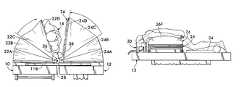
- FIG. 1is an isometric view, partially exploded, of one exemplary embodiment of a patient transport and positioning system constructed in accordance with this invention shown in use on a conventional gurney or stretcher and a conventional operating room table;
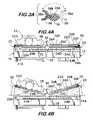
- FIG. 2is a top plan view of the system shown in FIG. 1 , wherein a patient on a gurney or stretch is into position in the operating room for disposition in a prone position on the operating room table;
- FIG. 3is an enlarged end view taken along line 3 — 3 of FIG. 2 ;
- FIG. 3Ais an enlarged transverse sectional view of a portion of the system shown in FIG. 3 ;
- FIG. 4Ais an end view showing the system of FIG. 1 showing the operation of the system of FIG. 1 , namely, with a patient in a supine orientation on the gurney or stretcher ready to be transferred into a prone orientation on the operating room table;
- FIG. 4Bis an end view, like that of FIG. 4A , but showing the system at an early stage in the inflation of its components to effect the transference of the patient;
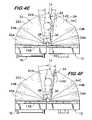
- FIG. 4Cis an end view, like that of FIGS. 4A–4B , but showing the system at a later stage in the inflation of its components to effect the transference of the patient;
- FIG. 4Dis an end view, like that of FIGS. 4A–4C , but showing the system at a still later stage in the inflation of its components to effect the transference of the patient;
- FIG. 4Eis an end view, like that of FIGS. 4A–4D , but showing the system at a still later stage in the inflation of its components to effect the transference of the patient;
- FIG. 4Fis an end view, like that of FIGS. 4A–4E , but showing the system at a still later stage in the inflation of its components to effect the transference of the patient;
- FIG. 4Gis an end view, like that of FIGS. 4A–4F , but showing the system at a still later stage in the inflation of its components to effect the transference of the patient;
- FIG. 4His an end view, like that of FIGS. 4A–4G , but showing the system at a still later stage in the inflation of its components to effect the transference of the patient;
- FIG. 4Iis an end view, like that of FIGS. 4A–4H , but showing the system at a still later stage in the inflation of its components to effect the transference of the patient;
- FIG. 4Jis an end view, like that of FIGS. 4A–4G , but showing the system wherein the patient has been transferred to the operating room table and some components of the system inflated to cause the spine of the prone patient to assume a convex shape suitable for spinal surgery;
- FIG. 5Ais a side elevation view taken along line 5 A— 5 A of FIG. 4I ;
- FIG. 5Bis a side elevation view taken along line 5 B— 5 B of FIG. 4J ;
- FIG. 6is an enlarged sectional view taken along line 6 — 6 of FIG. 2 ;
- FIG. 7is a partial sectional view taken along line 7 — 7 of FIG. 6 ;
- FIG. 8is an enlarged sectional view taken along line 8 — 8 of FIG. 2 ;
- FIG. 9is a partial sectional view taken along line 9 — 9 of FIG. 8 ;
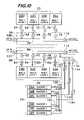
- FIG. 10is a diagram of the various pneumatic components making up the system of FIG. 1 .
- FIG. 1one exemplary embodiment of a patient transport and positioning system for use in a hospital operating room constructed in accordance with this invention.
- the systemcan be used for conducting any type of medical procedure requiring a patient to be in a particular orientation, such as when the patient is under a general anesthetic or intravenous sedation during a surgical procedure, e.g., back surgery.
- the system 20basically comprises two inflatable assemblies 22 and 24 , one of which, 22 , is arranged to be disposed on a conventional patient transport device 10 , such as a stretcher, gurney, litter or the like.
- the other assembly 24is arranged to be disposed on a conventional operating room table 12 .
- the first assembly 22is arranged to support a patient 14 in the supine position on it (see FIG. 2 ) so that the patient can be brought into the operating room, with the stretcher, gurney or whatever transportation device utilized being located immediately laterally beside the operating room table, like shown in FIG. 1 .
- the two assemblies 22 and 24are arranged to be releasably coupled together by means (to be described later) when the stretcher is located immediately adjacent the operating room table as shown in FIGS. 1–3 .
- the top surface of the assembly 22which will be described later, serves to receive the patient thereon in a horizontal supine position. That surface will be referred to as the patient supporting surface.
- the assembly 22is arranged, when operated, to rotate the patient on the patient supporting surface through an arc slightly in excess of 90 degrees about a longitudinal axis X extending between the stretcher 10 and the table 12 to a “patient transfer” position at which the second assembly 24 receives the patient.
- the assembly 24also includes a top surface (to be described later) which is referred to hereinafter as the “patient receiving surface.”
- the assembly 24is arranged to operate in conjunction and coordination with the assembly 22 so that when the patient is rotated to the patient transfer position, that is slightly beyond the vertical orientation, the assembly 24 will receive the patient on its patient receiving surface so that the patient is prone on that surface.
- the assembly 24is further operated to rotate the patient downward until the patient is disposed horizontally.
- the horizontally prone patient on the operating room tableis now in position whereupon surgery can be conducted on the patient's back (or any other portion of the rear of the patient).
- the system 20also includes an additional assembly 26 in the form of plural expandable components (to be described in detail later) for causing the spine of the horizontally prone patient to curve in a downward convex direction, as is commonly required for spinal surgery.
- an additional assembly 26in the form of plural expandable components (to be described in detail later) for causing the spine of the horizontally prone patient to curve in a downward convex direction, as is commonly required for spinal surgery.
- the third assembly(if utilized) is operated to return the patient to the normally generally planar horizontally prone orientation, i.e., to enable the patient's spine to return from the downwardly curved position created by the assembly 26 for the surgery to its normal degree of curvature.
- the stretcher 10is then moved back to the position immediately adjacent laterally the operating room table as shown in FIGS. 1–3 and the two assemblies 22 and 24 are recoupled together.
- the assembly 24 on the operating room table and the assembly 22 on the stretcherare then operated in a similar, albeit reverse, manner as described above to cause the patient to be rotated back from the horizontally prone position on the operating room table 12 to the horizontally supine position on the stretcher 10 .
- the two assemblies 22 and 24 of the systemcan be again uncoupled and the stretcher rolled away to remove the patient from the operating room.
- assemblies 22 and 24 of the system 20may form an integral portion of the stretcher and the operating room table, respectively, or may be arranged to be removably mounted thereon.
- the assembly 22is in the form of plural inflatable members.
- the assembly 24is in the form of plural inflatable members. So, too, if an assembly 26 is utilized, it is also in the form of plural inflatable members. All of the inflatable members are formed of a relatively soft flexible yet strong and airtight material.
- the system 20additionally comprises a manifold assembly 28 , including a pair of housings and associated common manifold pipes (to be described later). Each of these manifold pipes is arranged to be coupled to a source of fluid, e.g., compressed air (not shown).
- a face cradle 30is preferably provided and is located on the operating room table 12 to receive the face of the patient when the patient is in the prone position.
- An optional pair of legs/footrests 32 and 34may also be provided.
- the system 20additionally comprises a fulcrum assembly 36 and a shoulder support 38 .
- the face cradle 30preferably includes an oxygen supply tube and/or other tubes for releasable coupling to the patient's face.
- the optional footrest 32 and 34can be used to support the patient's knees as the patient is supine on the stretcher and to support the patient's feet as the patient is prone on the operating room table.
- the shoulder support 38is coupled to the fulcrum 36 to expedite the rotation of the patient from the horizontal supine position on the stretcher to the horizontal prone position on the operating room table and vice versa, as will be described later.
- the inflatable components of the assembly 22comprise a plurality, e.g., four, inflatable chambers or bags 22 A, 22 B, 22 C and 22 D.
- Each chamberwhen fully inflated is of a wedge shape and flares outward from a short height edge located closely adjacent the inside lateral edge 40 of the stretcher 10 to a long height edge located adjacent the outside lateral edge 42 of the stretcher.
- the chambers 22 A, 22 B, and 22 Care all coextensive in size.
- the topmost chamber 22 Dis slightly smaller in size and its inner marginal edge is located spaced inward from the inner marginal edges of the underlying chambers 22 C, 22 B and 22 A.
- the length of the uppermost chamber 22 Dis also shorter than the underlying chambers 22 C, 22 B and 22 A.
- the chambers 22 C, 22 B and 22 Aare all of the same size and cross-sectional area.
- FIG. 10there is shown a schematic diagram of the assemblies 22 , 24 and 26 .
- the inflatable chambers 22 D, 22 C, 22 B and 22 A of the assembly 22are identified in that diagram as being “bag 1 layer 1 ”, “bag 1 layer 2 ”, “bag 1 layer 3 ”, and “bag 1 layer 4 ”, respectively.
- the lowermost or fourth chamber 22 Ais mounted on a base plate subassembly 44 .
- That subassemblyincludes a top base plate member and a bottom base plate member.
- the bottom base plate memberis secured (fixedly or releasably) to the top of the stretcher 10 .
- the top base plate of the subassembly 44is secured to the bottom base plate by plural screws 46 .
- Each of the chambers 22 A– 22 Dis arranged to be inflated to cause it to extend from its compact flattened state as shown in FIG. 6 to its respective fully expanded wedge shaped states shown in FIG. 4F .
- the inflation of the chambers 22 A– 22 Dis accomplished sequentially starting with chamber 22 A, then chamber 22 B, then chamber 22 C and finally ending with chamber 22 D (as will be described later) to effect the rotation of the patient as mentioned previously.
- the means for inflating the chambersconstitutes compressed air that is provided to the respective chambers of the assembly 22 via the manifold assembly 28 and plural lines and valves.
- the first or uppermost chamber 22 Dincludes a common passageway 48 ( FIGS. 6 and 7 ) in the lateral side portion of that chamber.
- the passageway 48includes plural longitudinally spaced orifices 50 in communication with the interior of the chamber 22 D.
- the passageway 48is connected to one end of a line or conduit 52 .
- the other end of that lineis connected to a valve 54 , which in turn is connected to a common fluid passageway or pipe 56 forming a portion of the manifold assembly 28 .
- the common pipe 56is located within a housing 58 .
- the housing 58 and the common pipe 56forms the manifold for the inflatable assembly 22 and is disposed on the stretcher along the longitudinal lateral edge 40 of the stretcher immediately adjacent the chambers 22 A– 22 D.
- the valve 54is provided to enable fluid, e.g., the compressed air, to either be introduced into the chamber 22 D to inflate it or to enable the air within the chamber to exit the chamber to deflate it.
- the second chamber 22 Cincludes a common passageway 60 having plural longitudinally spaced orifices 62 communicating with the interior of that chamber.
- a valve 64is connected to the passageway 60 via a line 66 .
- the valveis in turn connected to the common manifold pipe 56 to enable compressed air to be introduced from the manifold into the common passageway and out through the orifice 62 in the interior of the chamber 22 C to inflate that chamber.
- the valve 64is also operative to enable the air within the chamber 22 C to pass out through the orifice 62 , the common passageway 60 and the valve 64 back to the manifold pipe to deflate the chamber.
- the chamber 22 Balso includes a common passageway 68 having plural longitudinally spaced orifices (not shown) communicating with the interior of the chamber.
- a valve 70is connected to the passageway 68 via a line 72 .
- the valve 72is in turn connected to the common manifold pipe 56 to enable the chamber 22 B to be inflated and deflated in the same manner as chambers 22 D and 22 C.
- the fourth or lowermost of the chambers 22 Aincludes a common passageway 74 having plural longitudinally spaced orifices (not shown) in communication with the interior of that chamber.
- a valve 76is connected to the passageway 74 via a line 78 .
- the valveis in turn connected to the common manifold pipe 56 so that the chamber can also be inflated and deflated in the same manner as
- the inflatable assembly 24also includes plural, e.g., four chambers or bags 24 A, 24 B, 24 C and 24 D, that are similar in construction to the chambers or bags 22 A– 22 D except that each of the chambers or bags 24 A– 24 D is of the same size and shape.
- the inflatable chambers 24 D, 24 C, 24 B and 24 Aare identified in FIG. 10 as “bag 2 layer 1 ”, “bag 2 layer 2 ”, “bag 2 layer 3 ” and “bag 2 layer 4 ”, respectively. This represents that chamber 24 A is the fourth or lowermost chamber, that chamber 24 B is the third or next lowermost chamber, that chamber 24 C is the second or next uppermost chamber and that chamber 24 D is the first or topmost chamber.
- Each chamber 24 A– 24 Dis constructed so that it can be inflated from its generally flat condition shown in FIGS. 1 and 8 to a fully inflated wedge shaped condition.
- the fully wedge shaped condition of the topmost or first chamber 24 Ais not shown, but is similar to that of the topmost chamber 24 A. This maximum inflation of chamber 24 A occurs during the transfer of the patient back to the stretcher after the surgery has been completed, as will be described later.
- the lowermost or fourth chamber 24 A of the inflatable assembly 24is mounted on a top base plate of another base plate subassembly 44 .
- That subassemblyis identical in construction to the one discussed earlier except that its bottom base plate is mounted on the top surface of the operating room table.
- the top base plateis secured to the bottom base plate via plural screws 46 .
- the first or uppermost chamber 24 Dincludes a longitudinally extending passageway 80 .
- This passagewayincludes a plurality of longitudinally spaced orifices (not shown) communicating with the interior of the chamber 24 D.
- a valve 82is connected to the passageway 80 via a line 84 .
- the valveis connected to a common manifold pipe 86 .
- This pipeforms another portion of the manifold assembly 28 .
- the common pipe 86is located within a housing 88 . That pipe and housing form the manifold for the inflatable assembly 24 .
- the valve 82enables the chamber 24 D to be inflated and deflated in a manner similar to that described above.
- the chamber 24 Cincludes a longitudinally extending passageway 90 having a plurality of longitudinally spaced orifices (not shown) communicating with the interior of the chamber 24 C.
- a valve 92is connected to the passageway 90 via a line 94 .
- the valve 92is connected to the common manifold pipe 86 .
- the valve 92enables the chamber 24 C to be inflated and deflated in a similar manner to chamber 24 D.
- the chamber 24 Bincludes a longitudinally extending passageway 96 in it. This passageway includes a plurality of longitudinally spaced orifices (not shown) in communication with the interior of the chamber 24 B.
- the valve 98is connected to the passageway 96 via line 100 .
- the valve 98is connected to the common manifold pipe 86 to enable the chamber 24 B to be inflated and deflated in a manner similar to chamber 24 C.
- the fourth or lowermost chamber 24 Aincludes a longitudinally extending passageway 102 having a plurality of longitudinally spaced orifices (not shown) in communication with the interior of that chamber.
- a valve 104is connected to the passageway 102 via a line 106 .
- the valve 104is connected to the common manifold pipe 86 to enable the chamber 22 A to be inflated and deflated in a manner similar to chamber 22 B.
- the manifold housing 88 for the inflatable assembly 24is mounted adjacent the inside lateral edge 40 of the operating room table.
- the wedge shaped chambers 24 A– 24 Dare oriented on the operating room table in the same manner as the chambers 22 A– 22 D of the inflatable assembly 22 .
- the chambers 24 A– 24 Dflare upward from a short height edge located closely adjacent the inside lateral edge of the table 12 to a long height edge located adjacent the outside lateral edge 42 of the table.
- the manifold associated with the inflatable assembly 22also includes an “inlet” valve 108 connected to the inlet end of the common manifold pipe 56 . It is at this end where compressed air is supplied via a conduit from a source of compressed air (not shown).
- Another valve 110is connected at the opposite or vent end of the common manifold pipe. The valve 110 serves as a “vent” valve to vent air in it to the ambient atmosphere, as will be described later.
- the manifold associated with inflatable assembly 24also includes an “inlet” valve 112 connected at the inlet end of the common manifold pipe 86 .
- vent valve 114is connected to the opposite or vent end of the common manifold pipe 86 . This valve 114 serves as the vent valve to vent the air in common manifold pipe 86 to the ambient atmosphere.
- the closing of the vent valve 110 and the opening of the inlet valve 108 of the manifold associated with the inflatable assembly 22enables compressed air to flow into the common manifold pipe 56 .
- the sequential opening of the valves 76 , 70 , 64 and 54 of that assemblycauses the chambers 22 A, 22 B, 22 C and 22 D, respectively, to inflate in sequence.
- the closing of the vent valve 114 and the opening of the valve 112 of the manifold associated with the inflatable assembly 24enables compressed air to flow into the common manifold pipe 86 of that assembly.
- the sequential opening of the valves 104 , 98 , 92 and 82causes the chambers 24 A, 24 B, 24 C and 24 D, respectively, to inflate in sequence.
- the opening of the vent valve 110 and the closing of the inlet valve 108 of the manifold associated with the inflatable assembly 22enables its chambers to be deflated in sequence.
- the opening of the valves 54 , 64 , 70 and 76cause the air in chambers 22 D, 22 C, 22 B and 22 A, respectively, to vent out the open vent valve 110 .
- the opening of the vent valve 114 and the closing of the inlet valve 112 of the manifold associated with the inflatable assembly 22enables its chambers to be deflated in sequence.
- the opening of valves 82 , 92 , 98 and 104causes the air in chambers 24 D, 24 C, 24 B and 24 A, respectively, to vent through the open vent valve 114 .
- the shoulder support 38basically comprises an elongated crescent shaped member formed of a somewhat rigid material, e.g., plastic.
- the crescent shaped memberhas a relatively soft inner pad or liner 38 extending along its length.
- the shoulder support 38includes a pivot pin 38 B mounted on its outer surface. The pin 38 B is arranged to be located within an arcuate slot 36 A in the fulcrum 36 .
- the fulcrum 36is itself an elongated linear member of generally oval cross-sectional shape and of a relatively rigid material.
- the fulcrumis located and disposed on top of the two longitudinally extending manifold housings 58 and 88 as clearly shown in FIGS. 1 and 4A .
- the shoulder support 38is arranged to be pivoted from the orientation should in FIG. 3A through an arc about the fulcrum 36 in the direction of the arrow in FIG. 3A to move from the leftmost position wherein the supine patient is on the stretcher to the rightmost position (shown in phantom lines) wherein the patient is on the operating table in a horizontal prone orientation.
- the fulcrum and associated padcooperate with the inflatable components of the inflatable assemblies 22 and 24 to effect the smooth and safe transfer of the patient from the horizontal supine position on the stretcher to the horizontal prone position on the operating table and then back to the horizontal supine position on the stretcher after the surgery is completed.
- the system 20includes a pair of locking bars 116 and 118 .
- Each locking barcomprises an elongated member having plural projections 120 extending therefrom. The projections are arranged to extend into associated aligned holes in the base 44 of the inflatable assembly 22 located on the stretcher 10 and into associated aligned holes in the base 44 of the inflatable assembly 24 located on the operating room table.
- the system 20can be operated to effect a transfer and rotation of the patient. This operation will be described with reference to FIGS. 4A–4H .
- FIG. 4Ait can be seen that the patient is in a horizontally supine position on the top surface of the top inflatable chamber 22 D, with his or her shoulder and contiguous upper arm located within the shoulder support.
- the top surface of the assembly 24includes a heretofore identified third inflatable assembly 26 . The details of that assembly will be described later.
- the outlet valves 110 and 114are closed and the inlet valves 108 and 112 are open.
- all of the valves 54 , 64 , 70 and 76 of the inflatable assembly 22are closed as are all of the valves 82 , 92 , 98 and 104 of the inflatable assembly 24 .
- valves 76 and 104 of the assemblies 22 and 24are opened, whereupon compressed air is enabled to flow through common manifold pipe 56 and valve 76 into line 78 and from there into the interior of the chamber 22 A, thereby causing that chamber to inflate to its wedge shaped condition like shown in FIG. 4B .
- valve 104 of the inflatable assembly 24is opened, whereupon the compressed air flows from the common manifold pipe 86 through that valve and line 106 into the interior of the chamber 24 A, thereby causing that chamber to assume the wedge shaped condition shown in FIG. 4B .
- valve 70 of the first inflatable assembly 22is opened, whereupon the compressed air in the common manifold pipe 56 is enabled to flow through that valve and through line 72 into the interior of the chamber 22 B thereby causing that chamber to inflate to its wedge shape condition shown in FIG. 4C .
- valve 98 of the second inflatable assembly 24is opened, whereupon compressed air in the common manifold pipe 86 is enabled to flow through that valve and line 100 into the interior of the chamber 24 B, thereby causing that chamber to assume its wedge shaped condition as shown in FIG. 4C .
- Valve 64 of the first inflatable assembly 22is then opened, whereupon compressed air in common manifold pipe 56 is enabled to flow through that valve and line 66 into the interior of chamber 22 C to cause that chamber to inflate to its wedge shaped condition as shown in FIG. 4D .
- the valve 92 in the inflatable assembly 24is opened, whereupon compressed air in the common manifold pipe 86 is enabled to flow through that valve and line 94 into the interior of chamber 24 C. This action causes that chamber to inflate to its wedge shaped condition shown in FIG. 4D .
- the inflation of the chambers as described heretoforeresults in the pivoting of the patient about the fulcrum to a point where the patient is almost in a vertical orientation.
- Valve 54 of the inflatable assembly 22is then opened, thereby enabling compressed air in common manifold pipe 56 to flow through it and line 52 into the chamber 22 D.
- This actioncauses the chamber 22 D to start to inflate to the wedge shaped condition shown in FIG. 4E , whereupon the patient is in a vertical orientation.
- the valve 82 of the inflatable assembly 24is opened to enable compressed air in the manifold pipe 86 to flow through that valve and line 84 into the interior of chamber 24 D.
- This actioncauses that chamber to partially inflate as shown in FIG. 4E , whereupon the patient receiving surface, that is the top surface of the assembly 24 , engages the chest of the patient while the patient is in the vertical upright position.
- the valve 54 of the assembly 22remains open, thereby enabling the chamber 22 D to inflate further to the fully expanded wedge shaped condition shown in FIG. 4F .
- the valves 64 , 70 and 76are closed so that the chambers associated with them remain inflated.
- the valves 92 , 98 and 104are also closed to ensure that the chambers 24 C, 24 B and 24 A remain inflated.
- the inlet valve 112is closed, the outlet valve 114 is opened and the valve 82 is opened whereupon the air in chamber 24 D vents through line 84 , valve 82 , common manifold pipe 86 and valve 114 to the ambient atmosphere so that the chamber 24 D collapses whereupon the patient is rotated to the patient transfer position just slightly in excess of 90 degrees as shown in FIG. 4F .
- the center of gravity of the patientis slightly beyond the vertical plane so that a portion of the patient's weight is now being supported by the engaged top or patient receiving surface of the inflatable assembly 24 .
- the patientis now facing prone on the patient receiving surface of the inflatable assembly 24 .
- the inlet valve 108 of the assembly 22is then closed and the outlet valve 110 of that assembly is then opened, whereupon the air within chamber 22 D flows through line 52 , open valve 54 , common manifold conduit 56 and outlet vent valve 110 to the ambient atmosphere, thereby enabling the bag 22 to deflate as shown in FIG. 4G .
- the valve 92 of the inflatable assembly 24is opened, whereupon the air within chamber 24 C vents from that chamber through line 94 and valve 92 into the common manifold line 86 and out through the outlet valve 114 to the ambient atmosphere so that the chamber 24 C is now collapsed thereby bringing the patient to the position shown in FIG. 4G .
- valves 64 and 70 of the inflatable assembly 22can then be opened, whereupon the air within chamber 22 flows out of that chamber through line 66 , open valve 64 , common conduit 56 and open vent 110 to the ambient atmosphere, thereby deflating that chamber.
- the opening of valve 70causes the air within chamber 22 B to flow out of that chamber through line 72 , open valve 70 , common conduit pipe 56 and open outlet valve 110 to the ambient atmosphere, thereby causing that chamber to collapse to the position shown in FIG. 4H .
- valve 76 of the inflatable assembly 22is then opened, whereupon the air within its associated chamber 22 A flows into lines 78 , through open valve 76 , into common conduit pipe 56 and out through outlet valve 110 to the ambient atmosphere, whereupon that chamber assumes its fully flattened state so that the entire assembly 22 is in the state shown in FIG. 4I .
- valve 104 of the inflatable assembly 24is opened, whereupon air in chamber 24 A flows through line 106 , open valve 104 , common manifold pipe 86 to the open outlet valve 114 and hence to the ambient atmosphere.
- This actioncauses the chamber 24 A to flatten out, whereupon the entire inflatable assembly 24 is in its compact or flattened condition shown in FIG. 4I . In this condition the patient is now fully horizontal and prone on the operating room table.
- the patient's faceis supported in the face cradle 30 .
- the shoulder supportcan now be removed from its engagement with the fulcrum so that the patient's shoulder is not restrained.
- That inflatable assemblycomprises a plurality of inflatable chambers, to be described later, that are inflated in sequence so that they cause the patient to be oriented from the flattened horizontally prone position shown in FIG. 5A to the arcuate chest and pelvic orientation shown in FIG. 5B .
- the face cradleholds the patient's head at a desired angular orientation so as not to interrupt the flow of gases and fluids or otherwise interrupt the patient's respiration.
- that assemblybasically comprises a plurality of longitudinally extending narrow elongated chambers or bladders 26 A, 26 B, 26 C, 26 D, 26 E and 26 F.
- the outermost pair of bladders, namely, 26 A and 26 F,are located on the topmost chamber 24 D of the assembly 24 and are located along the respective outside edges of that chamber.
- each of the bladders 26 A and 26 Fextends the full length of the chamber 24 D.
- the next innermost pair of bladders, namely, bladders 26 B and 26 Eare disposed inward of bladders 26 A and 26 F, respectively, on the top of the chamber 24 D.
- the bladders 26 B and 26 Eform an intermediate pair and do not extend the full length of the chamber 24 D, but rather terminate slightly before the rear edge of that chamber 24 D as best seen in FIG. 1 .
- the innermost pair of the bladders, namely, bladders 26 C and 26 Dare located inward of the intermediate bladders 26 B and 26 E, respectively.
- the innermost pair of bladders 26 C and 26 Dare of a shorter length than the intermediate pair of bladders 26 B and 26 E so that they terminate even further from the edge of the chamber 24 D.
- the arrangement of the gradually shortening length bladdersprovides an area for comfortable receipt of the patient's pelvic region.
- the bladders 26 A and 26 Fwhich form the outer pair of bladders are arranged to be inflated in unison. When inflated, the bladders 26 A and 26 F extend to a maximum height as shown in FIG. 4J . This height is higher or the same height as the height of the maximum inflation of the bladder pair 26 B and 26 E. That pair of bladders is also inflated in unison.
- the innermost pair of the bladders 26 C and 26 Dis also arranged to be inflated in unison and when inflated extend to a maximum height which is less than the height of the bladders 26 B and 26 E. Accordingly, when the bladders of the inflatable assembly 26 are inflated as shown in FIG. 4J , the patient is supported outside inward toward the patient's center line. In fact, since the bladders 26 C and 26 D are spaced from each other the central portion of the patient is unsupported. That is, the patient is not supported along his/her center line so that there is an area of decompression along the center line of the patient.
- the amount of inflation of the various bladder pairs of the inflatable assembly 26is adjustable to accommodate patients of various sizes and shapes.
- the inflation and deflation of the bladders 26 A– 26 Fis effected via various valve and lines coupled to the common manifold pipe 86 of the inflatable assembly 24 .
- a pair of branch lines 130 and 132are connected to the bladders 26 C and 26 D, respectively, via orifices in communication with the interior of the innermost bladders 26 C and 26 D, respectively.
- the branch lines 132merge with a common line 134 connected to one side of a valve 136 .
- the other side of the valveis connected to the common manifold pipe 86 .
- a pair of branch lines 138 and 140are connected to the intermediate bladders 26 B and 26 E, respectively, via orifices in communication with those bladders to a common line 142 .
- the line 142is connected to one side of a valve 144 .
- the other side of the valve 144is connected to the common manifold pipe 86 .
- a pair of branch lines 146 and 148is connected to the bladders 26 A and 26 F, respectively, via orifices in communication with those bladders.
- the branch lines 146 and 148merge into a common line 150 connected to one side of a valve 152 .
- the other side of valve 152is connected to the common manifold pipe 86 .
- the inflation of the bladders of assembly 26is accomplished in pairs.
- the air outlet valve 114is closed, the air inlet valve 112 is open and the valves 82 , 92 , 98 and 104 are closed.
- the valve 152 of the inflatable assembly 26is then opened, whereupon compressed air flows through the line 150 and the communicating branch lines 146 and 148 into the bladders 26 A and 26 F to effect their inflation in unison.
- the valve 144is then opened, whereupon the compressed air in the common manifold pipe 86 flows through that valve and common line 142 into branch lines 138 and 140 .
- the bladders of the assembly 26are deflated by opening the outlet valve 114 , closing off the compressed air inlet valve 112 and then opening the valves 152 , 144 and 136 of the assembly 26 .
- This actioncauses the air in the pair of bladders 26 A and 26 F to flow through branch lines 146 and 148 , respectively, into common line 150 , through valve 152 into the common manifold pipe 86 and out through the open vent valve 114 .
- air from bladders 26 B and 26 Eflows through the branch lines 138 and 140 , respectively, into the common line 142 , through open valve 144 into the common manifold pipe 86 and out through the open vent valve 114 .
- the bladders 26 C and 26 Dare deflated by opening the valve 136 , whereupon the air in those bladders flows through the branch lines 130 and 132 into the common line 134 , through open valve 136 and into the common manifold pipe 86 and out through the open vent valve 114 .
- the patientis now ready to be transferred back to the stretcher 10 for removal from the operating room.
- the stretcher bearing the inflatable assembly 22is brought back into position immediately alongside the operating room table like shown in FIG. 2 .
- the inflatable assemblies 22 and 24are then operated in the reverse manner as described above to effect the pivoting of the patient from the horizontal prone position on the operating table back to the horizontal supine position on the stretcher.
- the sequence of operationis virtually the same as that described with reference to transferring the patient from the stretcher to the operating table.
- the fourth or uppermost chamber 24 D of the assembly 24is inflated to a fully inflated position whereupon the center of gravity of the patient will be on the opposite side of the vertical plane that is shown in FIG. 4 , i.e., a portion of the patient's weight will be disposed on the patient supporting surface of the chamber 22 D of the inflatable assembly 22 .
- any suitable meanscan be used to control the various valves and the supply of compressed air, such as a computer or some other controller (not shown).
- a computer or some other controllernot shown.
- the exact sequence of operationneed not be precisely as described so long as the patient is rotated in a safe manner about the axis X to transfer him/her from the stretcher to the laterally disposed operating room table and then back to the stretcher after the surgery.
- the patient transport system of this inventionis shown to preferably include the inflatable assembly 26 , the use of such an assembly is not mandatory. Thus, if for some surgery it is not required to cause the patient's spine to be in a downward arcuate shape like shown in FIG. 5B , the system need not include the third inflatable components. It should also be pointed out the system while being disclosed as being operated pneumatically can be operated hydraulically. Further still, the number and orientation and shape of the various inflatable chambers is a matter of choice and thus the specific number and arrangement shown is merely exemplary. Further still, the various inflatable compartments or components can be fixedly secured to one another, such as shown, or can be releasably secured to one another.
- the inflation and deflation of the inflatable components of the present inventionis preferably achieved via pneumatic, i.e., compressed air, control.
- pneumatici.e., compressed air
- hydraulici.e., liquid
- electronic controle.g., using electronic actuators
- any combination of pneumatic, hydraulic and electronic controlfor controlling the inflation and deflation of the inflatable components.
Landscapes
- Health & Medical Sciences (AREA)
- Public Health (AREA)
- Biomedical Technology (AREA)
- Life Sciences & Earth Sciences (AREA)
- Animal Behavior & Ethology (AREA)
- General Health & Medical Sciences (AREA)
- Engineering & Computer Science (AREA)
- Veterinary Medicine (AREA)
- Orthopedic Medicine & Surgery (AREA)
- Neurology (AREA)
- Neurosurgery (AREA)
- Nursing (AREA)
- Accommodation For Nursing Or Treatment Tables (AREA)
Abstract
Description
Claims (36)
Priority Applications (3)
| Application Number | Priority Date | Filing Date | Title |
|---|---|---|---|
| US10/866,852US6966081B1 (en) | 2004-06-14 | 2004-06-14 | Transport and positioning system for use in hospital operating rooms |
| PCT/US2005/020272WO2005122992A2 (en) | 2004-06-14 | 2005-06-09 | Transport and positioning system for use in hospital operating rooms |
| US11/294,608US7197778B2 (en) | 2004-06-14 | 2005-11-19 | Patient transfer system |
Applications Claiming Priority (1)
| Application Number | Priority Date | Filing Date | Title |
|---|---|---|---|
| US10/866,852US6966081B1 (en) | 2004-06-14 | 2004-06-14 | Transport and positioning system for use in hospital operating rooms |
Related Child Applications (1)
| Application Number | Title | Priority Date | Filing Date |
|---|---|---|---|
| US11/294,608Continuation-In-PartUS7197778B2 (en) | 2004-06-14 | 2005-11-19 | Patient transfer system |
Publications (2)
| Publication Number | Publication Date |
|---|---|
| US6966081B1true US6966081B1 (en) | 2005-11-22 |
| US20050273926A1 US20050273926A1 (en) | 2005-12-15 |
Family
ID=35344725
Family Applications (2)
| Application Number | Title | Priority Date | Filing Date |
|---|---|---|---|
| US10/866,852Expired - LifetimeUS6966081B1 (en) | 2004-06-14 | 2004-06-14 | Transport and positioning system for use in hospital operating rooms |
| US11/294,608Expired - LifetimeUS7197778B2 (en) | 2004-06-14 | 2005-11-19 | Patient transfer system |
Family Applications After (1)
| Application Number | Title | Priority Date | Filing Date |
|---|---|---|---|
| US11/294,608Expired - LifetimeUS7197778B2 (en) | 2004-06-14 | 2005-11-19 | Patient transfer system |
Country Status (2)
| Country | Link |
|---|---|
| US (2) | US6966081B1 (en) |
| WO (1) | WO2005122992A2 (en) |
Cited By (47)
| Publication number | Priority date | Publication date | Assignee | Title |
|---|---|---|---|---|
| EP1820483A3 (en)* | 2006-02-17 | 2007-10-03 | Kensington Healthcare Ventures, LLC | Rotational operating table |
| US20080034495A1 (en)* | 2006-01-06 | 2008-02-14 | Stidd Raymond E | Patient gurney |
| US20080222811A1 (en)* | 2006-01-05 | 2008-09-18 | Jan Gilbert | Rotational Operating Table |
| US20100192300A1 (en)* | 2008-10-28 | 2010-08-05 | Tannoury Tony Y | Prone and laterally angled surgical device and method |
| US20100257673A1 (en)* | 2009-04-08 | 2010-10-14 | Linares Miguel A | Combination medical support table & portable convertible stretcher unit |
| US20100313353A1 (en)* | 2009-06-12 | 2010-12-16 | Bedlab, Llc | Stretcher Accessory for Turning a Patient |
| US20140007353A1 (en)* | 2012-04-30 | 2014-01-09 | Stryker Corporation | Patient turner |
| US20150157521A1 (en)* | 2013-12-06 | 2015-06-11 | Hill-Rom Services, Inc. | Inflatable Patient Positioning Unit |
| US9072646B2 (en) | 2010-12-14 | 2015-07-07 | Allen Medical Systems, Inc. | Lateral surgical platform with rotation |
| US9498397B2 (en) | 2012-04-16 | 2016-11-22 | Allen Medical Systems, Inc. | Dual column surgical support system |
| US9655793B2 (en) | 2015-04-09 | 2017-05-23 | Allen Medical Systems, Inc. | Brake release mechanism for surgical table |
| US20180344309A1 (en)* | 2012-09-17 | 2018-12-06 | DePuy Synthes Products, Inc. | Systems and methods for surgical and interventional planning, support, post-operative follow-up, and functional recovery tracking |
| US10363189B2 (en) | 2015-10-23 | 2019-07-30 | Allen Medical Systems, Inc. | Surgical patient support for accommodating lateral-to-prone patient positioning |
| US10492973B2 (en) | 2015-01-05 | 2019-12-03 | Allen Medical Systems, Inc. | Dual modality prone spine patient support apparatuses |
| US10548796B2 (en) | 2015-08-17 | 2020-02-04 | Warsaw Orthopedic, Inc. | Surgical frame and method for use thereof facilitating articulatable support for a patient during surgery |
| US10548793B2 (en) | 2016-06-14 | 2020-02-04 | Allen Medical Systems, Inc. | Pinless loading for spine table |
| US10561559B2 (en) | 2015-10-23 | 2020-02-18 | Allen Medical Systems, Inc. | Surgical patient support system and method for lateral-to-prone support of a patient during spine surgery |
| US10576006B2 (en) | 2017-06-30 | 2020-03-03 | Warsaw Orthopedic, Inc. | Surgical frame having translating lower beam and method for use thereof |
| US10729507B2 (en) | 2017-01-12 | 2020-08-04 | Warsaw Orthopedic, Inc. | Surgical draping system and method for using same |
| US10835439B2 (en) | 2018-08-21 | 2020-11-17 | Warsaw Orthopedic, Inc. | Surgical frame having translating lower beam and moveable linkage or surgical equipment attached thereto and method for use thereof |
| US10857054B2 (en) | 2015-11-13 | 2020-12-08 | Allen Medical Systems, Inc. | Person support apparatuses for subject repositioning |
| US10874570B2 (en) | 2017-06-30 | 2020-12-29 | Warsaw Orthopedic, Inc. | Surgical frame and method for use thereof facilitating patient transfer |
| US10881570B2 (en) | 2019-04-26 | 2021-01-05 | Warsaw Orthopedic, Inc | Reconfigurable pelvic support for a surgical frame and method for use thereof |
| US10888484B2 (en) | 2019-04-26 | 2021-01-12 | Warsaw Orthopedic, Inc | Reconfigurable pelvic support for surgical frame and method for use thereof |
| US10893996B2 (en) | 2018-08-22 | 2021-01-19 | Warsaw Orthopedic, Inc. | Surgical frame having translating lower beam and moveable linkage or surgical equipment attached thereto and method for use thereof |
| US10898401B2 (en) | 2018-08-22 | 2021-01-26 | Warsaw Orthopedic, Inc. | Reconfigurable surgical frame and method for use |
| US10900448B2 (en) | 2017-03-10 | 2021-01-26 | Warsaw Orthopedic, Inc. | Reconfigurable surgical frame and method for use thereof |
| CN112274373A (en)* | 2018-12-26 | 2021-01-29 | 河南科技大学第一附属医院 | Body position frame for medical field |
| US10940072B2 (en) | 2016-10-28 | 2021-03-09 | Warsaw Orthopedic, Inc. | Surgical table and method for use thereof |
| US10966892B2 (en) | 2015-08-17 | 2021-04-06 | Warsaw Orthopedic, Inc. | Surgical frame facilitating articulatable support for a patient during surgery |
| US11020304B2 (en) | 2017-08-08 | 2021-06-01 | Warsaw Orthopedic, Inc. | Surgical frame including main beam for facilitating patient access |
| WO2021211590A1 (en)* | 2020-04-13 | 2021-10-21 | Children's Medical Center Corporation | Patient positioning |
| US11202731B2 (en) | 2018-02-28 | 2021-12-21 | Allen Medical Systems, Inc. | Surgical patient support and methods thereof |
| US11213448B2 (en) | 2017-07-31 | 2022-01-04 | Allen Medical Systems, Inc. | Rotation lockout for surgical support |
| US11224548B2 (en)* | 2016-09-05 | 2022-01-18 | Ergotrics N.V. | System and method for rotating a patient |
| US11229572B1 (en)* | 2020-11-03 | 2022-01-25 | Chima Iku | Adjustable therapist table |
| US11234886B2 (en) | 2019-09-25 | 2022-02-01 | Warsaw Orthopedic, Inc. | Reconfigurable upper leg support for a surgical frame |
| US11304867B2 (en) | 2020-04-22 | 2022-04-19 | Warsaw Orthopedic, Inc. | Lift and method for use of a lift for positioning a patient relative to a surgical frame |
| US11471354B2 (en) | 2018-08-30 | 2022-10-18 | Allen Medical Systems, Inc. | Patient support with selectable pivot |
| US11813217B2 (en) | 2020-04-22 | 2023-11-14 | Warsaw Orthopedic, Inc | Lift and method for use of a lift for positioning a patient relative to a surgical frame |
| US11925586B2 (en) | 2022-03-25 | 2024-03-12 | Mazor Robotics Ltd. | Surgical platform and trolley assembly |
| US12150902B2 (en) | 2022-05-10 | 2024-11-26 | Warsaw Orthopedic, Inc. | Surgical table |
| US12207946B2 (en) | 2022-05-10 | 2025-01-28 | Warsaw Orthopedic, Inc. | Surgical platform system |
| US12213905B2 (en) | 2022-05-10 | 2025-02-04 | Warsaw Orthopedic, Inc. | Surgical platform system |
| US12239584B2 (en) | 2022-06-22 | 2025-03-04 | Warsaw Orthopedic, Inc. | Interface moveably interconnecting surgical table and gantry |
| US20250161131A1 (en)* | 2023-11-21 | 2025-05-22 | Nicholas Williams | Air controlled pressure off loading devices |
| US12396909B2 (en) | 2022-08-29 | 2025-08-26 | Warsaw Orthopedic, Inc. | Surgical platform system |
Families Citing this family (37)
| Publication number | Priority date | Publication date | Assignee | Title |
|---|---|---|---|---|
| US9186291B2 (en) | 2005-02-22 | 2015-11-17 | Roger P. Jackson | Patient positioning support structure with trunk translator |
| US9301897B2 (en) | 2005-02-22 | 2016-04-05 | Roger P. Jackson | Patient positioning support structure |
| US20150059094A1 (en) | 2005-02-22 | 2015-03-05 | Roger P. Jackson | Patient positioning support structure |
| US8844077B2 (en)* | 2005-02-22 | 2014-09-30 | Roger P. Jackson | Syncronized patient elevation and positioning apparatus positioning support systems |
| US9308145B2 (en) | 2005-02-22 | 2016-04-12 | Roger P. Jackson | Patient positioning support structure |
| US9295433B2 (en) | 2005-02-22 | 2016-03-29 | Roger P. Jackson | Synchronized patient elevation and positioning apparatus for use with patient positioning support systems |
| US9744087B2 (en) | 2005-02-22 | 2017-08-29 | Roger P. Jackson | Patient support apparatus with body slide position digitally coordinated with hinge angle |
| US9265679B2 (en) | 2005-02-22 | 2016-02-23 | Roger P Jackson | Cantilevered patient positioning support structure |
| US7565708B2 (en) | 2005-02-22 | 2009-07-28 | Jackson Roger P | Patient positioning support structure |
| US9468576B2 (en) | 2005-02-22 | 2016-10-18 | Roger P. Jackson | Patient support apparatus with body slide position digitally coordinated with hinge angle |
| US7739762B2 (en) | 2007-10-22 | 2010-06-22 | Mizuho Orthopedic Systems, Inc. | Surgery table apparatus |
| US8707484B2 (en) | 2005-02-22 | 2014-04-29 | Roger P. Jackson | Patient positioning support structure |
| US9642760B2 (en) | 2006-05-05 | 2017-05-09 | Roger P. Jackson | Patient positioning support apparatus with virtual pivot-shift pelvic pads, upper body stabilization and fail-safe table attachment mechanism |
| US9339430B2 (en)* | 2006-05-05 | 2016-05-17 | Roger P. Jackson | Patient positioning support apparatus with virtual pivot-shift pelvic pads, upper body stabilization and fail-safe table attachment mechanism |
| US10869798B2 (en) | 2006-05-05 | 2020-12-22 | Warsaw Orthopedic, Inc. | Patient positioning support apparatus with virtual pivot-shift pelvic pads, upper body stabilization and fail-safe table attachment mechanism |
| US20090106893A1 (en)* | 2007-10-30 | 2009-04-30 | Jerry Blevins | Inflatable air mattress for rotating patients |
| US8381331B2 (en)* | 2009-04-01 | 2013-02-26 | Operating Room Safety Enterprises, LLC | Patient-rotation system with center-of-gravity assembly |
| US8707476B2 (en) | 2009-04-01 | 2014-04-29 | Operating Room Safety Enterprises, LLC | Apparatuses for posterior surgery |
| DE102009039367A1 (en)* | 2009-08-29 | 2011-03-03 | Göddert, Marco | Bed in support of the erection |
| USD663427S1 (en) | 2010-10-14 | 2012-07-10 | Operating Room Safety Enterprises, LLC | Torso-support apparatus |
| USD645967S1 (en)* | 2010-10-14 | 2011-09-27 | Patient Safety Transport Systems, Llc | Patient-support frame |
| WO2013058806A1 (en) | 2011-10-17 | 2013-04-25 | Jackson Roger P | Patient positioning support structure |
| US9561145B2 (en) | 2012-02-07 | 2017-02-07 | Roger P. Jackson | Fail-safe release mechanism for use with patient positioning support apparati |
| US9265680B2 (en) | 2012-03-06 | 2016-02-23 | Operating Room Safety Enterprises, LLC | Surgical table |
| US9474671B2 (en) | 2012-03-06 | 2016-10-25 | Operating Room Safety Enterprises, LLC | Surgical table |
| USD745971S1 (en) | 2013-03-06 | 2015-12-22 | Operating Room Safety Enterprises, LLC | Surgical table |
| USD720076S1 (en) | 2013-03-06 | 2014-12-23 | Operating Room Safety Enterprises, LLC | Surgical table |
| US12011399B2 (en) | 2013-08-28 | 2024-06-18 | Warsaw Orthopedic, Inc. | Patient positioning support apparatus with fail-safe connector attachment mechanism |
| US9402775B2 (en) | 2014-07-07 | 2016-08-02 | Roger P. Jackson | Single and dual column patient positioning and support structure |
| US9549863B2 (en) | 2014-07-07 | 2017-01-24 | Roger P. Jackson | Surgical table with pivoting and translating hinge |
| CN104739607B (en)* | 2015-04-21 | 2017-03-22 | 童春平 | Multifunctional critical care system |
| US10426684B2 (en) | 2015-06-11 | 2019-10-01 | Allen Medical Systems, Inc. | Person support apparatuses including person repositioning assemblies |
| CN211797334U (en) | 2018-08-31 | 2020-10-30 | 希尔-罗姆服务公司 | Patient rotation system |
| CN110478151B (en)* | 2019-09-04 | 2021-03-12 | 南通大学附属医院 | Severe patient bathing bed convenient for turning over for long-term bedridden patient |
| CN110742747B (en)* | 2019-10-21 | 2021-02-12 | 南通市第二人民医院 | A patient-friendly turning transfer bed |
| CN114145926B (en)* | 2021-12-06 | 2023-02-17 | 上海市第二康复医院(上海市宝山区一钢医院) | Patient turning bed |
| US20230329931A1 (en)* | 2022-04-18 | 2023-10-19 | Hill-Rom Services, Inc. | Surface adaptation for patient proning |
Citations (18)
| Publication number | Priority date | Publication date | Assignee | Title |
|---|---|---|---|---|
| US3485240A (en)* | 1967-03-15 | 1969-12-23 | Edmund M Fountain | Hospital bed with inflatable patient turning means |
| US3775781A (en)* | 1971-10-15 | 1973-12-04 | J Bruno | Patient turning apparatus |
| US4807313A (en) | 1985-12-03 | 1989-02-28 | Ryder International Corporation | Inflatable inclined mattress support system |
| US4977629A (en)* | 1988-03-15 | 1990-12-18 | Jones Betty J | Portable inflatable patient assist apparatus |
| US5005232A (en) | 1990-08-01 | 1991-04-09 | Inventive Products, Inc. | Patient shifter pad |
| US5073999A (en) | 1989-05-22 | 1991-12-24 | Ssi Medical Services, Inc. | Method for turning a patient with a low air loss patient support |
| US5092007A (en) | 1991-02-21 | 1992-03-03 | Hasty Charles E | Air mattress overlay for lateral patient roll |
| US5412823A (en) | 1993-02-26 | 1995-05-09 | C.A.T. Di Corsini Guiseppe & C. S.P.A. | Patient's examination table for carrying out medical examinations |
| US5506012A (en) | 1994-04-01 | 1996-04-09 | Engineered Fabrics Corp. | Multiple chambered lift bag |
| US5774917A (en)* | 1997-06-20 | 1998-07-07 | Liu; Antony Ching-Fong | Turn mattress inherently formed with side guards |
| US6070281A (en) | 1997-04-18 | 2000-06-06 | Siemens Aktiengesellschaft | Patient orientation table |
| US6085372A (en)* | 1997-10-31 | 2000-07-11 | James; Ingrid B. | Anti-decubitus pneumatic mattress |
| US6119292A (en)* | 1997-07-14 | 2000-09-19 | Air Med Assist Products, Llc | Patient torso support and turning system |
| US6154900A (en) | 1999-07-28 | 2000-12-05 | Shaw; Mark | Patient turning apparatus |
| US6216294B1 (en) | 1995-09-20 | 2001-04-17 | Storz Medical Ag | Device for positioning a patient |
| US6260220B1 (en) | 1997-02-13 | 2001-07-17 | Orthopedic Systems, Inc. | Surgical table for lateral procedures |
| US6298511B1 (en)* | 2000-05-04 | 2001-10-09 | Deborah D. Collymore | Articulated air mattress |
| US6327724B1 (en) | 1999-02-02 | 2001-12-11 | O.R. Comfort, Llc | Inflatable positioning aids for operating room |
Family Cites Families (16)
| Publication number | Priority date | Publication date | Assignee | Title |
|---|---|---|---|---|
| GB2068850A (en) | 1980-01-03 | 1981-08-19 | Gill N D | Apparatus for transferring patients between body supporting assemblies |
| AU562769B2 (en)* | 1984-10-01 | 1987-06-18 | Taniguchi, H. | Carrier for supporting user:s body |
| US4840362A (en)* | 1988-02-04 | 1989-06-20 | Ross L. Bremer | Apparatus for positioning and supporting a patient for spinal surgery |
| US4937901A (en)* | 1988-11-04 | 1990-07-03 | Brennan Louis G | Apparatus for turning a patient from a supine to a prone position and vice-versa |
| US4939801A (en)* | 1988-12-22 | 1990-07-10 | Schaal Gary A | Patient transporting and turning gurney |
| US5009407A (en)* | 1989-05-15 | 1991-04-23 | Watanabe Robert S | Surgical table for microscopic lumbar laminectomy surgery |
| US5131106A (en)* | 1990-08-30 | 1992-07-21 | Jackson Roger P | Spinal surgery table |
| US5088706A (en)* | 1990-08-30 | 1992-02-18 | Jackson Roger P | Spinal surgery table |
| US5239716A (en)* | 1992-04-03 | 1993-08-31 | Fisk Albert W | Surgical spinal positioning frame |
| US6874181B1 (en)* | 1995-12-18 | 2005-04-05 | Kci Licensing, Inc. | Therapeutic bed |
| SE9600957D0 (en)* | 1996-03-13 | 1996-03-13 | Tom Lindell | Device for brits |
| JP2001513365A (en)* | 1997-08-08 | 2001-09-04 | ヒル−ロム,インコーポレイティド | Prone bed |
| EP1100425A4 (en) | 1998-06-26 | 2002-10-16 | Hill Rom Co Inc | Proning bed |
| US6609260B2 (en)* | 2000-03-17 | 2003-08-26 | Hill-Rom Services, Inc. | Proning bed and method of operating the same |
| US6324710B1 (en)* | 2000-04-14 | 2001-12-04 | Arthur S. Hernandez | Prone support apparatus for spinal procedures |
| US6718581B2 (en)* | 2001-06-06 | 2004-04-13 | Oakworks, Inc. | Support device |
- 2004
- 2004-06-14USUS10/866,852patent/US6966081B1/ennot_activeExpired - Lifetime
- 2005
- 2005-06-09WOPCT/US2005/020272patent/WO2005122992A2/enactiveApplication Filing
- 2005-11-19USUS11/294,608patent/US7197778B2/ennot_activeExpired - Lifetime
Patent Citations (20)
| Publication number | Priority date | Publication date | Assignee | Title |
|---|---|---|---|---|
| US3485240A (en)* | 1967-03-15 | 1969-12-23 | Edmund M Fountain | Hospital bed with inflatable patient turning means |
| US3775781A (en)* | 1971-10-15 | 1973-12-04 | J Bruno | Patient turning apparatus |
| US4807313A (en) | 1985-12-03 | 1989-02-28 | Ryder International Corporation | Inflatable inclined mattress support system |
| US4977629A (en)* | 1988-03-15 | 1990-12-18 | Jones Betty J | Portable inflatable patient assist apparatus |
| US5073999A (en) | 1989-05-22 | 1991-12-24 | Ssi Medical Services, Inc. | Method for turning a patient with a low air loss patient support |
| US5005232A (en) | 1990-08-01 | 1991-04-09 | Inventive Products, Inc. | Patient shifter pad |
| US5092007A (en) | 1991-02-21 | 1992-03-03 | Hasty Charles E | Air mattress overlay for lateral patient roll |
| US5412823A (en) | 1993-02-26 | 1995-05-09 | C.A.T. Di Corsini Guiseppe & C. S.P.A. | Patient's examination table for carrying out medical examinations |
| US5506012A (en) | 1994-04-01 | 1996-04-09 | Engineered Fabrics Corp. | Multiple chambered lift bag |
| US6216294B1 (en) | 1995-09-20 | 2001-04-17 | Storz Medical Ag | Device for positioning a patient |
| US6260220B1 (en) | 1997-02-13 | 2001-07-17 | Orthopedic Systems, Inc. | Surgical table for lateral procedures |
| US6070281A (en) | 1997-04-18 | 2000-06-06 | Siemens Aktiengesellschaft | Patient orientation table |
| US5774917A (en)* | 1997-06-20 | 1998-07-07 | Liu; Antony Ching-Fong | Turn mattress inherently formed with side guards |
| US6119292A (en)* | 1997-07-14 | 2000-09-19 | Air Med Assist Products, Llc | Patient torso support and turning system |
| US6085372A (en)* | 1997-10-31 | 2000-07-11 | James; Ingrid B. | Anti-decubitus pneumatic mattress |
| US6327724B1 (en) | 1999-02-02 | 2001-12-11 | O.R. Comfort, Llc | Inflatable positioning aids for operating room |
| US20020040501A1 (en) | 1999-02-02 | 2002-04-11 | O.R. Comfort, Llc | Inflatable positioning aids for operating room |
| US6510574B2 (en) | 1999-02-02 | 2003-01-28 | O. R. Comfort, Llc | Inflatable positioning aids for operating room |
| US6154900A (en) | 1999-07-28 | 2000-12-05 | Shaw; Mark | Patient turning apparatus |
| US6298511B1 (en)* | 2000-05-04 | 2001-10-09 | Deborah D. Collymore | Articulated air mattress |
Cited By (92)
| Publication number | Priority date | Publication date | Assignee | Title |
|---|---|---|---|---|
| US20080222811A1 (en)* | 2006-01-05 | 2008-09-18 | Jan Gilbert | Rotational Operating Table |
| US8042208B2 (en) | 2006-01-05 | 2011-10-25 | Jan Gilbert | Rotational operating table |
| US20080034495A1 (en)* | 2006-01-06 | 2008-02-14 | Stidd Raymond E | Patient gurney |
| EP1820483A3 (en)* | 2006-02-17 | 2007-10-03 | Kensington Healthcare Ventures, LLC | Rotational operating table |
| US20100192300A1 (en)* | 2008-10-28 | 2010-08-05 | Tannoury Tony Y | Prone and laterally angled surgical device and method |
| US8635725B2 (en)* | 2008-10-28 | 2014-01-28 | Tony Y. Tannoury | Prone and laterally angled surgical device and method |
| US20100257673A1 (en)* | 2009-04-08 | 2010-10-14 | Linares Miguel A | Combination medical support table & portable convertible stretcher unit |
| US8209802B2 (en) | 2009-04-08 | 2012-07-03 | Linares Medical Devices, Llc | Combination medical support table and portable convertible stretcher unit |
| US20100313353A1 (en)* | 2009-06-12 | 2010-12-16 | Bedlab, Llc | Stretcher Accessory for Turning a Patient |
| US8261380B2 (en) | 2009-06-12 | 2012-09-11 | Bedlab, Llc | Stretcher accessory for turning a patient |
| US9072646B2 (en) | 2010-12-14 | 2015-07-07 | Allen Medical Systems, Inc. | Lateral surgical platform with rotation |
| US9498397B2 (en) | 2012-04-16 | 2016-11-22 | Allen Medical Systems, Inc. | Dual column surgical support system |
| US11452657B2 (en) | 2012-04-16 | 2022-09-27 | Allen Medical Systems, Inc. | Dual column surgical table having a single-handle unlock for table rotation |
| US12186242B2 (en) | 2012-04-16 | 2025-01-07 | Allen Medical Systems, Inc. | Dual column surgical table having a single-handle unlock for table rotation |
| US11938065B2 (en) | 2012-04-16 | 2024-03-26 | Allen Medical Systems, Inc. | Table top to bracket coupling apparatus for spine surgery table |
| US10993864B2 (en) | 2012-04-16 | 2021-05-04 | Allen Medical Systems, Inc. | Bracket attachment apparatus for dual column surgical table |
| US9968503B2 (en) | 2012-04-16 | 2018-05-15 | Allen Medical Systems, Inc. | Dual column surgical table having a single-handle unlock for table rotation |
| US20140007353A1 (en)* | 2012-04-30 | 2014-01-09 | Stryker Corporation | Patient turner |
| US20180344309A1 (en)* | 2012-09-17 | 2018-12-06 | DePuy Synthes Products, Inc. | Systems and methods for surgical and interventional planning, support, post-operative follow-up, and functional recovery tracking |
| US11923068B2 (en) | 2012-09-17 | 2024-03-05 | DePuy Synthes Products, Inc. | Systems and methods for surgical and interventional planning, support, post-operative follow-up, and functional recovery tracking |
| US11798676B2 (en)* | 2012-09-17 | 2023-10-24 | DePuy Synthes Products, Inc. | Systems and methods for surgical and interventional planning, support, post-operative follow-up, and functional recovery tracking |
| US11749396B2 (en) | 2012-09-17 | 2023-09-05 | DePuy Synthes Products, Inc. | Systems and methods for surgical and interventional planning, support, post-operative follow-up, and, functional recovery tracking |
| US20150157521A1 (en)* | 2013-12-06 | 2015-06-11 | Hill-Rom Services, Inc. | Inflatable Patient Positioning Unit |
| US9259098B2 (en)* | 2013-12-06 | 2016-02-16 | Hill-Rom Services, Inc. | Inflatable patient positioning unit |
| US10492973B2 (en) | 2015-01-05 | 2019-12-03 | Allen Medical Systems, Inc. | Dual modality prone spine patient support apparatuses |
| US9655793B2 (en) | 2015-04-09 | 2017-05-23 | Allen Medical Systems, Inc. | Brake release mechanism for surgical table |
| US10966892B2 (en) | 2015-08-17 | 2021-04-06 | Warsaw Orthopedic, Inc. | Surgical frame facilitating articulatable support for a patient during surgery |
| US10751240B2 (en) | 2015-08-17 | 2020-08-25 | Warsaw Orthopedic, Inc. | Surgical frame and method for use thereof facilitating articulatable support for a patient during surgery |
| US11612533B2 (en) | 2015-08-17 | 2023-03-28 | Warsaw Orthopedic, Inc. | Surgical frame facilitating articulatable support for a patient during surgery |
| US10548796B2 (en) | 2015-08-17 | 2020-02-04 | Warsaw Orthopedic, Inc. | Surgical frame and method for use thereof facilitating articulatable support for a patient during surgery |
| US11957626B2 (en) | 2015-08-17 | 2024-04-16 | Warsaw Orthopedic, Inc. | Surgical frame and method for use thereof facilitating articulatable support for a patient during surgery |
| US10561559B2 (en) | 2015-10-23 | 2020-02-18 | Allen Medical Systems, Inc. | Surgical patient support system and method for lateral-to-prone support of a patient during spine surgery |
| US12403055B2 (en) | 2015-10-23 | 2025-09-02 | Allen Medical Systems, Inc. | Surgical patient support for lateral-to-prone patient positioning |
| US10792207B2 (en) | 2015-10-23 | 2020-10-06 | Allen Medical Systems, Inc. | Lateral-to-prone spine surgery table |
| US11096853B2 (en) | 2015-10-23 | 2021-08-24 | Allen Medical Systems, Inc. | Surgical patient support for accommodating lateral-to-prone patient positioning |
| US10363189B2 (en) | 2015-10-23 | 2019-07-30 | Allen Medical Systems, Inc. | Surgical patient support for accommodating lateral-to-prone patient positioning |
| US10857054B2 (en) | 2015-11-13 | 2020-12-08 | Allen Medical Systems, Inc. | Person support apparatuses for subject repositioning |
| US20210069046A1 (en)* | 2015-11-13 | 2021-03-11 | Allen Medical Systems, Inc. | Person support apparatuses for subject repositioning |
| US12433811B2 (en) | 2015-11-13 | 2025-10-07 | Allen Medical Systems, Inc. | Person support apparatuses for subject repositioning |
| US11642269B2 (en)* | 2015-11-13 | 2023-05-09 | Allen Medical Systems, Inc. | Person support apparatuses for subject repositioning |
| US10548793B2 (en) | 2016-06-14 | 2020-02-04 | Allen Medical Systems, Inc. | Pinless loading for spine table |
| US11224548B2 (en)* | 2016-09-05 | 2022-01-18 | Ergotrics N.V. | System and method for rotating a patient |
| US11857467B2 (en) | 2016-10-28 | 2024-01-02 | Warsaw Orthopedic, Inc. | Surgical table and method for use thereof |
| US10940072B2 (en) | 2016-10-28 | 2021-03-09 | Warsaw Orthopedic, Inc. | Surgical table and method for use thereof |
| US10729507B2 (en) | 2017-01-12 | 2020-08-04 | Warsaw Orthopedic, Inc. | Surgical draping system and method for using same |
| US12127812B2 (en) | 2017-01-12 | 2024-10-29 | Warsaw Orthopedic, Inc. | Surgical draping system and method for using same |
| US11497573B2 (en) | 2017-01-12 | 2022-11-15 | Warsaw Orthopedic, Inc. | Surgical draping system and method for using same |
| US11826118B2 (en) | 2017-01-12 | 2023-11-28 | Warsaw Orthopedic, Inc. | Surgical draping system and method for using same |
| US10900448B2 (en) | 2017-03-10 | 2021-01-26 | Warsaw Orthopedic, Inc. | Reconfigurable surgical frame and method for use thereof |
| US10874570B2 (en) | 2017-06-30 | 2020-12-29 | Warsaw Orthopedic, Inc. | Surgical frame and method for use thereof facilitating patient transfer |
| US12186243B2 (en) | 2017-06-30 | 2025-01-07 | Warsaw Orthopedic, Inc. | Surgical frame having translating lower beam and method for use thereof |
| US11389362B2 (en) | 2017-06-30 | 2022-07-19 | Warsaw Orthopedic, Inc. | Surgical frame having translating lower beam and method for use thereof |
| US11052008B2 (en) | 2017-06-30 | 2021-07-06 | Warsaw Orthopedic, Inc. | Surgical frame and method for use thereof facilitating patient transfer |
| US10576006B2 (en) | 2017-06-30 | 2020-03-03 | Warsaw Orthopedic, Inc. | Surgical frame having translating lower beam and method for use thereof |
| US12029689B2 (en) | 2017-07-31 | 2024-07-09 | Allen Medical Systems, Inc. | Controls for surgical support apparatus |
| US11213448B2 (en) | 2017-07-31 | 2022-01-04 | Allen Medical Systems, Inc. | Rotation lockout for surgical support |
| US11752055B2 (en) | 2017-07-31 | 2023-09-12 | Allen Medical Systems, Inc. | Rotation lockout for surgical support |
| US11554068B2 (en) | 2017-07-31 | 2023-01-17 | Allen Medical Systems, Inc. | Rotation lockout for surgical support |
| US11819461B2 (en) | 2017-08-08 | 2023-11-21 | Warsaw Orthopedic, Inc. | Surgical frame including main beam for facilitating patient access |
| US11020304B2 (en) | 2017-08-08 | 2021-06-01 | Warsaw Orthopedic, Inc. | Surgical frame including main beam for facilitating patient access |
| US12427075B2 (en) | 2017-08-08 | 2025-09-30 | Warsaw Orthopedic, Inc. | Surgical frame including main beam for facilitating patient access |
| US12220359B2 (en) | 2018-02-28 | 2025-02-11 | Allen Medical Systems, Inc. | Surgical patient support and methods thereof |
| US11202731B2 (en) | 2018-02-28 | 2021-12-21 | Allen Medical Systems, Inc. | Surgical patient support and methods thereof |
| US11696863B2 (en) | 2018-08-21 | 2023-07-11 | Warsaw Orthopedic, Inc. | Surgical frame having translating lower beam and moveable linkage or surgical equipment attached thereto and method for use thereof |
| US10835439B2 (en) | 2018-08-21 | 2020-11-17 | Warsaw Orthopedic, Inc. | Surgical frame having translating lower beam and moveable linkage or surgical equipment attached thereto and method for use thereof |
| US10893996B2 (en) | 2018-08-22 | 2021-01-19 | Warsaw Orthopedic, Inc. | Surgical frame having translating lower beam and moveable linkage or surgical equipment attached thereto and method for use thereof |
| US12123381B2 (en) | 2018-08-22 | 2024-10-22 | Warsaw Orthopedic, Inc. | Reconfigurable surgical frame and method for use thereof |
| US11624342B2 (en) | 2018-08-22 | 2023-04-11 | Warsaw Orthopedic, Inc. | Reconfigurable surgical frame and method for use thereof |
| US10898401B2 (en) | 2018-08-22 | 2021-01-26 | Warsaw Orthopedic, Inc. | Reconfigurable surgical frame and method for use |
| US11471354B2 (en) | 2018-08-30 | 2022-10-18 | Allen Medical Systems, Inc. | Patient support with selectable pivot |
| CN112274373A (en)* | 2018-12-26 | 2021-01-29 | 河南科技大学第一附属医院 | Body position frame for medical field |
| CN112274373B (en)* | 2018-12-26 | 2022-06-10 | 河南科技大学第一附属医院 | A body frame for medical field |
| US10888484B2 (en) | 2019-04-26 | 2021-01-12 | Warsaw Orthopedic, Inc | Reconfigurable pelvic support for surgical frame and method for use thereof |
| US10881570B2 (en) | 2019-04-26 | 2021-01-05 | Warsaw Orthopedic, Inc | Reconfigurable pelvic support for a surgical frame and method for use thereof |
| US11369538B2 (en) | 2019-04-26 | 2022-06-28 | Warsaw Orthopedic, Inc. | Reconfigurable pelvic support for a surgical frame and method for use thereof |
| US12403058B2 (en) | 2019-09-25 | 2025-09-02 | Warsaw Orthopedic, Inc. | Reconfigurable upper leg support for a surgical frame |
| US11234886B2 (en) | 2019-09-25 | 2022-02-01 | Warsaw Orthopedic, Inc. | Reconfigurable upper leg support for a surgical frame |
| US11672718B2 (en) | 2019-09-25 | 2023-06-13 | Warsaw Orthopedic, Inc. | Reconfigurable upper leg support for a surgical frame |
| US12070429B2 (en) | 2020-04-13 | 2024-08-27 | Children's Medical Center Corporation | Patient positioning |
| WO2021211590A1 (en)* | 2020-04-13 | 2021-10-21 | Children's Medical Center Corporation | Patient positioning |
| US11304867B2 (en) | 2020-04-22 | 2022-04-19 | Warsaw Orthopedic, Inc. | Lift and method for use of a lift for positioning a patient relative to a surgical frame |
| US11813217B2 (en) | 2020-04-22 | 2023-11-14 | Warsaw Orthopedic, Inc | Lift and method for use of a lift for positioning a patient relative to a surgical frame |
| US12208046B2 (en) | 2020-04-22 | 2025-01-28 | Warsaw Orthopedic, Inc. | Lift and method for use of a lift for positioning a patient relative to a surgical frame |
| WO2022098546A1 (en)* | 2020-11-03 | 2022-05-12 | Chima Iku | Adjustable therapist table |
| US11229572B1 (en)* | 2020-11-03 | 2022-01-25 | Chima Iku | Adjustable therapist table |
| US11925586B2 (en) | 2022-03-25 | 2024-03-12 | Mazor Robotics Ltd. | Surgical platform and trolley assembly |
| US12213905B2 (en) | 2022-05-10 | 2025-02-04 | Warsaw Orthopedic, Inc. | Surgical platform system |
| US12150902B2 (en) | 2022-05-10 | 2024-11-26 | Warsaw Orthopedic, Inc. | Surgical table |
| US12207946B2 (en) | 2022-05-10 | 2025-01-28 | Warsaw Orthopedic, Inc. | Surgical platform system |
| US12239584B2 (en) | 2022-06-22 | 2025-03-04 | Warsaw Orthopedic, Inc. | Interface moveably interconnecting surgical table and gantry |
| US12396909B2 (en) | 2022-08-29 | 2025-08-26 | Warsaw Orthopedic, Inc. | Surgical platform system |
| US20250161131A1 (en)* | 2023-11-21 | 2025-05-22 | Nicholas Williams | Air controlled pressure off loading devices |
Also Published As
| Publication number | Publication date |
|---|---|
| US20060075553A1 (en) | 2006-04-13 |
| WO2005122992A2 (en) | 2005-12-29 |
| US7197778B2 (en) | 2007-04-03 |
| US20050273926A1 (en) | 2005-12-15 |
| WO2005122992A3 (en) | 2007-04-19 |
Similar Documents
| Publication | Publication Date | Title |
|---|---|---|
| US6966081B1 (en) | Transport and positioning system for use in hospital operating rooms | |
| JP5020063B2 (en) | Patient transfer device having an inclined top surface | |
| US5016268A (en) | Patient support | |
| US10172754B2 (en) | Medical air mattress | |
| US5855207A (en) | Medical table assembly having a restrainment apparatus mounted thereto and an associated method of immobilizing object | |
| US7716763B2 (en) | Apparatus and method to position a patient for airway management and endotracheal intubation | |
| CN103717190B (en) | Medical air mattress, method of inflating/deflating a medical air mattress and method of tilting a support surface of a medical air mattress | |
| US20050132490A1 (en) | Pneumatic lift | |
| JP2004503298A (en) | Surgical table | |
| US20200268163A1 (en) | Mattress with valve system | |
| JP2009500128A (en) | Patient support | |
| US20220218544A1 (en) | Single port lateral transfer device and rotational positioning device combination | |
| US20070000048A1 (en) | Pneumatic lift and method for transferring an invalid patient | |
| CN115154162A (en) | inflatable support | |
| US11331238B1 (en) | Apparatus and method for changing position of hospital patient | |
| US20140007343A1 (en) | Method of transferring a patient to a jet | |
| CN115068233A (en) | Air cushion bed and control method thereof | |
| CN209694752U (en) | Inflatable restraint cervical pillow | |
| US7810195B2 (en) | Apparatus and method for rapidly deflating air cells with check valves for cardio pulmonary resuscitation | |
| CN221512561U (en) | Prone position ventilation device for tracheotomy | |
| US20240148152A1 (en) | Expandable bed | |
| CN221490491U (en) | An original position rehabilitation massage air cushion bed | |
| CN220175501U (en) | an air pillow | |
| CN219332291U (en) | Support device for prone position ventilation | |
| CN221636451U (en) | Air cushion type prone position ventilation turning device |
Legal Events
| Date | Code | Title | Description |
|---|---|---|---|
| AS | Assignment | Owner name:PATIENT SAFETY TRANSPORT SYSTEMS GP, LLC, PENNSYLV Free format text:ASSIGNMENT OF ASSIGNORS INTEREST;ASSIGNORS:SHARPS, LEWIS;BATISH, RAKESH;REEL/FRAME:016820/0919 Effective date:20050628 | |
| STCF | Information on status: patent grant | Free format text:PATENTED CASE | |
| AS | Assignment | Owner name:PATIENT SAFETY TRANSPORT SYSTEMS, LLC, DELAWARE Free format text:CHANGE OF NAME;ASSIGNOR:PATIENT SAFETY TRANSPORT SYSTEMS GP, LLC;REEL/FRAME:022109/0229 Effective date:20080107 | |
| FPAY | Fee payment | Year of fee payment:4 | |
| AS | Assignment | Owner name:OPERATING ROOM SAFETY ENTERPRISES, LLC, PENNSYLVAN Free format text:CHANGE OF NAME;ASSIGNOR:PATIENT SAFETY TRANSPORT SYSTEMS, LLC;REEL/FRAME:028477/0810 Effective date:20120702 | |
| FPAY | Fee payment | Year of fee payment:8 | |
| FPAY | Fee payment | Year of fee payment:12 | |
| AS | Assignment | Owner name:THOMAS H. MARTIN, UNITED STATES Free format text:ASSIGNMENT OF ASSIGNORS INTEREST;ASSIGNOR:OPERATING ROOM SAFETY ENTERPRISES, LLC;REEL/FRAME:045743/0146 Effective date:20170814 Owner name:WARSAW ORTHOPEDIC, INC, INDIANA Free format text:ASSIGNMENT OF ASSIGNORS INTEREST;ASSIGNOR:THOMAS H. MARTIN;REEL/FRAME:045745/0145 Effective date:20170815 |