US6965760B1 - Satellite-based location system employing dynamic integration techniques - Google Patents
Satellite-based location system employing dynamic integration techniquesDownload PDFInfo
- Publication number
- US6965760B1 US6965760B1US09/391,123US39112399AUS6965760B1US 6965760 B1US6965760 B1US 6965760B1US 39112399 AUS39112399 AUS 39112399AUS 6965760 B1US6965760 B1US 6965760B1
- Authority
- US
- United States
- Prior art keywords
- integration time
- time period
- satellite
- signals
- frequency
- Prior art date
- Legal status (The legal status is an assumption and is not a legal conclusion. Google has not performed a legal analysis and makes no representation as to the accuracy of the status listed.)
- Expired - Lifetime
Links
Images


Classifications
- G—PHYSICS
- G01—MEASURING; TESTING
- G01S—RADIO DIRECTION-FINDING; RADIO NAVIGATION; DETERMINING DISTANCE OR VELOCITY BY USE OF RADIO WAVES; LOCATING OR PRESENCE-DETECTING BY USE OF THE REFLECTION OR RERADIATION OF RADIO WAVES; ANALOGOUS ARRANGEMENTS USING OTHER WAVES
- G01S3/00—Direction-finders for determining the direction from which infrasonic, sonic, ultrasonic, or electromagnetic waves, or particle emission, not having a directional significance, are being received
- G01S3/78—Direction-finders for determining the direction from which infrasonic, sonic, ultrasonic, or electromagnetic waves, or particle emission, not having a directional significance, are being received using electromagnetic waves other than radio waves
- G01S3/782—Systems for determining direction or deviation from predetermined direction
- G01S3/783—Systems for determining direction or deviation from predetermined direction using amplitude comparison of signals derived from static detectors or detector systems
- G—PHYSICS
- G01—MEASURING; TESTING
- G01S—RADIO DIRECTION-FINDING; RADIO NAVIGATION; DETERMINING DISTANCE OR VELOCITY BY USE OF RADIO WAVES; LOCATING OR PRESENCE-DETECTING BY USE OF THE REFLECTION OR RERADIATION OF RADIO WAVES; ANALOGOUS ARRANGEMENTS USING OTHER WAVES
- G01S19/00—Satellite radio beacon positioning systems; Determining position, velocity or attitude using signals transmitted by such systems
- G01S19/01—Satellite radio beacon positioning systems transmitting time-stamped messages, e.g. GPS [Global Positioning System], GLONASS [Global Orbiting Navigation Satellite System] or GALILEO
- G01S19/03—Cooperating elements; Interaction or communication between different cooperating elements or between cooperating elements and receivers
- G01S19/05—Cooperating elements; Interaction or communication between different cooperating elements or between cooperating elements and receivers providing aiding data
- G01S19/06—Cooperating elements; Interaction or communication between different cooperating elements or between cooperating elements and receivers providing aiding data employing an initial estimate of the location of the receiver as aiding data or in generating aiding data
- G—PHYSICS
- G01—MEASURING; TESTING
- G01S—RADIO DIRECTION-FINDING; RADIO NAVIGATION; DETERMINING DISTANCE OR VELOCITY BY USE OF RADIO WAVES; LOCATING OR PRESENCE-DETECTING BY USE OF THE REFLECTION OR RERADIATION OF RADIO WAVES; ANALOGOUS ARRANGEMENTS USING OTHER WAVES
- G01S19/00—Satellite radio beacon positioning systems; Determining position, velocity or attitude using signals transmitted by such systems
- G01S19/01—Satellite radio beacon positioning systems transmitting time-stamped messages, e.g. GPS [Global Positioning System], GLONASS [Global Orbiting Navigation Satellite System] or GALILEO
- G01S19/13—Receivers
- G01S19/24—Acquisition or tracking or demodulation of signals transmitted by the system
- G01S19/246—Acquisition or tracking or demodulation of signals transmitted by the system involving long acquisition integration times, extended snapshots of signals or methods specifically directed towards weak signal acquisition
- H—ELECTRICITY
- H04—ELECTRIC COMMUNICATION TECHNIQUE
- H04B—TRANSMISSION
- H04B1/00—Details of transmission systems, not covered by a single one of groups H04B3/00 - H04B13/00; Details of transmission systems not characterised by the medium used for transmission
- H04B1/69—Spread spectrum techniques
- H04B1/707—Spread spectrum techniques using direct sequence modulation
- H04B1/709—Correlator structure
Definitions
- the present inventionrelates generally to wireless communication systems and, in particular, to satellite-based location systems.
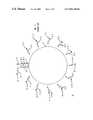
- FIG. 1depicts a well-known satellite-based navigational system referred to as Global Positioning System (GPS) 10 .
- Each satellite 12 - jorbiting earth at a known speed v j and being a known distance apart from the other satellites 12 - j.
- Each satellite 12 - jtransmits a GPS signal 11 - j which includes a carrier signal with a known frequency f modulated using a unique pseudo-random noise (PN-j) code and navigational data s(ND-) associated with the particular satellite 12 - j, wherein the PN-j code includes a unique sequence of PN chips and navigation data ND-j includes a satellite identifier, timing information and orbital data, such as elevation angle ⁇ j and azimuth angle ⁇ j .
- FIG. 2depicts a typical 20 ms frame of the GPS signal 11 - j which comprises twenty full sequences of a PN-j code in addition to a sequence of navigation data ND-j.
- GPS receiver 14replicates the carrier signals across a frequency spectrum f spec ranging from f+ ⁇ f min to f+ ⁇ f max until the frequency of the replicated carrier signal matches the frequency of the received GPS signal 11 - j, wherein ⁇ f min and ⁇ f max are a minimum and maximum change in frequency GPS signals 11 - j will undergo due to the Doppler effect as they travel from satellites 12 - j to GPS receiver 14 , i.e., ⁇ f min ⁇ f j ⁇ f max .
- a typical integration time for correlators 16 - kis 1 ms, which is generally sufficient for GPS receiver 14 to detect GPS signals 11 - j when antenna 15 has a clear view of the sky or a direct lie-of-sight to satellites 12 - j.
- 102.3 secondswould be required for one correlator 16 - k to search every possible combination of frequency and half-chip phase shifts for a PN-j code.
- Wireless assisted GPS (WAG) systemswere developed to facilitate detection of GPS signals 11 - j by GPS receivers configured with short or long integration times.
- the WAG systemfacilitates detection of GPS signals 11 - j by reducing the number of integrations to be performed by correlators searching for GPS signals 11 - j.
- the number of integrationsis reduced by narrowing the frequency range and code phase ranges to be searched.
- the WAG systemlimits the search for GPS signals 11 - j to a specific frequency or frequencies and to a range of code phases less than the code phase spectrum R j (spec).
- FIG. 3depicts a WAG system 20 comprising a WAG server 22 , a plurality of base stations 23 and at least one WAG client 24 .
- WAG server 22includes a GPS receiver 26 having an antenna 27 installed in a known stationary location with a clear view of the sky. GPS receiver 26 would typically have correlators configured with short integration times because antenna 27 has a clear view of the sky.
- WAG server 22being operable to communicate with base stations 23 either via a wired or wireless interface.
- Each base station 23has a known location and provides communication services to WAG clients located within a geographical area or cell 25 associated with the base station 23 , wherein each cell 25 is a known size and is divided into a plurality of sectors.
- WAG client 24includes a GPS receiver 28 and perhaps a mobile-telephone 27 , and is typically in motion and/or in an unknown location with or without a clear view of the sky.
- GPS receiver 28having correlators typically configured with long integration times.
- mobile-telephonefor purposes of this application, shall be construed to include, but is not limited to, any communication device.
- FIG. 4is a flowchart 300 illustrating the operation of WAG system 20 .
- WAG server 22detects a plurality of satellites 12 - j via their GPS signals 11 - j using its GPS receiver 26 .
- WAG server 22acquires the following information from each detected satellite 12 - j: the identity of satellite 12 - j and frequency f j , code phase, elevation angle ⁇ j and azimuth angle ⁇ j associated with the detected satellite 12 - j, wherein the elevation angle ⁇ j is defined as the angle between the line of sight from WAG server 22 or client 24 to a satellite 12 - j and a projection of the line of sight on the horizontal plane, and the azimuth angle ⁇ j is defined as the angle between the projection of the line of sight on the horizontal plane and a projection of the north direction on the horizontal plane. See FIG. 5 , which depicts an elevation angle ⁇ j and an azimuth angle ⁇ j corresponding to a satellite 12 - j and
- WAG server 22receives sector information from base station 23 currently in communication with or serving WAG client 24 , wherein the sector information indicates a sector WAG client 24 is currently located.
- WAG server 22makes an initial estimate of WAG client's position based on the known location of the serving base station, the cell size associated with the serving base station, and the sector in which WAG client 24 is currently located. In one embodiment, WAG server 22 initially estimates that WAG client 24 is located at a reference point within the sector, e.g., point at approximate center of sector. In another embodiment, WAG server 22 initially estimates WAG client 24 's position using well-known forward link triangulation techniques.
- WAG server 22uses the information acquired from the detected GPS signals 11 - j to predict a frequency f j (r) at the reference point and a code phase search range R j (sect) which includes all possible code phases for GPS signal 11 - j arriving anywhere within the sector where WAG client 24 is currently located.
- WAG server 22transmits a search message to the serving base station 23 , wherein the search message includes, for each detected satellite 12 - j, information re g the associated PN-j code, predicted frequency f j (r) and code phase search range R j (sect).
- serving base station 23transmits the search message to WAG client 24 which, in step 360 , begins a parallel search for the satellites 12 - j indicated in the search message.
- WAG client 24will use its correlators to simultaneously search for each of the GPS signals 11 - j at the predicted frequency f j (r) within the limitations of the code phase search range R j (sect) indicated in the search message.
- the number of integrationsis reduced to the predicted frequency f j (r) within the limitations of the code phase search range R j (sect).
- the search timeis still considered time consuming. Accordingly, there exists a need to facilitate detection of satellites 12 - j.
- the present inventionis a method and apparatus for facilitating detection of satellite signals using a dynamic integration technique.
- the present inventionuses a dynamic integration technique in which integration time periods of correlators are adjusted according to signal strength measurements of satellite signals received at GPS receivers. Specifically, integration time periods are inversely adjusted, either proportionally or non-proportionally, to received strengths of signals being searched. In one embodiment, when received signal strengths are above or equal to a threshold value, the integration time period is short, e.g., 1 millisecond. By contrast, when received signal strengths are below the threshold value, the integration time period is long, e.g., 1 second.
- the integration time periodis 1 second
- WAG clientis outdoors and the satellite signals are strong
- the integration time periodis 1 millisecond.
- the integration time periodsare dynamically and inversely adjusted according to received signal strengths of satellite signals, detection of satellite signals is facilitated without sacrificing accuracy of detection.
- one embodimentuses a sequential search technique during which satellites are searched for in a sequential manner based on knowledge acquired from detecting other satellite signals.
- FIG. 1depicts a well-known satellite-based navigational system referred to as Global Positioning System (GPS);
- GPSGlobal Positioning System
- FIG. 2depicts a typical 20 ms frame of a GPS signal
- FIG. 4depicts a flowchart illustrating the operation of the WAG system of FIG. 3 ;
- FIG. 5depicts an elevation angle ⁇ j and an azimuth angle ⁇ j corresponding to a satellite and a WAG server or WAG client;
- FIG. 6depicts a flowchart illustrating a sequential search technique and dynamic integration technique used in accordance with one embodiment of the present invention
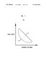
- FIG. 7depicts a chart illustrating two curves that may be used for determining integration time periods.
- FIG. 8depicts a sample power spectrum density of auto correlation for eight correlators spaced half a chip period apart.
- FIG. 6is a flowchart 600 illustrating a sequential search technique used in accordance with one embodiment of the present invention.
- WAG client 24receives a search message from its serving base station 23 or WAG server 22 .
- the search messageincludes, for each satellite 12 j detected by WAG server 22 , information regarding the associated PN-j code, predicted frequency f j (r) at a reference point within the sector/cell where WAG client 24 is currently located, code phase search range R j (sect) including all possible phase shifts for a GPS signal 11 - j transmitted by satellite 12 - j and arriving within the sector/cell where WAG client 24 is currently located, and orbital data including elevation angle ⁇ j and azimuth angle ⁇ j .
- WAG client 24selects a first satellite 12 - j indicated in the search message to search.
- WAG client 24uses one or more criteria in a set of first satellite selection criteria to select the first satellite 12 - j.
- the set of first satellite selection criteriaare as follows: (1) maximize utilization of correlators; (2) minimize search time; and (3) maximize the amount of information regarding location of WAG client 24 (or GPS receiver 14 or antenna 15 ).
- the first criteria of maximizing utilization of correlatorsinvolves using as many of the available correlators to simultaneously search for a satellite 12 - j.
- the second criteria of minimizing search timeinvolves reducing the number of integrations to be performed by each correlator, e.g., each correlator performs one integration. Reducing the number of integrations to be performed by each correlator essentially means selecting a satellite 12 - j having the smallest associated code phase search range R j indicated in the search message.
- the third criteria of maximizing the amount of information regarding the location of WAG client 24involves selecting a satellite 12 - j that, when detected, will indicate an area in the sector where WAG client 24 is located. For example, a satellite 12 - j with a small elevation angle a j , when detected, will indicate a narrow strait in the sector where WAG client is located, whereas a satellite 12 - j with a large elevation angle ⁇ j will indicate a wider strait in the sector where WAG client is located.
- WAG client 24determines an integration time period for correlators 16 - k at which to search for the first satellite 12 - j, wherein the integration time period will depend upon the received signal strength measurements at WAG client 24 (or server 22 ) of signals 11 - j transmitted by the first or any satellite 12 - j.
- WAG client 24measures the signal strength of signals transmitted on or about frequency f+ ⁇ f j as indicated in the search message for the first satellite 12 - j. In another embodiment, WAG client measures the signal strength of signals transmitted on frequency f.
- the integration time periodsvary inversely, either proportionally or non-proportionally, to the signal strength measurements of signals 11 - j. For example, if the received signal strength measurements of signals 11 - j increase, the integration time periods for correlators 16 - k decrease. In one embodiment, if the received signal strength measurements of signals 11 - j at WAG client 24 is below a threshold value, the integration time period is maximized, and vice-versa.
- the integration time period of correlators 16 - kis set to 1 second, whereas if WAG client 24 measures the strength of signals 11 - j to be above or equal to the threshold value, the integration time period of correlators 16 - k is set to 1 millisecond.
- the integration time periodis set to shortest duration; if the signal strength is above the lowest threshold value but below the highest threshold value, the integration time period is set to second shortest or second longest duration; and if the signal strength is above the highest threshold value, the integration time period is set to longest duration.
- the integration time periodsare determined according to the received signal strengths and a curve or mathematical equation. See FIG. 7 , which depicts a chart 70 illustrating two possible relationships between received signal strength measurements and integration time periods.
- relative signal strengthsare used to determine whether GPS receiver 14 is indoors or outdoors which, in turn, determines the integration time periods. For example, suppose GPS receiver 14 has eight correlators which are spaced half a chip period apart. Each correlators samples or measures signal strengths (for a particular signal 11 - j or PN-j sequence) every millisecond over a twenty millisecond time period, i.e., each correlator perform twenty samples. For each set of samples collected by a correlator, a Fourier transform is applied to obtain a power spectrum density of auto correlation for each correlator. FIG. 8 depicts a three dimensional chart 80 illustrating a possible power spectrum density of auto correlation for eight correlators spaced half a chip period apart.
- a maximum power spectrum density value over all the correlators(P max ) is divided over an average power spectrum density value (P avg ) over all the correlators to obtain a power spectrum density ratio (P ratio ).
- P ratiopower spectrum density ratio
- the power spectrum density ratio P ratiois then compared to a threshold value to determined integration time periods.
- a small P ratiowould indicate that GPS receiver 14 is indoors, whereas a large or larger P ratio would indicate that GPS receiver 14 is outdoors.
- P maxshould not be much greater than P avg and P ratio should be a small value (e.g., a value greater than but close to one).
- P maxshould be much greater than P avg and P ratio should be a large or larger value (e.g., a value greater than and not close to one).
- WAG client 24searches for the first satellite 12 - j for the determined integration time period using the frequency f j (r) and code phase search range R j (sect) indicated in the search message for the first satellite 12 - j.
- WAG client 24predicts a first area in which WAG client 24 may be located using information extracted from a GPS signal 11 - j transmitted by the first satellite 12 - j, as is well-known in the art.
- the first predicted areatypically being a strait or small area within the sector where WAG client 24 is currently located. Such calculation is later used to narrow down the code phase search range R j of subsequent satellite searches.
- WAG client 24uses the search message to pick a second satellite 12 - j to search.
- WAG client 24uses one or more criteria in a set of second satellite selection criteria to select the second satellite 12 - j.
- the set of second satellite selection criteriaare as follows: (1) maximize utilization of correlators; (2) minimize search time; and (3) maximize the amount of additional information regarding location of WAG client 24 (or GPS receiver 14 or antenna 15 ) when used in conjunction with the results of the first search.
- the first and second criteriabeing identical to the first and second criteria of step 610 .
- the third criteriainvolves selecting a second satellite 12 - j that will result in an area which intersects least, but nevertheless intersects, with the first predicted area.
- the second satellite 12 - j selectedis a satellite 12 - j that forms an angle of approximately 90° with the first satellite and WAG server 22 or WAG client 24 , wherein WAG server 22 or WAG client 24 is the vertex.
- the angle between the fist and second satellites and WAG server 22 or client 24can be determined using a difference between azimuth angles associated with the fist and second satellites.
- WAG client 24redefines or narrows down the code phase search range R j (sect) indicated in the search message for the second satellite 12 - j based on the first predicted area.
- the redefined or narrowed down code phase search range R j (sect)is hereinafter referred to as a “predicted code phase search range R j (pred).”
- the predicted code phase search range R j (pred) for the second satelliteincludes all possible phase shifts for GPS signals 11 - j transmitted by the second satellite and arriving in the first predicted area.
- the corresponding predicted code phase search range R j (pred)will be narrower than the corresponding code phase search range R j (sect) originally indicated in the search message for the second satellite.
- WAG client 24determines an integration time period for correlators 16 - k at which to search for the second satellite 12 - j based on received signal strength measurements. As in step 620 , WAG client 24 can either measure the signal strength of signals transmitted on or about frequency f+ ⁇ f j as indicated in the search message for the second satellite 12 - j or on frequency f. In step 650 , WAG client 24 searches for the second satellite 12 - j, for the integration time period determined in step 638 , using the frequency f j (r) indicated in the search message and the predicted code phase search range R j (pred) for the second satellite 12 - j. In another embodiment, the integration time period may be re-determined prior to step 650 .
- WAG client 24predicts a second area in which WAG client 24 may be located using information extracted from a GPS signal 11 - j transmitted by the second satellite 12 - j. Like the first predicted area, the second predicted area is typically a strait or small area within the sector in which WAG client 24 is currently located.
- step 660WAG client 24 uses the intersected area and the code phase search range R j (sect) indicated in the search message to predict code phase search range R j (pred) for the remaining satellites 12 - j indicated in the search message, thereby facilitating detection of the remaining satellites 12 - j.
- Such predicted code phase search ranges R j (pred)include code phases for GPS signals 11 - j transmitted by the remaining satellites indicated in the search message and arriving anywhere within the intersected area.
- WAG client 24determines integration time periods for correlators 16 - k at which to search for the remaining satellite 12 - j (i.e., all other satellites 12 - j indicated in the search message other than the first and second satellites) based on received signal strength measurements. As in step 620 , WAG client 24 can either measure the sign strength of signals transmitted on or about frequency f+ ⁇ f j as indicated in the search message for the remaining satellites 12 - j or on frequency f. In step 670 , WAG client 24 searches for the remaining satellites 12 - j, for the integration time period determined in step 665 , within the confines of the predicted code phase search ranges R j (pred) for the remaining satellites 12 - j.
- WAG client 24uses its correlators to perform parallel searches for two or more remaining satellites 12 - j. Upon detecting the remaining satellites 12 - j, in step 680 , WAG client 24 calculates its location using the navigation data ND-j extracted from GPS signals 11 - j transmitted by at least three satellites 11 - j, as is well-known in the art.
- the present inventionis described herein with reference to certain embodiments, including an embodiment in which the first, second and all or some of the remaining satellites are searched sequentially.
- the sequential search of the present inventionmay involve GPS receiver 28 searching in parallel for the first and second satellites, and then searching in parallel for all or some of the remaining satellites.
- the present inventionis also applicable to non-GPS satellite-based or non-satellite-based navigation system. Accordingly, the present invention should not be limited to the embodiments disclosed herein.
Landscapes
- Engineering & Computer Science (AREA)
- Radar, Positioning & Navigation (AREA)
- Remote Sensing (AREA)
- Computer Networks & Wireless Communication (AREA)
- Physics & Mathematics (AREA)
- General Physics & Mathematics (AREA)
- Signal Processing (AREA)
- Electromagnetism (AREA)
- Position Fixing By Use Of Radio Waves (AREA)
- Radio Relay Systems (AREA)
Abstract
Description
Claims (13)
Priority Applications (8)
| Application Number | Priority Date | Filing Date | Title |
|---|---|---|---|
| US09/391,123US6965760B1 (en) | 1999-09-07 | 1999-09-07 | Satellite-based location system employing dynamic integration techniques |
| BR0003858-0ABR0003858A (en) | 1999-09-07 | 2000-08-29 | Satellite-based location system employing dynamic integration techniques |
| EP00307371AEP1083440A3 (en) | 1999-09-07 | 2000-08-29 | A satellite-based location system employing dynamic integration techniques |
| CA002317143ACA2317143A1 (en) | 1999-09-07 | 2000-08-30 | A satellite-based location system employing dynamic integration techniques |
| AU55061/00AAU5506100A (en) | 1999-09-07 | 2000-08-31 | A satellite-based location system employing dynamic integration techniques |
| JP2000268040AJP2001124842A (en) | 1999-09-07 | 2000-09-05 | Method for detecting plurality of signals |
| CN00126841ACN1287273A (en) | 1999-09-07 | 2000-09-06 | Satellite primary fixer system using dynamic integration technology |
| KR1020000053115AKR20010030317A (en) | 1999-09-07 | 2000-09-07 | A satellite-based location system employing dynamic integration techniques |
Applications Claiming Priority (1)
| Application Number | Priority Date | Filing Date | Title |
|---|---|---|---|
| US09/391,123US6965760B1 (en) | 1999-09-07 | 1999-09-07 | Satellite-based location system employing dynamic integration techniques |
Publications (1)
| Publication Number | Publication Date |
|---|---|
| US6965760B1true US6965760B1 (en) | 2005-11-15 |
Family
ID=23545347
Family Applications (1)
| Application Number | Title | Priority Date | Filing Date |
|---|---|---|---|
| US09/391,123Expired - LifetimeUS6965760B1 (en) | 1999-09-07 | 1999-09-07 | Satellite-based location system employing dynamic integration techniques |
Country Status (8)
| Country | Link |
|---|---|
| US (1) | US6965760B1 (en) |
| EP (1) | EP1083440A3 (en) |
| JP (1) | JP2001124842A (en) |
| KR (1) | KR20010030317A (en) |
| CN (1) | CN1287273A (en) |
| AU (1) | AU5506100A (en) |
| BR (1) | BR0003858A (en) |
| CA (1) | CA2317143A1 (en) |
Cited By (19)
| Publication number | Priority date | Publication date | Assignee | Title |
|---|---|---|---|---|
| US7283091B1 (en)* | 2005-08-08 | 2007-10-16 | Trimble Navigation Limited | Radio positioning system for providing position and time for assisting GPS signal acquisition in mobile unit |
| US7295156B2 (en)* | 2005-08-08 | 2007-11-13 | Trimble Navigation Limited | Cellphone GPS positioning system |
| US20070300045A1 (en)* | 2006-06-21 | 2007-12-27 | Dominic Gerard Farmer | Device and methods for coping with inefficiency from general purpose processors in implementing algorithms |
| US20080084336A1 (en)* | 2006-10-10 | 2008-04-10 | Chi-Shin Wang | Method of mixed data assisted and non data assisted navigation signal acquisition, tracking and reacquisition |
| US20080150797A1 (en)* | 2006-12-22 | 2008-06-26 | Zhike Jia | Navigational signal tracking in low power mode |
| US20090010239A1 (en)* | 2007-07-05 | 2009-01-08 | Mediatek Inc. | Control of cdma signal integration |
| US7557751B2 (en) | 2006-09-07 | 2009-07-07 | Seiko Epson Corporation | Terminal device, method of controlling terminal device, and recording medium |
| US20090189809A1 (en)* | 2008-01-29 | 2009-07-30 | Seiko Epson Corporation | Satellite Signal Reception Device And Control Method For A Satellite Signal Reception Device |
| US20090224976A1 (en)* | 2003-07-03 | 2009-09-10 | Qualcomm Incorporated | Gps receiver with fast acquisition time |
| US20090295632A1 (en)* | 2008-05-30 | 2009-12-03 | Qualcomm Incorporated | Methods and Apparatuses for Processing Satellite Positioning System Signals |
| US20100178930A1 (en)* | 2009-01-13 | 2010-07-15 | Mediatek Inc. | Positioning method and navigation device |
| US7924220B1 (en) | 2008-11-24 | 2011-04-12 | Sirf Technology Holdings, Inc. | Method and apparatus for weak data frame sync in a positioning system |
| US20110156952A1 (en)* | 2009-12-31 | 2011-06-30 | Polaris Wireless, Inc. | Positioning System and Positioning Method |
| US20110156951A1 (en)* | 2009-12-31 | 2011-06-30 | Polaris Wireless, Inc. | Positioning System and Positioning Method |
| US20110156950A1 (en)* | 2009-12-31 | 2011-06-30 | Polaris Wireless, Inc. | Positioning System and Positioning Method |
| US8954267B2 (en)* | 2013-02-21 | 2015-02-10 | Qualcomm Incorporated | Mobile device positioning |
| US9185675B2 (en) | 2013-11-18 | 2015-11-10 | Qualcomm Incorporated | Method and apparatus for classifying a mobile device location |
| US20220043166A1 (en)* | 2019-03-01 | 2022-02-10 | Google Llc | Determining Velocity Using a Reflected Positioning Signal |
| CN114301554A (en)* | 2021-12-31 | 2022-04-08 | 浙江时空道宇科技有限公司 | A satellite test system |
Families Citing this family (14)
| Publication number | Priority date | Publication date | Assignee | Title |
|---|---|---|---|---|
| US6542116B1 (en)* | 2001-06-22 | 2003-04-01 | Enuvis, Inc. | Determining the spatio-temporal and kinematic parameters of a signal receiver and its clock by information fusion |
| GB0122228D0 (en)* | 2001-09-13 | 2001-11-07 | Koninl Philips Electronics Nv | GPS receiver and related method |
| US7729412B2 (en) | 2001-10-29 | 2010-06-01 | Qualcomm Incorporated | Parameter estimator with dynamically variable integration time |
| US7558534B2 (en) | 2001-11-02 | 2009-07-07 | Qualcomm Incorporated | Reliability metrics for parameter estimates which account for cumulative error |
| TWI231105B (en) | 2003-11-06 | 2005-04-11 | Prolific Technology Inc | Global positioning satellite and correlating circuit thereof |
| JP3837419B2 (en)* | 2004-05-10 | 2006-10-25 | マゼランシステムズジャパン株式会社 | Satellite positioning method and satellite positioning system |
| US7570208B2 (en)* | 2005-12-29 | 2009-08-04 | Sirf Technology, Inc. | Unassisted indoor GPS receiver |
| JP4857850B2 (en)* | 2006-03-28 | 2012-01-18 | セイコーエプソン株式会社 | POSITIONING DEVICE AND POSITIONING DEVICE CONTROL METHOD |
| US8149897B2 (en)* | 2006-05-26 | 2012-04-03 | Global Locate, Inc. | Method and apparatus for performing signal correlation for signals received from satellites in multiple satellite systems |
| US7898474B2 (en) | 2006-07-20 | 2011-03-01 | Seiko Epson Corporation | Positioning device, method of controlling positioning device, and recording medium having program for controlling positioning device recorded thereon |
| US8026847B2 (en)* | 2006-09-14 | 2011-09-27 | Qualcomm Incorporated | System and/or method for acquisition of GNSS signals |
| JP4650467B2 (en)* | 2007-09-26 | 2011-03-16 | セイコーエプソン株式会社 | Time correction device and timing device with time correction device |
| JP5186874B2 (en)* | 2007-10-10 | 2013-04-24 | セイコーエプソン株式会社 | POSITIONING METHOD, PROGRAM, POSITIONING DEVICE, AND ELECTRONIC DEVICE |
| KR101413876B1 (en)* | 2010-11-15 | 2014-06-30 | 한국전자통신연구원 | Apparatus and method for non-coherent integration in global navigation satellite system receiver |
Citations (9)
| Publication number | Priority date | Publication date | Assignee | Title |
|---|---|---|---|---|
| WO1995014937A1 (en) | 1993-11-29 | 1995-06-01 | Novatel Communications Ltd. | Pseudorandom noise ranging receiver which compensates for multipath distortion by making use of multiple correlator time delay spacing |
| US5576715A (en)* | 1994-03-07 | 1996-11-19 | Leica, Inc. | Method and apparatus for digital processing in a global positioning system receiver |
| WO1998002759A1 (en) | 1996-07-12 | 1998-01-22 | General Electric Company | Gps receiver with efficient signal acquisition |
| WO1998025157A2 (en) | 1996-12-04 | 1998-06-11 | Snaptrack, Inc. | An improved gps receiver utilizing a communication link |
| US5805200A (en)* | 1982-03-01 | 1998-09-08 | Western Atlas International, Inc. | System for determining position from pseudorandomly modulated radio signals |
| JPH11186987A (en) | 1997-12-22 | 1999-07-09 | Matsushita Electric Ind Co Ltd | CDMA receiver phase tracking device |
| US6075987A (en)* | 1998-02-27 | 2000-06-13 | Ericsson Inc. | Stand alone global positioning system (GPS) and method with high sensitivity |
| US6298083B1 (en)* | 1998-03-16 | 2001-10-02 | Trimble Navigation Limited | Power savings technique for a positioning system receiver |
| US6313789B1 (en)* | 1998-06-10 | 2001-11-06 | Topcon Positioning Systems, Inc. | Joint tracking of the carrier phases of the signals received from different satellites |
- 1999
- 1999-09-07USUS09/391,123patent/US6965760B1/ennot_activeExpired - Lifetime
- 2000
- 2000-08-29EPEP00307371Apatent/EP1083440A3/ennot_activeWithdrawn
- 2000-08-29BRBR0003858-0Apatent/BR0003858A/ennot_activeApplication Discontinuation
- 2000-08-30CACA002317143Apatent/CA2317143A1/ennot_activeAbandoned
- 2000-08-31AUAU55061/00Apatent/AU5506100A/ennot_activeAbandoned
- 2000-09-05JPJP2000268040Apatent/JP2001124842A/enactivePending
- 2000-09-06CNCN00126841Apatent/CN1287273A/enactivePending
- 2000-09-07KRKR1020000053115Apatent/KR20010030317A/ennot_activeCeased
Patent Citations (10)
| Publication number | Priority date | Publication date | Assignee | Title |
|---|---|---|---|---|
| US5805200A (en)* | 1982-03-01 | 1998-09-08 | Western Atlas International, Inc. | System for determining position from pseudorandomly modulated radio signals |
| WO1995014937A1 (en) | 1993-11-29 | 1995-06-01 | Novatel Communications Ltd. | Pseudorandom noise ranging receiver which compensates for multipath distortion by making use of multiple correlator time delay spacing |
| US5576715A (en)* | 1994-03-07 | 1996-11-19 | Leica, Inc. | Method and apparatus for digital processing in a global positioning system receiver |
| WO1998002759A1 (en) | 1996-07-12 | 1998-01-22 | General Electric Company | Gps receiver with efficient signal acquisition |
| WO1998025157A2 (en) | 1996-12-04 | 1998-06-11 | Snaptrack, Inc. | An improved gps receiver utilizing a communication link |
| JPH11186987A (en) | 1997-12-22 | 1999-07-09 | Matsushita Electric Ind Co Ltd | CDMA receiver phase tracking device |
| US6490265B1 (en) | 1997-12-22 | 2002-12-03 | Matsushita Electric Industrial Co., Ltd. | CDMA receiver phase tracking system |
| US6075987A (en)* | 1998-02-27 | 2000-06-13 | Ericsson Inc. | Stand alone global positioning system (GPS) and method with high sensitivity |
| US6298083B1 (en)* | 1998-03-16 | 2001-10-02 | Trimble Navigation Limited | Power savings technique for a positioning system receiver |
| US6313789B1 (en)* | 1998-06-10 | 2001-11-06 | Topcon Positioning Systems, Inc. | Joint tracking of the carrier phases of the signals received from different satellites |
Non-Patent Citations (1)
| Title |
|---|
| European Search Report. |
Cited By (40)
| Publication number | Priority date | Publication date | Assignee | Title |
|---|---|---|---|---|
| US20090224976A1 (en)* | 2003-07-03 | 2009-09-10 | Qualcomm Incorporated | Gps receiver with fast acquisition time |
| US20070252758A1 (en)* | 2005-08-08 | 2007-11-01 | Loomis Peter V W | Radio positioning system for providing position and time for assisting gps signal acquisition in mobile unit |
| US7295156B2 (en)* | 2005-08-08 | 2007-11-13 | Trimble Navigation Limited | Cellphone GPS positioning system |
| US7283091B1 (en)* | 2005-08-08 | 2007-10-16 | Trimble Navigation Limited | Radio positioning system for providing position and time for assisting GPS signal acquisition in mobile unit |
| EP2466326A3 (en)* | 2006-06-21 | 2012-12-12 | Qualcomm Incorporated | Device and methods for coping with inefficiency from general purpose processors in implementing algorithms |
| US20070300045A1 (en)* | 2006-06-21 | 2007-12-27 | Dominic Gerard Farmer | Device and methods for coping with inefficiency from general purpose processors in implementing algorithms |
| RU2418303C2 (en)* | 2006-06-21 | 2011-05-10 | Квэлкомм Инкорпорейтед | Methods of compensating for inefficiency of universal processes when realising algorithms and apparatus for realising said methods |
| US7689810B2 (en)* | 2006-06-21 | 2010-03-30 | Qualcomm Incorporated | Processor generating control signals including detection duration for satellite positioning system ranging signal detection circuit |
| US7557751B2 (en) | 2006-09-07 | 2009-07-07 | Seiko Epson Corporation | Terminal device, method of controlling terminal device, and recording medium |
| US20090237301A1 (en)* | 2006-09-07 | 2009-09-24 | Seiko Epson Corporation | Terminal device, method of controlling terminal device, and recording medium |
| US7719468B2 (en) | 2006-09-07 | 2010-05-18 | Seiko Epson Corporation | Terminal device, method of controlling terminal device, and recording medium |
| US7859456B2 (en) | 2006-10-10 | 2010-12-28 | Sirf Technology Holdings, Inc. | Method of mixed data assisted and non data assisted navigation signal acquisition, tracking and reacquisition |
| DE112007002448B4 (en) | 2006-10-10 | 2022-10-27 | Csr Technology Holdings Inc. (N. D. Ges. D. Staates Delaware) | Mixed data-based and non-data-based navigation signal acquisition, tracking and reacquisition method |
| US20080084336A1 (en)* | 2006-10-10 | 2008-04-10 | Chi-Shin Wang | Method of mixed data assisted and non data assisted navigation signal acquisition, tracking and reacquisition |
| DE112007002448T5 (en) | 2006-10-10 | 2009-09-10 | Sirf Technology, INC., Redwood City | Method of mixed data-aided and non-data-assisted navigation signal acquisition, tracking, and recapture |
| US20080150797A1 (en)* | 2006-12-22 | 2008-06-26 | Zhike Jia | Navigational signal tracking in low power mode |
| US7847726B2 (en) | 2006-12-22 | 2010-12-07 | Sirf Technology Holdings, Inc. | Navigational signal tracking in low power mode |
| US7903600B2 (en)* | 2007-07-05 | 2011-03-08 | Mediatek Inc. | Control of CDMA signal integration |
| US20090010239A1 (en)* | 2007-07-05 | 2009-01-08 | Mediatek Inc. | Control of cdma signal integration |
| US8666344B2 (en) | 2008-01-29 | 2014-03-04 | Seiko Epson Corporation | Satellite signal reception device and control method for a satellite signal reception device |
| US20090189809A1 (en)* | 2008-01-29 | 2009-07-30 | Seiko Epson Corporation | Satellite Signal Reception Device And Control Method For A Satellite Signal Reception Device |
| US20090295632A1 (en)* | 2008-05-30 | 2009-12-03 | Qualcomm Incorporated | Methods and Apparatuses for Processing Satellite Positioning System Signals |
| US8081922B2 (en)* | 2008-05-30 | 2011-12-20 | Qualcomm Incorporated | Methods and apparatuses for processing satellite positioning system signals |
| US7924220B1 (en) | 2008-11-24 | 2011-04-12 | Sirf Technology Holdings, Inc. | Method and apparatus for weak data frame sync in a positioning system |
| US20110193742A1 (en)* | 2008-11-24 | 2011-08-11 | Sirf Technology Holdings, Inc. | Method and Apparatus for Weak Data Frame Sync in a Positioning System |
| US8134501B2 (en) | 2008-11-24 | 2012-03-13 | CSR Technology Holdings Inc. | Method and apparatus for weak data frame sync in a positioning system |
| US20100178930A1 (en)* | 2009-01-13 | 2010-07-15 | Mediatek Inc. | Positioning method and navigation device |
| US8339313B2 (en) | 2009-01-13 | 2012-12-25 | Mediatek Inc. | Positioning method and navigation device |
| US8106818B2 (en)* | 2009-12-31 | 2012-01-31 | Polaris Wireless, Inc. | Positioning system and positioning method |
| US8106817B2 (en)* | 2009-12-31 | 2012-01-31 | Polaris Wireless, Inc. | Positioning system and positioning method |
| US8013785B2 (en)* | 2009-12-31 | 2011-09-06 | Ntt Docomo, Inc. | Positioning system and positioning method |
| US20110156950A1 (en)* | 2009-12-31 | 2011-06-30 | Polaris Wireless, Inc. | Positioning System and Positioning Method |
| US20110156951A1 (en)* | 2009-12-31 | 2011-06-30 | Polaris Wireless, Inc. | Positioning System and Positioning Method |
| US20110156952A1 (en)* | 2009-12-31 | 2011-06-30 | Polaris Wireless, Inc. | Positioning System and Positioning Method |
| US8954267B2 (en)* | 2013-02-21 | 2015-02-10 | Qualcomm Incorporated | Mobile device positioning |
| US9185675B2 (en) | 2013-11-18 | 2015-11-10 | Qualcomm Incorporated | Method and apparatus for classifying a mobile device location |
| US20220043166A1 (en)* | 2019-03-01 | 2022-02-10 | Google Llc | Determining Velocity Using a Reflected Positioning Signal |
| US12140686B2 (en)* | 2019-03-01 | 2024-11-12 | Google Llc | Determining velocity using a reflected positioning signal |
| CN114301554A (en)* | 2021-12-31 | 2022-04-08 | 浙江时空道宇科技有限公司 | A satellite test system |
| CN114301554B (en)* | 2021-12-31 | 2024-06-07 | 浙江时空道宇科技有限公司 | A satellite test system |
Also Published As
| Publication number | Publication date |
|---|---|
| CA2317143A1 (en) | 2001-03-07 |
| CN1287273A (en) | 2001-03-14 |
| JP2001124842A (en) | 2001-05-11 |
| EP1083440A3 (en) | 2003-04-02 |
| AU5506100A (en) | 2001-03-08 |
| KR20010030317A (en) | 2001-04-16 |
| BR0003858A (en) | 2001-04-03 |
| EP1083440A2 (en) | 2001-03-14 |
Similar Documents
| Publication | Publication Date | Title |
|---|---|---|
| US6965760B1 (en) | Satellite-based location system employing dynamic integration techniques | |
| US6459405B1 (en) | Satellite-based location system employing knowledge-based sequential signal search strategy | |
| US6922546B1 (en) | GPS signal acquisition based on frequency-domain and time-domain processing | |
| US6661371B2 (en) | Oscillator frequency correction in GPS signal acquisition | |
| US6121923A (en) | Fixed site and satellite data-aided GPS signal acquisition method and system | |
| US6295023B1 (en) | Methods, mobile stations and systems for acquiring global positioning system timing information | |
| US6570533B2 (en) | Method for determining the phase of information, and an electronic device | |
| US8063819B2 (en) | Positioning device, positioning control method, positioning control program, and computer-readable recording medium having positioning control program recorded thereon | |
| WO2000049695A1 (en) | Gps signal acquisition method and system | |
| JP5015788B2 (en) | Method and apparatus for increasing coherent integration length while receiving positioning signal | |
| KR20010033226A (en) | Method for determining the location of a gps receiver using an estimated reference time | |
| US20050285781A1 (en) | GPS receiver and method for detecting a jammer signal using fast fourier transform | |
| US7151793B2 (en) | Method for synchronizing a receiver, a positioning system, a receiver and an electronic device | |
| CN102016622A (en) | Methods and apparatuses for processing satellite positioning system signals | |
| US7142878B1 (en) | Method of timing calibration | |
| KR20020092718A (en) | GPS Receiver and Method for Determining Position of a Wireless Terminal | |
| US8238411B2 (en) | Acquisition of a code modulated signal | |
| EP1763682A1 (en) | Assisted satellite-based positioning | |
| EP1229341B1 (en) | A method for defining the error of reference time and an electronic device | |
| JP2007263660A (en) | POSITIONING DEVICE, POSITIONING DEVICE CONTROL METHOD, AND POSITIONING DEVICE CONTROL PROGRAM | |
| KR100900163B1 (en) | Recognition of code modulated signals |
Legal Events
| Date | Code | Title | Description |
|---|---|---|---|
| AS | Assignment | Owner name:LUCENT TECHNOLOGIES INC., NEW JERSEY Free format text:ASSIGNMENT OF ASSIGNORS INTEREST;ASSIGNORS:CHEN, BYRON HUA;CHIANG, TUNG CHING;DA, REN;AND OTHERS;REEL/FRAME:010229/0779 Effective date:19990902 | |
| FEPP | Fee payment procedure | Free format text:PAYOR NUMBER ASSIGNED (ORIGINAL EVENT CODE: ASPN); ENTITY STATUS OF PATENT OWNER: LARGE ENTITY | |
| STCF | Information on status: patent grant | Free format text:PATENTED CASE | |
| FEPP | Fee payment procedure | Free format text:PAYER NUMBER DE-ASSIGNED (ORIGINAL EVENT CODE: RMPN); ENTITY STATUS OF PATENT OWNER: LARGE ENTITY Free format text:PAYOR NUMBER ASSIGNED (ORIGINAL EVENT CODE: ASPN); ENTITY STATUS OF PATENT OWNER: LARGE ENTITY | |
| FPAY | Fee payment | Year of fee payment:4 | |
| AS | Assignment | Owner name:CREDIT SUISSE AG, NEW YORK Free format text:SECURITY INTEREST;ASSIGNOR:ALCATEL-LUCENT USA INC.;REEL/FRAME:030510/0627 Effective date:20130130 | |
| FPAY | Fee payment | Year of fee payment:8 | |
| AS | Assignment | Owner name:ALCATEL-LUCENT USA INC., NEW JERSEY Free format text:RELEASE BY SECURED PARTY;ASSIGNOR:CREDIT SUISSE AG;REEL/FRAME:033950/0001 Effective date:20140819 | |
| FPAY | Fee payment | Year of fee payment:12 |