US6965501B1 - Integrated lead suspension for high density drive - Google Patents
Integrated lead suspension for high density driveDownload PDFInfo
- Publication number
- US6965501B1 US6965501B1US09/676,216US67621600AUS6965501B1US 6965501 B1US6965501 B1US 6965501B1US 67621600 AUS67621600 AUS 67621600AUS 6965501 B1US6965501 B1US 6965501B1
- Authority
- US
- United States
- Prior art keywords
- load beam
- slider
- section
- suspension assembly
- limiter
- Prior art date
- Legal status (The legal status is an assumption and is not a legal conclusion. Google has not performed a legal analysis and makes no representation as to the accuracy of the status listed.)
- Expired - Lifetime, expires
Links
- 239000000725suspensionSubstances0.000titleclaimsabstractdescription97
- 238000009413insulationMethods0.000claimsabstractdescription23
- 238000005452bendingMethods0.000claimsabstractdescription13
- 238000000926separation methodMethods0.000claimsabstractdescription11
- 229910000679solderInorganic materials0.000claimsabstractdescription10
- 238000003780insertionMethods0.000claimsabstractdescription7
- 230000037431insertionEffects0.000claimsabstractdescription7
- 238000003860storageMethods0.000claimsdescription18
- 238000012545processingMethods0.000claimsdescription2
- 238000000034methodMethods0.000abstractdescription10
- 239000004033plasticSubstances0.000abstractdescription7
- 230000035939shockEffects0.000abstractdescription7
- 230000008569processEffects0.000abstractdescription6
- 229910001220stainless steelInorganic materials0.000description15
- 239000010935stainless steelSubstances0.000description15
- 239000004642PolyimideSubstances0.000description9
- 230000000712assemblyEffects0.000description9
- 238000000429assemblyMethods0.000description9
- 229920001721polyimidePolymers0.000description9
- RYGMFSIKBFXOCR-UHFFFAOYSA-NCopperChemical compound[Cu]RYGMFSIKBFXOCR-UHFFFAOYSA-N0.000description7
- 229910052802copperInorganic materials0.000description7
- 239000010949copperSubstances0.000description7
- 229910000831SteelInorganic materials0.000description6
- 239000010959steelSubstances0.000description6
- 238000013461designMethods0.000description4
- 238000003466weldingMethods0.000description4
- 238000005299abrasionMethods0.000description3
- 230000005284excitationEffects0.000description3
- 238000004519manufacturing processMethods0.000description3
- 230000036316preloadEffects0.000description3
- 239000004020conductorSubstances0.000description2
- MPTQRFCYZCXJFQ-UHFFFAOYSA-Lcopper(II) chloride dihydrateChemical compoundO.O.[Cl-].[Cl-].[Cu+2]MPTQRFCYZCXJFQ-UHFFFAOYSA-L0.000description2
- 239000000428dustSubstances0.000description2
- 239000002184metalSubstances0.000description2
- 229910052751metalInorganic materials0.000description2
- 230000009471actionEffects0.000description1
- 238000013459approachMethods0.000description1
- 230000000295complement effectEffects0.000description1
- 230000002950deficientEffects0.000description1
- 230000003993interactionEffects0.000description1
- 239000000463materialSubstances0.000description1
- 230000007246mechanismEffects0.000description1
- 239000002245particleSubstances0.000description1
- 230000004044responseEffects0.000description1
- 239000010409thin filmSubstances0.000description1
Images


Classifications
- G—PHYSICS
- G11—INFORMATION STORAGE
- G11B—INFORMATION STORAGE BASED ON RELATIVE MOVEMENT BETWEEN RECORD CARRIER AND TRANSDUCER
- G11B5/00—Recording by magnetisation or demagnetisation of a record carrier; Reproducing by magnetic means; Record carriers therefor
- G11B5/48—Disposition or mounting of heads or head supports relative to record carriers ; arrangements of heads, e.g. for scanning the record carrier to increase the relative speed
- G11B5/4806—Disposition or mounting of heads or head supports relative to record carriers ; arrangements of heads, e.g. for scanning the record carrier to increase the relative speed specially adapted for disk drive assemblies, e.g. assembly prior to operation, hard or flexible disk drives
- G11B5/486—Disposition or mounting of heads or head supports relative to record carriers ; arrangements of heads, e.g. for scanning the record carrier to increase the relative speed specially adapted for disk drive assemblies, e.g. assembly prior to operation, hard or flexible disk drives with provision for mounting or arranging electrical conducting means or circuits on or along the arm assembly
- G—PHYSICS
- G11—INFORMATION STORAGE
- G11B—INFORMATION STORAGE BASED ON RELATIVE MOVEMENT BETWEEN RECORD CARRIER AND TRANSDUCER
- G11B5/00—Recording by magnetisation or demagnetisation of a record carrier; Reproducing by magnetic means; Record carriers therefor
- G11B5/48—Disposition or mounting of heads or head supports relative to record carriers ; arrangements of heads, e.g. for scanning the record carrier to increase the relative speed
- G11B5/4806—Disposition or mounting of heads or head supports relative to record carriers ; arrangements of heads, e.g. for scanning the record carrier to increase the relative speed specially adapted for disk drive assemblies, e.g. assembly prior to operation, hard or flexible disk drives
- G11B5/484—Integrated arm assemblies, e.g. formed by material deposition or by etching from single piece of metal or by lamination of materials forming a single arm/suspension/head unit
- Y—GENERAL TAGGING OF NEW TECHNOLOGICAL DEVELOPMENTS; GENERAL TAGGING OF CROSS-SECTIONAL TECHNOLOGIES SPANNING OVER SEVERAL SECTIONS OF THE IPC; TECHNICAL SUBJECTS COVERED BY FORMER USPC CROSS-REFERENCE ART COLLECTIONS [XRACs] AND DIGESTS
- Y10—TECHNICAL SUBJECTS COVERED BY FORMER USPC
- Y10T—TECHNICAL SUBJECTS COVERED BY FORMER US CLASSIFICATION
- Y10T29/00—Metal working
- Y10T29/49—Method of mechanical manufacture
- Y10T29/49002—Electrical device making
- Y10T29/4902—Electromagnet, transformer or inductor
- Y10T29/49021—Magnetic recording reproducing transducer [e.g., tape head, core, etc.]
- Y10T29/49025—Making disc drive
- Y—GENERAL TAGGING OF NEW TECHNOLOGICAL DEVELOPMENTS; GENERAL TAGGING OF CROSS-SECTIONAL TECHNOLOGIES SPANNING OVER SEVERAL SECTIONS OF THE IPC; TECHNICAL SUBJECTS COVERED BY FORMER USPC CROSS-REFERENCE ART COLLECTIONS [XRACs] AND DIGESTS
- Y10—TECHNICAL SUBJECTS COVERED BY FORMER USPC
- Y10T—TECHNICAL SUBJECTS COVERED BY FORMER US CLASSIFICATION
- Y10T29/00—Metal working
- Y10T29/49—Method of mechanical manufacture
- Y10T29/49002—Electrical device making
- Y10T29/4902—Electromagnet, transformer or inductor
- Y10T29/49021—Magnetic recording reproducing transducer [e.g., tape head, core, etc.]
- Y10T29/49027—Mounting preformed head/core onto other structure
- Y10T29/49028—Mounting multitrack head
- Y—GENERAL TAGGING OF NEW TECHNOLOGICAL DEVELOPMENTS; GENERAL TAGGING OF CROSS-SECTIONAL TECHNOLOGIES SPANNING OVER SEVERAL SECTIONS OF THE IPC; TECHNICAL SUBJECTS COVERED BY FORMER USPC CROSS-REFERENCE ART COLLECTIONS [XRACs] AND DIGESTS
- Y10—TECHNICAL SUBJECTS COVERED BY FORMER USPC
- Y10T—TECHNICAL SUBJECTS COVERED BY FORMER US CLASSIFICATION
- Y10T29/00—Metal working
- Y10T29/49—Method of mechanical manufacture
- Y10T29/49002—Electrical device making
- Y10T29/49117—Conductor or circuit manufacturing
- Y10T29/49124—On flat or curved insulated base, e.g., printed circuit, etc.
- Y10T29/4913—Assembling to base an electrical component, e.g., capacitor, etc.
- Y10T29/49144—Assembling to base an electrical component, e.g., capacitor, etc. by metal fusion
- Y—GENERAL TAGGING OF NEW TECHNOLOGICAL DEVELOPMENTS; GENERAL TAGGING OF CROSS-SECTIONAL TECHNOLOGIES SPANNING OVER SEVERAL SECTIONS OF THE IPC; TECHNICAL SUBJECTS COVERED BY FORMER USPC CROSS-REFERENCE ART COLLECTIONS [XRACs] AND DIGESTS
- Y10—TECHNICAL SUBJECTS COVERED BY FORMER USPC
- Y10T—TECHNICAL SUBJECTS COVERED BY FORMER US CLASSIFICATION
- Y10T29/00—Metal working
- Y10T29/49—Method of mechanical manufacture
- Y10T29/49002—Electrical device making
- Y10T29/49117—Conductor or circuit manufacturing
- Y10T29/49124—On flat or curved insulated base, e.g., printed circuit, etc.
- Y10T29/49155—Manufacturing circuit on or in base
Definitions
- This inventionrelates generally to magnetic disk storage systems, and more particularly, to a head suspension assembly for use in a magnetic disk storage system.
- Magnetic disk drivesare information storage devices that utilize at least one rotatable magnetic media disk having concentric data tracks defined for storing data, a magnetic recording head or transducer for reading data from and/or writing data to the various data tracks, a slider for supporting the transducer in proximity to the data-tracks typically in a flying mode above the storage media, a suspension assembly for resiliently supporting the slider and the transducer over the data tracks, and a positioning actuator coupled to the transducer/slider/suspension combination for moving the transducer across the media to the desired data track and for maintaining the transducer over the data track center line during a read or a write operation.
- the magnetic media disk or disks in the disk driveare mounted to a spindle.
- the spindleis attached to a spindle motor, which rotates the spindle and the disks to provide read/write access to the various portions on the concentric tracks on the disks.
- One type of suspensionis an integrated lead suspension assembly that includes a load beam, a flexure, and a mount plate.
- the flexure assemblyis supported at its forward portion on a gimbal for allowing gimballing of the slider/magnetic head combination, and mounts at its rearward portion to the load beam.
- the actuatorshifts the load beam generally radially across the disk to carry the head to all desired portions of the disk.
- the main function of a load beamis to suspend the flexure along with a slider/magnetic head assembly at a desired position and at the same time apply pre-load to the head assembly.
- the pre-loadis typically exerted by the rearward spring area portion of the load beam.
- the flexure assemblymay include an integrated assembly of a layer of flexible metal, and electrical traces separated from the metal layer by an insulation layer.
- the prior art integrated lead suspension assemblyhas a number of drawbacks.
- Prior artshows different methods of bonding of the electrical leads to the slider on the flexure assembly.
- Ultrasonic bonding methodsinvolve clamping on the slider through the load beam, which requires a wider load beam tip to facilitate a clamping means (e.g., see U.S. Pat. No. 5,892,637).
- the external excitation acting upon the wide load beamresults in torsional (off track) and in-plane bending modes that are at lower resonance frequencies during operation of the disk drive, which are undesirable as they affect the dynamic performance of the drive.
- Other clamping approachpermits narrower load beam tip, but such load beam structures exclude a lift tab for interacting with a ramp for head loading and unloading (e.g., see U.S. Pat. No. 6,021,022).
- Prior art integrated lead suspensionsinclude a limiter for limiting the separation of the flexure from the load beam during unload operation of the slider from the disk.
- the limiter in prior artis known to slide away from the load beam during high shock in the unloaded position. The limiter location also causes higher force to pull the slider off the disk.
- Prior artalso requires prebending of the limiter on the load beam before attachment of the flexure to the load beam.
- the steps required for this structurecreate difficulties in manufacturing.
- a solder ball bonding techniqueis applied to bond the electrical traces to a slider.
- a novel configuration of the terminating pads for the electrical traces and the adjacent insulation layer on the flexure assemblyfacilitates laser solder ball bonding of the pads to the read/write terminal contacts on the slider.
- the padsare oversized with respect to the insulation layer to prevent damage to the insulating layer during laser bonding process.
- Laser solder ball bonding processdoes not require clamping of the components through the tip region of the load beam. Consequently, the tip of the load beam can be made narrow while providing a structure permitting head loading and unloading functions, which improves the dynamic performance of the suspension assembly.
- the limiteris configured and positioned to minimize the possibility of disengagement of the limiter and the flexure assembly during unloading of the slider from the disk or under high shock environment.
- the limiteris located on the leading edge side of the slider. Due to the dynamics of this configuration, there is a tendency for the flexure assembly to flex towards the load beam limiter hook, thus keeping the flexure assembly against the load beam and from disengaging from the load beam.
- the flexure assemblyis configured such that it requires no permanent bending (as opposed to flexing) in its forming process, and any permanent bending required is done to the load beam. This improves better tolerance control in view of the flat structure. This also simplifies processing, since the flexure assembly comprises thinner and more delicate components of traces, insulation and backing layer, which are more difficult to be accurately bent and handled.
- the limiter that limits the travel of the flexure assemblyis formed on the load beam and it is bent to the functional position only after attachment of the flexure assembly to the load beam.
- Low profile flangesare provided along the edges of the load beam to optimize bending stiffness and flow induced vibration.
- a 30°–60° bend from the plane of the load beamwould provide improved dynamic characteristics.
- Dimplesmay be provided along the load beam to facilitate insertion of a plastic head separation tool.
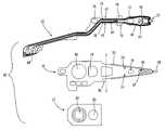
- FIG. 1is a top view of the suspension assembly with side views of the flanges.
- FIG. 2is an exploded top view of the suspension assembly, which includes the flexure assembly, the stainless steel load beam, and the mount plate.
- FIG. 3is an exploded view of the flexure assembly of the suspension as shown in FIG. 1 , including a stainless steel backing layer, a polyimide insulation layer, and a copper trace/conductor lead layer.
- FIG. 4is an enlarged top view of the suspension assembly tip region with all of its component layers: the stainless steel load beam and the three flexure layers (stainless steel trace, polyimide insulation, copper trace/conductor lead).
- FIGS. 5A–5Fare sectional views along different sections of the suspension assembly as shown in FIG. 4 .
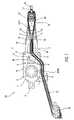
- FIG. 6is an enlarged side view of the suspension assembly tip region as shown in FIG. 1 .
- FIGS. 7A–Care enlarged views of the exploded parts of the flexure assembly tip region as shown in FIG. 3 .
- FIG. 8is a perspective view illustrating loading and unloading of the slider/suspension assembly with respect to the disk.
- FIG. 9is a perspective view of the load/unload ramp dynamics.
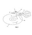
- FIG. 10is a simplified drawing of a magnetic recording disk drive system.
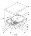
- FIG. 11is a perspective view of a disk drive.
- FIG. 10there is shown a disk drive 120 embodying the suspension of the present invention.
- a disk drive 120embodying the suspension of the present invention.
- at least one rotatable magnetic disk 122is supported on a spindle 126 and rotated by a disk drive motor 130 .
- the magnetic recording media on each diskis in the form of an annular pattern of concentric data tracks (not shown) on the disk 122 .
- At least one slider 124is positioned on the disk 122 , each slider 124 supporting one or more magnetic read/write heads 134 . As the disks rotate, the slider 124 is moved radially in and out over the disk surface 136 so that the heads 134 may access different portions of the disk where desired data is recorded.
- Each slider 124is attached to a positioner arm 132 by means of a suspension 128 to form a head gimbal assembly. The suspension 128 provides a slight spring force, which biases the slider 124 against the disk surface 136 .
- Each positioner arm 132is attached to an actuator 142 .
- the rotation of the disk 122generates an air bearing between the slider 124 and the disk surface 136 which exerts an upward force or lift on the force of the suspension 128 and supports the slider 124 off and slightly above the disk surface by a small, substantially constant spacing during normal operation.
- control signals generated by a control unit 146such as access control signals and internal clock signals.
- the control unit 146comprises logic control circuits, storage chips and a microprocessor.
- the control unit 146generates control signals to control various system operations such as drive motor control signals on line 138 and head position and seek control signals on line 144 .
- the control signals on line 144provide the desired current profiles to optimally move and position the slider 124 to the desired data track on the disk 122 .
- Read and write signalsare communicated to and from the read/write heads 134 by means of a recording channel 140 .
- disk storage systemsmay contain a large number of disks and actuators, and each actuator may support a number of sliders.
- FIG. 11shows a hard disk drive 150 using the suspension of the present invention.
- the cover 154 of the disk driveis shown exploded. In operation, the cover would be disposed on top of the housing 152 .
- the disk drive 150comprises one or more magnetic disks 156 .
- the disksmay be conventional particulate or thin film recording disks, which are capable of storing digital data in concentric tracks. In a preferred embodiment, both sides of the disks 156 are available for storage, and it will be recognized by one of ordinary skill in the art that the disk drive 150 may include any number of such disks 156 .
- the disks 156are mounted to a spindle 158 .
- the spindle 158is attached to a spindle motor (not shown), which rotates the spindle 158 and the disks 156 to provide read/write access to the various portions of the concentric tracks on the disks 156 .
- An actuator assembly 176includes positioner arm 160 , and a suspension assembly 162 .
- the suspension assembly 162includes a slider/transducer assembly 164 at its distal end. Although only one slider/transducer assembly 164 of the suspension assembly 162 is shown, it will be recognized that the disk drive 150 has one slider/transducer assembly 164 for each side of each disk 156 included in the disk drive 150 .
- the actuator assembly 176further comprises a pivot 172 around which the actuator 176 with positioner arm 160 pivots.
- the main function of the actuator assembly 176is to move the positioner arm 160 around the pivot 172 .
- Part of the actuator assembly 176is the voice coil motor (VCM) assembly 174 , which comprises a VCM bottom plate, one or more magnets, and a VCM top plate in combination with an actuator coil.
- VCMvoice coil motor
- Current passing through the actuator coilinteracts with the magnetic field of the magnets to rotate the positioner arm 160 and suspension assembly 162 around the pivot 172 , thus positioning the slider/transducer assembly 164 as desired.
- the actuator assembly 176comprises a plurality of positioner arms 160 fixed in a comb-like arrangement such that the inner arms 165 fit between the disks 156 forming disk stack 170 and the outer arms 166 , 168 extend over the top surface of the top disk and the bottom surface of the bottom disk, respectively.
- the inner arms 165each support two suspension assemblies 162 (upper and lower suspension assemblies) with attached slider/transducer assemblies 164 .
- the upper outer arm 166supports one suspension assembly 162 with its slider/transducer assembly 164 to access data on the top surface of the top disk of disk stack 170 .
- the lower outer arm 168supports one suspension assembly 162 with its slider/transducer assembly 164 to access data on the bottom surface of the bottom disk of disk stack 170 .
- FIG. 1shows a top view of a suspension assembly 10 according to one embodiment of the present invention for use in the disk drive in FIG. 11 .
- FIG. 2shows an exploded top view of the suspension assembly 10 , which includes a flexure assembly 22 , a stainless steel load beam 14 , and a mount plate 12 , attached to each other in that order.
- the suspension assemblycarries at its forward portion a gimballing structure comprising the interaction of the load beam and the flexure and slider/magnetic head combination, and mounts at its rearward portion to the actuator (not shown).
- the suspension assembly 10supports a slider 40 near a limiter 50 and a hook 60 .
- a head lift 58extends from the tip region 15 of the suspension assembly 10 .
- the flexure rear opening 76the load beam mid opening 78 , and the plate opening 80 are lined up as the suspension assembly 10 components are stacked.
- the flexure front opening 72 and the load beam front opening 74are lined up. Swaging hole 82 is shown overlapping over load beam hole 86 .
- FIG. 3is an exploded view of the flexure assembly 22 of the suspension assembly 10 , as shown in FIG. 1 .
- the flexure assembly 22comprises electrical traces 20 , a polyimide insulation 18 , and a stainless steel backing 16 , attached to each other in that order.
- the welding points 4are used to join the parts of the suspension assembly 10 . As can be seen in FIG. 1 , the welding points 4 are placed so that welding only occurs with the stainless steel backing 16 of the suspension assembly 10 , avoiding the polyimide insulation 18 and traces 20 .
- the welding points 4 at wings 70 on the steel backing 16join the flexure assembly 22 to the load beam 14 .
- the flexure assembly 22has read traces 26 and write traces 28 , one end of which terminating at the connector 84 at the rearward portion of the suspension assembly 10 , and another end terminating at the pads 42 near the slider 40 .
- the tracesprovide electrical connections between the read/write heads on the slider and the control system (shown in FIG. 10 ).
- the flexure assembly 22splits into branches 45 and 47 of unequal width at the cutout 44 at the hinge region (line 2 — 2 ) of the suspension assembly 10 .
- the flexure assembly 22has a symmetric boundary for mechanical balance, but it has the asymmetric branches 45 and 47 for improved electrical characteristics of the traces 26 and 28 according to data signal response requirements.
- the asymmetric cutouts 44accommodate different widths of read trace 26 and write trace 28 (see also FIG. 5E ), which are fully backed with stainless steel backing 16 for uniform impedance requirement of high data rate and better structural integrity of the traces as they are subject to flexing during operation.
- the read traces 26are wider than the write traces 28 , thus requiring a wider branch 47 along the flexure assembly 22 .
- FIGS. 1 and 2show that the load beam 14 is pre-bent to define a hinge 46 along line 2 — 2 , which allows bending of the load beam at the hinge during loading and unloading of the slider 40 with respect to the disk. Bending at hinge 46 is in a direction away from the mount plate 12 and towards the flexure assembly 22 , so as to provide a preload spring force on the slider when it is loaded onto the disk.
- FIG. 6shows an enlarged side view of the suspension assembly tip region 15 . In this view, a disk (not shown) rotates below the slider 40 in the direction of the arrow 32 , as an air bearing exists between the disk and the slider 40 .
- the hinge 46allows the load beam 14 to bias the slider 40 towards the surface of the disk during operating conditions.
- a dimple 48 on the load beam 14is used. Since the dimple 48 protrudes toward the flexure assembly 22 , thus towards the slider 40 and the surface of the disk (not shown), the load beam 14 biases the slider 40 to the disk.
- the air bearing, or the cushion on which the slider 40 sits,provides a counterforce to maintain the suspension assembly 10 at the proper distance from the disk.
- the pivoting feature of the dimple 48also provides flexibility in the flexure assembly 22 so that it can adapt to variations in disk surfaces as well as in different disk operating conditions.
- FIGS. 5A–5Eshow sectional views of the suspension assembly 10 as shown in FIG. 4 .
- the edges of the load beam 14are bent, which forms flange 30 , to improve the rigidity of the generally flat load beam 14 .
- the flange 30 of the load beam 14is set at an angle between 30°–60° to the plane of the load beam (e.g., 45°), which would allow an acceptable compromise between high bending stiffness and low flow-induced vibration.
- the lower profile of the load beam 14results in less excitation caused by air turbulence, which maintains adequate stiffness of the load beam 14 .
- FIG. 5Fshows the sectional view of the suspension assembly 10 at the terminating pads 42 .
- This sectional viewtaken along line 5 F— 5 F in FIG. 4 , shows that the size of the copper pad 42 is slightly bigger than that of the insulating pad 43 such that the copper pad 42 extends over the insulating pad 43 on the side of the slider 40 .
- laser solder ball bondingmay be applied to join the contacts of the read/write heads on the side of the slider 40 to the copper pads 42 .
- FIG. 7Cshows the relative placement of the slider 40 , the read/write contacts 41 , and the copper pads 42 .
- the oversized copper pads 42prevent the edges of the polyimide insulation pads 43 underneath them from burning, which may also lead to damage to the entire insulation pads and the insulation under the neighboring traces.
- the electrical traces 20 , insulation 18 , and steel backing 16are stacked, the copper pads 42 and the polyimide insulation pads 43 are suspended over the opening 34 without the support of the stainless steel backing 16 . This configuration prevents potential electrical shorting by the steel backing 16 in the event the insulation pads 43 are defective.
- the width of the tip section of the load beam below the slider 40is about the same or less than the width of the slider 40 .
- the load beamdoes not extend beyond the slider to provide a lift tab to permit head loading and unloading functions.
- the external excitation acting upon the wide load beamresults in torsional (off track) and in-plane bending modes that have lower resonance frequencies during operation of the disk drive, which are undesirable as they affect the dynamic performance of the drive.
- the narrow load beam 14is designed for improved dynamic performance by pushing the resonance modes to higher frequencies while providing head loading and unloading functions.
- FIG. 8shows a simplified view of the movement of the suspension assembly 10 between “load” and “unload” positions with respect to a disk 11 in the disk drive 150 (shown in FIG. 11 ).
- a ramp mechanism 36is employed to lift the heads from each disk surface as the suspension assembly that supports the read/write head travels beyond the disk's perimeter, where the heads are “parked” outside of the disk stack.
- the actuator 76is shown to move the suspension assembly 10 to access the disk surface at the “load” position 19 b and to rest at a parked position 19 a .
- the sectional view of the head lift 58is shown in FIG. 5A , taken along line 5 A— 5 A in FIG. 4 .
- the head lift 58slides over the ramp 36 that extends over the disk surface.
- the curved shape of the head lift 58 and the ramp 36cooperate to create a cam action to lift the load beam and the flexure assembly attached thereto (including the slider 40 ).
- the head lift 58rests at a detent 37 , where the heads are in the parked position.
- the actuator 76is turned to move the suspension assembly 10 towards the disk, such that the slider is lowered and supported on the air bearing formed on the rotating disk surface 11 as the head lift 58 is guided down the ramp 36 .
- descent speed of the slideris controlled by controlling the movement of the actuator.
- FIG. 4is an enlarged top view of a suspension assembly tip region, which includes a flexure tip 15 .
- the tip 15rests above a stop 38 with a small gap 88 .
- the stop 38is made of plastic, and it may be part of or an extension from the ramp 36 .
- FIGS. 2 and 4are top views of the layers of the stainless steel backing 16 and polyimide insulation 18 . In accordance with one embodiment of the present invention, FIG.
- FIG. 6which is an enlarged side view of the suspension assembly tip region, shows that the polyimide insulation tip 68 extends beyond the stainless steel backing tip 66 (see also FIG. 4 ).
- FIG. 5Cwhich is the section taken along line 5 C— 5 C in FIG. 4 , is another view that shows the steel backing 16 with the extended polyimide insulation 18 .
- the flexure insulation tip 68protects the stop 38 from abrasion by the stainless steel backing tip 66 since only the extended insulation tip 68 contacts the supporting stop 38 . Otherwise, the steel backing tip 66 could cut or scrape the plastic stop 38 , causing plastic dust particles that could contaminate the disk drive operating environment, leading to head read/write failure.
- FIG. 6shows only one suspension assembly 10 , ramp 36 , and stop 38 , it is noted that additional components can be stacked to complement a stack of disks in a disk drive assembly.
- the ramps 36 and stops 38may be configured in a generally comb shaped configuration, with each “prong” of the “comb” functionally cooperating with the adjacent surfaces of two adjacent disks.
- FIG. 6shows the relative orientation of the slider 40 and the flexure assembly 22 to a limiter 50 .
- the limiter 50extends generally perpendicularly from the plane of the load beam 14 . Its purpose is for limiting the extent by which the flexure assembly 22 can move away from the load beam 14 . Otherwise, the flexure assembly 22 may be damaged when the separation of the flexure assembly 22 from the load beam 14 exceeds its design limit.
- the limiter 50 on the load beam 14initially lifts the flexure hook 60 of flexure tongue 16 (which supports the slider 40 ) during head loading and unloading operations against the air bearing suction on the slider 40 . As seen in FIG.
- the limiter 50is located at the leading edge 52 side of the slider 40 (the direction of disk rotation is indicated by the arrow 32 ).
- the limiter 50engages with the hook 60 of the stainless steel backing 16 in the flexure assembly 22 .
- the top view in FIG. 4shows the placement required for the limiter 50 and hook 60 during assembly of the flexure assembly 22 to the load beam 14 for proper engagement of the hook 60 and the limiter 50 .
- the limiter 50is shown in its initial configuration as it is formed flat in the plane of the load beam 14 .
- the inner curve 62 of the unbent limiter 50fits with the inner curve 64 of the hook 60 .
- FIG. 5Da sectional view taken along line 5 D— 5 D in FIG.
- FIG. 4shows the engagement of the limiter 50 to the hook 60 of the stainless steel backing 16 , but in this view the limiter 50 is bent from its initial position to a position perpendicular to the plane of the load beam 14 (arrow 39 ).
- the flexure assembly 22 and the load beam 14are formed without having to bend to form a vertical limiter extending from the structures. All components are kept generally flat (see FIG. 4 ) until the last step of manufacturing, in which bending of the limiter 50 is undertaken to position the limiter 50 in a functional manner with respect to the hook 60 .
- Prior art limitershad to be bent prior to assembling the flexure assembly to the load beam.
- the configuration and positioning of the limiter 50also minimizes the possibility of disengagement of the limiter 50 and the hook 60 when the disk drive is subject to high shock.
- Prior art limiter configuration and placementare less secure in the engagement of the flexure assembly 22 when subject to high shock.
- the present invention's placement of the limiter 50improves the functional integrity of the limiter.
- the limiter 50is located at the leading edge 52 side of the slider 40 .
- the tip of the limiter 50points away from the slider 40 .
- the dynamics of the air bearing suctioncauses a positive pitch 56 about the dimple 48 and the slider 40 separated from the dimple 48 .
- the limiter 50With the limiter 50 positioned at the leading edge 52 side of the slider 40 , the positive pitch 56 and the separation between the dimple 48 and the slider 40 tend to cause the flexure hook 60 to move towards the load beam limiter 50 .
- the limiter 50catches against the hook 60 and reduces the likelihood of the limiter 50 disengaging from the hook 60 of the flexure tongue 16 of the flexure assembly 22 . Consequently, the slider 40 and the flexure assembly 22 are less likely to separate from the load beam 14 beyond their design limit.
- an actuator assembly 76comprising a stack of suspension assemblies
- the suspension assembliesshould be maintained separated in a manner that maintains clearance between adjacent sliders.
- the sliders/heads of two opposite facing adjacent suspension assembliesface each other.
- a plastic head separation tool in the shape of a combhas been used in the past to separate the suspension assemblies to prevent damage to the air bearing surface of the slider 40 .
- the finger of the comb shaped toolis inserted between two opposite facing adjacent suspension assemblies.
- dimples 24are provided on the load beam 14 .
- FIG. 5Eshows two dimples 24 , which are aligned transversely relative to the load beam longitudinal axis. The sectional view in FIG.
- 5Eshows wider read trace 26 and narrower write trace 28 that run between the two dimples 24 , which protrude on the side of the traces 26 and 28 .
- the dimples 24serve as cam surfaces for head separation tool insertion between adjacent facing suspension assemblies, and prevent damage to the traces. Given that the head separation tool is made of a plastic material that could otherwise be chipped by the sharp edges of the stainless steel layer 16 of the flexure assembly, the dimples 24 reduce the abrasion against the tool. This in turn reduces stray dust arising from abrasion, which would be damaging to the operation of the disk drive. Although one dimple would suffice for facilitating insertion of the head separation tool, the use of two dimples 24 provides symmetry to allow tool insertion from either side of the load beam 14 .
Landscapes
- Supporting Of Heads In Record-Carrier Devices (AREA)
Abstract
Description
Claims (29)
Priority Applications (2)
| Application Number | Priority Date | Filing Date | Title |
|---|---|---|---|
| US09/676,216US6965501B1 (en) | 2000-09-28 | 2000-09-28 | Integrated lead suspension for high density drive |
| US10/611,080US7137187B2 (en) | 2000-09-28 | 2003-06-30 | Integrated lead suspension for high density drive |
Applications Claiming Priority (1)
| Application Number | Priority Date | Filing Date | Title |
|---|---|---|---|
| US09/676,216US6965501B1 (en) | 2000-09-28 | 2000-09-28 | Integrated lead suspension for high density drive |
Related Child Applications (1)
| Application Number | Title | Priority Date | Filing Date |
|---|---|---|---|
| US10/611,080DivisionUS7137187B2 (en) | 2000-09-28 | 2003-06-30 | Integrated lead suspension for high density drive |
Publications (1)
| Publication Number | Publication Date |
|---|---|
| US6965501B1true US6965501B1 (en) | 2005-11-15 |
Family
ID=31496230
Family Applications (2)
| Application Number | Title | Priority Date | Filing Date |
|---|---|---|---|
| US09/676,216Expired - LifetimeUS6965501B1 (en) | 2000-09-28 | 2000-09-28 | Integrated lead suspension for high density drive |
| US10/611,080Expired - Fee RelatedUS7137187B2 (en) | 2000-09-28 | 2003-06-30 | Integrated lead suspension for high density drive |
Family Applications After (1)
| Application Number | Title | Priority Date | Filing Date |
|---|---|---|---|
| US10/611,080Expired - Fee RelatedUS7137187B2 (en) | 2000-09-28 | 2003-06-30 | Integrated lead suspension for high density drive |
Country Status (1)
| Country | Link |
|---|---|
| US (2) | US6965501B1 (en) |
Cited By (14)
| Publication number | Priority date | Publication date | Assignee | Title |
|---|---|---|---|---|
| US20060044694A1 (en)* | 2002-02-26 | 2006-03-02 | Girard Mark T | Limiter for integral flexible circuit suspension assembly and method of assembling |
| US20060221503A1 (en)* | 2005-03-31 | 2006-10-05 | Nhk Spring Co., Ltd. | Head suspension |
| US20060274454A1 (en)* | 2005-06-02 | 2006-12-07 | Arya Satya P | Stainless steel framework for changing the resonance frequency range of a flexure nose portion of a head gimbal assembly |
| US20070159727A1 (en)* | 2006-01-10 | 2007-07-12 | Arya Satya P | Method and system for utilizing flexible members in a head gimbal assembly to reduce impact of operational disturbances of slider flying height |
| US20080013214A1 (en)* | 2006-07-14 | 2008-01-17 | Seagate Technology Llc | Braced suspension |
| US20080030900A1 (en)* | 2006-08-01 | 2008-02-07 | Sae Magnetics (Hk) Ltd. | Suspension gimbal designs with better dynamic performances |
| US7489477B1 (en)* | 2005-02-15 | 2009-02-10 | Magnecomp Corporation | Delayed limiter positioning in suspension manufacture |
| US20100290160A1 (en)* | 2009-05-15 | 2010-11-18 | Nhk Spring Co., Ltd. | Disk drive flexure |
| US20100296195A1 (en)* | 2009-05-22 | 2010-11-25 | Kabushiki Kaisha Toshiba | Head gimbal assembly and disk drive provided with the same |
| JP2011243267A (en)* | 2010-05-20 | 2011-12-01 | Nitto Denko Corp | Suspension board with circuit and method for manufacturing the same |
| US8208224B1 (en)* | 2011-08-29 | 2012-06-26 | Western Digital Technologies, Inc. | Suspension assemblies for minimizing stress on slider solder joints |
| JP2013004135A (en)* | 2011-06-15 | 2013-01-07 | Dainippon Printing Co Ltd | Substrate for suspension, suspension, suspension with head, and hard disk drive |
| JP2013093071A (en)* | 2011-10-24 | 2013-05-16 | Nhk Spring Co Ltd | Method for manufacturing head suspension and reference pin block |
| JP2015138572A (en)* | 2014-01-24 | 2015-07-30 | エイチジーエスティーネザーランドビーブイ | Features of a two-stage microactuator flexure to minimize electrical shorts |
Families Citing this family (26)
| Publication number | Priority date | Publication date | Assignee | Title |
|---|---|---|---|---|
| JP3997976B2 (en)* | 2003-10-10 | 2007-10-24 | 新科實業有限公司 | Suspension, head gimbal assembly, and disk drive device including the head gimbal assembly |
| US7403357B1 (en) | 2004-08-05 | 2008-07-22 | Maxtor Corporation | Disk drive flexure assembly with a plurality of support bond pad apertures with a bond pad disposed over a bond pad support and part of each support bond pad aperture |
| JP2006053971A (en)* | 2004-08-10 | 2006-02-23 | Hitachi Global Storage Technologies Netherlands Bv | Suspension, magnetic head assembly, and magnetic disk drive |
| US7724476B1 (en)* | 2004-09-16 | 2010-05-25 | Hutchinson Technology Incorporated | Coined headlift with formed rail offset for a disk drive head suspension component |
| US7352534B2 (en)* | 2005-02-11 | 2008-04-01 | Hitachi Global Storage Technologies Netherlands, B.V. | Flexure leg optimization shapes for lateral stiffness |
| US7808744B2 (en)* | 2005-03-11 | 2010-10-05 | Seagate Technology Llc | Apparatus including a dielectric mirror and method of reflecting radiation away from a portion of an apparatus |
| JP4965835B2 (en)* | 2005-03-25 | 2012-07-04 | キヤノン株式会社 | Structure, manufacturing method thereof, and device using the structure |
| JP4455408B2 (en)* | 2005-05-31 | 2010-04-21 | 東芝ストレージデバイス株式会社 | Head support device and drive having the same |
| US20060274453A1 (en)* | 2005-06-02 | 2006-12-07 | Arya Satya P | Method for utilizing a stainless steel framework for changing the resonance frequency range of a flexure nose portion of a head gimbal assembly |
| US20060274452A1 (en)* | 2005-06-02 | 2006-12-07 | Arya Satya P | Method for utilizing a suspension flexure polyimide material web to dampen a flexure nose portion of a head gimbal assembly |
| US20060274451A1 (en)* | 2005-06-02 | 2006-12-07 | Arya Satya P | Suspension flexure polyimide material web for damping a flexure nose portion of a head gimbal assembly |
| JP4191720B2 (en)* | 2005-11-01 | 2008-12-03 | Tdk株式会社 | Magnetic head assembly |
| JP4390778B2 (en)* | 2006-03-13 | 2009-12-24 | 富士通株式会社 | Magnetic head assembly |
| US20070285842A1 (en) | 2006-06-08 | 2007-12-13 | Momo Boljanovic | Method and apparatus for a base plate used in a head gimbal assembly of a hard disk drive |
| US7567410B1 (en)* | 2006-10-31 | 2009-07-28 | Western Digital Technologies, Inc. | Flexure including a heat sink and a dielectric layer under trace termination pads |
| US7830638B1 (en) | 2007-08-13 | 2010-11-09 | Magnecomp Corporation | Structure and method for localizing solder ball strain on hard disk drive suspension gimbal |
| JP4986917B2 (en) | 2008-04-21 | 2012-07-25 | ヒタチグローバルストレージテクノロジーズネザーランドビーブイ | Suspension and disk drive device |
| US8194354B1 (en) | 2008-05-23 | 2012-06-05 | Western Digital Technologies, Inc. | Suspension assembly including a flexure tail with staggered rows of apertures |
| US8233240B2 (en)* | 2009-12-10 | 2012-07-31 | Hitachi Global Storage Technologies Netherlands B.V. | Magnetic recording disk drive with integrated lead suspension having multiple segments for optimal characteristic impedance |
| JP5591602B2 (en)* | 2010-06-24 | 2014-09-17 | 日本発條株式会社 | Flexure and wiring portion forming method thereof |
| CN107305775B (en)* | 2016-04-25 | 2019-08-30 | 株式会社东芝 | Suspension assembly with lift vane, disk drive, and method of making a lift vane of a suspension assembly |
| US10395675B1 (en)* | 2018-03-26 | 2019-08-27 | International Business Machines Corporation | Stress-free tape head module |
| JP7314081B2 (en)* | 2020-03-11 | 2023-07-25 | 日本発條株式会社 | Disk device suspension |
| CN111935934A (en)* | 2020-09-10 | 2020-11-13 | 合肥言臻科技有限公司 | Limiting mechanism frame for assembling electric power cabinet |
| US11189306B1 (en) | 2020-12-08 | 2021-11-30 | International Business Machines Corporation | Reduced-stress tape head module |
| JP2022147507A (en)* | 2021-03-23 | 2022-10-06 | 株式会社東芝 | disk device |
Citations (41)
| Publication number | Priority date | Publication date | Assignee | Title |
|---|---|---|---|---|
| US4761699A (en)* | 1986-10-28 | 1988-08-02 | International Business Machines Corporation | Slider-suspension assembly and method for attaching a slider to a suspension in a data recording disk file |
| JPH0845207A (en) | 1994-07-29 | 1996-02-16 | Sony Corp | Magnetic head for disk device |
| JPH1055636A (en)* | 1996-05-23 | 1998-02-24 | Hutchinson Technol Inc | Suspension assembly and forming method of deflection part thereof |
| US5737152A (en)* | 1995-10-27 | 1998-04-07 | Quantum Corporation | Suspension with multi-layered integrated conductor trace array for optimized electrical parameters |
| US5739982A (en)* | 1996-08-23 | 1998-04-14 | International Business Machines Corporation | Laser treatment of head gimbal assembly components |
| US5812342A (en) | 1996-11-27 | 1998-09-22 | Magnecomp Corporation | Reduced mass load beam with improved stiffness properties |
| US5812344A (en)* | 1997-05-12 | 1998-09-22 | Quantum Corporation | Suspension with integrated conductor trace array having optimized cross-sectional high frequency current density |
| JPH117741A (en) | 1997-06-16 | 1999-01-12 | Alps Electric Co Ltd | Magnetic head apparatus |
| US5864445A (en)* | 1994-04-15 | 1999-01-26 | Hutchinson Technology Incorporated | Hygrothermal load compensating structures in an integrated lead suspension |
| US5877923A (en) | 1995-08-21 | 1999-03-02 | Read Rite Corporation | Head suspension assembly |
| US5877921A (en) | 1997-05-14 | 1999-03-02 | Magnecomp Corp. | High shock suspension with load beam shielded flexure |
| US5892637A (en) | 1996-05-10 | 1999-04-06 | International Business Machines Corporation | Multi-piece integrated suspension assembly for a magnetic storage system |
| US5894381A (en) | 1997-01-24 | 1999-04-13 | Read-Rite Corporation | Low mass sectioned load beam of head gimbal assembly having increased high first torsion frequency mode |
| US5930079A (en) | 1996-08-21 | 1999-07-27 | Magnecomp Corp. | Suspension having limited travel flexure for improved loadability |
| US5982584A (en)* | 1996-12-19 | 1999-11-09 | Hutchinson Technology Incorporated | Integrated lead suspension flexure with serially arranged metal-backed and suspended insulator portions for hygrothermal compensation |
| US5986853A (en)* | 1997-07-08 | 1999-11-16 | International Business Machines Corporation | Transducer suspension system |
| US6014290A (en)* | 1996-09-12 | 2000-01-11 | Hutchinson Technology Incorporated | Head suspension having conductor protecting standoffs |
| US6021022A (en) | 1997-10-27 | 2000-02-01 | Seagate Technology, Inc. | Flexure displacement limiter-flex circuit interconnect |
| JP2000076810A (en) | 1998-08-28 | 2000-03-14 | Hitachi Ltd | Magnetic head support mechanism |
| US6043955A (en) | 1998-02-19 | 2000-03-28 | Magnecomp Corp. | Three piece suspension with framed gimbal flexure |
| US6046883A (en)* | 1996-12-31 | 2000-04-04 | Hutchinson Technology Incorporated | Head suspension having a flexure motion limiter |
| JP2000195209A (en) | 1999-01-04 | 2000-07-14 | Nhk Spring Co Ltd | Suspension for disk drive |
| US6137657A (en) | 1998-03-25 | 2000-10-24 | Magnecomp Corp. | Suspension flexure with load-unload efficient motion limiting feature |
| US6151197A (en)* | 1998-12-30 | 2000-11-21 | Western Digital Corporation | Water slide suspension assembly having a stiffened vertically offset lift tab |
| JP2000348454A (en) | 1999-06-07 | 2000-12-15 | Internatl Business Mach Corp <Ibm> | Head support arm, its manufacture, and data recording apparatus |
| US6172853B1 (en)* | 1999-05-20 | 2001-01-09 | Hutchinson Technology Incorporated | Head suspension having a near dimple motion limiter |
| US6181525B1 (en) | 1998-09-23 | 2001-01-30 | Read-Rite Corporation | Read/write head with a limited range of motion relative to a load beam |
| US6191915B1 (en)* | 1997-11-06 | 2001-02-20 | Nhk Spring Co., Ltd. | Suspension for disc drive that is capable of restraining excessive inclination of a head or occurrence of dimple separation when it is shocked, without enhancing the stiffness of a flexure |
| US6195237B1 (en)* | 1999-08-26 | 2001-02-27 | Magnecomp Corp. | Flexure limiter with snagging feature |
| US6233121B1 (en) | 1999-04-09 | 2001-05-15 | International Business Machines Corporation | Magnetic disk drive suspension pitch motion limiter |
| US6243235B1 (en)* | 1999-04-16 | 2001-06-05 | International Business Machines Corporation | Transducer suspension system with limiter |
| US6266212B1 (en) | 1997-10-28 | 2001-07-24 | Magnecomp Corp. | High shock suspension with tethered flexure tongue |
| US6292333B1 (en)* | 1999-02-11 | 2001-09-18 | Western Digital Technologies, Inc. | Disk drive having an I.D. ramp loading system employing multiple-function spacer structure |
| US6320729B1 (en) | 1999-04-27 | 2001-11-20 | Magnecomp Corp. | Snap-in assembly of suspension limiter having both high shock and load/unload cycle capability |
| US20020051324A1 (en) | 2000-10-30 | 2002-05-02 | Nhk Spring Co., Ltd. | Suspension for disc drive |
| US20020075602A1 (en) | 2000-12-15 | 2002-06-20 | Mangold Markus E. | Head gimbal assembly flexure arm displacement limiter |
| US6424499B1 (en)* | 1999-03-31 | 2002-07-23 | Quantum Corporation | Flexible trace interconnect array for multi-channel tape head |
| US6424498B1 (en)* | 1999-12-03 | 2002-07-23 | Seagate Technology Llc | Shock resistant suspension limiter for a disc drive |
| US6538850B1 (en) | 1999-10-06 | 2003-03-25 | Read-Rite Corporation | Low profile head gimbal assembly with shock limiting and load/unload capability and method of manufacture thereof |
| US6611402B1 (en) | 1999-06-09 | 2003-08-26 | Seagate Technology Llc | Pitch-adjustable head suspension with end lift tab for dynamic load/unload |
| US6667856B2 (en)* | 1999-12-27 | 2003-12-23 | Hutchinson Technology Incorporated | Head suspension with integral shock limiter |
- 2000
- 2000-09-28USUS09/676,216patent/US6965501B1/ennot_activeExpired - Lifetime
- 2003
- 2003-06-30USUS10/611,080patent/US7137187B2/ennot_activeExpired - Fee Related
Patent Citations (47)
| Publication number | Priority date | Publication date | Assignee | Title |
|---|---|---|---|---|
| US4761699A (en)* | 1986-10-28 | 1988-08-02 | International Business Machines Corporation | Slider-suspension assembly and method for attaching a slider to a suspension in a data recording disk file |
| US5864445A (en)* | 1994-04-15 | 1999-01-26 | Hutchinson Technology Incorporated | Hygrothermal load compensating structures in an integrated lead suspension |
| JPH0845207A (en) | 1994-07-29 | 1996-02-16 | Sony Corp | Magnetic head for disk device |
| US5877923A (en) | 1995-08-21 | 1999-03-02 | Read Rite Corporation | Head suspension assembly |
| US5737152A (en)* | 1995-10-27 | 1998-04-07 | Quantum Corporation | Suspension with multi-layered integrated conductor trace array for optimized electrical parameters |
| US5892637A (en) | 1996-05-10 | 1999-04-06 | International Business Machines Corporation | Multi-piece integrated suspension assembly for a magnetic storage system |
| JPH1055636A (en)* | 1996-05-23 | 1998-02-24 | Hutchinson Technol Inc | Suspension assembly and forming method of deflection part thereof |
| US5771136A (en)* | 1996-05-23 | 1998-06-23 | Hutchinson Technology Incorporated | Suspension assembly for mounting a head slider having a flexure with a shock limiter |
| US5930079A (en) | 1996-08-21 | 1999-07-27 | Magnecomp Corp. | Suspension having limited travel flexure for improved loadability |
| US5739982A (en)* | 1996-08-23 | 1998-04-14 | International Business Machines Corporation | Laser treatment of head gimbal assembly components |
| US6014290A (en)* | 1996-09-12 | 2000-01-11 | Hutchinson Technology Incorporated | Head suspension having conductor protecting standoffs |
| US5812342A (en) | 1996-11-27 | 1998-09-22 | Magnecomp Corporation | Reduced mass load beam with improved stiffness properties |
| US6018871A (en) | 1996-11-27 | 2000-02-01 | Magnecomp Corp. | Method for manufacturing a reduced mass load beam with improved stiffness properties |
| US5982584A (en)* | 1996-12-19 | 1999-11-09 | Hutchinson Technology Incorporated | Integrated lead suspension flexure with serially arranged metal-backed and suspended insulator portions for hygrothermal compensation |
| US6046883A (en)* | 1996-12-31 | 2000-04-04 | Hutchinson Technology Incorporated | Head suspension having a flexure motion limiter |
| US5894381A (en) | 1997-01-24 | 1999-04-13 | Read-Rite Corporation | Low mass sectioned load beam of head gimbal assembly having increased high first torsion frequency mode |
| US5812344A (en)* | 1997-05-12 | 1998-09-22 | Quantum Corporation | Suspension with integrated conductor trace array having optimized cross-sectional high frequency current density |
| US5877921A (en) | 1997-05-14 | 1999-03-02 | Magnecomp Corp. | High shock suspension with load beam shielded flexure |
| JPH117741A (en) | 1997-06-16 | 1999-01-12 | Alps Electric Co Ltd | Magnetic head apparatus |
| US5986853A (en)* | 1997-07-08 | 1999-11-16 | International Business Machines Corporation | Transducer suspension system |
| US6021022A (en) | 1997-10-27 | 2000-02-01 | Seagate Technology, Inc. | Flexure displacement limiter-flex circuit interconnect |
| US6266212B1 (en) | 1997-10-28 | 2001-07-24 | Magnecomp Corp. | High shock suspension with tethered flexure tongue |
| US6191915B1 (en)* | 1997-11-06 | 2001-02-20 | Nhk Spring Co., Ltd. | Suspension for disc drive that is capable of restraining excessive inclination of a head or occurrence of dimple separation when it is shocked, without enhancing the stiffness of a flexure |
| US6043955A (en) | 1998-02-19 | 2000-03-28 | Magnecomp Corp. | Three piece suspension with framed gimbal flexure |
| US6137657A (en) | 1998-03-25 | 2000-10-24 | Magnecomp Corp. | Suspension flexure with load-unload efficient motion limiting feature |
| US6367145B1 (en) | 1998-03-25 | 2002-04-09 | Magnecomp Corp. | Method of making a suspension flexure with load-unload efficient motion limiting feature |
| JP2000076810A (en) | 1998-08-28 | 2000-03-14 | Hitachi Ltd | Magnetic head support mechanism |
| US6181525B1 (en) | 1998-09-23 | 2001-01-30 | Read-Rite Corporation | Read/write head with a limited range of motion relative to a load beam |
| US6151197A (en)* | 1998-12-30 | 2000-11-21 | Western Digital Corporation | Water slide suspension assembly having a stiffened vertically offset lift tab |
| US6388843B1 (en)* | 1999-01-04 | 2002-05-14 | Nhk Spring Co., Ltd. | Suspension for disc drive |
| JP2000195209A (en) | 1999-01-04 | 2000-07-14 | Nhk Spring Co Ltd | Suspension for disk drive |
| US6292333B1 (en)* | 1999-02-11 | 2001-09-18 | Western Digital Technologies, Inc. | Disk drive having an I.D. ramp loading system employing multiple-function spacer structure |
| US6445546B1 (en)* | 1999-03-24 | 2002-09-03 | Magnecomp Corporation | Snap-in assembly of suspension limiter having both high shock and load/unload cycle capability |
| US6424499B1 (en)* | 1999-03-31 | 2002-07-23 | Quantum Corporation | Flexible trace interconnect array for multi-channel tape head |
| US6233121B1 (en) | 1999-04-09 | 2001-05-15 | International Business Machines Corporation | Magnetic disk drive suspension pitch motion limiter |
| US6243235B1 (en)* | 1999-04-16 | 2001-06-05 | International Business Machines Corporation | Transducer suspension system with limiter |
| US6320729B1 (en) | 1999-04-27 | 2001-11-20 | Magnecomp Corp. | Snap-in assembly of suspension limiter having both high shock and load/unload cycle capability |
| US6172853B1 (en)* | 1999-05-20 | 2001-01-09 | Hutchinson Technology Incorporated | Head suspension having a near dimple motion limiter |
| JP2000348454A (en) | 1999-06-07 | 2000-12-15 | Internatl Business Mach Corp <Ibm> | Head support arm, its manufacture, and data recording apparatus |
| US6611402B1 (en) | 1999-06-09 | 2003-08-26 | Seagate Technology Llc | Pitch-adjustable head suspension with end lift tab for dynamic load/unload |
| US6195237B1 (en)* | 1999-08-26 | 2001-02-27 | Magnecomp Corp. | Flexure limiter with snagging feature |
| US6426851B1 (en) | 1999-08-26 | 2002-07-30 | Magnecomp Corporation | Flexure limiter with snagging feature |
| US6538850B1 (en) | 1999-10-06 | 2003-03-25 | Read-Rite Corporation | Low profile head gimbal assembly with shock limiting and load/unload capability and method of manufacture thereof |
| US6424498B1 (en)* | 1999-12-03 | 2002-07-23 | Seagate Technology Llc | Shock resistant suspension limiter for a disc drive |
| US6667856B2 (en)* | 1999-12-27 | 2003-12-23 | Hutchinson Technology Incorporated | Head suspension with integral shock limiter |
| US20020051324A1 (en) | 2000-10-30 | 2002-05-02 | Nhk Spring Co., Ltd. | Suspension for disc drive |
| US20020075602A1 (en) | 2000-12-15 | 2002-06-20 | Mangold Markus E. | Head gimbal assembly flexure arm displacement limiter |
Cited By (28)
| Publication number | Priority date | Publication date | Assignee | Title |
|---|---|---|---|---|
| US20060044694A1 (en)* | 2002-02-26 | 2006-03-02 | Girard Mark T | Limiter for integral flexible circuit suspension assembly and method of assembling |
| US7386932B2 (en)* | 2002-02-26 | 2008-06-17 | Applied Kinetics, Inc. | Limiter for integral flexible circuit suspension assembly and method of assembling |
| US7489477B1 (en)* | 2005-02-15 | 2009-02-10 | Magnecomp Corporation | Delayed limiter positioning in suspension manufacture |
| US20060221503A1 (en)* | 2005-03-31 | 2006-10-05 | Nhk Spring Co., Ltd. | Head suspension |
| US7688549B2 (en)* | 2005-03-31 | 2010-03-30 | Nhk Spring Co., Ltd. | Head suspension |
| US20060274454A1 (en)* | 2005-06-02 | 2006-12-07 | Arya Satya P | Stainless steel framework for changing the resonance frequency range of a flexure nose portion of a head gimbal assembly |
| US20070159727A1 (en)* | 2006-01-10 | 2007-07-12 | Arya Satya P | Method and system for utilizing flexible members in a head gimbal assembly to reduce impact of operational disturbances of slider flying height |
| US7535678B2 (en)* | 2006-01-10 | 2009-05-19 | Hitachi Global Storage Technologies Netherlands B.V. | Method and system for utilizing flexible members in a head gimbal assembly to reduce impact of operational disturbances of slider flying height |
| US7660073B2 (en) | 2006-07-14 | 2010-02-09 | Seagate Technology Llc | Braced suspension for supporting a head slider |
| US20080013214A1 (en)* | 2006-07-14 | 2008-01-17 | Seagate Technology Llc | Braced suspension |
| US8218269B2 (en) | 2006-08-01 | 2012-07-10 | Sae Magnetics (Hk) Ltd. | Gimbal mounted slider assembly with ramp limiter transverse bar |
| JP2008041241A (en)* | 2006-08-01 | 2008-02-21 | Shinka Jitsugyo Kk | Gimbal structure |
| US20100172057A1 (en)* | 2006-08-01 | 2010-07-08 | Sae Magnetics (Hk) Ltd. | Suspension gimbal designs with better dynamic performances |
| US7684154B2 (en) | 2006-08-01 | 2010-03-23 | Sae Magnetics (Hk) Ltd. | Suspension gimbal designs with better dynamic performances |
| US8000061B2 (en) | 2006-08-01 | 2011-08-16 | Sae Magnetics (Hk) Ltd. | Gimbal mounted slider assembly with transverse bars connecting inner edges of ramp limiter arms |
| US20080030900A1 (en)* | 2006-08-01 | 2008-02-07 | Sae Magnetics (Hk) Ltd. | Suspension gimbal designs with better dynamic performances |
| US8111483B2 (en)* | 2009-05-15 | 2012-02-07 | Nhk Spring Co., Ltd. | Disk drive flexure |
| US20100290160A1 (en)* | 2009-05-15 | 2010-11-18 | Nhk Spring Co., Ltd. | Disk drive flexure |
| US20100296195A1 (en)* | 2009-05-22 | 2010-11-25 | Kabushiki Kaisha Toshiba | Head gimbal assembly and disk drive provided with the same |
| US8059369B2 (en)* | 2009-05-22 | 2011-11-15 | Kabushiki Kaisha Toshiba | Head gimbal assembly and disk drive provided with the same |
| JP2011243267A (en)* | 2010-05-20 | 2011-12-01 | Nitto Denko Corp | Suspension board with circuit and method for manufacturing the same |
| US8858810B2 (en) | 2010-05-20 | 2014-10-14 | Nitto Denko Corporation | Method of producing a suspension board with circuit |
| JP2013004135A (en)* | 2011-06-15 | 2013-01-07 | Dainippon Printing Co Ltd | Substrate for suspension, suspension, suspension with head, and hard disk drive |
| US8208224B1 (en)* | 2011-08-29 | 2012-06-26 | Western Digital Technologies, Inc. | Suspension assemblies for minimizing stress on slider solder joints |
| JP2013093071A (en)* | 2011-10-24 | 2013-05-16 | Nhk Spring Co Ltd | Method for manufacturing head suspension and reference pin block |
| US9296070B2 (en) | 2011-10-24 | 2016-03-29 | Nhk Spring Co., Ltd. | Method of manufacturing head suspension having load beam and flexure aligned with load beam and reference pin block used for the method |
| US10141015B2 (en) | 2011-10-24 | 2018-11-27 | Nhk Spring Co., Ltd. | Reference block configured for use in a method of manufacturing a head suspension having a load beam and a flexure |
| JP2015138572A (en)* | 2014-01-24 | 2015-07-30 | エイチジーエスティーネザーランドビーブイ | Features of a two-stage microactuator flexure to minimize electrical shorts |
Also Published As
| Publication number | Publication date |
|---|---|
| US7137187B2 (en) | 2006-11-21 |
| US20040027725A1 (en) | 2004-02-12 |
Similar Documents
| Publication | Publication Date | Title |
|---|---|---|
| US6965501B1 (en) | Integrated lead suspension for high density drive | |
| US7719796B2 (en) | Suspension for hard disk drive which enables easy dynamic electric testing | |
| US7551402B2 (en) | Magnetic disk drive and ramp | |
| US6965500B1 (en) | Suspension design for attenuation of disk flutter induced track mis-registration of a hard disk drive by manipulation of load beam pitch angle | |
| KR100275179B1 (en) | Disc driver apparatus | |
| US6243235B1 (en) | Transducer suspension system with limiter | |
| US7609483B2 (en) | Data storage device with load/unload tab inclined towards a disk | |
| CN113362861B (en) | Suspension assembly and disk device | |
| US8976491B1 (en) | Disk drive head suspension distal non-op shock limiter with branched arms | |
| US7130157B2 (en) | Head suspension having a displacement limiter | |
| US7859793B2 (en) | Magnetic head assembly that facilitates recovery of a magnetic head slider | |
| JPH0887846A (en) | Suspension system | |
| JPH0798949A (en) | Suspension system | |
| JP2001143422A (en) | Head suspension, head assembly, and disk device | |
| JP4302162B2 (en) | Head actuator assembly and magnetic disk drive equipped with the same | |
| US6747849B1 (en) | High performance suspension with reduced flow-induced vibration | |
| US20070188929A1 (en) | Actuator Load/Unload Ramp | |
| US8102627B2 (en) | Slider suspension assembly having limiter tab passing through load beam hole both within slider silhouette | |
| US7688553B1 (en) | Thermally-compensating attachment of disk drive slider to flexure | |
| US7450347B2 (en) | Head suspension with bridge portion separating apertures near lift tab | |
| US7583474B2 (en) | Suspension and limiter mechanism for a data storage device | |
| US7787218B2 (en) | Data storage device | |
| US7027266B2 (en) | Head suspension with flexure-supported slider between first and second load bending portions | |
| US6381101B1 (en) | Non contact head load/unload apparatus and method for disc drives | |
| US7830639B2 (en) | Data storage device and disk drive |
Legal Events
| Date | Code | Title | Description |
|---|---|---|---|
| AS | Assignment | Owner name:INTERNATIONAL BUSINESS MACHINES CORPORATION, NEW Y Free format text:ASSIGNMENT OF ASSIGNORS INTEREST;ASSIGNORS:PAN, TZONG-SHII S.;PATTANAIK, SURYA;REEL/FRAME:011310/0931;SIGNING DATES FROM 20001117 TO 20001127 | |
| AS | Assignment | Owner name:HITACHI GLOBAL STORAGE TECHNOLOGIES NETHERLANDS B. Free format text:ASSIGNMENT OF ASSIGNORS INTEREST;ASSIGNOR:INTERNATIONAL BUSINESS MACHINES CORPORATION;REEL/FRAME:013993/0037 Effective date:20030716 | |
| STCF | Information on status: patent grant | Free format text:PATENTED CASE | |
| FEPP | Fee payment procedure | Free format text:PAYER NUMBER DE-ASSIGNED (ORIGINAL EVENT CODE: RMPN); ENTITY STATUS OF PATENT OWNER: LARGE ENTITY Free format text:PAYOR NUMBER ASSIGNED (ORIGINAL EVENT CODE: ASPN); ENTITY STATUS OF PATENT OWNER: LARGE ENTITY | |
| FPAY | Fee payment | Year of fee payment:4 | |
| AS | Assignment | Owner name:HGST, NETHERLANDS B.V., NETHERLANDS Free format text:CHANGE OF NAME;ASSIGNOR:HGST, NETHERLANDS B.V.;REEL/FRAME:029341/0777 Effective date:20120723 Owner name:HGST NETHERLANDS B.V., NETHERLANDS Free format text:CHANGE OF NAME;ASSIGNOR:HITACHI GLOBAL STORAGE TECHNOLOGIES NETHERLANDS B.V.;REEL/FRAME:029341/0777 Effective date:20120723 | |
| FPAY | Fee payment | Year of fee payment:8 | |
| AS | Assignment | Owner name:WESTERN DIGITAL TECHNOLOGIES, INC., CALIFORNIA Free format text:ASSIGNMENT OF ASSIGNORS INTEREST;ASSIGNOR:HGST NETHERLANDS B.V.;REEL/FRAME:040820/0802 Effective date:20160831 | |
| FPAY | Fee payment | Year of fee payment:12 | |
| AS | Assignment | Owner name:JPMORGAN CHASE BANK, N.A., AS AGENT, ILLINOIS Free format text:SECURITY INTEREST;ASSIGNOR:WESTERN DIGITAL TECHNOLOGIES, INC.;REEL/FRAME:052915/0566 Effective date:20200113 | |
| AS | Assignment | Owner name:WESTERN DIGITAL TECHNOLOGIES, INC., CALIFORNIA Free format text:RELEASE OF SECURITY INTEREST AT REEL 052915 FRAME 0566;ASSIGNOR:JPMORGAN CHASE BANK, N.A.;REEL/FRAME:059127/0001 Effective date:20220203 |