US6965183B2 - Architecture for electric machine - Google Patents
Architecture for electric machineDownload PDFInfo
- Publication number
- US6965183B2 US6965183B2US10/444,952US44495203AUS6965183B2US 6965183 B2US6965183 B2US 6965183B2US 44495203 AUS44495203 AUS 44495203AUS 6965183 B2US6965183 B2US 6965183B2
- Authority
- US
- United States
- Prior art keywords
- winding
- stator
- rotor
- machine
- current
- Prior art date
- Legal status (The legal status is an assumption and is not a legal conclusion. Google has not performed a legal analysis and makes no representation as to the accuracy of the status listed.)
- Expired - Lifetime, expires
Links
Images


Classifications
- H—ELECTRICITY
- H02—GENERATION; CONVERSION OR DISTRIBUTION OF ELECTRIC POWER
- H02K—DYNAMO-ELECTRIC MACHINES
- H02K21/00—Synchronous motors having permanent magnets; Synchronous generators having permanent magnets
- H02K21/02—Details
- H02K21/04—Windings on magnets for additional excitation ; Windings and magnets for additional excitation
- H02K21/046—Windings on magnets for additional excitation ; Windings and magnets for additional excitation with rotating permanent magnets and stationary field winding
- H—ELECTRICITY
- H02—GENERATION; CONVERSION OR DISTRIBUTION OF ELECTRIC POWER
- H02K—DYNAMO-ELECTRIC MACHINES
- H02K1/00—Details of the magnetic circuit
- H02K1/06—Details of the magnetic circuit characterised by the shape, form or construction
- H02K1/22—Rotating parts of the magnetic circuit
- H02K1/27—Rotor cores with permanent magnets
- H02K1/2786—Outer rotors
- H02K1/2787—Outer rotors the magnetisation axis of the magnets being perpendicular to the rotor axis
- H02K1/2789—Outer rotors the magnetisation axis of the magnets being perpendicular to the rotor axis the rotor consisting of two or more circumferentially positioned magnets
- H02K1/2791—Surface mounted magnets; Inset magnets
- H—ELECTRICITY
- H02—GENERATION; CONVERSION OR DISTRIBUTION OF ELECTRIC POWER
- H02K—DYNAMO-ELECTRIC MACHINES
- H02K16/00—Machines with more than one rotor or stator
- H02K16/04—Machines with one rotor and two stators
- H—ELECTRICITY
- H02—GENERATION; CONVERSION OR DISTRIBUTION OF ELECTRIC POWER
- H02K—DYNAMO-ELECTRIC MACHINES
- H02K21/00—Synchronous motors having permanent magnets; Synchronous generators having permanent magnets
- H02K21/12—Synchronous motors having permanent magnets; Synchronous generators having permanent magnets with stationary armatures and rotating magnets
- H02K21/22—Synchronous motors having permanent magnets; Synchronous generators having permanent magnets with stationary armatures and rotating magnets with magnets rotating around the armatures, e.g. flywheel magnetos
- H—ELECTRICITY
- H02—GENERATION; CONVERSION OR DISTRIBUTION OF ELECTRIC POWER
- H02K—DYNAMO-ELECTRIC MACHINES
- H02K3/00—Details of windings
- H02K3/04—Windings characterised by the conductor shape, form or construction, e.g. with bar conductors
- H02K3/12—Windings characterised by the conductor shape, form or construction, e.g. with bar conductors arranged in slots
- H02K3/16—Windings characterised by the conductor shape, form or construction, e.g. with bar conductors arranged in slots for auxiliary purposes, e.g. damping or commutating
- H—ELECTRICITY
- H02—GENERATION; CONVERSION OR DISTRIBUTION OF ELECTRIC POWER
- H02K—DYNAMO-ELECTRIC MACHINES
- H02K3/00—Details of windings
- H02K3/04—Windings characterised by the conductor shape, form or construction, e.g. with bar conductors
- H02K3/28—Layout of windings or of connections between windings
- H—ELECTRICITY
- H02—GENERATION; CONVERSION OR DISTRIBUTION OF ELECTRIC POWER
- H02K—DYNAMO-ELECTRIC MACHINES
- H02K3/00—Details of windings
- H02K3/46—Fastening of windings on the stator or rotor structure
- H—ELECTRICITY
- H02—GENERATION; CONVERSION OR DISTRIBUTION OF ELECTRIC POWER
- H02K—DYNAMO-ELECTRIC MACHINES
- H02K7/00—Arrangements for handling mechanical energy structurally associated with dynamo-electric machines, e.g. structural association with mechanical driving motors or auxiliary dynamo-electric machines
- H02K7/18—Structural association of electric generators with mechanical driving motors, e.g. with turbines
- H02K7/1807—Rotary generators
- H02K7/1823—Rotary generators structurally associated with turbines or similar engines
- H—ELECTRICITY
- H02—GENERATION; CONVERSION OR DISTRIBUTION OF ELECTRIC POWER
- H02M—APPARATUS FOR CONVERSION BETWEEN AC AND AC, BETWEEN AC AND DC, OR BETWEEN DC AND DC, AND FOR USE WITH MAINS OR SIMILAR POWER SUPPLY SYSTEMS; CONVERSION OF DC OR AC INPUT POWER INTO SURGE OUTPUT POWER; CONTROL OR REGULATION THEREOF
- H02M7/00—Conversion of AC power input into DC power output; Conversion of DC power input into AC power output
- H—ELECTRICITY
- H02—GENERATION; CONVERSION OR DISTRIBUTION OF ELECTRIC POWER
- H02P—CONTROL OR REGULATION OF ELECTRIC MOTORS, ELECTRIC GENERATORS OR DYNAMO-ELECTRIC CONVERTERS; CONTROLLING TRANSFORMERS, REACTORS OR CHOKE COILS
- H02P9/00—Arrangements for controlling electric generators for the purpose of obtaining a desired output
- H02P9/02—Details of the control
- H—ELECTRICITY
- H02—GENERATION; CONVERSION OR DISTRIBUTION OF ELECTRIC POWER
- H02K—DYNAMO-ELECTRIC MACHINES
- H02K21/00—Synchronous motors having permanent magnets; Synchronous generators having permanent magnets
- H02K21/12—Synchronous motors having permanent magnets; Synchronous generators having permanent magnets with stationary armatures and rotating magnets
- H02K21/14—Synchronous motors having permanent magnets; Synchronous generators having permanent magnets with stationary armatures and rotating magnets with magnets rotating within the armatures
- H—ELECTRICITY
- H02—GENERATION; CONVERSION OR DISTRIBUTION OF ELECTRIC POWER
- H02P—CONTROL OR REGULATION OF ELECTRIC MOTORS, ELECTRIC GENERATORS OR DYNAMO-ELECTRIC CONVERTERS; CONTROLLING TRANSFORMERS, REACTORS OR CHOKE COILS
- H02P2101/00—Special adaptation of control arrangements for generators
- H02P2101/30—Special adaptation of control arrangements for generators for aircraft
- Y—GENERAL TAGGING OF NEW TECHNOLOGICAL DEVELOPMENTS; GENERAL TAGGING OF CROSS-SECTIONAL TECHNOLOGIES SPANNING OVER SEVERAL SECTIONS OF THE IPC; TECHNICAL SUBJECTS COVERED BY FORMER USPC CROSS-REFERENCE ART COLLECTIONS [XRACs] AND DIGESTS
- Y10—TECHNICAL SUBJECTS COVERED BY FORMER USPC
- Y10T—TECHNICAL SUBJECTS COVERED BY FORMER US CLASSIFICATION
- Y10T29/00—Metal working
- Y10T29/49—Method of mechanical manufacture
- Y10T29/49002—Electrical device making
- Y10T29/49009—Dynamoelectric machine
- Y—GENERAL TAGGING OF NEW TECHNOLOGICAL DEVELOPMENTS; GENERAL TAGGING OF CROSS-SECTIONAL TECHNOLOGIES SPANNING OVER SEVERAL SECTIONS OF THE IPC; TECHNICAL SUBJECTS COVERED BY FORMER USPC CROSS-REFERENCE ART COLLECTIONS [XRACs] AND DIGESTS
- Y10—TECHNICAL SUBJECTS COVERED BY FORMER USPC
- Y10T—TECHNICAL SUBJECTS COVERED BY FORMER US CLASSIFICATION
- Y10T29/00—Metal working
- Y10T29/49—Method of mechanical manufacture
- Y10T29/49002—Electrical device making
- Y10T29/4902—Electromagnet, transformer or inductor
- Y10T29/49073—Electromagnet, transformer or inductor by assembling coil and core
Definitions
- the inventionrelates to electric machines such as alternators and motors and, more particularly, to a novel architecture for such machines.
- PM machine 100a typical permanent magnet (PM) machine according to the prior art is shown at 100 .
- Prior art PM machine 100has a rotor 102 , with permanent magnets 104 mounted thereto by a retaining ring 106 , which is mounted on a rotatable shaft 108 .
- Rotor 102is adjacent a stator 110 having a plurality of windings 112 interspersed between a plurality of teeth 114 mounted to a back iron 116 . (For ease of illustration, the adjacent elements of windings 112 in FIG. 1 b are shown unconnected.)
- PM machine 100may operate in a generator/alternator mode or a motor mode.
- an external torque sourceforces rotation of the shaft (and thus the rotor and the magnets), and the interaction of the magnets and the windings causes a magnetic flux to loop the windings in the slots.
- the magnetic flux in the stator structurechanges, and this changing flux results in generation of voltage in the windings, which results in an output current that can be used to power electrical devices, or be stored for later use.
- a voltage from an external sourceis applied to the stator windings which causes current flow in the windings and results in a magnetic flux to be set up in the magnetic circuit formed by the teeth and back iron.
- currentis supplied in an appropriate manner to the windings, the rotor can be made to rotate and thus produce usable torque. The operation of such machines is thus well understood.
- Such PM machinescan have an “inside rotor” configuration as shown in FIGS. 1 a and 1 b , or an “outside rotor” configuration as shown in FIGS. 2 a and 2 b .
- the reference numerals in FIGS. 2 a and 2 bcorrespond to the corresponding features described with reference to FIGS. 1 a and 1 b .
- rotor yoke 108 ′replaces rotor shaft 108 .
- the adjacent elements of the windings in FIG. 2 bare also shown unconnected.
- the magnetic flux path in these prior art PM machinesis as partially and simply depicted in FIG. 3 , the flux path as indicated by the arrows 118 , and the poles and virtual poles denoted by an “N” or an “S”. It is this magnetic flux 118 which induces a voltage in the alternator winding 112 (or in the case of a motor, creates the magnetic attraction with the permanent magnet 106 to cause rotor rotation), as described above.
- Prior art PM machinessuffer from at least two limitations which has limited their usefulness somewhat, namely: (1) the output of the PM alternator may only be controlled within the machine (i.e. varied) by varying the rotor speed (assuming a fixed geometry machine), and (2) if a short circuit or other internal fault occurs in the machine, the internal fault current can become extremely destructive to the machine, particularly in high power applications.
- this intrinsic featureparticularly limits the usefulness of a PM generator in circumstances where the rotor rotation speed cannot be independently controlled. It would therefore be desirable to improve the controllability of PM machines, generally.
- PM machinesoffer certain attractive advantages for use in high speed applications, and particularly as an integrated starter-generator (ISG) for a propulsive or prime-mover gas turbine engine, in which the PM machine is mounted directly to a turbine shaft of the engine.
- This shaftis driven at whatever speed is required for the running of the gas turbine engine (typically anywhere in the range of 0-50,000 rpm) and thus the shaft speed cannot be varied to suit the controllability limitations of the PM machine, but rather is dictated by the mechanical output requirements of the engine.
- the ISG designerwill know the average steady state speed of the turbine shaft at cruise, can thus design an PM alternator system to provide sufficient electrical output necessary to power the aircraft systems at cruise (where the engine typically spends most of its operation cycle), accommodations must be made for take-off (where the turbine shaft may be turning at twice cruise speed, doubling alternator output) and landing approach (where turbine shaft speed may half of cruise speed, halving alternator output).
- the problemis an order of magnitude greater for certain military applications, where cruise speed is rarely maintained for any length of time.
- the prior arttherefore poses optimization problems to the ISG designer, where critical over-power and under-power scenarios must be managed to achieve a satisfactory design.
- the present inventionprovides an electric machine operable as an alternator, the machine comprising a magnetic rotor mounted for rotation about an axis; a stator adjacent the rotor, the stator including a plurality of radial slots defined in the stator between pairs of teeth, and a bridge mounted to the stator in at least one of the slots and extending between a pair of said teeth defining the at least one slot, the bridge dividing the at least one slot into at least two slot portions; a first winding forming at least a portion of a first circuit, the first circuit adapted to deliver generated electricity from the machine, the first winding having a loop portion including at least a first leg and a second leg, the loop portion disposed in the at least one slot such that the first leg is disposed in a first one of said at least two slot portions and adjacent a first side of the bridge, and the second leg is disposed in a second of said at least two slot portions and adjacent a second side of the bridge, the first and second sides of the bridge opposing one another;
- the inventionprovides an electric machine operable as an alternator, the machine comprising: a rotatable magnetic rotor; and a stator assembly mounted adjacent the rotor assembly, the stator assembly including a plurality of openings including a first opening and a second opening, the first and second openings being separated by a portion of the stator assembly, a first electrical winding electrically connected to a first circuit, the first circuit adapted to provide electricity output from the machine when the machine is operated as an alternator, the first electrical winding disposed at least partially in the first opening and at least partially in the second opening so as to at least partially form a loop, and a second electrical winding connected to a second circuit, the second electrical winding electrically isolated from the first electrical winding, the second winding disposed in the second opening adjacent the first winding, wherein said portion of the stator assembly defines a portion of at least two magnetic circuit paths in the stator assembly for guiding magnetic flux generated as a result of the rotor rotating about the stator, and wherein a first electrical winding
- the inventionprovides a machine operable as an alternator, the machine comprising: a rotatable rotor; at least a first winding electrically connected to a machine output adapted to deliver generated output electricity from the machine when the machine is operated as an alternator; at least a second winding including a current-limiting device, the second winding electrically isolated from the first; and a stator adjacent the rotor, the stator defining at least a first opening and a second opening, the first winding disposed in the first opening and second opening, the second winding disposed only in the second opening, the stator and rotor together defining a primary magnetic circuit path around the first opening, whereby relative movement between the rotor and the stator causes a primary magnetic flux to flow around the primary magnetic circuit path which thereby induces a voltage across the first winding and an associated current flow in the first winding, the stator also defining a secondary magnetic circuit within the stator around the second opening, the first and second windings being disposed in the first and second opening
- the inventionprovides a machine operable as an alternator, the machine comprising: a rotor having a plurality of magnetic poles; a first winding electrically connected to a machine output, the output adapted to deliver generated output electricity from the machine; a second winding including a current-limiting device; and a stator adjacent the rotor, the first and second windings disposed in the stator, the stator and rotor together defining a first magnetic circuit around a portion of the first winding, the stator defining a second magnetic circuit within the stator around a portion of the first and second windings, wherein the first and second windings are inductively coupled such that, in use, a voltage and current induced in the first winding by rotation of the rotor induces a secondary voltage and a current flow in the second winding, and wherein when a pre-selected threshold current is exceeded in the second winding, the current-limiting device prevents current flowing through the secondary winding, thereby limiting a maximum current flow in
- the inventionprovides a permanent magnet machine operable as an alternator, the machine comprising: a rotor having a plurality of permanent magnetic poles; a stator adjacent the rotor, the stator including at least a first winding disposed in at least one slot in the stator and a transformer disposed in the stator, the first winding inductively coupled to the rotor such that rotation of the rotor induces an output voltage and current in the first winding, the transformer electrically connected to the first winding and adapted to control at least one of said output voltage and current of the first winding.
- the inventionprovides an electric machine operable as an alternator, the machine comprising: a stator; a magnetic rotor opposing the stator; and at least two windings disposed in the stator and electrically isolated from one another, wherein a first of the at least two windings comprises a primary winding in the stator for at least one of producing and consuming power, and wherein rotation of the rotor induces an output voltage and current in the primary winding, and wherein a second of the at least two windings comprises a secondary winding in the stator, the secondary winding being arranged and disposed in the stator adjacent a portion of the primary winding such that said induced current in the primary winding induces at least a voltage across the secondary winding, and wherein the secondary winding is inductively coupled substantially only to the primary winding and is inductively isolated from the rotor, and wherein the electric machine further includes means for controlling current flow in the secondary winding, said means adapted to thereby affect current flow in the primary winding.
- the inventionprovides an electric machine operable as an alternator, the machine comprising: a rotor having a plurality of magnetic poles; a stator adjacent the rotor, the stator having an electromagnetic core portion defining a plurality of radially extending teeth, at least one bridge portion extending between two adjacent teeth, a first winding wound around the core and wound around the at least one bridge portion, and a second winding electrically isolated from the first winding and disposed in the stator adjacent the first winding, the second winding wrapped around the core portion but disposed remote from the bridge portion.
- the inventionprovides a method of controlling an alternator, the alternator having a stator having at least one core portion extending between a plurality of radial teeth, a first winding wound around the at least one core portion and a second winding adjacent a portion of the first winding, the first and second windings electrically isolated from one another, the method comprising the steps of rotating the rotor to induce primary current, the primary current thereby inducing a secondary current in the second winding, and controlling the current flow in the second winding to thereby limit the maximum current in the first winding.
- the inventionprovides a method of controlling a permanent magnet alternator, the alternator having a rotor, stator and at least one winding in the stator adapted to conduct an output current induced in the winding by rotation of the rotor, the method comprising the steps of: providing secondary winding electrically isolated from the at least one winding; placing the secondary winding adjacent a portion of the at least one winding; inductively coupling the secondary winding to the at least one winding and inductively isolating the secondary winding from the rotor, such that in use the at least one winding induces at least a voltage in the secondary winding; and using the secondary winding to control at least one of the voltage and current of the at least one winding.
- FIG. 1 ais a cross-sectional view of a typical permanent magnet (PM) machine according to the prior art
- FIG. 1 bis an exploded isometric view of the prior art device of FIG. 1 a;
- FIG. 2 ais a cross-sectional view of a typical PM machine according to the prior art having an “outside rotor” configuration
- FIG. 2 bis an exploded isometric view of the prior art device of FIG. 2 a;
- FIG. 3is a cross-sectional view similar to FIG. 1 a , schematically showing magnetic flux paths;
- FIG. 4 ais a cross-sectional view of a PM machine according to the present invention.
- FIG. 4 bis an exploded isometric view of the device of FIG. 4 a;
- FIG. 4 cis a rear isometric view of a portion (i.e. a few adjacent loops) of the primary winding of the device of FIG. 4 a;
- FIG. 4 dis an isometric view of the secondary winding of the device of FIG. 4 a;
- FIG. 4 eis an enlarged isometric view of a portion of the rotor and stator of the device of FIG. 4 a , with a portion broken away to reveal detail therein and schematically showing some magnetic flux paths in the device;
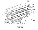
- FIG. 5 ais an exploded isometric view of a second embodiment of a PM machine according to the present invention, with the stator shown in ghost lines to reveal the winding detail therein;
- FIG. 5 bis an enlarged isometric view of a portion of the stator of the device of FIG. 5 a , with a portion broken away to reveal detail therein;
- FIG. 5 cis an enlarged cross-sectional partial view of the device of FIG. 5 a , schematically showing magnetic flux paths in the device;
- FIG. 6 bis an isometric view of the stator of the device of FIG. 6 a;
- FIG. 6 cis a rear isometric view of the stator of FIG. 6 b;
- FIG. 6 dis an enlarged isometric view of a portion of the rotor and stator of the device of FIG. 6 a , with a portion broken away to reveal detail therein;
- FIG. 6 fis a cross-sectional view along the lines 6 f — 6 f in FIG. 6 e;
- FIG. 7 ais an isometric schematic representation of a method for making primary windings in accordance with the present invention.
- FIG. 7 bis much-enlarged cross-section of a portion of a stator showing the windings of FIG. 7 a;
- FIG. 8 ais an enlarged isometric view and a cross-sectional view similar to FIGS. 6 d and 6 e , respectively, schematically representing electrical and magnetic activity on start up of the present invention
- FIG. 8 bis an enlarged isometric view and a cross-sectional view similar to FIG. 8 a , respectively, schematically representing electrical and magnetic activity immediately after the moment in time represented in FIG. 8 a;
- FIG. 9is a schematic of an equivalent electrical circuit of one phase the device of FIG. 6 a;
- FIG. 10is a schematic of an embodiment of a secondary winding control circuit
- FIGS. 11 a and 11 bare schematics of other examples of secondary winding control circuits
- FIG. 12 ais an enlarged isometric view and a cross-sectional view similar to FIGS. 6 d and 6 e , respectively, schematically representing electrical and magnetic activity of another embodiment of the present invention employing a low Curie point material;
- FIG. 12 bis an enlarged isometric view and a cross-sectional view similar to FIGS. 6 d and 6 e , respectively, schematically representing electrical and magnetic activity after the secondary winding fuse of the present invention blows;
- FIG. 13 ais an enlarged isometric cross-sectional view of a portion of the stator of another embodiment of the present invention.
- FIG. 13 bis an enlarged isometric cross-sectional view of a portion of the stator of an alternate design for the embodiment of FIG. 13 a;
- FIG. 14is a schematic of an aircraft accessory system employing a multi-channel version of the present invention.
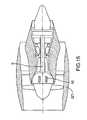
- FIG. 15shows a gas turbine engine incorporating the present invention, with a portion of the engine broken away to reveal a cross-section thereof.
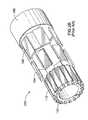
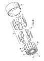
- PM machine 10has a rotor 12 which includes a plurality of permanent magnets 14 retained by a yoke 16 and retention sleeve portion 18 .
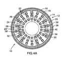
- Machine 10also has a stator 20 which includes at least a primary winding 22 and at least a secondary winding 24 (for clarity, only one of each such winding is shown), separated in this embodiment by a winding air gap 26 and disposed in radial slots 28 between a plurality of adjacent teeth 30 in a back iron 32 .
- a winding air gap 26for clarity, only one of each such winding is shown
- Stator 20also includes a core or “bridge” portion 40 bridging adjacent pairs of teeth 30 and passing between adjacent portions of primary winding 22 , as will be described in more detail below.
- the materials for PM machine 10may be any deemed suitable by the designer. Materials preferred by the inventor are: samarium cobalt permanent magnets, maraging steel (preferably 250 or 300) retention sleeve, aluminum yoke, copper primary and secondary windings, a suitable electromagnetic material for the stator teeth and for the back iron.
- primary winding 22 of the embodiment of FIG. 4 aconsists of a conductor which enters a first end 27 of a slot 28 a on a first side 40 ′ of bridge 40 , and a first leg portion 23 ′ of winding 22 travels down slot 28 a , an end turn portion 23 ′′ of winding 22 crosses bridge 40 at the second (i.e. other) end 29 of slot 28 a and a second leg portion 23 ′′′ travels back along slot 28 a and exits slot 28 a from the first end 27 , but on a second side 40 ′′ of bridge 40 (i.e. opposite to the first side 40 ′ the winding entered).
- Primary winding 22then continues along the first end 27 of the stator to the next appropriate slot 28 b and again enters from the first end 27 of slot 28 b , but preferably from the second side 40 ′′ of bridge 40 (i.e. the same side of bridge 40 as it exited the last slot 28 a ). Primary winding 22 then travels down slot 28 b , loops around bridge 40 at the second end 29 of slot 28 b , then proceeds back up slot 28 b and exits the first end 27 of slot 28 b , and is now again on the first side 40 ′ the bridge piece, and so on. Primary winding 22 is thus positioned in the desired slots 28 in stator 20 . This particular pattern both facilitates assembly (as will be discussed further below) and provides an orderly arrangement for primary winding 22 , and also beneficially assists winding separation within PM machine 10 see FIG. 7 b ).
- secondary winding 24 in the embodiment of FIGS. 4 a - 4 fis a shorted winding to provide a squirrel cage configuration. Secondary winding 24 thus has a plurality of legs 42 extending between end rings 44 .
- FIG. 4 ea close-up partial isometric section shows the relative arrangements of primary winding 22 and secondary winding 24 (only a portion of one primary winding 22 is shown for clarity).
- the interaction of magnets 14 and windings 22 , and windings 22 and 24creates magnetic flux within PM machine 10 .
- a primary magnetic flux path or magnetic circuit 46 and a secondary magnetic flux path or magnet circuit 48are set up within PM machine 10 , as are represented schematically in FIG. 4 e .
- the secondary magnetic flux pathis isolated from the rotor and rotor magnetic circuit.
- Primary magnetic circuit 46includes rotor 12 , rotor air gap 24 , bridge 40 and the portion of stator teeth 30 between rotor 12 and bridge 40 .
- Primary magnetic circuitencircles primary winding 22 and, in use (as described further below) either causes or is caused by a current flow in primary winding 22 , depending on whether machine 10 is operated as an alternator/generator or motor, respectively.
- Secondary magnetic circuit 48includes bridge 40 , back iron 32 and the portion of stator teeth 30 between back iron 32 and bridge 40 .
- Secondary magnetic circuitencircles secondary winding 24 .
- Secondary winding 24is provided for control purposes and preferably, therefore, not connected to an output circuit of machine 10 .
- stator 20 , bridge 40 and slot 28together define two slots or openings 28 ′ and 28 ′′, with one opening 28 ′ for the primary winding only, and another opening 28 ′′ for the primary and secondary windings.
- the primary magnetic circuitencircles opening 28 ′ while the secondary magnetic circuit encircles opening 28 ′′.
- the opening 28 ′is radially closer to the rotor than the other opening 28 ′′.
- bridge 40extends a portion of the distance from the radially innermost portion of slot 28 to the radially outermost portion of slot 28 to thereby define openings 28 ′ and 28 ′′.
- bridge 40also preferably extends the entire distance from stator faces 27 to 29 and thus is adjacent the primary winding 22 along the length of legs 22 a and 22 c .
- Leg 23 ′is preferably substantially parallel to winding 24 along its leg 25 ′ extending the length of opening 28 ′′.
- FIGS. 5 a - 5 ca second “inside rotor” embodiment of the present invention is shown.
- the same reference numeralsare used to denote the analogous elements described with reference to FIGS. 4 a - 4 d .
- the skilled readerwill also appreciate the relative similarities and differences in construction and operation of typical “outside” vs. “inside” rotor configurations, and thus these will not be discussed further here. Aspects of the second embodiment not specifically described below may otherwise be assumed to be made in accordance with the description of the analogous element described above.
- the second embodiment of the present inventionis another multi-winding, multi-phase configuration.
- there are multiple primary windings 22 and secondary windings 24preferably one for each phase.
- primary windings 22 and secondary windings 24preferably one for each phase.
- secondary windings 24preferably one for each phase.
- only one phaseis depicted. Though only the windings of one phase will be described below, preferably the description will apply to the windings of all phases.
- each phase of primary winding 22consists of a conductor which, in a manner similar to that described above, enters a first end 27 of a slot 28 a on a first side 40 ′ of bridge 40 , travels down slot 28 a , crosses bridge 40 at the second (i.e. other) end 29 of slot 28 a and travels back along slot 28 a and exits slot 28 a from the first end 27 , but on a second side 40 ′′ of bridge 40 (i.e. opposite to the first side the winding entered).
- Primary winding 22then continues along the first end 27 of the stator to the next appropriate slot 28 b and again enters from the first end 27 of slot 28 b , but preferably from the second side 40 ′′ of bridge 40 (i.e. the same side of bridge 40 as it exited the last slot 28 a ). Primary winding 22 then travels down slot 28 b , loops around bridge 40 at the second end 29 of slot 28 b , then proceeds back up slot 28 b and exits the first end 27 of slot 28 b , and is now again on the first side 40 ′ the bridge piece, and so on. Primary winding 22 is thus positioned in the desired slots 28 in stator 20 .
- each phase of secondary winding 24consists of a conductor which enters one end 27 of the slot 28 a occupied by the primary winding 22 of that phase and then exits slot 28 s from the opposite end 29 and continues to the next appropriate slot 28 b (preferably the next slot occupied by this phase of primary winding 22 , as depicted in FIG. 5 a ), and so on.
- FIG. 5 bthe relative arrangements of primary winding 22 , secondary winding 24 and bridge 40 can be seen within stator 20 .
- FIG. 5 ca schematic representation of the primary and secondary magnetic circuits flux paths 46 and 48 , respectively, is shown when PM machine 10 is in use.
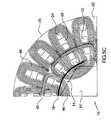
- FIGS. 6 a - 6 fA third embodiment of the present invention is disclosed in FIGS. 6 a - 6 f .
- this embodimentis an outside-rotor, 3-phase, dual “channel” PM machine, depicted with one set (i.e. “channel”) of primary windings 22 absent (for clarity), as will be described in more detail below.
- the same reference numeralsare used in FIGS. 6 a - 6 f to denote the analogous elements described with reference to the embodiments above, and thus these elements will not be redundantly described here but rather addressed only as required. Aspects of the third embodiment which are not specifically described below may be assumed therefore to be otherwise made in accordance with the description of the analogous elements above.
- stator 20 of PM machine 10is conceptually divided into an “a” half and a “b” half, and thus windings 22 and 24 will be described in terms of primary windings “ 22 a ” and “ 22 b ” and secondary windings “ 24 a ” and “ 24 b ”.
- Other features associated with windings 22 and 24may also be described as “a” or “b” specific.
- Primary windings 22 bare not depicted in FIGS. 6 a - 6 c for clarity, but may be assumed to be otherwise identical to primary windings 22 a.
- each primary winding 22 ais provided with its own primary terminal 50 a (see FIG. 6 b ) for ease of connection to an associated primary circuit (not shown).
- Secondary windings 24 a and 24 beach have squirrel cage-type arrangement (i.e. with legs 42 and end rings 44 ) and have secondary terminals 52 a and 5 b , respectively, for ease of connection to an associated secondary circuit. Referring to FIGS.
- each leg 42 of secondary windings 24includes a current-limiting device such as a fuse or breaker element 54 .
- Stator 20has a plurality of passages 58 defined on its inner periphery to act as an oil transfer mechanism, as will also be described in more detail below.
- preferably paper spacers 56are placed between primary windings 22 and stator 20 , and between secondary winding 24 and stator 20 , for insulation purposes.
- Bridges 40are preferably non-integral with stator 20 , and thus inserted as an assembly as depicted schematically in FIG. 6 c , which advantageously permits the designer to select different materials for bridge 40 and stator 20 .
- a bridge materialmay be chosen to alter the magnetic or performance characteristics of machine 10 , as will be discussed in greater detail below.
- Non-integral bridges 40may also beneficially facilitate machine assembly, as explained further below.
- this embodimenthas a “multi-channel” architecture, in that a plurality of fully independent “sets” of primary and secondary windings are provided.
- two such setsare provided (i.e. sets “a” and “b” described briefly above), namely primary windings 22 a and 22 b (primary winding 22 b is not shown, for clarity) and secondary windings 24 a and 22 b .
- This multi-channel architecturepermits a plurality of motor/alternators to exist within the same stator, and which may either be operated conjunctively, or independently, as desired.
- the outputs of the winding setsmay be combined to provide a single output, but in the event of a fault which requires one winding set to be shut down, the remaining winding set(s) may continue operation unaffected.
- This featurethus permits more than one motor/generator to exist within the same machine (as is discussed in greater detail below), thereby providing redundancy which may very valuable in applications where a complete shutdown would be catastrophic.
- Stator 20has a tooth gap 36 preferably provided in accordance with the applicant's co-pending application Ser. No. 10/393,252, filed Mar. 21, 2003, the contents of which are incorporated into this disclosure by reference.
- tooth gap 36is not necessary in the stator face adjacent the rotor (i.e. near 28 a , as in FIG. 4 e ), but rather slots 28 may open to the opposing face (i.e. the face opposing the stator's ‘rotor face’—i.e. nearer to 28 b in FIG. 4 e ) or slots 28 may have no such openings adjacent either 28 a or 28 b , but rather having openings only at faces 27 and 29 .
- Primary windings 22 and secondary winding 24are preferably each composed of single conductor provided in a single turn configuration. This single conductor, single turn configuration is preferred because it reduces the probability of a short circuit within the winding.
- Primary windings 22are preferably stamped or otherwise provided from sheet metal and then pre-bent into a desired shape prior to insertion into the stator. An example series of fabrication steps are shown schematically in FIG. 7 a .
- bridge 40may be inserted into the windings before insertion into the stator, and this removable bridge portion and stator architecture permits the windings to be completely pre-assembled before being inserted into the stator, thereby improving manufacturability.
- primary windings 22are also preferably installed in stator 20 such that they are individually radially separated from one another to provide increased anti-short circuit protection between adjacent windings.
- primary windings 22may be “pre-wrapped” around bridges 40 prior to assembly into teeth 30 of stator 20 .
- primary winding 22enters and exits slot 28 of stator 20 between from the same side, as described above.
- This design featureadvantageously permits primary windings 22 to be pre-assembled with bridges 40 (and spacers 56 , as desired) prior to insertion into slots 28 of stator 20 . This permits traditional winding machines (and their associated manufacturing and tolerance difficulties) to be avoided altogether in the present design.
- a primary flux path 46in use, whether in a motor or alternator mode, the interaction of magnets and primary winding 22 causes a primary flux path 46 to be set up which runs down a first portion (i.e. the upper end) of tooth 30 , across bridge 40 , and back up a corresponding first portion of an adjacent tooth 30 , and then to and through the rotor to complete the loop, as depicted by the solid arrows in FIG. 8 a .
- This primary flux pathcauses (or is the result of, depending on whether PM machine is operated as a motor or an alternator) current to pass through primary winding 22 (in a closed primary circuit).
- this current flow through primary winding 22causes a secondary flux path 48 to be set up through a second portion (i.e. the lower end) of teeth 30 , through back iron 32 , back up through the corresponding second portion of an adjacent tooth 30 and then back through bridge 40 to close the secondary loop.
- This secondary magnetic circuitcauses a secondary current to flow through secondary winding 24 (in a closed secondary circuit)
- the magnetic flux in secondary path 48thus loops the portion of secondary winding 24 opposite primary flux path 46 , and the interaction of primary winding 22 and secondary winding 24 thus sets up a secondary magnetic circuit in machine 10 . It can clearly be seen, therefore, that the magnetic flux path(s) of the present invention are entirely different than is present in a typical prior art PM machine. As will be described in greater detail below, these characteristics of the present invention present many advantages to a PM machine designer.
- a PM machineWhen used as an alternator, a PM machine will generate voltage and current which may be used as required, or stored for later use. Often, a conditioning step of some description is required to convert the raw output of the alternator into a more useful form (typically by varying the voltage, current and/or frequency and perhaps also rectify the output into DC current).
- ISGgas turbine integral-starter generator
- in normal operation in an alternator modevariations in engine speed and load results in an ISG output current and voltage which requires conditioning before the generated electricity is useable by on-board aircraft systems such as electric oil pumps, fuel pumps and other accessories. Therefore, means may be provided outside PM machine 10 to control and condition the machine output (i.e. preferably the output of primary winding 22 ).
- the present inventionwhen operated as an alternator, the present invention also permits the output the primary winding(s) 22 to be controlled to a certain extent through a manipulation of at least the current secondary winding(s) 24 , as will now be described.
- the present inventionset ups a transformer-type relationship between primary winding 22 and secondary winding 24 , as is schematically represented FIG. 9 by an simple equivalent circuit.
- the equivalent “transformer”is a 1:1 transformer, i.e. the number of turns in primary winding 22 equals the number of turns in secondary winding 24 (here, each has only one turn).
- I PRIMARY *V PRIMARYI SECONDARY *V SECONDARY
- the magnetic flux developed within secondary magnetic circuitis proportional to the current flow in primary winding(s) 22 and inversely proportional to the magnetic coupling within secondary magnetic circuit.
- the magnetic flux in secondary magnetic circuitis proportional to the magnetic coupling, and inversely proportional to the current flow in secondary winding 24 (i.e. the current induced in the secondary winding causes the secondary flux to be cancelled). Therefore, the current flowing in secondary winding 24 directly influences the current generated in the primary winding 22 by the rotating magnetic system of PM machine 10 , and the current flow is a function of the current flow in the primary windings.
- the secondary windings 24are inductively coupled only to the primary winding 24 (excluding leakage, etc.), and thus the secondary winding 24 and secondary magnetic circuit 48 are only influenced by the flux in the primary magnetic circuit 46 set up by the primary winding 24 (except in the case of a low Curie point bridge, of the type describe further below, when the bridge is at or exceeds the bridge material's Curie point temperature).
- This aspect of the present inventionpermits the designer to use the secondary winding to manipulate the output of primary winding 22 , and thus secondary winding 24 may be used as a source of control PM machine 10 .
- Means for controlling the operation of PM machineare thus available within the machine itself, as the “control” current may be generated within PM machine 10 , that is in secondary winding 24 . In some instances, therefore, no external source of control current may be required.
- the novel architecture of the present inventiontherefore lends itself to many novel possibilities for control systems for the machine, a few examples of which will now described.
- the output (i.e. from a primary winding 22 ) of PM machine 10 in an alternator modemay be controlled by mechanical means by directly influencing the current in the secondary winding 24 .
- a current limiting device 54such as a fuse element, is preferably provided in one or more legs 42 (preferably all legs) of secondary winding 24 .
- current in secondary winding 24is a function of current in the primary winding 22 .
- current in the primary windingrises (such as in the case of an internal fault such as a short circuit) so, too, will the current in the secondary winding.
- a fuse element 54in use, when the current in secondary winding 24 exceeds a certain threshold, a fuse element 54 would “blow”, thereby creating an open-circuit in secondary winding (i.e. no secondary current) and, by reason of the electrical inter-relationship between the primary and secondary circuits, the output current of primary circuit will be limited.
- the flux in primary magnetic circuit 46induces in a significant flux in secondary magnetic circuit 48 . Consequently inductive reactance is increased, which can be used limit maximum output current to a maximum synchronous impedance of machine 10 . (Prior to opening of the fuse, when secondary current is allowed to flow in the secondary winding, the resulting secondary flux is in the opposing direction and thus tends to cancel the secondary flux.
- machine 10is relatively unaffected by the presence of the secondary until the secondary circuit opens.) This permits the control of the machine's impedance and offers PM machine 10 intrinsic thermal protection against a short-circuit in primary winding 22 when operating in an alternator mode. Any suitable fuse may be used.
- secondary winding 24Prior to opening of fuse 54 (i.e. in normal machine operation), secondary winding 24 as disclosed in the embodiment of FIGS. 6 a - 6 f operates in a simple short-circuited squirrel cage arrangement, and thus will have no perceptible effect on primary winding 22 . In other words, when secondary winding 24 is fully short circuited, PM machine 10 maybe operated in a manner substantially in similar to prior art machines.
- current in the secondary winding 24can be influenced by electronic means to control the current in primary winding 22 .
- Direct electronic control of current in secondary winding 24can be achieved by an impedance or other control system, such as the examples depicted in FIGS. 10 , 11 a and 11 b which provide proportional type or other control adjustments of the current in secondary winding 24 , to thereby control the current in primary winding 22 .
- FIG. 10shows an example of a simple arrangement for solid state secondary winding electronic control circuit 60 for control secondary winding 24 for machine 10 .
- the main elementsare D 1 Bridge rectifier, and Q 1 IGBT device (Insulated Gate Bipolar Transistor).
- the device Q 1could also be substituted by another type of device, such as a power MOSFET or other switching device.
- multiple secondary windings 24 1 , 24 2 , 24 3preferably each have similar circuits, e.g. as 60 is depicted in FIG. 10 , which could be controlled by a single control system.
- V S1the control voltage
- V S1the control voltage
- switch Q 1 ‘on’ or ‘off’the control voltage
- secondary winding 24preferably has multiple turns (relative to primary winding 22 ) such that the current being switched by the Q 1 device would be stepped-down to only a fraction of the current flow in primary main winding 22 to thereby permit low current control circuitry connected to secondary winding 24 to control a high current machine output from primary winding 22 .
- the switched voltage at Q 1would generally still be higher than the primary machine voltage, but it will be understood that this is still practical since Q 1 devices are available which operate at over 1500V).
- This control arrangementis useful as a voltage regulator when the output of machine 10 (i.e. the output of primary winding 22 ) is to be rectified for use as a DC supply or further conditioned as desired.
- the current induced in the secondaryis affected and controlled by the elements in the secondary circuit, and this control permits the current and/or voltage of the primary to be affected as desired to control the operation and behaviour of PM machine 10 .
- FIG. 11 aa different secondary winding electronic control circuit 60 is shown, in which the output of secondary winding 24 fed in parallel through parallel diode 62 and transistor 64 pairs (in this case the transistors are NJFETs) to permit the secondary current to be modulated to thus control the primary winding 22 output.
- FIG. 11 ba second embodiment of a secondary winding control circuit 70 is shown, in which the output of secondary winding 24 fed to a thermally-sensitive switch 72 . Still other control schemes are possible, as will be appreciated by one skilled in the art upon consideration of this disclosure.
- the current in secondary winding 24can be influenced by varying the magnetic coupling in the secondary magnetic circuit to thereby control the primary winding current.
- the configuration and material selection for components such as stator teeth 30 , back iron 32 and bridge 40will also vary the magnetic properties of the secondary magnetic circuit, thus permitting the designer to “control” the performance of PM machine 10 .
- the secondary magnetic circuitincludes a low Curie point material such as ferrite, when the machine operates with the secondary magnetic circuit at or above the Curie temperature the effect or influence of the secondary winding would be greatly reduced.
- non-integral bridge pieces 40may provide benefits for the assembly of PM machine 10 .
- the provision of a non-integral bridgepermits the designer to select a different material for bridge 40 .
- additional short-circuit controlcan be provided to PM machine 10 in accordance with the teachings of the applicant's U.S. Pat. No. 6,313,560 (the '560 patent), the contents of which are incorporated by reference into this disclosure.
- the '560 patentteaches that materials with a low Curie temperature (referred to as low Curie point materials in this description), such as ferrite, can be beneficially used in electric machines to provide thermal protection in the event that a fault causes normal operating temperatures to be exceeded. This concept may also be applied in the present invention, as will now be described.
- bridges 40are made of different material than teeth 30 , which thereby permits the designer to alter the behaviour of the primary and secondary magnetic circuits.
- bridge 40is made of a low Curie point material of the type described in the '560 patent, such as ferrite.
- primary winding 22is preferably closely thermally coupled to bridge 40 pieces to permit a fast and effective control of the machine in the fault condition.
- bridge 40In the event of a fault that raises the temperature of a bridge 40 to or above the Curie point of the ferrite bridge material, bridge 40 begins to lose its ability to conduct magnetic flux, and thus (eventually, as temperature increases) becomes “invisible” to the magnetic circuit in stator 30 .
- the primary and secondary magnet circuitsare thus joined into one circuit (reference 47 ), as magnetic flux (eventually) no longer crosses bridge 40 , or flux is at least greatly reduced.
- the low Curie point materialis selected such that when the Curie point of bridge 40 is reached, bridge 40 doesn't completely stop magnetic flux from passing therethrough (and thus doesn't completely “shut down” the primary current down, but rather as the Curie point is reached and exceeded, the amount of magnet flux passing though the bridge is progressively reduced, thereby acting just to “turn down” the primary current, rather than shut it off completely.
- the amount the current is “turned down” by bridge 40is controlled by the amount of magnetic “short circuit” experienced as a result of reaching the bridge material Curie temperature, and is thus affected not only by bridge 40 material, but also by (a) tooth pitch, (b) back iron thickness, (c) tooth length, and (d) back iron material, among other things. The designer may use this knowledge to control the “turn down” behaviour of PM machine 10 in the event a machine fault occurs.
- a close thermal coupling between the windings and the low Curie point material of bridge 40is advantageous and thus preferred. This close coupling may be achieved by close contact between primary winding 22 and bridge 40 , and/or may be enhanced by the use of bonding material between the windings and the low Curie point material.
- the use of a low Curie point bridge materialcan provide thermal protection to PM machine 10 in fault situations where the current in secondary winding 24 is not high enough, for example, to blow a fuse 54 and yet continued operation of machine 10 could result in damage to the machine.
- the use of a low Curie point material in conjunction with the present inventioncan permit intrinsically redundant safety systems to be incorporated.
- PM machine 10Another significant advantage of PM machine 10 is that, when a low Curie point material is employed as described, if the internal fault is a short in a loop (or loops) of the winding, the described low Curie point embodiment can permit only the faulty loop(s) to be shut down or turned down, leaving the operation of the rest of the winding essentially unaffected.
- a low Curie point materialmay also be used in the secondary circuit for control purposes.
- a low Curie point materialsuch as ferrite
- the designcould permit the current in the primary circuit to be increased as the low Curie point material in the secondary circuit is heated above its Curie temperature.
- Thismay be a beneficial feature, depending on the performance criteria or specification for a particular application for PM machine 10 .
- this featuremay be used to increase output to a cooling system such that the machine, operated as an alternator, both provides cooling power and controls temperature.
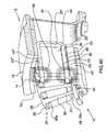
- the present inventionmay be provided including a cooling system including a coolant 80 (preferably oil) within PM machine 10 .
- Oilis circulated through passages 58 inside a stator jacket 82 around and along the primary and secondary windings to assist in cooling them.
- an oil jet 84 in an insert 86directs oil onto the end turn of the primary winding. If the insert 86 is made of aluminum or copper, the stray inductance of the end turn is also reduced, thereby reducing the overall machine impedance.
- control schemessuch as those disclosed above may be employed individually or may be combined as desired to permit several control features to exist contemporaneously within the PM machine.
- prior art fixed-geometry PM machinestypically are not controllable in any way other than by the speed at which they are operated, this controllability feature of the present invention is of significant value to the PM machine designer, particularly in those applications where the rotational speed of the machine cannot itself be used to control machine output.
- the present inventionalso offers a robust and reliable design suitable for aerospace applications.
- the present inventionprovides a type of internal current-limiting transformer (in the described embodiments, a 1:1 transformer, but other ratios are possible) built into the magnetic structure of the machine.
- the “primary”is connected electrically in series with the main output feeders of the alternator, and the “secondary” is configured preferably as a short circuit, which will become an open circuit, by means of a fuse, or other circuit interrupting or current limiting means, above a certain pre-selected temperature.
- the pre-selected threshold temperaturewill be the maximum safe sustained operating temperature of the machine, above which the machine is susceptible to thermal damage (e.g., say about 300° C. when typical electric machine construction materials are used).
- the secondaryWhen the secondary becomes open circuit, current flow in the primary is significantly reduced as a result of the inductive reactance of the “transformer” under no load conditions, which thereby results in an increase in the machine impedance.
- the increase in machine impedanceis a significant one (e.g. doubling the machine impedance), such that the short circuit current in the primary is effectively limited to a value equal to the maximum power rating of the machine.
- the advantage of using this “transformer” type arrangementis that each stator slot may be protected by its own “transformer-breaker”, and thus the voltage that is being fused is only a fraction (e.g. 1 ⁇ 6 th in a dual-channel 3 phase machine of the type described further below) of the total generated voltage. Consequently, the breaker/fuse in the secondary will be less likely to experience an arc when the circuit is opened.
- the ‘transformer’ of the present inventionmay also be remote from the stator, such that a portion of the primary and some or all of the secondary are disposed external to the stator.
- the net effect of the low Curie point embodiment described aboveis that two thermal protection schemes may be implemented in the machine, namely (1) a low Curie point type over-temperature protection scheme, which provides intrinsic and automatic reversible (i.e. non-permanent) overload protection to prevent permanent damage to the machine for moderate to severe temperature overloads, and (2) a high temperature protection scheme which will automatically react in the event that (i) the first-mentioned mechanism does not sufficiently control the short circuit current within the time desired, and/or (ii) in situations where the short circuit resistance(s) in the machine is (are) very low.
- a low Curie point type over-temperature protection schemewhich provides intrinsic and automatic reversible (i.e. non-permanent) overload protection to prevent permanent damage to the machine for moderate to severe temperature overloads
- a high temperature protection schemewhich will automatically react in the event that (i) the first-mentioned mechanism does not sufficiently control the short circuit current within the time desired, and/or (ii) in situations where the short circuit resistance(s)
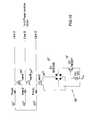
- a PM machine 10 of the type described with reference to FIGS. 6 a - 6 f abovein essence provides a single rotor rotating relative to multiple (in the described case, two) independent stators.
- rotor 12rotates relative to a “virtual” stator 20 a (the portion with primary windings 22 a ) and also relative to a “virtual” stator 20 b (the portion with primary windings 22 b ).
- PM machineis “two-in-one machine in this case.
- PM machine 10is then preferably connected to fully redundant accessory systems, which may include redundant power conditioning units (PCU) 90 , oil pumps 92 , fuel pumps 94 , hydraulic pumps 96 and other electrically-run accessories 98 .
- PCUredundant power conditioning units
- this dual- or multi-channel designpermits a fully redundant system (system A+system B, in FIG. 14 ) to provided with a minimum of hardware, thereby minimizing weight and space and increasing reliability.
- generator efficiencyis proportional to I 2 losses, it is often preferable to run two “machines” like this, each at 1 ⁇ 2 of the output current, rather than one machine a full output current.
- power from the two “machines”may be shared, if desired, between the PCUs with the appropriate connections, etc., to permit redundancy in the case of a “machine” or PCU failure.
- the present inventionis particularly well suited, among other things, to prevent overheating problems of an internally short circuited permanent magnet arrangement that is driven continuously, such as in the case of an internal fault in a machine 10 driven by a shaft ‘S’ in gas turbine engine ‘GT’, as depicted in FIG. 15 .
- the inventionalso permits a certain level of control to be attained over an alternator which is driven at variable speeds (i.e. driven by an operating propulsive aircraft gas turbine).
- the machinemay be single or multi-phase, single or multi-channel.
- the windingsmay have single or multi turns per slot, the number of turns of primary windings does not have to equal the number of turns of secondary winding, the number of turns of a winding not necessarily have to be a whole number, the number of primary windings does not have to equal the number of secondary windings, as one or more windings in a slot may perhaps be present in a slot.
- winding typesmay be used (squirrel cage, lap, etc.), and the windings may be any conductor(s) (i.e. single conductor, more than one wire, insulated, laminated, etc.) or may be superconductors.
- multiphase machinethere may be zigzag, delta, or Y-connected windings in accordance with known techniques. There need not be an air gap between the primary and secondary winding, as long as the windings are electrically isolated from one another.
- the rotorcan be electromagnetic (i.e. permanent magnet not necessary), and may be provided in an outside or inside configuration, or any other suitable configuration.
- the bridgemay be provided in one or more slots, and may be integral or non-integral with the rest of the stator.
- a secondary bridgemay also be provided, in the form of the back iron, for example, if the secondary winding(s) are wound around the back iron. Other secondary bridge configurations are also possible.
- Secondary windingmay also be used for control purposes in motor mode.
- Other portions of the stator and rotor, such as back iron for example,may be provided of a low Curie point material to achieve the benefits of the present invention.
- Still other modifications which fall within the scope of the present inventionwill be apparent to those skilled in the art, in light of a review of this disclosure, and such modifications are intended to fall within the equivalents accorded to the appended claims.
- the term ‘alternator’is used generically to mean a device used for creating electricity, and is not intended therefore to be limited to a device for generating an output alternating current.
Landscapes
- Engineering & Computer Science (AREA)
- Power Engineering (AREA)
- Windings For Motors And Generators (AREA)
- Permanent Magnet Type Synchronous Machine (AREA)
- Iron Core Of Rotating Electric Machines (AREA)
Abstract
Description
The invention relates to electric machines such as alternators and motors and, more particularly, to a novel architecture for such machines.
Referring toFIG. 1 , a typical permanent magnet (PM) machine according to the prior art is shown at100. Priorart PM machine 100 has arotor 102, withpermanent magnets 104 mounted thereto by aretaining ring 106, which is mounted on arotatable shaft 108.Rotor 102 is adjacent astator 110 having a plurality ofwindings 112 interspersed between a plurality ofteeth 114 mounted to aback iron 116. (For ease of illustration, the adjacent elements ofwindings 112 inFIG. 1 bare shown unconnected.) As is well understood,PM machine 100 may operate in a generator/alternator mode or a motor mode. When operated in a generator/alternator mode, an external torque source forces rotation of the shaft (and thus the rotor and the magnets), and the interaction of the magnets and the windings causes a magnetic flux to loop the windings in the slots. As the rotor rotates, the magnetic flux in the stator structure changes, and this changing flux results in generation of voltage in the windings, which results in an output current that can be used to power electrical devices, or be stored for later use. When operated in a motor mode, a voltage from an external source is applied to the stator windings which causes current flow in the windings and results in a magnetic flux to be set up in the magnetic circuit formed by the teeth and back iron. When current is supplied in an appropriate manner to the windings, the rotor can be made to rotate and thus produce usable torque. The operation of such machines is thus well understood.
Such PM machines can have an “inside rotor” configuration as shown inFIGS. 1 aand1b, or an “outside rotor” configuration as shown inFIGS. 2 aand2b. The reference numerals inFIGS. 2 aand2bcorrespond to the corresponding features described with reference toFIGS. 1 aand1b. In the “outside rotor” configuration, however,rotor yoke 108′ replacesrotor shaft 108. For ease of illustration, the adjacent elements of the windings inFIG. 2 bare also shown unconnected.
Irrespective of whether operated in an alternator or motor mode, the magnetic flux path in these prior art PM machines is as partially and simply depicted inFIG. 3 , the flux path as indicated by thearrows 118, and the poles and virtual poles denoted by an “N” or an “S”. It is thismagnetic flux 118 which induces a voltage in the alternator winding112 (or in the case of a motor, creates the magnetic attraction with thepermanent magnet 106 to cause rotor rotation), as described above.
Prior art PM machines (and particularly PM alternators) suffer from at least two limitations which has limited their usefulness somewhat, namely: (1) the output of the PM alternator may only be controlled within the machine (i.e. varied) by varying the rotor speed (assuming a fixed geometry machine), and (2) if a short circuit or other internal fault occurs in the machine, the internal fault current can become extremely destructive to the machine, particularly in high power applications. With reference to the first drawback, this intrinsic feature particularly limits the usefulness of a PM generator in circumstances where the rotor rotation speed cannot be independently controlled. It would therefore be desirable to improve the controllability of PM machines, generally.
PM machines offer certain attractive advantages for use in high speed applications, and particularly as an integrated starter-generator (ISG) for a propulsive or prime-mover gas turbine engine, in which the PM machine is mounted directly to a turbine shaft of the engine. This shaft, of course, is driven at whatever speed is required for the running of the gas turbine engine (typically anywhere in the range of 0-50,000 rpm) and thus the shaft speed cannot be varied to suit the controllability limitations of the PM machine, but rather is dictated by the mechanical output requirements of the engine. Therefore, although the ISG designer will know the average steady state speed of the turbine shaft at cruise, can thus design an PM alternator system to provide sufficient electrical output necessary to power the aircraft systems at cruise (where the engine typically spends most of its operation cycle), accommodations must be made for take-off (where the turbine shaft may be turning at twice cruise speed, doubling alternator output) and landing approach (where turbine shaft speed may half of cruise speed, halving alternator output). The problem is an order of magnitude greater for certain military applications, where cruise speed is rarely maintained for any length of time. The prior art therefore poses optimization problems to the ISG designer, where critical over-power and under-power scenarios must be managed to achieve a satisfactory design.
There are other drawbacks inherent prior art designs, which result in complicated mechanisms and fabrication techniques. U.S. Pat. No. 6,525,504 to Nygren et al. shows one example of a relatively complicated solution to the control of certain aspects of the operation of a PM machine used in high voltage power generator applications. The device offers only limited control over operation of the machine, and its complexity makes it unsuitable for higher reliability and lighter weight applications such as, for example, aircraft applications.
Accordingly, there is a need to provide an improved PM machine which addresses these and other limitations of the prior art, and it is an object of this invention to do so.
In one aspect, the present invention provides an electric machine operable as an alternator, the machine comprising a magnetic rotor mounted for rotation about an axis; a stator adjacent the rotor, the stator including a plurality of radial slots defined in the stator between pairs of teeth, and a bridge mounted to the stator in at least one of the slots and extending between a pair of said teeth defining the at least one slot, the bridge dividing the at least one slot into at least two slot portions; a first winding forming at least a portion of a first circuit, the first circuit adapted to deliver generated electricity from the machine, the first winding having a loop portion including at least a first leg and a second leg, the loop portion disposed in the at least one slot such that the first leg is disposed in a first one of said at least two slot portions and adjacent a first side of the bridge, and the second leg is disposed in a second of said at least two slot portions and adjacent a second side of the bridge, the first and second sides of the bridge opposing one another; and a second winding forming at least a portion of a second circuit, the second circuit electrically isolated from the first circuit, the second winding disposed in the stator adjacent the second leg of the first winding.
In another aspect, the invention provides an electric machine operable as an alternator, the machine comprising: a rotatable magnetic rotor; and a stator assembly mounted adjacent the rotor assembly, the stator assembly including a plurality of openings including a first opening and a second opening, the first and second openings being separated by a portion of the stator assembly, a first electrical winding electrically connected to a first circuit, the first circuit adapted to provide electricity output from the machine when the machine is operated as an alternator, the first electrical winding disposed at least partially in the first opening and at least partially in the second opening so as to at least partially form a loop, and a second electrical winding connected to a second circuit, the second electrical winding electrically isolated from the first electrical winding, the second winding disposed in the second opening adjacent the first winding, wherein said portion of the stator assembly defines a portion of at least two magnetic circuit paths in the stator assembly for guiding magnetic flux generated as a result of the rotor rotating about the stator, and wherein a first one of said at least two magnetic circuit paths at least partially encircles the first opening and first winding therein, and wherein a second one of said at least two magnetic circuits at least partially encircles the second opening and the first and second windings therein, and wherein the secondary magnetic circuit is defined entirely within the stator assembly.
In another aspect, the invention provides a machine operable as an alternator, the machine comprising: a rotatable rotor; at least a first winding electrically connected to a machine output adapted to deliver generated output electricity from the machine when the machine is operated as an alternator; at least a second winding including a current-limiting device, the second winding electrically isolated from the first; and a stator adjacent the rotor, the stator defining at least a first opening and a second opening, the first winding disposed in the first opening and second opening, the second winding disposed only in the second opening, the stator and rotor together defining a primary magnetic circuit path around the first opening, whereby relative movement between the rotor and the stator causes a primary magnetic flux to flow around the primary magnetic circuit path which thereby induces a voltage across the first winding and an associated current flow in the first winding, the stator also defining a secondary magnetic circuit within the stator around the second opening, the first and second windings being disposed in the first and second openings and the first and second openings being positioned in the stator such that, in use, said voltage and current induced in the first winding induces a secondary voltage and an associated current flow in the second winding, wherein the current-limiting device is adapted to prevent a current flow in the secondary winding when a pre-selected threshold current in the secondary winding is exceeded, the second winding thereby limiting a maximum current flow in the first winding to at least a desired maximum current flow limit.
In another aspect, the invention provides a machine operable as an alternator, the machine comprising: a rotor having a plurality of magnetic poles; a first winding electrically connected to a machine output, the output adapted to deliver generated output electricity from the machine; a second winding including a current-limiting device; and a stator adjacent the rotor, the first and second windings disposed in the stator, the stator and rotor together defining a first magnetic circuit around a portion of the first winding, the stator defining a second magnetic circuit within the stator around a portion of the first and second windings, wherein the first and second windings are inductively coupled such that, in use, a voltage and current induced in the first winding by rotation of the rotor induces a secondary voltage and a current flow in the second winding, and wherein when a pre-selected threshold current is exceeded in the second winding, the current-limiting device prevents current flowing through the secondary winding, thereby limiting a maximum current flow in the first winding.
In another aspect, the invention provides a permanent magnet machine operable as an alternator, the machine comprising: a rotor having a plurality of permanent magnetic poles; a stator adjacent the rotor, the stator including at least a first winding disposed in at least one slot in the stator and a transformer disposed in the stator, the first winding inductively coupled to the rotor such that rotation of the rotor induces an output voltage and current in the first winding, the transformer electrically connected to the first winding and adapted to control at least one of said output voltage and current of the first winding.
In another aspect, the invention provides an electric machine operable as an alternator, the machine comprising: a stator; a magnetic rotor opposing the stator; and at least two windings disposed in the stator and electrically isolated from one another, wherein a first of the at least two windings comprises a primary winding in the stator for at least one of producing and consuming power, and wherein rotation of the rotor induces an output voltage and current in the primary winding, and wherein a second of the at least two windings comprises a secondary winding in the stator, the secondary winding being arranged and disposed in the stator adjacent a portion of the primary winding such that said induced current in the primary winding induces at least a voltage across the secondary winding, and wherein the secondary winding is inductively coupled substantially only to the primary winding and is inductively isolated from the rotor, and wherein the electric machine further includes means for controlling current flow in the secondary winding, said means adapted to thereby affect current flow in the primary winding.
In another aspect, the invention provides an electric machine operable as an alternator, the machine comprising: a rotor having a plurality of magnetic poles; a stator adjacent the rotor, the stator having an electromagnetic core portion defining a plurality of radially extending teeth, at least one bridge portion extending between two adjacent teeth, a first winding wound around the core and wound around the at least one bridge portion, and a second winding electrically isolated from the first winding and disposed in the stator adjacent the first winding, the second winding wrapped around the core portion but disposed remote from the bridge portion.
In another aspect, the invention provides a method of controlling an alternator, the alternator having a stator having at least one core portion extending between a plurality of radial teeth, a first winding wound around the at least one core portion and a second winding adjacent a portion of the first winding, the first and second windings electrically isolated from one another, the method comprising the steps of rotating the rotor to induce primary current, the primary current thereby inducing a secondary current in the second winding, and controlling the current flow in the second winding to thereby limit the maximum current in the first winding.
In another aspect, the invention provides a method of controlling a permanent magnet alternator, the alternator having a rotor, stator and at least one winding in the stator adapted to conduct an output current induced in the winding by rotation of the rotor, the method comprising the steps of: providing secondary winding electrically isolated from the at least one winding; placing the secondary winding adjacent a portion of the at least one winding; inductively coupling the secondary winding to the at least one winding and inductively isolating the secondary winding from the rotor, such that in use the at least one winding induces at least a voltage in the secondary winding; and using the secondary winding to control at least one of the voltage and current of the at least one winding.
Still other inventions are disclosed in this specification and attached figures, as well.
The patent or application file contains at least one drawing executed in color. Copies of this patent or patent application publication with color drawing(s) will be provided by the U.S. Patent and Trademark Office upon request and payment of the necessary fee.
For a better understanding of the present invention and to show more clearly how it may be carried into effect, reference will now be made by way of example to the accompanying drawings, showing articles made according to preferred embodiments of the present invention, in which:
A permanent magnet (PM) machine according to the present invention is depicted in at10 inFIGS. 4 ato4f. Referring first toFIGS. 4 aand4b,PM machine 10 has arotor 12 which includes a plurality ofpermanent magnets 14 retained by ayoke 16 andretention sleeve portion 18.Machine 10 also has astator 20 which includes at least a primary winding22 and at least a secondary winding24 (for clarity, only one of each such winding is shown), separated in this embodiment by a windingair gap 26 and disposed inradial slots 28 between a plurality ofadjacent teeth 30 in aback iron 32. (For ease of illustration inFIG. 4 b, the adjacent elements of secondary winding24 are shown unconnected.) The winding air gap serves as insulation and may be replaced by other suitable insulation. Arotor air gap 34separates rotor 12 andstator 20 in a typical fashion, and astator tooth gap 36 separatesadjacent teeth 30 at arotor interface surface 38 ofstator 20. Primary winding22 and secondary winding24 are thus electrically isolated from one another.Stator 20 also includes a core or “bridge”portion 40 bridging adjacent pairs ofteeth 30 and passing between adjacent portions of primary winding22, as will be described in more detail below.
The materials forPM machine 10 may be any deemed suitable by the designer. Materials preferred by the inventor are: samarium cobalt permanent magnets, maraging steel (preferably 250 or 300) retention sleeve, aluminum yoke, copper primary and secondary windings, a suitable electromagnetic material for the stator teeth and for the back iron.
Referring toFIGS. 4 cand4e, primary winding22 of the embodiment ofFIG. 4 aconsists of a conductor which enters afirst end 27 of aslot 28aon afirst side 40′ ofbridge 40, and afirst leg portion 23′ of winding22 travels downslot 28a, anend turn portion 23″ of winding22crosses bridge 40 at the second (i.e. other) end29 ofslot 28aand asecond leg portion 23′″ travels back alongslot 28aand exitsslot 28afrom thefirst end 27, but on asecond side 40″ of bridge40 (i.e. opposite to thefirst side 40′ the winding entered). Primary winding22 then continues along thefirst end 27 of the stator to the next appropriate slot28band again enters from thefirst end 27 of slot28b, but preferably from thesecond side 40″ of bridge40 (i.e. the same side ofbridge 40 as it exited thelast slot 28a). Primary winding22 then travels down slot28b, loops aroundbridge 40 at thesecond end 29 of slot28b, then proceeds back up slot28band exits thefirst end 27 of slot28b, and is now again on thefirst side 40′ the bridge piece, and so on. Primary winding22 is thus positioned in the desiredslots 28 instator 20. This particular pattern both facilitates assembly (as will be discussed further below) and provides an orderly arrangement for primary winding22, and also beneficially assists winding separation withinPM machine 10 seeFIG. 7 b).
Referring toFIG. 4 d, secondary winding24 in the embodiment ofFIGS. 4 a-4fis a shorted winding to provide a squirrel cage configuration. Secondary winding24 thus has a plurality oflegs 42 extending between end rings44.
Referring toFIG. 4 e, a close-up partial isometric section shows the relative arrangements of primary winding22 and secondary winding24 (only a portion of one primary winding22 is shown for clarity). In operation, as will be described in greater detail below, the interaction ofmagnets 14 andwindings 22, andwindings PM machine 10. Referring toFIG. 4 e, a primary magnetic flux path ormagnetic circuit 46 and a secondary magnetic flux path ormagnet circuit 48 are set up withinPM machine 10, as are represented schematically inFIG. 4 e. The secondary magnetic flux path is isolated from the rotor and rotor magnetic circuit.
Primarymagnetic circuit 46 includesrotor 12,rotor air gap 24,bridge 40 and the portion ofstator teeth 30 betweenrotor 12 andbridge 40. Primary magnetic circuit encircles primary winding22 and, in use (as described further below) either causes or is caused by a current flow in primary winding22, depending on whethermachine 10 is operated as an alternator/generator or motor, respectively. Secondarymagnetic circuit 48 includesbridge 40, backiron 32 and the portion ofstator teeth 30 betweenback iron 32 andbridge 40. Secondary magnetic circuit encircles secondary winding24. Secondary winding24, as will be described further below, is provided for control purposes and preferably, therefore, not connected to an output circuit ofmachine 10.
Referring again toFIG. 4 a,stator 20,bridge 40 andslot 28 together define two slots oropenings 28′ and28″, with oneopening 28′ for the primary winding only, and anotheropening 28″ for the primary and secondary windings. The primary magnetic circuit encircles opening28′ while the secondary magnetic circuit encircles opening28″. InFIG. 4 a, theopening 28′ is radially closer to the rotor than theother opening 28″. Within theslot 28,bridge 40 extends a portion of the distance from the radially innermost portion ofslot 28 to the radially outermost portion ofslot 28 to thereby defineopenings 28′ and28″. The designer will select the size of the bridge, as well as the rest of the stator dimensions, based at least in part on the desired properties of the magnetic circuits in the machine to yield the desired machine performance, etc. Referring toFIG. 4 e,bridge 40 also preferably extends the entire distance from stator faces27 to29 and thus is adjacent the primary winding22 along the length oflegs 22aand22c.Leg 23′ is preferably substantially parallel to winding24 along itsleg 25′ extending the length of opening28″.
Referring toFIGS. 5 a-5c, a second “inside rotor” embodiment of the present invention is shown. The same reference numerals are used to denote the analogous elements described with reference toFIGS. 4 a-4d. The skilled reader will also appreciate the relative similarities and differences in construction and operation of typical “outside” vs. “inside” rotor configurations, and thus these will not be discussed further here. Aspects of the second embodiment not specifically described below may otherwise be assumed to be made in accordance with the description of the analogous element described above.
Referring toFIGS. 5 aand5b, the second embodiment of the present invention is another multi-winding, multi-phase configuration. In other words, there are multipleprimary windings 22 andsecondary windings 24, preferably one for each phase. For clarity, only one phase is depicted. Though only the windings of one phase will be described below, preferably the description will apply to the windings of all phases.
Referring first toFIG. 5 a, each phase of primary winding22 consists of a conductor which, in a manner similar to that described above, enters afirst end 27 of aslot 28aon afirst side 40′ ofbridge 40, travels downslot 28a, crossesbridge 40 at the second (i.e. other) end29 ofslot 28aand travels back alongslot 28aand exitsslot 28afrom thefirst end 27, but on asecond side 40″ of bridge40 (i.e. opposite to the first side the winding entered). Primary winding22 then continues along thefirst end 27 of the stator to the next appropriate slot28band again enters from thefirst end 27 of slot28b, but preferably from thesecond side 40″ of bridge40 (i.e. the same side ofbridge 40 as it exited thelast slot 28a). Primary winding22 then travels down slot28b, loops aroundbridge 40 at thesecond end 29 of slot28b, then proceeds back up slot28band exits thefirst end 27 of slot28b, and is now again on thefirst side 40′ the bridge piece, and so on. Primary winding22 is thus positioned in the desiredslots 28 instator 20.
In this embodiment, each phase of secondary winding24 consists of a conductor which enters oneend 27 of theslot 28aoccupied by the primary winding22 of that phase and then exits slot28sfrom theopposite end 29 and continues to the next appropriate slot28b(preferably the next slot occupied by this phase of primary winding22, as depicted inFIG. 5 a), and so on.
Referring toFIG. 5 b, the relative arrangements of primary winding22, secondary winding24 andbridge 40 can be seen withinstator 20. Referring toFIG. 5 c, a schematic representation of the primary and secondary magneticcircuits flux paths PM machine 10 is in use.
A third embodiment of the present invention is disclosed inFIGS. 6 a-6f. Referring first toFIGS. 6 a&6c, this embodiment is an outside-rotor, 3-phase, dual “channel” PM machine, depicted with one set (i.e. “channel”) ofprimary windings 22 absent (for clarity), as will be described in more detail below. The same reference numerals are used inFIGS. 6 a-6fto denote the analogous elements described with reference to the embodiments above, and thus these elements will not be redundantly described here but rather addressed only as required. Aspects of the third embodiment which are not specifically described below may be assumed therefore to be otherwise made in accordance with the description of the analogous elements above.
As mentioned briefly above, and for reasons which will become more apparent below, in this embodiment,stator 20 ofPM machine 10 is conceptually divided into an “a” half and a “b” half, and thus windings22 and24 will be described in terms of primary windings “22a” and “22b” and secondary windings “24a” and “24b”. Other features associated withwindings FIGS. 6 a-6cfor clarity, but may be assumed to be otherwise identical toprimary windings 22a.
Referring toFIG. 6 a, in this embodiment threeprimary windings 22aare provided, namelyprimary windings primary terminal 50a(seeFIG. 6 b) for ease of connection to an associated primary circuit (not shown).Secondary windings legs 42 and end rings44) and havesecondary terminals 52aand5b, respectively, for ease of connection to an associated secondary circuit. Referring toFIGS. 6 dand6e, preferably (as will be described in greater detail below) eachleg 42 ofsecondary windings 24 includes a current-limiting device such as a fuse orbreaker element 54.Stator 20 has a plurality ofpassages 58 defined on its inner periphery to act as an oil transfer mechanism, as will also be described in more detail below. Referring again toFIG. 6 a, preferablypaper spacers 56 are placed betweenprimary windings 22 andstator 20, and between secondary winding24 andstator 20, for insulation purposes.
Referring in particular toFIGS. 6 a-6c, as mentioned this embodiment has a “multi-channel” architecture, in that a plurality of fully independent “sets” of primary and secondary windings are provided. In this case, two such sets are provided (i.e. sets “a” and “b” described briefly above), namelyprimary windings 22aand22b(primary winding22bis not shown, for clarity) andsecondary windings 24aand22b. This multi-channel architecture permits a plurality of motor/alternators to exist within the same stator, and which may either be operated conjunctively, or independently, as desired. For example, in normal machine operation, the outputs of the winding sets may be combined to provide a single output, but in the event of a fault which requires one winding set to be shut down, the remaining winding set(s) may continue operation unaffected. This feature thus permits more than one motor/generator to exist within the same machine (as is discussed in greater detail below), thereby providing redundancy which may very valuable in applications where a complete shutdown would be catastrophic.
Referring toFIGS. 6 cand6d, in this embodiment wherein bridges40 are non-integral withstator 20,primary windings 22 may be “pre-wrapped” around bridges40 prior to assembly intoteeth 30 ofstator 20. When a whole-number of turns aroundbridge 40 are made by primary winding22 (in this case, one turn is made), primary winding22 enters and exitsslot 28 ofstator 20 between from the same side, as described above. This design feature advantageously permitsprimary windings 22 to be pre-assembled with bridges40 (andspacers 56, as desired) prior to insertion intoslots 28 ofstator 20. This permits traditional winding machines (and their associated manufacturing and tolerance difficulties) to be avoided altogether in the present design.
Referring toFIG. 8 a, in use, whether in a motor or alternator mode, the interaction of magnets and primary winding22 causes aprimary flux path 46 to be set up which runs down a first portion (i.e. the upper end) oftooth 30, acrossbridge 40, and back up a corresponding first portion of anadjacent tooth 30, and then to and through the rotor to complete the loop, as depicted by the solid arrows inFIG. 8 a. This primary flux path causes (or is the result of, depending on whether PM machine is operated as a motor or an alternator) current to pass through primary winding22 (in a closed primary circuit). Referring toFIG. 8 b, this current flow through primary winding22 causes asecondary flux path 48 to be set up through a second portion (i.e. the lower end) ofteeth 30, through backiron 32, back up through the corresponding second portion of anadjacent tooth 30 and then back throughbridge 40 to close the secondary loop. This secondary magnetic circuit causes a secondary current to flow through secondary winding24 (in a closed secondary circuit)
The magnetic flux insecondary path 48 thus loops the portion of secondary winding24 oppositeprimary flux path 46, and the interaction of primary winding22 and secondary winding24 thus sets up a secondary magnetic circuit inmachine 10. It can clearly be seen, therefore, that the magnetic flux path(s) of the present invention are entirely different than is present in a typical prior art PM machine. As will be described in greater detail below, these characteristics of the present invention present many advantages to a PM machine designer.
When used as an alternator, a PM machine will generate voltage and current which may be used as required, or stored for later use. Often, a conditioning step of some description is required to convert the raw output of the alternator into a more useful form (typically by varying the voltage, current and/or frequency and perhaps also rectify the output into DC current). As discussed in the Background, in a gas turbine integral-starter generator (ISG) application, in normal operation in an alternator mode, variations in engine speed and load results in an ISG output current and voltage which requires conditioning before the generated electricity is useable by on-board aircraft systems such as electric oil pumps, fuel pumps and other accessories. Therefore, means may be provided outsidePM machine 10 to control and condition the machine output (i.e. preferably the output of primary winding22).
However, when operated as an alternator, the present invention also permits the output the primary winding(s)22 to be controlled to a certain extent through a manipulation of at least the current secondary winding(s)24, as will now be described.
Referring again toFIGS. 8 aand8b, it will be appreciated that, in essence, the present invention set ups a transformer-type relationship between primary winding22 and secondary winding24, as is schematically representedFIG. 9 by an simple equivalent circuit. In the preferred embodiments depicted inFIGS. 4 ato6f, the equivalent “transformer” is a 1:1 transformer, i.e. the number of turns in primary winding22 equals the number of turns in secondary winding24 (here, each has only one turn). In such a “transformer”, the following relationship exists between the primary and secondary windings:
IPRIMARY*VPRIMARY=ISECONDARY*VSECONDARY
IPRIMARY*VPRIMARY=ISECONDARY*VSECONDARY
Thus, the magnetic flux developed within secondary magnetic circuit is proportional to the current flow in primary winding(s)22 and inversely proportional to the magnetic coupling within secondary magnetic circuit. The magnetic flux in secondary magnetic circuit is proportional to the magnetic coupling, and inversely proportional to the current flow in secondary winding24 (i.e. the current induced in the secondary winding causes the secondary flux to be cancelled). Therefore, the current flowing in secondary winding24 directly influences the current generated in the primary winding22 by the rotating magnetic system ofPM machine 10, and the current flow is a function of the current flow in the primary windings. Thesecondary windings 24 are inductively coupled only to the primary winding24 (excluding leakage, etc.), and thus the secondary winding24 and secondarymagnetic circuit 48 are only influenced by the flux in the primarymagnetic circuit 46 set up by the primary winding24 (except in the case of a low Curie point bridge, of the type describe further below, when the bridge is at or exceeds the bridge material's Curie point temperature).
This aspect of the present invention permits the designer to use the secondary winding to manipulate the output of primary winding22, and thus secondary winding24 may be used as a source ofcontrol PM machine 10. Means for controlling the operation of PM machine are thus available within the machine itself, as the “control” current may be generated withinPM machine 10, that is in secondary winding24. In some instances, therefore, no external source of control current may be required. The novel architecture of the present invention therefore lends itself to many novel possibilities for control systems for the machine, a few examples of which will now described.
In one example control scheme, the output (i.e. from a primary winding22) ofPM machine 10 in an alternator mode may be controlled by mechanical means by directly influencing the current in the secondary winding24. Referring again toFIGS. 6 dand6e, a current limitingdevice 54, such as a fuse element, is preferably provided in one or more legs42 (preferably all legs) of secondary winding24. Referring toFIGS. 8 aand8b, as mentioned, current in secondary winding24 is a function of current in the primary winding22. Thus, as current in the primary winding rises (such as in the case of an internal fault such as a short circuit) so, too, will the current in the secondary winding. Referring toFIG. 12 b, in use, when the current in secondary winding24 exceeds a certain threshold, afuse element 54 would “blow”, thereby creating an open-circuit in secondary winding (i.e. no secondary current) and, by reason of the electrical inter-relationship between the primary and secondary circuits, the output current of primary circuit will be limited. With no current flow in the secondary winding, the flux in primarymagnetic circuit 46 induces in a significant flux in secondarymagnetic circuit 48. Consequently inductive reactance is increased, which can be used limit maximum output current to a maximum synchronous impedance ofmachine 10. (Prior to opening of the fuse, when secondary current is allowed to flow in the secondary winding, the resulting secondary flux is in the opposing direction and thus tends to cancel the secondary flux. Hence, the operation ofmachine 10 is relatively unaffected by the presence of the secondary until the secondary circuit opens.) This permits the control of the machine's impedance and offersPM machine 10 intrinsic thermal protection against a short-circuit in primary winding22 when operating in an alternator mode. Any suitable fuse may be used.
Prior to opening of fuse54 (i.e. in normal machine operation), secondary winding24 as disclosed in the embodiment ofFIGS. 6 a-6foperates in a simple short-circuited squirrel cage arrangement, and thus will have no perceptible effect on primary winding22. In other words, when secondary winding24 is fully short circuited,PM machine 10 maybe operated in a manner substantially in similar to prior art machines.
In a second example control scheme, current in the secondary winding24 can be influenced by electronic means to control the current in primary winding22. Direct electronic control of current in secondary winding24 can be achieved by an impedance or other control system, such as the examples depicted inFIGS. 10 ,11aand11bwhich provide proportional type or other control adjustments of the current in secondary winding24, to thereby control the current in primary winding22.
Many other control schemes are also possible. ReferringFIG. 11 a, a different secondary windingelectronic control circuit 60 is shown, in which the output of secondary winding24 fed in parallel throughparallel diode 62 andtransistor 64 pairs (in this case the transistors are NJFETs) to permit the secondary current to be modulated to thus control the primary winding22 output. Referring toFIG. 11 b, a second embodiment of a secondary windingcontrol circuit 70 is shown, in which the output of secondary winding24 fed to a thermally-sensitive switch 72. Still other control schemes are possible, as will be appreciated by one skilled in the art upon consideration of this disclosure.
In a third example control scheme, the current in secondary winding24 can be influenced by varying the magnetic coupling in the secondary magnetic circuit to thereby control the primary winding current. For example, referring again to the figures the configuration and material selection for components such asstator teeth 30, backiron 32 andbridge 40 will also vary the magnetic properties of the secondary magnetic circuit, thus permitting the designer to “control” the performance ofPM machine 10. In one example, described further below, the secondary magnetic circuit includes a low Curie point material such as ferrite, when the machine operates with the secondary magnetic circuit at or above the Curie temperature the effect or influence of the secondary winding would be greatly reduced.
As discussed above,non-integral bridge pieces 40 may provide benefits for the assembly ofPM machine 10. Also, as briefly mentioned, the provision of a non-integral bridge permits the designer to select a different material forbridge 40. For example, additional short-circuit control can be provided toPM machine 10 in accordance with the teachings of the applicant's U.S. Pat. No. 6,313,560 (the '560 patent), the contents of which are incorporated by reference into this disclosure. The '560 patent teaches that materials with a low Curie temperature (referred to as low Curie point materials in this description), such as ferrite, can be beneficially used in electric machines to provide thermal protection in the event that a fault causes normal operating temperatures to be exceeded. This concept may also be applied in the present invention, as will now be described.
Referring again toFIGS. 6 a-6f, preferably bridges40 are made of different material thanteeth 30, which thereby permits the designer to alter the behaviour of the primary and secondary magnetic circuits. Most preferably,bridge 40 is made of a low Curie point material of the type described in the '560 patent, such as ferrite.
Referring now toFIG. 12 a, in use, in such a thermally-protected embodiment primary winding22 is preferably closely thermally coupled to bridge40 pieces to permit a fast and effective control of the machine in the fault condition. In the event of a fault that raises the temperature of abridge 40 to or above the Curie point of the ferrite bridge material,bridge 40 begins to lose its ability to conduct magnetic flux, and thus (eventually, as temperature increases) becomes “invisible” to the magnetic circuit instator 30. The primary and secondary magnet circuits are thus joined into one circuit (reference47), as magnetic flux (eventually) no longer crossesbridge 40, or flux is at least greatly reduced.
In fact, preferably, the low Curie point material is selected such that when the Curie point ofbridge 40 is reached,bridge 40 doesn't completely stop magnetic flux from passing therethrough (and thus doesn't completely “shut down” the primary current down, but rather as the Curie point is reached and exceeded, the amount of magnet flux passing though the bridge is progressively reduced, thereby acting just to “turn down” the primary current, rather than shut it off completely. The amount the current is “turned down” bybridge 40 is controlled by the amount of magnetic “short circuit” experienced as a result of reaching the bridge material Curie temperature, and is thus affected not only bybridge 40 material, but also by (a) tooth pitch, (b) back iron thickness, (c) tooth length, and (d) back iron material, among other things. The designer may use this knowledge to control the “turn down” behaviour ofPM machine 10 in the event a machine fault occurs.
To enhance the effectiveness of a low Curie point embodiment of the present invention, a close thermal coupling between the windings and the low Curie point material ofbridge 40 is advantageous and thus preferred. This close coupling may be achieved by close contact between primary winding22 andbridge 40, and/or may be enhanced by the use of bonding material between the windings and the low Curie point material.
Advantageously, the use of a low Curie point bridge material can provide thermal protection toPM machine 10 in fault situations where the current in secondary winding24 is not high enough, for example, to blow afuse 54 and yet continued operation ofmachine 10 could result in damage to the machine. Thus, the use of a low Curie point material in conjunction with the present invention can permit intrinsically redundant safety systems to be incorporated.
Another significant advantage ofPM machine 10 is that, when a low Curie point material is employed as described, if the internal fault is a short in a loop (or loops) of the winding, the described low Curie point embodiment can permit only the faulty loop(s) to be shut down or turned down, leaving the operation of the rest of the winding essentially unaffected. The bridge and stator arrangement, in conjunction with the independent ferrite bridge portions, in effect forms a plurality of serially-connected by otherwise independent alternators withinPM machine 10.
A low Curie point material may also be used in the secondary circuit for control purposes. For example, if a low Curie point material (such as ferrite) were used in the secondary magnetic circuit of the present invention, for example in the back iron, the design could permit the current in the primary circuit to be increased as the low Curie point material in the secondary circuit is heated above its Curie temperature. This may be a beneficial feature, depending on the performance criteria or specification for a particular application forPM machine 10. For example, this feature may be used to increase output to a cooling system such that the machine, operated as an alternator, both provides cooling power and controls temperature.
Referring toFIGS. 13 aand13b, the present invention may be provided including a cooling system including a coolant80 (preferably oil) withinPM machine 10. Oil is circulated throughpassages 58 inside astator jacket 82 around and along the primary and secondary windings to assist in cooling them. InFIG. 13 b, anoil jet 84 in aninsert 86 directs oil onto the end turn of the primary winding. If theinsert 86 is made of aluminum or copper, the stray inductance of the end turn is also reduced, thereby reducing the overall machine impedance.
Accordingly, control schemes such as those disclosed above may be employed individually or may be combined as desired to permit several control features to exist contemporaneously within the PM machine. As prior art fixed-geometry PM machines typically are not controllable in any way other than by the speed at which they are operated, this controllability feature of the present invention is of significant value to the PM machine designer, particularly in those applications where the rotational speed of the machine cannot itself be used to control machine output. The present invention also offers a robust and reliable design suitable for aerospace applications.
In essence, the present invention provides a type of internal current-limiting transformer (in the described embodiments, a 1:1 transformer, but other ratios are possible) built into the magnetic structure of the machine. The “primary” is connected electrically in series with the main output feeders of the alternator, and the “secondary” is configured preferably as a short circuit, which will become an open circuit, by means of a fuse, or other circuit interrupting or current limiting means, above a certain pre-selected temperature. Typically, the pre-selected threshold temperature will be the maximum safe sustained operating temperature of the machine, above which the machine is susceptible to thermal damage (e.g., say about 300° C. when typical electric machine construction materials are used). When the secondary becomes open circuit, current flow in the primary is significantly reduced as a result of the inductive reactance of the “transformer” under no load conditions, which thereby results in an increase in the machine impedance. Preferably, the increase in machine impedance is a significant one (e.g. doubling the machine impedance), such that the short circuit current in the primary is effectively limited to a value equal to the maximum power rating of the machine. The advantage of using this “transformer” type arrangement is that each stator slot may be protected by its own “transformer-breaker”, and thus the voltage that is being fused is only a fraction (e.g. ⅙thin a dual-channel 3 phase machine of the type described further below) of the total generated voltage. Consequently, the breaker/fuse in the secondary will be less likely to experience an arc when the circuit is opened.
The ‘transformer’ of the present invention may also be remote from the stator, such that a portion of the primary and some or all of the secondary are disposed external to the stator.
The net effect of the low Curie point embodiment described above is that two thermal protection schemes may be implemented in the machine, namely (1) a low Curie point type over-temperature protection scheme, which provides intrinsic and automatic reversible (i.e. non-permanent) overload protection to prevent permanent damage to the machine for moderate to severe temperature overloads, and (2) a high temperature protection scheme which will automatically react in the event that (i) the first-mentioned mechanism does not sufficiently control the short circuit current within the time desired, and/or (ii) in situations where the short circuit resistance(s) in the machine is (are) very low.
As discussed above, the present invention also includes a “multi-channel” design which can, among other things, offer inherent redundancy useful in aerospace applications. Referring toFIG. 14 , aPM machine 10 of the type described with reference toFIGS. 6 a-6fabove in essence provides a single rotor rotating relative to multiple (in the described case, two) independent stators. Thus,rotor 12 rotates relative to a “virtual” stator20a(the portion withprimary windings 22a) and also relative to a “virtual” stator20b(the portion with primary windings22b). This, PM machine is “two-in-one machine in this case. The output of these two “machines” may then be combined, which permits the option of operating the “two machines” as one.PM machine 10 is then preferably connected to fully redundant accessory systems, which may include redundant power conditioning units (PCU)90, oil pumps92, fuel pumps94,hydraulic pumps 96 and other electrically-runaccessories 98. In an gas turbine ISG application, this dual- or multi-channel design permits a fully redundant system (system A+system B, inFIG. 14 ) to provided with a minimum of hardware, thereby minimizing weight and space and increasing reliability. As well, since generator efficiency is proportional to I2losses, it is often preferable to run two “machines” like this, each at ½ of the output current, rather than one machine a full output current. Further, power from the two “machines” may be shared, if desired, between the PCUs with the appropriate connections, etc., to permit redundancy in the case of a “machine” or PCU failure.
The present invention is particularly well suited, among other things, to prevent overheating problems of an internally short circuited permanent magnet arrangement that is driven continuously, such as in the case of an internal fault in amachine 10 driven by a shaft ‘S’ in gas turbine engine ‘GT’, as depicted in FIG.15. The invention also permits a certain level of control to be attained over an alternator which is driven at variable speeds (i.e. driven by an operating propulsive aircraft gas turbine).
The above description is meant to be exemplary only, and one skilled in the art will recognize and changes may be made to the embodiments described without departing from the scope of the invention disclosed. For example, the machine may be single or multi-phase, single or multi-channel. The windings may have single or multi turns per slot, the number of turns of primary windings does not have to equal the number of turns of secondary winding, the number of turns of a winding not necessarily have to be a whole number, the number of primary windings does not have to equal the number of secondary windings, as one or more windings in a slot may perhaps be present in a slot. A variety of winding types may be used (squirrel cage, lap, etc.), and the windings may be any conductor(s) (i.e. single conductor, more than one wire, insulated, laminated, etc.) or may be superconductors. In multiphase machine, there may be zigzag, delta, or Y-connected windings in accordance with known techniques. There need not be an air gap between the primary and secondary winding, as long as the windings are electrically isolated from one another.
The rotor can be electromagnetic (i.e. permanent magnet not necessary), and may be provided in an outside or inside configuration, or any other suitable configuration. The bridge may be provided in one or more slots, and may be integral or non-integral with the rest of the stator. A secondary bridge may also be provided, in the form of the back iron, for example, if the secondary winding(s) are wound around the back iron. Other secondary bridge configurations are also possible.
Secondary winding may also be used for control purposes in motor mode. Other portions of the stator and rotor, such as back iron for example, may be provided of a low Curie point material to achieve the benefits of the present invention. Still other modifications which fall within the scope of the present invention will be apparent to those skilled in the art, in light of a review of this disclosure, and such modifications are intended to fall within the equivalents accorded to the appended claims. In this application, it is to be understood that the term ‘alternator’ is used generically to mean a device used for creating electricity, and is not intended therefore to be limited to a device for generating an output alternating current.
Claims (28)
1. An electric machine operable as an alternator, the machine comprising:
a permanent magnet rotor mounted for rotation about an axis;
a stator adjacent the rotor, the stator including a plurality of radial slots defined in the stator between pairs of teeth, and a magnetically conductive bridge mounted to the stator in at least one of the slots and extending between a pair of said teeth defining the at least one slot, the bridge dividing the at least one slot into at least two slot portions;
a first winding forming at least a portion of a first circuit, the first circuit adapted to deliver generated electricity from the machine, the first winding having a loop portion including at least a first leg and a second leg, the loop portion disposed in the at least one slot such that the first leg is disposed in a first one of said at least two slot portions and adjacent a first side of the bridge, and the second leg is disposed in a second of said at least two slot portions and adjacent a second side of the bridge, the first and second sides of the bridge opposing one another; and
a second winding forming at least a portion of a second circuit, the second circuit electrically isolated from the first circuit, the second winding disposed in the stator adjacent the second leg of the first winding.
2. The electric machine ofclaim 1 wherein the second winding is disposed in the at least one slot in the second one of the at least two slot portions and wherein the second winding is adjacent the second side of the bridge.
3. The electric machine ofclaim 1 wherein the bridge and said pair of teeth defining the at least one slot together form a portion of at least two magnetic circuits in the stator.
4. The electric machine ofclaim 1 wherein the fist one of said at least two slot portions is radially closer to the rotor than the second one of said at least two slot portions.
5. The electric machine ofclaim 1 wherein the stator has a rotor face adjacent the rotor and wherein the plurality of radial slots are defined in the rotor face.
6. The electric machine ofclaim 1 wherein the second one of said at least two slot portions is remote from a rotor magnetic circuit.
7. The electric machine ofclaim 1 wherein said pair of teeth defining the at least one slot are immediately adjacent to one another in the stator.
8. The electric machine ofclaim 1 wherein the second winding is connected to a control circuit.
9. The electric machine ofclaim 1 wherein the second winding is includes a current-limiting member.
10. The electric machine ofclaim 1 wherein the rotor is a brushless rotor.
11. The electric machine ofclaim 1 wherein the bridge is at least partially comprised of a low Curie point material.
12. The electric machine ofclaim 11 wherein the bridge is made at least partially of ferrite.
13. An electric machine operable as an alternator, the machine comprising:
a rotatable permanent magnet rotor; and
a stator assembly mounted adjacent the rotor assembly, the stator assembly including
a plurality of openings including a first opening and a second opening, the first and second openings being separated by a portion of the stator assembly,
a first electrical winding electrically connected to a first circuit, the first circuit adapted to provide electricity output from the machine when the machine is operated as an alternator, the first electrical winding disposed at least partially in the first opening and at least partially in the second opening so as to at least partially form a loop, and
a second electrical winding connected to a second circuit, the second electrical winding electrically isolated from the first electrical winding the second winding disposed in the second opening adjacent the first winding,
wherein said portion of the stator assembly defines a portion of at least two magnetic circuit paths in the stator assembly for guiding magnetic flux generated as a result of the rotor rotating about the stator, and wherein a first one of said at least two magnetic circuit paths at least partially encircles the first opening and first winding therein, and wherein a second one of said at least two magnetic circuits at least partially encircles the second opening and the first and second windings therein, and wherein the secondary magnetic circuit is defined entirely within the stator assembly.
14. The electric machine ofclaim 13 wherein the first electrical winding loop wraps substantially around the portion of the stator assembly separating the first and second openings.
15. The electric machine ofclaim 13 wherein the first opening is radially closer to the rotor than the second opening.
16. The electric machine ofclaim 13 wherein the first and second electrical windings are inductively coupled to one another and wherein the second electrical winding is inductively isolated from the rotor.
17. The electric machine ofclaim 13 wherein when the rotor is rotated about the stator assembly a magnetic flux circulating about the first one of said at least two magnetic circuits causes a magnetic flux to circulate about the second one of said at least two magnetic circuits.
18. A permanent magnet machine operable as an alternator, the machine comprising:
a rotatable rotor;
at least a first winding electrically connected to a machine output adapted to deliver generated output electricity from the machine when the machine is operated as an alternator;
at least a second winding including a current-limiting device, the second winding electrically isolated from the first; and
a stator adjacent the rotor, the stator defining at least a first opening and a second opening, the first winding disposed in the first opening and second opening, the second winding disposed only in the second opening, the stator and rotor together defining a primary magnetic circuit path around the first opening, whereby relative movement between the rotor and the stator causes a primary magnetic flux to flow around the primary magnetic circuit path which thereby induces a voltage across the first winding and an associated current flow in the first winding, the stator also defining a secondary magnetic circuit within the stator around the second opening, the first and second windings being disposed in the first and second openings and the first and second openings being positioned in the stator such that, in use, said voltage and current induced in the first winding induces a secondary voltage and an associated current flow in the second winding,
wherein the current-limiting device is adapted to prevent a current flow in the secondary winding when a pre-selected threshold current in the secondary winding is exceeded, the second winding thereby limiting a maximum current flow in the first winding to at least a desired maximum current flow limit.
19. The permanent magnet machine ofclaim 18 wherein said current flow in the first winding at least partially provides an output current of the machine.
20. A permanent magnet machine wherein the current-limiting device open-circuits the second winding when a pre-selected threshold current in the secondary winding is exceeded.
21. A permanent magnet machine operable as an alternator, the machine comprising:
a rotor having a plurality of permanent magnetic poles;
a first winding electrically connected to a machine output, the output adapted to deliver generated output electricity from the machine;
a second winding including a current-limiting device; and
a stator adjacent the rotor, the first and second windings disposed in the stator, the stator and rotor together defining a first magnetic circuit around a portion of the first winding, the stator
defining a second magnetic circuit within the stator around a portion of the first and second windings,
wherein the first and second windings are inductively coupled such that, in use, a voltage and current induced in the first winding by rotation of the rotor induces a secondary voltage and a current flow in the second winding, and wherein when a pro-selected threshold current is exceeded in the second winding, the current-limiting device prevents current flowing through the secondary winding, thereby limiting a maximum current flow in the first winding.
22. A permanent magnet machine operable as an alternator, the machine comprising:
a rotor having a plurality of permanent magnetic poles;
a stator adjacent the rotor, the stator including at least a first winding disposed in at least one slot in the stator and a transformer disposed in the stator, the first winding inductively coupled to the rotor such that rotation of the rotor induces an output voltage and current in the first winding, the transformer electrically connected to the first winding and adapted to control at least one of said output voltage and current of the first winding.
23. The permanent magnet machine ofclaim 22 wherein the transformer has at least a primary and a secondary winding, and wherein the primary winding is a portion of the first winding.
24. An electric machine operable as an alternator, the machine comprising:
a stator;
a permanent magnet rotor opposing the stator; and
at least two windings disposed in the stator and electrically isolated from one another,
wherein a first of the at least two windings comprises a primary winding in the stator for at least one of producing and consuming power, and wherein rotation of the rotor induces an output voltage and current in the primary winding, and wherein a second of the at least two windings comprises a secondary winding in the stator, the secondary winding being arranged and disposed in the stator adjacent a portion of the primary winding such that sad induced current in the primary winding induces at least a voltage across the secondary winding, and wherein the secondary winding is inductively coupled substantially only to the primary winding and is inductively isolated from the rotor, and wherein the electric machine further includes means for controlling current flow in the secondary winding, said means adapted to thereby affect current flow in the primary winding.
25. A permanent magnet machine operable as an alternator, the machine comprising:
a rotor having a plurality of permanent magnetic poles;
a stator adjacent the rotor, the stator having an electromagnetic core portion defining a plurality of radially extending teeth, at least one bridge portion extending between two adjacent teeth, a first winding wound around the core and wound around the at least one magnetically conductive bridge portion, and a second winding electrically isolated from the first winding and disposed in the stator adjacent the first winding, the second winding wrapped around the core portion but disposed remote from the bridge portion.
26. A permanent magnet machine according toclaim 25 wherein the second winding includes a control member which, in use, is adapted to control a maximum current in the first winding.
27. A permanent magnet machine according toclaim 25 wherein the bridge separates the secondary winding from a portion of the first winding.
28. A gas turbine engine comprising:
a gas generator, the gas generator having a shaft adapted to output rotational power when the gas generator is operated, and
an alternator drivingly connected to the shaft, the alternator including
a permanent magnet rotor mounted for rotation about an axis;
a stator adjacent the rotor, the stator including a plurality of radial slots defined in the stator between pairs of teeth, and a magnetically conductive budge mounted to the stator in at least one of the slots and extending between a pair of said teeth defining the at least one slot, the bridge dividing the at least one slot into at least two slot portions;
a first winding forming at least a portion of a first circuit, the first circuit adapted to deliver generated electricity from the machine, the first winding having a loop portion including at least a first leg and a second leg, the loop portion disposed in the at least one slot such that the first leg is disposed in a first one of said at least two slot portions and adjacent a first side of the bridge, and the second leg is disposed in a second of said at least two slot portions and adjacent a second side of the bridge, the first and second sides of the bridge opposing one another; and
a second winding forming at least a portion of a second circuit, the second circuit electrically isolated from the first circuit, the second winding disposed in the stator in the second slot portion adjacent the second leg of the first winding.
Priority Applications (15)
| Application Number | Priority Date | Filing Date | Title |
|---|---|---|---|
| US10/444,952US6965183B2 (en) | 2003-05-27 | 2003-05-27 | Architecture for electric machine |
| US10/741,426US6936948B2 (en) | 2003-05-27 | 2003-12-22 | Electric machine having an integrally continuous stator winding and stator slot bridges |
| CA2836087ACA2836087C (en) | 2003-05-27 | 2004-05-10 | Electrical machine with primary and secondary stator windings |
| PCT/CA2004/000689WO2004107540A1 (en) | 2003-05-27 | 2004-05-10 | Electric machine |
| JP2006529484AJP2006529076A (en) | 2003-05-27 | 2004-05-10 | Electric machine |
| EP04731859AEP1627460B1 (en) | 2003-05-27 | 2004-05-10 | Electric machine |
| CA2524302ACA2524302C (en) | 2003-05-27 | 2004-05-10 | Electric machine with primary and secondary stator windings |
| DE602004030109TDE602004030109D1 (en) | 2003-05-27 | 2004-05-10 | ELECTRICAL MACHINE |
| US11/159,290US7126313B2 (en) | 2003-05-27 | 2005-06-23 | Architecture for electric machine |
| US11/420,614US7545056B2 (en) | 2003-05-27 | 2006-05-26 | Saturation control of electric machine |
| US11/531,854US7312550B2 (en) | 2003-05-27 | 2006-09-14 | Architecture for electric machine |
| US11/941,396US7583063B2 (en) | 2003-05-27 | 2007-11-16 | Architecture for electric machine |
| US12/422,449US7999431B2 (en) | 2003-05-27 | 2009-04-13 | Saturation control of electric machine |
| US12/509,636US7709980B2 (en) | 2003-05-27 | 2009-07-27 | Architecture for electric machine |
| US12/717,986US7919894B2 (en) | 2003-05-27 | 2010-03-05 | Architecture for electric machine |
Applications Claiming Priority (1)
| Application Number | Priority Date | Filing Date | Title |
|---|---|---|---|
| US10/444,952US6965183B2 (en) | 2003-05-27 | 2003-05-27 | Architecture for electric machine |
Related Child Applications (3)
| Application Number | Title | Priority Date | Filing Date |
|---|---|---|---|
| US10/741,426ContinuationUS6936948B2 (en) | 2003-05-27 | 2003-12-22 | Electric machine having an integrally continuous stator winding and stator slot bridges |
| US10/996,411ContinuationUS7262539B2 (en) | 2003-05-27 | 2004-11-26 | Saturation control of electric machine |
| US11/159,290DivisionUS7126313B2 (en) | 2003-05-27 | 2005-06-23 | Architecture for electric machine |
Publications (2)
| Publication Number | Publication Date |
|---|---|
| US20040239202A1 US20040239202A1 (en) | 2004-12-02 |
| US6965183B2true US6965183B2 (en) | 2005-11-15 |
Family
ID=33450783
Family Applications (4)
| Application Number | Title | Priority Date | Filing Date |
|---|---|---|---|
| US10/444,952Expired - LifetimeUS6965183B2 (en) | 2003-05-27 | 2003-05-27 | Architecture for electric machine |
| US10/741,426Expired - LifetimeUS6936948B2 (en) | 2003-05-27 | 2003-12-22 | Electric machine having an integrally continuous stator winding and stator slot bridges |
| US11/159,290Expired - LifetimeUS7126313B2 (en) | 2003-05-27 | 2005-06-23 | Architecture for electric machine |
| US11/531,854Expired - LifetimeUS7312550B2 (en) | 2003-05-27 | 2006-09-14 | Architecture for electric machine |
Family Applications After (3)
| Application Number | Title | Priority Date | Filing Date |
|---|---|---|---|
| US10/741,426Expired - LifetimeUS6936948B2 (en) | 2003-05-27 | 2003-12-22 | Electric machine having an integrally continuous stator winding and stator slot bridges |
| US11/159,290Expired - LifetimeUS7126313B2 (en) | 2003-05-27 | 2005-06-23 | Architecture for electric machine |
| US11/531,854Expired - LifetimeUS7312550B2 (en) | 2003-05-27 | 2006-09-14 | Architecture for electric machine |
Country Status (6)
| Country | Link |
|---|---|
| US (4) | US6965183B2 (en) |
| EP (1) | EP1627460B1 (en) |
| JP (1) | JP2006529076A (en) |
| CA (2) | CA2524302C (en) |
| DE (1) | DE602004030109D1 (en) |
| WO (1) | WO2004107540A1 (en) |
Cited By (57)
| Publication number | Priority date | Publication date | Assignee | Title |
|---|---|---|---|---|
| US20050062356A1 (en)* | 2003-09-18 | 2005-03-24 | Siemens Aktiengesellschaft | Electric machine with a damping device |
| US20050184615A1 (en)* | 2003-03-21 | 2005-08-25 | Dooley Kevin A. | Current limiting means for a generator |
| US20050225193A1 (en)* | 2004-04-07 | 2005-10-13 | Yue-Chung Chen | Mike 4001 design of the stator of electrical motor & generator |
| US20050242785A1 (en)* | 2003-05-27 | 2005-11-03 | Dooley Kevin A | Architecture for electric machine |
| US20060148313A1 (en)* | 2005-01-04 | 2006-07-06 | High Speed Tech Oy Ltd. | Circulatory current choke |
| US20060226721A1 (en)* | 2003-05-27 | 2006-10-12 | Dooley Kevin A | Saturation control of electric machine |
| US7262539B2 (en) | 2004-11-26 | 2007-08-28 | Pratt & Whitney Canada Corp. | Saturation control of electric machine |
| US20070235236A1 (en)* | 2006-03-31 | 2007-10-11 | Caterpillar Inc. | Power system |
| US20070247120A1 (en)* | 2006-04-21 | 2007-10-25 | Pratt & Whitney Canada Corp. | Voltage-limited electric machine |
| US20070252453A1 (en)* | 2004-02-18 | 2007-11-01 | Vasilovich Linda A | Method and apparatus for converting human power to electrical power |
| US20070252457A1 (en)* | 2004-02-18 | 2007-11-01 | Linda A. Vasilovich | Method and apparatus for converting human power to electrical power |
| US20070267925A1 (en)* | 2006-05-19 | 2007-11-22 | Kevin Allan Dooley | Fault monitoring of electric machines |
| US20070268023A1 (en)* | 2006-05-19 | 2007-11-22 | Dooley Kevin A | System and method for monitoring temperature inside electric machines |
| US20070267931A1 (en)* | 2006-05-19 | 2007-11-22 | Kevin Allan Dooley | Magnetic control circuit separation slit |
| US20080067982A1 (en)* | 2006-09-20 | 2008-03-20 | Kevin Allan Dooley | Modulation control of power generation system |
| US20080088195A1 (en)* | 2006-10-16 | 2008-04-17 | Dooley Kevin A | Outside rotor electric machine |
| US20080136294A1 (en)* | 2006-12-06 | 2008-06-12 | Hamilton Sundstrand Corporation | Self-regulating permanent magnet device |
| US20080157622A1 (en)* | 2007-01-03 | 2008-07-03 | General Electric Company | Fault-tolerant permanent magnet machine |
| US20080284275A1 (en)* | 2007-05-16 | 2008-11-20 | Michael Dowhan | Outside rotor electric machine with reduced air gap variation |
| US20090045292A1 (en)* | 2007-08-16 | 2009-02-19 | Maddali Vijay K | Engine having power bus fault short circuit control with a disconnection switch |
| US20090045293A1 (en)* | 2007-08-16 | 2009-02-19 | Rozman Gregory I | Generator for gas turbine engine having dc bus fault short circuit control using a battery |
| US20090079261A1 (en)* | 2007-09-21 | 2009-03-26 | Rozman Gregory I | Generator for gas turbine engine having main dc bus accessory ac bus |
| US20090091282A1 (en)* | 2006-05-26 | 2009-04-09 | Dooley Kevin A | Electric motor control |
| EP2075901A1 (en) | 2007-12-26 | 2009-07-01 | Pratt & Whitney Canada Corp. | Motor drive architecture with active snubber |
| US20090195092A1 (en)* | 2008-01-31 | 2009-08-06 | Gagnon Gilles D | Winding end turn cooling in an electric machine |
| US7583063B2 (en) | 2003-05-27 | 2009-09-01 | Pratt & Whitney Canada Corp. | Architecture for electric machine |
| US20090237968A1 (en)* | 2008-03-20 | 2009-09-24 | Pratt & Whitney Canada Corp. | Power inverter and method |
| US20100045222A1 (en)* | 2008-08-20 | 2010-02-25 | Rozman Gregory I | Direct flux regulated permanent magnet brushless motor utilizing sensorless control by dc and ac excitation |
| US20100141028A1 (en)* | 2008-12-09 | 2010-06-10 | Rozman Gregory I | More electric engine with regulated permanent magnet machines |
| US20100181969A1 (en)* | 2009-01-19 | 2010-07-22 | Gieras Jacek F | Voltage regulated permanent magnet generator |
| US20100295517A1 (en)* | 2009-05-19 | 2010-11-25 | Rozman Gregory I | Power generating system with flux regulated generator |
| US7847457B2 (en) | 2007-05-09 | 2010-12-07 | Federal-Mogul World Wide, Inc | BLDC motor assembly |
| US20100327588A1 (en)* | 2009-06-29 | 2010-12-30 | Enzo Macchia | Gas turbine with magnetic shaft forming part of a generator/motor assembly |
| US20100327589A1 (en)* | 2009-06-29 | 2010-12-30 | Enzo Macchia | Gas turbine with wired shaft forming part of a generator/motor assembly |
| US7931448B2 (en) | 2006-08-01 | 2011-04-26 | Federal Mogul World Wide, Inc. | System and method for manufacturing a brushless DC motor fluid pump |
| US20110133703A1 (en)* | 2009-12-03 | 2011-06-09 | Hamilton Sundstrand Corporation | Architecture for dual source electric power generating system |
| US20110185206A1 (en)* | 2008-08-22 | 2011-07-28 | Drs Power & Control Technologies, Inc. | Multiple voltage generator and voltage regulation methodology for power dense integrated power systems |
| US20110210688A1 (en)* | 2010-02-26 | 2011-09-01 | Pratt & Whitney Canada Corp. | Control of brushless motor |
| US8134331B2 (en) | 2009-05-08 | 2012-03-13 | Hamilton Sundstrand Corporation | Motor drive system with flux regulated PM generator |
| EP2458160A2 (en) | 2010-11-29 | 2012-05-30 | Pratt & Whitney Canada Corp. | Aircraft gas turbine engine comprising a generator |
| EP2474710A2 (en) | 2011-01-05 | 2012-07-11 | Hamilton Sundstrand Corporation | Ram air turbine with flux regulated permanent magnet generator and testing method |
| EP2503684A1 (en) | 2011-03-25 | 2012-09-26 | Pratt & Whitney Canada Corp. | Control of brushless motor |
| US20120242261A1 (en)* | 2011-03-22 | 2012-09-27 | Siemens Industry, Inc. | Modular reconfigurable polyphase power transformer |
| US20170102047A1 (en)* | 2015-10-13 | 2017-04-13 | Goodrich Corporation | Saturation-controlled variable damper systems and methods |
| US20170110923A1 (en)* | 2014-03-26 | 2017-04-20 | Feaam Gmbh | Electric machine |
| US9657645B2 (en) | 2013-02-25 | 2017-05-23 | Pratt & Whitney Canada Corp. | Engine architecture using electric machine |
| US9732817B2 (en) | 2015-10-13 | 2017-08-15 | Goodrich Corporation | Axial engagement-controlled variable damper systems and methods |
| US9985562B1 (en) | 2017-03-08 | 2018-05-29 | Hamilton Sundstrand Corporation | Electric power generating system with a synchronous generator and tunable filter |
| US10122306B2 (en) | 2017-03-08 | 2018-11-06 | Hamilton Sundstrand Corporation | Electric power generating system with a permanent magnet generator and combination of active and passive rectifiers |
| US10377498B2 (en)* | 2016-01-21 | 2019-08-13 | The Boeing Company | Aircraft and associated method for providing electrical energy to an anti-icing system |
| US10432079B2 (en) | 2014-08-12 | 2019-10-01 | Thou M. Ny | Electrical energy generating brushless DC motor |
| US10483891B2 (en) | 2017-01-06 | 2019-11-19 | Hamilton Sundstrand Corporation | Double stator permanent magnet machine with magnetic flux regulation |
| US10498274B2 (en) | 2016-11-10 | 2019-12-03 | Hamilton Sundstrand Corporation | High voltage direct current system for a vehicle |
| US10598084B2 (en) | 2018-03-14 | 2020-03-24 | Borgwarner Inc. | Cooling and lubrication system for a turbocharger |
| US11002146B1 (en)* | 2020-10-26 | 2021-05-11 | Antheon Research, Inc. | Power generation system |
| US11043880B2 (en) | 2016-11-10 | 2021-06-22 | Hamilton Sunstrand Corporation | Electric power generating system with a synchronous generator |
| US11710991B2 (en) | 2020-08-25 | 2023-07-25 | General Electric Company | High voltage electric machine equipped with galvanic separators for cascaded voltage stator modularization |
Families Citing this family (506)
| Publication number | Priority date | Publication date | Assignee | Title |
|---|---|---|---|---|
| US20070084897A1 (en) | 2003-05-20 | 2007-04-19 | Shelton Frederick E Iv | Articulating surgical stapling instrument incorporating a two-piece e-beam firing mechanism |
| US9060770B2 (en) | 2003-05-20 | 2015-06-23 | Ethicon Endo-Surgery, Inc. | Robotically-driven surgical instrument with E-beam driver |
| JP2005073450A (en)* | 2003-08-27 | 2005-03-17 | Matsushita Electric Ind Co Ltd | Motor generator |
| US9072535B2 (en) | 2011-05-27 | 2015-07-07 | Ethicon Endo-Surgery, Inc. | Surgical stapling instruments with rotatable staple deployment arrangements |
| US11998198B2 (en) | 2004-07-28 | 2024-06-04 | Cilag Gmbh International | Surgical stapling instrument incorporating a two-piece E-beam firing mechanism |
| US11890012B2 (en) | 2004-07-28 | 2024-02-06 | Cilag Gmbh International | Staple cartridge comprising cartridge body and attached support |
| US8215531B2 (en) | 2004-07-28 | 2012-07-10 | Ethicon Endo-Surgery, Inc. | Surgical stapling instrument having a medical substance dispenser |
| JP2008517956A (en)* | 2004-10-28 | 2008-05-29 | メディキュア・インターナショナル・インコーポレーテッド | Dual antiplatelet / anticoagulant pyridoxine analogues |
| US9237891B2 (en) | 2005-08-31 | 2016-01-19 | Ethicon Endo-Surgery, Inc. | Robotically-controlled surgical stapling devices that produce formed staples having different lengths |
| US10159482B2 (en) | 2005-08-31 | 2018-12-25 | Ethicon Llc | Fastener cartridge assembly comprising a fixed anvil and different staple heights |
| US7934630B2 (en) | 2005-08-31 | 2011-05-03 | Ethicon Endo-Surgery, Inc. | Staple cartridges for forming staples having differing formed staple heights |
| US11484312B2 (en) | 2005-08-31 | 2022-11-01 | Cilag Gmbh International | Staple cartridge comprising a staple driver arrangement |
| US7669746B2 (en) | 2005-08-31 | 2010-03-02 | Ethicon Endo-Surgery, Inc. | Staple cartridges for forming staples having differing formed staple heights |
| US11246590B2 (en) | 2005-08-31 | 2022-02-15 | Cilag Gmbh International | Staple cartridge including staple drivers having different unfired heights |
| US7388311B2 (en)* | 2005-09-14 | 2008-06-17 | Ashman Technologies | Redundant windings with current limiting means for electric machines |
| US20070106317A1 (en) | 2005-11-09 | 2007-05-10 | Shelton Frederick E Iv | Hydraulically and electrically actuated articulation joints for surgical instruments |
| ATE467938T1 (en)* | 2005-11-18 | 2010-05-15 | Askoll Holding Srl | METHOD FOR PRODUCING A PERMANENT MAGNETIC ROTOR FOR A SYNCHRONOUS MOTOR, IN PARTICULAR FOR A WASHING MACHINE PUMP FOR DOMESTIC USE AND INDUSTRIAL APPLICATIONS AND THE LIKE, AND CORRESPONDING ROTOR |
| EP1791241A1 (en)* | 2005-11-24 | 2007-05-30 | Siemens Aktiengesellschaft | Apparatus with conductor bars for a stator of an electric generator |
| US20110024477A1 (en) | 2009-02-06 | 2011-02-03 | Hall Steven G | Driven Surgical Stapler Improvements |
| US11278279B2 (en) | 2006-01-31 | 2022-03-22 | Cilag Gmbh International | Surgical instrument assembly |
| US20120292367A1 (en) | 2006-01-31 | 2012-11-22 | Ethicon Endo-Surgery, Inc. | Robotically-controlled end effector |
| US11224427B2 (en) | 2006-01-31 | 2022-01-18 | Cilag Gmbh International | Surgical stapling system including a console and retraction assembly |
| US8186555B2 (en) | 2006-01-31 | 2012-05-29 | Ethicon Endo-Surgery, Inc. | Motor-driven surgical cutting and fastening instrument with mechanical closure system |
| US11793518B2 (en) | 2006-01-31 | 2023-10-24 | Cilag Gmbh International | Powered surgical instruments with firing system lockout arrangements |
| US7845537B2 (en) | 2006-01-31 | 2010-12-07 | Ethicon Endo-Surgery, Inc. | Surgical instrument having recording capabilities |
| US8820603B2 (en) | 2006-01-31 | 2014-09-02 | Ethicon Endo-Surgery, Inc. | Accessing data stored in a memory of a surgical instrument |
| US7753904B2 (en) | 2006-01-31 | 2010-07-13 | Ethicon Endo-Surgery, Inc. | Endoscopic surgical instrument with a handle that can articulate with respect to the shaft |
| US8708213B2 (en) | 2006-01-31 | 2014-04-29 | Ethicon Endo-Surgery, Inc. | Surgical instrument having a feedback system |
| US20110295295A1 (en) | 2006-01-31 | 2011-12-01 | Ethicon Endo-Surgery, Inc. | Robotically-controlled surgical instrument having recording capabilities |
| US8236010B2 (en) | 2006-03-23 | 2012-08-07 | Ethicon Endo-Surgery, Inc. | Surgical fastener and cutter with mimicking end effector |
| US8992422B2 (en) | 2006-03-23 | 2015-03-31 | Ethicon Endo-Surgery, Inc. | Robotically-controlled endoscopic accessory channel |
| US8322455B2 (en) | 2006-06-27 | 2012-12-04 | Ethicon Endo-Surgery, Inc. | Manually driven surgical cutting and fastening instrument |
| US10568652B2 (en) | 2006-09-29 | 2020-02-25 | Ethicon Llc | Surgical staples having attached drivers of different heights and stapling instruments for deploying the same |
| US7506791B2 (en) | 2006-09-29 | 2009-03-24 | Ethicon Endo-Surgery, Inc. | Surgical stapling instrument with mechanical mechanism for limiting maximum tissue compression |
| US11980366B2 (en) | 2006-10-03 | 2024-05-14 | Cilag Gmbh International | Surgical instrument |
| US8684253B2 (en) | 2007-01-10 | 2014-04-01 | Ethicon Endo-Surgery, Inc. | Surgical instrument with wireless communication between a control unit of a robotic system and remote sensor |
| US11291441B2 (en) | 2007-01-10 | 2022-04-05 | Cilag Gmbh International | Surgical instrument with wireless communication between control unit and remote sensor |
| US8632535B2 (en) | 2007-01-10 | 2014-01-21 | Ethicon Endo-Surgery, Inc. | Interlock and surgical instrument including same |
| US8652120B2 (en) | 2007-01-10 | 2014-02-18 | Ethicon Endo-Surgery, Inc. | Surgical instrument with wireless communication between control unit and sensor transponders |
| US20080169333A1 (en) | 2007-01-11 | 2008-07-17 | Shelton Frederick E | Surgical stapler end effector with tapered distal end |
| US11039836B2 (en) | 2007-01-11 | 2021-06-22 | Cilag Gmbh International | Staple cartridge for use with a surgical stapling instrument |
| US7673782B2 (en) | 2007-03-15 | 2010-03-09 | Ethicon Endo-Surgery, Inc. | Surgical stapling instrument having a releasable buttress material |
| US7605503B2 (en)* | 2007-03-28 | 2009-10-20 | General Electric Company | Fault-tolerant permanent magnet machine with reconfigurable stator core slot opening and back iron flux paths |
| US7605504B2 (en)* | 2007-03-28 | 2009-10-20 | General Electric Company | Fault-tolerant permanent magnet machine with reconfigurable stator core slot flux paths |
| US8893946B2 (en) | 2007-03-28 | 2014-11-25 | Ethicon Endo-Surgery, Inc. | Laparoscopic tissue thickness and clamp load measuring devices |
| US7541705B2 (en)* | 2007-03-28 | 2009-06-02 | General Electric Company | Fault-tolerant permanent magnet machine with reconfigurable flux paths in stator back iron |
| WO2008141214A1 (en) | 2007-05-09 | 2008-11-20 | Motor Excellence, Llc. | Electrical output generating devices and driven electrical devices with reduced flux leakage using permanent magnet components, and methods of making and using the same |
| US7989084B2 (en)* | 2007-05-09 | 2011-08-02 | Motor Excellence, Llc | Powdered metal manufacturing method and devices |
| US8931682B2 (en) | 2007-06-04 | 2015-01-13 | Ethicon Endo-Surgery, Inc. | Robotically-controlled shaft based rotary drive systems for surgical instruments |
| US11564682B2 (en) | 2007-06-04 | 2023-01-31 | Cilag Gmbh International | Surgical stapler device |
| US7753245B2 (en) | 2007-06-22 | 2010-07-13 | Ethicon Endo-Surgery, Inc. | Surgical stapling instruments |
| US11849941B2 (en) | 2007-06-29 | 2023-12-26 | Cilag Gmbh International | Staple cartridge having staple cavities extending at a transverse angle relative to a longitudinal cartridge axis |
| US7669793B2 (en) | 2007-08-17 | 2010-03-02 | Kwok Kuen So | Food cutting device |
| DE102007045314A1 (en)* | 2007-09-21 | 2009-04-23 | Siemens Ag | Diesel electric vehicle |
| US7786708B2 (en) | 2007-10-05 | 2010-08-31 | Pratt & Whitney Canada Corp. | Starter/generator system with control to address a voltage rise |
| US7710058B2 (en) | 2007-12-13 | 2010-05-04 | Hamilton Sundstrand Corporation | Motor drive architecture for high frequency AC bus |
| US8758391B2 (en) | 2008-02-14 | 2014-06-24 | Ethicon Endo-Surgery, Inc. | Interchangeable tools for surgical instruments |
| US7866527B2 (en) | 2008-02-14 | 2011-01-11 | Ethicon Endo-Surgery, Inc. | Surgical stapling apparatus with interlockable firing system |
| US8636736B2 (en) | 2008-02-14 | 2014-01-28 | Ethicon Endo-Surgery, Inc. | Motorized surgical cutting and fastening instrument |
| US7819298B2 (en) | 2008-02-14 | 2010-10-26 | Ethicon Endo-Surgery, Inc. | Surgical stapling apparatus with control features operable with one hand |
| US8573465B2 (en) | 2008-02-14 | 2013-11-05 | Ethicon Endo-Surgery, Inc. | Robotically-controlled surgical end effector system with rotary actuated closure systems |
| US9179912B2 (en) | 2008-02-14 | 2015-11-10 | Ethicon Endo-Surgery, Inc. | Robotically-controlled motorized surgical cutting and fastening instrument |
| US11986183B2 (en) | 2008-02-14 | 2024-05-21 | Cilag Gmbh International | Surgical cutting and fastening instrument comprising a plurality of sensors to measure an electrical parameter |
| JP5410110B2 (en) | 2008-02-14 | 2014-02-05 | エシコン・エンド−サージェリィ・インコーポレイテッド | Surgical cutting / fixing instrument with RF electrode |
| US9585657B2 (en) | 2008-02-15 | 2017-03-07 | Ethicon Endo-Surgery, Llc | Actuator for releasing a layer of material from a surgical end effector |
| US11272927B2 (en) | 2008-02-15 | 2022-03-15 | Cilag Gmbh International | Layer arrangements for surgical staple cartridges |
| US7554303B1 (en)* | 2008-05-15 | 2009-06-30 | Hideo Kawamura | Controller of permanent magnet generator |
| US7928616B2 (en)* | 2008-05-19 | 2011-04-19 | General Electric Company | Systems and apparatus involving toothed armatures in superconducting machines |
| JP4831125B2 (en)* | 2008-05-21 | 2011-12-07 | トヨタ自動車株式会社 | Winding method, winding device, and stator |
| USD616818S1 (en) | 2008-05-28 | 2010-06-01 | Denso Corporation | Stator for a vehicle rotary electric machine |
| USD624497S1 (en) | 2008-05-29 | 2010-09-28 | Denso Corporation | Stator for a vehicle rotary electric machine |
| US8143738B2 (en)* | 2008-08-06 | 2012-03-27 | Infinite Wind Energy LLC | Hyper-surface wind generator |
| US8210411B2 (en) | 2008-09-23 | 2012-07-03 | Ethicon Endo-Surgery, Inc. | Motor-driven surgical cutting instrument |
| US11648005B2 (en) | 2008-09-23 | 2023-05-16 | Cilag Gmbh International | Robotically-controlled motorized surgical instrument with an end effector |
| US9005230B2 (en) | 2008-09-23 | 2015-04-14 | Ethicon Endo-Surgery, Inc. | Motorized surgical instrument |
| US9386983B2 (en) | 2008-09-23 | 2016-07-12 | Ethicon Endo-Surgery, Llc | Robotically-controlled motorized surgical instrument |
| US8608045B2 (en) | 2008-10-10 | 2013-12-17 | Ethicon Endo-Sugery, Inc. | Powered surgical cutting and stapling apparatus with manually retractable firing system |
| JP2012507983A (en) | 2008-11-03 | 2012-03-29 | モーター エクセレンス, エルエルシー | Multiphase transverse and / or commutated flux system |
| US8517239B2 (en) | 2009-02-05 | 2013-08-27 | Ethicon Endo-Surgery, Inc. | Surgical stapling instrument comprising a magnetic element driver |
| US8444036B2 (en) | 2009-02-06 | 2013-05-21 | Ethicon Endo-Surgery, Inc. | Motor driven surgical fastener device with mechanisms for adjusting a tissue gap within the end effector |
| RU2525225C2 (en) | 2009-02-06 | 2014-08-10 | Этикон Эндо-Серджери, Инк. | Improvement of drive surgical suturing instrument |
| JP5260399B2 (en)* | 2009-04-24 | 2013-08-14 | 日立オートモティブシステムズ株式会社 | Rotating electric machine for driving vehicle and vehicle using the same |
| US20100283347A1 (en)* | 2009-05-07 | 2010-11-11 | Clynton Caines | Novel ganged alternating current generator |
| US8148867B2 (en)* | 2009-08-10 | 2012-04-03 | Hamilton Sundstrand Corporation | Permanent magnet brushless machine with magnetic flux regulation |
| US8461732B2 (en)* | 2009-09-15 | 2013-06-11 | Hamilton Sundstrand Corporation | Transverse regulated flux alternator |
| US8754560B2 (en)* | 2009-11-25 | 2014-06-17 | Uqm Technologies, Inc. | Rotor for a permanent magnet electric machine |
| US8299677B2 (en)* | 2009-12-04 | 2012-10-30 | Hamilton Sundstrand Corporation | Transverse regulated flux machine |
| US8851354B2 (en) | 2009-12-24 | 2014-10-07 | Ethicon Endo-Surgery, Inc. | Surgical cutting instrument that analyzes tissue thickness |
| US8220688B2 (en) | 2009-12-24 | 2012-07-17 | Ethicon Endo-Surgery, Inc. | Motor-driven surgical cutting instrument with electric actuator directional control assembly |
| WO2011115634A1 (en) | 2010-03-15 | 2011-09-22 | Motor Excellence Llc | Transverse and/or commutated flux systems having phase offset |
| US8395291B2 (en) | 2010-03-15 | 2013-03-12 | Electric Torque Machines, Inc. | Transverse and/or commutated flux systems for electric bicycles |
| EP2548288A1 (en) | 2010-03-15 | 2013-01-23 | Motor Excellence, LLC | Transverse and/or commutated flux systems configured to provide reduced flux leakage, hysteresis loss reduction, and phase matching |
| EP2388891A1 (en)* | 2010-05-19 | 2011-11-23 | Siemens Aktiengesellschaft | Generator with compact single turn wave winding and wind turbine |
| JP5440423B2 (en)* | 2010-07-06 | 2014-03-12 | 株式会社デンソー | Rotating electric machine |
| JP4913234B2 (en) | 2010-07-12 | 2012-04-11 | 英男 河村 | Control device for voltage stabilization of permanent magnet generator |
| US8783543B2 (en) | 2010-07-30 | 2014-07-22 | Ethicon Endo-Surgery, Inc. | Tissue acquisition arrangements and methods for surgical stapling devices |
| US20120205308A1 (en)* | 2010-08-12 | 2012-08-16 | Basf Se | Process for purifying wastewaters from the workup of crude aromatic nitro compounds |
| US12213666B2 (en) | 2010-09-30 | 2025-02-04 | Cilag Gmbh International | Tissue thickness compensator comprising layers |
| US9386988B2 (en) | 2010-09-30 | 2016-07-12 | Ethicon End-Surgery, LLC | Retainer assembly including a tissue thickness compensator |
| US9364233B2 (en) | 2010-09-30 | 2016-06-14 | Ethicon Endo-Surgery, Llc | Tissue thickness compensators for circular surgical staplers |
| US11298125B2 (en) | 2010-09-30 | 2022-04-12 | Cilag Gmbh International | Tissue stapler having a thickness compensator |
| US11925354B2 (en) | 2010-09-30 | 2024-03-12 | Cilag Gmbh International | Staple cartridge comprising staples positioned within a compressible portion thereof |
| US9629814B2 (en) | 2010-09-30 | 2017-04-25 | Ethicon Endo-Surgery, Llc | Tissue thickness compensator configured to redistribute compressive forces |
| US9016542B2 (en) | 2010-09-30 | 2015-04-28 | Ethicon Endo-Surgery, Inc. | Staple cartridge comprising compressible distortion resistant components |
| RU2013119928A (en) | 2010-09-30 | 2014-11-10 | Этикон Эндо-Серджери, Инк. | A STAPLING SYSTEM CONTAINING A RETAINING MATRIX AND A LEVELING MATRIX |
| US9220501B2 (en) | 2010-09-30 | 2015-12-29 | Ethicon Endo-Surgery, Inc. | Tissue thickness compensators |
| US9351730B2 (en) | 2011-04-29 | 2016-05-31 | Ethicon Endo-Surgery, Llc | Tissue thickness compensator comprising channels |
| US9301753B2 (en) | 2010-09-30 | 2016-04-05 | Ethicon Endo-Surgery, Llc | Expandable tissue thickness compensator |
| US9788834B2 (en) | 2010-09-30 | 2017-10-17 | Ethicon Llc | Layer comprising deployable attachment members |
| US9277919B2 (en) | 2010-09-30 | 2016-03-08 | Ethicon Endo-Surgery, Llc | Tissue thickness compensator comprising fibers to produce a resilient load |
| US10945731B2 (en) | 2010-09-30 | 2021-03-16 | Ethicon Llc | Tissue thickness compensator comprising controlled release and expansion |
| US11812965B2 (en) | 2010-09-30 | 2023-11-14 | Cilag Gmbh International | Layer of material for a surgical end effector |
| US9232941B2 (en) | 2010-09-30 | 2016-01-12 | Ethicon Endo-Surgery, Inc. | Tissue thickness compensator comprising a reservoir |
| US8695866B2 (en) | 2010-10-01 | 2014-04-15 | Ethicon Endo-Surgery, Inc. | Surgical instrument having a power control circuit |
| ITTO20100819A1 (en)* | 2010-10-06 | 2012-04-07 | Noema S R L | ELECTRICITY GENERATOR GROUP |
| US8405275B2 (en) | 2010-11-17 | 2013-03-26 | Electric Torque Machines, Inc. | Transverse and/or commutated flux systems having segmented stator laminations |
| US8854171B2 (en) | 2010-11-17 | 2014-10-07 | Electric Torque Machines Inc. | Transverse and/or commutated flux system coil concepts |
| US8952590B2 (en) | 2010-11-17 | 2015-02-10 | Electric Torque Machines Inc | Transverse and/or commutated flux systems having laminated and powdered metal portions |
| SI23711B (en) | 2011-04-05 | 2020-12-31 | Elaphe Pogonske Tehnologije D.O.O. | compact multiphase wave winding electric machine with a high specific torque |
| AU2012250197B2 (en) | 2011-04-29 | 2017-08-10 | Ethicon Endo-Surgery, Inc. | Staple cartridge comprising staples positioned within a compressible portion thereof |
| GB201107888D0 (en)* | 2011-05-12 | 2011-06-22 | Rolls Royce Plc | Superconducting electrical machine |
| US11207064B2 (en) | 2011-05-27 | 2021-12-28 | Cilag Gmbh International | Automated end effector component reloading system for use with a robotic system |
| US20130076176A1 (en)* | 2011-09-22 | 2013-03-28 | Remy Technologies, L.L.C. | Stator terminal block for a multi-phase electric machine |
| US9044230B2 (en) | 2012-02-13 | 2015-06-02 | Ethicon Endo-Surgery, Inc. | Surgical cutting and fastening instrument with apparatus for determining cartridge and firing motion status |
| MX358135B (en) | 2012-03-28 | 2018-08-06 | Ethicon Endo Surgery Inc | Tissue thickness compensator comprising a plurality of layers. |
| BR112014024098B1 (en) | 2012-03-28 | 2021-05-25 | Ethicon Endo-Surgery, Inc. | staple cartridge |
| JP6224070B2 (en) | 2012-03-28 | 2017-11-01 | エシコン・エンド−サージェリィ・インコーポレイテッドEthicon Endo−Surgery,Inc. | Retainer assembly including tissue thickness compensator |
| US9101358B2 (en) | 2012-06-15 | 2015-08-11 | Ethicon Endo-Surgery, Inc. | Articulatable surgical instrument comprising a firing drive |
| JP6290201B2 (en) | 2012-06-28 | 2018-03-07 | エシコン・エンド−サージェリィ・インコーポレイテッドEthicon Endo−Surgery,Inc. | Lockout for empty clip cartridge |
| US20140005718A1 (en) | 2012-06-28 | 2014-01-02 | Ethicon Endo-Surgery, Inc. | Multi-functional powered surgical device with external dissection features |
| US9289256B2 (en) | 2012-06-28 | 2016-03-22 | Ethicon Endo-Surgery, Llc | Surgical end effectors having angled tissue-contacting surfaces |
| US11278284B2 (en) | 2012-06-28 | 2022-03-22 | Cilag Gmbh International | Rotary drive arrangements for surgical instruments |
| US20140001231A1 (en) | 2012-06-28 | 2014-01-02 | Ethicon Endo-Surgery, Inc. | Firing system lockout arrangements for surgical instruments |
| US12383267B2 (en) | 2012-06-28 | 2025-08-12 | Cilag Gmbh International | Robotically powered surgical device with manually-actuatable reversing system |
| US9282974B2 (en) | 2012-06-28 | 2016-03-15 | Ethicon Endo-Surgery, Llc | Empty clip cartridge lockout |
| BR112014032776B1 (en) | 2012-06-28 | 2021-09-08 | Ethicon Endo-Surgery, Inc | SURGICAL INSTRUMENT SYSTEM AND SURGICAL KIT FOR USE WITH A SURGICAL INSTRUMENT SYSTEM |
| US9408606B2 (en) | 2012-06-28 | 2016-08-09 | Ethicon Endo-Surgery, Llc | Robotically powered surgical device with manually-actuatable reversing system |
| CN103683607B (en)* | 2012-09-24 | 2015-12-23 | 北京佩特来电器有限公司 | The starter of stator cross-line and the method for adjustment starter output characteristic can be adjusted |
| WO2014058610A1 (en)* | 2012-10-08 | 2014-04-17 | Thermo King Corporation | Systems and methods for powering a transport refrigeration system |
| BR112015021082B1 (en) | 2013-03-01 | 2022-05-10 | Ethicon Endo-Surgery, Inc | surgical instrument |
| RU2672520C2 (en) | 2013-03-01 | 2018-11-15 | Этикон Эндо-Серджери, Инк. | Hingedly turnable surgical instruments with conducting ways for signal transfer |
| JP5953423B2 (en)* | 2013-03-08 | 2016-07-20 | 本田技研工業株式会社 | Generator / motor unit, power output engine, and vehicle |
| US9808244B2 (en) | 2013-03-14 | 2017-11-07 | Ethicon Llc | Sensor arrangements for absolute positioning system for surgical instruments |
| US9629629B2 (en) | 2013-03-14 | 2017-04-25 | Ethicon Endo-Surgey, LLC | Control systems for surgical instruments |
| US9826976B2 (en) | 2013-04-16 | 2017-11-28 | Ethicon Llc | Motor driven surgical instruments with lockable dual drive shafts |
| BR112015026109B1 (en) | 2013-04-16 | 2022-02-22 | Ethicon Endo-Surgery, Inc | surgical instrument |
| US9775609B2 (en) | 2013-08-23 | 2017-10-03 | Ethicon Llc | Tamper proof circuit for surgical instrument battery pack |
| MX369362B (en) | 2013-08-23 | 2019-11-06 | Ethicon Endo Surgery Llc | Firing member retraction devices for powered surgical instruments. |
| US9962161B2 (en) | 2014-02-12 | 2018-05-08 | Ethicon Llc | Deliverable surgical instrument |
| US20140166724A1 (en) | 2014-02-24 | 2014-06-19 | Ethicon Endo-Surgery, Inc. | Staple cartridge including a barbed staple |
| JP6462004B2 (en) | 2014-02-24 | 2019-01-30 | エシコン エルエルシー | Fastening system with launcher lockout |
| BR112016021943B1 (en) | 2014-03-26 | 2022-06-14 | Ethicon Endo-Surgery, Llc | SURGICAL INSTRUMENT FOR USE BY AN OPERATOR IN A SURGICAL PROCEDURE |
| US10013049B2 (en) | 2014-03-26 | 2018-07-03 | Ethicon Llc | Power management through sleep options of segmented circuit and wake up control |
| US10004497B2 (en) | 2014-03-26 | 2018-06-26 | Ethicon Llc | Interface systems for use with surgical instruments |
| US20150272580A1 (en) | 2014-03-26 | 2015-10-01 | Ethicon Endo-Surgery, Inc. | Verification of number of battery exchanges/procedure count |
| US12232723B2 (en) | 2014-03-26 | 2025-02-25 | Cilag Gmbh International | Systems and methods for controlling a segmented circuit |
| EP2924850B1 (en)* | 2014-03-28 | 2021-05-19 | Goodrich Actuation Systems SAS | Motor with damping means |
| US10327764B2 (en) | 2014-09-26 | 2019-06-25 | Ethicon Llc | Method for creating a flexible staple line |
| CN106456159B (en) | 2014-04-16 | 2019-03-08 | 伊西康内外科有限责任公司 | Fastener Cartridge Assembly and Nail Retainer Cover Arrangement |
| US20150297225A1 (en) | 2014-04-16 | 2015-10-22 | Ethicon Endo-Surgery, Inc. | Fastener cartridges including extensions having different configurations |
| US10470768B2 (en) | 2014-04-16 | 2019-11-12 | Ethicon Llc | Fastener cartridge including a layer attached thereto |
| BR112016023825B1 (en) | 2014-04-16 | 2022-08-02 | Ethicon Endo-Surgery, Llc | STAPLE CARTRIDGE FOR USE WITH A SURGICAL STAPLER AND STAPLE CARTRIDGE FOR USE WITH A SURGICAL INSTRUMENT |
| CN106456176B (en) | 2014-04-16 | 2019-06-28 | 伊西康内外科有限责任公司 | Fastener Cartridge Including Extensions With Different Configurations |
| FR3020205B1 (en)* | 2014-04-17 | 2017-11-03 | Valeo Equip Electr Moteur | METHOD FOR MAKING AN ELECTRIC MACHINE STATOR COIL COMPRISING A PREFORMING STEP AND CORRESPONDING COIL STATOR |
| FR3020207B1 (en)* | 2014-04-17 | 2018-03-02 | Valeo Equipements Electriques Moteur | METHOD FOR MAKING A WINDING OF AN ELECTRIC MACHINE STATOR AND CORRESPONDING STATOR |
| US10045781B2 (en) | 2014-06-13 | 2018-08-14 | Ethicon Llc | Closure lockout systems for surgical instruments |
| JPWO2015199105A1 (en)* | 2014-06-24 | 2017-04-20 | 日立オートモティブシステムズ株式会社 | Rotating electric machine |
| US10135242B2 (en) | 2014-09-05 | 2018-11-20 | Ethicon Llc | Smart cartridge wake up operation and data retention |
| BR112017004361B1 (en) | 2014-09-05 | 2023-04-11 | Ethicon Llc | ELECTRONIC SYSTEM FOR A SURGICAL INSTRUMENT |
| US11311294B2 (en) | 2014-09-05 | 2022-04-26 | Cilag Gmbh International | Powered medical device including measurement of closure state of jaws |
| US10105142B2 (en) | 2014-09-18 | 2018-10-23 | Ethicon Llc | Surgical stapler with plurality of cutting elements |
| US11523821B2 (en) | 2014-09-26 | 2022-12-13 | Cilag Gmbh International | Method for creating a flexible staple line |
| CN107427300B (en) | 2014-09-26 | 2020-12-04 | 伊西康有限责任公司 | Surgical suture buttresses and auxiliary materials |
| US10076325B2 (en) | 2014-10-13 | 2018-09-18 | Ethicon Llc | Surgical stapling apparatus comprising a tissue stop |
| US9924944B2 (en) | 2014-10-16 | 2018-03-27 | Ethicon Llc | Staple cartridge comprising an adjunct material |
| US11141153B2 (en) | 2014-10-29 | 2021-10-12 | Cilag Gmbh International | Staple cartridges comprising driver arrangements |
| US10517594B2 (en) | 2014-10-29 | 2019-12-31 | Ethicon Llc | Cartridge assemblies for surgical staplers |
| US9844376B2 (en) | 2014-11-06 | 2017-12-19 | Ethicon Llc | Staple cartridge comprising a releasable adjunct material |
| US10736636B2 (en) | 2014-12-10 | 2020-08-11 | Ethicon Llc | Articulatable surgical instrument system |
| US10188385B2 (en) | 2014-12-18 | 2019-01-29 | Ethicon Llc | Surgical instrument system comprising lockable systems |
| US9987000B2 (en) | 2014-12-18 | 2018-06-05 | Ethicon Llc | Surgical instrument assembly comprising a flexible articulation system |
| MX389118B (en) | 2014-12-18 | 2025-03-20 | Ethicon Llc | SURGICAL INSTRUMENT WITH AN ANVIL THAT CAN BE SELECTIVELY MOVED ON A DISCRETE, NON-MOBILE AXIS RELATIVE TO A STAPLE CARTRIDGE. |
| US10117649B2 (en) | 2014-12-18 | 2018-11-06 | Ethicon Llc | Surgical instrument assembly comprising a lockable articulation system |
| US9844374B2 (en) | 2014-12-18 | 2017-12-19 | Ethicon Llc | Surgical instrument systems comprising an articulatable end effector and means for adjusting the firing stroke of a firing member |
| US9943309B2 (en) | 2014-12-18 | 2018-04-17 | Ethicon Llc | Surgical instruments with articulatable end effectors and movable firing beam support arrangements |
| US10085748B2 (en) | 2014-12-18 | 2018-10-02 | Ethicon Llc | Locking arrangements for detachable shaft assemblies with articulatable surgical end effectors |
| US9844375B2 (en) | 2014-12-18 | 2017-12-19 | Ethicon Llc | Drive arrangements for articulatable surgical instruments |
| US10180463B2 (en) | 2015-02-27 | 2019-01-15 | Ethicon Llc | Surgical apparatus configured to assess whether a performance parameter of the surgical apparatus is within an acceptable performance band |
| US10159483B2 (en) | 2015-02-27 | 2018-12-25 | Ethicon Llc | Surgical apparatus configured to track an end-of-life parameter |
| US9993258B2 (en) | 2015-02-27 | 2018-06-12 | Ethicon Llc | Adaptable surgical instrument handle |
| US11154301B2 (en) | 2015-02-27 | 2021-10-26 | Cilag Gmbh International | Modular stapling assembly |
| JP2020121162A (en) | 2015-03-06 | 2020-08-13 | エシコン エルエルシーEthicon LLC | Time dependent evaluation of sensor data to determine stability element, creep element and viscoelastic element of measurement |
| US10045776B2 (en) | 2015-03-06 | 2018-08-14 | Ethicon Llc | Control techniques and sub-processor contained within modular shaft with select control processing from handle |
| US9924961B2 (en) | 2015-03-06 | 2018-03-27 | Ethicon Endo-Surgery, Llc | Interactive feedback system for powered surgical instruments |
| US9895148B2 (en) | 2015-03-06 | 2018-02-20 | Ethicon Endo-Surgery, Llc | Monitoring speed control and precision incrementing of motor for powered surgical instruments |
| US9808246B2 (en) | 2015-03-06 | 2017-11-07 | Ethicon Endo-Surgery, Llc | Method of operating a powered surgical instrument |
| US10687806B2 (en) | 2015-03-06 | 2020-06-23 | Ethicon Llc | Adaptive tissue compression techniques to adjust closure rates for multiple tissue types |
| US10245033B2 (en) | 2015-03-06 | 2019-04-02 | Ethicon Llc | Surgical instrument comprising a lockable battery housing |
| US9901342B2 (en) | 2015-03-06 | 2018-02-27 | Ethicon Endo-Surgery, Llc | Signal and power communication system positioned on a rotatable shaft |
| US10548504B2 (en) | 2015-03-06 | 2020-02-04 | Ethicon Llc | Overlaid multi sensor radio frequency (RF) electrode system to measure tissue compression |
| US10617412B2 (en) | 2015-03-06 | 2020-04-14 | Ethicon Llc | System for detecting the mis-insertion of a staple cartridge into a surgical stapler |
| US9993248B2 (en) | 2015-03-06 | 2018-06-12 | Ethicon Endo-Surgery, Llc | Smart sensors with local signal processing |
| US10441279B2 (en) | 2015-03-06 | 2019-10-15 | Ethicon Llc | Multiple level thresholds to modify operation of powered surgical instruments |
| US10433844B2 (en) | 2015-03-31 | 2019-10-08 | Ethicon Llc | Surgical instrument with selectively disengageable threaded drive systems |
| US9467083B1 (en) | 2015-05-21 | 2016-10-11 | Hamilton Sundstrand Corporation | Wound-field generator including electrically isolated engine alternator |
| US10154841B2 (en) | 2015-06-18 | 2018-12-18 | Ethicon Llc | Surgical stapling instruments with lockout arrangements for preventing firing system actuation when a cartridge is spent or missing |
| KR20180093872A (en) | 2015-08-11 | 2018-08-22 | 제네시스 로보틱스 엘엘피 | Electric machine |
| US11139707B2 (en) | 2015-08-11 | 2021-10-05 | Genesis Robotics And Motion Technologies Canada, Ulc | Axial gap electric machine with permanent magnets arranged between posts |
| US10835249B2 (en) | 2015-08-17 | 2020-11-17 | Ethicon Llc | Implantable layers for a surgical instrument |
| US10980538B2 (en) | 2015-08-26 | 2021-04-20 | Ethicon Llc | Surgical stapling configurations for curved and circular stapling instruments |
| US10238386B2 (en) | 2015-09-23 | 2019-03-26 | Ethicon Llc | Surgical stapler having motor control based on an electrical parameter related to a motor current |
| US10085751B2 (en) | 2015-09-23 | 2018-10-02 | Ethicon Llc | Surgical stapler having temperature-based motor control |
| US10363036B2 (en) | 2015-09-23 | 2019-07-30 | Ethicon Llc | Surgical stapler having force-based motor control |
| US10105139B2 (en) | 2015-09-23 | 2018-10-23 | Ethicon Llc | Surgical stapler having downstream current-based motor control |
| US10076326B2 (en) | 2015-09-23 | 2018-09-18 | Ethicon Llc | Surgical stapler having current mirror-based motor control |
| US10327769B2 (en) | 2015-09-23 | 2019-06-25 | Ethicon Llc | Surgical stapler having motor control based on a drive system component |
| US10299878B2 (en) | 2015-09-25 | 2019-05-28 | Ethicon Llc | Implantable adjunct systems for determining adjunct skew |
| US10478188B2 (en) | 2015-09-30 | 2019-11-19 | Ethicon Llc | Implantable layer comprising a constricted configuration |
| US11890015B2 (en) | 2015-09-30 | 2024-02-06 | Cilag Gmbh International | Compressible adjunct with crossing spacer fibers |
| US10980539B2 (en) | 2015-09-30 | 2021-04-20 | Ethicon Llc | Implantable adjunct comprising bonded layers |
| US10433846B2 (en) | 2015-09-30 | 2019-10-08 | Ethicon Llc | Compressible adjunct with crossing spacer fibers |
| US10292704B2 (en) | 2015-12-30 | 2019-05-21 | Ethicon Llc | Mechanisms for compensating for battery pack failure in powered surgical instruments |
| US10265068B2 (en) | 2015-12-30 | 2019-04-23 | Ethicon Llc | Surgical instruments with separable motors and motor control circuits |
| US10368865B2 (en) | 2015-12-30 | 2019-08-06 | Ethicon Llc | Mechanisms for compensating for drivetrain failure in powered surgical instruments |
| BR112018016098B1 (en) | 2016-02-09 | 2023-02-23 | Ethicon Llc | SURGICAL INSTRUMENT |
| US10413291B2 (en) | 2016-02-09 | 2019-09-17 | Ethicon Llc | Surgical instrument articulation mechanism with slotted secondary constraint |
| US11213293B2 (en) | 2016-02-09 | 2022-01-04 | Cilag Gmbh International | Articulatable surgical instruments with single articulation link arrangements |
| US11224426B2 (en) | 2016-02-12 | 2022-01-18 | Cilag Gmbh International | Mechanisms for compensating for drivetrain failure in powered surgical instruments |
| US10258331B2 (en) | 2016-02-12 | 2019-04-16 | Ethicon Llc | Mechanisms for compensating for drivetrain failure in powered surgical instruments |
| US10448948B2 (en) | 2016-02-12 | 2019-10-22 | Ethicon Llc | Mechanisms for compensating for drivetrain failure in powered surgical instruments |
| US10617413B2 (en) | 2016-04-01 | 2020-04-14 | Ethicon Llc | Closure system arrangements for surgical cutting and stapling devices with separate and distinct firing shafts |
| US10413297B2 (en) | 2016-04-01 | 2019-09-17 | Ethicon Llc | Surgical stapling system configured to apply annular rows of staples having different heights |
| CA3019187A1 (en) | 2016-04-12 | 2017-10-19 | Tm4 Inc. | Liquid cooled electric machine with enclosed stator |
| US11607239B2 (en) | 2016-04-15 | 2023-03-21 | Cilag Gmbh International | Systems and methods for controlling a surgical stapling and cutting instrument |
| US10405859B2 (en) | 2016-04-15 | 2019-09-10 | Ethicon Llc | Surgical instrument with adjustable stop/start control during a firing motion |
| US10456137B2 (en) | 2016-04-15 | 2019-10-29 | Ethicon Llc | Staple formation detection mechanisms |
| US10357247B2 (en) | 2016-04-15 | 2019-07-23 | Ethicon Llc | Surgical instrument with multiple program responses during a firing motion |
| US10335145B2 (en) | 2016-04-15 | 2019-07-02 | Ethicon Llc | Modular surgical instrument with configurable operating mode |
| US10492783B2 (en) | 2016-04-15 | 2019-12-03 | Ethicon, Llc | Surgical instrument with improved stop/start control during a firing motion |
| US11179150B2 (en) | 2016-04-15 | 2021-11-23 | Cilag Gmbh International | Systems and methods for controlling a surgical stapling and cutting instrument |
| US10426467B2 (en) | 2016-04-15 | 2019-10-01 | Ethicon Llc | Surgical instrument with detection sensors |
| US10828028B2 (en) | 2016-04-15 | 2020-11-10 | Ethicon Llc | Surgical instrument with multiple program responses during a firing motion |
| US10363037B2 (en) | 2016-04-18 | 2019-07-30 | Ethicon Llc | Surgical instrument system comprising a magnetic lockout |
| US20170296173A1 (en) | 2016-04-18 | 2017-10-19 | Ethicon Endo-Surgery, Llc | Method for operating a surgical instrument |
| US11317917B2 (en) | 2016-04-18 | 2022-05-03 | Cilag Gmbh International | Surgical stapling system comprising a lockable firing assembly |
| US20170359011A1 (en)* | 2016-06-08 | 2017-12-14 | Hamilton Sundstrand Corporation | Reconfigurable multi-permanent magnet generator based power generating system |
| US11043885B2 (en) | 2016-07-15 | 2021-06-22 | Genesis Robotics And Motion Technologies Canada, Ulc | Rotary actuator |
| TW201817129A (en)* | 2016-07-15 | 2018-05-01 | 能源動力科技有限公司 | A brushless electrical machine |
| US10500000B2 (en) | 2016-08-16 | 2019-12-10 | Ethicon Llc | Surgical tool with manual control of end effector jaws |
| JP6827297B2 (en) | 2016-11-04 | 2021-02-10 | 日立ジョンソンコントロールズ空調株式会社 | Power converter and air conditioner |
| US10695055B2 (en) | 2016-12-21 | 2020-06-30 | Ethicon Llc | Firing assembly comprising a lockout |
| US10813638B2 (en) | 2016-12-21 | 2020-10-27 | Ethicon Llc | Surgical end effectors with expandable tissue stop arrangements |
| MX2019007295A (en) | 2016-12-21 | 2019-10-15 | Ethicon Llc | Surgical instrument system comprising an end effector lockout and a firing assembly lockout. |
| US20180168625A1 (en) | 2016-12-21 | 2018-06-21 | Ethicon Endo-Surgery, Llc | Surgical stapling instruments with smart staple cartridges |
| US10980536B2 (en) | 2016-12-21 | 2021-04-20 | Ethicon Llc | No-cartridge and spent cartridge lockout arrangements for surgical staplers |
| JP7010956B2 (en) | 2016-12-21 | 2022-01-26 | エシコン エルエルシー | How to staple tissue |
| JP7010957B2 (en) | 2016-12-21 | 2022-01-26 | エシコン エルエルシー | Shaft assembly with lockout |
| JP2020501815A (en) | 2016-12-21 | 2020-01-23 | エシコン エルエルシーEthicon LLC | Surgical stapling system |
| US11134942B2 (en) | 2016-12-21 | 2021-10-05 | Cilag Gmbh International | Surgical stapling instruments and staple-forming anvils |
| US10898186B2 (en) | 2016-12-21 | 2021-01-26 | Ethicon Llc | Staple forming pocket arrangements comprising primary sidewalls and pocket sidewalls |
| US10426471B2 (en) | 2016-12-21 | 2019-10-01 | Ethicon Llc | Surgical instrument with multiple failure response modes |
| US20180168615A1 (en) | 2016-12-21 | 2018-06-21 | Ethicon Endo-Surgery, Llc | Method of deforming staples from two different types of staple cartridges with the same surgical stapling instrument |
| CN110087565A (en) | 2016-12-21 | 2019-08-02 | 爱惜康有限责任公司 | Surgical stapling system |
| JP6983893B2 (en) | 2016-12-21 | 2021-12-17 | エシコン エルエルシーEthicon LLC | Lockout configuration for surgical end effectors and replaceable tool assemblies |
| US10758229B2 (en) | 2016-12-21 | 2020-09-01 | Ethicon Llc | Surgical instrument comprising improved jaw control |
| US11419606B2 (en) | 2016-12-21 | 2022-08-23 | Cilag Gmbh International | Shaft assembly comprising a clutch configured to adapt the output of a rotary firing member to two different systems |
| US10542982B2 (en) | 2016-12-21 | 2020-01-28 | Ethicon Llc | Shaft assembly comprising first and second articulation lockouts |
| CN106532993A (en)* | 2016-12-21 | 2017-03-22 | 湘电莱特电气有限公司 | Electromagnetic structure of ISG motor and ISG motor |
| US11090048B2 (en) | 2016-12-21 | 2021-08-17 | Cilag Gmbh International | Method for resetting a fuse of a surgical instrument shaft |
| US10973516B2 (en) | 2016-12-21 | 2021-04-13 | Ethicon Llc | Surgical end effectors and adaptable firing members therefor |
| US10582928B2 (en) | 2016-12-21 | 2020-03-10 | Ethicon Llc | Articulation lock arrangements for locking an end effector in an articulated position in response to actuation of a jaw closure system |
| US10485543B2 (en) | 2016-12-21 | 2019-11-26 | Ethicon Llc | Anvil having a knife slot width |
| US10568625B2 (en) | 2016-12-21 | 2020-02-25 | Ethicon Llc | Staple cartridges and arrangements of staples and staple cavities therein |
| US11411478B2 (en)* | 2017-03-03 | 2022-08-09 | Shakti Pumps (I) Ltd. | High starting torque direct line operated energy efficient motor |
| US20180367001A1 (en) | 2017-06-16 | 2018-12-20 | Regal Beloit America, Inc. | Stator assembly including stiffener and method of assembly thereof |
| US10646220B2 (en) | 2017-06-20 | 2020-05-12 | Ethicon Llc | Systems and methods for controlling displacement member velocity for a surgical instrument |
| US11071554B2 (en) | 2017-06-20 | 2021-07-27 | Cilag Gmbh International | Closed loop feedback control of motor velocity of a surgical stapling and cutting instrument based on magnitude of velocity error measurements |
| US10881396B2 (en) | 2017-06-20 | 2021-01-05 | Ethicon Llc | Surgical instrument with variable duration trigger arrangement |
| USD879809S1 (en) | 2017-06-20 | 2020-03-31 | Ethicon Llc | Display panel with changeable graphical user interface |
| USD879808S1 (en) | 2017-06-20 | 2020-03-31 | Ethicon Llc | Display panel with graphical user interface |
| US10980537B2 (en) | 2017-06-20 | 2021-04-20 | Ethicon Llc | Closed loop feedback control of motor velocity of a surgical stapling and cutting instrument based on measured time over a specified number of shaft rotations |
| US10779820B2 (en) | 2017-06-20 | 2020-09-22 | Ethicon Llc | Systems and methods for controlling motor speed according to user input for a surgical instrument |
| US10390841B2 (en) | 2017-06-20 | 2019-08-27 | Ethicon Llc | Control of motor velocity of a surgical stapling and cutting instrument based on angle of articulation |
| US10881399B2 (en) | 2017-06-20 | 2021-01-05 | Ethicon Llc | Techniques for adaptive control of motor velocity of a surgical stapling and cutting instrument |
| US10813639B2 (en) | 2017-06-20 | 2020-10-27 | Ethicon Llc | Closed loop feedback control of motor velocity of a surgical stapling and cutting instrument based on system conditions |
| US10307170B2 (en) | 2017-06-20 | 2019-06-04 | Ethicon Llc | Method for closed loop control of motor velocity of a surgical stapling and cutting instrument |
| US11517325B2 (en) | 2017-06-20 | 2022-12-06 | Cilag Gmbh International | Closed loop feedback control of motor velocity of a surgical stapling and cutting instrument based on measured displacement distance traveled over a specified time interval |
| US11653914B2 (en) | 2017-06-20 | 2023-05-23 | Cilag Gmbh International | Systems and methods for controlling motor velocity of a surgical stapling and cutting instrument according to articulation angle of end effector |
| US10368864B2 (en) | 2017-06-20 | 2019-08-06 | Ethicon Llc | Systems and methods for controlling displaying motor velocity for a surgical instrument |
| US11382638B2 (en) | 2017-06-20 | 2022-07-12 | Cilag Gmbh International | Closed loop feedback control of motor velocity of a surgical stapling and cutting instrument based on measured time over a specified displacement distance |
| US11090046B2 (en) | 2017-06-20 | 2021-08-17 | Cilag Gmbh International | Systems and methods for controlling displacement member motion of a surgical stapling and cutting instrument |
| US10327767B2 (en) | 2017-06-20 | 2019-06-25 | Ethicon Llc | Control of motor velocity of a surgical stapling and cutting instrument based on angle of articulation |
| US10888321B2 (en) | 2017-06-20 | 2021-01-12 | Ethicon Llc | Systems and methods for controlling velocity of a displacement member of a surgical stapling and cutting instrument |
| US10624633B2 (en) | 2017-06-20 | 2020-04-21 | Ethicon Llc | Systems and methods for controlling motor velocity of a surgical stapling and cutting instrument |
| USD890784S1 (en) | 2017-06-20 | 2020-07-21 | Ethicon Llc | Display panel with changeable graphical user interface |
| US10772629B2 (en) | 2017-06-27 | 2020-09-15 | Ethicon Llc | Surgical anvil arrangements |
| US10993716B2 (en) | 2017-06-27 | 2021-05-04 | Ethicon Llc | Surgical anvil arrangements |
| US11324503B2 (en) | 2017-06-27 | 2022-05-10 | Cilag Gmbh International | Surgical firing member arrangements |
| US11266405B2 (en) | 2017-06-27 | 2022-03-08 | Cilag Gmbh International | Surgical anvil manufacturing methods |
| US10856869B2 (en) | 2017-06-27 | 2020-12-08 | Ethicon Llc | Surgical anvil arrangements |
| US11090049B2 (en) | 2017-06-27 | 2021-08-17 | Cilag Gmbh International | Staple forming pocket arrangements |
| USD851762S1 (en) | 2017-06-28 | 2019-06-18 | Ethicon Llc | Anvil |
| EP3420947B1 (en) | 2017-06-28 | 2022-05-25 | Cilag GmbH International | Surgical instrument comprising selectively actuatable rotatable couplers |
| US10758232B2 (en) | 2017-06-28 | 2020-09-01 | Ethicon Llc | Surgical instrument with positive jaw opening features |
| US11564686B2 (en) | 2017-06-28 | 2023-01-31 | Cilag Gmbh International | Surgical shaft assemblies with flexible interfaces |
| US10903685B2 (en) | 2017-06-28 | 2021-01-26 | Ethicon Llc | Surgical shaft assemblies with slip ring assemblies forming capacitive channels |
| US11484310B2 (en) | 2017-06-28 | 2022-11-01 | Cilag Gmbh International | Surgical instrument comprising a shaft including a closure tube profile |
| USD869655S1 (en) | 2017-06-28 | 2019-12-10 | Ethicon Llc | Surgical fastener cartridge |
| US10211586B2 (en) | 2017-06-28 | 2019-02-19 | Ethicon Llc | Surgical shaft assemblies with watertight housings |
| US10716614B2 (en) | 2017-06-28 | 2020-07-21 | Ethicon Llc | Surgical shaft assemblies with slip ring assemblies with increased contact pressure |
| USD854151S1 (en) | 2017-06-28 | 2019-07-16 | Ethicon Llc | Surgical instrument shaft |
| USD906355S1 (en) | 2017-06-28 | 2020-12-29 | Ethicon Llc | Display screen or portion thereof with a graphical user interface for a surgical instrument |
| US11246592B2 (en) | 2017-06-28 | 2022-02-15 | Cilag Gmbh International | Surgical instrument comprising an articulation system lockable to a frame |
| US11259805B2 (en) | 2017-06-28 | 2022-03-01 | Cilag Gmbh International | Surgical instrument comprising firing member supports |
| US10765427B2 (en) | 2017-06-28 | 2020-09-08 | Ethicon Llc | Method for articulating a surgical instrument |
| US10258418B2 (en) | 2017-06-29 | 2019-04-16 | Ethicon Llc | System for controlling articulation forces |
| US10898183B2 (en) | 2017-06-29 | 2021-01-26 | Ethicon Llc | Robotic surgical instrument with closed loop feedback techniques for advancement of closure member during firing |
| US11007022B2 (en) | 2017-06-29 | 2021-05-18 | Ethicon Llc | Closed loop velocity control techniques based on sensed tissue parameters for robotic surgical instrument |
| US10932772B2 (en) | 2017-06-29 | 2021-03-02 | Ethicon Llc | Methods for closed loop velocity control for robotic surgical instrument |
| US10398434B2 (en) | 2017-06-29 | 2019-09-03 | Ethicon Llc | Closed loop velocity control of closure member for robotic surgical instrument |
| US11944300B2 (en) | 2017-08-03 | 2024-04-02 | Cilag Gmbh International | Method for operating a surgical system bailout |
| US11471155B2 (en) | 2017-08-03 | 2022-10-18 | Cilag Gmbh International | Surgical system bailout |
| US11974742B2 (en) | 2017-08-03 | 2024-05-07 | Cilag Gmbh International | Surgical system comprising an articulation bailout |
| US11304695B2 (en) | 2017-08-03 | 2022-04-19 | Cilag Gmbh International | Surgical system shaft interconnection |
| USD907648S1 (en) | 2017-09-29 | 2021-01-12 | Ethicon Llc | Display screen or portion thereof with animated graphical user interface |
| US10743872B2 (en) | 2017-09-29 | 2020-08-18 | Ethicon Llc | System and methods for controlling a display of a surgical instrument |
| USD907647S1 (en) | 2017-09-29 | 2021-01-12 | Ethicon Llc | Display screen or portion thereof with animated graphical user interface |
| US11399829B2 (en) | 2017-09-29 | 2022-08-02 | Cilag Gmbh International | Systems and methods of initiating a power shutdown mode for a surgical instrument |
| USD917500S1 (en) | 2017-09-29 | 2021-04-27 | Ethicon Llc | Display screen or portion thereof with graphical user interface |
| US10796471B2 (en) | 2017-09-29 | 2020-10-06 | Ethicon Llc | Systems and methods of displaying a knife position for a surgical instrument |
| US10765429B2 (en) | 2017-09-29 | 2020-09-08 | Ethicon Llc | Systems and methods for providing alerts according to the operational state of a surgical instrument |
| US10729501B2 (en) | 2017-09-29 | 2020-08-04 | Ethicon Llc | Systems and methods for language selection of a surgical instrument |
| US11090075B2 (en) | 2017-10-30 | 2021-08-17 | Cilag Gmbh International | Articulation features for surgical end effector |
| US11134944B2 (en) | 2017-10-30 | 2021-10-05 | Cilag Gmbh International | Surgical stapler knife motion controls |
| US10842490B2 (en) | 2017-10-31 | 2020-11-24 | Ethicon Llc | Cartridge body design with force reduction based on firing completion |
| US10779903B2 (en) | 2017-10-31 | 2020-09-22 | Ethicon Llc | Positive shaft rotation lock activated by jaw closure |
| US11071543B2 (en) | 2017-12-15 | 2021-07-27 | Cilag Gmbh International | Surgical end effectors with clamping assemblies configured to increase jaw aperture ranges |
| US11006955B2 (en) | 2017-12-15 | 2021-05-18 | Ethicon Llc | End effectors with positive jaw opening features for use with adapters for electromechanical surgical instruments |
| US11033267B2 (en) | 2017-12-15 | 2021-06-15 | Ethicon Llc | Systems and methods of controlling a clamping member firing rate of a surgical instrument |
| US10743875B2 (en) | 2017-12-15 | 2020-08-18 | Ethicon Llc | Surgical end effectors with jaw stiffener arrangements configured to permit monitoring of firing member |
| US10687813B2 (en) | 2017-12-15 | 2020-06-23 | Ethicon Llc | Adapters with firing stroke sensing arrangements for use in connection with electromechanical surgical instruments |
| US10779826B2 (en) | 2017-12-15 | 2020-09-22 | Ethicon Llc | Methods of operating surgical end effectors |
| US11197670B2 (en) | 2017-12-15 | 2021-12-14 | Cilag Gmbh International | Surgical end effectors with pivotal jaws configured to touch at their respective distal ends when fully closed |
| US10869666B2 (en) | 2017-12-15 | 2020-12-22 | Ethicon Llc | Adapters with control systems for controlling multiple motors of an electromechanical surgical instrument |
| US10828033B2 (en) | 2017-12-15 | 2020-11-10 | Ethicon Llc | Handheld electromechanical surgical instruments with improved motor control arrangements for positioning components of an adapter coupled thereto |
| US10779825B2 (en) | 2017-12-15 | 2020-09-22 | Ethicon Llc | Adapters with end effector position sensing and control arrangements for use in connection with electromechanical surgical instruments |
| US10966718B2 (en) | 2017-12-15 | 2021-04-06 | Ethicon Llc | Dynamic clamping assemblies with improved wear characteristics for use in connection with electromechanical surgical instruments |
| US10743874B2 (en) | 2017-12-15 | 2020-08-18 | Ethicon Llc | Sealed adapters for use with electromechanical surgical instruments |
| US10729509B2 (en) | 2017-12-19 | 2020-08-04 | Ethicon Llc | Surgical instrument comprising closure and firing locking mechanism |
| US11045270B2 (en) | 2017-12-19 | 2021-06-29 | Cilag Gmbh International | Robotic attachment comprising exterior drive actuator |
| US10835330B2 (en) | 2017-12-19 | 2020-11-17 | Ethicon Llc | Method for determining the position of a rotatable jaw of a surgical instrument attachment assembly |
| US10716565B2 (en) | 2017-12-19 | 2020-07-21 | Ethicon Llc | Surgical instruments with dual articulation drivers |
| US11020112B2 (en) | 2017-12-19 | 2021-06-01 | Ethicon Llc | Surgical tools configured for interchangeable use with different controller interfaces |
| USD910847S1 (en) | 2017-12-19 | 2021-02-16 | Ethicon Llc | Surgical instrument assembly |
| US11179151B2 (en) | 2017-12-21 | 2021-11-23 | Cilag Gmbh International | Surgical instrument comprising a display |
| US11129680B2 (en) | 2017-12-21 | 2021-09-28 | Cilag Gmbh International | Surgical instrument comprising a projector |
| US11076853B2 (en) | 2017-12-21 | 2021-08-03 | Cilag Gmbh International | Systems and methods of displaying a knife position during transection for a surgical instrument |
| US11311290B2 (en) | 2017-12-21 | 2022-04-26 | Cilag Gmbh International | Surgical instrument comprising an end effector dampener |
| US12336705B2 (en) | 2017-12-21 | 2025-06-24 | Cilag Gmbh International | Continuous use self-propelled stapling instrument |
| US11039834B2 (en) | 2018-08-20 | 2021-06-22 | Cilag Gmbh International | Surgical stapler anvils with staple directing protrusions and tissue stability features |
| US10842492B2 (en) | 2018-08-20 | 2020-11-24 | Ethicon Llc | Powered articulatable surgical instruments with clutching and locking arrangements for linking an articulation drive system to a firing drive system |
| US11045192B2 (en) | 2018-08-20 | 2021-06-29 | Cilag Gmbh International | Fabricating techniques for surgical stapler anvils |
| US10856870B2 (en) | 2018-08-20 | 2020-12-08 | Ethicon Llc | Switching arrangements for motor powered articulatable surgical instruments |
| US11253256B2 (en) | 2018-08-20 | 2022-02-22 | Cilag Gmbh International | Articulatable motor powered surgical instruments with dedicated articulation motor arrangements |
| US11083458B2 (en) | 2018-08-20 | 2021-08-10 | Cilag Gmbh International | Powered surgical instruments with clutching arrangements to convert linear drive motions to rotary drive motions |
| US10912559B2 (en) | 2018-08-20 | 2021-02-09 | Ethicon Llc | Reinforced deformable anvil tip for surgical stapler anvil |
| US11207065B2 (en) | 2018-08-20 | 2021-12-28 | Cilag Gmbh International | Method for fabricating surgical stapler anvils |
| USD914878S1 (en) | 2018-08-20 | 2021-03-30 | Ethicon Llc | Surgical instrument anvil |
| US20200054321A1 (en) | 2018-08-20 | 2020-02-20 | Ethicon Llc | Surgical instruments with progressive jaw closure arrangements |
| US11291440B2 (en) | 2018-08-20 | 2022-04-05 | Cilag Gmbh International | Method for operating a powered articulatable surgical instrument |
| US10779821B2 (en) | 2018-08-20 | 2020-09-22 | Ethicon Llc | Surgical stapler anvils with tissue stop features configured to avoid tissue pinch |
| US11324501B2 (en) | 2018-08-20 | 2022-05-10 | Cilag Gmbh International | Surgical stapling devices with improved closure members |
| BR202019025617U2 (en) | 2018-12-07 | 2021-05-18 | The Trustees For The Time Being Of The Kmn Fulfilment Trust | electric generator |
| CN109474155B (en)* | 2018-12-13 | 2020-02-14 | 华中科技大学 | Double-stator asynchronous starting vernier motor |
| CN120127852A (en)* | 2018-12-28 | 2025-06-10 | 福特全球技术公司 | Stator and motor for electric motor |
| PL240423B1 (en)* | 2019-02-07 | 2022-04-04 | Hyper Poland Spolka Z Ograniczona Odpowiedzialnoscia | Method of producing winding for a linear induction motor |
| EP3696949B1 (en) | 2019-02-12 | 2023-08-16 | Goodrich Actuation Systems Limited | Motor with regenerative braking resistor |
| US11147553B2 (en) | 2019-03-25 | 2021-10-19 | Cilag Gmbh International | Firing drive arrangements for surgical systems |
| US11696761B2 (en) | 2019-03-25 | 2023-07-11 | Cilag Gmbh International | Firing drive arrangements for surgical systems |
| US11147551B2 (en) | 2019-03-25 | 2021-10-19 | Cilag Gmbh International | Firing drive arrangements for surgical systems |
| US11172929B2 (en) | 2019-03-25 | 2021-11-16 | Cilag Gmbh International | Articulation drive arrangements for surgical systems |
| US11426251B2 (en) | 2019-04-30 | 2022-08-30 | Cilag Gmbh International | Articulation directional lights on a surgical instrument |
| US11253254B2 (en) | 2019-04-30 | 2022-02-22 | Cilag Gmbh International | Shaft rotation actuator on a surgical instrument |
| US11903581B2 (en) | 2019-04-30 | 2024-02-20 | Cilag Gmbh International | Methods for stapling tissue using a surgical instrument |
| US11432816B2 (en) | 2019-04-30 | 2022-09-06 | Cilag Gmbh International | Articulation pin for a surgical instrument |
| US11471157B2 (en) | 2019-04-30 | 2022-10-18 | Cilag Gmbh International | Articulation control mapping for a surgical instrument |
| US11452528B2 (en) | 2019-04-30 | 2022-09-27 | Cilag Gmbh International | Articulation actuators for a surgical instrument |
| US11648009B2 (en) | 2019-04-30 | 2023-05-16 | Cilag Gmbh International | Rotatable jaw tip for a surgical instrument |
| US11523822B2 (en) | 2019-06-28 | 2022-12-13 | Cilag Gmbh International | Battery pack including a circuit interrupter |
| US11426167B2 (en) | 2019-06-28 | 2022-08-30 | Cilag Gmbh International | Mechanisms for proper anvil attachment surgical stapling head assembly |
| US11224497B2 (en) | 2019-06-28 | 2022-01-18 | Cilag Gmbh International | Surgical systems with multiple RFID tags |
| US11497492B2 (en) | 2019-06-28 | 2022-11-15 | Cilag Gmbh International | Surgical instrument including an articulation lock |
| US11684434B2 (en) | 2019-06-28 | 2023-06-27 | Cilag Gmbh International | Surgical RFID assemblies for instrument operational setting control |
| US11219455B2 (en) | 2019-06-28 | 2022-01-11 | Cilag Gmbh International | Surgical instrument including a lockout key |
| US11464601B2 (en) | 2019-06-28 | 2022-10-11 | Cilag Gmbh International | Surgical instrument comprising an RFID system for tracking a movable component |
| US11298127B2 (en) | 2019-06-28 | 2022-04-12 | Cilag GmbH Interational | Surgical stapling system having a lockout mechanism for an incompatible cartridge |
| US11627959B2 (en) | 2019-06-28 | 2023-04-18 | Cilag Gmbh International | Surgical instruments including manual and powered system lockouts |
| US11638587B2 (en) | 2019-06-28 | 2023-05-02 | Cilag Gmbh International | RFID identification systems for surgical instruments |
| US11241235B2 (en) | 2019-06-28 | 2022-02-08 | Cilag Gmbh International | Method of using multiple RFID chips with a surgical assembly |
| US11259803B2 (en) | 2019-06-28 | 2022-03-01 | Cilag Gmbh International | Surgical stapling system having an information encryption protocol |
| US11291451B2 (en) | 2019-06-28 | 2022-04-05 | Cilag Gmbh International | Surgical instrument with battery compatibility verification functionality |
| US11660163B2 (en) | 2019-06-28 | 2023-05-30 | Cilag Gmbh International | Surgical system with RFID tags for updating motor assembly parameters |
| US12004740B2 (en) | 2019-06-28 | 2024-06-11 | Cilag Gmbh International | Surgical stapling system having an information decryption protocol |
| US11376098B2 (en) | 2019-06-28 | 2022-07-05 | Cilag Gmbh International | Surgical instrument system comprising an RFID system |
| US11553971B2 (en) | 2019-06-28 | 2023-01-17 | Cilag Gmbh International | Surgical RFID assemblies for display and communication |
| US11051807B2 (en) | 2019-06-28 | 2021-07-06 | Cilag Gmbh International | Packaging assembly including a particulate trap |
| US11246678B2 (en) | 2019-06-28 | 2022-02-15 | Cilag Gmbh International | Surgical stapling system having a frangible RFID tag |
| US11298132B2 (en) | 2019-06-28 | 2022-04-12 | Cilag GmbH Inlernational | Staple cartridge including a honeycomb extension |
| US11771419B2 (en) | 2019-06-28 | 2023-10-03 | Cilag Gmbh International | Packaging for a replaceable component of a surgical stapling system |
| US11399837B2 (en) | 2019-06-28 | 2022-08-02 | Cilag Gmbh International | Mechanisms for motor control adjustments of a motorized surgical instrument |
| US11478241B2 (en) | 2019-06-28 | 2022-10-25 | Cilag Gmbh International | Staple cartridge including projections |
| US11291447B2 (en) | 2019-12-19 | 2022-04-05 | Cilag Gmbh International | Stapling instrument comprising independent jaw closing and staple firing systems |
| US11446029B2 (en) | 2019-12-19 | 2022-09-20 | Cilag Gmbh International | Staple cartridge comprising projections extending from a curved deck surface |
| US11911032B2 (en) | 2019-12-19 | 2024-02-27 | Cilag Gmbh International | Staple cartridge comprising a seating cam |
| US11559304B2 (en) | 2019-12-19 | 2023-01-24 | Cilag Gmbh International | Surgical instrument comprising a rapid closure mechanism |
| US11931033B2 (en) | 2019-12-19 | 2024-03-19 | Cilag Gmbh International | Staple cartridge comprising a latch lockout |
| US11464512B2 (en) | 2019-12-19 | 2022-10-11 | Cilag Gmbh International | Staple cartridge comprising a curved deck surface |
| US11844520B2 (en) | 2019-12-19 | 2023-12-19 | Cilag Gmbh International | Staple cartridge comprising driver retention members |
| US11529137B2 (en) | 2019-12-19 | 2022-12-20 | Cilag Gmbh International | Staple cartridge comprising driver retention members |
| US12035913B2 (en) | 2019-12-19 | 2024-07-16 | Cilag Gmbh International | Staple cartridge comprising a deployable knife |
| US11607219B2 (en) | 2019-12-19 | 2023-03-21 | Cilag Gmbh International | Staple cartridge comprising a detachable tissue cutting knife |
| US11234698B2 (en) | 2019-12-19 | 2022-02-01 | Cilag Gmbh International | Stapling system comprising a clamp lockout and a firing lockout |
| US11304696B2 (en) | 2019-12-19 | 2022-04-19 | Cilag Gmbh International | Surgical instrument comprising a powered articulation system |
| US11504122B2 (en) | 2019-12-19 | 2022-11-22 | Cilag Gmbh International | Surgical instrument comprising a nested firing member |
| US11701111B2 (en) | 2019-12-19 | 2023-07-18 | Cilag Gmbh International | Method for operating a surgical stapling instrument |
| US11529139B2 (en) | 2019-12-19 | 2022-12-20 | Cilag Gmbh International | Motor driven surgical instrument |
| US11576672B2 (en) | 2019-12-19 | 2023-02-14 | Cilag Gmbh International | Surgical instrument comprising a closure system including a closure member and an opening member driven by a drive screw |
| USD974560S1 (en) | 2020-06-02 | 2023-01-03 | Cilag Gmbh International | Staple cartridge |
| USD975850S1 (en) | 2020-06-02 | 2023-01-17 | Cilag Gmbh International | Staple cartridge |
| USD975278S1 (en) | 2020-06-02 | 2023-01-10 | Cilag Gmbh International | Staple cartridge |
| USD975851S1 (en) | 2020-06-02 | 2023-01-17 | Cilag Gmbh International | Staple cartridge |
| USD967421S1 (en) | 2020-06-02 | 2022-10-18 | Cilag Gmbh International | Staple cartridge |
| USD976401S1 (en) | 2020-06-02 | 2023-01-24 | Cilag Gmbh International | Staple cartridge |
| USD966512S1 (en) | 2020-06-02 | 2022-10-11 | Cilag Gmbh International | Staple cartridge |
| US11871925B2 (en) | 2020-07-28 | 2024-01-16 | Cilag Gmbh International | Surgical instruments with dual spherical articulation joint arrangements |
| JP2022055707A (en)* | 2020-09-29 | 2022-04-08 | 本田技研工業株式会社 | Rotary electric machine |
| US12053175B2 (en) | 2020-10-29 | 2024-08-06 | Cilag Gmbh International | Surgical instrument comprising a stowed closure actuator stop |
| US11452526B2 (en) | 2020-10-29 | 2022-09-27 | Cilag Gmbh International | Surgical instrument comprising a staged voltage regulation start-up system |
| USD980425S1 (en) | 2020-10-29 | 2023-03-07 | Cilag Gmbh International | Surgical instrument assembly |
| US11534259B2 (en) | 2020-10-29 | 2022-12-27 | Cilag Gmbh International | Surgical instrument comprising an articulation indicator |
| US11896217B2 (en) | 2020-10-29 | 2024-02-13 | Cilag Gmbh International | Surgical instrument comprising an articulation lock |
| US11779330B2 (en) | 2020-10-29 | 2023-10-10 | Cilag Gmbh International | Surgical instrument comprising a jaw alignment system |
| US11517390B2 (en) | 2020-10-29 | 2022-12-06 | Cilag Gmbh International | Surgical instrument comprising a limited travel switch |
| US11717289B2 (en) | 2020-10-29 | 2023-08-08 | Cilag Gmbh International | Surgical instrument comprising an indicator which indicates that an articulation drive is actuatable |
| US11931025B2 (en) | 2020-10-29 | 2024-03-19 | Cilag Gmbh International | Surgical instrument comprising a releasable closure drive lock |
| US11617577B2 (en) | 2020-10-29 | 2023-04-04 | Cilag Gmbh International | Surgical instrument comprising a sensor configured to sense whether an articulation drive of the surgical instrument is actuatable |
| US11844518B2 (en) | 2020-10-29 | 2023-12-19 | Cilag Gmbh International | Method for operating a surgical instrument |
| USD1013170S1 (en) | 2020-10-29 | 2024-01-30 | Cilag Gmbh International | Surgical instrument assembly |
| US11653920B2 (en) | 2020-12-02 | 2023-05-23 | Cilag Gmbh International | Powered surgical instruments with communication interfaces through sterile barrier |
| US11944296B2 (en) | 2020-12-02 | 2024-04-02 | Cilag Gmbh International | Powered surgical instruments with external connectors |
| US11653915B2 (en) | 2020-12-02 | 2023-05-23 | Cilag Gmbh International | Surgical instruments with sled location detection and adjustment features |
| US11737751B2 (en) | 2020-12-02 | 2023-08-29 | Cilag Gmbh International | Devices and methods of managing energy dissipated within sterile barriers of surgical instrument housings |
| US11849943B2 (en) | 2020-12-02 | 2023-12-26 | Cilag Gmbh International | Surgical instrument with cartridge release mechanisms |
| US11678882B2 (en) | 2020-12-02 | 2023-06-20 | Cilag Gmbh International | Surgical instruments with interactive features to remedy incidental sled movements |
| US11627960B2 (en) | 2020-12-02 | 2023-04-18 | Cilag Gmbh International | Powered surgical instruments with smart reload with separately attachable exteriorly mounted wiring connections |
| US11744581B2 (en) | 2020-12-02 | 2023-09-05 | Cilag Gmbh International | Powered surgical instruments with multi-phase tissue treatment |
| US11890010B2 (en) | 2020-12-02 | 2024-02-06 | Cllag GmbH International | Dual-sided reinforced reload for surgical instruments |
| US11950779B2 (en) | 2021-02-26 | 2024-04-09 | Cilag Gmbh International | Method of powering and communicating with a staple cartridge |
| US11723657B2 (en) | 2021-02-26 | 2023-08-15 | Cilag Gmbh International | Adjustable communication based on available bandwidth and power capacity |
| US11696757B2 (en) | 2021-02-26 | 2023-07-11 | Cilag Gmbh International | Monitoring of internal systems to detect and track cartridge motion status |
| US11701113B2 (en) | 2021-02-26 | 2023-07-18 | Cilag Gmbh International | Stapling instrument comprising a separate power antenna and a data transfer antenna |
| US11980362B2 (en) | 2021-02-26 | 2024-05-14 | Cilag Gmbh International | Surgical instrument system comprising a power transfer coil |
| US11925349B2 (en) | 2021-02-26 | 2024-03-12 | Cilag Gmbh International | Adjustment to transfer parameters to improve available power |
| US11793514B2 (en) | 2021-02-26 | 2023-10-24 | Cilag Gmbh International | Staple cartridge comprising sensor array which may be embedded in cartridge body |
| US12324580B2 (en) | 2021-02-26 | 2025-06-10 | Cilag Gmbh International | Method of powering and communicating with a staple cartridge |
| US11749877B2 (en) | 2021-02-26 | 2023-09-05 | Cilag Gmbh International | Stapling instrument comprising a signal antenna |
| US12108951B2 (en) | 2021-02-26 | 2024-10-08 | Cilag Gmbh International | Staple cartridge comprising a sensing array and a temperature control system |
| US11751869B2 (en) | 2021-02-26 | 2023-09-12 | Cilag Gmbh International | Monitoring of multiple sensors over time to detect moving characteristics of tissue |
| US11730473B2 (en) | 2021-02-26 | 2023-08-22 | Cilag Gmbh International | Monitoring of manufacturing life-cycle |
| US11812964B2 (en) | 2021-02-26 | 2023-11-14 | Cilag Gmbh International | Staple cartridge comprising a power management circuit |
| US11744583B2 (en) | 2021-02-26 | 2023-09-05 | Cilag Gmbh International | Distal communication array to tune frequency of RF systems |
| US11950777B2 (en) | 2021-02-26 | 2024-04-09 | Cilag Gmbh International | Staple cartridge comprising an information access control system |
| US11806011B2 (en) | 2021-03-22 | 2023-11-07 | Cilag Gmbh International | Stapling instrument comprising tissue compression systems |
| US11759202B2 (en) | 2021-03-22 | 2023-09-19 | Cilag Gmbh International | Staple cartridge comprising an implantable layer |
| US11737749B2 (en) | 2021-03-22 | 2023-08-29 | Cilag Gmbh International | Surgical stapling instrument comprising a retraction system |
| US11723658B2 (en) | 2021-03-22 | 2023-08-15 | Cilag Gmbh International | Staple cartridge comprising a firing lockout |
| US11826012B2 (en) | 2021-03-22 | 2023-11-28 | Cilag Gmbh International | Stapling instrument comprising a pulsed motor-driven firing rack |
| US11717291B2 (en) | 2021-03-22 | 2023-08-08 | Cilag Gmbh International | Staple cartridge comprising staples configured to apply different tissue compression |
| US11826042B2 (en) | 2021-03-22 | 2023-11-28 | Cilag Gmbh International | Surgical instrument comprising a firing drive including a selectable leverage mechanism |
| US11793516B2 (en) | 2021-03-24 | 2023-10-24 | Cilag Gmbh International | Surgical staple cartridge comprising longitudinal support beam |
| US11832816B2 (en) | 2021-03-24 | 2023-12-05 | Cilag Gmbh International | Surgical stapling assembly comprising nonplanar staples and planar staples |
| US11849944B2 (en) | 2021-03-24 | 2023-12-26 | Cilag Gmbh International | Drivers for fastener cartridge assemblies having rotary drive screws |
| US11786243B2 (en) | 2021-03-24 | 2023-10-17 | Cilag Gmbh International | Firing members having flexible portions for adapting to a load during a surgical firing stroke |
| US11744603B2 (en) | 2021-03-24 | 2023-09-05 | Cilag Gmbh International | Multi-axis pivot joints for surgical instruments and methods for manufacturing same |
| US11896219B2 (en) | 2021-03-24 | 2024-02-13 | Cilag Gmbh International | Mating features between drivers and underside of a cartridge deck |
| US11849945B2 (en) | 2021-03-24 | 2023-12-26 | Cilag Gmbh International | Rotary-driven surgical stapling assembly comprising eccentrically driven firing member |
| US11944336B2 (en) | 2021-03-24 | 2024-04-02 | Cilag Gmbh International | Joint arrangements for multi-planar alignment and support of operational drive shafts in articulatable surgical instruments |
| US11857183B2 (en) | 2021-03-24 | 2024-01-02 | Cilag Gmbh International | Stapling assembly components having metal substrates and plastic bodies |
| US12102323B2 (en) | 2021-03-24 | 2024-10-01 | Cilag Gmbh International | Rotary-driven surgical stapling assembly comprising a floatable component |
| US11786239B2 (en) | 2021-03-24 | 2023-10-17 | Cilag Gmbh International | Surgical instrument articulation joint arrangements comprising multiple moving linkage features |
| US11896218B2 (en) | 2021-03-24 | 2024-02-13 | Cilag Gmbh International | Method of using a powered stapling device |
| US11903582B2 (en) | 2021-03-24 | 2024-02-20 | Cilag Gmbh International | Leveraging surfaces for cartridge installation |
| US11757335B2 (en)* | 2021-04-06 | 2023-09-12 | Hamilton Sundstrand Corporation | Cooling channels in a high-density motor |
| US11851196B2 (en) | 2021-04-06 | 2023-12-26 | Hamilton Sundstrand Corporation | Aircraft electric motor |
| US11728715B2 (en) | 2021-04-06 | 2023-08-15 | Hamilton Sundstrand Corporation | Electric motor with simplified winding and dual rotor |
| US11811268B2 (en) | 2021-04-06 | 2023-11-07 | Hamilton Sundstrand Corporation | Aircraft electric motor |
| US11826047B2 (en) | 2021-05-28 | 2023-11-28 | Cilag Gmbh International | Stapling instrument comprising jaw mounts |
| US12239317B2 (en) | 2021-10-18 | 2025-03-04 | Cilag Gmbh International | Anvil comprising an arrangement of forming pockets proximal to tissue stop |
| US11980363B2 (en) | 2021-10-18 | 2024-05-14 | Cilag Gmbh International | Row-to-row staple array variations |
| US11957337B2 (en) | 2021-10-18 | 2024-04-16 | Cilag Gmbh International | Surgical stapling assembly with offset ramped drive surfaces |
| US11877745B2 (en) | 2021-10-18 | 2024-01-23 | Cilag Gmbh International | Surgical stapling assembly having longitudinally-repeating staple leg clusters |
| US11937816B2 (en) | 2021-10-28 | 2024-03-26 | Cilag Gmbh International | Electrical lead arrangements for surgical instruments |
| US12432790B2 (en) | 2021-10-28 | 2025-09-30 | Cilag Gmbh International | Method and device for transmitting UART communications over a security short range wireless communication |
| US12089841B2 (en) | 2021-10-28 | 2024-09-17 | Cilag CmbH International | Staple cartridge identification systems |
| US12348084B2 (en)* | 2022-12-14 | 2025-07-01 | Hamilton Sundstrand Corporation | Electric machine having multi-function cooling channels |
| DE102024101655A1 (en)* | 2024-01-22 | 2025-07-24 | Bayerische Motoren Werke Aktiengesellschaft | STATOR FOR AN ELECTRICAL MACHINE |
Citations (151)
| Publication number | Priority date | Publication date | Assignee | Title |
|---|---|---|---|---|
| US268205A (en)* | 1882-11-28 | Dynamo or magneto electric machine | ||
| US1694464A (en)* | 1927-12-01 | 1928-12-11 | Vincent G Apple | Method of making an armature |
| US1742190A (en)* | 1927-11-23 | 1930-01-07 | Vincent G Apple | Method of building armatures |
| US1822261A (en)* | 1927-06-28 | 1931-09-08 | Vincent G Apple | Bar wound field element |
| US2496920A (en)* | 1944-07-29 | 1950-02-07 | Rca Corp | Phase shifter |
| US2727161A (en)* | 1951-12-12 | 1955-12-13 | Vickers Electrical Co Ltd | Construction of dynamo electric machines |
| FR1555855A (en) | 1967-12-20 | 1969-01-31 | ||
| US3479543A (en)* | 1967-12-11 | 1969-11-18 | Gen Electric | Compound excitation system |
| US3495114A (en)* | 1968-06-14 | 1970-02-10 | Vasily Mikhailovich Kz | Cylindrical and disc stators for electrical machines having composite windings |
| US3678352A (en)* | 1970-11-06 | 1972-07-18 | Gen Electric | Compatible permanent magnet or reluctance brushless motors and controlled switch circuits |
| US3707638A (en) | 1970-03-09 | 1972-12-26 | Alumina Ferrite Corp | Electric motor utilizing a ferrite stator of low coerciveness, ferrite rotor of high coerciveness, and photo-electric commutation |
| US3710226A (en)* | 1971-03-25 | 1973-01-09 | Eltra Corp | Generator with multiple voltage regulators |
| US3753068A (en) | 1971-11-09 | 1973-08-14 | Electro Craft Corp | Controlled speed electric motor |
| US3760493A (en)* | 1970-04-20 | 1973-09-25 | Gen Electric | Method of winding a dynamoelectric machine with reduced coil distortion |
| US3768002A (en)* | 1971-10-01 | 1973-10-23 | Gen Electric | Generator excitation system with rotating electromagnetic energy connector and internal winding power source |
| US3780325A (en)* | 1971-06-18 | 1973-12-18 | Kraftwerk Union Ag | Apparatus for locking stator winding conductors of turbogenerators in position |
| US3812441A (en) | 1971-12-03 | 1974-05-21 | Nippon Automation Kk | Reed switch mechanism making use of heat-sensitive ferrite |
| US3924537A (en)* | 1972-07-27 | 1975-12-09 | Japan National Railway | Electromagnetic rails for driving trains by thyristor-controlled linear motors |
| US3961211A (en) | 1974-01-15 | 1976-06-01 | Crouzet | Gyroscope motor |
| US4004202A (en) | 1975-01-29 | 1977-01-18 | Imc Magnetics Corporation | Brushless D.C. motor |
| US4028572A (en)* | 1974-05-20 | 1977-06-07 | Bbc Brown Boveri & Company Limited | Stator winding structure for dynamo-electric machine |
| US4032807A (en) | 1976-01-06 | 1977-06-28 | General Electric Company | Inside-out motor/alternator with high inertia smooth rotor |
| US4039910A (en) | 1973-09-10 | 1977-08-02 | The Garrett Corporation | Dynamoelectric machine |
| US4237395A (en) | 1978-10-30 | 1980-12-02 | Loudermilk Billy E | Electric dynamotor |
| US4250128A (en) | 1975-01-29 | 1981-02-10 | Magna Motors Corporation | Processes and apparatuses for preparing permanent magnet stators |
| US4315179A (en)* | 1980-04-10 | 1982-02-09 | Westinghouse Electric Corp. | Double layered stator peripheral end windings |
| US4319152A (en)* | 1976-07-12 | 1982-03-09 | Gils Adrianus W Van | Laminated winding for electric machines |
| US4321497A (en)* | 1980-04-10 | 1982-03-23 | Westinghouse Electric Corp. | Peripheral connector ring stator end winding for dynamoelectric machines |
| US4336474A (en)* | 1980-04-10 | 1982-06-22 | Westinghouse Electric Corp. | Phase interleaved peripheral connector ring end winding |
| US4339681A (en)* | 1975-09-22 | 1982-07-13 | Siemens Aktiengesellschaft | Superconducting field winding for the rotor of an electric machine |
| US4346320A (en)* | 1980-04-10 | 1982-08-24 | Westinghouse Electric Corp. | Dynamoelectric machine having improved interleaved stator end turns |
| US4346335A (en) | 1981-04-07 | 1982-08-24 | Mcinnis Stirling A | Speed control of a D.C. electric motor |
| US4392072A (en) | 1978-09-13 | 1983-07-05 | General Electric Company | Dynamoelectric machine stator having articulated amorphous metal components |
| US4401906A (en) | 1980-03-17 | 1983-08-30 | Oki Electric Industry Co., Ltd. | Motor with improved temperature characteristics |
| US4429244A (en)* | 1979-12-06 | 1984-01-31 | Vsesojuzny Proektnoizyskatelsky I Nauchno-Issledovatelsky Institut "Gidroproekt" | Stator of generator |
| US4445061A (en) | 1980-06-17 | 1984-04-24 | Synetron Corporation | Wide air gap permanent magnet motors |
| US4492902A (en) | 1983-06-03 | 1985-01-08 | Allied Corporation | Permanent magnetic motor common leg impedance compensation means |
| US4503377A (en) | 1983-01-14 | 1985-03-05 | Hitachi, Ltd. | Variable speed rotary electric machine |
| US4511831A (en) | 1981-04-07 | 1985-04-16 | Mcinnis Stirling A | Speed control of a D.C. electric motor |
| US4547713A (en) | 1982-11-05 | 1985-10-15 | Kollmorgen Technologies Corporation | Toroidally wound brushless DC motor |
| US4562399A (en) | 1983-06-14 | 1985-12-31 | Kollmorgen Technologies Corporation | Brushless DC tachometer |
| US4572980A (en)* | 1984-03-08 | 1986-02-25 | General Electric Company | Stator core for large electric generator with dual dovetail slots for engaging wedges |
| DE3430590A1 (en) | 1984-08-20 | 1986-02-27 | Siemens AG, 1000 Berlin und 8000 München | Electrical machine having permanent-magnet rotor excitation |
| US4584497A (en)* | 1984-09-28 | 1986-04-22 | General Electric Company | Beam support for bar windings of large electric generator |
| US4605874A (en) | 1984-06-12 | 1986-08-12 | Maghemite Inc. | Brushless D.C. dynamoelectric machine having ferrite material magnetic circuit |
| US4617726A (en) | 1984-12-06 | 1986-10-21 | The Garrett Corporation | Maximum stiffness permanent magnet rotor and construction method |
| US4625135A (en) | 1983-07-19 | 1986-11-25 | The Garrett Corporation | Permanent magnet rotor |
| US4638201A (en) | 1983-05-20 | 1987-01-20 | Standard Elektrik Lorenz Aktiengesellschaft | Electronically commutated dc motor |
| GB2184609A (en) | 1985-12-20 | 1987-06-24 | Rolls Royce | Power supply for gas turbine engine electronic control system |
| US4709180A (en) | 1985-11-20 | 1987-11-24 | The Garrett Corporation | Toothless stator construction for electrical machines |
| US4713570A (en) | 1986-06-04 | 1987-12-15 | Pacific Scientific Co. | Magnetically enhanced variable reluctance motor systems |
| US4763034A (en) | 1987-07-10 | 1988-08-09 | Sigma Instruments, Inc. | Magnetically enhanced stepping motor |
| US4799578A (en) | 1986-02-03 | 1989-01-24 | Sanden Corporation | Apparatus for preventing heat damage in an electromagnetic clutch |
| FR2618616A1 (en) | 1987-07-20 | 1989-01-27 | Sobiepanek Janusz | Electric machine with high drive and/or positioning torque |
| JPH01138938A (en) | 1988-08-27 | 1989-05-31 | Shibaura Eng Works Co Ltd | induction motor stator |
| JPH01138936A (en) | 1988-08-27 | 1989-05-31 | Shibaura Eng Works Co Ltd | Manufacture of induction motor stator |
| US4852245A (en) | 1985-11-20 | 1989-08-01 | Allied-Signal Inc. | Toothless stator electrical machine construction method |
| US4887020A (en) | 1984-07-23 | 1989-12-12 | U.S. Philips Corporation | Self-compensating brushless alternator |
| US4897570A (en) | 1987-02-12 | 1990-01-30 | Nissan Motor Co., Ltd. | Starter motor for automitove engine |
| US4924125A (en) | 1987-09-15 | 1990-05-08 | Clark Automotive Developments Limited | Electric motor or alternator |
| WO1990010971A1 (en) | 1989-03-09 | 1990-09-20 | S.P.C. Holding Co., Inc. | Electromagnetic induction devices with multi-form winding incorporating reflected magnetizing |
| US5030877A (en) | 1985-11-20 | 1991-07-09 | Allied-Signal Inc. | Turbine engine with integral clam shell dynamoelectric machine |
| US5184040A (en) | 1989-09-04 | 1993-02-02 | Lim Jong H | Electric power generators having like numbers of magnets and coils |
| US5235231A (en) | 1991-04-12 | 1993-08-10 | Hisey Bradner L | Dynamoelectric machines having energy-efficient stator constructions and method |
| US5245238A (en) | 1991-04-30 | 1993-09-14 | Sundstrand Corporation | Axial gap dual permanent magnet generator |
| US5260642A (en) | 1991-04-30 | 1993-11-09 | Sundstrand Corporation | Torque driven dual PMG actuator |
| US5304883A (en) | 1992-09-03 | 1994-04-19 | Alliedsignal Inc | Ring wound stator having variable cross section conductors |
| JPH06237561A (en) | 1993-02-09 | 1994-08-23 | Fuji Electric Co Ltd | Device for weak magnetic field operation of permanent magnet type rotating electric machine |
| JPH0739122A (en) | 1993-07-23 | 1995-02-07 | Shibaura Eng Works Co Ltd | Electric motor |
| US5397948A (en) | 1993-03-12 | 1995-03-14 | Nartron Corporation | Magnetic motor with temperature related activation |
| JPH0775213A (en) | 1993-06-29 | 1995-03-17 | Hitachi Ltd | Drive device for electric vehicle and electric vehicle |
| US5519275A (en) | 1994-03-18 | 1996-05-21 | Coleman Powermate, Inc. | Electric machine with a transformer having a rotating component |
| US5555722A (en) | 1993-11-15 | 1996-09-17 | Sundstrand Corporation | Integrated APU |
| US5585682A (en) | 1993-11-10 | 1996-12-17 | Sundstrand Corporation | Thermally compensated assembly for a generator |
| US5616977A (en)* | 1991-07-29 | 1997-04-01 | Hill; Wolfgang | Polyphase electric machines with prefabricated winding layers |
| JPH09205743A (en) | 1996-01-26 | 1997-08-05 | Matsushita Electric Ind Co Ltd | Induction motor stator |
| EP0754365B1 (en) | 1993-12-15 | 1998-02-25 | AlliedSignal Inc. | Redundant electric motor arrangement including single rotor assembly having two magnet sections |
| US5742106A (en) | 1995-08-28 | 1998-04-21 | Mikuni Corporation | Thermo-sensitive actuator and idle speed controller employing the same |
| US5770901A (en) | 1995-10-31 | 1998-06-23 | Nippondenso | Starter with overheat protection |
| US5793137A (en) | 1992-03-04 | 1998-08-11 | Ultra Electronics, Limited | Electrical power generators |
| US5798596A (en) | 1996-07-03 | 1998-08-25 | Pacific Scientific Company | Permanent magnet motor with enhanced inductance |
| EP0750806B1 (en) | 1994-03-17 | 1998-08-26 | AlliedSignal Inc. | Electrical machines and components thereof incorporating foil journal bearings |
| US5822150A (en) | 1995-02-22 | 1998-10-13 | Integral Peripherals, Inc. | Disk drive including a substantially monolithic stator assembly fabricated from low loss magnetic material |
| US5825597A (en) | 1996-09-25 | 1998-10-20 | General Electric Company | System and method for detection and control of circulating currents in a motor |
| US5834874A (en) | 1997-09-30 | 1998-11-10 | Outboard Marine Corporation | Alternator with mechanically adjustable output |
| US5838080A (en) | 1996-08-29 | 1998-11-17 | Imphy S.A. | Stepper motor for clockwork in which the stator consists of a soft magnetic alloy and soft magnetic alloy |
| EP0368930B2 (en) | 1987-09-15 | 1999-01-13 | Cadac Holdings Limited | A motor or alternator |
| WO1999009638A1 (en) | 1997-08-13 | 1999-02-25 | Alliedsignal Inc. | Compact hybrid electrical machine |
| US5903115A (en) | 1997-11-24 | 1999-05-11 | Alliedsignal Inc. | Auxiliary system including a plurality of ac motors powered directly by an electric generator |
| US5912522A (en) | 1996-08-22 | 1999-06-15 | Rivera; Nicholas N. | Permanent magnet direct current (PMDC) machine with integral reconfigurable winding control |
| US5917248A (en) | 1995-01-31 | 1999-06-29 | Denso Corporation | System and method for driving electric vehicle |
| US5925999A (en) | 1996-11-13 | 1999-07-20 | Siemens Canada Limited | Three-speed dual-winding direct current permanent magnet motor method and apparatus |
| US5936325A (en) | 1996-12-31 | 1999-08-10 | Valeo Electronique | Synchronous type electrical machine |
| US5942830A (en)* | 1994-04-06 | 1999-08-24 | Hill; Wolfgang | Three-phase electric machine with interlaced conductor layers |
| US5953491A (en) | 1997-09-29 | 1999-09-14 | Alliedsignal Inc. | Control system for a permanent magnet motor |
| US5952757A (en) | 1995-12-04 | 1999-09-14 | General Electric Company | Line start permanent magnet motor |
| US5955808A (en)* | 1994-01-31 | 1999-09-21 | Hill; Wolfgang | Multi-phase electric machine with offset multi-polar electric pole units |
| US5955809A (en) | 1992-08-17 | 1999-09-21 | Intellectual Property Law Department Sundstrand Corporation | Permanent magnet generator with auxiliary winding |
| US5962938A (en) | 1997-10-21 | 1999-10-05 | General Electric Company | Motor with external rotor |
| WO1999066624A1 (en) | 1998-06-18 | 1999-12-23 | Alliedsignal Inc. | Amorphous metal stator for a radial-flux electric motor |
| US6011338A (en) | 1998-07-10 | 2000-01-04 | Reliance Electric Industrial Company | Electric motor having auxiliary winding arrangement for electrostatic shielding |
| US6049154A (en)* | 1998-04-08 | 2000-04-11 | Mitsubishi Denki Kabushiki Kaisha | Stator for vehicle alternator |
| US6097124A (en) | 1997-10-23 | 2000-08-01 | Satcon Technology Corporation | Hybrid permanent magnet/homopolar generator and motor |
| US6100620A (en) | 1996-08-05 | 2000-08-08 | S.H.R. Ltd. Bvi | High frequency synchronous rotary electrical machine |
| US6114784A (en) | 1998-06-22 | 2000-09-05 | Nissan Motor Co., Ltd. | Motor with cooling structure |
| US6130496A (en)* | 1997-12-18 | 2000-10-10 | Mitsubishi Denki Kabushiki Kaisha | Stator coil for rotary electric machine |
| JP2001016887A (en) | 1999-06-22 | 2001-01-19 | Sulzer Markets & Technology Ag | Electric rotation driving equipment |
| US6225725B1 (en)* | 1999-02-08 | 2001-05-01 | Itoh Electric Co. Ltd. | Manufacturing process of a divided type stator |
| US6239532B1 (en) | 1996-12-05 | 2001-05-29 | General Electric Company | Motor with external rotor |
| US6242840B1 (en) | 1998-06-15 | 2001-06-05 | Alliedsignal Inc. | Electrical machine including toothless flux collector made from ferromagnetic wire |
| US6249956B1 (en)* | 1997-10-16 | 2001-06-26 | Denso Corporation | Method and apparatus for manufacturing AC-generator's stator for vehicle |
| US6252327B1 (en)* | 1999-03-19 | 2001-06-26 | Honda Giken Kogyo Kabushiki Kaisha | Stator having conductor bars and joint plates |
| US6255756B1 (en) | 1997-12-01 | 2001-07-03 | General Electric Company | Winding arrangement for switched reluctance machine based internal starter generator |
| US6271613B1 (en) | 1998-06-25 | 2001-08-07 | Valeo Equipment Electriques Moteur | Rotating machine, such as motor vehicle alternator |
| US6278217B1 (en)* | 1999-12-09 | 2001-08-21 | General Electric Company | High voltage generator stator with radially inserted cable windings and assembly method |
| US6313560B1 (en)* | 1999-12-20 | 2001-11-06 | Pratt & Whitney Canada Corp. | Thermally protected electric machine |
| US6317962B1 (en)* | 1995-10-06 | 2001-11-20 | Mitsubishi Denki Kabushiki Kaisha | Method for producing a stator of an alternating-current dynamo-electric machine |
| US6323625B1 (en) | 1996-12-03 | 2001-11-27 | Brij B. Bhargava | Turbine/alternator on a common shaft with an associated electrical system |
| US6335582B1 (en)* | 1997-04-16 | 2002-01-01 | Japan Servo Co., Ltd | Permanent-magnet revolving electrodynamic machine with a concentrated winding stator |
| US6342745B1 (en)* | 1998-09-29 | 2002-01-29 | Kabushiki Kaisha Toshiba | Reluctance type rotating machine with permanent magnets |
| US6342746B1 (en) | 1998-07-31 | 2002-01-29 | Magnetic Revolutions Limited, L.L.C. | Methods for controlling the path of magnetic flux from a permanent magnet and devices incorporating the same |
| WO2002009260A1 (en) | 2000-07-24 | 2002-01-31 | Newage International Limited | A permanent magnet ac machine |
| US6348751B1 (en)* | 1997-12-12 | 2002-02-19 | New Generation Motors Corporation | Electric motor with active hysteresis-based control of winding currents and/or having an efficient stator winding arrangement and/or adjustable air gap |
| US6373162B1 (en) | 1999-11-11 | 2002-04-16 | Ford Global Technologies, Inc. | Permanent magnet electric machine with flux control |
| US20020047455A1 (en) | 2000-02-24 | 2002-04-25 | Hamilton Sundstrand Corporation | Induction motor/generator system |
| US20020084715A1 (en) | 2000-12-28 | 2002-07-04 | Tsuyoshi Kakuta | Motor having characteristic structure in armature and disc apparatus |
| US20020084705A1 (en) | 2000-12-28 | 2002-07-04 | Hideo Kawamura | Magnetic flux controls for permanent-magnet motor-generator |
| JP2002191158A (en) | 2000-12-19 | 2002-07-05 | Denso Corp | Vehicle motor-generator |
| US20020093252A1 (en) | 2000-12-29 | 2002-07-18 | Korea Electrotechnology Research Institute | Integrated system of a permanent magnet excited motor and a non-contact power feeding apparatus |
| US6429615B2 (en) | 1999-12-08 | 2002-08-06 | Papst Motoren Gmbh & Co. Kg | Electronically commutated DC motor |
| US6437529B1 (en) | 1998-05-04 | 2002-08-20 | Comair Rotron, Inc. | Multi-stator motor with independent stator circuits |
| EP1235327A2 (en) | 2001-02-21 | 2002-08-28 | Kabushiki Kaisha Moric | Stator coil structure for rotary electrical machine and method of manufacturing the same |
| US6459180B1 (en)* | 1999-09-17 | 2002-10-01 | Hitachi, Ltd. | Rotary electric power generator |
| US6459189B1 (en)* | 2000-05-08 | 2002-10-01 | Emerson Electric Co. | Diecast rotor with compound short-circuit loops and method of manufacture |
| JP2002291216A (en) | 2001-03-26 | 2002-10-04 | Tadashi Maeda | Single pole rotation electric machine |
| US20020149281A1 (en) | 2001-04-17 | 2002-10-17 | Moteurs Leroy-Somer | Stator for an electric machine |
| US6504261B2 (en) | 2000-05-16 | 2003-01-07 | General Electric Company | Synchronous generator having auxiliary power windings and variable frequency power source and method for use |
| WO2003003546A1 (en) | 2001-06-28 | 2003-01-09 | Newage International Limited | A permanent magnet electrical machine |
| US6515393B2 (en)* | 2000-11-24 | 2003-02-04 | Mitsubishi Denki Kabushiki Kaisha | Automotive alternator |
| US6525504B1 (en) | 1997-11-28 | 2003-02-25 | Abb Ab | Method and device for controlling the magnetic flux in a rotating high voltage electric alternating current machine |
| WO2003023939A1 (en) | 2001-09-07 | 2003-03-20 | Honeywell International Inc. | Rotor assembly with hub |
| US6541887B2 (en) | 1999-03-12 | 2003-04-01 | Hideo Kawamura | Permanent-magnet motor-generator with voltage stabilizer |
| WO2003028202A1 (en) | 2001-09-21 | 2003-04-03 | Honeywell International Inc. | Power generating system including permanent magnet generator and shunt ac regulator |
| JP2003102159A (en) | 2001-09-21 | 2003-04-04 | Tadashi Maeda | Unipolar electrical rotating machine |
| US6566784B1 (en)* | 2002-05-16 | 2003-05-20 | Chun-Pu Hsu | Stator structure with single-arm tooth holders |
| US6566778B1 (en)* | 2000-01-24 | 2003-05-20 | Ishikawajima-Harima Heavy Industries Co., Ltd. | Cage-type induction motor for high rotational speeds |
| US6661146B2 (en)* | 2001-05-29 | 2003-12-09 | Mitsubishi Denki Kabushiki Kaisha | Automotive alternator |
| US6690099B2 (en)* | 2001-01-16 | 2004-02-10 | Mitsubishi Denki Kabushiki Kaisha | Automotive alternator |
| US6700282B2 (en)* | 2002-01-10 | 2004-03-02 | Hitachi, Ltd. | Rotary electric machine and method for connecting stator conductors |
| US6717318B1 (en)* | 1996-12-14 | 2004-04-06 | Danfoss Drives A/S | Electric motor |
| US6768239B1 (en)* | 2003-06-23 | 2004-07-27 | Magnetic Power-Motion, Llc | Electromotive devices using notched ribbon windings |
Family Cites Families (46)
| Publication number | Priority date | Publication date | Assignee | Title |
|---|---|---|---|---|
| US1789129A (en) | 1927-12-08 | 1931-01-13 | Vincent G Apple | Bar winding |
| US2407935A (en)* | 1944-05-25 | 1946-09-17 | Chrysler Corp | Electrical machine |
| US2564320A (en) | 1948-12-17 | 1951-08-14 | Keefe And Merritt Company O | Permanent magnet type electric generator |
| US2713128A (en)* | 1952-10-07 | 1955-07-12 | Dominic S Toffolo | Dynamoelectric machine |
| US2886762A (en) | 1954-12-16 | 1959-05-12 | Aero Material Ab | Alternating current generator for constant frequency |
| DE1638481B1 (en)* | 1967-01-25 | 1971-06-24 | Mini Ind Constructillor | FERRORESONANT ASYNCHRONOUS AMPLIFIER ACTUATOR |
| US3590351A (en)* | 1969-06-23 | 1971-06-29 | Arthur K Littwin | Motor control, including brake applying, and suppressing of the counter emf, and method |
| US3763413A (en)* | 1972-02-11 | 1973-10-02 | J Wattenbarger | Flux amplifier circuits for controlling induction motors and the like |
| US4019104A (en)* | 1974-03-26 | 1977-04-19 | Parker Louis W | Variable speed induction motor |
| US4204314A (en) | 1977-11-14 | 1980-05-27 | S.B.W. Engineers Limited | Method of making cast windings for electric motors |
| JPS55144769A (en)* | 1979-04-28 | 1980-11-11 | Koichi Murakami | Ac motor composed of stator magnetic path having parametric oscillating characteristics |
| US4764698A (en)* | 1983-01-26 | 1988-08-16 | Tohoku Metal Industries, Ltd. | A.C. electric motors having a stator forming orthogonal magnetic paths |
| GB2175815B (en)* | 1985-05-29 | 1988-03-02 | Electricity Council | Heating and mixing a fluid |
| US4635350A (en) | 1985-10-18 | 1987-01-13 | General Electric Company | Method or manufacturing armature winding for a large turbine generator |
| JPH0687644B2 (en) | 1986-06-25 | 1994-11-02 | 三菱電機株式会社 | Electric motor coil manufacturing method |
| EP0308930A1 (en) | 1987-09-24 | 1989-03-29 | ELITEX koncern textilniho strojirenstvi | Nozzle for the pneumatic thread transport in a textile machine |
| US5059876A (en) | 1987-12-10 | 1991-10-22 | Shah Emanuel E | Brushless rotating electrical machine |
| JPH0455090Y2 (en) | 1988-02-29 | 1992-12-24 | ||
| SE465696B (en) | 1988-08-25 | 1991-10-14 | Vilmos Toeroek | ELECTRICAL ENGINE AND DEVICE FOR SUPPLY OF SUCH AN ENGINE |
| JPH0775213B2 (en) | 1989-01-10 | 1995-08-09 | 日本電気株式会社 | Chip type solid electrolytic capacitor |
| JPH0739122Y2 (en) | 1989-11-30 | 1995-09-06 | 株式会社小糸製作所 | Automotive headlights |
| US5274291A (en)* | 1990-01-08 | 1993-12-28 | Clarke Patrick W | Rotary transformer with multiple angularly adjustable stators |
| DE69100430T2 (en)* | 1990-05-26 | 1994-04-28 | Satake Eng Co Ltd | Synchronous induction motor with double stator. |
| US5097140A (en)* | 1991-05-07 | 1992-03-17 | Chrysler Corporation | Alternator starter |
| WO1994009547A1 (en) | 1992-10-09 | 1994-04-28 | Wolfgang Hill | Multiphase electric machine with co-axial slot rods |
| US5541463A (en)* | 1993-06-15 | 1996-07-30 | Eko Technologies, Inc. | Flex path and core loss reduction assembly |
| DE4321236C1 (en) | 1993-06-25 | 1994-08-25 | Wolfgang Hill | Multiphase electrical machine having a winding made of flat moulded conductors |
| SK88596A3 (en)* | 1994-01-06 | 1997-02-05 | Hyun Lab Co Ltd | Power generator |
| GB2330240B (en)* | 1996-06-25 | 2000-10-25 | John Judson | A.C. electrical machine and method of transducing power between two different systems |
| US6097127A (en)* | 1996-08-22 | 2000-08-01 | Rivera; Nicholas N. | Permanent magnet direct current (PMDC) machine with integral reconfigurable winding control |
| DE19817287A1 (en) | 1998-04-18 | 1999-10-21 | Abb Research Ltd | Winding rod for the high-voltage winding of an electrical machine and method for producing such a winding rod |
| JP4195129B2 (en)* | 1998-09-18 | 2008-12-10 | 三菱電機株式会社 | Radial magnetic bearing device |
| JP2000102232A (en) | 1998-09-22 | 2000-04-07 | Honda Motor Co Ltd | Motor and motor control device |
| US6801421B1 (en)* | 1998-09-29 | 2004-10-05 | Abb Ab | Switchable flux control for high power static electromagnetic devices |
| GB9925510D0 (en)* | 1999-10-29 | 1999-12-29 | Ibm | Incorporating native code in java archive files |
| JP4674428B2 (en) | 2000-12-13 | 2011-04-20 | 株式会社デンソー | Wire rod processing method |
| DE10162214B4 (en)* | 2000-12-19 | 2014-02-13 | Denso Corporation | Motor vehicle engine / generator unit with synchronous machine |
| GB0109179D0 (en)* | 2001-04-12 | 2001-05-30 | Alstom | Improvements relating to rotary electrical machines |
| US6870292B2 (en)* | 2001-11-28 | 2005-03-22 | Nissan Motor Co., Ltd. | Stator for motor |
| US6880229B2 (en) | 2002-03-08 | 2005-04-19 | Dura-Trac, Inc. | Electrical machine construction using axially inserted teeth in a stator ring or armature |
| US6901212B2 (en)* | 2002-06-13 | 2005-05-31 | Halliburton Energy Services, Inc. | Digital adaptive sensorless commutational drive controller for a brushless DC motor |
| US6920023B2 (en)* | 2003-03-21 | 2005-07-19 | Pratt & Whitney Canada Corp. | Current limiting means for a generator |
| US7262539B2 (en)* | 2004-11-26 | 2007-08-28 | Pratt & Whitney Canada Corp. | Saturation control of electric machine |
| US6965183B2 (en)* | 2003-05-27 | 2005-11-15 | Pratt & Whitney Canada Corp. | Architecture for electric machine |
| US7545056B2 (en)* | 2003-05-27 | 2009-06-09 | Pratt & Whitney Canada Corp. | Saturation control of electric machine |
| DE102005014664A1 (en)* | 2005-03-31 | 2006-10-05 | Hans-Peter Wyremba | Electric machine |
- 2003
- 2003-05-27USUS10/444,952patent/US6965183B2/ennot_activeExpired - Lifetime
- 2003-12-22USUS10/741,426patent/US6936948B2/ennot_activeExpired - Lifetime
- 2004
- 2004-05-10EPEP04731859Apatent/EP1627460B1/ennot_activeExpired - Lifetime
- 2004-05-10CACA2524302Apatent/CA2524302C/ennot_activeExpired - Fee Related
- 2004-05-10WOPCT/CA2004/000689patent/WO2004107540A1/enactiveApplication Filing
- 2004-05-10JPJP2006529484Apatent/JP2006529076A/enactivePending
- 2004-05-10CACA2836087Apatent/CA2836087C/ennot_activeExpired - Fee Related
- 2004-05-10DEDE602004030109Tpatent/DE602004030109D1/ennot_activeExpired - Lifetime
- 2005
- 2005-06-23USUS11/159,290patent/US7126313B2/ennot_activeExpired - Lifetime
- 2006
- 2006-09-14USUS11/531,854patent/US7312550B2/ennot_activeExpired - Lifetime
Patent Citations (161)
| Publication number | Priority date | Publication date | Assignee | Title |
|---|---|---|---|---|
| US268205A (en)* | 1882-11-28 | Dynamo or magneto electric machine | ||
| US1822261A (en)* | 1927-06-28 | 1931-09-08 | Vincent G Apple | Bar wound field element |
| US1742190A (en)* | 1927-11-23 | 1930-01-07 | Vincent G Apple | Method of building armatures |
| US1694464A (en)* | 1927-12-01 | 1928-12-11 | Vincent G Apple | Method of making an armature |
| US2496920A (en)* | 1944-07-29 | 1950-02-07 | Rca Corp | Phase shifter |
| US2727161A (en)* | 1951-12-12 | 1955-12-13 | Vickers Electrical Co Ltd | Construction of dynamo electric machines |
| US3479543A (en)* | 1967-12-11 | 1969-11-18 | Gen Electric | Compound excitation system |
| FR1555855A (en) | 1967-12-20 | 1969-01-31 | ||
| US3495114A (en)* | 1968-06-14 | 1970-02-10 | Vasily Mikhailovich Kz | Cylindrical and disc stators for electrical machines having composite windings |
| US3707638A (en) | 1970-03-09 | 1972-12-26 | Alumina Ferrite Corp | Electric motor utilizing a ferrite stator of low coerciveness, ferrite rotor of high coerciveness, and photo-electric commutation |
| US3760493A (en)* | 1970-04-20 | 1973-09-25 | Gen Electric | Method of winding a dynamoelectric machine with reduced coil distortion |
| US3678352A (en)* | 1970-11-06 | 1972-07-18 | Gen Electric | Compatible permanent magnet or reluctance brushless motors and controlled switch circuits |
| US3710226A (en)* | 1971-03-25 | 1973-01-09 | Eltra Corp | Generator with multiple voltage regulators |
| US3780325A (en)* | 1971-06-18 | 1973-12-18 | Kraftwerk Union Ag | Apparatus for locking stator winding conductors of turbogenerators in position |
| US3768002A (en)* | 1971-10-01 | 1973-10-23 | Gen Electric | Generator excitation system with rotating electromagnetic energy connector and internal winding power source |
| US3753068A (en) | 1971-11-09 | 1973-08-14 | Electro Craft Corp | Controlled speed electric motor |
| US3812441A (en) | 1971-12-03 | 1974-05-21 | Nippon Automation Kk | Reed switch mechanism making use of heat-sensitive ferrite |
| US3924537A (en)* | 1972-07-27 | 1975-12-09 | Japan National Railway | Electromagnetic rails for driving trains by thyristor-controlled linear motors |
| US4039910A (en) | 1973-09-10 | 1977-08-02 | The Garrett Corporation | Dynamoelectric machine |
| US3961211A (en) | 1974-01-15 | 1976-06-01 | Crouzet | Gyroscope motor |
| US4028572A (en)* | 1974-05-20 | 1977-06-07 | Bbc Brown Boveri & Company Limited | Stator winding structure for dynamo-electric machine |
| US4250128A (en) | 1975-01-29 | 1981-02-10 | Magna Motors Corporation | Processes and apparatuses for preparing permanent magnet stators |
| US4004202A (en) | 1975-01-29 | 1977-01-18 | Imc Magnetics Corporation | Brushless D.C. motor |
| US4339681A (en)* | 1975-09-22 | 1982-07-13 | Siemens Aktiengesellschaft | Superconducting field winding for the rotor of an electric machine |
| US4032807A (en) | 1976-01-06 | 1977-06-28 | General Electric Company | Inside-out motor/alternator with high inertia smooth rotor |
| US4398112A (en)* | 1976-07-12 | 1983-08-09 | Gils Adrianus W Van | Aminated winding for electric machines |
| US4319152A (en)* | 1976-07-12 | 1982-03-09 | Gils Adrianus W Van | Laminated winding for electric machines |
| US4392072A (en) | 1978-09-13 | 1983-07-05 | General Electric Company | Dynamoelectric machine stator having articulated amorphous metal components |
| US4237395A (en) | 1978-10-30 | 1980-12-02 | Loudermilk Billy E | Electric dynamotor |
| US4429244A (en)* | 1979-12-06 | 1984-01-31 | Vsesojuzny Proektnoizyskatelsky I Nauchno-Issledovatelsky Institut "Gidroproekt" | Stator of generator |
| US4401906A (en) | 1980-03-17 | 1983-08-30 | Oki Electric Industry Co., Ltd. | Motor with improved temperature characteristics |
| US4336474A (en)* | 1980-04-10 | 1982-06-22 | Westinghouse Electric Corp. | Phase interleaved peripheral connector ring end winding |
| US4346320A (en)* | 1980-04-10 | 1982-08-24 | Westinghouse Electric Corp. | Dynamoelectric machine having improved interleaved stator end turns |
| US4321497A (en)* | 1980-04-10 | 1982-03-23 | Westinghouse Electric Corp. | Peripheral connector ring stator end winding for dynamoelectric machines |
| US4315179A (en)* | 1980-04-10 | 1982-02-09 | Westinghouse Electric Corp. | Double layered stator peripheral end windings |
| US4445061A (en) | 1980-06-17 | 1984-04-24 | Synetron Corporation | Wide air gap permanent magnet motors |
| US4346335A (en) | 1981-04-07 | 1982-08-24 | Mcinnis Stirling A | Speed control of a D.C. electric motor |
| US4511831A (en) | 1981-04-07 | 1985-04-16 | Mcinnis Stirling A | Speed control of a D.C. electric motor |
| US4547713A (en) | 1982-11-05 | 1985-10-15 | Kollmorgen Technologies Corporation | Toroidally wound brushless DC motor |
| US4503377A (en) | 1983-01-14 | 1985-03-05 | Hitachi, Ltd. | Variable speed rotary electric machine |
| US4638201A (en) | 1983-05-20 | 1987-01-20 | Standard Elektrik Lorenz Aktiengesellschaft | Electronically commutated dc motor |
| US4492902A (en) | 1983-06-03 | 1985-01-08 | Allied Corporation | Permanent magnetic motor common leg impedance compensation means |
| US4562399A (en) | 1983-06-14 | 1985-12-31 | Kollmorgen Technologies Corporation | Brushless DC tachometer |
| US4625135A (en) | 1983-07-19 | 1986-11-25 | The Garrett Corporation | Permanent magnet rotor |
| US4572980A (en)* | 1984-03-08 | 1986-02-25 | General Electric Company | Stator core for large electric generator with dual dovetail slots for engaging wedges |
| US4605874A (en) | 1984-06-12 | 1986-08-12 | Maghemite Inc. | Brushless D.C. dynamoelectric machine having ferrite material magnetic circuit |
| US4887020A (en) | 1984-07-23 | 1989-12-12 | U.S. Philips Corporation | Self-compensating brushless alternator |
| DE3430590A1 (en) | 1984-08-20 | 1986-02-27 | Siemens AG, 1000 Berlin und 8000 München | Electrical machine having permanent-magnet rotor excitation |
| US4584497A (en)* | 1984-09-28 | 1986-04-22 | General Electric Company | Beam support for bar windings of large electric generator |
| US4617726A (en) | 1984-12-06 | 1986-10-21 | The Garrett Corporation | Maximum stiffness permanent magnet rotor and construction method |
| US4852245A (en) | 1985-11-20 | 1989-08-01 | Allied-Signal Inc. | Toothless stator electrical machine construction method |
| US4709180A (en) | 1985-11-20 | 1987-11-24 | The Garrett Corporation | Toothless stator construction for electrical machines |
| US5030877A (en) | 1985-11-20 | 1991-07-09 | Allied-Signal Inc. | Turbine engine with integral clam shell dynamoelectric machine |
| GB2184609A (en) | 1985-12-20 | 1987-06-24 | Rolls Royce | Power supply for gas turbine engine electronic control system |
| US4799578A (en) | 1986-02-03 | 1989-01-24 | Sanden Corporation | Apparatus for preventing heat damage in an electromagnetic clutch |
| US4896756A (en) | 1986-02-03 | 1990-01-30 | Sanden Corporation | Apparatus for preventing heat damage in an electromagnetic clutch |
| US4713570A (en) | 1986-06-04 | 1987-12-15 | Pacific Scientific Co. | Magnetically enhanced variable reluctance motor systems |
| US4897570A (en) | 1987-02-12 | 1990-01-30 | Nissan Motor Co., Ltd. | Starter motor for automitove engine |
| US4763034A (en) | 1987-07-10 | 1988-08-09 | Sigma Instruments, Inc. | Magnetically enhanced stepping motor |
| FR2618616A1 (en) | 1987-07-20 | 1989-01-27 | Sobiepanek Janusz | Electric machine with high drive and/or positioning torque |
| EP0368930B2 (en) | 1987-09-15 | 1999-01-13 | Cadac Holdings Limited | A motor or alternator |
| US4924125A (en) | 1987-09-15 | 1990-05-08 | Clark Automotive Developments Limited | Electric motor or alternator |
| JPH01138936A (en) | 1988-08-27 | 1989-05-31 | Shibaura Eng Works Co Ltd | Manufacture of induction motor stator |
| JPH01138938A (en) | 1988-08-27 | 1989-05-31 | Shibaura Eng Works Co Ltd | induction motor stator |
| WO1990010971A1 (en) | 1989-03-09 | 1990-09-20 | S.P.C. Holding Co., Inc. | Electromagnetic induction devices with multi-form winding incorporating reflected magnetizing |
| US5184040A (en) | 1989-09-04 | 1993-02-02 | Lim Jong H | Electric power generators having like numbers of magnets and coils |
| US5235231A (en) | 1991-04-12 | 1993-08-10 | Hisey Bradner L | Dynamoelectric machines having energy-efficient stator constructions and method |
| US5260642A (en) | 1991-04-30 | 1993-11-09 | Sundstrand Corporation | Torque driven dual PMG actuator |
| US5245238A (en) | 1991-04-30 | 1993-09-14 | Sundstrand Corporation | Axial gap dual permanent magnet generator |
| US5616977A (en)* | 1991-07-29 | 1997-04-01 | Hill; Wolfgang | Polyphase electric machines with prefabricated winding layers |
| US5793137A (en) | 1992-03-04 | 1998-08-11 | Ultra Electronics, Limited | Electrical power generators |
| US5955809A (en) | 1992-08-17 | 1999-09-21 | Intellectual Property Law Department Sundstrand Corporation | Permanent magnet generator with auxiliary winding |
| US5304883A (en) | 1992-09-03 | 1994-04-19 | Alliedsignal Inc | Ring wound stator having variable cross section conductors |
| JPH06237561A (en) | 1993-02-09 | 1994-08-23 | Fuji Electric Co Ltd | Device for weak magnetic field operation of permanent magnet type rotating electric machine |
| US5397948A (en) | 1993-03-12 | 1995-03-14 | Nartron Corporation | Magnetic motor with temperature related activation |
| JPH0775213A (en) | 1993-06-29 | 1995-03-17 | Hitachi Ltd | Drive device for electric vehicle and electric vehicle |
| JPH0739122A (en) | 1993-07-23 | 1995-02-07 | Shibaura Eng Works Co Ltd | Electric motor |
| US5585682A (en) | 1993-11-10 | 1996-12-17 | Sundstrand Corporation | Thermally compensated assembly for a generator |
| US5555722A (en) | 1993-11-15 | 1996-09-17 | Sundstrand Corporation | Integrated APU |
| EP0754365B1 (en) | 1993-12-15 | 1998-02-25 | AlliedSignal Inc. | Redundant electric motor arrangement including single rotor assembly having two magnet sections |
| US5955808A (en)* | 1994-01-31 | 1999-09-21 | Hill; Wolfgang | Multi-phase electric machine with offset multi-polar electric pole units |
| EP0750806B1 (en) | 1994-03-17 | 1998-08-26 | AlliedSignal Inc. | Electrical machines and components thereof incorporating foil journal bearings |
| US5519275A (en) | 1994-03-18 | 1996-05-21 | Coleman Powermate, Inc. | Electric machine with a transformer having a rotating component |
| US5942830A (en)* | 1994-04-06 | 1999-08-24 | Hill; Wolfgang | Three-phase electric machine with interlaced conductor layers |
| US5917248A (en) | 1995-01-31 | 1999-06-29 | Denso Corporation | System and method for driving electric vehicle |
| US5822150A (en) | 1995-02-22 | 1998-10-13 | Integral Peripherals, Inc. | Disk drive including a substantially monolithic stator assembly fabricated from low loss magnetic material |
| US5742106A (en) | 1995-08-28 | 1998-04-21 | Mikuni Corporation | Thermo-sensitive actuator and idle speed controller employing the same |
| US6317962B1 (en)* | 1995-10-06 | 2001-11-20 | Mitsubishi Denki Kabushiki Kaisha | Method for producing a stator of an alternating-current dynamo-electric machine |
| US5770901A (en) | 1995-10-31 | 1998-06-23 | Nippondenso | Starter with overheat protection |
| US5952757A (en) | 1995-12-04 | 1999-09-14 | General Electric Company | Line start permanent magnet motor |
| JPH09205743A (en) | 1996-01-26 | 1997-08-05 | Matsushita Electric Ind Co Ltd | Induction motor stator |
| US5798596A (en) | 1996-07-03 | 1998-08-25 | Pacific Scientific Company | Permanent magnet motor with enhanced inductance |
| US6100620A (en) | 1996-08-05 | 2000-08-08 | S.H.R. Ltd. Bvi | High frequency synchronous rotary electrical machine |
| US5912522A (en) | 1996-08-22 | 1999-06-15 | Rivera; Nicholas N. | Permanent magnet direct current (PMDC) machine with integral reconfigurable winding control |
| US5838080A (en) | 1996-08-29 | 1998-11-17 | Imphy S.A. | Stepper motor for clockwork in which the stator consists of a soft magnetic alloy and soft magnetic alloy |
| US5825597A (en) | 1996-09-25 | 1998-10-20 | General Electric Company | System and method for detection and control of circulating currents in a motor |
| US5925999A (en) | 1996-11-13 | 1999-07-20 | Siemens Canada Limited | Three-speed dual-winding direct current permanent magnet motor method and apparatus |
| US6323625B1 (en) | 1996-12-03 | 2001-11-27 | Brij B. Bhargava | Turbine/alternator on a common shaft with an associated electrical system |
| US6239532B1 (en) | 1996-12-05 | 2001-05-29 | General Electric Company | Motor with external rotor |
| US6717318B1 (en)* | 1996-12-14 | 2004-04-06 | Danfoss Drives A/S | Electric motor |
| US5936325A (en) | 1996-12-31 | 1999-08-10 | Valeo Electronique | Synchronous type electrical machine |
| US6335582B1 (en)* | 1997-04-16 | 2002-01-01 | Japan Servo Co., Ltd | Permanent-magnet revolving electrodynamic machine with a concentrated winding stator |
| WO1999009638A1 (en) | 1997-08-13 | 1999-02-25 | Alliedsignal Inc. | Compact hybrid electrical machine |
| US5942829A (en) | 1997-08-13 | 1999-08-24 | Alliedsignal Inc. | Hybrid electrical machine including homopolar rotor and stator therefor |
| US5953491A (en) | 1997-09-29 | 1999-09-14 | Alliedsignal Inc. | Control system for a permanent magnet motor |
| US5834874A (en) | 1997-09-30 | 1998-11-10 | Outboard Marine Corporation | Alternator with mechanically adjustable output |
| US6249956B1 (en)* | 1997-10-16 | 2001-06-26 | Denso Corporation | Method and apparatus for manufacturing AC-generator's stator for vehicle |
| US5962938A (en) | 1997-10-21 | 1999-10-05 | General Electric Company | Motor with external rotor |
| US6286199B1 (en) | 1997-10-21 | 2001-09-11 | General Electric Company | Method for assembly of motor with external rotor |
| US6097124A (en) | 1997-10-23 | 2000-08-01 | Satcon Technology Corporation | Hybrid permanent magnet/homopolar generator and motor |
| US5903115A (en) | 1997-11-24 | 1999-05-11 | Alliedsignal Inc. | Auxiliary system including a plurality of ac motors powered directly by an electric generator |
| US6525504B1 (en) | 1997-11-28 | 2003-02-25 | Abb Ab | Method and device for controlling the magnetic flux in a rotating high voltage electric alternating current machine |
| US6255756B1 (en) | 1997-12-01 | 2001-07-03 | General Electric Company | Winding arrangement for switched reluctance machine based internal starter generator |
| US6348751B1 (en)* | 1997-12-12 | 2002-02-19 | New Generation Motors Corporation | Electric motor with active hysteresis-based control of winding currents and/or having an efficient stator winding arrangement and/or adjustable air gap |
| US6130496A (en)* | 1997-12-18 | 2000-10-10 | Mitsubishi Denki Kabushiki Kaisha | Stator coil for rotary electric machine |
| US6049154A (en)* | 1998-04-08 | 2000-04-11 | Mitsubishi Denki Kabushiki Kaisha | Stator for vehicle alternator |
| US6437529B1 (en) | 1998-05-04 | 2002-08-20 | Comair Rotron, Inc. | Multi-stator motor with independent stator circuits |
| US6242840B1 (en) | 1998-06-15 | 2001-06-05 | Alliedsignal Inc. | Electrical machine including toothless flux collector made from ferromagnetic wire |
| WO1999066624A1 (en) | 1998-06-18 | 1999-12-23 | Alliedsignal Inc. | Amorphous metal stator for a radial-flux electric motor |
| US6114784A (en) | 1998-06-22 | 2000-09-05 | Nissan Motor Co., Ltd. | Motor with cooling structure |
| US6271613B1 (en) | 1998-06-25 | 2001-08-07 | Valeo Equipment Electriques Moteur | Rotating machine, such as motor vehicle alternator |
| US6011338A (en) | 1998-07-10 | 2000-01-04 | Reliance Electric Industrial Company | Electric motor having auxiliary winding arrangement for electrostatic shielding |
| US6342746B1 (en) | 1998-07-31 | 2002-01-29 | Magnetic Revolutions Limited, L.L.C. | Methods for controlling the path of magnetic flux from a permanent magnet and devices incorporating the same |
| US6342745B1 (en)* | 1998-09-29 | 2002-01-29 | Kabushiki Kaisha Toshiba | Reluctance type rotating machine with permanent magnets |
| US6225725B1 (en)* | 1999-02-08 | 2001-05-01 | Itoh Electric Co. Ltd. | Manufacturing process of a divided type stator |
| US6550130B2 (en)* | 1999-02-08 | 2003-04-22 | Itoh Electric Co., Ltd. | Manufacturing process for a divided stator |
| US6541887B2 (en) | 1999-03-12 | 2003-04-01 | Hideo Kawamura | Permanent-magnet motor-generator with voltage stabilizer |
| US6252327B1 (en)* | 1999-03-19 | 2001-06-26 | Honda Giken Kogyo Kabushiki Kaisha | Stator having conductor bars and joint plates |
| JP2001016887A (en) | 1999-06-22 | 2001-01-19 | Sulzer Markets & Technology Ag | Electric rotation driving equipment |
| US6774515B2 (en)* | 1999-09-17 | 2004-08-10 | Hitachi, Ltd. | Rotary electric power generator |
| US6621187B2 (en)* | 1999-09-17 | 2003-09-16 | Hitachi, Ltd. | Rotary electric power generator |
| US6459180B1 (en)* | 1999-09-17 | 2002-10-01 | Hitachi, Ltd. | Rotary electric power generator |
| US6373162B1 (en) | 1999-11-11 | 2002-04-16 | Ford Global Technologies, Inc. | Permanent magnet electric machine with flux control |
| US6429615B2 (en) | 1999-12-08 | 2002-08-06 | Papst Motoren Gmbh & Co. Kg | Electronically commutated DC motor |
| US6389679B1 (en)* | 1999-12-09 | 2002-05-21 | General Electric Company | High voltage generator stator with radially inserted cable windings and assembly method |
| US6278217B1 (en)* | 1999-12-09 | 2001-08-21 | General Electric Company | High voltage generator stator with radially inserted cable windings and assembly method |
| US6664705B2 (en)* | 1999-12-20 | 2003-12-16 | Pratt & Whitney Canada Corp. | Method of providing electric power with thermal protection |
| US6313560B1 (en)* | 1999-12-20 | 2001-11-06 | Pratt & Whitney Canada Corp. | Thermally protected electric machine |
| US6566778B1 (en)* | 2000-01-24 | 2003-05-20 | Ishikawajima-Harima Heavy Industries Co., Ltd. | Cage-type induction motor for high rotational speeds |
| US20020047455A1 (en) | 2000-02-24 | 2002-04-25 | Hamilton Sundstrand Corporation | Induction motor/generator system |
| US6459189B1 (en)* | 2000-05-08 | 2002-10-01 | Emerson Electric Co. | Diecast rotor with compound short-circuit loops and method of manufacture |
| US6504261B2 (en) | 2000-05-16 | 2003-01-07 | General Electric Company | Synchronous generator having auxiliary power windings and variable frequency power source and method for use |
| WO2002009260A1 (en) | 2000-07-24 | 2002-01-31 | Newage International Limited | A permanent magnet ac machine |
| US6515393B2 (en)* | 2000-11-24 | 2003-02-04 | Mitsubishi Denki Kabushiki Kaisha | Automotive alternator |
| JP2002191158A (en) | 2000-12-19 | 2002-07-05 | Denso Corp | Vehicle motor-generator |
| US20020084715A1 (en) | 2000-12-28 | 2002-07-04 | Tsuyoshi Kakuta | Motor having characteristic structure in armature and disc apparatus |
| US20020084705A1 (en) | 2000-12-28 | 2002-07-04 | Hideo Kawamura | Magnetic flux controls for permanent-magnet motor-generator |
| US20020093252A1 (en) | 2000-12-29 | 2002-07-18 | Korea Electrotechnology Research Institute | Integrated system of a permanent magnet excited motor and a non-contact power feeding apparatus |
| US6690099B2 (en)* | 2001-01-16 | 2004-02-10 | Mitsubishi Denki Kabushiki Kaisha | Automotive alternator |
| EP1235327A2 (en) | 2001-02-21 | 2002-08-28 | Kabushiki Kaisha Moric | Stator coil structure for rotary electrical machine and method of manufacturing the same |
| EP1235327A3 (en) | 2001-02-21 | 2004-07-07 | Kabushiki Kaisha Moric | Stator coil structure for rotary electrical machine and method of manufacturing the same |
| JP2002291216A (en) | 2001-03-26 | 2002-10-04 | Tadashi Maeda | Single pole rotation electric machine |
| US20020149281A1 (en) | 2001-04-17 | 2002-10-17 | Moteurs Leroy-Somer | Stator for an electric machine |
| US6661146B2 (en)* | 2001-05-29 | 2003-12-09 | Mitsubishi Denki Kabushiki Kaisha | Automotive alternator |
| WO2003003546A1 (en) | 2001-06-28 | 2003-01-09 | Newage International Limited | A permanent magnet electrical machine |
| WO2003023939A1 (en) | 2001-09-07 | 2003-03-20 | Honeywell International Inc. | Rotor assembly with hub |
| JP2003102159A (en) | 2001-09-21 | 2003-04-04 | Tadashi Maeda | Unipolar electrical rotating machine |
| WO2003028202A1 (en) | 2001-09-21 | 2003-04-03 | Honeywell International Inc. | Power generating system including permanent magnet generator and shunt ac regulator |
| US6700282B2 (en)* | 2002-01-10 | 2004-03-02 | Hitachi, Ltd. | Rotary electric machine and method for connecting stator conductors |
| US6566784B1 (en)* | 2002-05-16 | 2003-05-20 | Chun-Pu Hsu | Stator structure with single-arm tooth holders |
| US6768239B1 (en)* | 2003-06-23 | 2004-07-27 | Magnetic Power-Motion, Llc | Electromotive devices using notched ribbon windings |
Non-Patent Citations (12)
| Title |
|---|
| B. Dishner et al., "A Novel Electromechnical Approach to Constant Frequency Power Generation", IEEE Journal, 1989. |
| English version (translation) of the German patent DE 3430590 A1 cited in the Information Disclosure Statement filed on Sep. 27, 2004. |
| General Electric Company, "150Kva Samarium Cobalt VSCF Starter/Generator Electrical System, Final Technical Report", 1979. |
| M. Cronin, "The All-Electric Airplane as Energy Efficient Transport", SAE Journal, 1980. |
| M. Cronin, "The All-Electric Airplane Revisited", SAE Technical Series, 1989. |
| PCT International Search Report for International application No. PCT/CA2004/000689 mailed Sep. 16, 2004. |
| R. Nims, "Armor-plated auxiliary power", Mechanical Engineering, 1997. |
| R. Nims, "Development of an Oilless, Gearless, and Bleedable Under Armour Power Unit", ASME paper, 1995. |
| Richter et al., "Preliminary Design of an Internal Starter/Generator for Application in the F110-129 Engine", SAE Aerospace Atlantic Conference, 1995. |
| Richter, E. et al., "Jet Engine Integrated Generator", Amcn Inst. Aeronautics & Astronautics, 1981. |
| SAE Technical Paper Series 892252, Application Considerations for Integral Gas Turbine Electric Starter/Generator revisited. 1989. |
| The Applicability of Electrically Driven Accessories for Turboshaft Engines, 1993. |
Cited By (118)
| Publication number | Priority date | Publication date | Assignee | Title |
|---|---|---|---|---|
| US20080315706A1 (en)* | 2003-03-21 | 2008-12-25 | Kevin Allan Dooley | Current limiting means for a generator |
| US20050184615A1 (en)* | 2003-03-21 | 2005-08-25 | Dooley Kevin A. | Current limiting means for a generator |
| US7656067B2 (en)* | 2003-03-21 | 2010-02-02 | Pratt & Whitney Canada Corp. | Current limiting means for a generator |
| US7436098B2 (en)* | 2003-03-21 | 2008-10-14 | Pratt & Whitney Canada Corp. | Current limiting means for a generator |
| US7309939B2 (en)* | 2003-03-21 | 2007-12-18 | Pratt & Whitney Canada Corp. | Current limiting means for a generator |
| US20080018189A1 (en)* | 2003-03-21 | 2008-01-24 | Dooley Kevin A | Current limiting means for a generator |
| US20060226721A1 (en)* | 2003-05-27 | 2006-10-12 | Dooley Kevin A | Saturation control of electric machine |
| US7126313B2 (en)* | 2003-05-27 | 2006-10-24 | Pratt & Whitney Canada Corp. | Architecture for electric machine |
| US7312550B2 (en) | 2003-05-27 | 2007-12-25 | Pratt & Whitney Canada Corp. | Architecture for electric machine |
| US7709980B2 (en) | 2003-05-27 | 2010-05-04 | Pratt & Whitney Canada Corp. | Architecture for electric machine |
| US7545056B2 (en) | 2003-05-27 | 2009-06-09 | Pratt & Whitney Canada Corp. | Saturation control of electric machine |
| US20100148622A1 (en)* | 2003-05-27 | 2010-06-17 | Pratt & Whitney Canada Corp. | Architecture for electric machine |
| US7583063B2 (en) | 2003-05-27 | 2009-09-01 | Pratt & Whitney Canada Corp. | Architecture for electric machine |
| US20050242785A1 (en)* | 2003-05-27 | 2005-11-03 | Dooley Kevin A | Architecture for electric machine |
| US7919894B2 (en)* | 2003-05-27 | 2011-04-05 | Pratt & Whitney Canada Corp. | Architecture for electric machine |
| US7078842B2 (en)* | 2003-09-18 | 2006-07-18 | Siemens Aktiengesellschaft | Electric machine with a damping device |
| US20060238061A1 (en)* | 2003-09-18 | 2006-10-26 | Siemens Aktiengesellschaft | Electric machine with a damping device |
| US20050062356A1 (en)* | 2003-09-18 | 2005-03-24 | Siemens Aktiengesellschaft | Electric machine with a damping device |
| US20070252457A1 (en)* | 2004-02-18 | 2007-11-01 | Linda A. Vasilovich | Method and apparatus for converting human power to electrical power |
| US20070252453A1 (en)* | 2004-02-18 | 2007-11-01 | Vasilovich Linda A | Method and apparatus for converting human power to electrical power |
| US7504737B2 (en)* | 2004-02-18 | 2009-03-17 | Linda A. Vasilovich | Method and apparatus for converting human power to electrical power |
| US7474031B2 (en)* | 2004-04-07 | 2009-01-06 | Yue-Chung Chen | Mike 4001 design of the stator of electrical motor and generator |
| US20050225193A1 (en)* | 2004-04-07 | 2005-10-13 | Yue-Chung Chen | Mike 4001 design of the stator of electrical motor & generator |
| US7262539B2 (en) | 2004-11-26 | 2007-08-28 | Pratt & Whitney Canada Corp. | Saturation control of electric machine |
| US7750526B2 (en)* | 2005-01-04 | 2010-07-06 | High Speed Tech Oy Ltd. | Circulatory current choke |
| US20060148313A1 (en)* | 2005-01-04 | 2006-07-06 | High Speed Tech Oy Ltd. | Circulatory current choke |
| US7543665B2 (en) | 2006-03-31 | 2009-06-09 | Caterpillar Inc. | Power system |
| US20070235236A1 (en)* | 2006-03-31 | 2007-10-11 | Caterpillar Inc. | Power system |
| US7288923B1 (en) | 2006-04-21 | 2007-10-30 | Pratt & Whitney Canada Corp. | Voltage-limited electric machine |
| US20070247120A1 (en)* | 2006-04-21 | 2007-10-25 | Pratt & Whitney Canada Corp. | Voltage-limited electric machine |
| US20070267925A1 (en)* | 2006-05-19 | 2007-11-22 | Kevin Allan Dooley | Fault monitoring of electric machines |
| US8339007B2 (en) | 2006-05-19 | 2012-12-25 | Pratt & Whitney Canada Corp. | Magnetic control circuit separation slit |
| US9614472B2 (en) | 2006-05-19 | 2017-04-04 | Pratt & Whitney Canada Corp. | System for monitoring temperature inside electric machines |
| US20070268023A1 (en)* | 2006-05-19 | 2007-11-22 | Dooley Kevin A | System and method for monitoring temperature inside electric machines |
| US20070267931A1 (en)* | 2006-05-19 | 2007-11-22 | Kevin Allan Dooley | Magnetic control circuit separation slit |
| US7948139B2 (en) | 2006-05-19 | 2011-05-24 | Pratt & Whitney Canada Corp. | Magnetic control circuit separation slit |
| US8604803B2 (en) | 2006-05-19 | 2013-12-10 | Pratt & Whitney Canada Corp. | System and method for monitoring temperature inside electric machines |
| US7696657B2 (en) | 2006-05-19 | 2010-04-13 | Pratt & Whitney Canada Corp. | Fault monitoring of electric machines |
| US20110193534A1 (en)* | 2006-05-19 | 2011-08-11 | Pratt & Whitney Canada Corp. | Magnetic control circuit separation slit |
| US20090091282A1 (en)* | 2006-05-26 | 2009-04-09 | Dooley Kevin A | Electric motor control |
| US7701678B2 (en) | 2006-05-26 | 2010-04-20 | Pratt & Whitney Canada Corp. | Electric motor control |
| US7931448B2 (en) | 2006-08-01 | 2011-04-26 | Federal Mogul World Wide, Inc. | System and method for manufacturing a brushless DC motor fluid pump |
| US7439713B2 (en) | 2006-09-20 | 2008-10-21 | Pratt & Whitney Canada Corp. | Modulation control of power generation system |
| US7944187B2 (en) | 2006-09-20 | 2011-05-17 | Pratt & Whitney Canada Corp. | Modulation control of power generation system |
| US7579812B2 (en) | 2006-09-20 | 2009-08-25 | Pratt & Whitney Canada Corp. | Modulation control of power generation system |
| EP1903669A1 (en) | 2006-09-20 | 2008-03-26 | Pratt & Whitney Canada Corp. | Modulation control of power generating system |
| RU2393621C1 (en)* | 2006-09-20 | 2010-06-27 | Прэтт энд Уитни Кэнэдэ Корп. | Device for alternate current generation and method of output alternate current generation |
| US20080067982A1 (en)* | 2006-09-20 | 2008-03-20 | Kevin Allan Dooley | Modulation control of power generation system |
| US20080088195A1 (en)* | 2006-10-16 | 2008-04-17 | Dooley Kevin A | Outside rotor electric machine |
| US20080136294A1 (en)* | 2006-12-06 | 2008-06-12 | Hamilton Sundstrand Corporation | Self-regulating permanent magnet device |
| US7642683B2 (en) | 2006-12-06 | 2010-01-05 | Hamilton Sundstrand Corporation | Self-regulating permanent magnet device |
| US20080157622A1 (en)* | 2007-01-03 | 2008-07-03 | General Electric Company | Fault-tolerant permanent magnet machine |
| US8987964B2 (en) | 2007-05-09 | 2015-03-24 | Carter Fuel Systems, Llc | Permanent magnet segment for use with a BLDC motor assembly |
| US8291574B2 (en) | 2007-05-09 | 2012-10-23 | Federal-Mogul World Wide Inc. | Method of making a BLDC motor assembly |
| US7847457B2 (en) | 2007-05-09 | 2010-12-07 | Federal-Mogul World Wide, Inc | BLDC motor assembly |
| US7750530B2 (en)* | 2007-05-16 | 2010-07-06 | Pratt & Whitney Canada Corp. | Outside rotor electric machine with reduced air gap variation |
| US20080284275A1 (en)* | 2007-05-16 | 2008-11-20 | Michael Dowhan | Outside rotor electric machine with reduced air gap variation |
| US20090045292A1 (en)* | 2007-08-16 | 2009-02-19 | Maddali Vijay K | Engine having power bus fault short circuit control with a disconnection switch |
| US20090045293A1 (en)* | 2007-08-16 | 2009-02-19 | Rozman Gregory I | Generator for gas turbine engine having dc bus fault short circuit control using a battery |
| US7876542B2 (en) | 2007-08-16 | 2011-01-25 | Hamilton Sundstrand Corporation | Generator for gas turbine engine having DC bus fault short circuit control using a battery |
| US8213136B2 (en) | 2007-08-16 | 2012-07-03 | Pratt & Whitney Canada Corp. | Engine having power bus fault short circuit control with a disconnection switch |
| US20090079261A1 (en)* | 2007-09-21 | 2009-03-26 | Rozman Gregory I | Generator for gas turbine engine having main dc bus accessory ac bus |
| US20110169328A1 (en)* | 2007-09-21 | 2011-07-14 | Rozman Gregory I | Generator for gas turbine engine having main dc bus accessory ac bus |
| US8319369B2 (en) | 2007-09-21 | 2012-11-27 | Pratt & Whitney Canada Corp. | Generator for gas turbine engine having main DC bus accessory AC bus |
| US7952220B2 (en) | 2007-09-21 | 2011-05-31 | Hamilton Sundstrand Corporation | Generator for gas turbine engine having main DC bus accessory AC bus |
| US8076882B2 (en) | 2007-12-26 | 2011-12-13 | Pratt & Whitney Canada Corp. | Motor drive architecture with active snubber |
| EP2075901A1 (en) | 2007-12-26 | 2009-07-01 | Pratt & Whitney Canada Corp. | Motor drive architecture with active snubber |
| US20090195092A1 (en)* | 2008-01-31 | 2009-08-06 | Gagnon Gilles D | Winding end turn cooling in an electric machine |
| US8198762B2 (en) | 2008-01-31 | 2012-06-12 | Pratt & Whitney Canada Corp. | Winding end turn cooling in an electric machine |
| US8279648B2 (en) | 2008-03-20 | 2012-10-02 | Pratt & Whitney Canada Corp. | Power inverter and method |
| US20090237968A1 (en)* | 2008-03-20 | 2009-09-24 | Pratt & Whitney Canada Corp. | Power inverter and method |
| US8080960B2 (en) | 2008-08-20 | 2011-12-20 | Hamilton Sundstrand Corporation | Direct flux regulated permanent magnet brushless motor utilizing sensorless control by DC and AC excitation |
| US20100045222A1 (en)* | 2008-08-20 | 2010-02-25 | Rozman Gregory I | Direct flux regulated permanent magnet brushless motor utilizing sensorless control by dc and ac excitation |
| US20110185206A1 (en)* | 2008-08-22 | 2011-07-28 | Drs Power & Control Technologies, Inc. | Multiple voltage generator and voltage regulation methodology for power dense integrated power systems |
| US8928292B2 (en)* | 2008-08-22 | 2015-01-06 | Drs Power & Control Technologies, Inc. | Multiple voltage generator and voltage regulation methodology for power dense integrated power systems |
| US8237416B2 (en) | 2008-12-09 | 2012-08-07 | Hamilton Sundstrand Corporation | More electric engine with regulated permanent magnet machines |
| US20100141028A1 (en)* | 2008-12-09 | 2010-06-10 | Rozman Gregory I | More electric engine with regulated permanent magnet machines |
| US20100181969A1 (en)* | 2009-01-19 | 2010-07-22 | Gieras Jacek F | Voltage regulated permanent magnet generator |
| US8085003B2 (en) | 2009-01-19 | 2011-12-27 | Hamilton Sundstrand Corporation | Voltage regulated permanent magnet generator |
| US8134331B2 (en) | 2009-05-08 | 2012-03-13 | Hamilton Sundstrand Corporation | Motor drive system with flux regulated PM generator |
| US8432137B2 (en) | 2009-05-19 | 2013-04-30 | Hamilton Sundstrand Corporation | Power generating system with flux regulated generator |
| US20100295517A1 (en)* | 2009-05-19 | 2010-11-25 | Rozman Gregory I | Power generating system with flux regulated generator |
| US8278774B2 (en)* | 2009-06-29 | 2012-10-02 | Pratt & Whitney Canada Corp. | Gas turbine with wired shaft forming part of a generator/motor assembly |
| US20100327588A1 (en)* | 2009-06-29 | 2010-12-30 | Enzo Macchia | Gas turbine with magnetic shaft forming part of a generator/motor assembly |
| US20100327589A1 (en)* | 2009-06-29 | 2010-12-30 | Enzo Macchia | Gas turbine with wired shaft forming part of a generator/motor assembly |
| US8097972B2 (en) | 2009-06-29 | 2012-01-17 | Pratt & Whitney Canada Corp. | Gas turbine with magnetic shaft forming part of a generator/motor assembly |
| US20110133703A1 (en)* | 2009-12-03 | 2011-06-09 | Hamilton Sundstrand Corporation | Architecture for dual source electric power generating system |
| US8358111B2 (en) | 2009-12-03 | 2013-01-22 | Hamilton Sundstrand Corporation | Architecture for dual source electric power generating system |
| US20110210688A1 (en)* | 2010-02-26 | 2011-09-01 | Pratt & Whitney Canada Corp. | Control of brushless motor |
| US8664905B2 (en) | 2010-02-26 | 2014-03-04 | Pratt & Whitney Canada Corp. | Control of brushless motor |
| US8519555B2 (en) | 2010-11-29 | 2013-08-27 | Pratt & Whitney Canada Corp. | Combination low spool generator and ram air turbine generator |
| EP2458160A2 (en) | 2010-11-29 | 2012-05-30 | Pratt & Whitney Canada Corp. | Aircraft gas turbine engine comprising a generator |
| US8855952B2 (en) | 2011-01-05 | 2014-10-07 | Hamilton Sundstrand Corporation | Ram air turbine with flux regulated permanent magnet generator and testing method |
| EP2474710A2 (en) | 2011-01-05 | 2012-07-11 | Hamilton Sundstrand Corporation | Ram air turbine with flux regulated permanent magnet generator and testing method |
| US20120242261A1 (en)* | 2011-03-22 | 2012-09-27 | Siemens Industry, Inc. | Modular reconfigurable polyphase power transformer |
| US8836462B2 (en)* | 2011-03-22 | 2014-09-16 | Siemens Industry, Inc. | Modular reconfigurable polyphase power transformer |
| EP2503684A1 (en) | 2011-03-25 | 2012-09-26 | Pratt & Whitney Canada Corp. | Control of brushless motor |
| US9657645B2 (en) | 2013-02-25 | 2017-05-23 | Pratt & Whitney Canada Corp. | Engine architecture using electric machine |
| US10669950B2 (en) | 2013-02-25 | 2020-06-02 | Pratt & Whitney Canada Corp. | Engine architecture using electric machine |
| US10164494B2 (en)* | 2014-03-26 | 2018-12-25 | Feaam Gmbh | Electric machine |
| US20170110923A1 (en)* | 2014-03-26 | 2017-04-20 | Feaam Gmbh | Electric machine |
| US10432079B2 (en) | 2014-08-12 | 2019-10-01 | Thou M. Ny | Electrical energy generating brushless DC motor |
| US20170102047A1 (en)* | 2015-10-13 | 2017-04-13 | Goodrich Corporation | Saturation-controlled variable damper systems and methods |
| US9732817B2 (en) | 2015-10-13 | 2017-08-15 | Goodrich Corporation | Axial engagement-controlled variable damper systems and methods |
| US9732818B2 (en) | 2015-10-13 | 2017-08-15 | Goodrich Corporation | Axial engagement-controlled variable damper systems and methods |
| US9765850B2 (en)* | 2015-10-13 | 2017-09-19 | Goodrich Corporation | Saturation-controlled variable damper systems and methods |
| US10377498B2 (en)* | 2016-01-21 | 2019-08-13 | The Boeing Company | Aircraft and associated method for providing electrical energy to an anti-icing system |
| US10498274B2 (en) | 2016-11-10 | 2019-12-03 | Hamilton Sundstrand Corporation | High voltage direct current system for a vehicle |
| US11043880B2 (en) | 2016-11-10 | 2021-06-22 | Hamilton Sunstrand Corporation | Electric power generating system with a synchronous generator |
| US10483891B2 (en) | 2017-01-06 | 2019-11-19 | Hamilton Sundstrand Corporation | Double stator permanent magnet machine with magnetic flux regulation |
| US10122306B2 (en) | 2017-03-08 | 2018-11-06 | Hamilton Sundstrand Corporation | Electric power generating system with a permanent magnet generator and combination of active and passive rectifiers |
| US9985562B1 (en) | 2017-03-08 | 2018-05-29 | Hamilton Sundstrand Corporation | Electric power generating system with a synchronous generator and tunable filter |
| US10598084B2 (en) | 2018-03-14 | 2020-03-24 | Borgwarner Inc. | Cooling and lubrication system for a turbocharger |
| US11710991B2 (en) | 2020-08-25 | 2023-07-25 | General Electric Company | High voltage electric machine equipped with galvanic separators for cascaded voltage stator modularization |
| US11002146B1 (en)* | 2020-10-26 | 2021-05-11 | Antheon Research, Inc. | Power generation system |
| US11448083B2 (en)* | 2020-10-26 | 2022-09-20 | Antheon Research, Inc. | Power generation system |
| US20220356812A1 (en)* | 2020-10-26 | 2022-11-10 | Francis O'Neill | Power generation system |
| US11970947B2 (en)* | 2020-10-26 | 2024-04-30 | Antheon Research, Inc. | Power generation system |
Also Published As
| Publication number | Publication date |
|---|---|
| CA2524302C (en) | 2014-02-18 |
| US6936948B2 (en) | 2005-08-30 |
| EP1627460B1 (en) | 2010-11-17 |
| CA2836087C (en) | 2016-03-15 |
| JP2006529076A (en) | 2006-12-28 |
| US7312550B2 (en) | 2007-12-25 |
| US20070024249A1 (en) | 2007-02-01 |
| CA2524302A1 (en) | 2004-12-09 |
| DE602004030109D1 (en) | 2010-12-30 |
| WO2004107540A1 (en) | 2004-12-09 |
| US20050242785A1 (en) | 2005-11-03 |
| US20040239203A1 (en) | 2004-12-02 |
| US20040239202A1 (en) | 2004-12-02 |
| CA2836087A1 (en) | 2004-12-09 |
| US7126313B2 (en) | 2006-10-24 |
| EP1627460A1 (en) | 2006-02-22 |
Similar Documents
| Publication | Publication Date | Title |
|---|---|---|
| US6965183B2 (en) | Architecture for electric machine | |
| US7709980B2 (en) | Architecture for electric machine | |
| CN101111982B (en) | Electric machine | |
| US7545056B2 (en) | Saturation control of electric machine | |
| US7436098B2 (en) | Current limiting means for a generator | |
| RU2410823C2 (en) | Motor with transverse flow and turbomotor with motor with transverse flow of this type | |
| US5886445A (en) | Extended cage adjustable speed electric motors and drive packages | |
| US20050082939A1 (en) | Method of providing electric power with thermal protection | |
| JP2000517150A (en) | Hybrid alternator | |
| US7948139B2 (en) | Magnetic control circuit separation slit |
Legal Events
| Date | Code | Title | Description |
|---|---|---|---|
| AS | Assignment | Owner name:PRATT & WHITNEY CANADA CORP., CANADA Free format text:ASSIGNMENT OF ASSIGNORS INTEREST;ASSIGNOR:DOOLEY, KEVIN ALLAN;REEL/FRAME:014448/0287 Effective date:20030527 | |
| STCF | Information on status: patent grant | Free format text:PATENTED CASE | |
| CC | Certificate of correction | ||
| FPAY | Fee payment | Year of fee payment:4 | |
| FPAY | Fee payment | Year of fee payment:8 | |
| FPAY | Fee payment | Year of fee payment:12 |