US6964739B2 - Device and method for generating and applying ozonated water - Google Patents
Device and method for generating and applying ozonated waterDownload PDFInfo
- Publication number
- US6964739B2 US6964739B2US10/022,137US2213701AUS6964739B2US 6964739 B2US6964739 B2US 6964739B2US 2213701 AUS2213701 AUS 2213701AUS 6964739 B2US6964739 B2US 6964739B2
- Authority
- US
- United States
- Prior art keywords
- water
- flow path
- reservoir
- ozone
- filter
- Prior art date
- Legal status (The legal status is an assumption and is not a legal conclusion. Google has not performed a legal analysis and makes no representation as to the accuracy of the status listed.)
- Expired - Lifetime, expires
Links
Images


Classifications
- A—HUMAN NECESSITIES
- A61—MEDICAL OR VETERINARY SCIENCE; HYGIENE
- A61L—METHODS OR APPARATUS FOR STERILISING MATERIALS OR OBJECTS IN GENERAL; DISINFECTION, STERILISATION OR DEODORISATION OF AIR; CHEMICAL ASPECTS OF BANDAGES, DRESSINGS, ABSORBENT PADS OR SURGICAL ARTICLES; MATERIALS FOR BANDAGES, DRESSINGS, ABSORBENT PADS OR SURGICAL ARTICLES
- A61L2/00—Methods or apparatus for disinfecting or sterilising materials or objects other than foodstuffs or contact lenses; Accessories therefor
- A61L2/16—Methods or apparatus for disinfecting or sterilising materials or objects other than foodstuffs or contact lenses; Accessories therefor using chemical substances
- A61L2/18—Liquid substances or solutions comprising solids or dissolved gases
- A61L2/183—Ozone dissolved in a liquid
- C—CHEMISTRY; METALLURGY
- C02—TREATMENT OF WATER, WASTE WATER, SEWAGE, OR SLUDGE
- C02F—TREATMENT OF WATER, WASTE WATER, SEWAGE, OR SLUDGE
- C02F1/00—Treatment of water, waste water, or sewage
- C02F1/72—Treatment of water, waste water, or sewage by oxidation
- A—HUMAN NECESSITIES
- A61—MEDICAL OR VETERINARY SCIENCE; HYGIENE
- A61L—METHODS OR APPARATUS FOR STERILISING MATERIALS OR OBJECTS IN GENERAL; DISINFECTION, STERILISATION OR DEODORISATION OF AIR; CHEMICAL ASPECTS OF BANDAGES, DRESSINGS, ABSORBENT PADS OR SURGICAL ARTICLES; MATERIALS FOR BANDAGES, DRESSINGS, ABSORBENT PADS OR SURGICAL ARTICLES
- A61L2/00—Methods or apparatus for disinfecting or sterilising materials or objects other than foodstuffs or contact lenses; Accessories therefor
- A61L2/16—Methods or apparatus for disinfecting or sterilising materials or objects other than foodstuffs or contact lenses; Accessories therefor using chemical substances
- A61L2/20—Gaseous substances, e.g. vapours
- A61L2/202—Ozone
- C—CHEMISTRY; METALLURGY
- C01—INORGANIC CHEMISTRY
- C01B—NON-METALLIC ELEMENTS; COMPOUNDS THEREOF; METALLOIDS OR COMPOUNDS THEREOF NOT COVERED BY SUBCLASS C01C
- C01B13/00—Oxygen; Ozone; Oxides or hydroxides in general
- C01B13/10—Preparation of ozone
- C—CHEMISTRY; METALLURGY
- C02—TREATMENT OF WATER, WASTE WATER, SEWAGE, OR SLUDGE
- C02F—TREATMENT OF WATER, WASTE WATER, SEWAGE, OR SLUDGE
- C02F1/00—Treatment of water, waste water, or sewage
- C02F1/46—Treatment of water, waste water, or sewage by electrochemical methods
- C02F1/461—Treatment of water, waste water, or sewage by electrochemical methods by electrolysis
- C02F1/46104—Devices therefor; Their operating or servicing
- C02F1/46109—Electrodes
- C—CHEMISTRY; METALLURGY
- C02—TREATMENT OF WATER, WASTE WATER, SEWAGE, OR SLUDGE
- C02F—TREATMENT OF WATER, WASTE WATER, SEWAGE, OR SLUDGE
- C02F1/00—Treatment of water, waste water, or sewage
- C02F1/46—Treatment of water, waste water, or sewage by electrochemical methods
- C02F1/461—Treatment of water, waste water, or sewage by electrochemical methods by electrolysis
- C02F1/467—Treatment of water, waste water, or sewage by electrochemical methods by electrolysis by electrochemical disinfection; by electrooxydation or by electroreduction
- C02F1/4672—Treatment of water, waste water, or sewage by electrochemical methods by electrolysis by electrochemical disinfection; by electrooxydation or by electroreduction by electrooxydation
- C—CHEMISTRY; METALLURGY
- C02—TREATMENT OF WATER, WASTE WATER, SEWAGE, OR SLUDGE
- C02F—TREATMENT OF WATER, WASTE WATER, SEWAGE, OR SLUDGE
- C02F1/00—Treatment of water, waste water, or sewage
- C02F1/72—Treatment of water, waste water, or sewage by oxidation
- C02F1/78—Treatment of water, waste water, or sewage by oxidation with ozone
- C—CHEMISTRY; METALLURGY
- C25—ELECTROLYTIC OR ELECTROPHORETIC PROCESSES; APPARATUS THEREFOR
- C25B—ELECTROLYTIC OR ELECTROPHORETIC PROCESSES FOR THE PRODUCTION OF COMPOUNDS OR NON-METALS; APPARATUS THEREFOR
- C25B1/00—Electrolytic production of inorganic compounds or non-metals
- C25B1/01—Products
- C25B1/13—Ozone
- C—CHEMISTRY; METALLURGY
- C25—ELECTROLYTIC OR ELECTROPHORETIC PROCESSES; APPARATUS THEREFOR
- C25B—ELECTROLYTIC OR ELECTROPHORETIC PROCESSES FOR THE PRODUCTION OF COMPOUNDS OR NON-METALS; APPARATUS THEREFOR
- C25B11/00—Electrodes; Manufacture thereof not otherwise provided for
- C25B11/02—Electrodes; Manufacture thereof not otherwise provided for characterised by shape or form
- C—CHEMISTRY; METALLURGY
- C25—ELECTROLYTIC OR ELECTROPHORETIC PROCESSES; APPARATUS THEREFOR
- C25B—ELECTROLYTIC OR ELECTROPHORETIC PROCESSES FOR THE PRODUCTION OF COMPOUNDS OR NON-METALS; APPARATUS THEREFOR
- C25B15/00—Operating or servicing cells
- C—CHEMISTRY; METALLURGY
- C25—ELECTROLYTIC OR ELECTROPHORETIC PROCESSES; APPARATUS THEREFOR
- C25B—ELECTROLYTIC OR ELECTROPHORETIC PROCESSES FOR THE PRODUCTION OF COMPOUNDS OR NON-METALS; APPARATUS THEREFOR
- C25B9/00—Cells or assemblies of cells; Constructional parts of cells; Assemblies of constructional parts, e.g. electrode-diaphragm assemblies; Process-related cell features
- C25B9/30—Cells comprising movable electrodes, e.g. rotary electrodes; Assemblies of constructional parts thereof
- A—HUMAN NECESSITIES
- A61—MEDICAL OR VETERINARY SCIENCE; HYGIENE
- A61L—METHODS OR APPARATUS FOR STERILISING MATERIALS OR OBJECTS IN GENERAL; DISINFECTION, STERILISATION OR DEODORISATION OF AIR; CHEMICAL ASPECTS OF BANDAGES, DRESSINGS, ABSORBENT PADS OR SURGICAL ARTICLES; MATERIALS FOR BANDAGES, DRESSINGS, ABSORBENT PADS OR SURGICAL ARTICLES
- A61L2202/00—Aspects relating to methods or apparatus for disinfecting or sterilising materials or objects
- A61L2202/10—Apparatus features
- A61L2202/16—Mobile applications, e.g. portable devices, trailers, devices mounted on vehicles
- A—HUMAN NECESSITIES
- A61—MEDICAL OR VETERINARY SCIENCE; HYGIENE
- A61L—METHODS OR APPARATUS FOR STERILISING MATERIALS OR OBJECTS IN GENERAL; DISINFECTION, STERILISATION OR DEODORISATION OF AIR; CHEMICAL ASPECTS OF BANDAGES, DRESSINGS, ABSORBENT PADS OR SURGICAL ARTICLES; MATERIALS FOR BANDAGES, DRESSINGS, ABSORBENT PADS OR SURGICAL ARTICLES
- A61L2202/00—Aspects relating to methods or apparatus for disinfecting or sterilising materials or objects
- A61L2202/20—Targets to be treated
- A61L2202/26—Textiles, e.g. towels, beds, cloths
- C—CHEMISTRY; METALLURGY
- C02—TREATMENT OF WATER, WASTE WATER, SEWAGE, OR SLUDGE
- C02F—TREATMENT OF WATER, WASTE WATER, SEWAGE, OR SLUDGE
- C02F1/00—Treatment of water, waste water, or sewage
- C02F1/28—Treatment of water, waste water, or sewage by sorption
- C02F1/281—Treatment of water, waste water, or sewage by sorption using inorganic sorbents
- C—CHEMISTRY; METALLURGY
- C02—TREATMENT OF WATER, WASTE WATER, SEWAGE, OR SLUDGE
- C02F—TREATMENT OF WATER, WASTE WATER, SEWAGE, OR SLUDGE
- C02F1/00—Treatment of water, waste water, or sewage
- C02F1/28—Treatment of water, waste water, or sewage by sorption
- C02F1/283—Treatment of water, waste water, or sewage by sorption using coal, charred products, or inorganic mixtures containing them
- C—CHEMISTRY; METALLURGY
- C02—TREATMENT OF WATER, WASTE WATER, SEWAGE, OR SLUDGE
- C02F—TREATMENT OF WATER, WASTE WATER, SEWAGE, OR SLUDGE
- C02F1/00—Treatment of water, waste water, or sewage
- C02F1/46—Treatment of water, waste water, or sewage by electrochemical methods
- C02F1/461—Treatment of water, waste water, or sewage by electrochemical methods by electrolysis
- C02F1/46104—Devices therefor; Their operating or servicing
- C—CHEMISTRY; METALLURGY
- C02—TREATMENT OF WATER, WASTE WATER, SEWAGE, OR SLUDGE
- C02F—TREATMENT OF WATER, WASTE WATER, SEWAGE, OR SLUDGE
- C02F1/00—Treatment of water, waste water, or sewage
- C02F1/42—Treatment of water, waste water, or sewage by ion-exchange
- C02F2001/427—Treatment of water, waste water, or sewage by ion-exchange using mixed beds
- C—CHEMISTRY; METALLURGY
- C02—TREATMENT OF WATER, WASTE WATER, SEWAGE, OR SLUDGE
- C02F—TREATMENT OF WATER, WASTE WATER, SEWAGE, OR SLUDGE
- C02F1/00—Treatment of water, waste water, or sewage
- C02F1/46—Treatment of water, waste water, or sewage by electrochemical methods
- C02F1/461—Treatment of water, waste water, or sewage by electrochemical methods by electrolysis
- C02F1/46104—Devices therefor; Their operating or servicing
- C02F1/46109—Electrodes
- C02F2001/46123—Movable electrodes
- C—CHEMISTRY; METALLURGY
- C02—TREATMENT OF WATER, WASTE WATER, SEWAGE, OR SLUDGE
- C02F—TREATMENT OF WATER, WASTE WATER, SEWAGE, OR SLUDGE
- C02F1/00—Treatment of water, waste water, or sewage
- C02F1/46—Treatment of water, waste water, or sewage by electrochemical methods
- C02F1/461—Treatment of water, waste water, or sewage by electrochemical methods by electrolysis
- C02F1/46104—Devices therefor; Their operating or servicing
- C02F1/46109—Electrodes
- C02F2001/46133—Electrodes characterised by the material
- C02F2001/46138—Electrodes comprising a substrate and a coating
- C02F2001/46142—Catalytic coating
- C—CHEMISTRY; METALLURGY
- C02—TREATMENT OF WATER, WASTE WATER, SEWAGE, OR SLUDGE
- C02F—TREATMENT OF WATER, WASTE WATER, SEWAGE, OR SLUDGE
- C02F1/00—Treatment of water, waste water, or sewage
- C02F1/46—Treatment of water, waste water, or sewage by electrochemical methods
- C02F1/461—Treatment of water, waste water, or sewage by electrochemical methods by electrolysis
- C02F1/46104—Devices therefor; Their operating or servicing
- C02F1/46109—Electrodes
- C02F2001/46152—Electrodes characterised by the shape or form
- C02F2001/46157—Perforated or foraminous electrodes
- C02F2001/46161—Porous electrodes
- C02F2001/46166—Gas diffusion electrodes
- C—CHEMISTRY; METALLURGY
- C02—TREATMENT OF WATER, WASTE WATER, SEWAGE, OR SLUDGE
- C02F—TREATMENT OF WATER, WASTE WATER, SEWAGE, OR SLUDGE
- C02F1/00—Treatment of water, waste water, or sewage
- C02F1/46—Treatment of water, waste water, or sewage by electrochemical methods
- C02F1/461—Treatment of water, waste water, or sewage by electrochemical methods by electrolysis
- C02F1/46104—Devices therefor; Their operating or servicing
- C02F1/4618—Devices therefor; Their operating or servicing for producing "ionised" acidic or basic water
- C02F2001/46185—Devices therefor; Their operating or servicing for producing "ionised" acidic or basic water only anodic or acidic water, e.g. for oxidizing or sterilizing
- C—CHEMISTRY; METALLURGY
- C02—TREATMENT OF WATER, WASTE WATER, SEWAGE, OR SLUDGE
- C02F—TREATMENT OF WATER, WASTE WATER, SEWAGE, OR SLUDGE
- C02F2101/00—Nature of the contaminant
- C02F2101/10—Inorganic compounds
- C02F2101/20—Heavy metals or heavy metal compounds
- C—CHEMISTRY; METALLURGY
- C02—TREATMENT OF WATER, WASTE WATER, SEWAGE, OR SLUDGE
- C02F—TREATMENT OF WATER, WASTE WATER, SEWAGE, OR SLUDGE
- C02F2201/00—Apparatus for treatment of water, waste water or sewage
- C02F2201/46—Apparatus for electrochemical processes
- C02F2201/461—Electrolysis apparatus
- C02F2201/46105—Details relating to the electrolytic devices
- C02F2201/46195—Cells containing solid electrolyte
- C—CHEMISTRY; METALLURGY
- C02—TREATMENT OF WATER, WASTE WATER, SEWAGE, OR SLUDGE
- C02F—TREATMENT OF WATER, WASTE WATER, SEWAGE, OR SLUDGE
- C02F2201/00—Apparatus for treatment of water, waste water or sewage
- C02F2201/78—Details relating to ozone treatment devices
- C—CHEMISTRY; METALLURGY
- C02—TREATMENT OF WATER, WASTE WATER, SEWAGE, OR SLUDGE
- C02F—TREATMENT OF WATER, WASTE WATER, SEWAGE, OR SLUDGE
- C02F2201/00—Apparatus for treatment of water, waste water or sewage
- C02F2201/78—Details relating to ozone treatment devices
- C02F2201/782—Ozone generators
- C—CHEMISTRY; METALLURGY
- C02—TREATMENT OF WATER, WASTE WATER, SEWAGE, OR SLUDGE
- C02F—TREATMENT OF WATER, WASTE WATER, SEWAGE, OR SLUDGE
- C02F2201/00—Apparatus for treatment of water, waste water or sewage
- C02F2201/78—Details relating to ozone treatment devices
- C02F2201/784—Diffusers or nozzles for ozonation
- C—CHEMISTRY; METALLURGY
- C02—TREATMENT OF WATER, WASTE WATER, SEWAGE, OR SLUDGE
- C02F—TREATMENT OF WATER, WASTE WATER, SEWAGE, OR SLUDGE
- C02F2209/00—Controlling or monitoring parameters in water treatment
- C02F2209/005—Processes using a programmable logic controller [PLC]
- C02F2209/006—Processes using a programmable logic controller [PLC] comprising a software program or a logic diagram
- C—CHEMISTRY; METALLURGY
- C02—TREATMENT OF WATER, WASTE WATER, SEWAGE, OR SLUDGE
- C02F—TREATMENT OF WATER, WASTE WATER, SEWAGE, OR SLUDGE
- C02F2303/00—Specific treatment goals
- C02F2303/04—Disinfection
- C—CHEMISTRY; METALLURGY
- C02—TREATMENT OF WATER, WASTE WATER, SEWAGE, OR SLUDGE
- C02F—TREATMENT OF WATER, WASTE WATER, SEWAGE, OR SLUDGE
- C02F9/00—Multistage treatment of water, waste water or sewage
Definitions
- This inventionrelates to a system and device for producing and applying a cleaning liquid, such as ozonated water. More generally, this invention relates to a device for treating a first liquid to form a second liquid modified from the first liquid, and having additional cleaning qualities. More specifically, this invention relates to a device that ozonates water for use in cleansing and/or disinfecting food or surfaces.
- Ozone technologyhas been found to treat water in various ways: by killing bacteria on contact faster than most other conventional treatments; by killing viruses on contact; by killing algae spores, fungus, mold and yeast spores; by removing excess iron, manganese, and sulfur by a process known as micro-flocculation, thus conditioning the water naturally without chemical additives; and by removing color and odor.
- ozonated waterleaves no residue; increases plant growth and plant life (due to the high oxygen content in ozonated water); acts as a more effective cleaning agent to produce cleaner clothes; has a better flavor and odor than tap water; and vegetables treated with ozonated water are cleaner and experience a greater shelf-life.
- the present inventionis a device and method for ozonating water and applying the ozonated water to surfaces for cleaning purposes. More generally, other liquid media can also be similarly modified to produce liquid media with increased oxidative properties. Additional contemplated applications include the modification of acids to per-acids, such as acetic acid to peracetic acid. Depending on the properties of the liquid media selected, the reaction cell creating the increased oxidative properties may or may not have to be modified accordingly.
- the instant inventionallows a user to transform water, or other liquid such as vinegar, into a liquid with more robust cleaning properties conveniently and in a short time. These additional liquids may have the ability to retain the oxidative properties substantially longer than ozone in water, thus increasing their utility.
- the present inventionincludes a cleaning apparatus having a reservoir containing a liquid, the reservoir able to be easily manipulated by a user to dispense the liquid, a device for increasing the level of oxidative properties in the liquid, and a circulation flow path communicating with the reservoir and the device to allow at least some of the liquid in the reservoir to flow from the reservoir to the device and back to the reservoir.
- the liquidis water; and the device is an ozone cell for dispensing ozone into the water flowing to the device.
- the deviceis positioned in a base unit; and the reservoir is selectively connectable to the base unit and the circulation flow path.
- a further aspect of the inventionis that the circulation flow path includes a recirculation flow path and a treatment flow path, where the treatment flow path directs water from the recirculation flow path to the device and back to the recirculation flow path.
- the treatment flow pathincludes a de-ionization pre-treatment region upstream of the device and downstream of the diversion of the treatment flow path from the recirculation flow path.
- a further aspect of the inventionis that the treatment flow path includes a post-treatment region downstream of the device and upstream of the reconvergence of the treatment flow path and the recirculation flow path.
- a residential cleaning apparatusincluding a base unit including an ozone generator; a reservoir for holding water and for use by a user to selectively dispense water, the reservoir being selectively and fluidically attachable to the base unit; a circulation flow path formed between the reservoir and the base unit, and fluidically and at least in part connecting the reservoir with the ozone generator; and wherein the at least some of the water flows in the circulation flow path between the reservoir and the ozone generator and back to the reservoir, the ozone generator dispensing ozone into the water.
- a further aspect of the inventionis that the circulation flow path includes a recirculation flow path and a treatment flow path, the recirculation flow path extending between the reservoir, the base, and back to the reservoir, and the treatment flow path extending from the recirculation flow path to the ozone generator and back to the recirculation flow path; and wherein the ozone generator dispenses ozone into the water in the treatment flow path.
- the treatment flow pathincludes a deionization filter media positioned upstream of the ozone generator.
- a further aspect of the inventionis that the deionization filter media is positioned in the base unit.
- Yet another aspect of the inventionis includes a cartridge selectively and fluidically connectable to the base unit, and forming part of the treatment flow path; and wherein the deionization filter media is positioned in the cartridge.
- Another aspect of the inventionis a mixing device, such as a venturi, connected between the treatment flow path and the recirculation flow path, the mixing device to help mix the treated water in the treatment flow path with the untreated water in the recirculation flow path.
- a mixing devicesuch as a venturi
- a pumpis positioned in the circulation flow path to assist in moving the water along the circulation flow path.
- Another embodiment of the present inventionincludes a reservoir having a bottom surface including a valve means; a base unit for receiving the reservoir, the base unit including an ozone generator for ozonating water, a pump for drawing water from the reservoir into the base unit and through the ozone generator, and pumping water back into the reservoir; and a means for de-ionizing the water drawn from the reservoir.
- the base unitalso includes a means for diverting the water from the reservoir back, past the ozone generator, and back into the reservoir.
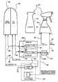
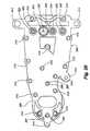
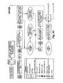
- FIG. 1is a schematic of the flow path circuit and related components of the present invention.
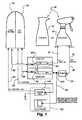
- FIG. 2is a perspective view of the present invention, including a base unit, a spray bottle and a cartridge.
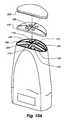
- FIG. 3is an exploded view of the present invention shown in FIG. 2 .
- FIG. 4is a section view of the present invention taken along line 4 — 4 of FIG. 2 .
- FIG. 5is a perspective view of the evaporation media incorporated in the present invention.
- FIG. 6is a front view of the removable cartridge.
- FIG. 7is a bottom view of the removable cartridge and shows the ports for interconnecting with the circulation path formed in the base unit.
- FIG. 8is a rear view of the removable cartridge.
- FIG. 9is a section view of the removable cartridge, taken along line 9 — 9 of FIG. 8 , including the cover, filter, de-ionization resin, serpentine region, diffuser plate, and inlet plate.
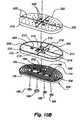
- FIGS. 10A and Bare an exploded view of the cartridge.
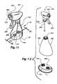
- FIG. 11is a perspective view of the spray bottle version of the reservoir.
- FIG. 12is an exploded view of the spray bottle shown in FIG. 11 .
- FIG. 13is a partial section view taken along line 13 — 13 of FIG. 11 , showing the valve assemblies at the bottom of the bottle, with the bottle placed on the base unit, the valve assemblies in the open position.
- FIG. 14is a partial section view similar to that shown in FIG. 13 , wherein the valve assemblies are closed.
- FIG. 15shows a carafe style reservoir.
- FIG. 16shows an exploded view of the carafe style reservoir of FIG. 15 , showing the valve assemblies similar to those shown in FIG. 13 .
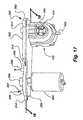
- FIG. 17is a perspective view of the manifold encompassing a portion of the circulation path, the pump and motor, and the ozone generator.
- FIG. 18is a section view of the manifold taken along line 18 — 18 of FIG. 17 , and shows the inlet and outlet ports to the reservoir, the mixing means (venturi) and the top and bottom portions of the manifold.
- FIG. 19is an underside view of the top portion of the manifold, and shows the seal groove, a portion of the circulation path, the mixing means (venturi) and various ports.
- FIG. 20is a top view of the top portion of the manifold.
- FIGS. 21A and Bis an exploded view of the manifold, showing the seal member, pump, ozone generator and cell.
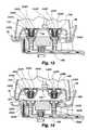
- FIG. 22Ais a section view taken along line 22 — 22 of FIG. 18 , showing the ozone generator, including the cell in the non-engaged position, prior to the pressure increasing sufficiently to move said piston.
- FIG. 22Bis a section view similar to that of FIG. 22A , wherein said piston has been actuated by said water pressure to move and cause said cell to be in the engaged position.
- FIG. 23shows a control panel overlay
- FIGS. 24-28show the block diagram showing the operation steps used by the control unit in controlling the inventive device, correspond to the control panel overlay shown in FIG. 23 .
- FIG. 29shows another control panel overlay.
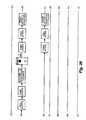
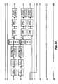
- FIGS. 30-34show the block diagram showing the operation steps used by the control unit in controlling the inventive device, correspond to the control panel overlay shown in FIG. 29 .
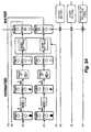
- FIG. 35is the functional block diagram of the control system.
- FIG. 36is another control panel overlay.
- FIG. 37is another control panel overlay.
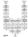
- FIGS. 38-41show the block diagram showing the operation steps used by the control unit in controlling the inventive device, correspond to the control panel overlays shown in FIGS. 36 and 37 .
- the present invention ozonation deviceis a compact and portable system for introducing ozone into water and for providing a convenient means for utilizing the ozonated water.
- the present inventionallows water in a handy reservoir to be ozonated in a simple, convenient and efficient manner.
- the ozonated watercan then be applied to a variety of surfaces for cleaning and/or disinfecting purposes.
- the unit 60includes a base 62 , a reservoir 64 and a filter cartridge 66 .
- the reservoir 64is filled with water and placed on the base 62 .
- the water in the reservoir 64circulates through the base 62 and filter cartridge 66 to become ozonated, and then flows back into the reservoir 64 .
- the filter cartridge 66is a separate element because it requires periodic replacement when its filtering qualities are diminished. It could, however, be built integrally with the base.
- the base 62includes a control unit, using software to control the operation of the ozonating function. For instance, the control unit controls the “charging” of the water with ozone, turns on and off the ozone generator, senses performance (filter cartridge usefulness) and many other features to make the system work.
- the inventionis encompassed by the combination of a base unit 62 , a reservoir 64 and a cartridge 66 .
- the reservoir 64typically defined by a spray bottle or carafe, is removably retained within a recess 68 defined in the top surface 70 of the main housing of the base 62 .
- the water treatment cartridge containing deionization media and lead abatement mediais removably retained within a second recess 72 in the top surface of the main housing.
- An ozone generatoris also contained within the main housing 62 .
- a circulating flow pathis defined between the reservoir, the ozone generator, and the water treatment cartridge 66 .
- a userfills the reservoir 64 and places it in the corresponding recess 68 in the top surface 70 of the main housing 62 .
- Automatic valves 74 formed in the bottom of the reservoir 64form part of the circulation path and connect with valve assembly 78 formed in the surface of the main housing 62 and are in fluid connection with the ozone generator.
- the automatic valves 74work as part of the circulation path to allow water to flow from the reservoir 64 to the ozone generator and back into the reservoir 64 , during operation of the device 60 .
- the usernext actuates the device 60 by a control unit thereby causing both a device pump and ozone generator to actuate.
- wateris circulated from the reservoir 64 to the ozone generator (and also through a deionization media and lead abatement media) and back to the reservoir 64 for a predetermined amount of time. Over time, the level of ozone in the water contained within the reservoir is increased. After the cycle ends, the user simply removes the reservoir 64 from the base and uses it as desired. In an embodiment where the reservoir 64 is defined by a spray bottle, the user might use the ozonated water to clean vegetables or clean countertops.
- FIG. 1is a block diagram that illustrates the water circuit of one embodiment of the present invention.
- the userfills the reservoir 64 , in this case represented by a spray bottle, with tap water and installs it on the main housing 62 .
- the interface between the bottle 64 and the main housing 62contains two one-way valves 74 (one for outflow from the bottle to the main housing and one for inflow to the bottle from the main housing) that cooperate to automatically open when the spray bottle 64 is installed on the main housing 62 thereby allowing water to pass between the base main housing 62 and the spray bottle 64 .
- the userthen activates a start switch of the control unit on the base main housing; the system could also automatically activate.
- the switchactivates the pump, which draws tap water from the spray bottle into the ozone generator contained in the main housing.
- the output of the pumphas three branches including: a recirculation water path to a venturi mixer which then flows back to the bottle; a second flow path to the DI resin bed, which leads to the ozone cell; and a third path that leads a mechanical system to actuate the ozone generator (and thus the ozone cell).
- the water that goes through the recirculation branchflows through the venturi, then flows back to the bottle.
- the water that flows down the second pathis diverted to the DI resin and then through the ozone cell, then back to the venturi to be re-mixed with the water in the recirculation path, which flows back into the bottle.
- the water in the third pathpressurizes a piston assembly in the ozone generator to move one member of the ozone cell towards the other member to complete the cell and start creating ozone for introduction to the water in the second path. This circulation path is described in more detail below with respect to FIG. 1 .
- the ozone cellneeds DI water input to prevent “poisoning” of the cell by ions commonly present in tap water, which would shorten its life.
- the ozone celluses DI water as input and dissociates part of the DI water flowing through it into ozone gas (O 3 ), oxygen gas (O 2 ), and hydrogen gas (H 2 ).
- O 3ozone gas
- O 2oxygen gas
- H 2hydrogen gas
- the H 2 gasdissipates into the air as a waste product.
- the DI water exiting the ozone cellcontains O 2 and O 3 gases. It may also contain trace amounts of dissolved lead from the lead oxide plating used in the cell as a catalyst.
- the cellgenerates the O 3 gas as micro bubbles that dissolve into the water.
- the water exiting the ozone cell(containing O 2 and O 3 gases) flows through a lead removal media to remove any trace amounts of lead.
- the ozonated DI water and ozone gasare fed back into the recirculation water line through a venturi.
- the venturihelps dissolve the ozone into the water. The water then flows back to the bottle.
- the cyclecontinues for a preset amount of time during which the ozone concentration increases in the spray bottle to a desired level.
- the time periodmay vary depending on the size of the reservoir being ozonated. For example, a large reservoir may take approximately 15 minutes, while a small container may take approximately 10 minutes.
- the spray bottle or carafe ozone concentrationis preferably about 2.0 ppm.
- the control unitinstructs the pump and ozone cell to shut off. When the pump shuts off, the pressure on the piston keeping the cell in an operating orientation is released, and a biasing force, such as a spring, moves the movable member of the cell away from the rest of the cell, and thus terminates the ozone production. The user can then remove the reservoir and use the ozonated water to clean and/or disinfect food or surfaces.
- the circulation path 80incorporated in the present invention is disclosed.
- the circulation pathis generally a loop extending between the reservoir 64 and the ozone generator 122 to allow the water in the reservoir 64 to become charged or ozonated.
- the circulation path 80begins and ends in the reservoir 64 .
- the first section 82 of the circulation pathflows from the reservoir 64 to the pump 124 .
- Pump 124comprises an electric motor 286 and a gear pump 288 .
- the waterflows to and through the pump 124 due to gravity as well as the draw created by the pump. After the pump, the circulation path braches into three different paths.
- the first path 84is the recirculation path that flows back to the reservoir 64 through the venturi 308 .
- the second path 86flows to the ozone generator 122 for treatment by the ozone cell 154
- the third path 88flows to the ozone generator 122 to actuate the ozone cell 154 .
- the first path (recirculation path) 84flows through the venturi 308 to allow mixing with the treated water flowing in the second path 86 , after that water has been treated by the ozone generator 122 .
- the water stream in the first path 84 and second path 86recombine at the venturi 308 to flow back to the reservoir 64 .
- the second path (the treatment path) 86splits from the first path 84 in a diverter 90 (such as an aperture) to direct the water to the ozone generator 122 to be treated by the ozone cell 154 .
- the second path 86after splitting from the first path 84 , leads to a DI resin bed 92 to deionize the water prior to the water being treated by the ozone cell 154 .
- the second path 86flows through the ozone cell 154 for treatment thereby.
- the ozone cell 154ozonates the water, as described below.
- the second path 86leads to a lead abatement filter 94 to remove any residual lead that may have been placed in the water stream in the ozone cell 154 .
- the second channel 86flows to the venturi 308 for recombination with the first path (the recirculation path) 84 , which again Rows back to the reservoir 64 .
- the third path 88 formed by the circulation path 80 after the pumpleads to the ozone generator 122 to actuate the ozone cell 154 .
- the ozone generator 122includes the ozone cell 154 and related mechanism that allow the ozone cell 154 to be in one of two positions: 1) disengaged where the ozone cell 154 is not operable, and 2) engaged, where the ozone cell 154 is operable.
- the third path 88actuates the mechanism to cause the ozone cell 154 go change from the first, unengaged position to the second, engaged position.
- the third path 88is a dead leg which creates pressure on a piston 350 (the pressure being developed by the pump) to move the ozone cell 154 into the second, operable position.
- the circulation path shown in FIG. 1is representative of one circulation path only.
- the important pathis the one flowing from the reservoir 64 to the ozone cell 154 and back to the reservoir.
- the pathway through the DI resin bed, or through the lead abatement filterare not necessarily required.
- the pathway to actuate the mechanism to engage the ozone cellis also not necessary where the ozone cell does not require such actuation.
- FIGS. 2-4The spray bottle 64 , base unit 62 , and deionization and lead filter cartridge 66 (cartridge unit) according to one embodiment of the present invention are shown in FIGS. 2-4 . While in the embodiment illustrated in FIG. 2 a spray bottle 64 is illustrated, a carafe or other container can be used in the system providing it includes a valve assembly 74 adapted to work with the valve assembly 78 in the base unit 62 of the system, all as part of the circulation path for charging the fluid in the reservoir 64 (bottle or carafe) with O 3 .
- both the spray bottle 64 and cartridge 66can be removed from the base unit 62 of the system 60 .
- a userwill remove the spray bottle 64 after the water is ozonated to spray the ozonated water as desired.
- the cartridge unit 66will usually remain in the base unit 62 . However, when the filtration media of the cartridge unit 66 is exhausted, the cartridge unit 66 can be removed and replaced with a new cartridge unit 66 .
- the base unit 62is a housing containing: the ozone generator 122 ; the pump 124 and valve assembly 126 for moving the treated and untreated water along the circulation flow path; the control unit 128 for controlling the process; and a substantial part of the circulation path 80 . As illustrated in FIG. 4 , the ozone generator 122 and pump 124 mentioned above are enclosed within the base unit housing 62 . Additional details regarding the spray bottle 64 , the cartridge unit 66 , and the base unit 62 are provided below.
- the base unit housing 62contains the ozone generator 122 , the pump 124 , and the valve assemblies 126 for diverting both treated and untreated water.
- the base unit 62is substantially oval in shape in the lateral dimensions.
- any shapecould be used for the base unit housing 62 so long as the base unit housing design provides stability to hold the spray bottle 64 and cartridge unit 66 and house the ozone generator 122 described below.
- the front and larger recess 68is adapted to receive a lower portion 76 of the reservoir 64 .
- the rear and smaller recess 72is adapted to receive the cartridge unit 66 .
- the bottom surface of the front recessincludes valve assemblies 78 adapted to correspondingly connect with the valve assemblies 74 on the bottom surface of the spray bottle 64 .
- the recess 72 for the cartridge unit 66defines apertures on a bottom wall of the recess to correspond to apertures on a base wall of the cartridge unit. These apertures are part of the circulation path.
- a userplaces the spray bottle 64 in the larger recess 68 towards the front of the top surface 70 of the base unit 62 .
- the userplaces the cartridge unit 66 in the rear recess 72 of the base unit 62 .
- Both the spray bottle recess 68 and the cartridge unit recess 72are configured to securely hold the spray bottle 64 and cartridge unit 66 , respectively.
- the larger recess 68 , or spray bottle recess, as illustrated in FIG. 3includes a raised portion 132 on the bottom surface of the recess 68 .
- the valve assemblies 78 on the base unit 62 for the spray bottle 64reside within the raised portion 132 .
- the bottom 76 of the reservoirdefines a recess 134 having sidewalls and a ceiling (part of the bottom wall of the reservoir).
- the valve assemblies 74 for the bottle 64are in the ceiling of the recess 134 .
- the raised portion 132has the same general shape as the recess 134 , and provides added stability for the spray bottle 64 as it resides within the recess 68 in the main housing. In addition, the shape of the raised surface 132 acts as a key to help the user properly orient the spray bottle 64 within the recess 68 in the main housing 62 .
- a lower front portion of the base unit 136 illustrated in FIGS. 2 and 3defines a shelf 138 .
- the shelf 138includes an interface for the control unit 128 for actuating the device.
- other parameters that affect the dimensions of the base unit 62include the desired water flow capacity of the system, the necessary size of the ozone generator 122 to meet the desired capacity, the power supply, printed circuit board, and other elements.
- a cantilever deflecting rib 142 on the back of the cartridge housingcooperates with a catch 144 on the back portion of the corresponding cartridge recess 72 to releasably secure the cartridge housing 66 within the main housing cartridge recess 72 .
- a power switchis located along one of the side surfaces of the main housing 62 and supplies power to the control unit 128 , the pump 124 , and the ozone generator 122 when turned on.
- the unitis powered by line voltage from regular 110 v electrical service, and can also be battery powered.
- a backside wall 148is vented to facilitate cooling of the generator motor and drying of an evaporation media.
- FIG. 4shows two vents, a first vented area 150 located to reside below the motor, and a second smaller vented area 152 is located to reside below cell chamber 154 .
- An evaporation media 156(see FIG. 5 ) is located adjacent the smaller vented area 152 beneath the ozone generator cell chamber 154 (see FIG. 4 ).
- the evaporation media 156is formed from a sponge-like absorbent material.
- the evaporation mediais configured to collect any moisture that leaks from the ozone generator 122 .
- the vented bottom surface 152 in the lower housing portion and vented sidewall 150 in the back 148 of the upper housing portion 62facilitate drying of the evaporation media 156 .
- FIGS. 6-10Billustrate the cartridge element 66 .
- the cartridgeincludes a cartridge housing 158 having a flat front surface 160 and a rounded back surface 162 .
- the cartridge housing 158contains a DI resin filter separated into several separate but interconnected chambers 172 , and a lead abatement region in a serpentine layout.
- FIG. 6shows the four apertures formed in the bottom of the cartridge. From left to right, aperture 164 is the inlet to the DI chamber. Aperture 166 is the outlet from the DI chamber. Aperture 168 is the inlet to the lead abatement region, and aperture 170 is the outlet from the lead abatement region.
- FIG. 7shows the apertures from a bottom view.
- FIG. 8shows the rib 142 that helps keep the cartridge 66 in the recess 72 .
- FIG. 9is a cross section showing a couple DI chambers 172 , down tubes, fitter tops, and the lead abatement serpentine 178 . These will be described in more detail below.
- FIGS. 10A and Bare front exploded isometric views of the cartridge unit 66 .
- the cartridge unit 66encloses media 180 for deionizing water prior to entering the ozone generator 122 , and the lead abatement filter 178 for removing trace amounts of lead after the water has passed through the ozone generator 122 .
- the cartridge unit 66is divided into two regions, one for the DI water treatment and one for the lead abatement treatment.
- the top chamber 182includes the deionizing media 180 and a bottom chamber 184 includes the lead filter. (See FIG. 9. )
- 10A and Bis generally rectangular in shape, any shape capable of enclosing both the deionizing media 180 and the lead filter 178 is acceptable providing it corresponds with the recess 72 in the base unit 62 of the system 60 and the applicable apertures 164 , 166 , 168 , 170 .
- the two chambers 182 , 184could also be side by side or in any different configuration.
- the back surface 162 of the cartridge housing 158also includes a rib 142 that mates with a catch 144 located on the device base 62 .
- the catch 144operates with the rib 142 on the cartridge 66 to hold the cartridge 66 in place during operation of the device 60 .
- the bottom surface of the cartridge unit 66includes apertures 164 , 166 , 168 , 170 for allowing water to enter and exit both the deionization chamber 182 and the lead filter chamber 184 .
- the aperturescan be watertight fittings that mate with corresponding fittings in the base of the recess 72 for the cartridge 66 .
- O-rings 186 or the likecan be used to allow the fittings to seal tightly together but also provide a removable fit.
- the apertures 164 , 166 , 168 , 170can also be similar to those between the bottom of the reservoir 64 and the circulation path, which are open when engaged and closed when not engaged. This valve variation is described in more detail below.
- the fittings structure(without valves) would be appropriate.
- the fittings, or valves, on the bottom of the recess 72 for the cartridge 66are part of the circulation path, and either lead from the path to the DI water treatment, or from the DI water treatment to the ozone generator 122 or from the ozone generator 122 to the lead abatement region, or from the lead abatement region to the venturi to mix the charged water with the water in the recirculation path.
- the circles illustrated on the left side of the bottom surface of the cartridge unitrepresent an inlet 164 and an outlet 166 for water to enter and exit the deionization media.
- the circles illustrated on the right side of the bottom surface of the cartridge unitrepresent an inlet 168 and outlet 170 for water to enter and exit the lead abatement filter 178 in the cartridge unit 66 .
- the valve assemblies used in one embodiment of the present invention cartridge unitare adapted to cooperate with the valve assemblies in the corresponding cartridge recess in the base unit 62 of the system 60 .
- the valve assemblies utilized in the cartridge unitare substantially similar to those used in the spray bottle 64 and spray bottle recess 68 (described below).
- valve assemblies on the cartridge 66automatically close to seal the cartridge unit 66 .
- the valves assembled on the bottom of the cartridge 66automatically open to allow water to enter and exit the cartridge unit 66 .
- untreated wateris pumped through the deionization media 180 in the cartridge unit prior to introducing the water to the ozone cell. After ozonation, the de-ionized and ozonated water is then fed to the lead abatement filter 178 in the cartridge prior to ultimately exiting the base unit 62 and reentering the spray bottle 64 .
- the top chamber 182 of the cartridge housing 158(see FIG. 9 ) for DI filtering is divided into four quadrants. As illustrated in FIGS. 10A and B , quadrant one 188 is in the upper left hand corner and the remaining quadrants are numbered sequentially in a clockwise manner. Each quadrant forms a sub-chamber that extends the length of the top portion 182 . Each quadrant includes a tube 174 extending the length of the sub-chamber, which tube serves as a down-flow tube. Each sub-chamber is filled with a deionizing (DI) material to de-ionize the tap water used in the device 60 .
- DIdeionizing
- a porous filter 196is positioned at the top of each sub-chamber to collect the DI fines out of the water so they do not clog the venturi.
- the porous filter 196 in each sub-chamberdefines an aperture 198 that fits over the down-flow tube.
- the upper end 200 of the down-flow tubeextends above or flush with the top surface of the filter.
- the filter 196can be one piece, as shown in FIGS. 10A and B , to fit fully over the top of the DI chambers.
- a cover 202fits over the open top of the cartridge and is attached with a watertight seal. There is a space between the cover and the filter to allow the water to flow therebetween. (See FIG. 9. )
- the bottom of the cartridgeincludes three plates delineating two intervening layers.
- the bottom or inlet plate 204forms the four apertures 164 , 166 , 168 , 170 therethrough (described above) to allow in-flow and out-flow to and from the DI and lead abatement regions.
- the top surface of the inlet plateforms a continuous channel in a labyrinth, serpentine-like shape. The channel leads from the inlet of the lead abatement region (aperture in inlet plate) to the outlet of the lead abatement 178 region (aperture in inlet plate).
- the second plate 206has the same labyrinth design on its bottom surface as the design on the top surface of the inlet plate. These two plates are connected together along the common walls of the channel (which weld together) and along the outer rim 208 of the second plate. This forms the labyrinth pathway between the two plates.
- the second platehas two apertures 210 , 212 in it that match and align with the two apertures in the inlet plate that are associated with the inlet 164 and outlet 166 of the DI chamber.
- the top of the second plate 206is divided into four quadrants 224 , 226 , 228 , 230 to match with and seal 214 between the four quadrants formed in the distribution plate, as described below.
- quadrantsalso correspond to the quadrants 188 , 190 , 192 , 194 of the DI chamber.
- the upper left quadrant, or first quadrant, of the second plate 206is sealed to the bottom of the corresponding chamber.
- the DI inlet aperture 164is encompassed by the perimeter of the first quadrant wall in the distribution plate, so the water flows into the first quadrant and up through the DI material in the first DI chamber. More detail on the water flow path is provided below.
- each quadrantdefines a protrusion 218 to encompass a down-flow tube 174 and to divert the water into the next chamber, or to allow the water to enter the first chamber or exit the last chamber and continue on the circulation path.
- a distribution plate 216is positioned above the second plate 206 .
- the distribution plate 216is also separated into the four quadrants on both its top and bottom surfaces.
- the shape of the quadrants on the bottom surface of the distribution plate 216match the shape of the quadrants on the top of the second plate, in order to facilitate the correct water flow from one DI quadrant to another.
- Each of the quadrants in the distribution plateare perforated with small apertures 220 in order to distribute the water somewhat evenly over the cross-sectional area of the DI material 180 in the particular chamber. This helps minimize channeling and increases the efficiency of the effect and length of life of the DI filtration process.
- Each quadrantalso defines a larger aperture 222 that matches with the protrusions 218 in the perimeters of the quadrants on the top side of the second plate 206 .
- Each of these apertures 222seals with the bottom of a down-flow tube 174 to direct the water to the next quadrant, as is explained in more detail below.
- the top surface of the distribution plate 216seals with the quadrant walls of the main body 158 .
- the flow path of the water through the DI chamberstarts at the inlet aperture 164 formed in the inlet plate 204 .
- the waterflows up through the inlet aperture 164 , and up through the inlet aperture 210 in the second plate 206 .
- the wateris distributed through the perforations 220 in the first quadrant section of the perforation plate 216 , and then flows upwardly through the DI material 180 in the first quadrant chamber 188 .
- the waterthen flows through the top filter 196 above the first quadrant 188 and enters the first down-flow tube 174 and flows downwardly to the bottom of the tube and exits into the protrusion 218 that leads the water into the second quadrant 226 .
- the waterthen flows upwardly through the perforations in the second quadrant section of the perforation plate 216 , and then flows upwardly through the DI material in the second quadrant chamber.
- the waterthen flows through the top filter 196 above the second quadrant 190 , and enters the second down-flow tube 200 and flows downwardly to the bottom of the tube and exits into the protrusion 218 that leads the water into the third quadrant 228 .
- the waterthen flows upwardly through the perforations 220 in the third quadrant section 228 of the perforation plate, and then flows upwardly through the DI material 180 in the third quadrant chamber 192 .
- the waterthen flows through the top filter 196 above the third quadrant 192 , and enters the third down-flow tube 174 and flows downwardly to the bottom of the tube and exits into the protrusion 218 that leads the water into the fourth quadrant 230 .
- the waterthen flows upwardly through the perforations 220 in the fourth quadrant section 230 of the perforation plate 216 , and then flows upwardly through the DI material 180 in the fourth quadrant chamber 194 .
- the waterthen flows through the top filter 196 above the fourth quadrant 194 , and enters the fourth down-flow tube 174 and flows downwardly to the bottom of the tube and out the outlet hole in the distribution plate, which is connected to the outlet hole 212 in the second plate, and which is in turn connected to the outlet hole 166 in the inlet plate 204 .
- the waterthen continues flowing along the circulation path to the ozone generator 122 .
- the flow through the DI resin material 180is designed to maximize the residence time of the water with the DI material 180 . This could also be done with various other flow geometries inside of the cartridge 66 , or inside the base housing 62 if this portion of the circulation path was designed to be inside the main housing.
- the inlet 164 and outlet 166 ports of the DI material flow-pathare sealingly engaged (such as with o-ring seals to allow a removable engagement) with the corresponding circulation flow path structures.
- the waterflows through the enlarged port 166 and into the ozone generator cell chamber 154 .
- Deionized wateris used to prevent “poisoning” the ozone generation cell by ions in tap water, which could shorten the cell life.
- Distilled watercould also be used in place of deionized water to prevent poisoning of the ozone generation cell by ions in tap water. While not necessary, in practice, utilizing deionization is a cost effective way of pre-treating the tap water.
- the wateris pumped into the bottom chamber 184 of the cartridge housing 158 and into the lead abatement section 178 to remove any trace amounts of lead that may be present in the water.
- the ozonated waterenters the cartridge housing via the lead abatement inlet port 168 .
- the ozonated waterenters the labyrinth pathway channels defined by the underside of the labyrinth plate and the inlet plate, as described above.
- the ozonated waterflows through lead removal resin that resides in the labyrinth pathway channels 232 .
- the labyrinth pathway channels 232are comprised of small channels containing lead abatement material, and the channels serve to keep the velocity of the gas/fluid mixture high enough to transport the gases through the lead abatement resin thereby preventing gas from being trapped in the cartridge housing.
- the labyrinth channels 232are 0.125 inches by 0.100 inches.
- the lead removal resinwill substantially remove any trace amounts of lead.
- the preferred lead abatement resinis activated alumina. Typical activated alumina beads are 0.06-0.09 inches in diameter. However, other lead removal resins could be utilized (e.g., ATS coated alumina).
- the ozonated waterexits the cartridge housing 158 via the lead abatement exit port 170 .
- the waterflows from the fourth port and re-enters the ozone generator 122 , flowing into the channel that leads to the venturi for re-introduction into the circulation stream.
- the lead abatement mediumis not necessary given the slight levels of lead that might be found in the ozonated water. In the case where it is unnecessary, the lead abatement material can simply be removed from the lead abatement region of the cartridge, or the flow path can be modified altogether to flow directly from the ozone cell to the venturi.
- the DI resin 180generally loses its effectiveness after approximately 300 ozonation cycles.
- the flow control software described belowincludes a counter that counts the number of ozonation cycles run through a filter. As described in more detail below, an alarm and signal notifies the user when the DI resin 180 requires replacement. In other embodiments, the status of the DI resin could be indicated using color indicating resin or from an alarm or indicator that is activated based on the results of conductivity measurements of the DI resin 180 .
- a tall, cylindrical DI resin chamberhas been found to be effective.
- the four-quadrant columnar chambersgenerally replicate the preferred geometry by connecting 4 shorter length chambers. This design is preferred to provide a design with a lower profile.
- a mixed bed DI resinis utilized.
- the resinis comprised of both anion and cation exchange resins, which can be synthetic, natural (such as zeolite).
- Other suitable DI resinsinclude product number MBD-10-NS from RESINTECH, Inc., which is a combination anion/cation resin, or equivalent.
- the cartridge housing 158 and related elementsare generally constructed of ABS, white, RM No. 20000839 (Virgin). Alternate materials include but are not limited to regrind ABS, white, RM No. 20000840 (25% blend).
- FIGS. 11 and 12illustrate a spray bottle 64 that can be used as part of the present invention.
- a spray bottle 64allows the user to spray the ozonated water on surfaces, foods and vegetables, and clothing.
- the present invention spray bottle 64includes a hand-actuated spray nozzle 234 with a tube 236 extending to the bottom of the bottle 64 as known in the art; preferably the present invention spray nozzle is adjustable and can provide a fine stream spray or a wide stream spray.
- the spray nozzleremovably attaches to a transparent spray bottle 238 .
- the spray nozzle 234is removed from the spray bottle for the purpose of filling the spray bottle 238 with water.
- the spray bottle portionis generally well known in the art.
- the spray bottleincludes valve assemblies 74 on its bottom surface 76 .
- the bottom surface 76 of the spray bottleincludes a portion that extends upwardly into the spray bottle to form a recess 134 .
- the recess 134is configured to receive the raised portion 132 on the bottom surface of the spray bottle recess 68 in the base unit 62 .
- the bottom surface 76 of the spray bottle 64includes valve assemblies 74 adapted to connect with the valve assemblies 78 located on the bottom surface of the spray bottle recess 68 in the base unit.
- the valve assemblies 74 on the bottom surface of the spray bottleare adapted to automatically close when the spray bottle 64 is removed from the base unit recess 68 , thereby effectively sealing the bottom surface 76 of the spray bottle 64 .
- valve assemblies 74 on the bottom surface 76 of the spray bottle 64automatically open and cooperate with the valve assemblies 78 on the bottom surface of the spray bottle recess 68 to allow water to flow in and out of both the spray bottle 64 and the base unit 62 .
- valve assemblies 74 on the bottom of the bottlework with the corresponding valve assemblies 78 positioned in the aperture at the bottom of the bottle recess 68 in the main housing 62 .
- the front aperture 78 A in the main housing recess 68allows water to flow from the bottle 64 into the main housing 62 and to the ozone generator 122
- the rear aperture 188allows water to flow from the main housing 62 (already having been treated by the ozone generator and the venturi) and back into the bottle 64 .
- the bottle 64 and inlet 74 A and outlet 74 B valvesare part of the circulation path.
- the front 74 A and rear 74 B outletscan be reversed or re-positioned with the appropriate changes being made to the circulation path structure inside the main housing.
- the valve assemblies 74 A, 74 B on the bottom of the bottleeach include a collar 240 A, 240 B forming the aperture, a pin 242 A, 242 B extending down into the aperture, a plug 244 A, 244 B slidably positioned on the pin 242 , a spring mechanism 246 A, 246 B biasing the plug 244 into the lower, closed position, and a screen 248 A, 248 B covering the top opening of the collar 240 .
- the collar 240is slightly cone-shaped (smaller diameter downwardly positioned) to allow the tapered plug 244 to seat in the collar 240 and make a watertight seal when in the lower position.
- the spring 246keeps the plug 244 in the seated position.
- the plug 244can be slid upwardly along the pin 242 to an unseated, or unsealed, position by an adequate force. When the force is removed, the plug 244 is biased back into the seated position by the spring 246 .
- the valve assemblies 78 A, 78 B in the bottom of the recess in the main housing 62each include an outer flange 250 A, 250 B forming the aperture into the main housing 62 .
- Each flange 250also forms an annular groove 252 A, 252 B around a stand tube 254 A, 254 B for receiving the bottom end of the collar 240 .
- the stand tube 254extends upwardly from the groove 252 in the center of the flange 250 .
- the stand tube 254extends sufficiently above the bottom of the annular groove 252 such that when the bottle 64 is placed in the recess 68 and the corresponding two valve assemblies 74 , 78 engage, the stand tube 254 pushes the plug 244 upwardly enough to move it to an unseated position in the collar 240 (see FIG. 13 ). This allows water to either flow out of bottle 62 through the particular valve assembly 74 A, or into the bottle through the other valve assembly 74 B.
- the sprayer mechanism assembly 234is generally typical of those found in the art.
- the present invention sprayer mechanism assembly 234has a nozzle 256 that is designed to not atomize the mixture while spraying.
- the present invention sprayer mechanism assemblyreduces the amount of mist created while the mixture is being sprayed. It is designed to eject small streams of the mixture, which helps keep the ozone gas in the liquid.
- the stream spraybasically has a larger stream size than normal to keep the stream from misting when sprayed.
- the nozzleincludes six holes: three inner holes 258 and three outer holes 260 .
- the nozzleprovides at least two modes of spray: 1) where the nozzle is completely open or unscrewed, all six streams 258 , 260 combine to form a spray; and 2) where the nozzle is screwed all the way in, the three outside streams 260 are blocked and only the three smaller holes 258 combine to form spray.
- the nozzle 256may also include a fully closed position that prevents fluids or gases from escaping the spray bottle. In one embodiment, all of the holes in the nozzle are 0.04 inches in diameter. In normal operation, approximately 2.5 ml of mixture is ejected from the sprayer per spray. By avoiding atomization of the mixture, the ozone loss is limited to 20-30% each spray.
- the sprayer mechanism assembly 234is configured to releasably attach to an open top portion of the spray bottle portion 238 .
- the grooved collar 262releasably attaches to a threaded open top portion 264 of the spray bottle 238 . Fluid and gases contained in the sprayer bottle 64 are drawn into the body and forced out of the sprayer nozzle by squeezing the trigger.
- the sprayer bottle portionis a typical polymer based material and is typically formed from two pieces: a body portion 268 ; and a bottom portion 76 .
- the two piecesare typically sonically welded together. In one embodiment, it is substantially transparent to allow the user to view the contents of the bottle 64 .
- the top of the body portionis threaded to allow mating with the collar on the sprayer mechanism assembly.
- the shape of the body portion bottomis configured to attach to the and to fit within the reservoir container recess formed in the top surface of the upper housing portion of the main housing.
- the bottom of the bottleincludes the valve assemblies.
- FIGS. 15 and 16A reservoir container having a carafe body 272 , a lid 274 , and a bottom 276 including the valve assemblies 74 A, 74 B (same as valve assemblies 126 ) is illustrated in FIGS. 15 and 16 .
- the lid snap 274fits to the carafe body 272 and can be opened during use.
- the body 272includes a v-notched pour spout 278 for directing fluids while pouring.
- the carafe container 270allows a user to introduce gross quantities of treated water to selected areas or surfaces. Examples of such uses include pouring treated water over plants, over fruits and vegetables, and into drinking containers.
- the carafe container 270includes the same valve assemblies used in the spray bottle and described above. Other types of containers could be utilized in the present invention providing they include valve assemblies capable of cooperating with the main housing valve assemblies.
- the front shelf portion 138 of the upper housing portionincludes a control panel on its surface.
- the control panelis operably connected to a control unit 128 circuit board (discussed later).
- the control panelis configured to include push buttons that allow the user to operate the functions of the device. A more detailed description is provided below.
- a manifoldis secured to the upper housing portion of the main housing 62 .
- the manifoldincludes an upper 282 and lower 284 housing portion, the lower portion containing the ozone generator 122 depending downwardly therefrom at one end.
- an electric motor 286depends downwardly from the lower manifold 284 .
- the motoris used to drive the gear pump 288 , as is described in greater detail below.
- the lower manifold 284forms the bottom surface 290 of the manifold 280 .
- the upper manifold 282forms the top surface of the manifold 280 .
- the gear pump motor 286resides below and is connected to the gear pump 288 , which is located in the gear pump housing 294 formed in the upper manifold 282 .
- the ozone generator 122is suspended from the right side of the manifold as shown in FIG. 18 .
- the flow ports that allow water to flow to and from the ozone generator 122are located above the ozone generator 122 on the right side of the manifold.
- the left-most stand tube 296defines the port 297 that allows water to flow from the reservoir container 64 into the manifold 280 .
- the next stand tube to the right 298allows water to flow out of the manifold 280 and back into the reservoir 64 after treatment.
- Other aperturesare formed in the upper manifold to allow flow to and from the cartridge 66 .
- FIG. 18shows various parts of the circulation path 80 formed in the manifold.
- the waterenters the manifold 280 from the reservoir 64 through the valve assembly 126 associated with the left-most aperture or port 297 .
- the gear pump 288driven by the motor 286 , draws the water from the reservoir 64 (with the aid of gravity) and generates sufficient pressure to push it through the rest of the circulation path 80 .
- the motordrives one gear 300 , which is engaged with a second free-floating gear 302 , and together this gear pump 288 creates sufficient pressure to push the water through the circulation path 80 .
- the second region 306 shownis the venturi 308 and exit from the manifold 280 back into the reservoir 64 .
- the venturi 308is formed to take water from the recirculation path 342 and from the ozone generator 122 and mix the two streams together in the venturi 308 .
- the mixed waterthen flows back into the reservoir 64 through the valve assembly 126 associated with the right-most aperture or port 299 .
- FIG. 18also indicates that the top of the lower manifold portion 284 is relatively planar, with the flow paths being formed by the seals 310 held in place against the lower manifold by the upper manifold. This will be described in more detail later.
- FIGS. 19 and 20provide additional details on the ozone generator system of the present invention.
- the flow path of the water in the ozone generator systemis best illustrated in FIG. 19 .
- FIG. 19shows the bottom surface 312 of the upper manifold portion 282 .
- the bottom side 312 of the upper manifold 282includes tabs 314 , screw holes 316 , and various grooves 318 .
- the overall shape of the upper manifold 282is configured to fit within the base housing 62 of the present invention device, and to fit precisely with the bottom manifold portion 284 .
- the upper manifoldincludes mounting tabs 314 .
- the mounting tabsare used to mount the manifold inside the device base housing. In FIG. 19 , four mounting tabs 314 are illustrated. However, in other embodiments, more or less mounting tabs may be utilized.
- the upper manifold 282also includes multiple screw holes 316 .
- the screw holes 316are used to attach the upper manifold 282 to the lower manifold 284 . In addition to screw holes 316 and screws 317 , other means for attaching the upper and lower manifolds could be utilized. Other means include detent structures or rivets, or the like.
- the bottom surface 312 of the upper manifold 282also includes a series of grooves 318 .
- One groove 318 Ais for receiving the seal 310 between the upper and lower manifolds, and the other 318 B forms the physical channels of the portion of the circulation path 80 formed in the manifold 280 .
- the outermost groove 318 Ais a groove for receiving a housing seal 310 .
- the housing seal groove 318 Ais generally exterior to other grooves in the bottom surface of the upper manifold 282 .
- the housing seal groove 218 A, in combination with the seal 310generally provides a seal around all water-flow channels and ports between the upper and lower manifolds.
- the seal 310is generally a rubber, plastic, or similar material formed to fit in the seal groove 318 A and for a water tight seal when clamped between the upper and lower manifolds. Both the water flow channels and ports are discussed in greater detail below.
- the housing seal 310is received by the housing seal groove 318 A and sandwiched between the upper 282 and lower 284 manifolds.
- the housing seal 310serves to prevent any fluids from leaking out of the circulation path and manifold.
- an outer groovemay be formed on the lower manifold (outside of the housing seal). This outer groove serves to direct any water that leaks past the housing seal (out of the generator) to an evaporation media (discussed below).
- the bottom surface 312 of the upper manifold 282also includes the channels 320 that form the portion of the circulation path 80 that is formed by the manifold 280 .
- the water-flow channels 318 B within the upper manifold bottom surfaceare generally U-shaped open channels for ease of manufacture.
- the flat lower manifold 284covers the U-shaped channel 318 B to form a generally rectangular channel.
- any shape of channel cross section, such as cylindrical channels,could be used in other embodiments (upper and lower manifolds joined to form a cylindrical channel).
- the rectangular channelsare 0.02 inches wide by 0.02 inches deep.
- FIG. 20illustrates a top view of the upper manifold 282 .
- Mounting tabs 314 and screw holes 316are also formed in the upper manifold 282 .
- the stand tubes 296 , 298 , 322 , 324 , 326 , 328 that connect the reservoir container 64 to the manifold 280 , and the cartridge 66are also illustrated in FIG. 20 .
- On the left-most end of the top surface of the upper manifold 282is the port 297 through which the water flows from the reservoir 64 to the manifold 280 .
- the next stand tube to the right 298allows water to flow from the manifold 280 back into the reservoir container 64 .
- the stand tubesmay also include a porous plastic screen, or other such device, to prevent debris from clogging the venturi 308 .
- the top port 330 in FIG. 20allows water to exit the manifold 280 and flow to the DI resin located in the cartridge housing 66 .
- the second port 332 just below the DI resin port 330is enlarged. The enlarged port 332 allows water to flow from the DI resin back into the ozone generator 122 and into the ozone reaction chamber or cell 154 .
- the third port 334allows water to flow from the ozone reaction chamber or cell 154 to a labyrinth containing lead abatement resin.
- the labyrinth and lead abatement resinare located in the bottom portion of the cartridge housing 66 .
- the bottom-most or fourth port 336allows water to flow from the lead abatement resin in the cartridge housing 66 back into the manifold 280 and towards the venturi 308 .
- Water entering the manifoldflows from the reservoir container 64 , through a valve tube, and into a stand tube 296 , as illustrated in FIG. 20 , and into the receiving channel on the upstream side of the gear pump housing 294 .
- the upstream side of the gear pumpingis the side closest to the port 297 where water enters the fluid circuit from the reservoir container 64 .
- waterenters the generator on the left side of the upper manifold bottom surface 312 . Water is pumped to the right as shown in FIG. 19 within the manifold 280 by a gear pump 288 that resides in a gear pump housing 294 recess.
- the gear pump 288draws water from the reservoir container 64 (e.g., spray bottle or carafe) and through the gear pump housing 294 recess and pumps it along the circulation path 80 in the manifold 280 .
- the gear pump 288is located outside of the ozone generator 122 .
- the wateris pumped along the circulation channel to a first junction 340 (see FIG. 1 or 19 ).
- the channelbranches toward a recirculation channel path 342 and a second way toward the DI resin (DI water path) 344 .
- DI resinDI water path
- the water channel 344 leading to toward the DI resinalso further branches to a dead leg path 346 that causes pressure to build on the upstream side 349 of the piston 350 in the ozone generator (system actuation path), as described in some detail here, and in more detail below.
- the pressure on the piston 350serves to actuate a diaphragm/anode post assembly. When the diaphragm/anode post assembly is actuated, the ozone generation cell and cycle is activated (system is actuated).
- the second path channel 344 that flows towards the DI resin chamberalso flows to the dead-leg channel 346 to actuate the piston 350 .
- the water flowing to the DI resin chamberflows upwardly out of the manifold 280 through aperture 330 , and the water that is used to pressurize and actuate the piston flows downwardly into the ozone generator 122 .
- the water flowing toward the DI resinexits a port in the top surface 330 of the upper manifold and enters a DI resin chamber 182 that is housed in the cartridge housing (described above) 66 .
- the wateris deionized prior to entering the ozone generation cell to prevent “poisoning” of the cell by ions in the tap water.
- the use of deionized water in the reservoir container 64would eliminate the need for DI resin.
- the deionized waterAfter circulating through the DI resin, the deionized water enters the ozone generator 122 .
- the deionized waterenters the ozone generator through the enlarged port 332 (as illustrated in FIG. 20 ).
- the deionized waterthen flows into and through the ozone cell 154 .
- the deionized wateris ozonated.
- the anode 356 and possibly other components of the ozone cell 154are possibly plated with lead dioxide. Lead dioxide serves to increase the electrochemical reactions that produce ozone gases.
- the ozonated wateris now a mixture of H, O 3 , O 2 , and H 2 O.
- the ozonated mixturethen exits the ozone generator 122 and re-enters the cartridge housing 66 .
- the water exiting the ozone cell 154is then run through the lead abatement media (as described above) to remove any trace amounts of lead that may exist in the ozonated water.
- the ozonated watercirculates through a labyrinth filled with lead abatement resin and then re-enters the ozone generator 122 .
- the ozonated water exiting the lead abatement labyrinthre-enters the ozone generator via the bottom-most port 336 (as illustrated in FIG. 20 ).
- the ozonated waterthen flows along a channel 352 formed in the bottom surface of the upper manifold 282 and flows to the venturi 308 .
- the ozonated wateris mixed with water flowing in the re-circulation line 342 .
- the mixture of ozonated and re-circulated waterthen flows into an exit channel 354 .
- the ozonated mixtureexits the manifold 280 through a stand tube 298 and valve assembly (as described above) and enters the reservoir container 64 .
- the re-circulation streamflows at 300 ml/minute and the stream flowing through the DI resin and ozone generator flows at 20 ml/minute.
- the stream ratesmay vary (e.g., re-circulation stream of 200-400 ml/minute).
- the venturi 308helps to promote dissolution of the ozone in the water via the following means: by creating a turbulent zone that increases the contact time of the ozone with the water; and by shearing ozone bubbles into smaller bubbles to increase the overall surface area of ozone in the water.
- the venturi design geometrycan affect the pressure loss experienced through the venturi.
- the venturi inlet angleis 20° and the outlet angle is 7°.
- the venturi in the present inventionis formed from rectangular channels 318 B (U-shaped channel in upper manifold bottom surface covered by flat lower manifold surface to form a rectangular channel). In other embodiments, cylindrical channels could be used (as formed by upper and lower manifold surfaces).
- the rectangular channelsare 0.020 by 0.020 inches.
- the accelerated waterbasically collides at an intersection thereby increasing the mixing of the two flows entering the venturi.
- the resulting mixed flowenters a third channel.
- the third channelincreases in diameter to help reduce the velocity of the flow.
- venturi 308benefits the ozonation of the water by helping mix the ozone into the recirculation path of the water
- any mixing device or meanswould suffice, but possibly not be as effective.
- the inventioncan work without the venturi 308 or any type of mixing means.
- Other types of mixing meansinclude converging flowpaths (whether at acute, obtuse, or right angles), perforated screens, mechanical mixers, or any other type of structure or system that cause the ozonated sample of water to flow into an untreated stream and mix the two together.
- a gear pump 288draws water from the reservoir container 64 and into the fluid circuit. The majority of the water flows into the re-circulation path 342 towards the venturi 308 . The balance of the water flows into the DI path 344 towards the DI resin. The water flowing into the DI path also flows to into a dead leg 346 that forms the system actuation path 348 . The system actuation path dead-ends into the upstream side of the piston 350 . The water flowing into the system actuation path 348 causes a pressure of 20-30 psi to build against the upstream side of the piston 350 thereby causing the piston to move forward.
- the pistonBy moving forward, the piston causes the diaphragm/anode post assembly to move the anode 356 into contact with the proton exchange membrane 358 thereby actuating the ozone generator.
- the water flowing into the DI resincirculates through the DI resin and then enters the ozone generation cell 154 .
- the ozonated waterre-enters the cartridge housing and flows through the lead abatement labyrinth in the bottom of the cartridge housing 66 .
- the ozonated, lead abated waterre-enters the fluid circuit and flows to the venturi 308 .
- the re-circulation path 342 and ozonated water path 352are mixed together and combine at the venturi intersection 309 .
- the ozonated mixturethen enters the return path 354 and flows into the reservoir container.
- the ozone generator 122providing the source of the ozone for application to the water is shown.
- the ozone generator 122generally includes the ozone cell 154 and the housing 366 , a mechanism for actuating the ozone cell, and flow-paths for passing water past the ozone cell.
- the ozone cell 154is described in detail in U.S. patent application Ser. No. 60/261,101, filed Jan. 10, 2001, which application was earlier incorporated by reference herein. A description of the ozone generator 122 is provided below also.
- the ozone generator 122includes a housing 366 having three openings therein.
- One opening 360forms part of the dead-leg channel 346 to pressurize the piston 350 and actuate the ozone cell 154 .
- Another opening 362allows the water flowing from the DI chamber to enter the ozone cell and help the reaction to create ozone and ozonated the water.
- the third opening 364leads to the lead abatement chamber which removes any lead that might have migrated into the water during the ozonation process.
- the housing 366also defines a cylinder piston chamber 368 having a first diameter, a cylindrical retaining chamber 370 at the end of and opening to the piston chamber 368 having a second diameter (forming an annular spring shoulder between the two), and a diaphragm recess chamber 372 having a third, smaller diameter opening to the retainer chamber 370 (forming an annular seal wall 374 at the end of the retainer wall 376 ).
- a fourth, and smallest, cylindrical anode bore 378extends from the diaphragm recess chamber 372 .
- Each of these chambershave a common axial center-line.
- a cap 380is sealingly attached to the open end of the piston chamber 368 .
- a rod 382is positioned to extend down the center of the interconnected chambers and act as a piston rod.
- a piston 350At the right end of the piston rod is fixedly attached a piston 350 , which is sealingly engaged with the sidewalls of the piston chamber 368 , by such means as an o-ring 384 .
- the axial movement of the piston (and thus the rod)is defined by the engagement contact with the cap at one end (bottom dead-center) and by engagement with the annular spring shoulder 388 at the other end (top dead-center).
- a spring washer 390is positioned between the piston 350 and the spring shoulder 388 to bias the piston in the bottom dead-center position against the cap 388 .
- the pressurized side of the pistonis between the piston and the cap.
- the first aperture 360 mentioned aboveallows the water to flow into the pressurized chamber and cause the piston to move from bottom dead-center ( FIG. 22A ) to top dead-center (FIG. 22 B). This is the dead-leg channel 346 , since once the piston is moved to top dead-center, the flow into this leg substantially stops except to maintain the pressure.
- the pressureis created by the pump 288 , as described above.
- a diaphragm 392is positioned on the rod at about a mid-point along its length.
- the diaphragm 392is flexible, and has a general circle shape with one circumferential fold 393 .
- the rod 382extends through the center of the diaphragm 392 , and is fixedly and sealably attached thereto.
- the diaphragm 392is positioned in the diaphragm recess chamber 372 , and the circumferential edge of the diaphragm 392 is held against the annular seal wall 374 by a retainer 394 .
- the retainer 394has a bore 396 formed radially therein at one location to allow any seepage past the piston 350 to leak out of the housing 366 onto the evaporation media 156 .
- the diaphragm 392stretches, and the circumferential fold 393 extends to allow the rod 382 to move without restriction, while retaining a hermetic and watertight seal between the retainer chamber 370 and the diaphragm recess chamber 372 . This keeps any water that might be contaminated with lead from migrating out of the system and into the circulation path without going through the lead abatement region.
- An anode 356(electrode) is attached to the end of the rod 382 .
- the anode 356is circular in shape to closely match the bore of the anode bore 378 .
- a sealing engagement hereis not needed, however.
- the second aperture 166 noted above(from the DI chamber portion of the cartridge) is positioned to open into the diaphragm recess chamber 372 to allow water to flow into the ozone cell.
- the anode post 382is press fit into the piston 350 making a piston/diaphragm/anode post/anode assembly (with the piston 350 oriented to the outside of the cell and the anode 356 adjacent to the center of the cell).
- the downstream side 351 of the pistonis at atmospheric pressure.
- the port 334 entering into the lead abatement region of the cartridgeis also open to the diaphragm recess chamber 372 to allow the ozonated water to flow there once charged with ozone.
- the lead abatement port 334is the exit path for the water from the ozone cell 154 .
- the operation of the ozone cell 154causes the oxygen and ozone to form in the chamber adjacent the anode 356 , and as this chamber is full of water, the ozone is introduced to the water and swept with it (under the flow caused by the pump 288 ) up the exit port 334 and into the lead abatement chamber.
- the hydrogenmigrates to the cathode 398 and dissipates into the air beyond the cathode 398 .
- a cathode 398is held in position at the end of the anode bore 378 by a cylindrical retainer 400 .
- the cathode 398has the membrane 358 (proton exchange membrane) attached to the surface exposed to the anode 356 .
- the anode 356contacts the membrane 358 .
- An electrical contactis made to the anode post by a metal stampings 402 attached thereto, which is in turn connected to the power supply through the control unit.
- An electrical contactis made to the cathode 398 by a metal stamping 404 attached thereto (trapped between the retainer and the cathode), which is in turn connected to the power supply through the control unit.
- the control unitenergizes the cell as appropriate to start producing ozone when the anode 356 contacts the membrane 358 .
- the gear pump 288causes water to flow against the upstream side 349 of the piston 350 thereby causing pressure to build against the upstream side of the piston.
- the pressure on the upstream side 349 of the piston 350causes the piston and the anode post assembly connected to the piston to move toward top dead-center.
- the anode 356 attached to the end of the post assemblyis pushed into contact with a proton exchange membrane 358 .
- the proton exchange membrane 358is connected to a cathode 398 .
- Both the anode post and the anodeare preferably constructed of titanium to prevent their oxidation in an ozone environment.
- the anode 356is fabricated using porous titanium to allow the ozone and oxygen created by the operation of the ozone cell 154 to flow through the anode 356 .
- the diaphragm 392is fabricated from an ozone resistant material (e.g., silicone rubber). The diaphragm 392 forms a pressure seal within the cell. On the upstream side of the diaphragm (the piston end), pressure builds to 20-30 psi during operation. On the downstream side 351 of the piston 350 (the anode end), the pressure remains at atmosphere at all times. Because the pressure on the downstream side 351 remains at atmosphere, the reaction chamber 154 is full of water at all times (in and out of operation) and the velocity of the water flowing through the generation cell is reduced.
- the anode 356is electroplated to include lead dioxide (lead dioxide is used as a catalyst in the ozone generation cell).
- a proton exchange membrane 358is sealed against the interior wall of the generation cell by the cathode.
- a negative electrical stamping 404makes the electrical connection to the cathode 398 .
- the negative electrical stamping 404includes an arm that extends from the side of the generation cell and is connected to a power source.
- the proton exchange membrane 358 , cathode 398 , and negative electrical stamping 404are retained in the generation cell chamber 154 by screwing in the cathode plug retainer 400 .
- Water pressure(created by the pump described above) applied to the piston 350 on the opposite side of the piston spring forces the piston/diaphragm/anode post/anode assembly until it bottoms out on the proton exchange membrane 358 (PEM).
- PEMproton exchange membrane 358
- a pressure of 20-30 psibuilds on the up-stream side 349 of the piston 350 and causes the piston to move approximately 0.07 to 0.08 inches to contact the PEM.
- the piston spring 390is a 3-coiled wave washer. The contact of the anode 356 against the PEM completes the electrical circuit, which starts the electrochemical production of ozone. Water traveling though the cell chamber of the lower manifold 284 transfers the ozone gas to the remainder of the water circuit (discussed further below).
- the motor 286is connected to the end of the lower manifold 284 at the opposite end of the manifold from the ozone generator 122 .
- the motor 286cooperates with the gears to form a gear pump 288 .
- the motor shaft 406extends up into a receiving collar 408 and aperture 410 .
- the aperture 410is configured to allow the shaft 406 to be received by a corresponding aperture in one of the gears 300 , see FIG. 21A , retained in the gear pump housing 294 .
- the motor shaft 406operates to turn the gear 300 .
- the teeth on the first gear 300are inter-engaged with teeth on a second, free-wheeling gear 302 thereby causing said second gear 302 to turn also.
- FIG. 21Bthe motor shaft 406 operates to turn the gear 300 .
- a shaft seal 412fits around the motor shaft 406 and in between the top surface 414 of the motor 286 and the interior surface of the receiving collar 408 .
- the shaft seal 412prevents any water from migrating from the gear pump housing 294 in the upper manifold 282 to the receiving collar 408 thereby preventing leakage in this area.
- the base unitcould be built into an appliance, such as a clothes washer, clothes drier, dishwasher, refrigerator, cabinet, or sink.
- the base unitcould be built into a counter top, or be permanently mounted below a cabinet or in a cupboard.
- the deviceis constructed by connecting the circuit board and ozone generator to the underside of the upper housing portion, connecting a power source and power source leads to both the ozone generator (negative and positive stampings) and to the motor, and placing the upper housing portion over the lower housing portion.
- the upper and lower housing portionscan be connected to one another using a detent-type structure, hot plate welding, epoxy, or similar means.
- the control panelis then fixed to the front shelf portion of the upper housing portion (the control panel is operably connected to the circuit board).
- the control panelincludes buttons that the user can press to select their desired mode of operation for the device.
- the control panelis operably connected to a circuit board.
- the circuit boardincludes memory means that store device process flow software, a clock for timing the flow, and other necessary control instructions. These features are generally well known in the art, but are part of a unique combination as used here.
- the combination of the control panel, circuit board, and device process flow softwareare operably connected to the device components and serve to control the operation of the device.
- the control panelincludes the following buttons and light emitting diodes (LEDs): filter status LED; reset button; start/stop button; power on and 2-minute timer LED; and an ozonated water timer LED.
- LEDslight emitting diodes
- both the filter status LED and the ozonated water timer LEDsare one color (the filter status is red and the ozonated water timer is green), and the power on and 2-minute timer LED is two color (orange/green).
- Alternative embodimentsmay use different colors for the LEDs.
- FIGS. 24-28illustrate the process flow for the first embodiment and correspond to the control panel in FIG. 23 .
- the useroperates the present invention device by first plugging the device into an electrical outlet (or by providing the required power source, which may include batteries) and turning the power button or switch to an on position (some embodiments may not include a power button or switch but instead will either maintain a continuous on status, or will power on under other circumstances, such as when the reservoir is filled or placed on a base).
- the usermust fill the respective reservoir container (i.e., spray bottle or carafe) with water and place it in the recess on the base of the main housing, the user can check the operational status of the device by viewing the color of the control panel buttons or LEDs.
- a power LED that is green and blinkingindicates that the cell voltage is either high or low and the unit will not respond to user input, in which case the system should be returned to the manufacturer for service. However, if the power LED is orange, it is an indication that the filter has been set to prime before the next cycle and the unit is ready to operate.
- the device process flow softwareUpon starting the device, the device process flow software will also check the filter status. If the filter usage has reached a preset accumulated usage time limit (generally measured in hours), an audible alarm sounds and half of the filter status LED lights in red. The user will be required to replace the filter and press and hold the reset button for 2 seconds to reset the filter. After replacing the filter and resetting the filter, the filter status LED will return to an unlit state, the filter usage timer will reset to zero, and the filter will be set to prime at the next ozonation process. At this point, the power LED should be orange indicating the unit is ready to operate.
- a preset accumulated usage time limitgenerally measured in hours
- an audible alarm sounds and half of the filter status LED lights in redThe user will be required to replace the filter and press and hold the reset button for 2 seconds to reset the filter.
- the filter status LEDAfter replacing the filter and resetting the filter, the filter status LED will return to an unlit state, the filter usage timer will reset to zero, and the filter
- the filter usagehas exceeded a preset accumulated time limit by a certain preset amount (X+Y hours)
- a certain preset amountX+Y hours
- the filter status LEDfully lights in red.
- the filter preset accumulated time limitis 10 hours
- the X+Y alarmmay be programmed to activate if the user goes past the preset limit by more than twenty-percent (2 hours) thereby causing the alarm to activate at 12 hours.
- a fully lit filter status LEDwill cause both the reset button and the start button to become inactive.
- the userpresses both the reset button and the start/stop button at the same time. Pressing the reset button alone will not affect the operation of the unit in any way.
- the userwould replace the filter and press and hold the reset button for 2 seconds to reset the filter.
- an audible alarmwill sound and the filter status LED will return to an unlit state, the filter usage timer will reset to zero, and the filter will be set to prime at the next ozonation process.
- the power LEDshould be orange indicating the unit is ready to operate.
- the usercould continue to use the unit without replacing the filter by simply pressing and holding the reset button for 2 seconds to reset the filter after pressing both the reset button and the start/stop button at the same time (instead of replacing the filter in between).
- the filter status LEDwill return to an unlit state, the filter usage timer will reset to zero, and the filter will be set to prime at the next ozonation process.
- the power LEDshould be orange indicating the unit is ready to operate.
- the usercan do one of two things. The user can either push the start button to see if the device will operate regardless of the color of the power LED or the user can simultaneously press the reset+start buttons and press and hold the reset button for 2 seconds. In the latter case, the power LED should then light in orange indicating the unit is ready to operate.
- the devicewhen the user presses the start button, the device operates based on instructions from the device process flow software program. The beginning of these instructions may be seen on FIG. 25 .
- the unitchecks to see if a priming flag was set. If a priming flag was set, the priming cycle is activated and activation of the priming cycle is indicated on the control panel buttons. If the priming flag was not set, the unit checks the filter activity counter to see if more than X days have passed since the unit was last used. If more than X days have passes since the last use, the priming cycle is activated and such activation is indicated on the control panel buttons.
- the cellstarts, the pump starts, and 2 minutes is added to the filter usage counter, all as shown on FIG. 26 .
- the power LEDis green.
- the pump stops, the cell stops, and the activity counteris reset.
- the unitthen checks to see if the filter usage exceeds preset limits. If the filter usage exceeds preset limits, an audible alarm sounds and half of the filter status LED is lit in red indicating that the filter needs to be replaced. If the filter usage does not exceed preset limits, an audible alarm sounds indicating the unit is ready to begin the ozonation cycle.
- the wateris ready for ozonation and the ozonation cycle timer begins as shown on FIG. 28 .
- the cycle timerbegins, the power LED becomes unlit and the ozonated water timer LED lights in green. After 13 minutes, an audible alarm sounds and the ozonated water timer LED changes to a blinking green. After 2 more minutes, an audible alarm sounds and the ozonated water timer LED becomes unlit, indicating the ozonation cycle is complete.
- all control logic settingsare reset to their initial setting. At this time, the power LED lights in orange indicating the unit is ready to start another ozonation cycle. The water in the reservoir container is now ready for use.
- the control unitchecks to see if the preset filter usage limit has been exceeded. If the filter usage exceeds preset limits, an audible alarm sounds and half of the filter status LED is lit in red indicating that the filter needs to be replaced. Whether or not the filter usage exceeds preset limits, next the power LED lights in orange indicating the unit is ready to start another ozonation cycle. This cycle is shown on FIGS. 25-27 . If the user presses the start/stop button during the ozonation cycle, the unit returns to the beginning of the ozonation process as described above.
- FIGS. 24 and 25display the effects of a user simultaneously pressing the reset+start/stop buttons for at least two seconds prior to pressing the start button alone. Specifically, an audible alarm sounds, the filter status LED becomes unlit, the filter usage timer is reset, the filter is set to prime at the next ozonation cycle, and the power LED is lit in orange. If the user simultaneously presses the reset+start/stop buttons after pressing the start button alone, no event occurs, as displayed in FIG. 25 .
- the control panelincludes the following buttons and LEDs: filter status LED; select button; start/stop button; small select and 2 minutes timer LED; large select and 8 minutes timer LED; and an ozonated water timer LED.
- both the filter status LED and the ozonated water timer LEDare 1 color (filter status is red and the ozonated water timer is green), while both the small select/2 minutes timer LED and the large select/8 minutes timer LED are two color orange/green. Alternate colors may be used for any of the LEDs without departing from the spirit or scope of the invention.
- FIGS. 30-34illustrate the process flow for the second embodiment and correspond to the control panel in FIG. 29 .
- the useroperates the present invention by first plugging the device into a standard 120 volt AC power socket and turning on the power switch.
- the usermay fill the respective reservoir container (i.e., spray bottle or carafe) with water and place it in the recess on the base of the main housing.
- the usercan check the operational status of the device by viewing the color of the control panel buttons and LEDs. If both the small select and large select LEDs are solid orange, it is an indication that the cell voltage is either high or low and the unit will not respond to user input—the system should be returned to the manufacturer for service. However, if the small select LED is orange, it is an indication that the filter has been set to prime before the next cycle and the unit is ready to operate.
- the small select LEDis orange, it indicates that the unit is ready to operate with a spray bottle. If the user wants to use the unit with a carafe, the user presses the select button. Pressing the select button will cause the small LED to turn off and will light the large LED in orange indicating the unit is ready to operate with a carafe. The user can change the decision and switch to a spray bottle by simply re-pressing the select button.
- the device process flow softwareUpon starting the device, the device process flow software will also check the filter status as shown in FIG. 30 . If the filter usage has reached a preset accumulated time limit (X hours), an audible alarm sounds and half of the filter status LED lights in red. The user will be required to replace the filter and press and hold the select button for 2 seconds to reset the filter. After replacing the filter and resetting the filter, a ready signal will sound and the filter status LED will return to an unlit state, the filter usage timer will reset to zero, and the filter will be set to prime at the next ozonation process. At this point, the small LED will be orange indicating the unit is ready to operate with a spray bottle.
- a preset accumulated time limitX hours
- the filter usagehas exceeded a preset accumulated time limit by a certain preset amount (X+Y hours)
- an audible alarm sounds and the filter status LEDfully lights in red.
- a fully lit filter status LEDwill cause both the start button and the select button to become inactive.
- the usermay press both the select button and the start/stop button at the same time. Pressing the select button alone prior to pressing the start button will cause the unit to switch between the small and large (spray bottle and carafe) timing cycles. Pressing the select button after the start button will not effect the operation of the unit in anyway. In normal operation, the user would replace the filter and press and hold the select button for 2 seconds to reset the filter.
- the filter status LEDwill return to an unlit state
- the filter usage timerwill reset to zero
- the filterwill be set to prime at the next ozonation process.
- the small LEDmay be orange, indicating the unit is ready to operate with a spray bottle. If the large LED was lit, it would be an indication that the unit is ready to operate with a carafe.
- the usercould continue to use the unit without replacing the filter by simply pressing and holding the select button for 2 seconds to reset the filter after pressing both the select button and the start/stop button at the same time (instead of replacing the filter in between).
- the filter status LEDwill return to an unlit state, the filter usage timer will reset to zero, and the filter will be set to prime at the next ozonation process.
- the small LEDshould be orange indicating the unit is ready to operate with a spray bottle. If the large LED was lit, it would be an indication that the unit is ready to operate with a carafe.
- the small LEDis not orange, the user may do one of two things. The user may either push the start button to see if the device will operate regardless of the color of the small LED or the user can simultaneously press the select+start buttons and press and hold the select button for 2 seconds. In the latter case, the small LED should then light in orange indicating the unit is ready to operate with a spray bottle. If the large LED was lit, it would be an indication that the unit is ready to operate with a carafe.
- the devicewhen the user presses the start button, the device operates based on instructions from the device process flow software program. The beginning of this process is shown in FIG. 31 .
- the unitchecks to see if a priming flag was set. If a priming flag was set, the priming cycle is activated and activation of the priming cycle is indicated on the control panel buttons. If the priming flag was not set, the unit checks the filter activity counter to see if more than X days have passed since the unit was last used. If more than X days have passes since the last use, the priming cycle is activated and such activation is indicated on the control panel buttons.
- the cellstarts, the pump starts, and time is added to the filter usage counter. If the spray bottle (small LED) was selected, 2 minutes are added to the filter usage counter. If the carafe (large LED) was selected, 8 minutes are added to the filter usage counter. At this time either the small LED or the large LED is solid green. After two or eight minutes (depending on whether small or large cycle is selected), the pump stops, the cell stops, and the activity counter is reset. The unit then checks to see if the filter usage exceeds preset limits, as shown in FIG. 33 .
- an audible alarm sounds and half of the filter status LEDis lit in red indicating that the filter needs to be replaced. If the filter usage does not exceed preset limits, an audible alarm sounds indicating the unit is ready to begin the ozonation cycle. The water in the reservoir container is now ready for use.
- the wateris ready for ozonation and the ozonation cycle timer begins.
- This processis displayed in FIG. 34 .
- the cycle size (small or large) LEDbecomes unlit and the ozonated water timer LED lights in green.
- an audible alarm sounds and the ozonated water timer LEDchanges to a blinking green.
- an audible alarm sounds and the ozonated water timer LEDbecomes unlit indicating the ozonation cycle is complete. All control logic settings then return to their default state.
- the unitchecks in FIG. 33 to see if the preset filter usage limit has been exceeded. If the filter usage exceeds preset limits, an audible alarm sounds and half of the filter status LED is lit in red indicating that the filter needs to be replaced. Whether or not the filter usage exceeds preset limits, the originally selected cycle size LED (small or large) lights in orange indicating the unit is ready to start another ozonation cycle. If the user presses the start/stop button during the ozonation cycle, the unit return to the beginning of the ozonation process as described above.
- the userpours the contents of a charge bottle (typically provided by the manufacturer) into the port in the cartridge housing recess on the rear portion of the device main housing.
- the charge solutionwets the proton exchange membrane (PEM) and the cathode. Both the PEM and cathode should be wet to operate.
- a unitshould be primed prior to its first use or after long periods of inactivity.
- FIG. 35One embodiment of the electric circuit for the spray bottle/carafe interface with the system base unit is illustrated in FIG. 35 .
- the circuitis driven by a 12 volt 4 amp power supply, powered by 120 volt 60 Hz standard wall power.
- the systemis controlled by a microcontroller, such as the PIC 16CE 625 microcontroller manufactured by Durable Metals of China. Of course, alternate embodiments may use different microcontrollers or microprocessors. All 13 I/O lines are used to control the various peripheral functions.
- the current control for the cellmay be a servo type design that will precisely control the value of current being delivered to the cell. This function is controlled via the voltage reference (Vref) function of the microcontroller. This allows for 16 unique steps of current in 100 mA steps.
- Vrefvoltage reference
- the cell voltage monitorreports if the cell voltage has exceeded 5 volts DC or gone below 1.8 volts DC via a logic level line back to the micro controller.
- the motor driveis comprised of a logic level controlled transistor, such as a MOSFET, acting as a switch to turn the motor on and off.
- the start/stop switchis merely a switch pulled to ground that will cause an interrupt when pressed. The appropriate actions will be taken in response to pressing the start/stop switch depending on the present operating state of the device.
- the select switchfunctions identically to the start/stop switch but is used to select the bottle.
- the filter status LEDis a standard ultra bright red LED that is used to inform when the system filter's useful life has expired.
- the carafe LEDis used to indicate that the carafe is the currently selected bottle.
- the spray LEDis used to indicate that the spray bottle is the currently selected bottle.
- the piezo buzzeris a standard buzzer that is driven by a pulse width modulation (PWM) signal from the microcontroller. The buzzer is used to inform the consumer that various locations have been reached or concluded in the device function.
- the water LEDis used to assist in informing the user how much time is left to use the ozonated water.
- the system test switchis held down on power up to cause the system to enter a state whereby the LEDs and switches may be tested.
- a filter usage counterfor keeping track of the overall accumulated timed use of a filter
- an activity counterfor keeping track of the amount of time that has elapsed since the last use of the filter
- an activity timerfor timing process cycles.
- no deionization meansare included in the system. Instead, deionized or distilled water is obtained and poured into the reservoir container and then pumped directly into the ozone generator rather than including DI means to pre-treat tap water. The water is then ozonated and run through lead abatement means.
- the devicedoes not include a pump or a venturi.
- the ozoneinstead bubbles up from the generation cell into the reservoir container through a hydrophobic membrane.
- actuation meanssuch as a cam/lever arrangement can be utilized to actuate the ozone cell.
- the water in the reservoir containerbecomes ozonated after a pre-determined amount of time and the ozone generator is turned off. In such a system, no piston is needed because the system is mechanically actuated rather than actuated by fluid pressure build-up.
- the systemmay include both a pump for drawing water through the ozone generator and a separate arrangement for actuating the ozone cell.
- no piston assemblyis required.
- a separate arrangement for actuating the ozone cellmay be included.
- Such arrangementswill typically be mechanical in nature.
- alternative arrangements for actuating the ozone cell that are both non-mechanical and do not incorporate a piston assemblyare generally acceptable providing they cooperate with the system pump.
- Any ozone generatorcan be utilized in the present invention device to ozonate water in the fluid circuit described herein.
- Other suitable ozone generatorsincorporate the corona discharge and ultraviolet means to generate ozone.
- the method of generating ozone described aboveis preferred because it generally provides a higher weight percentage of ozone to oxygen (approximately 5-10%) than other ozone generation methods, and requires less energy.
- liquid mediasuch as vinegar
- additional contemplated applicationsinclude the modification of acids to per-acids, such as acetic acid to peracetic acid.
- the reaction cell device creating the increased oxidative propertiesmay or may not have to modified accordingly.
- the present invention deviceprovides an ozonated water system that is both inexpensive and easy to install (i.e., does not require a plumber or disruption of water service).
- the present invention deviceproduces ozonated water that is readily mobile and can be easily transported and used at multiple locations.
- the present invention deviceis capable of ozonating water in a container ready for uses such as a spray bottle or carafe thereby increasing the overall cleaning effectiveness of the ozonated water.
- FIG. 36displays another control panel for use with a device embodying the present invention.
- the control panelgenerally accepts user input for operation of the device, as well as status light emitting diodes (LEDs) providing user feedback.
- the control panelis operably connected to a circuit board.
- the circuit boardgenerally includes memory means for storing control logic, a clock capable of timing flow, and additional control instruction.
- the control panelgenerally includes a power LED, and water LED, a filter LED, a reset button, and a start/stop button.
- the filter LEDindicates the current status of the filter, including whether the filter is due for replacement.
- the power LEDindicates whether the device is turned on or off, and the water LED indicates which (if any) stage of the ozonation cycle is currently underway or completed.
- the filter LEDis typically red, while the water LED is typically green. However, alternate colors or multiple colors may be used in other embodiments without departing from the spirit or scope of the invention. Similarly, the LEDs may convey additional information beyond that listed above in some embodiments.
- the reset buttongenerally permits a user to reset the device operation to a starting state, while the start/stop button toggles operation of the device under certain conditions. It should be noted that, depending on the state of the ozonation cycle, either one or both of the reset and start/stop buttons may be disabled.
- FIG. 37displays another second control panel for use with another device embodying the present invention.
- the second control panelgenerally operates in a fashion similar to the control panel described with respect to FIG. 36 , but with several key differences. Instead of a single power LED, the second control panel includes a “small” LED and a “large” LED. Similarly, the second control panel has a select button rather than a reset button.
- the select buttonis used to toggle between two modes of operation: a small reservoir mode, and a large reservoir mode. These two modes correspond to the different reservoir sizes capable of undergoing the ozonation process. If a user desires to process a small volume of water, such as a spray bottle, he may press the select button until the small LED lights up. Similarly, should the user wish to process a large water volume, such as a carafe, he may press the select button until the large LED lights.
- the small and large LEDsgenerally indicate which of the two operational modes is currently active. In the present embodiment, both the small and large LEDs are multicolor, capable of displaying either an amber or green hue. Again, alternate embodiments may employ different colors or color combinations without departing from the spirit or scope of the present invention.
- FIG. 38is a flowchart displaying the control logic for an embodiment of the present invention.
- a useractivates the device by plugging it into a standard 120 volt AC power socket and turning on the power switch. Once the device is powered, it determines whether the current activation is also the first activation. If so, then the device begins its prime mode by prompting (by the instruction manual, an audible tone, or a visual cue such as flashing lights) the user to press and hold both the start and select buttons for two seconds. Alternately, the user may perform this task without prompting. Once the buttons are pressed, the device emits a triple beep or other audible signal indicating that the user input was received, turns off the red filter LED, and sets the small LED to blink green.
- the pumpruns for approximately two minutes then turns off for approximately ten seconds. After the ten second power down, the pump again runs for about two minutes. The device next emits another triple beep or audible signal, signifying the end of the prime mode.
- FIG. 39displays the initial steps of the control logic.
- the userselects whether the device will process a large or small volume of water. Generally, the small water volume corresponds to a spray bottle, while the large volume corresponds to a carafe. The user may press the select button to toggle between large and small settings. The device is in a ready state while awaiting this user input.
- the usertypically also fills the container corresponding to the water volume chosen and places it in a recess located on the base of the main housing.
- the large LEDlights amber. Once the large LED is amber, the user may press the start button, which turns the large LED green and starts the pump. The pump runs for approximately three minutes, after which the device checks the cell voltage. If the cell voltage exceeds 7.5 volts, the cell voltage counter is incremented by one and the device determines whether the cell voltage counter is greater than three. If so, then the device turns on all LEDs to alert the user to a potential problem with the cell voltage and disables the device. The device should accordingly be sent to a qualified technician or vendor for maintenance. However, if the cell voltage counter is less than three, then the device increments filter counter three, as discussed in more detail below with respect to FIG. 40 .
- the devicedetermines that the cell voltage is less than 7.5 volts, it resets the cell voltage counter to zero.
- the deviceincrements filter counter three, as shown in FIG. 40 .
- the pumpruns for about twelve minutes then stops.
- the devicemay then emit a double beep or other audible signal, indicating that the device is beginning the ozonation cycle.
- the double beepis accompanied by the water LED turning green and the large LED turning amber.
- the devicepauses for approximately fifteen minutes, after which it emits a single beep or other audible signal. Additionally, the water LED blinks green. After another five minute pause, the device gives off a double beep or other tone and the water LED turns off, indicating that the ozonation cycle is complete.
- control logic for ozonation of a small volume of wateris exactly the same as that set forth above, with the exception that large LED status changes are replaced by small LED status changes.
- the devicechecks the status of the filter counter, as shown in FIG. 41 . If the filter counter is below 195, then the filter quality is still acceptable and the control logic returns to its ready state shown in FIG. 37 , wherein it waits for the user to initiate the ozonation process by pressing the select button. Should the filter counter be between 195 and 210, the filter LED blinks, indicating that the filter will need replacing shortly. After this, the device returns to its ready state.
- the filter LEDturns solid red, indicating that the user should change the filter.
- the usermay either change the filter or ignore the suggestion. Either way, the device prompts the user to press and hold both the start and select buttons for two seconds, or the user may press both buttons without any prompt.
- the devicereceives this user input, it emits a triple beep or other audible cue and extinguishes the red filter LED. The pump then runs for approximately two minutes, after which the pump turns off for ten seconds. This pause is followed by another two minutes of pump activation. Finally, the device emits another triple beep, indicating that the filter has been successfully changed. The device then returns to the ready state, as discussed above.
Landscapes
- Chemical & Material Sciences (AREA)
- Organic Chemistry (AREA)
- Chemical Kinetics & Catalysis (AREA)
- Engineering & Computer Science (AREA)
- Electrochemistry (AREA)
- Life Sciences & Earth Sciences (AREA)
- Metallurgy (AREA)
- General Chemical & Material Sciences (AREA)
- Health & Medical Sciences (AREA)
- Materials Engineering (AREA)
- Water Supply & Treatment (AREA)
- Environmental & Geological Engineering (AREA)
- Hydrology & Water Resources (AREA)
- Veterinary Medicine (AREA)
- Public Health (AREA)
- General Health & Medical Sciences (AREA)
- Inorganic Chemistry (AREA)
- Animal Behavior & Ethology (AREA)
- Epidemiology (AREA)
- Treatment Of Water By Oxidation Or Reduction (AREA)
- Cleaning By Liquid Or Steam (AREA)
- Treatment Of Water By Ion Exchange (AREA)
- Organic Low-Molecular-Weight Compounds And Preparation Thereof (AREA)
- Water Treatment By Sorption (AREA)
Abstract
Description
Claims (17)
Priority Applications (1)
| Application Number | Priority Date | Filing Date | Title |
|---|---|---|---|
| US10/022,137US6964739B2 (en) | 2000-12-12 | 2001-12-12 | Device and method for generating and applying ozonated water |
Applications Claiming Priority (4)
| Application Number | Priority Date | Filing Date | Title |
|---|---|---|---|
| US25482000P | 2000-12-12 | 2000-12-12 | |
| US26110101P | 2001-01-10 | 2001-01-10 | |
| US26153401P | 2001-01-12 | 2001-01-12 | |
| US10/022,137US6964739B2 (en) | 2000-12-12 | 2001-12-12 | Device and method for generating and applying ozonated water |
Publications (2)
| Publication Number | Publication Date |
|---|---|
| US20020185423A1 US20020185423A1 (en) | 2002-12-12 |
| US6964739B2true US6964739B2 (en) | 2005-11-15 |
Family
ID=27400805
Family Applications (1)
| Application Number | Title | Priority Date | Filing Date |
|---|---|---|---|
| US10/022,137Expired - LifetimeUS6964739B2 (en) | 2000-12-12 | 2001-12-12 | Device and method for generating and applying ozonated water |
Country Status (9)
| Country | Link |
|---|---|
| US (1) | US6964739B2 (en) |
| EP (1) | EP1351893B1 (en) |
| JP (1) | JP2004525748A (en) |
| KR (3) | KR20030063418A (en) |
| CN (1) | CN1315738C (en) |
| AT (1) | ATE439148T1 (en) |
| AU (1) | AU2002229079A1 (en) |
| DE (1) | DE60139575D1 (en) |
| WO (1) | WO2002048054A1 (en) |
Cited By (52)
| Publication number | Priority date | Publication date | Assignee | Title |
|---|---|---|---|---|
| US20050017380A1 (en)* | 2003-06-26 | 2005-01-27 | Namespetra Justin L. | Sanitization system and system components |
| US20060157343A1 (en)* | 2001-07-16 | 2006-07-20 | Miox Corporation | Electrolytic cell for surface and point of use disinfection |
| US20070186957A1 (en)* | 2006-02-10 | 2007-08-16 | Tennant Company | Method and apparatus for producing humanly-perceptable indicator of electrochemical properties of an output cleaning liquid |
| US20080210572A1 (en)* | 2006-02-10 | 2008-09-04 | Tennant Company | Hand-held spray bottle having an electrolyzer and method therefor |
| US20080227680A1 (en)* | 2007-03-14 | 2008-09-18 | Food Safety Technology, Llc | Aqueous ozone solution for ozone cleaning system |
| US20090120460A1 (en)* | 2007-11-09 | 2009-05-14 | Tennant Company | Soft floor pre-spray unit utilizing electrochemically-activated water and method of cleaning soft floors |
| US20090159436A1 (en)* | 2007-12-25 | 2009-06-25 | Mikuni Corporation | Electrolyzed water generating and spraying device |
| US20090212132A1 (en)* | 2008-02-26 | 2009-08-27 | Dyson Technology Limited | Spray dispenser |
| US20090233839A1 (en)* | 2007-03-13 | 2009-09-17 | Lynn Daniel W | Aqueous ozone solution for ozone cleaning system |
| US20090252646A1 (en)* | 2007-01-08 | 2009-10-08 | Invention Factory, Llc | Sterilization methods and systems for gaming equipment |
| US20090272652A1 (en)* | 2008-05-05 | 2009-11-05 | Tennant Company | Charge movement detector for electrochemically activated liquids |
| USD614957S1 (en) | 2008-09-02 | 2010-05-04 | Global Opportunities Investment Group, Llc | Spray bottle |
| USD620364S1 (en) | 2008-09-02 | 2010-07-27 | Global Opportunities Investment Group, Llc | Spray bottle fill port |
| USD623958S1 (en) | 2010-03-16 | 2010-09-21 | Global Opportunities Investment Group, Llc | Combined sprayer and removable bottle |
| USD624434S1 (en) | 2010-03-16 | 2010-09-28 | Global Opportunities Investment Group, Llc | Sprayer with removable bottle receptacle |
| US7891046B2 (en) | 2006-02-10 | 2011-02-22 | Tennant Company | Apparatus for generating sparged, electrochemically activated liquid |
| WO2011038489A1 (en) | 2009-10-02 | 2011-04-07 | Advantage Engineering Inc. | Holding tank-less water ozonating system |
| US20110108410A1 (en)* | 2009-02-27 | 2011-05-12 | Heiner Ophardt | Method and apparatus for generating ozone containing fluid and foam |
| USD638712S1 (en) | 2010-03-16 | 2011-05-31 | Global Opportunities Investment Group, Llc | Bottle for sprayer |
| US8007654B2 (en) | 2006-02-10 | 2011-08-30 | Tennant Company | Electrochemically activated anolyte and catholyte liquid |
| US8012340B2 (en) | 2006-02-10 | 2011-09-06 | Tennant Company | Method for generating electrochemically activated cleaning liquid |
| US8016996B2 (en) | 2006-02-10 | 2011-09-13 | Tennant Company | Method of producing a sparged cleaning liquid onboard a mobile surface cleaner |
| US8025786B2 (en) | 2006-02-10 | 2011-09-27 | Tennant Company | Method of generating sparged, electrochemically activated liquid |
| US8025787B2 (en) | 2006-02-10 | 2011-09-27 | Tennant Company | Method and apparatus for generating, applying and neutralizing an electrochemically activated liquid |
| US8046867B2 (en) | 2006-02-10 | 2011-11-01 | Tennant Company | Mobile surface cleaner having a sparging device |
| US20120192524A1 (en)* | 2009-10-05 | 2012-08-02 | Rick Streett | Water bagging system |
| US8236147B2 (en) | 2008-06-19 | 2012-08-07 | Tennant Company | Tubular electrolysis cell and corresponding method |
| US20120241323A1 (en)* | 2011-03-24 | 2012-09-27 | Empire Technology Development Llc | Previously entitled "FLUID TREATMENT METHOD AND SYSTEM USING FLOWING GENERATOR TO TREAT WATER" herein amended to "FLUID TREATMENT" |
| USD669364S1 (en) | 2011-05-17 | 2012-10-23 | Global Oppurtunities Investment Group, LLC | Spray apparatus |
| US8319654B2 (en) | 2008-06-19 | 2012-11-27 | Tennant Company | Apparatus having electrolysis cell and indicator light illuminating through liquid |
| US8337690B2 (en) | 2007-10-04 | 2012-12-25 | Tennant Company | Method and apparatus for neutralizing electrochemically activated liquids |
| US8371315B2 (en) | 2008-12-17 | 2013-02-12 | Tennant Company | Washing systems incorporating charged activated liquids |
| US20130119083A1 (en)* | 2009-02-27 | 2013-05-16 | Heiner Ophardt | Ozone foam dispenser |
| US8455010B1 (en) | 2007-10-31 | 2013-06-04 | Reoxcyn Discoveries Group, Inc | Product and method for producing an immune system supplement and performance enhancer |
| US8485140B2 (en) | 2008-06-05 | 2013-07-16 | Global Patent Investment Group, LLC | Fuel combustion method and system |
| RU2498944C2 (en)* | 2011-12-19 | 2013-11-20 | Закрытое акционерное общество "Высокоэффективные электрозарядные технологии и оборудование" (ЗАО "ВЭТО") | Multi-section contact tank for ozone water treatment |
| RU2505487C2 (en)* | 2011-12-19 | 2014-01-27 | Закрытое акционерное общество "Высокоэффективные электрозарядные технологии и оборудование" (ЗАО "ВЭТО") | Multisectional contact reservoir for water processing with ozone |
| US8663705B2 (en) | 2007-10-30 | 2014-03-04 | Reoxcyn Discoveries Group, Inc. | Method and apparatus for producing a stabilized antimicrobial non-toxic electrolyzed saline solution exhibiting potential as a therapeutic |
| RU2516497C2 (en)* | 2011-12-19 | 2014-05-20 | Закрытое акционерное общество "Высокоэффективнные электрозарядные технологии и оборудование" (ЗАО "ВЭТО") | Multi-section contact reservoir for water ozone treatment (versions) |
| US9150443B2 (en) | 2010-11-02 | 2015-10-06 | Tersano Inc. | Holding tank-less water ozonating system using electrolytic decomposition of water |
| US9174845B2 (en) | 2008-07-24 | 2015-11-03 | Food Safety Technology, Llc | Ozonated liquid dispensing unit |
| US9255336B2 (en) | 2007-10-31 | 2016-02-09 | Reoxcyn Discoveries Group, Inc. | Method and apparatus for producing a stabilized antimicrobial non-toxic electrolyzed saline solution exhibiting potential as a therapeutic |
| US9423068B2 (en) | 2011-07-14 | 2016-08-23 | Joseph J. Hesketh | Mobile device and method for supply of ozonated liquid |
| US9522348B2 (en) | 2008-07-24 | 2016-12-20 | Food Safety Technology, Llc | Ozonated liquid dispensing unit |
| US9540259B2 (en) | 2011-08-25 | 2017-01-10 | Electrolytic Ozone, Inc. | Apparatus for producing and delivering ozonated water |
| US9783443B2 (en) | 2011-08-25 | 2017-10-10 | Tersano Inc. | Treatment of water to extend half-life of ozone |
| US9919939B2 (en) | 2011-12-06 | 2018-03-20 | Delta Faucet Company | Ozone distribution in a faucet |
| US10005682B1 (en) | 2009-10-02 | 2018-06-26 | Tersano Inc. | Holding tank-less water ozonating system |
| US10640878B2 (en) | 2015-11-12 | 2020-05-05 | Delta Faucet Company | Ozone generator for a faucet |
| US10767270B2 (en) | 2015-07-13 | 2020-09-08 | Delta Faucet Company | Electrode for an ozone generator |
| WO2021086446A1 (en)* | 2019-10-31 | 2021-05-06 | Hci Cleaning Products Llc D/B/A Force Of Nature | Chemical solution production |
| US11458214B2 (en) | 2015-12-21 | 2022-10-04 | Delta Faucet Company | Fluid delivery system including a disinfectant device |
Families Citing this family (56)
| Publication number | Priority date | Publication date | Assignee | Title |
|---|---|---|---|---|
| CN1315738C (en)* | 2000-12-12 | 2007-05-16 | 沃特皮克公司 | Device and method for generating and applying ozonated water |
| KR20050088156A (en)* | 2003-01-10 | 2005-09-01 | 테르사노 아이엔씨. | Sanitization system and system components producing ozonated liquid |
| WO2004113232A2 (en)* | 2003-06-26 | 2004-12-29 | Tersano Inc. | System and containers for water filtration and item sanitization |
| US7708958B2 (en) | 2003-06-26 | 2010-05-04 | Tersano Inc. | System and containers for water filtration and item sanitization |
| JP4410155B2 (en) | 2005-06-16 | 2010-02-03 | ペルメレック電極株式会社 | Electrolyzed water ejection device |
| US7935602B2 (en)* | 2005-06-28 | 2011-05-03 | Micron Technology, Inc. | Semiconductor processing methods |
| US7368055B2 (en)* | 2005-07-22 | 2008-05-06 | Tung-Po Lin | Structural improvement for a water purifier |
| CN1800045B (en)* | 2005-12-27 | 2010-10-06 | 上海市政工程设计研究院 | Pool for water-distributing and ozone contacting in advance |
| DE602006008124D1 (en)* | 2006-05-24 | 2009-09-10 | Rosace Internat Co Ltd | Device for disinfecting with a nanometer disinfection function |
| US8133400B2 (en) | 2007-08-07 | 2012-03-13 | Whirlpool Corporation | Portable ozonation apparatus for storing and purifying liquid |
| US8192619B2 (en)* | 2007-08-07 | 2012-06-05 | Whirlpool Corporation | Portable filtration and ozonation apparatus |
| CN101376029B (en)* | 2007-08-29 | 2013-05-15 | 袁建 | Device for circulating ozonated water used for vegetable washer |
| GB2462278A (en)* | 2008-07-30 | 2010-02-03 | Waterwerkz Ltd | Sterilization of liquid dispensing apparatus using ozone |
| KR101072023B1 (en)* | 2008-09-26 | 2011-10-10 | 엘지전자 주식회사 | Liquid storage container and the dryer with the same |
| WO2010077964A1 (en)* | 2008-12-17 | 2010-07-08 | Tennant Company | Method and apparatus for applying electrical charge through a liquid to enhance sanitizing properties |
| US9492352B2 (en)* | 2010-04-14 | 2016-11-15 | Hypo-Stream Limited | Device for preparing dilute disinfectant solution |
| JP2012020238A (en)* | 2010-07-15 | 2012-02-02 | Adson Corp | Ozone mist generator |
| US8919356B2 (en) | 2010-12-14 | 2014-12-30 | Whirlpool Corporation | Ozone generation module |
| US8951360B2 (en)* | 2010-12-14 | 2015-02-10 | Whirlpool Corporation | Ozone generation module |
| JP5913595B2 (en)* | 2011-09-07 | 2016-04-27 | エレクトロリティック、オゾン、インコーポレイテッドElectrolytic Ozone Inc. | Removable cartridge and hub that generates ozonated water |
| EP2581095A1 (en)* | 2011-10-14 | 2013-04-17 | Michael Naumann | Cleaning surfaces with ozone and electrolysis water |
| US20130104935A1 (en)* | 2011-11-02 | 2013-05-02 | General Electric Company | Filter detection system for a dishwashing appliance |
| WO2013109789A1 (en)* | 2012-01-17 | 2013-07-25 | Electrolytic Ozone Inc. | Water purification system |
| HK1210506A1 (en)* | 2012-09-28 | 2016-04-22 | Morinaga Milk Industry Co., Ltd. | Electrolyzed water production device, electrolyzed water production method, and electrolytic bath |
| US11105011B2 (en)* | 2015-02-02 | 2021-08-31 | Hci Cleaning Products, Llc | Chemical solution production |
| WO2016166168A1 (en)* | 2015-04-14 | 2016-10-20 | Koninklijke Philips N.V. | Electrosorption purification system with recirculation |
| CN105964158A (en)* | 2016-06-28 | 2016-09-28 | 东莞市恒生传感器有限公司 | Ozone water beauty apparatus |
| US11427490B2 (en)* | 2016-11-03 | 2022-08-30 | Green Crown Water Systems, Llc | Water purification replicating a known popular source |
| CN108263758A (en)* | 2017-01-03 | 2018-07-10 | 中国农业大学烟台研究院 | A kind of portable electrolysis water spray bottle |
| DE102017210854A1 (en) | 2017-06-28 | 2019-01-03 | Robert Bosch Gmbh | Ozonnebler |
| CN107973392A (en)* | 2017-11-17 | 2018-05-01 | 南京理工大学 | Ozone microbubble generator for degrading pesticide and preparation method thereof |
| WO2019152698A1 (en)* | 2018-01-31 | 2019-08-08 | Wilmink Ernie | Advanced ozogation apparatus and process |
| ES1205288Y (en)* | 2018-02-01 | 2018-05-08 | Castillo Jose Ramon Campos | LIQUID PURIFIER |
| WO2020018983A1 (en)* | 2018-07-20 | 2020-01-23 | Enozo Technologies, Inc. | High efficiency electrolytic ozone production system |
| DE102019132343A1 (en) | 2019-01-29 | 2020-07-30 | Rpc Bramlage Gmbh | Dispenser for dispensing flowable, for example liquid or pasty masses |
| WO2020160672A1 (en)* | 2019-02-06 | 2020-08-13 | The University Of British Columbia | Method and apparatus for producing hydroxyl radicals |
| CN109772837B (en)* | 2019-03-29 | 2024-05-14 | 山东方明药业集团股份有限公司 | Reagent bottle belt cleaning device |
| US11768929B2 (en) | 2019-09-04 | 2023-09-26 | Blue-White Industries, Ltd. | Lockout system for metering pump |
| CN111252864A (en)* | 2020-04-09 | 2020-06-09 | 百特环保科技(烟台)有限公司 | An ozone water cup that directly electrolyzes tap water to generate ozone water |
| TWI747240B (en)* | 2020-04-20 | 2021-11-21 | 大陸商百特環保科技(煙臺)有限公司 | Ozone water cup for directly electrolyzing tap water to generate ozone water |
| CN111304678B (en)* | 2020-04-22 | 2024-11-01 | 广州德百顺蓝钻科技有限公司 | Electrolytic ozone generator |
| CN212557293U (en)* | 2020-04-24 | 2021-02-19 | 宁波博瑞德凯电器科技有限公司 | Portable sterilization bottle |
| CN111593365A (en)* | 2020-05-13 | 2020-08-28 | 宁波宜美日光精密制造有限公司 | Water electrolysis device and ozone water sprayer |
| US11980695B2 (en) | 2020-05-15 | 2024-05-14 | David Silverman | Process and system for ultrasonic dry mist dispenser and ozone sanitizer |
| US11278636B2 (en) | 2020-07-21 | 2022-03-22 | Blue Penny LLC | Ozone disinfecting system and devices configured to convert water into ozone for disinfecting, cleaning, or sanitizing |
| US11534514B2 (en) | 2020-07-24 | 2022-12-27 | 3Oe Scientific, LLC | Aqueous ozone generator cartridge with a water treatment manifold |
| US12257357B2 (en)* | 2020-12-21 | 2025-03-25 | Professional Server Certification Corporation | Apparatus and method for modifying a sprayer bottle into an ozonating and ionizing water sprayer bottle and for providing humidification with ozonated and ionized water |
| US12435892B2 (en) | 2021-05-14 | 2025-10-07 | Humatador, LLC | Process and system for dry mist dispenser and ozone sanitizer with automatic water replenishment |
| CN114470268A (en)* | 2022-02-07 | 2022-05-13 | 河南省宇安医疗科技开发有限公司 | Handheld ozone water spray sterilizer |
| US11905606B2 (en)* | 2022-03-28 | 2024-02-20 | Cupod Llc | Chlorine dioxide gas generating devices, systems, and methods |
| US12146230B2 (en) | 2022-03-28 | 2024-11-19 | Cupod Llc | Chlorine dioxide gas generating device and associated dispensing container |
| US12359324B2 (en) | 2022-03-28 | 2025-07-15 | Cupod Llc | System for sterilizing equipment, associated method, and chlorine dioxide gas generating device for use with same |
| EP4410407A1 (en)* | 2023-02-01 | 2024-08-07 | Centre National de la Recherche Scientifique | Reverse electro-osmotic filtration exploiting nanofluidic transport through asymmetric membrane |
| WO2024160925A1 (en)* | 2023-02-01 | 2024-08-08 | Centre National De La Recherche Scientifique | Reverse electro-osmotic filtration exploiting nanofluidic transport through asymmetric membrane |
| CN117125806B (en)* | 2023-09-21 | 2024-06-25 | 江南大学 | Organic wastewater ozone degradation method and device based on broken line flow |
| CN118851356A (en)* | 2024-07-08 | 2024-10-29 | 自然资源部第三海洋研究所 | A device for electrochemical disinfection and purification of seawater aquaculture tail water |
Citations (174)
| Publication number | Priority date | Publication date | Assignee | Title |
|---|---|---|---|---|
| US1975426A (en) | 1932-07-18 | 1934-10-02 | John Robert | Air activator |
| US1975424A (en) | 1932-01-06 | 1934-10-02 | John Robert | Air activator |
| US2212109A (en) | 1937-12-22 | 1940-08-20 | Siemens Ag | Device for ozonizing refrigerators |
| US2334377A (en) | 1940-01-27 | 1943-11-16 | Games Slayter | Electric discharge system |
| US2925371A (en) | 1956-06-01 | 1960-02-16 | Carwin Company | Electrolytic cell |
| US3126302A (en) | 1964-03-24 | Fuel cell and module | ||
| US3195719A (en) | 1961-11-15 | 1965-07-20 | Waldorf Paper Prod Co | Unitizing trays |
| US3401858A (en) | 1967-08-25 | 1968-09-17 | Donald C. White | Service tray |
| US3421836A (en) | 1964-07-03 | 1969-01-14 | Benjamin Caplan | Method of and apparatus for ozonizing air circulating in a confined refrigerated space |
| US3495699A (en) | 1968-07-29 | 1970-02-17 | Hoerner Waldorf Corp | Combination package |
| US3600740A (en) | 1969-07-16 | 1971-08-24 | Lois J Ogier | Home cleaning system |
| US3617385A (en) | 1969-03-13 | 1971-11-02 | Texas Instruments Inc | Fuel cell |
| US3717505A (en) | 1970-06-25 | 1973-02-20 | Gulf Oil Corp | Electrochemical cell stack |
| US3742301A (en) | 1972-05-11 | 1973-06-26 | W Burris | Corona generator |
| US3823728A (en) | 1972-12-29 | 1974-07-16 | W Burris | Control system for liquid treatment |
| US3846176A (en) | 1969-01-18 | 1974-11-05 | Siemens Ag | Fuel cell encased in molded plastic material |
| US4019986A (en) | 1973-06-11 | 1977-04-26 | William Alan Burris | Portable water purifier |
| US4078987A (en) | 1977-03-30 | 1978-03-14 | Olin Corporation | Vacuum assisted assembly method for electrolytic cells and apparatus for utilizing same |
| US4214969A (en) | 1979-01-02 | 1980-07-29 | General Electric Company | Low cost bipolar current collector-separator for electrochemical cells |
| US4219035A (en) | 1978-08-02 | 1980-08-26 | Allibert Exploitation | Caddy or holder for dental accessories |
| US4224129A (en) | 1978-03-02 | 1980-09-23 | The Dow Chemical Company | Novel oxygen electrode |
| US4316782A (en) | 1980-05-29 | 1982-02-23 | Regents Of The University Of California | Electrolytic process for the production of ozone |
| EP0048559A2 (en) | 1980-09-24 | 1982-03-31 | General Electric Company | Pile structure and method of making same |
| US4375395A (en) | 1981-05-21 | 1983-03-01 | Foller Peter C | Process for producing ozone |
| US4416747A (en) | 1981-05-11 | 1983-11-22 | Bbc Brown, Boveri & Company Limited | Process for the synthetic production of ozone by electrolysis and use thereof |
| US4417969A (en) | 1980-06-11 | 1983-11-29 | The Dow Chemical Co. | Sulfonic acid electrolytic cell membranes |
| US4500401A (en) | 1983-12-27 | 1985-02-19 | Great Lakes Carbon Corporation | Anode retraction device for a Hall-Heroult cell equipped with inert anodes |
| JPS6074359A (en) | 1983-09-30 | 1985-04-26 | Mitsui Eng & Shipbuild Co Ltd | electrode reaction device |
| USD280077S (en) | 1982-05-13 | 1985-08-13 | Colgate-Palmolive Company | Bottle |
| US4541989A (en) | 1983-01-27 | 1985-09-17 | Oxytech, Inc. | Process and device for the generation of ozone via the anodic oxidation of water |
| US4555335A (en) | 1978-06-05 | 1985-11-26 | Burris W Alan | Ozonator feed system |
| US4596648A (en) | 1984-07-25 | 1986-06-24 | Sweeney Charles T | Continuous electrolytic gas generator |
| USD287936S (en) | 1984-06-21 | 1987-01-27 | United Glass Limited | Bottle |
| US4684585A (en) | 1985-10-11 | 1987-08-04 | LTH Associates (c/o Blaxley-Maddox) | Electrochemical generation apparatus and method |
| US4720334A (en) | 1986-11-04 | 1988-01-19 | Ppg Industries, Inc. | Diaphragm for electrolytic cell |
| US4732274A (en) | 1985-07-10 | 1988-03-22 | Bouton James A | Portable tray table |
| US4759849A (en) | 1986-03-11 | 1988-07-26 | Bbc Brown Boveri Ag | Process and a device for the treatment, by means of ozone, of feed water for reverse osmosis |
| US4759847A (en) | 1983-12-05 | 1988-07-26 | Medbury Seward J | Filter for the sorption of a petroleum product from a liquid |
| US4792407A (en) | 1986-11-25 | 1988-12-20 | Ultrox International | Oxidation of organic compounds in water |
| US4801375A (en) | 1987-02-17 | 1989-01-31 | Cuno Incorporated | Water vending system |
| US4836929A (en) | 1987-03-11 | 1989-06-06 | Bbc Brown Boveri Ag | Process for breaking down organic substances and/or microbes in pretreated feed water for high-purity water recirculation systems |
| US4849376A (en) | 1987-01-12 | 1989-07-18 | Itt A Division Of Itt Corporation Gallium Arsenide Technology Center | Self-aligned refractory gate process with self-limiting undercut of an implant mask |
| JPH01183071A (en) | 1988-01-11 | 1989-07-20 | Meidensha Corp | Electrolyte circulation type stacked secondary battery |
| US4876115A (en) | 1987-01-30 | 1989-10-24 | United States Department Of Energy | Electrode assembly for use in a solid polymer electrolyte fuel cell |
| EP0342169A2 (en) | 1988-05-11 | 1989-11-15 | Permelec Electrode Ltd | Electrolytic ozonizer and method of decomposing ozone-containing waste gas using said ozonizer |
| US4904289A (en) | 1987-03-13 | 1990-02-27 | Sharp Kabushki Kaisha | Deodorizing apparatus |
| US4927800A (en) | 1987-11-27 | 1990-05-22 | Permelec Electrode Ltd. | Electrode catalyst and method for production thereof |
| US4950371A (en) | 1989-03-24 | 1990-08-21 | United Technologies Corporation | Electrochemical hydrogen separator system for zero gravity water electrolysis |
| USD311863S (en) | 1988-09-08 | 1990-11-06 | Jean-Jacques Vola | Container |
| WO1990014312A2 (en) | 1989-05-23 | 1990-11-29 | Eco Purification Systems B.V. | Process and apparatus for the purification of contaminated water by activated ozone |
| DE4016157A1 (en) | 1989-06-08 | 1990-12-13 | Asea Brown Boveri | High temp. fuel cell stack - with cells series-connected by separator plates and elastic current collectors |
| US4978438A (en) | 1988-05-16 | 1990-12-18 | Permelec Electrode Ltd. | Electrolytic cell |
| US4992126A (en) | 1986-08-08 | 1991-02-12 | The Dow Chemical Company | Method for making a current collector bonded to a solid polymer membrane |
| US5083442A (en) | 1991-01-11 | 1992-01-28 | Mary Vlock | Refrigerator with purified water supply |
| US5087426A (en) | 1989-05-09 | 1992-02-11 | Matsushita Electric Industrial Co., Ltd. | Ozone deodorizer for refrigerators |
| US5094734A (en) | 1989-08-03 | 1992-03-10 | Torrado Santiago D | Water treatment unit |
| US5097556A (en) | 1991-02-26 | 1992-03-24 | O3 Technologies, Inc. | Laundry waste water treatment and wash process |
| US5114549A (en) | 1988-09-29 | 1992-05-19 | Permelec Electrode Ltd. | Method and apparatus for treating water using electrolytic ozone |
| US5121612A (en) | 1991-04-15 | 1992-06-16 | Etienne Guay | Water separator |
| US5135645A (en) | 1991-03-28 | 1992-08-04 | Raytheon Company | Refrigerator water filter |
| US5141618A (en) | 1989-05-29 | 1992-08-25 | Solvay & Cie. | Frame unit for an electrolyser of the filter press type and electrolysers of the filter-press type |
| US5145350A (en) | 1991-01-25 | 1992-09-08 | Cleantech International, Inc. | Ozone generator |
| US5154807A (en) | 1989-01-30 | 1992-10-13 | Academy Of Applied Science | Method of and electrolytic-catalytic cell for improving the completion of combustion of oxygenated hydrocarbon fuels by chemically modifying the structure thereof including through developing hydroxyl ions therein |
| US5154895A (en) | 1990-03-03 | 1992-10-13 | Samsung Electronics Co., Ltd. | Ozone generator in liquids |
| US5158454A (en) | 1989-11-11 | 1992-10-27 | Dr. J. Hansler Gmbh | Dental unit |
| USD330758S (en) | 1990-07-26 | 1992-11-03 | Technical Concepts, L.P. | Fragrance diffuser cartridge |
| JPH0529001A (en) | 1991-07-17 | 1993-02-05 | Mitsubishi Heavy Ind Ltd | Manufacture of gas separator |
| US5187025A (en) | 1992-02-03 | 1993-02-16 | Analytic Power Corp. | Unitized fuel cell structure |
| JPH05109415A (en) | 1991-10-16 | 1993-04-30 | Mitsubishi Heavy Ind Ltd | Gas separator for fuel cell |
| US5236595A (en) | 1990-07-06 | 1993-08-17 | International Environmental Systems, Inc., Usa | Method and apparatus for filtration with plural ultraviolet treatment stages |
| US5242764A (en) | 1991-12-17 | 1993-09-07 | Bcs Technology, Inc. | Near ambient, unhumidified solid polymer fuel cell |
| US5246792A (en) | 1991-09-13 | 1993-09-21 | Tanaka Kikinzoku Kogyo K.K. | Structure of ion exchange membrane |
| US5250370A (en) | 1992-07-23 | 1993-10-05 | Faris Sades M | Variable area dynamic battery |
| US5266215A (en) | 1993-04-27 | 1993-11-30 | Rolf Engelhard | Water purification unit |
| US5290406A (en) | 1991-06-17 | 1994-03-01 | Permelec Electrode Ltd. | Method for producing ozone |
| WO1994007802A1 (en) | 1992-10-07 | 1994-04-14 | Enviro-Design Technology Pty. Ltd | Odour controlled waste water treatment system |
| US5315845A (en) | 1991-04-17 | 1994-05-31 | Samsung Electronics Co., Ltd. | Cooling water storage tank of a refrigerator |
| US5316741A (en) | 1991-05-30 | 1994-05-31 | Zontec Inc. | Ozone generator |
| US5316740A (en) | 1992-03-26 | 1994-05-31 | Los Alamos Technical Associates, Inc. | Electrolytic cell for generating sterilization solutions having increased ozone content |
| US5372689A (en) | 1992-06-02 | 1994-12-13 | United Technologies Corporation | Dual-direction flow membrane support for water electrolyzers |
| WO1995016730A1 (en) | 1993-12-14 | 1995-06-22 | E.I. Du Pont De Nemours And Company | Method for making reinforced ion exchange membranes |
| US5427658A (en) | 1993-10-21 | 1995-06-27 | Electrosci Incorporated | Electrolytic cell and method for producing a mixed oxidant gas |
| US5433866A (en) | 1992-06-15 | 1995-07-18 | Hoppe; Jeffrey E. | System and method for treating water |
| US5460705A (en) | 1993-07-13 | 1995-10-24 | Lynntech, Inc. | Method and apparatus for electrochemical production of ozone |
| US5464480A (en) | 1993-07-16 | 1995-11-07 | Legacy Systems, Inc. | Process and apparatus for the treatment of semiconductor wafers in a fluid |
| US5498347A (en) | 1992-12-28 | 1996-03-12 | Degremont | Reactor for the ozonization of water |
| US5505856A (en) | 1989-05-23 | 1996-04-09 | Eco Purification Systems, Bv | Process for the purification of contaminated water by activated ozone |
| US5512384A (en) | 1994-04-25 | 1996-04-30 | Biocybernetics Laboratories Inc. | Battery and method of battery control for enhancing electrochemical reactions |
| EP0711731A2 (en) | 1994-11-11 | 1996-05-15 | KABUSHIKI KAISHA KOBE SEIKO SHO also known as Kobe Steel Ltd. | Ozone water production apparatus |
| US5529683A (en) | 1995-03-20 | 1996-06-25 | United Technologies Corp. | Method for preventing degradation of membranes used in electrolytic ozone production systems during system shutdown |
| US5536592A (en) | 1994-04-25 | 1996-07-16 | Biocybernetics Laboratories, Inc. | Galvanic battery with replenishable electrodes and/or electrolyte for extended battery operation |
| US5542264A (en) | 1993-12-06 | 1996-08-06 | Whirlpool Corporation | Water reservoir for a refrigerator |
| US5547551A (en) | 1995-03-15 | 1996-08-20 | W. L. Gore & Associates, Inc. | Ultra-thin integral composite membrane |
| US5547584A (en) | 1994-03-17 | 1996-08-20 | Electronic Drilling Control, Inc. | Transportable, self-contained water purification system and method |
| US5578388A (en) | 1993-04-30 | 1996-11-26 | De Nora Permelec S.P.A. | Electrochemical cell provided with ion exchange membranes and bipolar metal plates |
| US5578280A (en) | 1995-04-28 | 1996-11-26 | Americal Environmental Technologies, Inc. | Ozone generator with a generally spherical corona chamber |
| US5582717A (en) | 1990-09-12 | 1996-12-10 | Di Santo; Dennis E. | Water dispenser with side by side filling-stations |
| US5589052A (en) | 1988-09-29 | 1996-12-31 | Permelec Electrode Ltd. | Method for electrolyzing water |
| US5593598A (en) | 1994-04-20 | 1997-01-14 | Mcginness; Michael P. | Method and apparatus for closed loop recycling of contaminated cleaning solution |
| US5607562A (en) | 1993-10-12 | 1997-03-04 | Permelec Electrode Ltd. | Electrolytic ozone generator |
| US5614332A (en) | 1995-05-26 | 1997-03-25 | Pavelle; Richard | Method and apparatus for increasing charging and discharging efficiency in batteries |
| US5618492A (en) | 1994-08-23 | 1997-04-08 | Auten; Richard D. | Process for sterilizing articles and providing sterile storage environments |
| US5626769A (en) | 1993-08-06 | 1997-05-06 | Permelec Electrode Ltd. | Ozone water treatment method and apparatus |
| USD380822S (en) | 1996-04-17 | 1997-07-08 | Ecolab Inc. | Air freshener cartridge |
| WO1997025369A1 (en) | 1996-01-05 | 1997-07-17 | Ballard Power Systems Inc. | α,β,β-TRIFLUOROSTYRENE-BASED AND SUBSTITUTED α,β,β-TRIFLUOROSTYRENE-BASED COMPOSITE MEMBRANES |
| US5654109A (en) | 1995-06-30 | 1997-08-05 | The Dow Chemical Company | Composite fuel cell membranes |
| US5653877A (en) | 1992-12-09 | 1997-08-05 | Fm Mark Electronics Incorporated | Water purification system having multi-pass ultraviolet radiation and reverse osmosis chambers |
| US5656246A (en) | 1995-10-30 | 1997-08-12 | International Ecoscience, Inc. | Contaminant destruction by oxidation processing via enhanced ozonation |
| US5683576A (en) | 1995-10-27 | 1997-11-04 | Hew-Lyn, Inc. | Water ozonation treatment apparatus |
| US5682671A (en) | 1993-06-02 | 1997-11-04 | Gnb Battery Technologies, Inc. | Method of assembling a bipolar battery and bipolar battery |
| WO1997041168A1 (en) | 1996-04-30 | 1997-11-06 | W.L. Gore & Associates, Inc. | Integral multi-layered ion-exchange composite membranes |
| US5707518A (en) | 1996-01-17 | 1998-01-13 | White Consolidated Industries, Inc. | Refrigerator water filter |
| US5712061A (en) | 1995-11-14 | 1998-01-27 | Northrop Grumman Corporation | Electrode arrangement for use in a battery having a liquid electrolyte |
| US5711887A (en) | 1995-07-31 | 1998-01-27 | Global Water Industries, Inc. | Water purification system |
| EP0822271A2 (en) | 1996-08-01 | 1998-02-04 | Fischer Labor- und Verfahrenstechnik GmbH | Electrolytic cell in particular for ozone generation for application in waste water treatment |
| US5720869A (en) | 1994-10-28 | 1998-02-24 | Organo Corporation | Equipment and process for producing high-purity water |
| US5741416A (en) | 1996-10-15 | 1998-04-21 | Tempest Environmental Systems, Inc. | Water purification system having plural pairs of filters and an ozone contact chamber |
| US5746954A (en) | 1995-09-07 | 1998-05-05 | The Dow Chemical Company | Processes for forming thin, durable coatings of perfluorocarbon ionomers on various substrate materials |
| US5753100A (en) | 1996-12-27 | 1998-05-19 | Lumsden; Dennis L. | Ionization-type water purification system |
| US5756228A (en) | 1994-12-06 | 1998-05-26 | Roseanou; Lou | Electrochemical device for generating direct current |
| US5759970A (en) | 1994-04-05 | 1998-06-02 | Universite De Montreal | Synergistic detergent and disinfectant combinations for decontaminating biofilm- coated surfaces |
| US5766453A (en) | 1995-11-13 | 1998-06-16 | Whirlpool Corporation | Filtered water dispensing cabinet |
| US5766488A (en) | 1994-05-12 | 1998-06-16 | United States Filter Corporation | Method and apparatus for water treatment |
| US5768905A (en) | 1995-12-19 | 1998-06-23 | Samsung Electronics Co., Ltd. | Refrigerator having a water dispenser and a water sterilizer |
| US5770033A (en) | 1993-07-13 | 1998-06-23 | Lynntech, Inc. | Methods and apparatus for using gas and liquid phase cathodic depolarizers |
| DE19653034A1 (en) | 1996-12-19 | 1998-07-02 | Dirk Schulze | Electrochemical cell for producing oxygen or ozone from water |
| US5779865A (en) | 1995-03-17 | 1998-07-14 | Schulze; Dirk | Electrolysis cell for generating ozone and/or oxygen |
| US5785864A (en) | 1995-06-23 | 1998-07-28 | Ajt & Associates, Inc. | Apparatus for the purification of water and method therefor |
| US5788930A (en) | 1996-08-21 | 1998-08-04 | Mcmurray; Larry Daniel | Apparatus for purifying an environment using ozone generation |
| US5787537A (en) | 1996-07-19 | 1998-08-04 | Water Recovery Systems, Inc. | Method of washing laundry and recycling wash water |
| US5806120A (en) | 1997-05-30 | 1998-09-15 | Envirocleanse Systems, Inc. | Ozonated laundry system |
| US5813245A (en) | 1996-10-25 | 1998-09-29 | White Consolidated Industries, Inc. | Pressure relief circuit for refrigerator contained water filter |
| US5824243A (en) | 1997-02-12 | 1998-10-20 | Contreras; Edward M. | Water ozonating system |
| US5824274A (en) | 1996-10-16 | 1998-10-20 | Long; Ron | Ozone treatment system for point of use purification of water and sanitizing agent for surfaces, articles and foods |
| WO1998042617A3 (en) | 1997-03-21 | 1998-11-26 | Lynntech Inc | An integrated ozone generator system |
| GB2326017A (en) | 1997-06-03 | 1998-12-09 | Motorola Inc | Bipolar plate for fuel cell assembly |
| EP0884794A1 (en) | 1997-06-10 | 1998-12-16 | Automobiles Peugeot | Fuel cell comprising plate-like reactant distribution elements |
| US5858283A (en) | 1996-11-18 | 1999-01-12 | Burris; William Alan | Sparger |
| WO1999004446A1 (en) | 1997-07-16 | 1999-01-28 | Ballard Power Systems Inc. | Resilient seal for membrane electrode assembly (mea) in an electrochemical fuel cell and method of making same |
| US5946919A (en) | 1997-05-02 | 1999-09-07 | Sharper Image Corp. | Food conservator system |
| US5958619A (en) | 1994-04-25 | 1999-09-28 | Celeste; Salvatore A. | Tape cell battery system |
| US5972196A (en) | 1995-06-07 | 1999-10-26 | Lynntech, Inc. | Electrochemical production of ozone and hydrogen peroxide |
| US5989407A (en) | 1997-03-31 | 1999-11-23 | Lynntech, Inc. | Generation and delivery device for ozone gas and ozone dissolved in water |
| US5993618A (en)* | 1996-12-19 | 1999-11-30 | Dirk Schulze, Wolfgang Beyer Bonn | Device for generating oxygen or a mixture of ozone and oxygen |
| US5997702A (en) | 1997-02-21 | 1999-12-07 | Core Corporation | Ozone generating system |
| US6042958A (en) | 1997-04-25 | 2000-03-28 | Johnson Matthey Public Limited Company | Composite membranes |
| US6074551A (en) | 1998-04-30 | 2000-06-13 | Culligan Water Conditioning Of Fairfield County | Automatic cleaning system for a reverse osmosis unit in a high purity water treatment system |
| EP1009051A2 (en) | 1998-12-08 | 2000-06-14 | General Motors Corporation | Liquid cooled bipolar plate consisting of glued plates for PEM fuel cells |
| WO2000035813A1 (en) | 1998-12-16 | 2000-06-22 | Lynntech, Inc. | Microorganism control of point-of-use potable water sources |
| US6110333A (en) | 1997-05-02 | 2000-08-29 | E. I. Du Pont De Nemours And Company | Composite membrane with highly crystalline porous support |
| US6120822A (en) | 1998-02-04 | 2000-09-19 | Lynntech, Inc. | Apparatus and method of food decontamination by treatment with ozone |
| EP1038993A1 (en) | 1997-12-10 | 2000-09-27 | Shinko Plant Construction Co., Ltd. | Apparatus for producing ozone water and method of producing ozone water by using the same apparatus |
| US6200618B1 (en) | 1999-10-18 | 2001-03-13 | Ecopure Food Safety Systems, Inc. | Cold water disinfection of foods |
| US6206260B1 (en) | 1997-09-10 | 2001-03-27 | Lancaster Colony Corp. | Multi-purpose automotive console device |
| WO2001035755A1 (en) | 1999-10-18 | 2001-05-25 | Cyclopss Corporation | Cold water disinfection of foods |
| WO2001061074A1 (en) | 2000-02-17 | 2001-08-23 | Shinko Plant Construction Co., Ltd. | Electrolytic ozone water production method and device therefor and solid polymer electrolyte membrane regenerating method |
| US6287431B1 (en) | 1997-03-21 | 2001-09-11 | Lynntech International, Ltd. | Integrated ozone generator system |
| US6299998B1 (en) | 1999-03-15 | 2001-10-09 | Reveo, Inc. | Movable anode fuel cell battery |
| USD453373S1 (en) | 2000-12-12 | 2002-02-05 | Water Pik, Inc. | Disinfectant cartridge |
| US6365026B1 (en) | 2000-06-20 | 2002-04-02 | Lynntech, Inc. | Limited use components for an electrochemical device and method |
| US6368740B1 (en) | 1998-12-29 | 2002-04-09 | Proton Energy Systems, Inc. | Electrochemical cell frame having integral protector portion |
| USD456246S1 (en) | 2000-12-12 | 2002-04-30 | Water Pik, Inc. | Disinfectant center |
| US20020070123A1 (en) | 1998-01-05 | 2002-06-13 | Lynntech International, Ltd. | Generation and delivery device for ozone gas and ozone dissolved in water |
| US6423439B1 (en) | 1997-07-16 | 2002-07-23 | Ballard Power Systems Inc. | Membrane electrode assembly for an electrochemical fuel cell |
| US20020134674A1 (en) | 2000-06-20 | 2002-09-26 | Andrews Craig C. | Electrochemical apparatus with retractable electrode |
| US6458257B1 (en) | 1999-02-09 | 2002-10-01 | Lynntech International Ltd | Microorganism control of point-of-use potable water sources |
| US20020164702A1 (en) | 1995-12-15 | 2002-11-07 | Valenzuela David M. | Novel tyrosine kinase receptors and ligands |
| US20020185423A1 (en) | 2000-12-12 | 2002-12-12 | Boyd Brian T. | Device and method for generating and applying ozonated water |
| WO2002048431A3 (en) | 2000-12-12 | 2003-07-17 | Lynntech International Ltd | Electrochemical apparatus with retractable electrode |
| US6596427B1 (en) | 2000-11-06 | 2003-07-22 | Ballard Power Systems Inc. | Encapsulating seals for electrochemical cell stacks and methods of sealing electrochemical cell stacks |
| WO2003062494A1 (en) | 2002-01-23 | 2003-07-31 | Lynntech Inc. | An electrochemical device |
| US6649097B2 (en) | 1998-06-26 | 2003-11-18 | Nok Corporation | Method of making a gasket for layer-built fuel cells |
| US20030235530A1 (en) | 2002-06-19 | 2003-12-25 | Alan Cisar | Generator for 188R |
| US6770396B2 (en) | 2001-09-11 | 2004-08-03 | Matsushita Electric Industrial Co., Ltd. | Polymer electrolyte fuel cell |
Family Cites Families (10)
| Publication number | Priority date | Publication date | Assignee | Title |
|---|---|---|---|---|
| US3843521A (en)* | 1972-08-14 | 1974-10-22 | Inca One Corp | Domestic water purification method and system |
| US5207993A (en)* | 1990-08-31 | 1993-05-04 | Burris William A | Batch liquid purifier |
| CN1114545A (en)* | 1994-07-06 | 1996-01-10 | 鞍山静电技术研究设计院 | Ozone sterilizing device for mineral water |
| CN2234439Y (en)* | 1995-08-17 | 1996-09-04 | 张国平 | Ozone water treating device for water tank on roof of building |
| US5685980A (en)* | 1996-03-07 | 1997-11-11 | Patapoff; Walter | Miniaturized handheld desalination field unit |
| GB2312175B (en)* | 1996-04-17 | 2000-03-01 | Keith Raymond Dalton | A portable container for purifying drinking water |
| US6076229A (en)* | 1996-06-06 | 2000-06-20 | Cfr Corporation | Aqueous cleaning solutions incorporating ozone-resistant surfactants with low foam characteristics |
| CA2205511A1 (en)* | 1997-05-23 | 1998-11-23 | Gennady Krylov | Ozonated water supply purifier |
| AU4901899A (en)* | 1998-07-02 | 2000-01-24 | Braun Gmbh | Electrical household appliance for purifying water intermittently or in portions |
| CN2386823Y (en)* | 1999-09-06 | 2000-07-12 | 何复光 | Ozonized water generator for cleaning |
- 2001
- 2001-12-12CNCNB018225292Apatent/CN1315738C/ennot_activeExpired - Fee Related
- 2001-12-12JPJP2002549595Apatent/JP2004525748A/enactivePending
- 2001-12-12KRKR10-2003-7007860Apatent/KR20030063418A/ennot_activeCeased
- 2001-12-12WOPCT/US2001/048747patent/WO2002048054A1/enactiveApplication Filing
- 2001-12-12ATAT01990216Tpatent/ATE439148T1/ennot_activeIP Right Cessation
- 2001-12-12KRKR1020087018691Apatent/KR100913852B1/ennot_activeExpired - Fee Related
- 2001-12-12USUS10/022,137patent/US6964739B2/ennot_activeExpired - Lifetime
- 2001-12-12KRKR1020077019618Apatent/KR20070091240A/ennot_activeCeased
- 2001-12-12EPEP01990216Apatent/EP1351893B1/ennot_activeExpired - Lifetime
- 2001-12-12AUAU2002229079Apatent/AU2002229079A1/ennot_activeAbandoned
- 2001-12-12DEDE60139575Tpatent/DE60139575D1/ennot_activeExpired - Lifetime
Patent Citations (195)
| Publication number | Priority date | Publication date | Assignee | Title |
|---|---|---|---|---|
| US3126302A (en) | 1964-03-24 | Fuel cell and module | ||
| US1975424A (en) | 1932-01-06 | 1934-10-02 | John Robert | Air activator |
| US1975426A (en) | 1932-07-18 | 1934-10-02 | John Robert | Air activator |
| US2212109A (en) | 1937-12-22 | 1940-08-20 | Siemens Ag | Device for ozonizing refrigerators |
| US2334377A (en) | 1940-01-27 | 1943-11-16 | Games Slayter | Electric discharge system |
| US2925371A (en) | 1956-06-01 | 1960-02-16 | Carwin Company | Electrolytic cell |
| US3195719A (en) | 1961-11-15 | 1965-07-20 | Waldorf Paper Prod Co | Unitizing trays |
| US3421836A (en) | 1964-07-03 | 1969-01-14 | Benjamin Caplan | Method of and apparatus for ozonizing air circulating in a confined refrigerated space |
| US3401858A (en) | 1967-08-25 | 1968-09-17 | Donald C. White | Service tray |
| US3495699A (en) | 1968-07-29 | 1970-02-17 | Hoerner Waldorf Corp | Combination package |
| US3846176A (en) | 1969-01-18 | 1974-11-05 | Siemens Ag | Fuel cell encased in molded plastic material |
| US3617385A (en) | 1969-03-13 | 1971-11-02 | Texas Instruments Inc | Fuel cell |
| US3600740A (en) | 1969-07-16 | 1971-08-24 | Lois J Ogier | Home cleaning system |
| US3717505A (en) | 1970-06-25 | 1973-02-20 | Gulf Oil Corp | Electrochemical cell stack |
| US3742301A (en) | 1972-05-11 | 1973-06-26 | W Burris | Corona generator |
| US3823728A (en) | 1972-12-29 | 1974-07-16 | W Burris | Control system for liquid treatment |
| US4019986A (en) | 1973-06-11 | 1977-04-26 | William Alan Burris | Portable water purifier |
| US4078987A (en) | 1977-03-30 | 1978-03-14 | Olin Corporation | Vacuum assisted assembly method for electrolytic cells and apparatus for utilizing same |
| US4224129A (en) | 1978-03-02 | 1980-09-23 | The Dow Chemical Company | Novel oxygen electrode |
| US4555335A (en) | 1978-06-05 | 1985-11-26 | Burris W Alan | Ozonator feed system |
| US4219035A (en) | 1978-08-02 | 1980-08-26 | Allibert Exploitation | Caddy or holder for dental accessories |
| US4214969A (en) | 1979-01-02 | 1980-07-29 | General Electric Company | Low cost bipolar current collector-separator for electrochemical cells |
| US4316782A (en) | 1980-05-29 | 1982-02-23 | Regents Of The University Of California | Electrolytic process for the production of ozone |
| US4417969A (en) | 1980-06-11 | 1983-11-29 | The Dow Chemical Co. | Sulfonic acid electrolytic cell membranes |
| EP0048559A2 (en) | 1980-09-24 | 1982-03-31 | General Electric Company | Pile structure and method of making same |
| US4416747A (en) | 1981-05-11 | 1983-11-22 | Bbc Brown, Boveri & Company Limited | Process for the synthetic production of ozone by electrolysis and use thereof |
| US4375395A (en) | 1981-05-21 | 1983-03-01 | Foller Peter C | Process for producing ozone |
| USD280077S (en) | 1982-05-13 | 1985-08-13 | Colgate-Palmolive Company | Bottle |
| US4541989A (en) | 1983-01-27 | 1985-09-17 | Oxytech, Inc. | Process and device for the generation of ozone via the anodic oxidation of water |
| JPS6074359A (en) | 1983-09-30 | 1985-04-26 | Mitsui Eng & Shipbuild Co Ltd | electrode reaction device |
| US4759847A (en) | 1983-12-05 | 1988-07-26 | Medbury Seward J | Filter for the sorption of a petroleum product from a liquid |
| US4500401A (en) | 1983-12-27 | 1985-02-19 | Great Lakes Carbon Corporation | Anode retraction device for a Hall-Heroult cell equipped with inert anodes |
| USD287936S (en) | 1984-06-21 | 1987-01-27 | United Glass Limited | Bottle |
| US4596648A (en) | 1984-07-25 | 1986-06-24 | Sweeney Charles T | Continuous electrolytic gas generator |
| US4732274A (en) | 1985-07-10 | 1988-03-22 | Bouton James A | Portable tray table |
| US4684585A (en) | 1985-10-11 | 1987-08-04 | LTH Associates (c/o Blaxley-Maddox) | Electrochemical generation apparatus and method |
| US4759849A (en) | 1986-03-11 | 1988-07-26 | Bbc Brown Boveri Ag | Process and a device for the treatment, by means of ozone, of feed water for reverse osmosis |
| US4992126A (en) | 1986-08-08 | 1991-02-12 | The Dow Chemical Company | Method for making a current collector bonded to a solid polymer membrane |
| US4720334A (en) | 1986-11-04 | 1988-01-19 | Ppg Industries, Inc. | Diaphragm for electrolytic cell |
| US4792407A (en) | 1986-11-25 | 1988-12-20 | Ultrox International | Oxidation of organic compounds in water |
| US4849376A (en) | 1987-01-12 | 1989-07-18 | Itt A Division Of Itt Corporation Gallium Arsenide Technology Center | Self-aligned refractory gate process with self-limiting undercut of an implant mask |
| US4876115A (en) | 1987-01-30 | 1989-10-24 | United States Department Of Energy | Electrode assembly for use in a solid polymer electrolyte fuel cell |
| US4801375A (en) | 1987-02-17 | 1989-01-31 | Cuno Incorporated | Water vending system |
| US4836929A (en) | 1987-03-11 | 1989-06-06 | Bbc Brown Boveri Ag | Process for breaking down organic substances and/or microbes in pretreated feed water for high-purity water recirculation systems |
| US4904289A (en) | 1987-03-13 | 1990-02-27 | Sharp Kabushki Kaisha | Deodorizing apparatus |
| US4927800A (en) | 1987-11-27 | 1990-05-22 | Permelec Electrode Ltd. | Electrode catalyst and method for production thereof |
| JPH01183071A (en) | 1988-01-11 | 1989-07-20 | Meidensha Corp | Electrolyte circulation type stacked secondary battery |
| EP0342169A2 (en) | 1988-05-11 | 1989-11-15 | Permelec Electrode Ltd | Electrolytic ozonizer and method of decomposing ozone-containing waste gas using said ozonizer |
| US4978438A (en) | 1988-05-16 | 1990-12-18 | Permelec Electrode Ltd. | Electrolytic cell |
| USD311863S (en) | 1988-09-08 | 1990-11-06 | Jean-Jacques Vola | Container |
| US5589052A (en) | 1988-09-29 | 1996-12-31 | Permelec Electrode Ltd. | Method for electrolyzing water |
| US5114549A (en) | 1988-09-29 | 1992-05-19 | Permelec Electrode Ltd. | Method and apparatus for treating water using electrolytic ozone |
| US5154807A (en) | 1989-01-30 | 1992-10-13 | Academy Of Applied Science | Method of and electrolytic-catalytic cell for improving the completion of combustion of oxygenated hydrocarbon fuels by chemically modifying the structure thereof including through developing hydroxyl ions therein |
| US4950371A (en) | 1989-03-24 | 1990-08-21 | United Technologies Corporation | Electrochemical hydrogen separator system for zero gravity water electrolysis |
| US5087426A (en) | 1989-05-09 | 1992-02-11 | Matsushita Electric Industrial Co., Ltd. | Ozone deodorizer for refrigerators |
| US5505856A (en) | 1989-05-23 | 1996-04-09 | Eco Purification Systems, Bv | Process for the purification of contaminated water by activated ozone |
| WO1990014312A2 (en) | 1989-05-23 | 1990-11-29 | Eco Purification Systems B.V. | Process and apparatus for the purification of contaminated water by activated ozone |
| US5141618A (en) | 1989-05-29 | 1992-08-25 | Solvay & Cie. | Frame unit for an electrolyser of the filter press type and electrolysers of the filter-press type |
| DE4016157A1 (en) | 1989-06-08 | 1990-12-13 | Asea Brown Boveri | High temp. fuel cell stack - with cells series-connected by separator plates and elastic current collectors |
| US5094734A (en) | 1989-08-03 | 1992-03-10 | Torrado Santiago D | Water treatment unit |
| US5158454A (en) | 1989-11-11 | 1992-10-27 | Dr. J. Hansler Gmbh | Dental unit |
| US5154895A (en) | 1990-03-03 | 1992-10-13 | Samsung Electronics Co., Ltd. | Ozone generator in liquids |
| US5236595A (en) | 1990-07-06 | 1993-08-17 | International Environmental Systems, Inc., Usa | Method and apparatus for filtration with plural ultraviolet treatment stages |
| USD330758S (en) | 1990-07-26 | 1992-11-03 | Technical Concepts, L.P. | Fragrance diffuser cartridge |
| US5582717A (en) | 1990-09-12 | 1996-12-10 | Di Santo; Dennis E. | Water dispenser with side by side filling-stations |
| US5083442A (en) | 1991-01-11 | 1992-01-28 | Mary Vlock | Refrigerator with purified water supply |
| US5145350A (en) | 1991-01-25 | 1992-09-08 | Cleantech International, Inc. | Ozone generator |
| US5097556A (en) | 1991-02-26 | 1992-03-24 | O3 Technologies, Inc. | Laundry waste water treatment and wash process |
| US5135645A (en) | 1991-03-28 | 1992-08-04 | Raytheon Company | Refrigerator water filter |
| US5121612A (en) | 1991-04-15 | 1992-06-16 | Etienne Guay | Water separator |
| US5315845A (en) | 1991-04-17 | 1994-05-31 | Samsung Electronics Co., Ltd. | Cooling water storage tank of a refrigerator |
| US5316741A (en) | 1991-05-30 | 1994-05-31 | Zontec Inc. | Ozone generator |
| US5290406A (en) | 1991-06-17 | 1994-03-01 | Permelec Electrode Ltd. | Method for producing ozone |
| JPH0529001A (en) | 1991-07-17 | 1993-02-05 | Mitsubishi Heavy Ind Ltd | Manufacture of gas separator |
| US5246792A (en) | 1991-09-13 | 1993-09-21 | Tanaka Kikinzoku Kogyo K.K. | Structure of ion exchange membrane |
| JPH05109415A (en) | 1991-10-16 | 1993-04-30 | Mitsubishi Heavy Ind Ltd | Gas separator for fuel cell |
| US5242764A (en) | 1991-12-17 | 1993-09-07 | Bcs Technology, Inc. | Near ambient, unhumidified solid polymer fuel cell |
| US5187025A (en) | 1992-02-03 | 1993-02-16 | Analytic Power Corp. | Unitized fuel cell structure |
| US5316740A (en) | 1992-03-26 | 1994-05-31 | Los Alamos Technical Associates, Inc. | Electrolytic cell for generating sterilization solutions having increased ozone content |
| US5385711A (en) | 1992-03-26 | 1995-01-31 | Los Alamos Technical Associates, Inc. | Electrolytic cell for generating sterilization solutions having increased ozone content |
| US5372689A (en) | 1992-06-02 | 1994-12-13 | United Technologies Corporation | Dual-direction flow membrane support for water electrolyzers |
| US5433866A (en) | 1992-06-15 | 1995-07-18 | Hoppe; Jeffrey E. | System and method for treating water |
| US5250370A (en) | 1992-07-23 | 1993-10-05 | Faris Sades M | Variable area dynamic battery |
| WO1994007802A1 (en) | 1992-10-07 | 1994-04-14 | Enviro-Design Technology Pty. Ltd | Odour controlled waste water treatment system |
| US5653877A (en) | 1992-12-09 | 1997-08-05 | Fm Mark Electronics Incorporated | Water purification system having multi-pass ultraviolet radiation and reverse osmosis chambers |
| US5498347A (en) | 1992-12-28 | 1996-03-12 | Degremont | Reactor for the ozonization of water |
| US5266215A (en) | 1993-04-27 | 1993-11-30 | Rolf Engelhard | Water purification unit |
| US5578388A (en) | 1993-04-30 | 1996-11-26 | De Nora Permelec S.P.A. | Electrochemical cell provided with ion exchange membranes and bipolar metal plates |
| US5682671A (en) | 1993-06-02 | 1997-11-04 | Gnb Battery Technologies, Inc. | Method of assembling a bipolar battery and bipolar battery |
| US5460705A (en) | 1993-07-13 | 1995-10-24 | Lynntech, Inc. | Method and apparatus for electrochemical production of ozone |
| US5770033A (en) | 1993-07-13 | 1998-06-23 | Lynntech, Inc. | Methods and apparatus for using gas and liquid phase cathodic depolarizers |
| US5464480A (en) | 1993-07-16 | 1995-11-07 | Legacy Systems, Inc. | Process and apparatus for the treatment of semiconductor wafers in a fluid |
| US5626769A (en) | 1993-08-06 | 1997-05-06 | Permelec Electrode Ltd. | Ozone water treatment method and apparatus |
| US5607562A (en) | 1993-10-12 | 1997-03-04 | Permelec Electrode Ltd. | Electrolytic ozone generator |
| US5427658A (en) | 1993-10-21 | 1995-06-27 | Electrosci Incorporated | Electrolytic cell and method for producing a mixed oxidant gas |
| US5736016A (en) | 1993-10-21 | 1998-04-07 | Electrosci, Inc. | Electrolytic cell for producing a mixed oxidant gas |
| US5542264A (en) | 1993-12-06 | 1996-08-06 | Whirlpool Corporation | Water reservoir for a refrigerator |
| WO1995016730A1 (en) | 1993-12-14 | 1995-06-22 | E.I. Du Pont De Nemours And Company | Method for making reinforced ion exchange membranes |
| US5447636A (en) | 1993-12-14 | 1995-09-05 | E. I. Du Pont De Nemours And Company | Method for making reinforced ion exchange membranes |
| US5547584A (en) | 1994-03-17 | 1996-08-20 | Electronic Drilling Control, Inc. | Transportable, self-contained water purification system and method |
| US5759970A (en) | 1994-04-05 | 1998-06-02 | Universite De Montreal | Synergistic detergent and disinfectant combinations for decontaminating biofilm- coated surfaces |
| US5593598A (en) | 1994-04-20 | 1997-01-14 | Mcginness; Michael P. | Method and apparatus for closed loop recycling of contaminated cleaning solution |
| US5536592A (en) | 1994-04-25 | 1996-07-16 | Biocybernetics Laboratories, Inc. | Galvanic battery with replenishable electrodes and/or electrolyte for extended battery operation |
| US5958619A (en) | 1994-04-25 | 1999-09-28 | Celeste; Salvatore A. | Tape cell battery system |
| US5512384A (en) | 1994-04-25 | 1996-04-30 | Biocybernetics Laboratories Inc. | Battery and method of battery control for enhancing electrochemical reactions |
| US5766488A (en) | 1994-05-12 | 1998-06-16 | United States Filter Corporation | Method and apparatus for water treatment |
| US5618492A (en) | 1994-08-23 | 1997-04-08 | Auten; Richard D. | Process for sterilizing articles and providing sterile storage environments |
| US5720869A (en) | 1994-10-28 | 1998-02-24 | Organo Corporation | Equipment and process for producing high-purity water |
| US5686051A (en) | 1994-11-11 | 1997-11-11 | Kabushiki Kaisha Kobe Seiko Sho | Ozone water production apparatus |
| EP0711731A3 (en) | 1994-11-11 | 1997-02-19 | Kobe Steel Ltd | Ozone water production apparatus |
| EP0711731A2 (en) | 1994-11-11 | 1996-05-15 | KABUSHIKI KAISHA KOBE SEIKO SHO also known as Kobe Steel Ltd. | Ozone water production apparatus |
| US5756228A (en) | 1994-12-06 | 1998-05-26 | Roseanou; Lou | Electrochemical device for generating direct current |
| US5547551A (en) | 1995-03-15 | 1996-08-20 | W. L. Gore & Associates, Inc. | Ultra-thin integral composite membrane |
| US5779865A (en) | 1995-03-17 | 1998-07-14 | Schulze; Dirk | Electrolysis cell for generating ozone and/or oxygen |
| US5529683A (en) | 1995-03-20 | 1996-06-25 | United Technologies Corp. | Method for preventing degradation of membranes used in electrolytic ozone production systems during system shutdown |
| US5578280A (en) | 1995-04-28 | 1996-11-26 | Americal Environmental Technologies, Inc. | Ozone generator with a generally spherical corona chamber |
| US5614332A (en) | 1995-05-26 | 1997-03-25 | Pavelle; Richard | Method and apparatus for increasing charging and discharging efficiency in batteries |
| US5972196A (en) | 1995-06-07 | 1999-10-26 | Lynntech, Inc. | Electrochemical production of ozone and hydrogen peroxide |
| US5785864A (en) | 1995-06-23 | 1998-07-28 | Ajt & Associates, Inc. | Apparatus for the purification of water and method therefor |
| US5654109A (en) | 1995-06-30 | 1997-08-05 | The Dow Chemical Company | Composite fuel cell membranes |
| US5711887A (en) | 1995-07-31 | 1998-01-27 | Global Water Industries, Inc. | Water purification system |
| US5746954A (en) | 1995-09-07 | 1998-05-05 | The Dow Chemical Company | Processes for forming thin, durable coatings of perfluorocarbon ionomers on various substrate materials |
| US5683576A (en) | 1995-10-27 | 1997-11-04 | Hew-Lyn, Inc. | Water ozonation treatment apparatus |
| US5656246A (en) | 1995-10-30 | 1997-08-12 | International Ecoscience, Inc. | Contaminant destruction by oxidation processing via enhanced ozonation |
| US5766453A (en) | 1995-11-13 | 1998-06-16 | Whirlpool Corporation | Filtered water dispensing cabinet |
| US5712061A (en) | 1995-11-14 | 1998-01-27 | Northrop Grumman Corporation | Electrode arrangement for use in a battery having a liquid electrolyte |
| US20020164702A1 (en) | 1995-12-15 | 2002-11-07 | Valenzuela David M. | Novel tyrosine kinase receptors and ligands |
| US5768905A (en) | 1995-12-19 | 1998-06-23 | Samsung Electronics Co., Ltd. | Refrigerator having a water dispenser and a water sterilizer |
| WO1997025369A1 (en) | 1996-01-05 | 1997-07-17 | Ballard Power Systems Inc. | α,β,β-TRIFLUOROSTYRENE-BASED AND SUBSTITUTED α,β,β-TRIFLUOROSTYRENE-BASED COMPOSITE MEMBRANES |
| US5715699A (en) | 1996-01-17 | 1998-02-10 | White Consolidated Industries, Inc. | Refrigerator water filter |
| US5707518A (en) | 1996-01-17 | 1998-01-13 | White Consolidated Industries, Inc. | Refrigerator water filter |
| USD380822S (en) | 1996-04-17 | 1997-07-08 | Ecolab Inc. | Air freshener cartridge |
| WO1997041168A1 (en) | 1996-04-30 | 1997-11-06 | W.L. Gore & Associates, Inc. | Integral multi-layered ion-exchange composite membranes |
| US5787537A (en) | 1996-07-19 | 1998-08-04 | Water Recovery Systems, Inc. | Method of washing laundry and recycling wash water |
| EP0822271A3 (en) | 1996-08-01 | 1998-09-30 | Fischer Labor- und Verfahrenstechnik GmbH | Electrolytic cell in particular for ozone generation for application in waste water treatment |
| EP0822271A2 (en) | 1996-08-01 | 1998-02-04 | Fischer Labor- und Verfahrenstechnik GmbH | Electrolytic cell in particular for ozone generation for application in waste water treatment |
| US5788930A (en) | 1996-08-21 | 1998-08-04 | Mcmurray; Larry Daniel | Apparatus for purifying an environment using ozone generation |
| US5741416A (en) | 1996-10-15 | 1998-04-21 | Tempest Environmental Systems, Inc. | Water purification system having plural pairs of filters and an ozone contact chamber |
| US5824274A (en) | 1996-10-16 | 1998-10-20 | Long; Ron | Ozone treatment system for point of use purification of water and sanitizing agent for surfaces, articles and foods |
| US5813245A (en) | 1996-10-25 | 1998-09-29 | White Consolidated Industries, Inc. | Pressure relief circuit for refrigerator contained water filter |
| US5858283A (en) | 1996-11-18 | 1999-01-12 | Burris; William Alan | Sparger |
| DE19653034A1 (en) | 1996-12-19 | 1998-07-02 | Dirk Schulze | Electrochemical cell for producing oxygen or ozone from water |
| US5993618A (en)* | 1996-12-19 | 1999-11-30 | Dirk Schulze, Wolfgang Beyer Bonn | Device for generating oxygen or a mixture of ozone and oxygen |
| US5753100A (en) | 1996-12-27 | 1998-05-19 | Lumsden; Dennis L. | Ionization-type water purification system |
| US5824243A (en) | 1997-02-12 | 1998-10-20 | Contreras; Edward M. | Water ozonating system |
| US5997702A (en) | 1997-02-21 | 1999-12-07 | Core Corporation | Ozone generating system |
| US20030029734A1 (en) | 1997-03-21 | 2003-02-13 | Lynntech International, Inc. | Integrated ozone generator system |
| US6287431B1 (en) | 1997-03-21 | 2001-09-11 | Lynntech International, Ltd. | Integrated ozone generator system |
| WO1998042617A3 (en) | 1997-03-21 | 1998-11-26 | Lynntech Inc | An integrated ozone generator system |
| US6309521B1 (en) | 1997-03-21 | 2001-10-30 | Lynntech Internationals, Inc. | Electrolyzer |
| US6551490B2 (en) | 1997-03-31 | 2003-04-22 | Lynntech International, Ltd. | Generation and delivery device for ozone gas and ozone dissolved in water |
| US6551474B1 (en) | 1997-03-31 | 2003-04-22 | Lynntech International Ltd. | Generation and delivery device for ozone gas and ozone dissolved in water |
| US5989407A (en) | 1997-03-31 | 1999-11-23 | Lynntech, Inc. | Generation and delivery device for ozone gas and ozone dissolved in water |
| US20030209447A1 (en) | 1997-03-31 | 2003-11-13 | Lynntech International, Ltd. | Generation and delivery device for ozone gas and ozone dissolved in water |
| US6042958A (en) | 1997-04-25 | 2000-03-28 | Johnson Matthey Public Limited Company | Composite membranes |
| US5946919A (en) | 1997-05-02 | 1999-09-07 | Sharper Image Corp. | Food conservator system |
| US6110333A (en) | 1997-05-02 | 2000-08-29 | E. I. Du Pont De Nemours And Company | Composite membrane with highly crystalline porous support |
| US5806120A (en) | 1997-05-30 | 1998-09-15 | Envirocleanse Systems, Inc. | Ozonated laundry system |
| DE19823880A1 (en) | 1997-06-03 | 1998-12-10 | Motorola Inc | Bipolar plate for fuel cell arrangement |
| GB2326017A (en) | 1997-06-03 | 1998-12-09 | Motorola Inc | Bipolar plate for fuel cell assembly |
| EP0884794A1 (en) | 1997-06-10 | 1998-12-16 | Automobiles Peugeot | Fuel cell comprising plate-like reactant distribution elements |
| WO1999004446A1 (en) | 1997-07-16 | 1999-01-28 | Ballard Power Systems Inc. | Resilient seal for membrane electrode assembly (mea) in an electrochemical fuel cell and method of making same |
| US6423439B1 (en) | 1997-07-16 | 2002-07-23 | Ballard Power Systems Inc. | Membrane electrode assembly for an electrochemical fuel cell |
| US6057054A (en) | 1997-07-16 | 2000-05-02 | Ballard Power Systems Inc. | Membrane electrode assembly for an electrochemical fuel cell and a method of making an improved membrane electrode assembly |
| US6206260B1 (en) | 1997-09-10 | 2001-03-27 | Lancaster Colony Corp. | Multi-purpose automotive console device |
| EP1038993A1 (en) | 1997-12-10 | 2000-09-27 | Shinko Plant Construction Co., Ltd. | Apparatus for producing ozone water and method of producing ozone water by using the same apparatus |
| US6576096B1 (en) | 1998-01-05 | 2003-06-10 | Lynntech International, Ltd. | Generation and delivery device for ozone gas and ozone dissolved in water |
| US6461487B1 (en) | 1998-01-05 | 2002-10-08 | Lynntech International Ltd. | Generation and delivery device for ozone gas |
| US20020070123A1 (en) | 1998-01-05 | 2002-06-13 | Lynntech International, Ltd. | Generation and delivery device for ozone gas and ozone dissolved in water |
| US6120822A (en) | 1998-02-04 | 2000-09-19 | Lynntech, Inc. | Apparatus and method of food decontamination by treatment with ozone |
| US6074551A (en) | 1998-04-30 | 2000-06-13 | Culligan Water Conditioning Of Fairfield County | Automatic cleaning system for a reverse osmosis unit in a high purity water treatment system |
| US6649097B2 (en) | 1998-06-26 | 2003-11-18 | Nok Corporation | Method of making a gasket for layer-built fuel cells |
| EP1009051A2 (en) | 1998-12-08 | 2000-06-14 | General Motors Corporation | Liquid cooled bipolar plate consisting of glued plates for PEM fuel cells |
| EP1149054B1 (en) | 1998-12-16 | 2003-03-05 | Lynntech, Inc. | Apparatus for treating water for a point-of-use potable water sources |
| JP2002532236A (en) | 1998-12-16 | 2002-10-02 | リンテック インコーポレイテッド | Microbial control of point-of-use drinking water sources |
| WO2000035813A1 (en) | 1998-12-16 | 2000-06-22 | Lynntech, Inc. | Microorganism control of point-of-use potable water sources |
| US6368740B1 (en) | 1998-12-29 | 2002-04-09 | Proton Energy Systems, Inc. | Electrochemical cell frame having integral protector portion |
| US6458257B1 (en) | 1999-02-09 | 2002-10-01 | Lynntech International Ltd | Microorganism control of point-of-use potable water sources |
| US20030080467A1 (en) | 1999-02-09 | 2003-05-01 | Andrews Craig C. | Microorganism control of point of use potable water sources |
| US6299998B1 (en) | 1999-03-15 | 2001-10-09 | Reveo, Inc. | Movable anode fuel cell battery |
| WO2001035755A1 (en) | 1999-10-18 | 2001-05-25 | Cyclopss Corporation | Cold water disinfection of foods |
| US6200618B1 (en) | 1999-10-18 | 2001-03-13 | Ecopure Food Safety Systems, Inc. | Cold water disinfection of foods |
| US20020139690A1 (en) | 2000-02-17 | 2002-10-03 | Takafumi Kanaya | Electrolytic ozone water production method and device therefor and solid polymer electrolyte membrane regenerating method |
| WO2001061074A1 (en) | 2000-02-17 | 2001-08-23 | Shinko Plant Construction Co., Ltd. | Electrolytic ozone water production method and device therefor and solid polymer electrolyte membrane regenerating method |
| US20020134674A1 (en) | 2000-06-20 | 2002-09-26 | Andrews Craig C. | Electrochemical apparatus with retractable electrode |
| US6365026B1 (en) | 2000-06-20 | 2002-04-02 | Lynntech, Inc. | Limited use components for an electrochemical device and method |
| US20020130036A1 (en) | 2000-06-20 | 2002-09-19 | Andrews Craig C. | Limited use components for an electrochemical device |
| US6596427B1 (en) | 2000-11-06 | 2003-07-22 | Ballard Power Systems Inc. | Encapsulating seals for electrochemical cell stacks and methods of sealing electrochemical cell stacks |
| WO2002048431A3 (en) | 2000-12-12 | 2003-07-17 | Lynntech International Ltd | Electrochemical apparatus with retractable electrode |
| USD453373S1 (en) | 2000-12-12 | 2002-02-05 | Water Pik, Inc. | Disinfectant cartridge |
| US20020185423A1 (en) | 2000-12-12 | 2002-12-12 | Boyd Brian T. | Device and method for generating and applying ozonated water |
| USD456246S1 (en) | 2000-12-12 | 2002-04-30 | Water Pik, Inc. | Disinfectant center |
| US6770396B2 (en) | 2001-09-11 | 2004-08-03 | Matsushita Electric Industrial Co., Ltd. | Polymer electrolyte fuel cell |
| WO2003062494A1 (en) | 2002-01-23 | 2003-07-31 | Lynntech Inc. | An electrochemical device |
| US20030235530A1 (en) | 2002-06-19 | 2003-12-25 | Alan Cisar | Generator for 188R |
Non-Patent Citations (15)
| Title |
|---|
| G. Duncan Hitchens and Oliver J. Murphy, "Development of Proton-Exchange Membrane Electrochemical Reclaimed Water Post-Treatment System," Jul. 15-18, 1991, pp. 131-140. |
| http://www.quickpure.com, Alab, LLC website (last visited Nov. 26, 1999). |
| M. Pourbaix, N. De Zoubov, C. Vanleugenhaghe & P. Van Rysselberghe, Lead 1, Section 17.5, Atlas of Electrochemical Equilibria, pp. 485-492 (1974). |
| Masahiro Watanabe, Yasutaka Satah, and Chiyoka Shimura, "Management of the Water Content in Polymer Electrolyte Membranes with Porous Fiber Wicks," Nov. 1993, pp. 3190-3193. |
| Pallav Tatapudi and James M. Fenton, "Paired Synthesis of Ozone and Hydrogen Peroxide in An Electrochemical Reactor," pp. 275-285. |
| Pallav Tatapudi and James M. Fenton, "Simultaneous Synthesis of Ozone and Hydrogen Peroxide in a Proton-Exchange-Membrane Electrochemical Reactor," May 1994, pp. 1174-1178. |
| Pallav Tatapudi and James M. Fenton, "Synthesis of Hydrogen Peroxide in a Proton Exchange Membrane Electrochemical Reactor," Apr. 1993, pp. L55-L57. |
| Pallav Tatapudi and James M. Fenton, "Synthesis of Ozone in a Proton Exchange Membrane Electrochemical Reactor," Dec. 1993, pp. 3527-3530. |
| Tom D. Rogers, G. Duncan Hitchens, Carlos E. Salinas, and Oliver J. Murphy, "Water Purification, Microbiological Control, Sterilization and Organic Waste Decomposition Using an Electrochemical Advanced Ozonation Process," Jul. 13-16, 1996, 10 pages. |
| U.S. Appl. No. 09/926,344, filed Oct. 17, 2001, Kanaya et al. |
| U.S. Appl. No. 09/981,670, filed Oct. 17, 2001, Andrews et al. |
| U.S. Appl. No. 10/016,283, filed Nov. 30, 2001, Valenzuela et al. |
| U.S. Appl. No. 10/079,722, filed Feb. 19, 2002, Andrews et al. |
| U.S. Appl. No. 10/262,558, filed Sep. 30, 2002, Andrews et al. |
| U.S. Appl. No. 10/392,231, filed Mar. 19, 2003, Andrews et al. |
Cited By (79)
| Publication number | Priority date | Publication date | Assignee | Title |
|---|---|---|---|---|
| US20060157343A1 (en)* | 2001-07-16 | 2006-07-20 | Miox Corporation | Electrolytic cell for surface and point of use disinfection |
| US20050017380A1 (en)* | 2003-06-26 | 2005-01-27 | Namespetra Justin L. | Sanitization system and system components |
| US8025786B2 (en) | 2006-02-10 | 2011-09-27 | Tennant Company | Method of generating sparged, electrochemically activated liquid |
| US8016996B2 (en) | 2006-02-10 | 2011-09-13 | Tennant Company | Method of producing a sparged cleaning liquid onboard a mobile surface cleaner |
| US8719999B2 (en) | 2006-02-10 | 2014-05-13 | Tennant Company | Method and apparatus for cleaning surfaces with high pressure electrolyzed fluid |
| US8156608B2 (en) | 2006-02-10 | 2012-04-17 | Tennant Company | Cleaning apparatus having a functional generator for producing electrochemically activated cleaning liquid |
| US8046867B2 (en) | 2006-02-10 | 2011-11-01 | Tennant Company | Mobile surface cleaner having a sparging device |
| US8025787B2 (en) | 2006-02-10 | 2011-09-27 | Tennant Company | Method and apparatus for generating, applying and neutralizing an electrochemically activated liquid |
| US7836543B2 (en) | 2006-02-10 | 2010-11-23 | Tennant Company | Method and apparatus for producing humanly-perceptable indicator of electrochemical properties of an output cleaning liquid |
| US20080210572A1 (en)* | 2006-02-10 | 2008-09-04 | Tennant Company | Hand-held spray bottle having an electrolyzer and method therefor |
| US8012339B2 (en) | 2006-02-10 | 2011-09-06 | Tennant Company | Hand-held spray bottle having an electrolyzer and method therefor |
| US8603320B2 (en) | 2006-02-10 | 2013-12-10 | Tennant Company | Mobile surface cleaner and method for generating and applying an electrochemically activated sanitizing liquid having O3 molecules |
| US8012340B2 (en) | 2006-02-10 | 2011-09-06 | Tennant Company | Method for generating electrochemically activated cleaning liquid |
| US8007654B2 (en) | 2006-02-10 | 2011-08-30 | Tennant Company | Electrochemically activated anolyte and catholyte liquid |
| US20070186957A1 (en)* | 2006-02-10 | 2007-08-16 | Tennant Company | Method and apparatus for producing humanly-perceptable indicator of electrochemical properties of an output cleaning liquid |
| US7891046B2 (en) | 2006-02-10 | 2011-02-22 | Tennant Company | Apparatus for generating sparged, electrochemically activated liquid |
| US20090252646A1 (en)* | 2007-01-08 | 2009-10-08 | Invention Factory, Llc | Sterilization methods and systems for gaming equipment |
| US20090233839A1 (en)* | 2007-03-13 | 2009-09-17 | Lynn Daniel W | Aqueous ozone solution for ozone cleaning system |
| US8735337B2 (en) | 2007-03-13 | 2014-05-27 | Food Safety Technology, Llc | Aqueous ozone solution for ozone cleaning system |
| US20080227680A1 (en)* | 2007-03-14 | 2008-09-18 | Food Safety Technology, Llc | Aqueous ozone solution for ozone cleaning system |
| US8071526B2 (en) | 2007-03-14 | 2011-12-06 | Food Safety Technology, Llc | Aqueous ozone solution for ozone cleaning system |
| EA019694B1 (en)* | 2007-03-14 | 2014-05-30 | ФУД СЭЙФТИ ТЕКНОЛОДЖИ, ЭлЭлСи | Ozone cleaning system |
| EP2134647A4 (en)* | 2007-03-14 | 2016-03-09 | Food Safety Technology Llc | Ozone cleaning system |
| US9068149B2 (en) | 2007-03-14 | 2015-06-30 | Food Safety Technology, Llc | Ozone cleaning system |
| WO2008112947A1 (en)* | 2007-03-14 | 2008-09-18 | Food Safety Technology, Llc | Ozone cleaning system |
| US8075705B2 (en) | 2007-03-14 | 2011-12-13 | Food Safety Technology, Llc | Reaction vessel for an ozone cleaning system |
| US20090120473A1 (en)* | 2007-03-14 | 2009-05-14 | Food Safety Technology, Llc | Ozone cleaning system |
| US8337690B2 (en) | 2007-10-04 | 2012-12-25 | Tennant Company | Method and apparatus for neutralizing electrochemically activated liquids |
| US8663705B2 (en) | 2007-10-30 | 2014-03-04 | Reoxcyn Discoveries Group, Inc. | Method and apparatus for producing a stabilized antimicrobial non-toxic electrolyzed saline solution exhibiting potential as a therapeutic |
| US8455010B1 (en) | 2007-10-31 | 2013-06-04 | Reoxcyn Discoveries Group, Inc | Product and method for producing an immune system supplement and performance enhancer |
| US9255336B2 (en) | 2007-10-31 | 2016-02-09 | Reoxcyn Discoveries Group, Inc. | Method and apparatus for producing a stabilized antimicrobial non-toxic electrolyzed saline solution exhibiting potential as a therapeutic |
| US20090120460A1 (en)* | 2007-11-09 | 2009-05-14 | Tennant Company | Soft floor pre-spray unit utilizing electrochemically-activated water and method of cleaning soft floors |
| US20090159436A1 (en)* | 2007-12-25 | 2009-06-25 | Mikuni Corporation | Electrolyzed water generating and spraying device |
| US20090212132A1 (en)* | 2008-02-26 | 2009-08-27 | Dyson Technology Limited | Spray dispenser |
| US20090272652A1 (en)* | 2008-05-05 | 2009-11-05 | Tennant Company | Charge movement detector for electrochemically activated liquids |
| US8062499B2 (en) | 2008-05-05 | 2011-11-22 | Tennant Compnay | Charge movement detector for electrochemically activated liquids |
| US8485140B2 (en) | 2008-06-05 | 2013-07-16 | Global Patent Investment Group, LLC | Fuel combustion method and system |
| US8236147B2 (en) | 2008-06-19 | 2012-08-07 | Tennant Company | Tubular electrolysis cell and corresponding method |
| US8319654B2 (en) | 2008-06-19 | 2012-11-27 | Tennant Company | Apparatus having electrolysis cell and indicator light illuminating through liquid |
| US9174845B2 (en) | 2008-07-24 | 2015-11-03 | Food Safety Technology, Llc | Ozonated liquid dispensing unit |
| US9522348B2 (en) | 2008-07-24 | 2016-12-20 | Food Safety Technology, Llc | Ozonated liquid dispensing unit |
| USD614957S1 (en) | 2008-09-02 | 2010-05-04 | Global Opportunities Investment Group, Llc | Spray bottle |
| USD620364S1 (en) | 2008-09-02 | 2010-07-27 | Global Opportunities Investment Group, Llc | Spray bottle fill port |
| US8371315B2 (en) | 2008-12-17 | 2013-02-12 | Tennant Company | Washing systems incorporating charged activated liquids |
| US20110108410A1 (en)* | 2009-02-27 | 2011-05-12 | Heiner Ophardt | Method and apparatus for generating ozone containing fluid and foam |
| US8733596B2 (en)* | 2009-02-27 | 2014-05-27 | Gotohti.Com Inc. | Ozone foam dispenser |
| US9149161B2 (en) | 2009-02-27 | 2015-10-06 | Op-Hygiene Ip Gmbh | Method for generating ozone containing fluid |
| US9936841B2 (en) | 2009-02-27 | 2018-04-10 | Op-Hygiene Ip Gmbh | Dispenser for generating ozone containing fluid |
| US8672187B2 (en)* | 2009-02-27 | 2014-03-18 | Gotohti.Com Inc. | Method and apparatus for generating ozone containing fluid and foam |
| US20130119083A1 (en)* | 2009-02-27 | 2013-05-16 | Heiner Ophardt | Ozone foam dispenser |
| US10005682B1 (en) | 2009-10-02 | 2018-06-26 | Tersano Inc. | Holding tank-less water ozonating system |
| WO2011038489A1 (en) | 2009-10-02 | 2011-04-07 | Advantage Engineering Inc. | Holding tank-less water ozonating system |
| US8894750B2 (en) | 2009-10-02 | 2014-11-25 | Steve L. Hengsperger | Holding tank-less water ozonating system |
| EP3348324A1 (en) | 2009-10-02 | 2018-07-18 | Tersano Inc. | Holding tank-less water ozonating system |
| US20120192524A1 (en)* | 2009-10-05 | 2012-08-02 | Rick Streett | Water bagging system |
| USD623958S1 (en) | 2010-03-16 | 2010-09-21 | Global Opportunities Investment Group, Llc | Combined sprayer and removable bottle |
| USD624434S1 (en) | 2010-03-16 | 2010-09-28 | Global Opportunities Investment Group, Llc | Sprayer with removable bottle receptacle |
| USD638712S1 (en) | 2010-03-16 | 2011-05-31 | Global Opportunities Investment Group, Llc | Bottle for sprayer |
| US9150443B2 (en) | 2010-11-02 | 2015-10-06 | Tersano Inc. | Holding tank-less water ozonating system using electrolytic decomposition of water |
| US20120241323A1 (en)* | 2011-03-24 | 2012-09-27 | Empire Technology Development Llc | Previously entitled "FLUID TREATMENT METHOD AND SYSTEM USING FLOWING GENERATOR TO TREAT WATER" herein amended to "FLUID TREATMENT" |
| USD669364S1 (en) | 2011-05-17 | 2012-10-23 | Global Oppurtunities Investment Group, LLC | Spray apparatus |
| US9423068B2 (en) | 2011-07-14 | 2016-08-23 | Joseph J. Hesketh | Mobile device and method for supply of ozonated liquid |
| US10017409B2 (en) | 2011-08-25 | 2018-07-10 | Tersano Inc. | Treatment of water to extend half-life of ozone |
| US9783443B2 (en) | 2011-08-25 | 2017-10-10 | Tersano Inc. | Treatment of water to extend half-life of ozone |
| EP3421055A1 (en) | 2011-08-25 | 2019-01-02 | Tersano Inc. | Treatment of water to extend half-life of ozone |
| US9540259B2 (en) | 2011-08-25 | 2017-01-10 | Electrolytic Ozone, Inc. | Apparatus for producing and delivering ozonated water |
| US12162785B2 (en) | 2011-12-06 | 2024-12-10 | Delta Faucet Company | Ozone distribution in a faucet |
| US9919939B2 (en) | 2011-12-06 | 2018-03-20 | Delta Faucet Company | Ozone distribution in a faucet |
| US10947138B2 (en) | 2011-12-06 | 2021-03-16 | Delta Faucet Company | Ozone distribution in a faucet |
| RU2516497C2 (en)* | 2011-12-19 | 2014-05-20 | Закрытое акционерное общество "Высокоэффективнные электрозарядные технологии и оборудование" (ЗАО "ВЭТО") | Multi-section contact reservoir for water ozone treatment (versions) |
| RU2498944C2 (en)* | 2011-12-19 | 2013-11-20 | Закрытое акционерное общество "Высокоэффективные электрозарядные технологии и оборудование" (ЗАО "ВЭТО") | Multi-section contact tank for ozone water treatment |
| RU2505487C2 (en)* | 2011-12-19 | 2014-01-27 | Закрытое акционерное общество "Высокоэффективные электрозарядные технологии и оборудование" (ЗАО "ВЭТО") | Multisectional contact reservoir for water processing with ozone |
| RU2498944C9 (en)* | 2011-12-19 | 2014-02-10 | Закрытое акционерное общество "Высокоэффективные электрозарядные технологии и оборудование" (ЗАО "ВЭТО") | Multi-section contact tank for ozone water treatment |
| US10767270B2 (en) | 2015-07-13 | 2020-09-08 | Delta Faucet Company | Electrode for an ozone generator |
| US10640878B2 (en) | 2015-11-12 | 2020-05-05 | Delta Faucet Company | Ozone generator for a faucet |
| US11220754B2 (en) | 2015-11-12 | 2022-01-11 | Delta Faucet Company | Ozone generator for a faucet |
| US11634828B2 (en) | 2015-11-12 | 2023-04-25 | Delta Faucet Company | Ozone generator for a faucet |
| US11458214B2 (en) | 2015-12-21 | 2022-10-04 | Delta Faucet Company | Fluid delivery system including a disinfectant device |
| WO2021086446A1 (en)* | 2019-10-31 | 2021-05-06 | Hci Cleaning Products Llc D/B/A Force Of Nature | Chemical solution production |
Also Published As
| Publication number | Publication date |
|---|---|
| US20020185423A1 (en) | 2002-12-12 |
| EP1351893A1 (en) | 2003-10-15 |
| HK1061382A1 (en) | 2004-09-17 |
| ATE439148T1 (en) | 2009-08-15 |
| KR100913852B1 (en) | 2009-08-26 |
| KR20030063418A (en) | 2003-07-28 |
| EP1351893A4 (en) | 2006-01-11 |
| EP1351893B1 (en) | 2009-08-12 |
| KR20070091240A (en) | 2007-09-07 |
| JP2004525748A (en) | 2004-08-26 |
| AU2002229079A1 (en) | 2002-06-24 |
| CN1315738C (en) | 2007-05-16 |
| KR20080074232A (en) | 2008-08-12 |
| WO2002048054A1 (en) | 2002-06-20 |
| DE60139575D1 (en) | 2009-09-24 |
| CN1501891A (en) | 2004-06-02 |
Similar Documents
| Publication | Publication Date | Title |
|---|---|---|
| US6964739B2 (en) | Device and method for generating and applying ozonated water | |
| US8192619B2 (en) | Portable filtration and ozonation apparatus | |
| CA2802311C (en) | Ozonated liquid dispensing unit | |
| MX2008010111A (en) | Portable ozonation apparatus for storing and purifying liquid. | |
| MX2010014392A (en) | Hand-held spray bottle electrolysis cell and dc-dc converter. | |
| CA2512935A1 (en) | Sanitization system and system components | |
| KR20190030836A (en) | Hydrogen water generator | |
| AU1024400A (en) | Domestic method and apparatus for dispensing purified water | |
| HK1061382B (en) | Device for generating and applying ozonated water | |
| KR101723451B1 (en) | Removable cosmetic water generating device and washing-bath container can be supplied cosmetic water | |
| JPH02172593A (en) | Apparatus for continuously supplying ozone water | |
| WO2004063098A9 (en) | Pulsed electric field sanitization system and system components | |
| JP3275831B2 (en) | Water quality improvement reservoir | |
| JP3003346U (en) | Water treatment equipment | |
| JP2003088867A (en) | Apparatus for producing functional water | |
| JP2001225073A (en) | Electrolytic water making apparatus | |
| JPH11179372A (en) | Water quality improvement water storage container | |
| JPH11342389A (en) | Drink feeder | |
| JPH0814419A (en) | Two-input/two-output type disc valve for fluid control | |
| AU2015201177A1 (en) | Ozonated liquid dispensing unit | |
| JPH10249354A (en) | Sterilizer for bath water circulating system | |
| KR20150105014A (en) | A detachable multipurpose apparatus for creating sterilized water |
Legal Events
| Date | Code | Title | Description |
|---|---|---|---|
| AS | Assignment | Owner name:WATER PIK, INC., COLORADO Free format text:ASSIGNMENT OF ASSIGNORS INTEREST;ASSIGNORS:BOYD, BRIAN T.;WILLIAMS, BRIAN R.;QUINN, MICHAEL J.;AND OTHERS;REEL/FRAME:013156/0291 Effective date:20020626 | |
| AS | Assignment | Owner name:ADVANTAGE ENGINEERING INC., CANADA Free format text:ASSIGNMENT OF ASSIGNORS INTEREST;ASSIGNOR:WATER PIK, INC.;REEL/FRAME:015841/0861 Effective date:20050331 | |
| AS | Assignment | Owner name:WATER PIK, INC., CALIFORNIA Free format text:SECURITY AGREEMENT;ASSIGNOR:ADVANTAGE ENGINEERING INC.;REEL/FRAME:015851/0036 Effective date:20050331 | |
| AS | Assignment | Owner name:ADVANTAGE ENGINEERING INC., CANADA Free format text:RELEASE OF SECURITY INTEREST;ASSIGNOR:WATER PIK, INC.;REEL/FRAME:015972/0505 Effective date:20050502 | |
| AS | Assignment | Owner name:TERSANO INC., CANADA Free format text:ASSIGNMENT OF ASSIGNORS INTEREST;ASSIGNOR:ADVANTAGE ENGINEERING INC.;REEL/FRAME:016608/0482 Effective date:20050721 | |
| STCF | Information on status: patent grant | Free format text:PATENTED CASE | |
| FPAY | Fee payment | Year of fee payment:4 | |
| FPAY | Fee payment | Year of fee payment:8 | |
| FPAY | Fee payment | Year of fee payment:12 |