US6964665B2 - Vertebral alignment system - Google Patents
Vertebral alignment systemDownload PDFInfo
- Publication number
- US6964665B2 US6964665B2US10/036,235US3623501AUS6964665B2US 6964665 B2US6964665 B2US 6964665B2US 3623501 AUS3623501 AUS 3623501AUS 6964665 B2US6964665 B2US 6964665B2
- Authority
- US
- United States
- Prior art keywords
- alignment
- fixation
- shaft
- vertebral
- screw
- Prior art date
- Legal status (The legal status is an assumption and is not a legal conclusion. Google has not performed a legal analysis and makes no representation as to the accuracy of the status listed.)
- Expired - Fee Related, expires
Links
- 238000000034methodMethods0.000claimsabstractdescription24
- 239000000945fillerSubstances0.000claimsabstractdescription19
- 230000007246mechanismEffects0.000claimsdescription10
- 230000006835compressionEffects0.000claimsdescription7
- 238000007906compressionMethods0.000claimsdescription7
- 210000000988bone and boneAnatomy0.000claimsdescription3
- 229910001220stainless steelInorganic materials0.000claimsdescription3
- 239000010935stainless steelSubstances0.000claimsdescription3
- 230000000712assemblyEffects0.000claims2
- 238000000429assemblyMethods0.000claims2
- 238000009434installationMethods0.000abstractdescription5
- 208000007623LordosisDiseases0.000description11
- 239000000523sampleSubstances0.000description8
- 208000007103SpondylolisthesisDiseases0.000description6
- 210000004705lumbosacral regionAnatomy0.000description5
- 206010068219Flatback syndromeDiseases0.000description4
- 206010023509KyphosisDiseases0.000description4
- 206010039722scoliosisDiseases0.000description4
- 210000000115thoracic cavityAnatomy0.000description4
- RTAQQCXQSZGOHL-UHFFFAOYSA-NTitaniumChemical compound[Ti]RTAQQCXQSZGOHL-UHFFFAOYSA-N0.000description3
- 230000005856abnormalityEffects0.000description3
- 238000012937correctionMethods0.000description3
- 229910052719titaniumInorganic materials0.000description3
- 239000010936titaniumSubstances0.000description3
- 208000000875Spinal CurvaturesDiseases0.000description2
- 230000007850degenerationEffects0.000description2
- 238000013461designMethods0.000description2
- -1for exampleSubstances0.000description2
- 238000012804iterative processMethods0.000description2
- 239000000463materialSubstances0.000description2
- 238000007500overflow downdraw methodMethods0.000description2
- 230000006641stabilisationEffects0.000description2
- 238000011105stabilizationMethods0.000description2
- 208000032353Lumbar spine flatteningDiseases0.000description1
- 206010058907Spinal deformityDiseases0.000description1
- 238000010521absorption reactionMethods0.000description1
- 238000004873anchoringMethods0.000description1
- 230000002939deleterious effectEffects0.000description1
- 208000037265diseases, disorders, signs and symptomsDiseases0.000description1
- 208000035475disorderDiseases0.000description1
- 230000000694effectsEffects0.000description1
- 230000004927fusionEffects0.000description1
- 239000007943implantSubstances0.000description1
- 238000002513implantationMethods0.000description1
- 238000003780insertionMethods0.000description1
- 230000037431insertionEffects0.000description1
- 230000013011matingEffects0.000description1
- 230000001737promoting effectEffects0.000description1
- 239000007787solidSubstances0.000description1
- 230000000087stabilizing effectEffects0.000description1
- 238000001356surgical procedureMethods0.000description1
- 238000012800visualizationMethods0.000description1
- 238000003466weldingMethods0.000description1
Images


Classifications
- A—HUMAN NECESSITIES
- A61—MEDICAL OR VETERINARY SCIENCE; HYGIENE
- A61B—DIAGNOSIS; SURGERY; IDENTIFICATION
- A61B17/00—Surgical instruments, devices or methods
- A61B17/56—Surgical instruments or methods for treatment of bones or joints; Devices specially adapted therefor
- A61B17/58—Surgical instruments or methods for treatment of bones or joints; Devices specially adapted therefor for osteosynthesis, e.g. bone plates, screws or setting implements
- A61B17/68—Internal fixation devices, including fasteners and spinal fixators, even if a part thereof projects from the skin
- A61B17/70—Spinal positioners or stabilisers, e.g. stabilisers comprising fluid filler in an implant
- A61B17/7074—Tools specially adapted for spinal fixation operations other than for bone removal or filler handling
- A61B17/7076—Tools specially adapted for spinal fixation operations other than for bone removal or filler handling for driving, positioning or assembling spinal clamps or bone anchors specially adapted for spinal fixation
- A—HUMAN NECESSITIES
- A61—MEDICAL OR VETERINARY SCIENCE; HYGIENE
- A61B—DIAGNOSIS; SURGERY; IDENTIFICATION
- A61B17/00—Surgical instruments, devices or methods
- A61B17/56—Surgical instruments or methods for treatment of bones or joints; Devices specially adapted therefor
- A61B17/58—Surgical instruments or methods for treatment of bones or joints; Devices specially adapted therefor for osteosynthesis, e.g. bone plates, screws or setting implements
- A61B17/68—Internal fixation devices, including fasteners and spinal fixators, even if a part thereof projects from the skin
- A61B17/70—Spinal positioners or stabilisers, e.g. stabilisers comprising fluid filler in an implant
- A61B17/7001—Screws or hooks combined with longitudinal elements which do not contact vertebrae
- A61B17/7041—Screws or hooks combined with longitudinal elements which do not contact vertebrae with single longitudinal rod offset laterally from single row of screws or hooks
- A—HUMAN NECESSITIES
- A61—MEDICAL OR VETERINARY SCIENCE; HYGIENE
- A61B—DIAGNOSIS; SURGERY; IDENTIFICATION
- A61B17/00—Surgical instruments, devices or methods
- A61B17/56—Surgical instruments or methods for treatment of bones or joints; Devices specially adapted therefor
- A61B17/58—Surgical instruments or methods for treatment of bones or joints; Devices specially adapted therefor for osteosynthesis, e.g. bone plates, screws or setting implements
- A61B17/68—Internal fixation devices, including fasteners and spinal fixators, even if a part thereof projects from the skin
- A61B17/70—Spinal positioners or stabilisers, e.g. stabilisers comprising fluid filler in an implant
- A61B17/7074—Tools specially adapted for spinal fixation operations other than for bone removal or filler handling
- A61B17/7076—Tools specially adapted for spinal fixation operations other than for bone removal or filler handling for driving, positioning or assembling spinal clamps or bone anchors specially adapted for spinal fixation
- A61B17/7077—Tools specially adapted for spinal fixation operations other than for bone removal or filler handling for driving, positioning or assembling spinal clamps or bone anchors specially adapted for spinal fixation for moving bone anchors attached to vertebrae, thereby displacing the vertebrae
- A—HUMAN NECESSITIES
- A61—MEDICAL OR VETERINARY SCIENCE; HYGIENE
- A61B—DIAGNOSIS; SURGERY; IDENTIFICATION
- A61B17/00—Surgical instruments, devices or methods
- A61B17/56—Surgical instruments or methods for treatment of bones or joints; Devices specially adapted therefor
- A61B17/58—Surgical instruments or methods for treatment of bones or joints; Devices specially adapted therefor for osteosynthesis, e.g. bone plates, screws or setting implements
- A61B17/68—Internal fixation devices, including fasteners and spinal fixators, even if a part thereof projects from the skin
- A61B17/70—Spinal positioners or stabilisers, e.g. stabilisers comprising fluid filler in an implant
- A61B17/7074—Tools specially adapted for spinal fixation operations other than for bone removal or filler handling
- A61B17/7076—Tools specially adapted for spinal fixation operations other than for bone removal or filler handling for driving, positioning or assembling spinal clamps or bone anchors specially adapted for spinal fixation
- A61B17/7082—Tools specially adapted for spinal fixation operations other than for bone removal or filler handling for driving, positioning or assembling spinal clamps or bone anchors specially adapted for spinal fixation for driving, i.e. rotating, screws or screw parts specially adapted for spinal fixation, e.g. for driving polyaxial or tulip-headed screws
- A—HUMAN NECESSITIES
- A61—MEDICAL OR VETERINARY SCIENCE; HYGIENE
- A61B—DIAGNOSIS; SURGERY; IDENTIFICATION
- A61B17/00—Surgical instruments, devices or methods
- A61B17/56—Surgical instruments or methods for treatment of bones or joints; Devices specially adapted therefor
- A61B17/58—Surgical instruments or methods for treatment of bones or joints; Devices specially adapted therefor for osteosynthesis, e.g. bone plates, screws or setting implements
- A61B17/68—Internal fixation devices, including fasteners and spinal fixators, even if a part thereof projects from the skin
- A61B17/70—Spinal positioners or stabilisers, e.g. stabilisers comprising fluid filler in an implant
- A61B17/7001—Screws or hooks combined with longitudinal elements which do not contact vertebrae
- A61B17/7002—Longitudinal elements, e.g. rods
- A61B17/701—Longitudinal elements with a non-circular, e.g. rectangular, cross-section
Definitions
- the present inventionrelates generally to a method and apparatus for alignment and fixation of vertebral bodies.
- Pedicle screwsallow spine surgeons to attach rods or plates to the thoracic and lumbar spine. This rigidly immobilizes the spine segments, promoting the bone graft to grow into a fusion, welding spinal segments into one solid unit, reducing pain and stabilizing deformity.
- ScoliosisSpondylolisthesis
- KyphosisScoliosis
- Actual manipulation of the spine and correction of these thoracic and lumbar deformitiesis accomplished by distraction or compression of the points of attachment to the spine.
- Points of attachmentsare generally either hooks underneath the lamina, hooks under the pedicles or pedicle screws.
- pedicle screwWhile many different pedicle screws have been developed, presently the pedicle screw is not considered a navigational point of attachment to the spine, nor have the prior art systems allowed for the attachment of the fixation hardware without first removing the alignment rods or cages.
- KragU.S. Pat. No. 5,219,349, which is incorporated herein by reference, discloses a method of aligning vertebral bodies utilizing a stabilization cage, but does not provide a system for attaching the fixation hardware to the pedicle screw while the alignment cage is in place.
- BernsteinU.S. Pat. No. 6,004,322, which is incorporated herein by reference, discloses a cannulated pedicle screw design utilized to fix the spine, but also does not provide a system for attaching alignment rods or for attaching fixation hardware while such alignment rods are in place.
- the present inventionrelates generally to a method and apparatus for aligning and fixing vertebral bodies. More specifically, the present invention is directed to a system and method to allow a surgeon to accurately manipulate and align vertebral bodies using removable alignment rods attached to pedicle screws and to enable the installation of fixation system hardware while the alignment rods are still in place.
- the vertebral alignment system of the current inventionconsists of three main components: alignment rods, cannulated pedicle screws, and, optionally, filler plugs.
- alignment rodscannulated pedicle screws
- filler plugstwo pedicle screws, two alignment rods and, optionally, two filler plugs are used at each vertebral level to be aligned.
- the number of components usedwould depend upon the spinal abnormality and the number of vertebral bodies, or levels to be aligned and fused.
- the vertebral alignment system of the present inventionis designed to work on “top loading” fixation systems, such as the Advanced Spine Verigrip system, although other types of fixation systems could be used.
- a top loading systemprovides for the pedicle screw bolts and hardware to be installed from the top of the pedicle screw.
- the inventionis directed to a system for aligning vertebral bodies comprising a multiplicity of vertebral alignment components as described above attached at suitable points of attachment as determined by the deformity of the spine.
- the inventionis directed to a method for aligning vertebral bodies.
- the methodcomprises manipulating, aligning and fixing the spine using a vertebral alignment system as described above.
- the components of the systemare made from an orthopaedically suitable material, such as, for example, stainless steel or titanium.
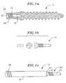
- FIG. 1 ais a side view and partial cross section of an embodiment of a pedicle screw according to a first embodiment of the invention.
- FIG. 1 bis a front and side view of an embodiment of a filler screw according to the first embodiment of the invention.
- FIG. 1 cis a side view of an embodiment of an alignment rod according to the first embodiment of the invention.
- FIG. 2 ais a front view of an embodiment of an alignment handle according to the first embodiment of the invention.
- FIG. 2 bis a side view of an embodiment of an alignment rod according to the first embodiment of the invention.
- FIG. 2 cis a front and side view of an embodiment of a filler screw according to the first embodiment of the invention.
- FIG. 2 dis a side view and partial cross section of an embodiment of a pedicle screw according to the first embodiment of the invention.
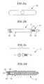
- FIG. 3 ais a side view of an embodiment of an alignment rod according to a second embodiment of the invention.
- FIG. 3 bis a side view and partial cross section of an embodiment of a pedicle screw according to the second embodiment of the invention.
- FIG. 3 cis a front and side view of an embodiment of a filler screw according to the second embodiment of the invention.
- FIG. 3 dis a front view of an embodiment of an alignment handle according to the second embodiment of the invention.
- FIG. 4 ais a side view and partial cross section of an embodiment of a pedicle screw according to a third embodiment of the invention.
- FIG. 4 bis a side view of an embodiment of an alignment rod according to the third embodiment of the invention.
- FIG. 4 cis a side view of a detail of the tip section of an embodiment of an alignment rod according to the third embodiment of the invention.
- FIG. 4 dis a side view of an embodiment of a filler screw according to the third embodiment of the invention.
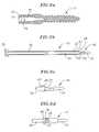
- FIG. 5 ais a side view and partial cross section of an embodiment of a pedicle screw according to a fourth embodiment of the invention.
- FIG. 5 bis a side view of an embodiment of an alignment rod according to the fourth embodiment of the invention.
- FIG. 5 cis a side view of a detail of the tip section of an embodiment of an alignment rod according to the fourth embodiment of the invention.
- FIG. 5 dis a side view of an embodiment of a filler screw according to the fourth embodiment of the invention.
- FIG. 6 ais a side view and partial cross section of an embodiment of a pedicle screw according to a fifth embodiment of the invention.
- FIG. 6 bis a side view of an embodiment of an alignment rod according to the fifth embodiment of the invention.
- FIG. 6 cis a side view of a detail of the tip section of an embodiment of an alignment rod according to the fifth embodiment of the invention in an engaged position with the pedicle screw.
- FIG. 6 dis a side view of a detail of the tip section of an embodiment of an alignment rod according to the fifth embodiment of the invention in a disengaged position with the pedicle screw.
- FIG. 7 ais a side view of an embodiment of fixation hardware according to the invention.
- FIG. 7 bis a top view of an embodiment of fixation hardware according to the invention.
- FIG. 7 cis a side view of an embodiment of fixation hardware according to the invention.
- FIG. 7 dis a top view of an embodiment of fixation hardware according to the invention.
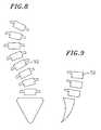
- FIG. 8is a schematic view of the deformity caused by Scoliosis.
- FIG. 9is a schematic view of the deformity caused by Spondylolisthesis.
- FIG. 10is a schematic view of the deformity cased by Kyphosis
- FIG. 11is a schematic view of the desired lordosis of a thoracic and a lumbar spine.
- FIGS. 12 a and 12 bare cross-sectional views of the placement of an embodiment of alignment rods into an embodiment of pedicle screws according to the invention.
- FIGS. 13 a and 13 bare schematic views of the manipulation and alignment of the spine utilizing an embodiment of the vertebral alignment system according to the invention.
- FIGS. 14 a and 14 bare schematic views of the point of rotation of the vertebral alignment system according to the invention.
- the present inventionrelates generally to a method and apparatus for aligning and fixing vertebral bodies. More specifically, the present invention is directed to a system and method to allow a surgeon to accurately manipulate and align vertebral bodies using removable alignment rods attached to pedicle screws and to enable the installation of fixation system hardware while the alignment rods are still in place.
- the vertebral alignment system of the current inventionconsists potentially of three main components: alignment rods 10 , cannulated pedicle screws 12 , and, optionally, filler plugs 14 .
- the alignment rod 10may be inserted and fixed within the pedicle screw 12 through any suitable means.
- the pedicle screw 12 as shown in FIGS. 1 a , 2 d , 3 b , 4 a and 5 ais partially cannulated to form a recess 16 and the recess is partially threaded 18 .
- the recess 16 of the pedicle screw 12comprises an identical, but reversed image of the alignment rod 10 , including threads 18 , a counterbore 20 and a flat 22 , which conform with that of the alignment rod 10 .
- the alignment rod 10may ( FIGS. 1 c , 2 b and 3 a ) or may not ( FIGS. 4 b and 5 b ) include a probe portion 24 at the tip of the alignment rod 10 .
- FIGS. 1 to 5all utilize a threaded mechanism to affix the alignment rod 10 within the recess 16 of the pedicle screw 12
- any fixation mechanismmay be utilized in the present invention.
- a compression fittingis utilized to affix the alignment rod 10 within the pedicle screw 12 .
- the alignment rod 10is cannulated and further comprises a slidable internal shaft 26 running the length of an alignment rod bore 27 , and a set of spring-loaded ball bearings 28 compressed within the body of the alignment rod 10 opposite a plurality of engaging openings 30 dimensioned such that a portion of the ball bearings 28 may be extended outside the body of the alignment rod 10 , but such that the remainder of each of the ball bearings 28 is fixedly held therein.
- the recess 16 of the pedicle screw 12comprises an identical, but reversed image of the alignment rod 10 , including a plurality of anchor receptacles 32 designed to receive the extended ball bearings 28 , a counterbore 20 and a flat 22 , which conform with that of the alignment rod 10 .
- this embodimentonly shows an alignment rod 10 including a probe portion 24 at its distal tip ( FIG. 6 b ), it should be understood that the alignment rod need not possess a probe.
- the alignment rod 10is positioned within the recess 16 of the pedicle screw 12 such that the ball bearings 28 are positioned opposite the anchor receptacles 32 .
- the internal shaft 26is then pressed into the alignment rod bore 27 such that the distal tip 34 of the shaft 26 presses against the inner surfaces of the ball bearings 28 forcing the ball bearings through the engaging openings 30 into the anchor receptacles 32 , thus fixing the alignment rod 10 within the pedicle screw 12 .
- the internal shaftmay further comprise a handle 35 and a locking mechanism for locking the compression fitting into place.
- any method of attaching the alignment rod within the pedicle screwmay be utilized, such as, for example a “bayonet” or “twist and lock” style connector such as that found in coaxial cable.
- the diameter and depth of the recessis designed to mate with that of the alignment rod threads and probe.
- the pedicle screwis preferably made from surgical grade titanium.
- the alignment rods 10are sized to allow fixation hardware to slide down the shaft 36 of the rod, which in turn allows the rod to remain in place until fixation hardware is placed and tightened.
- the rod 10includes threads 38 at the distal end, to allow for a T-Handle 40 , knob or alignment/stabilization frame to be attached. These threads 38 may also be used for the attachment of a screwdriver-type handle and be utilized for the installation of the pedicle screws 12 into the vertebral bodies.
- the rods 10also preferably have a connecting device, such as, a threaded portion or a compression fitting at the proximal end 42 , to mate with a cooperating fitting in the recess 16 of the pedicle screw 12 .
- a connecting devicesuch as, a threaded portion or a compression fitting at the proximal end 42 , to mate with a cooperating fitting in the recess 16 of the pedicle screw 12 .
- the rods 10may include a reduced diameter “probe” 24 extending beyond the connecting device.
- the probe 24allows for guidance of the alignment rod 10 into the pedicle screw 12 , provides additional rod strength and shifts the center of rotation further into the pedicle screw.
- the probe portion 24 of the rod 10may come in various lengths and diameters, as shown in FIGS. 1 and 2 versus FIG. 3 , and may or may not be tapered.
- the rodalso includes a conical tip and counterbore 43 between the connecting device and the handle portion of the rod, which mates with a similar counterbore and countersink 20 inside the pedicle screw 12 .
- This featureallows the rod 10 to seat positively to the pedicle screw 12 and provides additional support between the rod and screw.
- the rod 10also includes a flat 44 that provides for positive mating of the rod to the top of the pedicle screw.
- the rods 10will preferably vary in length between approximately, 4 and 12 inches although other sizes may be used. The selection of the rod length will be based upon the size of the patient and access to the surgical site.
- the filler plug 14is shaped identically to that of the end of the alignment rod 10 , but is much shorter.
- the plug 14is optionally placed into the pedicle screw 12 after the hardware has been tightened and the alignment rod 10 is removed.
- the alignment rod 10may also be severed immediately above the pedicle screw 12 , leaving the connector portion of the alignment rod 10 in place to act as a filler plug.
- the purpose of the filler plug 14is to provide additional screw strength, where the wall diameter has been reduced by the threads and probe recess.
- the filler plug 46is an optional component, but if used, will remain in the body with the pedicle screw implant. In those embodiments in which a separate filler plug 14 is attached to the pedicle screw 12 , the top of the filler plug will preferably have a flat or crossed recess, or have a hex or allen wrench style cap and will be installed and tightened with a similarly shaped surgical screwdriver.
- fixation hardwaresuch as, for example, that shown in FIGS. 7 a to 7 d , would also be provided to fix the spine into the desired alignment.
- the fixation hardwaremay comprise clamps 48 , which are designed to slide down the alignment rod 10 and mate with top or side of the cannulated pedicle screw at an external connector 46 , such as a external threaded portion of the screw as shown in FIGS.
- bendable fixation rods 50 or plateswhich run between the clamps on the various pedicle screws 12 attached either to different vertebral bodies 52 or at different points on a single vertebral body, and bolts, also designed to slide down the alignment rod and mate with the clamps such that the clamps 48 can be tightened onto and fix the fixation rods 50 into place.
- fixation hardwarecan be made of any suitable surgical material, such as, for example, stainless steel or titanium.
- two pedicle screws, two alignment rods and optionally, two filler plugs along with the appropriate fixation hardwareare used at each vertebral level.
- the number of components usedwould depend upon the spinal abnormality and the number of vertebral bodies, or levels to be aligned and fused. Examples of some common spinal abnormalities and normal spinal curvature are depicted in FIGS. 8 to 11 .
- Scoliosisin which, on a frontal or anterior view, the spine is angled or curved to the left or right, in some cases there may also be rotation of each individual segment to the left or right, as shown in FIG.
- FIG. 8Spondylolisthesis, most common in the lumbar region, in which a spinal segment has slipped forward over the underlying spinal segments, as shown in FIG. 9 ; and Kyphosis, or flat back syndrome, in which there is a loss of normal sagittal curvature in the lumbar spine, as depicted in FIG. 10.
- a normal spinal curvature or lordosisis depicted for comparison in FIG. 11 .
- FIGS. 12 a to 13 bshow a spinal alignment and fixation procedure utilizing the vertebral alignment apparatus and system described above.
- First a cannulated pedicle screw 12 according to the inventionwould be placed into the left and right pedicle 56 of the individual vertebra 52 .
- An alignment rod 10as described above, would then be inserted into the cannulated pedicle screw 12 and secured into the barrel of the cannulated pedicle screw. After this procedure, the alignment rod 10 extends above the screw 12 for a distance preferably between 4 to 12 inches, however any extension distance may be used depending upon the lever force the surgeon desires. Different size rods allow the surgeon to apply appropriate forces and lever to the spinal vertebral body.
- the alignment rods 10also have threaded ends 38 at the tops of the alignment rods permitting the surgeon to screw T-handles 40 (See FIGS. 12 a and 13 b ), or other appropriate manipulation devices, such as for example, alignment cages to the ends of the alignment rods.
- the alignment rods 10are then used to manipulate and align the vertebral body 52 to the desired angle and position according to known techniques, after which the position is verified by visualization and by X-ray.
- the surgeonhas the capacity to use the alignment rods 10 that are inserted into the hollow pedicle screw 12 because there is ligamentous laxity to each individual vertebral segment 52 . This ligamentous laxity allows the surgeon to manipulate the vertebral body.
- the surgeonwould rotate or tilt the vertebral body to correct scoliosis, pull or push the vertebral body to correct spondylolisthesis or retrolisthesis, tilt the vertebral body to improve sagittal alignment to promote lumbar lordosis and reduce flat back syndrome. Compression and distraction can also be applied to these points as well to promote correction of deformity.
- the vertebral alignment systemenables the surgeon to install the pedicle screw 12 by connecting the screwdriver handle 54 to the distal end of the alignment rod 10 , placing the pedicle screw 12 on the proximal end of the alignment rod 10 and implanting the pedicle screw (See FIGS. 12 b and 13 a ).
- the surgeonmay utilize the pedicle screw to navigate the spinal segment and correct the spinal deformity and not just as a point of attachment for the fixation hardware.
- the fixation hardwaremay, for example, comprise clamps 48 and rods 50 that mate with the cannulated pedicle screws 12 to allow for fixation of the desired vertebral alignment.
- the surgeonfirst aligns the vertebral bodies and then the clamps are placed over the alignment rods onto the pedicle screw or to the sides of the pedicle screws.
- Fixation rods or platesare then bent to the desired alignment and are then placed over the alignment rods or along the sides of the alignment rods and onto the clamps.
- Boltsare then secured onto these clamps, either over or at the side of the alignment rod.
- a specially designed cannulated screwdriveris slid down the shaft of the alignment rod and the bolts and clamps are then tightened over the fixation rods and the spine is then fixed, or held, in the alignment desired by the surgeon.
- the clamps and boltsare slid down the alignment rod to mate with the pedicle screw prior to alignment, but not tightened.
- the surgeonwould then manipulate the vertebral bodies into the proper, or desired, alignment and the fixation rods or plates would then be bent to the desired alignment and placed into the already positioned clamps and the bolts then secured.
- the surgeonmay alternatively use an iterative process to align the fixation rods or plates into position so that the vertebral bodies do not have an opportunity to slip into a misaligned conformation. In this iterative process, the fixation rods would be aligned and clamped multiple times before placing the spine into the proper conformation.
- a clamp, cage framework, surgical band or other suitable devicemay be utilized to hold the alignment rods in place once the surgeon has aligned them and while the fixation rods or plates are being adjusted and clamped to the pedicle screws.
- the screwdriveris then removed and the alignment rods are detached from the inside of the pedicle screw.
- a filler plugas described above, is then, optionally, inserted into the pedicle screw and tightened making the pedicle screw whole.
- the alignment rodmay also be severed immediately above the pedicle screw leaving a portion of the alignment rod in place to act as a filler plug. The operation site is then closed per normal surgical procedures.
- the alignment rod 10 of the present inventionis designed to fit into the pedicle screw at closely the approximate point 56 at which the center of rotation occurs in the vertebral segment 52 , as shown in FIGS. 14 a and 14 b .
- Thisallows the surgeon to apply force as a lever to the pedicle screw and use the lever of the pedicle screw to alter the vertebral body's position at its instantaneous center of rotation.
- this ability to mate the lever to the screw inside the pedicleallows the surgeon maximum ability to correct deformities.
- Lumbar lordosisrefers to the sagittal alignment of the spine in most disorders, due to degeneration of the disc or spondylolisthesis, lumbar lordosis is incrementally lost in the spine. Most current fusion methods do not improve lordosis. In fact, most fusion methods reduce lumbar lordosis.
- lordosisis promoted by placing the pedicle screws in the vertebral body and using the alignment rod to lever the vertebral bodies so the anterior margin of the vertebral body in question, i.e., L4 to the sacrum, increases in distance as the lever arms are used.
- Thisimproves the instantaneous center of rotation at each adjacent segment and reduces the stress of the vertebral body at the adjacent unfused segments. This appears to be most important for reducing stress at these levels and therefore reducing the potential for accelerated degeneration.
- the techniquerepresents a new advancement in the art of spinal surgical correction.
Landscapes
- Health & Medical Sciences (AREA)
- Orthopedic Medicine & Surgery (AREA)
- Neurology (AREA)
- Life Sciences & Earth Sciences (AREA)
- Surgery (AREA)
- Heart & Thoracic Surgery (AREA)
- Engineering & Computer Science (AREA)
- Biomedical Technology (AREA)
- Nuclear Medicine, Radiotherapy & Molecular Imaging (AREA)
- Medical Informatics (AREA)
- Molecular Biology (AREA)
- Animal Behavior & Ethology (AREA)
- General Health & Medical Sciences (AREA)
- Public Health (AREA)
- Veterinary Medicine (AREA)
- Surgical Instruments (AREA)
- Prostheses (AREA)
Abstract
Description
This application is based on provisional patent application Ser. No. 60/258,963, filed Dec. 29, 2000.
The present invention relates generally to a method and apparatus for alignment and fixation of vertebral bodies.
Pedicle screws allow spine surgeons to attach rods or plates to the thoracic and lumbar spine. This rigidly immobilizes the spine segments, promoting the bone graft to grow into a fusion, welding spinal segments into one solid unit, reducing pain and stabilizing deformity.
Three types of deformity that spinal surgeons attempt to correct with regularity are Scoliosis, Spondylolisthesis, and Kyphosis, or flat back syndrome. Actual manipulation of the spine and correction of these thoracic and lumbar deformities is accomplished by distraction or compression of the points of attachment to the spine. Points of attachments are generally either hooks underneath the lamina, hooks under the pedicles or pedicle screws.
While many different pedicle screws have been developed, presently the pedicle screw is not considered a navigational point of attachment to the spine, nor have the prior art systems allowed for the attachment of the fixation hardware without first removing the alignment rods or cages.
For example, Krag, U.S. Pat. No. 5,219,349, which is incorporated herein by reference, discloses a method of aligning vertebral bodies utilizing a stabilization cage, but does not provide a system for attaching the fixation hardware to the pedicle screw while the alignment cage is in place. Likewise, Bernstein, U.S. Pat. No. 6,004,322, which is incorporated herein by reference, discloses a cannulated pedicle screw design utilized to fix the spine, but also does not provide a system for attaching alignment rods or for attaching fixation hardware while such alignment rods are in place.
With these current systems, the surgeon must remove the alignment device prior to securing the fixation hardware, allowing the vertebral bodies time to return to their improper original alignment. Accordingly, a need exists for a system and apparatus that allows a surgeon to accurately manipulate and align vertebral bodies and to enable the installation of a fixation system while such alignment devices are still in place.
The present invention relates generally to a method and apparatus for aligning and fixing vertebral bodies. More specifically, the present invention is directed to a system and method to allow a surgeon to accurately manipulate and align vertebral bodies using removable alignment rods attached to pedicle screws and to enable the installation of fixation system hardware while the alignment rods are still in place.
In one embodiment, the vertebral alignment system of the current invention consists of three main components: alignment rods, cannulated pedicle screws, and, optionally, filler plugs. In this embodiment, two pedicle screws, two alignment rods and, optionally, two filler plugs are used at each vertebral level to be aligned. The number of components used would depend upon the spinal abnormality and the number of vertebral bodies, or levels to be aligned and fused.
In a preferred embodiment the vertebral alignment system of the present invention is designed to work on “top loading” fixation systems, such as the Advanced Spine Verigrip system, although other types of fixation systems could be used. A top loading system provides for the pedicle screw bolts and hardware to be installed from the top of the pedicle screw.
In another preferred embodiment, the invention is directed to a system for aligning vertebral bodies comprising a multiplicity of vertebral alignment components as described above attached at suitable points of attachment as determined by the deformity of the spine.
In still another embodiment, the invention is directed to a method for aligning vertebral bodies. The method comprises manipulating, aligning and fixing the spine using a vertebral alignment system as described above.
In all of the above embodiments, it is preferred that the components of the system are made from an orthopaedically suitable material, such as, for example, stainless steel or titanium.
These and other features and advantages of the present invention will be better understood by reference to the following detailed description when considered in conjunction with the accompanying drawings wherein:
The present invention relates generally to a method and apparatus for aligning and fixing vertebral bodies. More specifically, the present invention is directed to a system and method to allow a surgeon to accurately manipulate and align vertebral bodies using removable alignment rods attached to pedicle screws and to enable the installation of fixation system hardware while the alignment rods are still in place.
As shown inFIGS. 1 to6, the vertebral alignment system of the current invention consists potentially of three main components:alignment rods 10, cannulated pedicle screws12, and, optionally, filler plugs14. In these embodiments, thealignment rod 10 may be inserted and fixed within thepedicle screw 12 through any suitable means.
For example, in various embodiments, thepedicle screw 12 as shown inFIGS. 1 a,2d,3b,4aand5a, is partially cannulated to form arecess 16 and the recess is partially threaded18. In these embodiments, therecess 16 of thepedicle screw 12 comprises an identical, but reversed image of thealignment rod 10, includingthreads 18, acounterbore 20 and a flat22, which conform with that of thealignment rod 10. In these embodiments thealignment rod 10 may (FIGS. 1 c,2band3a) or may not (FIGS. 4 band5b) include aprobe portion 24 at the tip of thealignment rod 10.
Although the embodiments of the invention discussed inFIGS. 1 to5, above, all utilize a threaded mechanism to affix thealignment rod 10 within therecess 16 of thepedicle screw 12, it should be understood that any fixation mechanism may be utilized in the present invention. In one alternative embodiment, shown inFIG. 6 , a compression fitting is utilized to affix thealignment rod 10 within thepedicle screw 12. In this embodiment, thealignment rod 10 is cannulated and further comprises a slidableinternal shaft 26 running the length of an alignment rod bore27, and a set of spring-loadedball bearings 28 compressed within the body of thealignment rod 10 opposite a plurality of engagingopenings 30 dimensioned such that a portion of theball bearings 28 may be extended outside the body of thealignment rod 10, but such that the remainder of each of theball bearings 28 is fixedly held therein. In this embodiment, therecess 16 of thepedicle screw 12 comprises an identical, but reversed image of thealignment rod 10, including a plurality ofanchor receptacles 32 designed to receive theextended ball bearings 28, acounterbore 20 and a flat22, which conform with that of thealignment rod 10. Although this embodiment only shows analignment rod 10 including aprobe portion 24 at its distal tip (FIG. 6 b), it should be understood that the alignment rod need not possess a probe.
As shown inFIGS. 6 cand6d, during operation, thealignment rod 10 is positioned within therecess 16 of thepedicle screw 12 such that theball bearings 28 are positioned opposite theanchor receptacles 32. Theinternal shaft 26 is then pressed into the alignment rod bore27 such that thedistal tip 34 of theshaft 26 presses against the inner surfaces of theball bearings 28 forcing the ball bearings through the engagingopenings 30 into the anchor receptacles32, thus fixing thealignment rod 10 within thepedicle screw 12. In such an embodiment, the internal shaft may further comprise ahandle 35 and a locking mechanism for locking the compression fitting into place.
Although a compression fitting embodiment is discussed above, it should be understood that any method of attaching the alignment rod within the pedicle screw may be utilized, such as, for example a “bayonet” or “twist and lock” style connector such as that found in coaxial cable.
Regardless of the mechanism chosen to attach the alignment rod within the pedicle screw, the diameter and depth of the recess is designed to mate with that of the alignment rod threads and probe. In all of the above discussed embodiments, the pedicle screw is preferably made from surgical grade titanium.
Thealignment rods 10, as shown inFIGS. 1 c,2b,3a,4b,5band6bare sized to allow fixation hardware to slide down theshaft 36 of the rod, which in turn allows the rod to remain in place until fixation hardware is placed and tightened. Therod 10 includesthreads 38 at the distal end, to allow for a T-Handle 40, knob or alignment/stabilization frame to be attached. Thesethreads 38 may also be used for the attachment of a screwdriver-type handle and be utilized for the installation of the pedicle screws12 into the vertebral bodies. As discussed above, therods 10 also preferably have a connecting device, such as, a threaded portion or a compression fitting at theproximal end 42, to mate with a cooperating fitting in therecess 16 of thepedicle screw 12.
As discussed above, therods 10 may include a reduced diameter “probe”24 extending beyond the connecting device. In these embodiments, theprobe 24 allows for guidance of thealignment rod 10 into thepedicle screw 12, provides additional rod strength and shifts the center of rotation further into the pedicle screw. Theprobe portion 24 of therod 10 may come in various lengths and diameters, as shown inFIGS. 1 and 2 versusFIG. 3 , and may or may not be tapered.
The rod also includes a conical tip andcounterbore 43 between the connecting device and the handle portion of the rod, which mates with a similar counterbore and countersink20 inside thepedicle screw 12. This feature allows therod 10 to seat positively to thepedicle screw 12 and provides additional support between the rod and screw. Therod 10 also includes a flat44 that provides for positive mating of the rod to the top of the pedicle screw. Therods 10 will preferably vary in length between approximately,4 and12 inches although other sizes may be used. The selection of the rod length will be based upon the size of the patient and access to the surgical site.
Thefiller plug 14, as shown inFIGS. 1 b,2c,3c,4dand5d, is shaped identically to that of the end of thealignment rod 10, but is much shorter. Theplug 14 is optionally placed into thepedicle screw 12 after the hardware has been tightened and thealignment rod 10 is removed. At the option of the surgeon, thealignment rod 10 may also be severed immediately above thepedicle screw 12, leaving the connector portion of thealignment rod 10 in place to act as a filler plug. The purpose of thefiller plug 14 is to provide additional screw strength, where the wall diameter has been reduced by the threads and probe recess. Thefiller plug 46 is an optional component, but if used, will remain in the body with the pedicle screw implant. In those embodiments in which aseparate filler plug 14 is attached to thepedicle screw 12, the top of the filler plug will preferably have a flat or crossed recess, or have a hex or allen wrench style cap and will be installed and tightened with a similarly shaped surgical screwdriver.
In addition to these basic components, fixation hardware, such as, for example, that shown inFIGS. 7 ato7d, would also be provided to fix the spine into the desired alignment. The fixation hardware may compriseclamps 48, which are designed to slide down thealignment rod 10 and mate with top or side of the cannulated pedicle screw at anexternal connector 46, such as a external threaded portion of the screw as shown inFIGS. 1 a,2b,3b,4a,5a, and6a,bendable fixation rods 50 or plates, which run between the clamps on thevarious pedicle screws 12 attached either to differentvertebral bodies 52 or at different points on a single vertebral body, and bolts, also designed to slide down the alignment rod and mate with the clamps such that theclamps 48 can be tightened onto and fix thefixation rods 50 into place.
All of the above components, including the fixation hardware can be made of any suitable surgical material, such as, for example, stainless steel or titanium.
For an exemplary procedure, two pedicle screws, two alignment rods and optionally, two filler plugs along with the appropriate fixation hardware are used at each vertebral level. The number of components used would depend upon the spinal abnormality and the number of vertebral bodies, or levels to be aligned and fused. Examples of some common spinal abnormalities and normal spinal curvature are depicted inFIGS. 8 to11. Scoliosis, in which, on a frontal or anterior view, the spine is angled or curved to the left or right, in some cases there may also be rotation of each individual segment to the left or right, as shown inFIG. 8 ; Spondylolisthesis, most common in the lumbar region, in which a spinal segment has slipped forward over the underlying spinal segments, as shown inFIG. 9 ; and Kyphosis, or flat back syndrome, in which there is a loss of normal sagittal curvature in the lumbar spine, as depicted inFIG. 10. A normal spinal curvature or lordosis is depicted for comparison in FIG.11.
Alternatively, after thevertebral body 52 has been tapped and prepared for the implantation of thepedicle screw 12, the vertebral alignment system according to the present invention enables the surgeon to install thepedicle screw 12 by connecting the screwdriver handle54 to the distal end of thealignment rod 10, placing thepedicle screw 12 on the proximal end of thealignment rod 10 and implanting the pedicle screw (SeeFIGS. 12 band13a). Once thepedicle screw 12 is secured into thevertebral body 52, the surgeon may utilize the pedicle screw to navigate the spinal segment and correct the spinal deformity and not just as a point of attachment for the fixation hardware.
Once the surgeon has manipulated the vertebral bodies into the proper, or desired, alignment, the fixation hardware is slipped down the shaft of thealignment rod 10. The fixation hardware may, for example, comprise clamps48 androds 50 that mate with the cannulated pedicle screws12 to allow for fixation of the desired vertebral alignment. In one possible method, the surgeon first aligns the vertebral bodies and then the clamps are placed over the alignment rods onto the pedicle screw or to the sides of the pedicle screws. Fixation rods or plates are then bent to the desired alignment and are then placed over the alignment rods or along the sides of the alignment rods and onto the clamps. Bolts are then secured onto these clamps, either over or at the side of the alignment rod. A specially designed cannulated screwdriver is slid down the shaft of the alignment rod and the bolts and clamps are then tightened over the fixation rods and the spine is then fixed, or held, in the alignment desired by the surgeon.
In an alternative method, the clamps and bolts are slid down the alignment rod to mate with the pedicle screw prior to alignment, but not tightened. The surgeon would then manipulate the vertebral bodies into the proper, or desired, alignment and the fixation rods or plates would then be bent to the desired alignment and placed into the already positioned clamps and the bolts then secured. The surgeon may alternatively use an iterative process to align the fixation rods or plates into position so that the vertebral bodies do not have an opportunity to slip into a misaligned conformation. In this iterative process, the fixation rods would be aligned and clamped multiple times before placing the spine into the proper conformation. In another alternative method designed to prevent a misalignment of the aligned spine, a clamp, cage framework, surgical band or other suitable device may be utilized to hold the alignment rods in place once the surgeon has aligned them and while the fixation rods or plates are being adjusted and clamped to the pedicle screws.
Regardless of the method used to tighten the clamps on the fixation rods or plates, once the bolts have been tightened, the screwdriver is then removed and the alignment rods are detached from the inside of the pedicle screw. A filler plug, as described above, is then, optionally, inserted into the pedicle screw and tightened making the pedicle screw whole. Optionally the alignment rod may also be severed immediately above the pedicle screw leaving a portion of the alignment rod in place to act as a filler plug. The operation site is then closed per normal surgical procedures.
It is important to note that the instantaneous center of rotation of a spinal segment is in the posterior lateral corner of the vertebral body. Thealignment rod 10 of the present invention is designed to fit into the pedicle screw at closely the approximate point56 at which the center of rotation occurs in thevertebral segment 52, as shown inFIGS. 14 aand14b. This allows the surgeon to apply force as a lever to the pedicle screw and use the lever of the pedicle screw to alter the vertebral body's position at its instantaneous center of rotation. Predictably, this ability to mate the lever to the screw inside the pedicle allows the surgeon maximum ability to correct deformities.
One important example of this improved ability to correct deformities is realized in procedures involving correcting improper lumbar lordosis. Lumbar lordosis refers to the sagittal alignment of the spine in most disorders, due to degeneration of the disc or spondylolisthesis, lumbar lordosis is incrementally lost in the spine. Most current fusion methods do not improve lordosis. In fact, most fusion methods reduce lumbar lordosis.
There are many articles relating the deleterious effects of introgenic loss of lumbar lordosis after spinal instrumentation in the distal lumbar spine which leads to flat back syndrome. In short, there is a reciprocal balance between the curves of surgical lordosis, thoracic kyphosis and lumbar lordosis which allows efficient energy of absorption of the spinal column and increased efficiency of spinal musculature.
In effect, lordosis is promoted by placing the pedicle screws in the vertebral body and using the alignment rod to lever the vertebral bodies so the anterior margin of the vertebral body in question, i.e., L4 to the sacrum, increases in distance as the lever arms are used. This improves the instantaneous center of rotation at each adjacent segment and reduces the stress of the vertebral body at the adjacent unfused segments. This appears to be most important for reducing stress at these levels and therefore reducing the potential for accelerated degeneration. The technique represents a new advancement in the art of spinal surgical correction.
Although specific embodiments are disclosed herein, it is expected that persons skilled in the art can and will design alternative vertebral alignment systems that are within the scope of the following claims either literally or through substantial equivalents. For example, although the above discussion has described the use of an alignment rod and fixation hardware with a pedicle screw only, it should be understood that any device suitable for anchoring fixation hardware to a vertebral body, such as by way of example clamps, may be utilized with the present invention provided the anchor device is cannulated to allow the insertion of an alignment rod therein, and provided the body of the anchor device is so designed as to allow the top loading of fixation hardware down the alignment rod and onto the body of the anchor device.
Claims (12)
1. A vertebral alignment/fixation system comprising:
at least one elongated spinal adjustment device;
at least one vertebral alignment/fixation assembly comprising:
a screw comprising an elongated, partially cannulated shaft defining an axially arranged inner screw chamber and a screw axis, an axial opening being arranged at a proximal end of the shaft providing access to the inner screw chamber of the shaft and a tapered tip arranged at the distal end of the shaft, and wherein a distal end of the shaft is externally threaded for driving the screw into bone and wherein the proximal end of the shaft further comprises an anchor mechanism for attachment of at least one piece of fixation hardware, and
an alignment rod comprising an elongated shaft with an engaging portion arranged at the distal end of the shaft designed to insert into the axial opening and cooperatively engage the inner screw chamber of the shaft, and a elongated portion arranged at the proximal end of the shaft, the elongated portion of the alignment rod having an outer diameter less than or equal to that of the screw;
at least one piece of fixation attachment hardware designed to slide down the alignment rod and cooperatively engage the proximal anchor mechanism of the screw such that the at least one fixation attachment is fixedly attached thereto, the at least one fixation attachment further being designed to anchor the at least one spinal adjustment device in place.
2. A vertebral alignment/fixation system as described inclaim 1 , further comprising a filler plug, mateable with said inner screw chamber, the plug being designed to lockingly engage within and fill the inner screw chamber.
3. A vertebral alignment/fixation system as described inclaim 1 , wherein the spinal adjustment device is chosen from the group consisting of: plates, rods, clamps, crosslinks and wires.
4. A vertebral alignment/fixation system as described inclaim 1 , wherein the fixation attachment is chosen from the group consisting of: clamps, bolts and nuts.
5. A vertebral alignment/fixation system as described inclaim 1 , wherein the inner screw chamber of the shaft and the engaging portion of the alignment rod further comprise engagement mechanisms designed to cooperatively engage to lockingly hold the engaging portion of the alignment rod within the inner screw chamber of the screw shaft.
6. A vertebral alignment/fixation system as described inclaim 5 , wherein the engagement mechanism is selected from the group consisting of: a threaded fitting, a compression fitting, and a twist and lock mechanism.
7. A vertebral alignment/fixation assembly as described inclaim 1 , wherein the elongated portion of the alignment rod is threaded to receive a threaded attachment.
8. A vertebral alignment/fixation assembly as described inclaim 7 , wherein the elongated portion of the alignment rod is threaded to receive the threaded attachment consisting of either a T-type handle or a screwdriver-type handle.
9. A vertebral alignment/fixation system as described inclaim 1 , wherein the system components are made of stainless steel.
10. A vertebral alignment/fixation method comprising:
providing a vertebral alignment/fixation system as described inclaim 1 ;
driving the screw into a vertebral body;
inserting the alignment rod into the inner screw chamber of the screw;
aligning the vertebral body with the alignment rod;
sliding a piece of fixation attachment hardware down the alignment rod onto the screw;
tightening piece of fixation attachment hardware onto the screw; and
attaching a spinal adjustment device onto the fixation attachment hardware to fix the vertebral body in the chosen alignment.
11. A vertebral alignment/fixation method comprising utilizing a vertebral alignment/fixation system as described inclaim 1 to align at least one vertebral body.
12. A vertebral alignment/fixation method comprising utilizing a plurality of vertebral alignment assemblies as to align at least one vertebral body, wherein each of the vertebral alignment assemblies comprises:
a screw comprising an elongated, partially cannulated shaft defining an axially arranged inner screw chamber and a screw axis, an axial opening being arranged at a proximal end of the shaft providing access to the inner screw chamber of the shaft and a tapered tip arranged at a distal end of the shaft, and wherein the distal end of the shaft is externally threaded for driving the screw into bone and wherein the proximal end of the shaft further comprises an anchor mechanism for attachment of at least one piece of fixation attachment hardware; and
an alignment rod comprising an elongated shaft with an engaging portion arranged at a distal end of the shaft designed to insert into the axial opening and cooperatively engage the inner screw chamber of the shaft, and an elongated portion arranged at a proximal end of the shaft, the elongated portion of the alignment rod having an outer diameter less than or equal to that of the screw.
Priority Applications (1)
| Application Number | Priority Date | Filing Date | Title |
|---|---|---|---|
| US10/036,235US6964665B2 (en) | 2000-12-29 | 2001-12-27 | Vertebral alignment system |
Applications Claiming Priority (2)
| Application Number | Priority Date | Filing Date | Title |
|---|---|---|---|
| US25896300P | 2000-12-29 | 2000-12-29 | |
| US10/036,235US6964665B2 (en) | 2000-12-29 | 2001-12-27 | Vertebral alignment system |
Publications (2)
| Publication Number | Publication Date |
|---|---|
| US20020087159A1 US20020087159A1 (en) | 2002-07-04 |
| US6964665B2true US6964665B2 (en) | 2005-11-15 |
Family
ID=22982881
Family Applications (1)
| Application Number | Title | Priority Date | Filing Date |
|---|---|---|---|
| US10/036,235Expired - Fee RelatedUS6964665B2 (en) | 2000-12-29 | 2001-12-27 | Vertebral alignment system |
Country Status (3)
| Country | Link |
|---|---|
| US (1) | US6964665B2 (en) |
| AU (1) | AU2002248223A1 (en) |
| WO (1) | WO2002054935A2 (en) |
Cited By (120)
| Publication number | Priority date | Publication date | Assignee | Title |
|---|---|---|---|---|
| US20050113929A1 (en)* | 2000-02-16 | 2005-05-26 | Cragg Andrew H. | Spinal mobility preservation apparatus |
| US20060079898A1 (en)* | 2003-10-23 | 2006-04-13 | Trans1 Inc. | Spinal motion preservation assemblies |
| US20060155297A1 (en)* | 2003-10-23 | 2006-07-13 | Ainsworth Stephen D | Driver assembly for simultaneous axial delivery of spinal implants |
| US20060271050A1 (en)* | 2005-03-30 | 2006-11-30 | Gabriel Piza Vallespir | Instrumentation and methods for reducing spinal deformities |
| US20070168036A1 (en)* | 2003-10-23 | 2007-07-19 | Trans1 Inc. | Spinal motion preservation assemblies |
| US20070270843A1 (en)* | 2006-05-16 | 2007-11-22 | Wilfried Matthis | Longitudinal member for use in spinal or trauma surgery and stabilization device with such a longitudinal member |
| US20080004707A1 (en)* | 2003-10-23 | 2008-01-03 | Cragg Andrew H | Prosthetic nucleus apparatus and method |
| US20080154381A1 (en)* | 2006-12-21 | 2008-06-26 | Rob Gene Parrish | Intervertebral disc spacer |
| US20080154279A1 (en)* | 2006-12-22 | 2008-06-26 | Joerg Schumacher | Surgical instrument and osteosynthesis device |
| US20080154280A1 (en)* | 2006-12-22 | 2008-06-26 | Joerg Schumacher | Surgical instrument and osteosynthesis device |
| US20080262502A1 (en)* | 2006-10-24 | 2008-10-23 | Trans1, Inc. | Multi-membrane prosthetic nucleus |
| US20080269810A1 (en)* | 2007-04-12 | 2008-10-30 | Texas Scottish Rite Hospital For Children | Orthopedic Fastener for Stabilization and Fixation |
| US20080269805A1 (en)* | 2007-04-25 | 2008-10-30 | Warsaw Orthopedic, Inc. | Methods for correcting spinal deformities |
| US20090012563A1 (en)* | 2006-10-11 | 2009-01-08 | Nas Medical Technologies, Inc. | Spinal fixation devices and methods |
| US20090062857A1 (en)* | 2007-08-31 | 2009-03-05 | Ramsay Christopher L | Minimally invasive guide system |
| US20090062859A1 (en)* | 2007-08-31 | 2009-03-05 | Michael Mahoney | Method and system for securing a rod to a bone anchor with a connector |
| US20090062864A1 (en)* | 2007-08-31 | 2009-03-05 | Steven Ludwig | Offset connection bone anchor assembly |
| US20090062822A1 (en)* | 2007-08-31 | 2009-03-05 | Frasier William J | Adaptable clamping mechanism for coupling a spinal fixation element to a bone anchor |
| US20090062858A1 (en)* | 2007-08-31 | 2009-03-05 | Sara Dziedzic | Methods and instruments for approximating misaligned |
| US20090198273A1 (en)* | 2008-02-02 | 2009-08-06 | Texas Scottish Rite Hospital For Children | Pedicle Screw |
| US20090198279A1 (en)* | 2008-02-02 | 2009-08-06 | Texas Scottish Rite Hospital For Children | Spinal Rod Link Reducer |
| US7575600B2 (en) | 2004-09-29 | 2009-08-18 | Kyphon Sarl | Artificial vertebral disk replacement implant with translating articulation contact surface and method |
| US7628799B2 (en) | 2005-08-23 | 2009-12-08 | Aesculap Ag & Co. Kg | Rod to rod connector |
| US7662175B2 (en) | 2003-06-18 | 2010-02-16 | Jackson Roger P | Upload shank swivel head bone screw spinal implant |
| US20100076493A1 (en)* | 2004-02-17 | 2010-03-25 | Facet Solutions, Inc. | Facet Joint Replacement Instruments and Methods |
| US20100145462A1 (en)* | 2006-10-24 | 2010-06-10 | Trans1 Inc. | Preformed membranes for use in intervertebral disc spaces |
| US7744632B2 (en) | 2006-12-20 | 2010-06-29 | Aesculap Implant Systems, Inc. | Rod to rod connector |
| US7766915B2 (en) | 2004-02-27 | 2010-08-03 | Jackson Roger P | Dynamic fixation assemblies with inner core and outer coil-like member |
| US7776042B2 (en) | 2002-12-03 | 2010-08-17 | Trans1 Inc. | Methods and apparatus for provision of therapy to adjacent motion segments |
| US7875065B2 (en) | 2004-11-23 | 2011-01-25 | Jackson Roger P | Polyaxial bone screw with multi-part shank retainer and pressure insert |
| US7901437B2 (en) | 2007-01-26 | 2011-03-08 | Jackson Roger P | Dynamic stabilization member with molded connection |
| US7942911B2 (en) | 2007-05-16 | 2011-05-17 | Ortho Innovations, Llc | Polyaxial bone screw |
| US7942910B2 (en) | 2007-05-16 | 2011-05-17 | Ortho Innovations, Llc | Polyaxial bone screw |
| US7942909B2 (en) | 2009-08-13 | 2011-05-17 | Ortho Innovations, Llc | Thread-thru polyaxial pedicle screw system |
| US7947065B2 (en) | 2008-11-14 | 2011-05-24 | Ortho Innovations, Llc | Locking polyaxial ball and socket fastener |
| US7951173B2 (en) | 2007-05-16 | 2011-05-31 | Ortho Innovations, Llc | Pedicle screw implant system |
| US7951170B2 (en) | 2007-05-31 | 2011-05-31 | Jackson Roger P | Dynamic stabilization connecting member with pre-tensioned solid core |
| US7967850B2 (en) | 2003-06-18 | 2011-06-28 | Jackson Roger P | Polyaxial bone anchor with helical capture connection, insert and dual locking assembly |
| US8012177B2 (en) | 2007-02-12 | 2011-09-06 | Jackson Roger P | Dynamic stabilization assembly with frusto-conical connection |
| US20110276098A1 (en)* | 2010-05-05 | 2011-11-10 | Lutz Biedermann | Receiving part for receiving a rod for coupling the rod to a bone anchoring element, bone anchoring device, method and tool for assembling the same |
| US8057518B2 (en) | 2007-08-31 | 2011-11-15 | Depuy Spine, Inc. | Spanning connector for connecting a spinal fixation element and an offset bone anchor |
| US8066739B2 (en) | 2004-02-27 | 2011-11-29 | Jackson Roger P | Tool system for dynamic spinal implants |
| US8075603B2 (en) | 2008-11-14 | 2011-12-13 | Ortho Innovations, Llc | Locking polyaxial ball and socket fastener |
| US8092502B2 (en) | 2003-04-09 | 2012-01-10 | Jackson Roger P | Polyaxial bone screw with uploaded threaded shank and method of assembly and use |
| US8092500B2 (en) | 2007-05-01 | 2012-01-10 | Jackson Roger P | Dynamic stabilization connecting member with floating core, compression spacer and over-mold |
| US8100915B2 (en) | 2004-02-27 | 2012-01-24 | Jackson Roger P | Orthopedic implant rod reduction tool set and method |
| US8105368B2 (en) | 2005-09-30 | 2012-01-31 | Jackson Roger P | Dynamic stabilization connecting member with slitted core and outer sleeve |
| US8128667B2 (en) | 2002-09-06 | 2012-03-06 | Jackson Roger P | Anti-splay medical implant closure with multi-surface removal aperture |
| US8137386B2 (en) | 2003-08-28 | 2012-03-20 | Jackson Roger P | Polyaxial bone screw apparatus |
| US20120078374A1 (en)* | 2003-01-31 | 2012-03-29 | Spinalmotion, Inc. | Spinal midline indicator |
| US8152810B2 (en) | 2004-11-23 | 2012-04-10 | Jackson Roger P | Spinal fixation tool set and method |
| US20120095515A1 (en)* | 2010-09-23 | 2012-04-19 | Hamilton J Adam | Cannulated Screw and Core Assembly |
| US8197518B2 (en) | 2007-05-16 | 2012-06-12 | Ortho Innovations, Llc | Thread-thru polyaxial pedicle screw system |
| US8257407B2 (en)* | 2008-04-23 | 2012-09-04 | Aryan Henry E | Bone plate system and method |
| US8257398B2 (en) | 2003-06-18 | 2012-09-04 | Jackson Roger P | Polyaxial bone screw with cam capture |
| US8257402B2 (en) | 2002-09-06 | 2012-09-04 | Jackson Roger P | Closure for rod receiving orthopedic implant having left handed thread removal |
| US8273109B2 (en) | 2002-09-06 | 2012-09-25 | Jackson Roger P | Helical wound mechanically interlocking mating guide and advancement structure |
| US8292926B2 (en) | 2005-09-30 | 2012-10-23 | Jackson Roger P | Dynamic stabilization connecting member with elastic core and outer sleeve |
| US8308782B2 (en) | 2004-11-23 | 2012-11-13 | Jackson Roger P | Bone anchors with longitudinal connecting member engaging inserts and closures for fixation and optional angulation |
| US8353932B2 (en) | 2005-09-30 | 2013-01-15 | Jackson Roger P | Polyaxial bone anchor assembly with one-piece closure, pressure insert and plastic elongate member |
| US8366745B2 (en) | 2007-05-01 | 2013-02-05 | Jackson Roger P | Dynamic stabilization assembly having pre-compressed spacers with differential displacements |
| US8366753B2 (en) | 2003-06-18 | 2013-02-05 | Jackson Roger P | Polyaxial bone screw assembly with fixed retaining structure |
| US8377102B2 (en) | 2003-06-18 | 2013-02-19 | Roger P. Jackson | Polyaxial bone anchor with spline capture connection and lower pressure insert |
| US8377100B2 (en) | 2000-12-08 | 2013-02-19 | Roger P. Jackson | Closure for open-headed medical implant |
| US8398682B2 (en) | 2003-06-18 | 2013-03-19 | Roger P. Jackson | Polyaxial bone screw assembly |
| US8444681B2 (en) | 2009-06-15 | 2013-05-21 | Roger P. Jackson | Polyaxial bone anchor with pop-on shank, friction fit retainer and winged insert |
| US8475498B2 (en) | 2007-01-18 | 2013-07-02 | Roger P. Jackson | Dynamic stabilization connecting member with cord connection |
| US8545538B2 (en) | 2005-12-19 | 2013-10-01 | M. Samy Abdou | Devices and methods for inter-vertebral orthopedic device placement |
| US8556938B2 (en) | 2009-06-15 | 2013-10-15 | Roger P. Jackson | Polyaxial bone anchor with non-pivotable retainer and pop-on shank, some with friction fit |
| US8591515B2 (en) | 2004-11-23 | 2013-11-26 | Roger P. Jackson | Spinal fixation tool set and method |
| US8771319B2 (en) | 2012-04-16 | 2014-07-08 | Aesculap Implant Systems, Llc | Rod to rod cross connector |
| US8814913B2 (en) | 2002-09-06 | 2014-08-26 | Roger P Jackson | Helical guide and advancement flange with break-off extensions |
| US8814911B2 (en) | 2003-06-18 | 2014-08-26 | Roger P. Jackson | Polyaxial bone screw with cam connection and lock and release insert |
| US8828056B2 (en) | 2012-04-16 | 2014-09-09 | Aesculap Implant Systems, Llc | Rod to rod cross connector |
| US8845649B2 (en) | 2004-09-24 | 2014-09-30 | Roger P. Jackson | Spinal fixation tool set and method for rod reduction and fastener insertion |
| US8876868B2 (en) | 2002-09-06 | 2014-11-04 | Roger P. Jackson | Helical guide and advancement flange with radially loaded lip |
| US8911479B2 (en) | 2012-01-10 | 2014-12-16 | Roger P. Jackson | Multi-start closures for open implants |
| US8911477B2 (en) | 2007-10-23 | 2014-12-16 | Roger P. Jackson | Dynamic stabilization member with end plate support and cable core extension |
| US8936623B2 (en) | 2003-06-18 | 2015-01-20 | Roger P. Jackson | Polyaxial bone screw assembly |
| US8940024B2 (en) | 2007-07-31 | 2015-01-27 | Biedermann Technologies Gmbh & Co. Kg | Bone anchoring device |
| US8979904B2 (en) | 2007-05-01 | 2015-03-17 | Roger P Jackson | Connecting member with tensioned cord, low profile rigid sleeve and spacer with torsion control |
| US8998959B2 (en) | 2009-06-15 | 2015-04-07 | Roger P Jackson | Polyaxial bone anchors with pop-on shank, fully constrained friction fit retainer and lock and release insert |
| US9050139B2 (en) | 2004-02-27 | 2015-06-09 | Roger P. Jackson | Orthopedic implant rod reduction tool set and method |
| US9168069B2 (en) | 2009-06-15 | 2015-10-27 | Roger P. Jackson | Polyaxial bone anchor with pop-on shank and winged insert with lower skirt for engaging a friction fit retainer |
| US9198695B2 (en) | 2010-08-30 | 2015-12-01 | Zimmer Spine, Inc. | Polyaxial pedicle screw |
| US9216039B2 (en) | 2004-02-27 | 2015-12-22 | Roger P. Jackson | Dynamic spinal stabilization assemblies, tool set and method |
| US9216041B2 (en) | 2009-06-15 | 2015-12-22 | Roger P. Jackson | Spinal connecting members with tensioned cords and rigid sleeves for engaging compression inserts |
| US9345517B2 (en) | 2008-02-02 | 2016-05-24 | Globus Medical, Inc. | Pedicle screw having a removable rod coupling |
| US9414863B2 (en) | 2005-02-22 | 2016-08-16 | Roger P. Jackson | Polyaxial bone screw with spherical capture, compression insert and alignment and retention structures |
| US9451989B2 (en) | 2007-01-18 | 2016-09-27 | Roger P Jackson | Dynamic stabilization members with elastic and inelastic sections |
| US9453526B2 (en) | 2013-04-30 | 2016-09-27 | Degen Medical, Inc. | Bottom-loading anchor assembly |
| US9480517B2 (en) | 2009-06-15 | 2016-11-01 | Roger P. Jackson | Polyaxial bone anchor with pop-on shank, shank, friction fit retainer, winged insert and low profile edge lock |
| US9554832B2 (en) | 2007-05-18 | 2017-01-31 | Stryker European Holdings I, Llc | Apparatus and method for direct vertebral rotation |
| US9579126B2 (en) | 2008-02-02 | 2017-02-28 | Globus Medical, Inc. | Spinal rod link reducer |
| US9743957B2 (en) | 2004-11-10 | 2017-08-29 | Roger P. Jackson | Polyaxial bone screw with shank articulation pressure insert and method |
| US20170325862A1 (en)* | 2014-08-05 | 2017-11-16 | Medartis Holding Ag | Screw with insertion post |
| US9907574B2 (en) | 2008-08-01 | 2018-03-06 | Roger P. Jackson | Polyaxial bone anchors with pop-on shank, friction fit fully restrained retainer, insert and tool receiving features |
| US9980753B2 (en) | 2009-06-15 | 2018-05-29 | Roger P Jackson | pivotal anchor with snap-in-place insert having rotation blocking extensions |
| US10039578B2 (en) | 2003-12-16 | 2018-08-07 | DePuy Synthes Products, Inc. | Methods and devices for minimally invasive spinal fixation element placement |
| US10194951B2 (en) | 2005-05-10 | 2019-02-05 | Roger P. Jackson | Polyaxial bone anchor with compound articulation and pop-on shank |
| US10258382B2 (en) | 2007-01-18 | 2019-04-16 | Roger P. Jackson | Rod-cord dynamic connection assemblies with slidable bone anchor attachment members along the cord |
| US10299839B2 (en) | 2003-12-16 | 2019-05-28 | Medos International Sárl | Percutaneous access devices and bone anchor assemblies |
| US10363070B2 (en) | 2009-06-15 | 2019-07-30 | Roger P. Jackson | Pivotal bone anchor assemblies with pressure inserts and snap on articulating retainers |
| US10383660B2 (en) | 2007-05-01 | 2019-08-20 | Roger P. Jackson | Soft stabilization assemblies with pretensioned cords |
| US10543107B2 (en) | 2009-12-07 | 2020-01-28 | Samy Abdou | Devices and methods for minimally invasive spinal stabilization and instrumentation |
| US10548740B1 (en) | 2016-10-25 | 2020-02-04 | Samy Abdou | Devices and methods for vertebral bone realignment |
| US10575961B1 (en) | 2011-09-23 | 2020-03-03 | Samy Abdou | Spinal fixation devices and methods of use |
| US10667923B2 (en) | 2016-10-31 | 2020-06-02 | Warsaw Orthopedic, Inc. | Sacro-iliac joint implant system and method |
| US10695105B2 (en) | 2012-08-28 | 2020-06-30 | Samy Abdou | Spinal fixation devices and methods of use |
| US10729469B2 (en) | 2006-01-09 | 2020-08-04 | Roger P. Jackson | Flexible spinal stabilization assembly with spacer having off-axis core member |
| US10857003B1 (en) | 2015-10-14 | 2020-12-08 | Samy Abdou | Devices and methods for vertebral stabilization |
| US10918498B2 (en) | 2004-11-24 | 2021-02-16 | Samy Abdou | Devices and methods for inter-vertebral orthopedic device placement |
| US10973648B1 (en) | 2016-10-25 | 2021-04-13 | Samy Abdou | Devices and methods for vertebral bone realignment |
| US11006982B2 (en) | 2012-02-22 | 2021-05-18 | Samy Abdou | Spinous process fixation devices and methods of use |
| US11173040B2 (en) | 2012-10-22 | 2021-11-16 | Cogent Spine, LLC | Devices and methods for spinal stabilization and instrumentation |
| US11179248B2 (en) | 2018-10-02 | 2021-11-23 | Samy Abdou | Devices and methods for spinal implantation |
| US11344354B2 (en) | 2019-09-09 | 2022-05-31 | Warsaw Orthopedic, Inc. | Surgical instrument and method |
| US11419642B2 (en) | 2003-12-16 | 2022-08-23 | Medos International Sarl | Percutaneous access devices and bone anchor assemblies |
| US11564812B2 (en) | 2019-09-09 | 2023-01-31 | Warsaw Orthopedic, Inc. | Surgical instrument and method |
| US12383311B2 (en) | 2010-05-14 | 2025-08-12 | Roger P. Jackson | Pivotal bone anchor assembly and method for use thereof |
Families Citing this family (34)
| Publication number | Priority date | Publication date | Assignee | Title |
|---|---|---|---|---|
| US7833250B2 (en) | 2004-11-10 | 2010-11-16 | Jackson Roger P | Polyaxial bone screw with helically wound capture connection |
| WO2002076317A1 (en)* | 2001-03-27 | 2002-10-03 | Ferree Bret A | Hinged anterior thoracic/lumbar plate |
| AU2002950443A0 (en)* | 2002-07-26 | 2002-09-12 | Graeme Brazenor Pty Limited | Spinal implant |
| US7377923B2 (en) | 2003-05-22 | 2008-05-27 | Alphatec Spine, Inc. | Variable angle spinal screw assembly |
| US6986771B2 (en) | 2003-05-23 | 2006-01-17 | Globus Medical, Inc. | Spine stabilization system |
| US7137985B2 (en)* | 2003-09-24 | 2006-11-21 | N Spine, Inc. | Marking and guidance method and system for flexible fixation of a spine |
| US20050203513A1 (en)* | 2003-09-24 | 2005-09-15 | Tae-Ahn Jahng | Spinal stabilization device |
| US8979900B2 (en) | 2003-09-24 | 2015-03-17 | DePuy Synthes Products, LLC | Spinal stabilization device |
| US7815665B2 (en)* | 2003-09-24 | 2010-10-19 | N Spine, Inc. | Adjustable spinal stabilization system |
| US7763052B2 (en)* | 2003-12-05 | 2010-07-27 | N Spine, Inc. | Method and apparatus for flexible fixation of a spine |
| DE102004048938B4 (en)* | 2004-10-07 | 2015-04-02 | Synthes Gmbh | Device for the dynamic stabilization of vertebral bodies |
| US8926672B2 (en) | 2004-11-10 | 2015-01-06 | Roger P. Jackson | Splay control closure for open bone anchor |
| WO2006057837A1 (en) | 2004-11-23 | 2006-06-01 | Jackson Roger P | Spinal fixation tool attachment structure |
| US8163261B2 (en)* | 2005-04-05 | 2012-04-24 | Voltaix, Llc | System and method for making Si2H6 and higher silanes |
| US20070010818A1 (en)* | 2005-07-06 | 2007-01-11 | Stone Howard A | Surgical system for joints |
| US20070168039A1 (en)* | 2006-01-13 | 2007-07-19 | Sdgi Holdings, Inc. | Materials, devices and methods for treating multiple spinal regions including vertebral body and endplate regions |
| US20070173821A1 (en)* | 2006-01-13 | 2007-07-26 | Sdgi Holdings, Inc. | Materials, devices, and methods for treating multiple spinal regions including the posterior and spinous process regions |
| US20070173820A1 (en)* | 2006-01-13 | 2007-07-26 | Sdgi Holdings, Inc. | Materials, devices, and methods for treating multiple spinal regions including the anterior region |
| WO2008003047A2 (en)* | 2006-06-28 | 2008-01-03 | Synthes (U.S.A.) | Dynamic fixation system |
| CN102525623B (en) | 2006-12-10 | 2015-04-29 | 帕拉迪格脊骨有限责任公司 | Posterior functionally dynamic stabilization system |
| EP2178451A2 (en)* | 2007-08-07 | 2010-04-28 | Synthes GmbH | Dynamic cable system |
| WO2010078029A1 (en) | 2008-12-17 | 2010-07-08 | Synthes Usa, Llc | Posterior spine dynamic stabilizer |
| US9668771B2 (en) | 2009-06-15 | 2017-06-06 | Roger P Jackson | Soft stabilization assemblies with off-set connector |
| US11229457B2 (en) | 2009-06-15 | 2022-01-25 | Roger P. Jackson | Pivotal bone anchor assembly with insert tool deployment |
| US20110009906A1 (en)* | 2009-07-13 | 2011-01-13 | Zimmer Spine, Inc. | Vertebral stabilization transition connector |
| US8657856B2 (en)* | 2009-08-28 | 2014-02-25 | Pioneer Surgical Technology, Inc. | Size transition spinal rod |
| US8911478B2 (en) | 2012-11-21 | 2014-12-16 | Roger P. Jackson | Splay control closure for open bone anchor |
| US10058354B2 (en) | 2013-01-28 | 2018-08-28 | Roger P. Jackson | Pivotal bone anchor assembly with frictional shank head seating surfaces |
| US8852239B2 (en) | 2013-02-15 | 2014-10-07 | Roger P Jackson | Sagittal angle screw with integral shank and receiver |
| US9566092B2 (en) | 2013-10-29 | 2017-02-14 | Roger P. Jackson | Cervical bone anchor with collet retainer and outer locking sleeve |
| US9717533B2 (en) | 2013-12-12 | 2017-08-01 | Roger P. Jackson | Bone anchor closure pivot-splay control flange form guide and advancement structure |
| US9451993B2 (en) | 2014-01-09 | 2016-09-27 | Roger P. Jackson | Bi-radial pop-on cervical bone anchor |
| US10064658B2 (en) | 2014-06-04 | 2018-09-04 | Roger P. Jackson | Polyaxial bone anchor with insert guides |
| US9597119B2 (en) | 2014-06-04 | 2017-03-21 | Roger P. Jackson | Polyaxial bone anchor with polymer sleeve |
Citations (37)
| Publication number | Priority date | Publication date | Assignee | Title |
|---|---|---|---|---|
| US3579831A (en)* | 1969-03-05 | 1971-05-25 | Irving J Stevens | Bone implant |
| US3741205A (en)* | 1971-06-14 | 1973-06-26 | K Markolf | Bone fixation plate |
| US4463753A (en) | 1980-01-04 | 1984-08-07 | Gustilo Ramon B | Compression bone screw |
| US4763644A (en)* | 1984-02-28 | 1988-08-16 | Webb Peter J | Spinal fixation |
| US5000165A (en) | 1989-05-15 | 1991-03-19 | Watanabe Robert S | Lumbar spine rod fixation system |
| US5030220A (en) | 1990-03-29 | 1991-07-09 | Advanced Spine Fixation Systems Incorporated | Spine fixation system |
| US5100405A (en) | 1990-09-07 | 1992-03-31 | Mclaren Alexander C | Locking cap for medical implants |
| US5139499A (en) | 1989-02-06 | 1992-08-18 | American Cyanamid Company | Screw and driver |
| US5196016A (en)* | 1991-03-11 | 1993-03-23 | Institut Straumann Ag | Auxiliary means and method for fastening a capping on bone tissue or the like |
| US5217497A (en) | 1990-07-04 | 1993-06-08 | Mehdian Seyed M H | Apparatus for use in the treatment of spinal disorders |
| US5219349A (en) | 1991-02-15 | 1993-06-15 | Howmedica, Inc. | Spinal fixator reduction frame |
| US5306275A (en) | 1992-12-31 | 1994-04-26 | Bryan Donald W | Lumbar spine fixation apparatus and method |
| US5409486A (en)* | 1993-04-16 | 1995-04-25 | Phoenix Surgical Products, Inc. | Double threaded arthrodesis screw |
| US5425733A (en)* | 1992-02-19 | 1995-06-20 | Arthrex, Inc. | Interference screw with rounded back end and cannulated sheath for endosteal fixation of ligaments |
| US5437671A (en) | 1992-03-10 | 1995-08-01 | Zimmer, Inc. | Perpendicular rod connector for spinal fixation device |
| US5591165A (en) | 1992-11-09 | 1997-01-07 | Sofamor, S.N.C. | Apparatus and method for spinal fixation and correction of spinal deformities |
| US5607425A (en) | 1993-10-08 | 1997-03-04 | Rogozinski; Chaim | Apparatus, method and system for the treatment of spinal conditions |
| US5674224A (en)* | 1994-11-18 | 1997-10-07 | Howell; Stephen M. | Bone mulch screw assembly for endosteal fixation of soft tissue grafts and method for using same |
| US5713900A (en)* | 1996-05-31 | 1998-02-03 | Acromed Corporation | Apparatus for retaining bone portions in a desired spatial relationship |
| US5743912A (en)* | 1995-08-23 | 1998-04-28 | Biomat | Upper femoral epiphysis osteosynthesis implant |
| US5885299A (en) | 1994-09-15 | 1999-03-23 | Surgical Dynamics, Inc. | Apparatus and method for implant insertion |
| US5947965A (en) | 1992-12-31 | 1999-09-07 | Bryan; Donald W. | Spinal fixation apparatus and method |
| US5971987A (en) | 1998-09-18 | 1999-10-26 | Ethicon, Inc. | Biocompatible absorbable polymer fastener and driver for use in surgical procedures |
| US5984922A (en) | 1993-07-09 | 1999-11-16 | Mckay; Douglas William | Spinal fixation device and method |
| US5989250A (en) | 1996-10-24 | 1999-11-23 | Spinal Concepts, Inc. | Method and apparatus for spinal fixation |
| US6001098A (en) | 1997-01-17 | 1999-12-14 | Howmedica Gmbh | Connecting element for spinal stabilizing system |
| US6004322A (en) | 1994-10-25 | 1999-12-21 | Sdgi Holdings, Inc. | Modular pedicle screw system |
| US6015409A (en) | 1994-05-25 | 2000-01-18 | Sdgi Holdings, Inc. | Apparatus and method for spinal fixation and correction of spinal deformities |
| US6050997A (en) | 1999-01-25 | 2000-04-18 | Mullane; Thomas S. | Spinal fixation system |
| US6056753A (en) | 1998-07-13 | 2000-05-02 | Jackson; Roger P. | Set screw for use with osteosynthesis apparatus |
| US6074423A (en) | 1998-11-02 | 2000-06-13 | Lawson; Kevin Jon | Safer more X-ray transparent spinal implant |
| US6077267A (en) | 1992-04-28 | 2000-06-20 | Huene; Donald R. | Absorbable bone screw and tool for its insertion |
| US6110173A (en) | 1998-09-15 | 2000-08-29 | Advanced Spine Fixation Systems, Inc. | Transverse connector for spinal fixation systems |
| US6126662A (en)* | 1998-10-09 | 2000-10-03 | Carmichael; Robert P. | Bone implant |
| US6132430A (en) | 1996-10-24 | 2000-10-17 | Spinal Concepts, Inc. | Spinal fixation system |
| US6139548A (en) | 1995-10-30 | 2000-10-31 | Spinal Concepts, Inc. | Sliding shaft variable length cross-link device for use with dual rod apparatus |
| US6423062B2 (en)* | 2000-02-18 | 2002-07-23 | Albert Enayati | Bioabsorbable pin for external bone fixation |
- 2001
- 2001-12-27WOPCT/US2001/049558patent/WO2002054935A2/ennot_activeApplication Discontinuation
- 2001-12-27AUAU2002248223Apatent/AU2002248223A1/ennot_activeAbandoned
- 2001-12-27USUS10/036,235patent/US6964665B2/ennot_activeExpired - Fee Related
Patent Citations (37)
| Publication number | Priority date | Publication date | Assignee | Title |
|---|---|---|---|---|
| US3579831A (en)* | 1969-03-05 | 1971-05-25 | Irving J Stevens | Bone implant |
| US3741205A (en)* | 1971-06-14 | 1973-06-26 | K Markolf | Bone fixation plate |
| US4463753A (en) | 1980-01-04 | 1984-08-07 | Gustilo Ramon B | Compression bone screw |
| US4763644A (en)* | 1984-02-28 | 1988-08-16 | Webb Peter J | Spinal fixation |
| US5139499A (en) | 1989-02-06 | 1992-08-18 | American Cyanamid Company | Screw and driver |
| US5000165A (en) | 1989-05-15 | 1991-03-19 | Watanabe Robert S | Lumbar spine rod fixation system |
| US5030220A (en) | 1990-03-29 | 1991-07-09 | Advanced Spine Fixation Systems Incorporated | Spine fixation system |
| US5217497A (en) | 1990-07-04 | 1993-06-08 | Mehdian Seyed M H | Apparatus for use in the treatment of spinal disorders |
| US5100405A (en) | 1990-09-07 | 1992-03-31 | Mclaren Alexander C | Locking cap for medical implants |
| US5219349A (en) | 1991-02-15 | 1993-06-15 | Howmedica, Inc. | Spinal fixator reduction frame |
| US5196016A (en)* | 1991-03-11 | 1993-03-23 | Institut Straumann Ag | Auxiliary means and method for fastening a capping on bone tissue or the like |
| US5425733A (en)* | 1992-02-19 | 1995-06-20 | Arthrex, Inc. | Interference screw with rounded back end and cannulated sheath for endosteal fixation of ligaments |
| US5437671A (en) | 1992-03-10 | 1995-08-01 | Zimmer, Inc. | Perpendicular rod connector for spinal fixation device |
| US6077267A (en) | 1992-04-28 | 2000-06-20 | Huene; Donald R. | Absorbable bone screw and tool for its insertion |
| US5591165A (en) | 1992-11-09 | 1997-01-07 | Sofamor, S.N.C. | Apparatus and method for spinal fixation and correction of spinal deformities |
| US5947965A (en) | 1992-12-31 | 1999-09-07 | Bryan; Donald W. | Spinal fixation apparatus and method |
| US5306275A (en) | 1992-12-31 | 1994-04-26 | Bryan Donald W | Lumbar spine fixation apparatus and method |
| US5409486A (en)* | 1993-04-16 | 1995-04-25 | Phoenix Surgical Products, Inc. | Double threaded arthrodesis screw |
| US5984922A (en) | 1993-07-09 | 1999-11-16 | Mckay; Douglas William | Spinal fixation device and method |
| US5607425A (en) | 1993-10-08 | 1997-03-04 | Rogozinski; Chaim | Apparatus, method and system for the treatment of spinal conditions |
| US6015409A (en) | 1994-05-25 | 2000-01-18 | Sdgi Holdings, Inc. | Apparatus and method for spinal fixation and correction of spinal deformities |
| US5885299A (en) | 1994-09-15 | 1999-03-23 | Surgical Dynamics, Inc. | Apparatus and method for implant insertion |
| US6004322A (en) | 1994-10-25 | 1999-12-21 | Sdgi Holdings, Inc. | Modular pedicle screw system |
| US5674224A (en)* | 1994-11-18 | 1997-10-07 | Howell; Stephen M. | Bone mulch screw assembly for endosteal fixation of soft tissue grafts and method for using same |
| US5743912A (en)* | 1995-08-23 | 1998-04-28 | Biomat | Upper femoral epiphysis osteosynthesis implant |
| US6139548A (en) | 1995-10-30 | 2000-10-31 | Spinal Concepts, Inc. | Sliding shaft variable length cross-link device for use with dual rod apparatus |
| US5713900A (en)* | 1996-05-31 | 1998-02-03 | Acromed Corporation | Apparatus for retaining bone portions in a desired spatial relationship |
| US5989250A (en) | 1996-10-24 | 1999-11-23 | Spinal Concepts, Inc. | Method and apparatus for spinal fixation |
| US6132430A (en) | 1996-10-24 | 2000-10-17 | Spinal Concepts, Inc. | Spinal fixation system |
| US6001098A (en) | 1997-01-17 | 1999-12-14 | Howmedica Gmbh | Connecting element for spinal stabilizing system |
| US6056753A (en) | 1998-07-13 | 2000-05-02 | Jackson; Roger P. | Set screw for use with osteosynthesis apparatus |
| US6110173A (en) | 1998-09-15 | 2000-08-29 | Advanced Spine Fixation Systems, Inc. | Transverse connector for spinal fixation systems |
| US5971987A (en) | 1998-09-18 | 1999-10-26 | Ethicon, Inc. | Biocompatible absorbable polymer fastener and driver for use in surgical procedures |
| US6126662A (en)* | 1998-10-09 | 2000-10-03 | Carmichael; Robert P. | Bone implant |
| US6074423A (en) | 1998-11-02 | 2000-06-13 | Lawson; Kevin Jon | Safer more X-ray transparent spinal implant |
| US6050997A (en) | 1999-01-25 | 2000-04-18 | Mullane; Thomas S. | Spinal fixation system |
| US6423062B2 (en)* | 2000-02-18 | 2002-07-23 | Albert Enayati | Bioabsorbable pin for external bone fixation |
Non-Patent Citations (1)
| Title |
|---|
| GMReis Implantes advertisement, "EXACTO for Polyaxial Pedicle Pin Stabilization System", no date. |
Cited By (225)
| Publication number | Priority date | Publication date | Assignee | Title |
|---|---|---|---|---|
| US7905905B2 (en) | 2000-02-16 | 2011-03-15 | Trans1, Inc. | Spinal mobility preservation apparatus |
| US20050113919A1 (en)* | 2000-02-16 | 2005-05-26 | Cragg Andrew H. | Prosthetic nucleus apparatus |
| US20050113929A1 (en)* | 2000-02-16 | 2005-05-26 | Cragg Andrew H. | Spinal mobility preservation apparatus |
| US7662173B2 (en)* | 2000-02-16 | 2010-02-16 | Transl, Inc. | Spinal mobility preservation apparatus |
| US7717958B2 (en) | 2000-02-16 | 2010-05-18 | Trans1, Inc. | Prosthetic nucleus apparatus |
| US7905908B2 (en) | 2000-02-16 | 2011-03-15 | Trans1, Inc. | Spinal mobility preservation method |
| US8377100B2 (en) | 2000-12-08 | 2013-02-19 | Roger P. Jackson | Closure for open-headed medical implant |
| US8591552B2 (en) | 2002-09-06 | 2013-11-26 | Roger P. Jackson | Anti-splay medical implant closure with multi-surface removal aperture |
| US8282673B2 (en) | 2002-09-06 | 2012-10-09 | Jackson Roger P | Anti-splay medical implant closure with multi-surface removal aperture |
| US8128667B2 (en) | 2002-09-06 | 2012-03-06 | Jackson Roger P | Anti-splay medical implant closure with multi-surface removal aperture |
| US8876868B2 (en) | 2002-09-06 | 2014-11-04 | Roger P. Jackson | Helical guide and advancement flange with radially loaded lip |
| US8257402B2 (en) | 2002-09-06 | 2012-09-04 | Jackson Roger P | Closure for rod receiving orthopedic implant having left handed thread removal |
| US8814913B2 (en) | 2002-09-06 | 2014-08-26 | Roger P Jackson | Helical guide and advancement flange with break-off extensions |
| US8273109B2 (en) | 2002-09-06 | 2012-09-25 | Jackson Roger P | Helical wound mechanically interlocking mating guide and advancement structure |
| US8167947B2 (en) | 2002-12-03 | 2012-05-01 | Trans1 Inc. | Methods for push distraction and for provision of therapy to adjacent motion segments |
| US8523918B2 (en) | 2002-12-03 | 2013-09-03 | Baxano Surgical, Inc. | Therapy to adjacent motion segments |
| US7776042B2 (en) | 2002-12-03 | 2010-08-17 | Trans1 Inc. | Methods and apparatus for provision of therapy to adjacent motion segments |
| US8328847B2 (en) | 2002-12-03 | 2012-12-11 | Trans1 Inc. | Assemblies for provision of therapy to motion segments |
| US20120078374A1 (en)* | 2003-01-31 | 2012-03-29 | Spinalmotion, Inc. | Spinal midline indicator |
| US10952777B2 (en) | 2003-04-09 | 2021-03-23 | Roger P. Jackson | Pivotal bone screw assembly with receiver having threaded open channel and lower opening |
| US8540753B2 (en) | 2003-04-09 | 2013-09-24 | Roger P. Jackson | Polyaxial bone screw with uploaded threaded shank and method of assembly and use |
| US8092502B2 (en) | 2003-04-09 | 2012-01-10 | Jackson Roger P | Polyaxial bone screw with uploaded threaded shank and method of assembly and use |
| US8814911B2 (en) | 2003-06-18 | 2014-08-26 | Roger P. Jackson | Polyaxial bone screw with cam connection and lock and release insert |
| US9144444B2 (en) | 2003-06-18 | 2015-09-29 | Roger P Jackson | Polyaxial bone anchor with helical capture connection, insert and dual locking assembly |
| US8366753B2 (en) | 2003-06-18 | 2013-02-05 | Jackson Roger P | Polyaxial bone screw assembly with fixed retaining structure |
| USRE46431E1 (en) | 2003-06-18 | 2017-06-13 | Roger P Jackson | Polyaxial bone anchor with helical capture connection, insert and dual locking assembly |
| US7967850B2 (en) | 2003-06-18 | 2011-06-28 | Jackson Roger P | Polyaxial bone anchor with helical capture connection, insert and dual locking assembly |
| US8398682B2 (en) | 2003-06-18 | 2013-03-19 | Roger P. Jackson | Polyaxial bone screw assembly |
| US7662175B2 (en) | 2003-06-18 | 2010-02-16 | Jackson Roger P | Upload shank swivel head bone screw spinal implant |
| US8936623B2 (en) | 2003-06-18 | 2015-01-20 | Roger P. Jackson | Polyaxial bone screw assembly |
| US8377102B2 (en) | 2003-06-18 | 2013-02-19 | Roger P. Jackson | Polyaxial bone anchor with spline capture connection and lower pressure insert |
| US8636769B2 (en) | 2003-06-18 | 2014-01-28 | Roger P. Jackson | Polyaxial bone screw with shank-retainer insert capture |
| US8257398B2 (en) | 2003-06-18 | 2012-09-04 | Jackson Roger P | Polyaxial bone screw with cam capture |
| US8257396B2 (en) | 2003-06-18 | 2012-09-04 | Jackson Roger P | Polyaxial bone screw with shank-retainer inset capture |
| US8137386B2 (en) | 2003-08-28 | 2012-03-20 | Jackson Roger P | Polyaxial bone screw apparatus |
| US20070167951A1 (en)* | 2003-10-23 | 2007-07-19 | Trans1 Inc. | Methods and tools for delivery of spinal motion preservation assemblies |
| US20060155297A1 (en)* | 2003-10-23 | 2006-07-13 | Ainsworth Stephen D | Driver assembly for simultaneous axial delivery of spinal implants |
| US8038680B2 (en) | 2003-10-23 | 2011-10-18 | Trans1 Inc. | Drivers for inserts to bone anchors |
| US20080195156A1 (en)* | 2003-10-23 | 2008-08-14 | Trans1 Inc. | Methods for Deploying Spinal Motion Preservation Assemblies |
| US20080004707A1 (en)* | 2003-10-23 | 2008-01-03 | Cragg Andrew H | Prosthetic nucleus apparatus and method |
| US7601171B2 (en) | 2003-10-23 | 2009-10-13 | Trans1 Inc. | Spinal motion preservation assemblies |
| US20070168036A1 (en)* | 2003-10-23 | 2007-07-19 | Trans1 Inc. | Spinal motion preservation assemblies |
| US7776068B2 (en) | 2003-10-23 | 2010-08-17 | Trans1 Inc. | Spinal motion preservation assemblies |
| US7938836B2 (en) | 2003-10-23 | 2011-05-10 | Trans1, Inc. | Driver assembly for simultaneous axial delivery of spinal implants |
| US20060079898A1 (en)* | 2003-10-23 | 2006-04-13 | Trans1 Inc. | Spinal motion preservation assemblies |
| US10039578B2 (en) | 2003-12-16 | 2018-08-07 | DePuy Synthes Products, Inc. | Methods and devices for minimally invasive spinal fixation element placement |
| US11419642B2 (en) | 2003-12-16 | 2022-08-23 | Medos International Sarl | Percutaneous access devices and bone anchor assemblies |
| US11426216B2 (en) | 2003-12-16 | 2022-08-30 | DePuy Synthes Products, Inc. | Methods and devices for minimally invasive spinal fixation element placement |
| US10299839B2 (en) | 2003-12-16 | 2019-05-28 | Medos International Sárl | Percutaneous access devices and bone anchor assemblies |
| US20100076493A1 (en)* | 2004-02-17 | 2010-03-25 | Facet Solutions, Inc. | Facet Joint Replacement Instruments and Methods |
| US8900270B2 (en)* | 2004-02-17 | 2014-12-02 | Gmedelaware 2 Llc | Facet joint replacement instruments and methods |
| US8394133B2 (en) | 2004-02-27 | 2013-03-12 | Roger P. Jackson | Dynamic fixation assemblies with inner core and outer coil-like member |
| US7766915B2 (en) | 2004-02-27 | 2010-08-03 | Jackson Roger P | Dynamic fixation assemblies with inner core and outer coil-like member |
| US8162948B2 (en) | 2004-02-27 | 2012-04-24 | Jackson Roger P | Orthopedic implant rod reduction tool set and method |
| US9050139B2 (en) | 2004-02-27 | 2015-06-09 | Roger P. Jackson | Orthopedic implant rod reduction tool set and method |
| US8377067B2 (en) | 2004-02-27 | 2013-02-19 | Roger P. Jackson | Orthopedic implant rod reduction tool set and method |
| US8292892B2 (en) | 2004-02-27 | 2012-10-23 | Jackson Roger P | Orthopedic implant rod reduction tool set and method |
| US8066739B2 (en) | 2004-02-27 | 2011-11-29 | Jackson Roger P | Tool system for dynamic spinal implants |
| US9216039B2 (en) | 2004-02-27 | 2015-12-22 | Roger P. Jackson | Dynamic spinal stabilization assemblies, tool set and method |
| US9055978B2 (en) | 2004-02-27 | 2015-06-16 | Roger P. Jackson | Orthopedic implant rod reduction tool set and method |
| US8900272B2 (en) | 2004-02-27 | 2014-12-02 | Roger P Jackson | Dynamic fixation assemblies with inner core and outer coil-like member |
| US9918751B2 (en) | 2004-02-27 | 2018-03-20 | Roger P. Jackson | Tool system for dynamic spinal implants |
| US8100915B2 (en) | 2004-02-27 | 2012-01-24 | Jackson Roger P | Orthopedic implant rod reduction tool set and method |
| US8894657B2 (en) | 2004-02-27 | 2014-11-25 | Roger P. Jackson | Tool system for dynamic spinal implants |
| US8845649B2 (en) | 2004-09-24 | 2014-09-30 | Roger P. Jackson | Spinal fixation tool set and method for rod reduction and fastener insertion |
| US7575600B2 (en) | 2004-09-29 | 2009-08-18 | Kyphon Sarl | Artificial vertebral disk replacement implant with translating articulation contact surface and method |
| US9743957B2 (en) | 2004-11-10 | 2017-08-29 | Roger P. Jackson | Polyaxial bone screw with shank articulation pressure insert and method |
| US10039577B2 (en) | 2004-11-23 | 2018-08-07 | Roger P Jackson | Bone anchor receiver with horizontal radiused tool attachment structures and parallel planar outer surfaces |
| US8308782B2 (en) | 2004-11-23 | 2012-11-13 | Jackson Roger P | Bone anchors with longitudinal connecting member engaging inserts and closures for fixation and optional angulation |
| US8152810B2 (en) | 2004-11-23 | 2012-04-10 | Jackson Roger P | Spinal fixation tool set and method |
| US9211150B2 (en) | 2004-11-23 | 2015-12-15 | Roger P. Jackson | Spinal fixation tool set and method |
| US8591515B2 (en) | 2004-11-23 | 2013-11-26 | Roger P. Jackson | Spinal fixation tool set and method |
| US8840652B2 (en) | 2004-11-23 | 2014-09-23 | Roger P. Jackson | Bone anchors with longitudinal connecting member engaging inserts and closures for fixation and optional angulation |
| US9320545B2 (en) | 2004-11-23 | 2016-04-26 | Roger P. Jackson | Polyaxial bone screw with multi-part shank retainer and pressure insert |
| US11389214B2 (en) | 2004-11-23 | 2022-07-19 | Roger P. Jackson | Spinal fixation tool set and method |
| US7875065B2 (en) | 2004-11-23 | 2011-01-25 | Jackson Roger P | Polyaxial bone screw with multi-part shank retainer and pressure insert |
| US9629669B2 (en) | 2004-11-23 | 2017-04-25 | Roger P. Jackson | Spinal fixation tool set and method |
| US8273089B2 (en) | 2004-11-23 | 2012-09-25 | Jackson Roger P | Spinal fixation tool set and method |
| US11992423B2 (en) | 2004-11-24 | 2024-05-28 | Samy Abdou | Devices and methods for inter-vertebral orthopedic device placement |
| US11096799B2 (en) | 2004-11-24 | 2021-08-24 | Samy Abdou | Devices and methods for inter-vertebral orthopedic device placement |
| US10918498B2 (en) | 2004-11-24 | 2021-02-16 | Samy Abdou | Devices and methods for inter-vertebral orthopedic device placement |
| US9414863B2 (en) | 2005-02-22 | 2016-08-16 | Roger P. Jackson | Polyaxial bone screw with spherical capture, compression insert and alignment and retention structures |
| US10076361B2 (en) | 2005-02-22 | 2018-09-18 | Roger P. Jackson | Polyaxial bone screw with spherical capture, compression and alignment and retention structures |
| USRE47551E1 (en) | 2005-02-22 | 2019-08-06 | Roger P. Jackson | Polyaxial bone screw with spherical capture, compression insert and alignment and retention structures |
| US8147524B2 (en) | 2005-03-30 | 2012-04-03 | Warsaw Orthopedic, Inc. | Instrumentation and methods for reducing spinal deformities |
| US20060271050A1 (en)* | 2005-03-30 | 2006-11-30 | Gabriel Piza Vallespir | Instrumentation and methods for reducing spinal deformities |
| US10194951B2 (en) | 2005-05-10 | 2019-02-05 | Roger P. Jackson | Polyaxial bone anchor with compound articulation and pop-on shank |
| US11234745B2 (en) | 2005-07-14 | 2022-02-01 | Roger P. Jackson | Polyaxial bone screw assembly with partially spherical screw head and twist in place pressure insert |
| US7628799B2 (en) | 2005-08-23 | 2009-12-08 | Aesculap Ag & Co. Kg | Rod to rod connector |
| US8613760B2 (en) | 2005-09-30 | 2013-12-24 | Roger P. Jackson | Dynamic stabilization connecting member with slitted core and outer sleeve |
| US8696711B2 (en) | 2005-09-30 | 2014-04-15 | Roger P. Jackson | Polyaxial bone anchor assembly with one-piece closure, pressure insert and plastic elongate member |
| US8353932B2 (en) | 2005-09-30 | 2013-01-15 | Jackson Roger P | Polyaxial bone anchor assembly with one-piece closure, pressure insert and plastic elongate member |
| US8292926B2 (en) | 2005-09-30 | 2012-10-23 | Jackson Roger P | Dynamic stabilization connecting member with elastic core and outer sleeve |
| US8591560B2 (en) | 2005-09-30 | 2013-11-26 | Roger P. Jackson | Dynamic stabilization connecting member with elastic core and outer sleeve |
| US8105368B2 (en) | 2005-09-30 | 2012-01-31 | Jackson Roger P | Dynamic stabilization connecting member with slitted core and outer sleeve |
| US8545538B2 (en) | 2005-12-19 | 2013-10-01 | M. Samy Abdou | Devices and methods for inter-vertebral orthopedic device placement |
| US10729469B2 (en) | 2006-01-09 | 2020-08-04 | Roger P. Jackson | Flexible spinal stabilization assembly with spacer having off-axis core member |
| US20070270843A1 (en)* | 2006-05-16 | 2007-11-22 | Wilfried Matthis | Longitudinal member for use in spinal or trauma surgery and stabilization device with such a longitudinal member |
| US8216274B2 (en)* | 2006-05-16 | 2012-07-10 | Biedermann Technologies Gmbh & Co. Kg | Longitudinal member for use in spinal or trauma surgery and stabilization device with such a longitudinal member |
| US20090012563A1 (en)* | 2006-10-11 | 2009-01-08 | Nas Medical Technologies, Inc. | Spinal fixation devices and methods |
| US20100137991A1 (en)* | 2006-10-24 | 2010-06-03 | Trans1, Inc. | Prosthetic nucleus with a preformed membrane |
| US20100145462A1 (en)* | 2006-10-24 | 2010-06-10 | Trans1 Inc. | Preformed membranes for use in intervertebral disc spaces |
| US8088147B2 (en) | 2006-10-24 | 2012-01-03 | Trans1 Inc. | Multi-membrane prosthetic nucleus |
| US20080262502A1 (en)* | 2006-10-24 | 2008-10-23 | Trans1, Inc. | Multi-membrane prosthetic nucleus |
| US8328846B2 (en) | 2006-10-24 | 2012-12-11 | Trans1 Inc. | Prosthetic nucleus with a preformed membrane |
| US7744632B2 (en) | 2006-12-20 | 2010-06-29 | Aesculap Implant Systems, Inc. | Rod to rod connector |
| US20080154381A1 (en)* | 2006-12-21 | 2008-06-26 | Rob Gene Parrish | Intervertebral disc spacer |
| US20080177389A1 (en)* | 2006-12-21 | 2008-07-24 | Rob Gene Parrish | Intervertebral disc spacer |
| US8951300B2 (en) | 2006-12-21 | 2015-02-10 | Rob Gene Parrish | Intervertebral disc spacer |
| US20080154280A1 (en)* | 2006-12-22 | 2008-06-26 | Joerg Schumacher | Surgical instrument and osteosynthesis device |
| US7922731B2 (en) | 2006-12-22 | 2011-04-12 | Aesculap Ag | Surgical instrument and osteosynthesis device |
| US7998144B2 (en) | 2006-12-22 | 2011-08-16 | Aesculap Ag | Surgical instrument and osteosynthesis device |
| US20080154279A1 (en)* | 2006-12-22 | 2008-06-26 | Joerg Schumacher | Surgical instrument and osteosynthesis device |
| US10258382B2 (en) | 2007-01-18 | 2019-04-16 | Roger P. Jackson | Rod-cord dynamic connection assemblies with slidable bone anchor attachment members along the cord |
| US8475498B2 (en) | 2007-01-18 | 2013-07-02 | Roger P. Jackson | Dynamic stabilization connecting member with cord connection |
| US9451989B2 (en) | 2007-01-18 | 2016-09-27 | Roger P Jackson | Dynamic stabilization members with elastic and inelastic sections |
| US10470801B2 (en) | 2007-01-18 | 2019-11-12 | Roger P. Jackson | Dynamic spinal stabilization with rod-cord longitudinal connecting members |
| US10792074B2 (en) | 2007-01-22 | 2020-10-06 | Roger P. Jackson | Pivotal bone anchor assemly with twist-in-place friction fit insert |
| US7901437B2 (en) | 2007-01-26 | 2011-03-08 | Jackson Roger P | Dynamic stabilization member with molded connection |
| US9101404B2 (en) | 2007-01-26 | 2015-08-11 | Roger P. Jackson | Dynamic stabilization connecting member with molded connection |
| US8012177B2 (en) | 2007-02-12 | 2011-09-06 | Jackson Roger P | Dynamic stabilization assembly with frusto-conical connection |
| US8506599B2 (en) | 2007-02-12 | 2013-08-13 | Roger P. Jackson | Dynamic stabilization assembly with frusto-conical connection |
| US10603077B2 (en) | 2007-04-12 | 2020-03-31 | Globus Medical, Inc. | Orthopedic fastener for stabilization and fixation |
| US20080269810A1 (en)* | 2007-04-12 | 2008-10-30 | Texas Scottish Rite Hospital For Children | Orthopedic Fastener for Stabilization and Fixation |
| US10092327B2 (en) | 2007-04-25 | 2018-10-09 | Warsaw Orthopedic, Inc. | Methods for correcting spinal deformities |
| US20080269805A1 (en)* | 2007-04-25 | 2008-10-30 | Warsaw Orthopedic, Inc. | Methods for correcting spinal deformities |
| US9289243B2 (en) | 2007-04-25 | 2016-03-22 | Warsaw Orthopedic, Inc. | Methods for correcting spinal deformities |
| US8979904B2 (en) | 2007-05-01 | 2015-03-17 | Roger P Jackson | Connecting member with tensioned cord, low profile rigid sleeve and spacer with torsion control |
| US10383660B2 (en) | 2007-05-01 | 2019-08-20 | Roger P. Jackson | Soft stabilization assemblies with pretensioned cords |
| US8366745B2 (en) | 2007-05-01 | 2013-02-05 | Jackson Roger P | Dynamic stabilization assembly having pre-compressed spacers with differential displacements |
| US8092500B2 (en) | 2007-05-01 | 2012-01-10 | Jackson Roger P | Dynamic stabilization connecting member with floating core, compression spacer and over-mold |
| US7951173B2 (en) | 2007-05-16 | 2011-05-31 | Ortho Innovations, Llc | Pedicle screw implant system |
| US7942910B2 (en) | 2007-05-16 | 2011-05-17 | Ortho Innovations, Llc | Polyaxial bone screw |
| US7942911B2 (en) | 2007-05-16 | 2011-05-17 | Ortho Innovations, Llc | Polyaxial bone screw |
| US8197518B2 (en) | 2007-05-16 | 2012-06-12 | Ortho Innovations, Llc | Thread-thru polyaxial pedicle screw system |
| US11963699B2 (en) | 2007-05-18 | 2024-04-23 | Stryker European Operations Holdings Llc | Apparatus and method for direct vertebral rotation |
| US11172965B2 (en) | 2007-05-18 | 2021-11-16 | Stryker European Operations Holdings Llc | Apparatus and method for direct vertebral rotation |
| US9974578B2 (en) | 2007-05-18 | 2018-05-22 | Stryker European Holdings I, Llc | Apparatus and method for direct vertebral rotation |
| US9554832B2 (en) | 2007-05-18 | 2017-01-31 | Stryker European Holdings I, Llc | Apparatus and method for direct vertebral rotation |
| US7951170B2 (en) | 2007-05-31 | 2011-05-31 | Jackson Roger P | Dynamic stabilization connecting member with pre-tensioned solid core |
| US9289246B2 (en) | 2007-07-31 | 2016-03-22 | Biedermann Technologies Gmbh & Co. Kg | Bone anchoring device |
| US8940024B2 (en) | 2007-07-31 | 2015-01-27 | Biedermann Technologies Gmbh & Co. Kg | Bone anchoring device |
| US8894690B2 (en) | 2007-08-31 | 2014-11-25 | DePuy Synthes Products, LLC | Offset connection bone anchor assembly |
| US20090062858A1 (en)* | 2007-08-31 | 2009-03-05 | Sara Dziedzic | Methods and instruments for approximating misaligned |
| US20090062822A1 (en)* | 2007-08-31 | 2009-03-05 | Frasier William J | Adaptable clamping mechanism for coupling a spinal fixation element to a bone anchor |
| US8512343B2 (en) | 2007-08-31 | 2013-08-20 | DePuy Synthes Products, LLC | Methods and instruments for approximating misaligned vertebra |
| US8025682B2 (en) | 2007-08-31 | 2011-09-27 | Depuy Spine, Inc. | Method and system for securing a rod to a bone anchor with a connector |
| US8057518B2 (en) | 2007-08-31 | 2011-11-15 | Depuy Spine, Inc. | Spanning connector for connecting a spinal fixation element and an offset bone anchor |
| US20090062864A1 (en)* | 2007-08-31 | 2009-03-05 | Steven Ludwig | Offset connection bone anchor assembly |
| US20090062859A1 (en)* | 2007-08-31 | 2009-03-05 | Michael Mahoney | Method and system for securing a rod to a bone anchor with a connector |
| US8900237B2 (en) | 2007-08-31 | 2014-12-02 | DePuy Synthes Products, LLC | Minimally invasive guide system |
| US20090062857A1 (en)* | 2007-08-31 | 2009-03-05 | Ramsay Christopher L | Minimally invasive guide system |
| US8911477B2 (en) | 2007-10-23 | 2014-12-16 | Roger P. Jackson | Dynamic stabilization member with end plate support and cable core extension |
| US9526526B2 (en) | 2008-02-02 | 2016-12-27 | Globus Medical, Inc. | Pedicle screw |
| US11426206B2 (en) | 2008-02-02 | 2022-08-30 | Globus Medical, Inc. | Pedicle screw having a removable rod coupling |
| US9345517B2 (en) | 2008-02-02 | 2016-05-24 | Globus Medical, Inc. | Pedicle screw having a removable rod coupling |
| US12364516B2 (en) | 2008-02-02 | 2025-07-22 | Globus Medical Inc. | Pedicle screw having a removable rod coupling |
| US9579126B2 (en) | 2008-02-02 | 2017-02-28 | Globus Medical, Inc. | Spinal rod link reducer |
| US9050141B2 (en) | 2008-02-02 | 2015-06-09 | Texas Scottish Rite Hospital For Children | Pedicle screw |
| US20090198279A1 (en)* | 2008-02-02 | 2009-08-06 | Texas Scottish Rite Hospital For Children | Spinal Rod Link Reducer |
| US9408641B2 (en) | 2008-02-02 | 2016-08-09 | Globus Medical, Inc. | Spinal rod link reducer |
| US9526527B2 (en) | 2008-02-02 | 2016-12-27 | Globus Medical, Inc. | Pedicle screw having a removable rod coupling |
| US20090198273A1 (en)* | 2008-02-02 | 2009-08-06 | Texas Scottish Rite Hospital For Children | Pedicle Screw |
| US8257407B2 (en)* | 2008-04-23 | 2012-09-04 | Aryan Henry E | Bone plate system and method |
| US9907574B2 (en) | 2008-08-01 | 2018-03-06 | Roger P. Jackson | Polyaxial bone anchors with pop-on shank, friction fit fully restrained retainer, insert and tool receiving features |
| US8465530B2 (en) | 2008-11-14 | 2013-06-18 | Ortho Innovations, Llc | Locking polyaxial ball and socket fastener |
| US7947065B2 (en) | 2008-11-14 | 2011-05-24 | Ortho Innovations, Llc | Locking polyaxial ball and socket fastener |
| US8075603B2 (en) | 2008-11-14 | 2011-12-13 | Ortho Innovations, Llc | Locking polyaxial ball and socket fastener |
| US9168069B2 (en) | 2009-06-15 | 2015-10-27 | Roger P. Jackson | Polyaxial bone anchor with pop-on shank and winged insert with lower skirt for engaging a friction fit retainer |
| US9216041B2 (en) | 2009-06-15 | 2015-12-22 | Roger P. Jackson | Spinal connecting members with tensioned cords and rigid sleeves for engaging compression inserts |
| US9504496B2 (en) | 2009-06-15 | 2016-11-29 | Roger P. Jackson | Polyaxial bone anchor with pop-on shank, friction fit retainer and winged insert |
| US9980753B2 (en) | 2009-06-15 | 2018-05-29 | Roger P Jackson | pivotal anchor with snap-in-place insert having rotation blocking extensions |
| US9918745B2 (en) | 2009-06-15 | 2018-03-20 | Roger P. Jackson | Polyaxial bone anchor with pop-on shank and winged insert with friction fit compressive collet |
| US10363070B2 (en) | 2009-06-15 | 2019-07-30 | Roger P. Jackson | Pivotal bone anchor assemblies with pressure inserts and snap on articulating retainers |
| US9393047B2 (en) | 2009-06-15 | 2016-07-19 | Roger P. Jackson | Polyaxial bone anchor with pop-on shank and friction fit retainer with low profile edge lock |
| US9480517B2 (en) | 2009-06-15 | 2016-11-01 | Roger P. Jackson | Polyaxial bone anchor with pop-on shank, shank, friction fit retainer, winged insert and low profile edge lock |
| US8998959B2 (en) | 2009-06-15 | 2015-04-07 | Roger P Jackson | Polyaxial bone anchors with pop-on shank, fully constrained friction fit retainer and lock and release insert |
| US8556938B2 (en) | 2009-06-15 | 2013-10-15 | Roger P. Jackson | Polyaxial bone anchor with non-pivotable retainer and pop-on shank, some with friction fit |
| US8444681B2 (en) | 2009-06-15 | 2013-05-21 | Roger P. Jackson | Polyaxial bone anchor with pop-on shank, friction fit retainer and winged insert |
| US7942909B2 (en) | 2009-08-13 | 2011-05-17 | Ortho Innovations, Llc | Thread-thru polyaxial pedicle screw system |
| US10857004B2 (en) | 2009-12-07 | 2020-12-08 | Samy Abdou | Devices and methods for minimally invasive spinal stabilization and instrumentation |
| US10945861B2 (en) | 2009-12-07 | 2021-03-16 | Samy Abdou | Devices and methods for minimally invasive spinal stabilization and instrumentation |
| US10610380B2 (en) | 2009-12-07 | 2020-04-07 | Samy Abdou | Devices and methods for minimally invasive spinal stabilization and instrumentation |
| US11918486B2 (en) | 2009-12-07 | 2024-03-05 | Samy Abdou | Devices and methods for minimally invasive spinal stabilization and instrumentation |
| US10543107B2 (en) | 2009-12-07 | 2020-01-28 | Samy Abdou | Devices and methods for minimally invasive spinal stabilization and instrumentation |
| US9566091B2 (en) | 2010-05-05 | 2017-02-14 | Biedermann Technologies Gmbh & Co. Kg | Method and tool for assembling a bone anchoring device |
| US9381043B2 (en) | 2010-05-05 | 2016-07-05 | Biedermann Technologies Gmbh & Co. Kg | Insert for a tool for assembling a bone anchoring device and tool for assembling a bone anchoring device |
| US20110276098A1 (en)* | 2010-05-05 | 2011-11-10 | Lutz Biedermann | Receiving part for receiving a rod for coupling the rod to a bone anchoring element, bone anchoring device, method and tool for assembling the same |
| US12383311B2 (en) | 2010-05-14 | 2025-08-12 | Roger P. Jackson | Pivotal bone anchor assembly and method for use thereof |
| US9198695B2 (en) | 2010-08-30 | 2015-12-01 | Zimmer Spine, Inc. | Polyaxial pedicle screw |
| US12082851B2 (en) | 2010-08-30 | 2024-09-10 | Zimmer Spine, Inc. | Polyaxial pedicle screw |
| US9636148B2 (en) | 2010-08-30 | 2017-05-02 | Zimmer Spine, Inc. | Polyaxial pedicle screw |
| US10925646B2 (en) | 2010-08-30 | 2021-02-23 | Zimmer Spine, Inc. | Polyaxial pedicle screw |
| US10945766B2 (en) | 2010-08-30 | 2021-03-16 | Zimmer Spine, Inc. | Polyaxial pedicle screw |
| US10182844B2 (en) | 2010-08-30 | 2019-01-22 | Zimmer Spine, Inc. | Polyaxial pedicle screw |
| US11166751B2 (en) | 2010-08-30 | 2021-11-09 | Zimmer Spine, Inc. | Polyaxial pedicle screw |
| US20120095515A1 (en)* | 2010-09-23 | 2012-04-19 | Hamilton J Adam | Cannulated Screw and Core Assembly |
| US12167973B2 (en) | 2011-09-23 | 2024-12-17 | Samy Abdou | Spinal fixation devices and methods of use |
| US11517449B2 (en) | 2011-09-23 | 2022-12-06 | Samy Abdou | Spinal fixation devices and methods of use |
| US11324608B2 (en) | 2011-09-23 | 2022-05-10 | Samy Abdou | Spinal fixation devices and methods of use |
| US10575961B1 (en) | 2011-09-23 | 2020-03-03 | Samy Abdou | Spinal fixation devices and methods of use |
| US8911479B2 (en) | 2012-01-10 | 2014-12-16 | Roger P. Jackson | Multi-start closures for open implants |
| US11839413B2 (en) | 2012-02-22 | 2023-12-12 | Samy Abdou | Spinous process fixation devices and methods of use |
| US11006982B2 (en) | 2012-02-22 | 2021-05-18 | Samy Abdou | Spinous process fixation devices and methods of use |
| US8828056B2 (en) | 2012-04-16 | 2014-09-09 | Aesculap Implant Systems, Llc | Rod to rod cross connector |
| US8771319B2 (en) | 2012-04-16 | 2014-07-08 | Aesculap Implant Systems, Llc | Rod to rod cross connector |
| US10695105B2 (en) | 2012-08-28 | 2020-06-30 | Samy Abdou | Spinal fixation devices and methods of use |
| US11559336B2 (en) | 2012-08-28 | 2023-01-24 | Samy Abdou | Spinal fixation devices and methods of use |
| US11918483B2 (en) | 2012-10-22 | 2024-03-05 | Cogent Spine Llc | Devices and methods for spinal stabilization and instrumentation |
| US11173040B2 (en) | 2012-10-22 | 2021-11-16 | Cogent Spine, LLC | Devices and methods for spinal stabilization and instrumentation |
| US9453526B2 (en) | 2013-04-30 | 2016-09-27 | Degen Medical, Inc. | Bottom-loading anchor assembly |
| US10582959B2 (en)* | 2014-08-05 | 2020-03-10 | Medartis Holding Ag | Screw with insertion post |
| US20170325862A1 (en)* | 2014-08-05 | 2017-11-16 | Medartis Holding Ag | Screw with insertion post |
| US11246718B2 (en) | 2015-10-14 | 2022-02-15 | Samy Abdou | Devices and methods for vertebral stabilization |
| US10857003B1 (en) | 2015-10-14 | 2020-12-08 | Samy Abdou | Devices and methods for vertebral stabilization |
| US11752008B1 (en) | 2016-10-25 | 2023-09-12 | Samy Abdou | Devices and methods for vertebral bone realignment |
| US11058548B1 (en) | 2016-10-25 | 2021-07-13 | Samy Abdou | Devices and methods for vertebral bone realignment |
| US11259935B1 (en) | 2016-10-25 | 2022-03-01 | Samy Abdou | Devices and methods for vertebral bone realignment |
| US10973648B1 (en) | 2016-10-25 | 2021-04-13 | Samy Abdou | Devices and methods for vertebral bone realignment |
| US10548740B1 (en) | 2016-10-25 | 2020-02-04 | Samy Abdou | Devices and methods for vertebral bone realignment |
| US10744000B1 (en) | 2016-10-25 | 2020-08-18 | Samy Abdou | Devices and methods for vertebral bone realignment |
| US10667923B2 (en) | 2016-10-31 | 2020-06-02 | Warsaw Orthopedic, Inc. | Sacro-iliac joint implant system and method |
| US11179248B2 (en) | 2018-10-02 | 2021-11-23 | Samy Abdou | Devices and methods for spinal implantation |
| US11564812B2 (en) | 2019-09-09 | 2023-01-31 | Warsaw Orthopedic, Inc. | Surgical instrument and method |
| US11344354B2 (en) | 2019-09-09 | 2022-05-31 | Warsaw Orthopedic, Inc. | Surgical instrument and method |
Also Published As
| Publication number | Publication date |
|---|---|
| AU2002248223A1 (en) | 2002-07-24 |
| WO2002054935A2 (en) | 2002-07-18 |
| WO2002054935A3 (en) | 2003-03-13 |
| US20020087159A1 (en) | 2002-07-04 |
Similar Documents
| Publication | Publication Date | Title |
|---|---|---|
| US6964665B2 (en) | Vertebral alignment system | |
| US12076060B2 (en) | Derotation apparatus for treating spinal irregularities | |
| US8147524B2 (en) | Instrumentation and methods for reducing spinal deformities | |
| US9913664B2 (en) | Systems and methods for manipulating and/or installing a pedicle screw | |
| US20190374264A1 (en) | Methods and devices for spinal fixation element placement | |
| US8992536B2 (en) | Coplanar deformity correction system | |
| US5360431A (en) | Transpedicular screw system and method of use | |
| US7588588B2 (en) | System and method for stabilizing of internal structures | |
| US7708762B2 (en) | Systems, devices and methods for stabilization of the spinal column | |
| CA2146679C (en) | Locking plate and bone screw | |
| US9579126B2 (en) | Spinal rod link reducer | |
| US20230059438A1 (en) | Spine alignment system | |
| US20060235390A1 (en) | Method for the correction of spinal deformities using a rod-plate anterior system | |
| US9439692B1 (en) | Minimally invasive spinal fixation system and method therefor | |
| US20150112393A1 (en) | Lateral plate for spinal fusion |
Legal Events
| Date | Code | Title | Description |
|---|---|---|---|
| FPAY | Fee payment | Year of fee payment:4 | |
| REMI | Maintenance fee reminder mailed | ||
| LAPS | Lapse for failure to pay maintenance fees | ||
| STCH | Information on status: patent discontinuation | Free format text:PATENT EXPIRED DUE TO NONPAYMENT OF MAINTENANCE FEES UNDER 37 CFR 1.362 | |
| FP | Expired due to failure to pay maintenance fee | Effective date:20131115 |