US6964168B1 - Advanced heat recovery and energy conversion systems for power generation and pollution emissions reduction, and methods of using same - Google Patents
Advanced heat recovery and energy conversion systems for power generation and pollution emissions reduction, and methods of using sameDownload PDFInfo
- Publication number
- US6964168B1 US6964168B1US10/616,074US61607403AUS6964168B1US 6964168 B1US6964168 B1US 6964168B1US 61607403 AUS61607403 AUS 61607403AUS 6964168 B1US6964168 B1US 6964168B1
- Authority
- US
- United States
- Prior art keywords
- heat exchanger
- working fluid
- turbine
- fluid
- vapor
- Prior art date
- Legal status (The legal status is an assumption and is not a legal conclusion. Google has not performed a legal analysis and makes no representation as to the accuracy of the status listed.)
- Expired - Lifetime
Links
Images


Classifications
- F—MECHANICAL ENGINEERING; LIGHTING; HEATING; WEAPONS; BLASTING
- F01—MACHINES OR ENGINES IN GENERAL; ENGINE PLANTS IN GENERAL; STEAM ENGINES
- F01K—STEAM ENGINE PLANTS; STEAM ACCUMULATORS; ENGINE PLANTS NOT OTHERWISE PROVIDED FOR; ENGINES USING SPECIAL WORKING FLUIDS OR CYCLES
- F01K25/00—Plants or engines characterised by use of special working fluids, not otherwise provided for; Plants operating in closed cycles and not otherwise provided for
- F01K25/08—Plants or engines characterised by use of special working fluids, not otherwise provided for; Plants operating in closed cycles and not otherwise provided for using special vapours
- Y—GENERAL TAGGING OF NEW TECHNOLOGICAL DEVELOPMENTS; GENERAL TAGGING OF CROSS-SECTIONAL TECHNOLOGIES SPANNING OVER SEVERAL SECTIONS OF THE IPC; TECHNICAL SUBJECTS COVERED BY FORMER USPC CROSS-REFERENCE ART COLLECTIONS [XRACs] AND DIGESTS
- Y02—TECHNOLOGIES OR APPLICATIONS FOR MITIGATION OR ADAPTATION AGAINST CLIMATE CHANGE
- Y02E—REDUCTION OF GREENHOUSE GAS [GHG] EMISSIONS, RELATED TO ENERGY GENERATION, TRANSMISSION OR DISTRIBUTION
- Y02E20/00—Combustion technologies with mitigation potential
- Y02E20/14—Combined heat and power generation [CHP]
- Y—GENERAL TAGGING OF NEW TECHNOLOGICAL DEVELOPMENTS; GENERAL TAGGING OF CROSS-SECTIONAL TECHNOLOGIES SPANNING OVER SEVERAL SECTIONS OF THE IPC; TECHNICAL SUBJECTS COVERED BY FORMER USPC CROSS-REFERENCE ART COLLECTIONS [XRACs] AND DIGESTS
- Y02—TECHNOLOGIES OR APPLICATIONS FOR MITIGATION OR ADAPTATION AGAINST CLIMATE CHANGE
- Y02E—REDUCTION OF GREENHOUSE GAS [GHG] EMISSIONS, RELATED TO ENERGY GENERATION, TRANSMISSION OR DISTRIBUTION
- Y02E20/00—Combustion technologies with mitigation potential
- Y02E20/16—Combined cycle power plant [CCPP], or combined cycle gas turbine [CCGT]
Definitions
- the present inventiongenerally relates to heat recovery for the purpose of electrical or mechanical power generation. Specifically, the present invention is directed to various systems and methods for the conversion of heat of any quality into mechanical or electrical power.
- HRSGHeat Recovery Steam Generators
- waste heat from gas turbines or other, similar, high quality heat sourcesis recovered using steam at multiple temperatures and pressures. Multiple operating levels are required because the temperature-enthalpy profile is not linear. That is, such prior art systems involve isothermal (constant temperature) boiling as the working fluid, i.e., water, is converted from a liquid to a vapor state.
- Various embodiments of the present inventioneliminate the need for multiple levels and simplifies the process while having the capability to recover more heat and to economically recover heat from a much lower quality heat source.
- Rankine CycleThe classic Rankine cycle is utilized in conjunction with HRSGs to produce power. This process is complex and requires multiple steam turbines, feed water heaters, steam drums, pumps, etc. The methods and systems of the present invention are significantly less complex while being more effective than systems employing the Rankine cycle.
- Organic Rankine CycleSimilar to the classic Rankine cycle, an Organic Rankine cycle utilizes a low temperature working fluid such as isoButane or isoPentane in place of steam in the classic cycle. The system remains complex and is highly inefficient at low operating temperature differences.
- Kalina Cycle—Dr. Kalina's cycleis a next generation enhancement to the Rankine cycle utilizing a binary fluid mixture, typically water and ammonia. Water and ammonia are utilized at different concentrations in various portions of the process to extend the temperature range potential of the cycle and to allow higher efficiencies than are possible in the Rankine cycle.
- the methods and systems of the present inventionsimplifies the process while having the capability to recover more heat and to recover heat from a low quality heat source.
- the present inventionis generally directed to various systems and methods for producing mechanical power from a heat source.
- the devices employed in practicing the present inventionmay include a heat recovery heat exchanger, a turbine, an economizer heat exchanger, a condenser heat exchanger, and a liquid circulating pump, etc.
- the systemcomprises a first heat exchanger adapted to receive a fluid from a heat source and a working fluid, wherein, when the working fluid is passed through the first heat exchanger, the working fluid is converted to a vapor via heat transfer from the heat contained in the fluid from the heat source, at least one turbine adapted to receive the vapor, and an economizer heat exchanger adapted to receive exhaust vapor from the turbine and the working fluid, wherein a temperature of the working fluid is adapted to be increased via heat transfer with the exhaust vapor from the turbine prior to the introduction of the working fluid into the first heat exchanger.
- the systemfurther comprises a condenser heat exchanger that is adapted to receive the exhaust vapor from the turbine after the exhaust vapor has passed through the economizer heat exchanger and a cooling fluid, wherein a temperature of the exhaust vapor is reduced via heat transfer with the cooling fluid, and a pump that is adapted to circulate the working fluid to the economizer heat exchanger.
- the systemcomprises a first heat exchanger adapted to receive a fluid from a heat source and a working fluid, wherein, when the working fluid is passed through the first heat exchanger, the working fluid is converted to a vapor via heat transfer from the heat contained in the fluid from the heat source, and at least one turbine adapted to receive the vapor.
- the systemfurther comprises a desuperheater heat exchanger adapted to receive exhaust vapor from the turbine and a portion of the working fluid extracted upstream of the first heat exchanger, wherein the temperature of the exhaust vapor from the turbine is adapted to be reduced via heat transfer with the working fluid in the desuperheater heat exchanger, a condenser heat exchanger that is adapted to receive working fluid exiting the desuperheater heat exchanger and a cooling fluid, wherein a temperature of the working fluid is adapted to be reduced via heat transfer with the cooling fluid in the condenser heat exchanger, and a pump adapted to circulate the working fluid to the first heat exchanger.
- a desuperheater heat exchangeradapted to receive exhaust vapor from the turbine and a portion of the working fluid extracted upstream of the first heat exchanger, wherein the temperature of the exhaust vapor from the turbine is adapted to be reduced via heat transfer with the working fluid in the desuperheater heat exchanger, a condenser heat exchanger that is adapted to receive
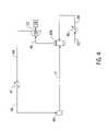
- FIG. 1Ais a schematic diagram of one illustrative embodiment of the present invention employing an economizer heat exchanger and a heat recovery heat exchanger;
- FIGS. 1B and 1Care illustrative temperature-enthalpy plots of a working fluid employed in various systems of the present invention
- FIG. 1Dis a temperature-enthalpy plot of a working fluid employed in an illustrative prior art system
- FIG. 2is a schematic diagram of one illustrative embodiment of the present invention employed in connection with a gas turbine;
- FIG. 3is a schematic diagram of one embodiment of the present invention wherein a desuperheater is employed to cool working fluid exiting a turbine;
- FIG. 4is a schematic diagram of an embodiment of the present invention wherein the present invention may be employed with a low quality heat source such as solar power, geothermal power or an industrial process;
- a low quality heat sourcesuch as solar power, geothermal power or an industrial process
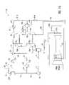
- FIG. 5is a schematic diagram of an illustrative embodiment of the present invention wherein a refrigeration unit and a desuperheater are employed;
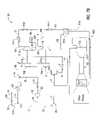
- FIG. 6is a schematic diagram of an embodiment of the present invention involving the use of a refrigeration system, a desuperheater and an economizer/refrigerant condenser;
- FIG. 7Ais a schematic depiction of one illustrative embodiment of the present invention wherein a refrigeration system is employed to chill the inlet air of a gas turbine;
- FIG. 7Bis a schematic depiction of the illustrative system depicted in FIG. 7A with the addition of an intermediate chilled liquid loop;
- FIG. 7Cis a schematic depiction of the system depicted in FIG. 7B with the addition of a plurality of power generators;
- FIG. 8Ais a schematic depiction of one embodiment of the present invention which involves use of a refrigeration system and a combustion gas turbine compressor intercooler as the heat source with intercooling and combustion gas turbine inlet air chilling;
- FIG. 8Bis a schematic depiction of the system depicted in FIG. 8A with the addition of an intermediate chilled liquid loop;
- FIG. 8Cis a schematic depiction of a multi-stage air compressor of a gas turbine wherein air from an intermediate stage of compression is employed to heat the working fluid in the system;
- FIG. 9is a schematic depiction of an embodiment of a system using a refrigeration system and a compressor intercooler as the heat source with intercooling and compressor inlet chilling;
- FIG. 10is a schematic depiction of an embodiment of the present invention using a refrigeration system and a compressor aftercooler as the heat source with intercooling.
- a high pressure liquid 1enters a heat exchanger 17 and exits as a superheated vapor 2 due to heat transfer with a hot fluid, either a gas, a liquid, or a two-phase mixture of gas and liquid entering at 3 and exiting at 4 .
- the vapor 2may be a subcritical or supercritical vapor.
- the heat exchanger 17may be any type of heat exchanger capable of transfer heat from one fluid stream to another fluid stream.
- the heat exchanger 17may be a shell-and-tube heat exchanger, a plate-fin-tube coil type of exchanger, a bare tube or finned tube bundle, a welded plate heat exchanger, etc.
- the source of the hot fluid 3 for the heat exchanger 17may either be a waste heat source (from any of a variety of sources) or heat may intentionally be supplied to the system, e.g., by a gas burner or the like.
- the source of the hot fluid 3 for the heat exchanger 17is a waste heat source such as the exhaust from an internal combustion engine (e.g., a reciprocating diesel engine), a combustion gas turbine, a compressor, or an industrial or manufacturing process.
- a waste heat sourcesuch as the exhaust from an internal combustion engine (e.g., a reciprocating diesel engine), a combustion gas turbine, a compressor, or an industrial or manufacturing process.
- any heat source of sufficient quantity and temperaturemay be utilized if it can be obtained economically.
- the heat exchanger 17may be referred to as a “waste heat recovery heat exchanger,” indicating that the source of the fluid 3 is from what would otherwise be a waste heat source, although the present invention is not limited to such situations.
- the vapor 2is then sent to a suction drum 18 that may contain a demister 18 A therein.
- the suction drum 18may serve several purposes, such as, for example: (a) preventing liquid from entering the turbine 19 ; (b) allowing liquid (or even vapor) to be bypassed around the turbine 19 ; and (c) allowing for startup and shutdown of the system. Any liquid that does collect in the drum 18 will exit through the drain line 8 and be routed through a control valve 21 to reduce it to a pressure equal to the condenser 22 inlet pressure in line 10 .
- Dry vapor 5exits the drum 18 and enters the turbine 19 .
- the vapor 5is expanded in the turbine 19 and the design of the turbine converts kinetic and potential energy of the dry vapor 5 into mechanical energy in the form of torque on an output shaft 27 .
- Any type of commercially available turbine suited for use in the systems described hereinmay be employed, e.g., an expander, a turbo-expander, a power turbine, etc.
- the shaft horsepower available on the shaft 27 of the turbine 19can be used to produce power by driving an illustrative generator 28 , or to drive a compressor, a pump, or other mechanical device, either directly or indirectly.
- a plurality of turbines 19may be employed with the system depicted in FIG. 1A .
- the low pressure, high temperature discharge 6 from the turbineis routed to an economizer heat exchanger 20 that is positioned upstream of the heat exchanger 17 .
- the economizer heat exchanger 20may serve several purposes, such as, for example: (a) the economizer 20 may be used to recover heat from the turbine exhaust 6 and use it to preheat the liquid working fluid 14 prior to the liquid working fluid being introduced into the heat exchanger 17 ; and (b) the economizer 20 may be used to cool the low pressure, high temperature discharge 6 from the turbine 19 and, thus, reduce the required size and cost of the condenser 22 .
- the condenser 22condenses the slightly superheated, low pressure gas 10 and condenses it to the liquid state using water, seawater, air, or other process fluids.
- the condenser 22may be utilized to condense the hot working fluid from a vapor to a liquid at a temperature ranging from approximately 50–200° F.
- the condensed liquid 11is introduced into a drum 23 that may contain a demister 23 A.
- the drum 23may serve several purposes, such as, for example: (a) the design of the drum 23 ensures that the pump 24 has sufficient head to avoid cavitation; (b) the design of the drum 23 ensures that the supply of liquid 12 to the pump 24 is steady; (c) the design of the drum 23 ensures that the pump 24 will not be run dry; (d) the design of the drum 18 provides an opportunity to evacuate any non-condensable vapors from the system through a vent valve 26 via lines 15 , 16 ; (e) the design of the drum 23 allows for the introduction of process liquid into the system; and (f) the design of the drum 23 allows for the introduction of makeup liquid in the event that a small amount of operating fluid is lost.
- the high pressure discharge 13 of the pumpis fed to the economizer heat exchanger 20 through the valve 25 .
- the pump 24may be any type of commercially available pump sufficient to meet the pumping requirements of the systems disclosed herein. In various embodiments, the pump 24 may be sized such that the discharge pressure of the working fluid ranges from approximately 200–800 psia.
- the working fluidenters the heat recovery heat exchanger 17 as a high pressure liquid and leaves as a superheated vapor (stream 2 ).
- the high pressure, superheated vaporis then expanded through a turbine 19 to produce mechanical power.
- the vapor (stream 6 ) exiting the turbine 19is at low pressure and in the superheated state.
- This superheated vaporis then introduced into the economizer heat exchanger 20 to preheat the working fluid going into the heat recovery heat exchanger 17 .
- the economizer heat exchanger 20significantly enhances the efficiency of the system.
- the cooled vapor exiting the economizer heat exchanger 20is condensed at low pressure using the condenser heat exchanger 22 .
- This condenser heat exchanger 22may be water cooled, air cooled, evaporatively cooled, or used as a heat source for district heating, domestic hot water, or similar heating load.
- the condensed low pressure liquid (stream 11 )is fed to the suction of a pump 24 and is pumped to the high pressure required for the heat recovery heat exchanger 17 .
- the present inventionmay employ a single component working fluid that may be comprised of any of, for example, HCFC-123 (R-123), HCFC-134a (R-134a), ammonia (NH 3 ), etc.
- the present inventiondoes not employ water as a working fluid.
- the working fluidmay be comprised of multiple components, none of which are water.
- one or more of the refrigerants identified abovemay be combined or such refrigerants may be combined with a hydrocarbon fluid, e.g., isobutene, etc.
- a hydrocarbon fluide.g., isobutene, etc.
- FIGS. 1B and 1Care illustrative temperature-enthalpy graphs from an illustrative working fluid as it passes through the heat exchanger 17 .
- the slope of the temperature-enthalpy graphmay vary depending upon the application.
- the temperature-enthalpy profilemay not be linear over the entire range of the curve.
- the temperature-enthalpy graphmay be curved as indicated by the dashed line “A” in FIG. 1B .
- FIG. 1Cis another example of an illustrative temperature-enthalpy graph “A” that is slightly curved.
- the temperature-enthalpy profile of the working fluid of the present inventionis fundamentally different from other systems.
- a temperature-enthalpy profile for a typical Rankine cycleis depicted in FIG. 1D .
- the single working fluide.g., water
- Other systemssuch as a Kalina cycle, may exhibit a more non-isothermal conversion of the working fluid from a liquid state to a vapor state, but such systems employ binary component working fluids, such as ammonia and water.
- the non-isothermal process used in practicing aspects of the present inventionis very beneficial in that it provides a greater heat capacity that may be recaptured when the vapor is cooled back to a liquid. That is, due to the higher temperatures involved in such a non-isothermal process, the working fluid, in the super-heated vapor state, contains much more useable heat energy that may be recaptured and used for a variety of purposes. Further, the nearly linear temperature-enthalpy profile allows the exiting temperature of the (waste) heat source to approach more closely to the working fluid temperature 1 entering the heat exchanger 17 .
- the temperature of the working fluidmay be between approximately 50–200° F. at approximately 600 psia at the discharge of the pump 24 .
- the working fluidmay be at a pressure of approximately 30 psia at the discharge of the condenser 22 (see FIG. 1A ) for a system pressure ratio of approximately twenty to one (20:1).
- the temperature of the R-123 working fluid at the exit of the heat exchanger 17may be approximately 200–1000° F.
- the temperature of the R-123 working fluid at the exit of the turbine 19may be approximately 200–800° F. at a pressure of approximately 35 psia.
- the temperature of the R-123 working fluid at the exit of the economizer heat exchanger 20may be approximately 200–700° F. at a pressure of approximately 600 psia at 1 and approximately 60–250° F. at a pressure of 32 psia at 7.
- the temperature of the working fluidmay be between approximately 50–200° F. at approximately 710 psia at the discharge of the pump 24 .
- the working fluidmay be at a pressure of approximately 160 psia at the discharge of the condenser 22 (see FIG. 1A ) for a system pressure ratio of approximately four point four to one (4.4:1).
- the temperature of the R-134a working fluid at the exit of the heat exchanger 17may be approximately 400–800° F.
- the temperature of the R-134a working fluid at the exit of the turbine 19may be approximately 300–700° F. at a pressure of approximately 170 psia.
- the temperature of the R-134a working fluid at the exit of the economizer heat exchanger 20may be approximately 200–400° F. at a pressure of approximately 705 psia at 1 and approximately 60–250° F. at a pressure of 165 psia at 7.
- the temperature of the working fluidmay be approximately 100–120° F. in a solar power application at approximately 1700 psia at the discharge of the pump 24 .
- the working fluidmay be at a pressure of approximately 220 psia at the discharge of the condenser 22 (see FIG. 1A ) for a system pressure ratio of approximately seven point seven to one (7.7:1).
- the temperature of the ammonia working fluid at the exit of the heat exchanger 17may be approximately 600–1000° F.
- the temperature of the ammonia working fluid at the exit of the turbine 19may be approximately 200–650° F. at a pressure of approximately 220 psia.
- the temperature of the ammonia working fluid at the exit of the economizer heat exchanger 20may be approximately 110–250° F. at a pressure of approximately 225 psia.
- the methods and systems described hereinare effective for pressure ratios greater than three to one (3:1) and the pressure ratio is determined by the physical characteristics of the working fluid being utilized.
- the specific selection of the low cycle pressureis determined by the condensing pressure of the working fluid and will be, typically, the saturation pressure of the working fluid at between approximately 60° F. and 160° F., depending on the cooling medium or condenser heat exchanger type and the ambient temperature or ultimate heat sink temperature.
- the specific selection of the high cycle pressureis determined by the thermodynamic properties of the working fluid plus a margin, as a minimum, and by cycle efficiency, pump power consumption, and maximum component design pressures as a maximum.
- FIG. 2a system substantially similar to FIG. 1A is utilized in conjunction with a combustion gas turbine 4 .
- a gas turbine 52is a very suitable device for heat recovery as a significant amount (approximately 65–85%) of the fuel burned to produce power leaves the exhaust section 52 a of the turbine 52 as waste heat.
- any of a variety of commercially available gas turbinesmay be employed with the present invention.
- a schematically depicted stainless steel plate-fin-tube coil 17 Ais utilized as the heat exchanger 17 (shown in FIG.
- the exhaust of the gas turbine 52is typically between approximately 800° F. and 1200° F. and is, therefore, an ideal source of high quality waste heat.
- approximately ten to thirty percent (10–30%) of the available energy in the turbine exhaustis converted into useable power.
- the recovery efficiencycan range from ten (10%) to more than eighty percent (80%) with equivalent gains in overall efficiency.
- FIG. 3Another illustrative embodiment of the present invention is depicted in FIG. 3 .
- the economizer heat exchanger 20FIG. 1A
- the desuperheater 29is essentially a chamber or area, e.g. a pipe or vessel, where the superheated vapor 6 that exits the turbine 19 may be contacted with a sprayed liquid, e.g., R-123, R-134A, or ammonia (i.e., the working fluid).
- the desuperheater 29allows the low pressure, high temperature gas (from stream 6 ) in the combined stream 9 A to be desuperheated to the dew point and introduced to the condenser 22 .
- a heat rejection source 32such as a cooling tower, and a water pump 33 can be utilized for an illustrative water cooled condenser 22 .
- the utilization of an air cooled or evaporative condenseris also possible.
- FIG. 4depicts another illustrative embodiment of the present invention that may be employed to recover heat from a low temperature source, such as a solar energy system where a working fluid, such as ammonia, is boiled isothermally at a low temperature and high pressure. Because of the smaller pressure ratio allowed in such a circuit due to the small difference between the operating temperature of the heat collector 40 and the condensing temperature, the heat collector 40 is operated as a thermosyphon device. The liquid working fluid 41 enters a drum 42 as a high pressure liquid, e.g., approximately 500–900 psia.
- the nearly saturated liquidexits the bottom of the drum 42 as liquid stream 43 under pressure supplied by the liquid level in the drum 42 as is dominated by gravitational force.
- the liquid 43is partially boiled in the heat collector 40 and returns to the drum 42 as a two-phase vapor via stream 44 .
- the warm liquid from the heat collector 40falls to the bottom of the drum 42 and mixes with the incoming liquid working fluid 41 preheating the working fluid 41 to near the saturation temperature, e.g., approximately 150–250° F.
- the warm vapor 45 from the heat collector 40exits the top of the drum 42 and enters the turbine 19 as a high pressure saturated gas at a temperature ranging from approximately 150–250° F.
- the drum 42may contain a demister 42 A.
- the hot vapor 45expands in the turbine 19 to produce power on a shaft 27 and partially condenses during the expansion process.
- the power produced at shaft 27may be utilized to drive a generator 28 or other mechanical device.
- the low pressure two-phase vapor 46 exiting the turbine 19is then condensed and slightly subcooled in the condenser 47 .
- This subcooled liquid 48 exiting the condenser 47is supplied directly to the pump 49 and is pumped to high pressure, e.g., 500–900 psia, as the liquid working fluid 41 .
- the various components depicted in FIG. 4e.g., pumps, compressors, turbines, drums, condensers, etc., may be similar to those described above wherein such equipment is properly sized and configured to operate in the system depicted in FIG. 4 .
- FIG. 5depicts another illustrative embodiment of the present invention wherein a power section substantially similar to FIG. 3 wherein two turbines 19 A, 19 B and a refrigeration system 50 are added to the power recovery system.
- the system depicted in FIG. 5may be designed to only produce refrigeration (i.e., all of the mechanical power drives the compressors R 9 , R 10 ) or to produce a combination of both refrigeration and electrical power.
- Turbine 1 ( 19 A)would be mechanically linked to Compressor 1 (R 9 ) either directly or through an intermediate gearbox.
- Turbine 2 ( 19 B)would be mechanically linked to Compressor 2 (R 10 ). Any of a variety of commercially available compressors may be employed with the present invention.
- the refrigeration loadwould be applied to the refrigerant evaporator R 15 .
- the condenser loadwould be applied to the refrigerant condenser R 11 .
- the cold vapor R 2is supplied to Compressor 1 (R 9 ) where it is compressed to a higher, intermediate pressure.
- the exhaust R 3 from Compressor 1 (R 9 )is sent to a direct contact heat transfer device, e.g., refrigeration drum R 13 , which serves both as a separation device and a heat transfer device.
- This device R 13serves as an intercooler for the intermediate stage of compression and a separator for the second stage of compression.
- the intermediate vapor R 5 from the device R 13is transferred to the inlet of Compressor 2 (R 10 ) and is compressed into to a high pressure gas R 6 .
- This heated, high pressure gasis desuperheated and condensed in the refrigerant condenser R 11 and exits as a saturated or subcooled liquid R 7 .
- This cooled, high pressure liquidis expanded through a high pressure Joule-Thompson expansion valve R 12 into a two-phase gas/liquid mixture R 8 .
- the expansion processcools the mixture.
- the expanded mixture R 8is used as the cooling medium in the direct contact heat transfer device R 13 . Some of the liquid from the expanded mixture R 8 flashes to cool the discharge stream R 3 from Compressor 1 (R 9 ).
- the saturated liquid R 4 from the heat transfer device R 13is expanded through a second, low pressure Joule-Thompson valve R 14 . Again, the expansion cools the stream R 4 and produces a two-phase gas/liquid mixture R 1 . This cold, two-phase mixture R 1 may then be used for a variety of cooling purposes.
- the system depicted in FIG. 5may also be modified by substituting an economizer heat exchanger 20 (see FIG. 1A ) for the desuperheater 29 , valve 31 and spray pump 30 . That is, the refrigeration system 50 depicted in FIG. 5 (compressors, evaporator, condenser) may be incorporated into the system depicted in FIG. 1A . If the illustrative refrigeration system 50 depicted in FIG. 5 were employed, an additional turbine would need to be incorporated into the system depicted in FIG. 1A . In the alternative, any number of turbines paired with any number of compressors might be utilized. The choice of two turbines and two compressors, as depicted in FIG. 5 , is one suggested application of this process.
- the refrigeration system represented by Compressor 1 (R 9 ), Compressor 2 (R 10 ), refrigerant condenser R 11 , refrigerant evaporator R 15 , refrigeration drum R 13 and Joule-Thompson valves R 12 and R 14may be any of a variety of generic, cascade refrigeration systems that are commonly found in industry.
- FIG. 6depicts another illustrative embodiment of the present invention wherein heat rejected by a refrigeration system 50 is recovered and used to preheat the working fluid of the system.
- a power section substantially similar to FIG. 5is provided.
- the refrigerant condenser R 11( FIG. 5 ) is replaced with a refrigerant condenser/economizer 51 and an optional refrigerant subcooler R 16 . That is, in this embodiment, heat from the high temperature refrigerant R 6 exiting the compressor RIO is used as the heat source to preheat the working fluid 1 prior to it entering the heat exchanger 17 .
- the refrigerant condenser/economizer 28is the economizer heat exchanger 20 (depicted in FIG. 1A ) wherein the heating fluid used to preheat the working fluid is taken from the refrigeration system 50 .
- This techniquesubstantially increases the output efficiency of this system.
- FIG. 7Adepicts another illustrative embodiment of the present invention wherein waste heat recovered from a combustion gas turbine 52 is utilized as the heat source for the power system that, in turn, powers a refrigeration system 50 that chills the inlet air to the combustion gas turbine 52 .
- the inlet air to the gas turbine 52is chilled by means of an inlet chilling coil R 17 , i.e., a heat exchanger that evaporates the cold refrigerant R 1 , which is a cold, two phase mixture of liquid and vapor to thereby chill the air entering the combination gas turbine 52 .
- the inlet temperature for the chilling coil R 17may be approximately 32° F.
- the chilling coil R 17 depicted in FIG. 7Amay be, for example, a plate-fin-tube coil type heat exchanger.
- a separation device(not shown) can be utilized between the cold refrigerant R 1 and the chilling coil R 17 to send only liquid to the inlet chilling coil R 17 and to return the vapor, separately to Compressor 1 (R 9 ).
- the heat exchanger 17 Ais placed in the exhaust outlet housing 52 A of the gas turbine 52 , similar to the configuration depicted in FIG. 2 . Exhaust gas from the turbine 52 is used to convert the working fluid flowing through the heat exchanger 17 A from a liquid state to a vapor state.
- FIG. 7Aemploys a desuperheater 29 (similar to that described above in connection with FIG. 3 ).
- the system depicted in FIG. 7Acould also be employed in a system like that shown in FIG. 1A wherein the economizer heat exchanger 20 is employed and the desuperheater 29 , spray pump 30 and valve 31 are eliminated.
- FIG. 7Bdepicts another embodiment of the present invention that is substantially similar to the system depicted in FIG. 7A .
- an intermediate loop R 20 arrangementis utilized to isolate the cold two-phase refrigerant R 1 from the inlet chilling coil R 17 .
- An intermediate liquid loop R 20 and a refrigerant to liquid heat exchanger R 19are utilized to provide chilled liquid to the inlet chilling coil R 17 .
- the cold liquidflows into the chilling coil R 17 via line R 18 and returns via line R 21 .
- the working fluid used in the loop R 20may be water, glycol and water, SoCool, Enviro-KoolTM, a refrigerant, etc.
- the system depicted in FIG. 7Bcould also be employed in a system like that shown in FIG. 1A wherein the economizer heat exchanger 20 is employed and the desuperheater 29 , spray pump 30 and valve 31 are eliminated.
- FIG. 7Cdepicts another illustrative embodiment of the present invention that is substantially similar to FIG. 7B .
- one or more generators 53 , 54may be attached to the shafts 27 A, 27 B that couple Turbine 1 ( 19 A) with Compressor 1 (R 9 ) and Turbine 2 ( 19 B) and Compressor 2 (R 10 ).
- the generators 53 , 54may be connected to the shafts 27 A, 27 B either directly or through an intermediate gearbox.
- the electrical power produced from the generators 53 , 54is transferred through a pair of power leads 55 , 56 to a main power transmission line 57 for delivery to a power grid.
- This illustrative embodimentallows the simultaneous generation of both mechanical power (here used to drive a pair of compressors for refrigeration) and electrical power.
- the system depicted in FIG. 7Ccould also be employed in a system like that shown in FIG. 1A wherein the economizer heat exchanger 20 is employed and the desuperheater 29 , spray pump 30 and valve 31 are eliminated.
- the present inventionmay also be employed in situations when heat is recovered from an intermediate stage of a multi-stage gas compressor used in a combustion gas turbine.
- the energy recoveredwould, most effectively, be utilized to cool the inlet gas, thereby increasing the flow capacity of the compressor or reducing the compressor power requirement while reducing the compressor discharge temperature.
- FIG. 8AOne illustrative embodiment of such a system is depicted in FIG. 8A , which is substantially similar to FIG. 7A .
- the heat sourceis the discharge gas 61 of an intermediate stage of an air compressor (not shown) in the compression section 60 of a combustion gas turbine 52 .
- the heat in this discharged gas 61is recovered by the heat exchanger 17 , and it is used to heat the working fluid of the system.
- FIG. 8Cis a schematic depiction of an illustrative examples of the multiple stages of compression of the air for the gas turbine, wherein the pressures P 1 , P 2 , P 3 and P 4 are successively higher pressures. As the air is compressed, the temperature of the air increases. In the system depicted in FIG.
- the compressed air(heated due to compression) is used as the source of heat for the heat exchanger 17 to heat the working fluid 1 to a vapor 2 that is ultimately provided to the turbines 19 A, 19 B.
- the system depicted in FIG. 8Acould also be employed in a system like that shown in FIG. 1A wherein the economizer heat exchanger 20 is employed and the desuperheater 29 , spray pump 30 and valve 31 are eliminated.
- FIG. 8Bdepicts another illustrative embodiment of the present invention that is substantially similar to FIG. 7B , wherein the heat source is the discharge gas 61 of an intermediate stage of compression of air in a combustion gas turbine 52 recovered by a heat exchanger 17 .
- the cooled gas 62is returned to the next stage of compression.
- This embodimentdiffers from FIG. 8A in that an intermediate heat exchanger R 18 is utilized to isolate the inlet chilling coil R 17 from the balance of the refrigeration system, in a manner similar to that described above with reference to FIG. 7B .
- the system depicted in FIG. 8Bcould also be employed in a system like that shown in FIG. 1A wherein the economizer heat exchanger 20 is employed and the desuperheater 29 , spray pump 30 and valve 31 are eliminated.
- FIG. 9is another illustrative embodiment of a system in accordance with the present invention.
- the system depicted in FIG. 9is substantially similar to the embodiment depicted in FIG. 8B .
- the heat source for heating the working fluid 1is the discharge gas 64 of an intermediate stage of compression of any compressor 63 compressing any gas or combination of gases 65 , the heat of compression of which is recovered by a heat exchanger 17 as the heat input for the process.
- the cooled gas 66is returned to the compressor 63 .
- the refrigeration producedis provided to a refrigerant evaporator heat exchanger R 15 which is utilized to chill the inlet gas 65 to a reduced temperature, as indicated by the stream 66 .
- the gasis compressed to its final pressure, as indicated by stream 67 .
- Such cooling of the incoming gasesmay reduce the required power to operate the compressor 63 , thereby reducing power consumption, increasing pressure rise, increasing throughput, or a combination of these events.
- the system depicted in FIG. 9could also be employed in a system like that shown in FIG. 1A wherein the economizer heat exchanger 20 is employed and the desuperheater 29 , spray pump 30 and valve 31 are eliminated.
- FIG. 10depicts another embodiment of the present invention that is substantially similar to that depicted in FIG. 9 .
- the source of the hot fluid to heat the working fluidis the discharge gas 67 from the final stage of compression of any compressor 63 that may be used to compress any gas or combination of gases 65 .
- the heat of compressionis recovered by a heat exchanger 17 as the heat input for the process.
- the refrigeration producedis provided to a refrigerant evaporator/intercooler heat exchanger R 15 which is utilized to intercool the gas 64 from one or more intermediate stages of the compressor 63 and reduce the required power to operate the compressor 63 , thereby reducing power consumption, increasing pressure rise, increasing throughput, or a combination of these events.
- the cooled gas 66(after it passes through the heat exchanger R 15 ) is returned to the compressor 63 where it is subjected to further compression within one or more stages of the compressor 63 .
- the system depicted in FIG. 10could also be employed in a system like that shown in FIG. 1A wherein the economizer heat exchanger 20 is employed and the desuperheater 29 , spray pump 30 and valve 31 are eliminated.
- the mechanical power available at the output shaft of the turbinemay be utilized directly or through a gearbox to provide mechanical work to drive an electrical power generator to produce electrical power either as a constant voltage and constant frequency AC source or as a DC source which might be rectified to produce AC power at a constant voltage and constant frequency.
- the mechanical power available at the output shaft of the turbinemay be utilized directly or through a gearbox to provide mechanical work to drive any combination of mechanical devices such as a compressor, a pump, a wheel, a propeller, a conveyer, a fan, a gear, or any other mechanical device(s) requiring or accepting mechanical power input.
- the present inventionis not restricted to stationary devices, as it may be utilized in or on an automobile, a ship, an aircraft, a spacecraft, a train, or other non-stationary vessel.
- a specific byproduct of this methodis an effective and dramatic reduction in the emissions of both pollutants and greenhouse gases.
- This methodmay not require any fuel nor does it generate any pollutants or greenhouse gases or any other gases as byproducts.
- Any process to which this method may be applied, such as a gas turbine or a diesel engine,will generate significantly more power with no increase in fuel consumption or pollution.
- the effect of this methodis a net reduction in the specific pollution generation rate on a mass per power produced basis.
- the present inventionis directed to a system comprised of a heat recovery heat exchanger 17 adapted to receive a fluid (liquid or vapor) from a source of waste heat wherein a working fluid 1 is passed through the heat recovery heat exchanger 17 and is converted to vapor via heat transfer from the fluid from waste heat source, a drum 18 adapted to receive the vapor exiting the heat recovery heat exchanger 17 , a turbine 19 adapted to receive the vapor exiting the drum 18 , and an economizer heat exchanger 20 adapted to receive exhaust vapor 6 from the turbine 19 to heat working fluid provided to the heat recovery heat exchanger 17 via heat transfer with the exhaust vapor 6 from the turbine 19 .
- the working fluidmay be comprised of a single component or it may be comprised of multiple components.
- a refrigerant R-123may be employed as the working fluid.
- the vapor that exits the heat recovery heat exchanger 17may be either a super-critical or sub-critical vapor.
- the fluid (liquid or vapor) used to heat the working fluid in the heat recovery heat exchanger 17may be provided from a variety of sources, e.g., waste heat from any industrial process, a solar energy source, a cement plant, a manufacturing process, a reciprocating engine, a gas turbine, etc. Such a system provides increased efficiency relative to prior art systems.
- such a systemmay increase efficiency by approximately 35%. This is due at least in part to the use of the economizer heat exchanger's ( 20 ) use of the exhaust fluid 6 from the turbine 19 to preheat the working fluid prior to its introduction into the heat recovery heat exchanger 17 . Additionally, the present invention may be useful in reducing the amount of waste heat that is absorbed by the environment, as a portion of the exhaust fluid 6 from the turbine 19 is used in preheating the working fluid prior to its introduction into the heat recovery heat exchanger 17 . Due to this reduction in the amount of waste heat, the size of other equipment, such as the condenser 22 depicted in FIG. 1A , may be reduced. Thus, the present invention may be useful in reducing the amount of heat exhausted to the environment, reducing the size of some of the equipment employed in such systems and/or increase the overall operating efficiency of such a system.
- the present inventionis directed to a method that comprises the steps of increasing a temperature of a working fluid in the heat exchanger 20 from a first temperature to a second temperature by transferring heat from an exhaust fluid 6 of a turbine 19 , introducing the working fluid at the second temperature into the heat exchanger 17 wherein the working fluid is converted to a vapor by transferring heat from a fluid from a waste heat source, and introducing the vapor exiting the heat exchanger 17 into a drum 18 and introducing vapor 5 exiting the drum 18 into an inlet of the turbine 19 .
- the present inventionis directed to a method that comprises the steps of increasing the temperature of a working fluid in the heat exchanger 20 from a first temperature to a second temperature by transferring heat from an exhaust fluid 6 of a turbine 19 , introducing the working fluid at the second temperature into the heat exchanger 17 wherein the working fluid is converted to a vapor by transferring heat from a fluid from a waste heat source, and introducing the vapor 5 into an inlet of the turbine 19 .
- the present inventionis generally directed to various systems and methods for producing mechanical power from a heat source.
- the devices employed in practicing the present inventionmay include a heat recovery heat exchanger, a turbine, an economizer heat exchanger, a condenser heat exchanger, and a liquid circulating pump, etc.
- the systemcomprises a first heat exchanger adapted to receive a fluid from a heat source and a working fluid, wherein, when the working fluid is passed through the first heat exchanger, the working fluid is converted to a vapor via heat transfer from the heat contained in the fluid from the heat source, at least one turbine adapted to receive the vapor, and an economizer heat exchanger adapted to receive exhaust vapor from the turbine and the working fluid, wherein a temperature of the working fluid is adapted to be increased via heat transfer with the exhaust vapor from the turbine prior to the introduction of the working fluid into the first heat exchanger.
- the systemfurther comprises a condenser heat exchanger that is adapted to receive the exhaust vapor from the turbine after the exhaust vapor has passed through the economizer heat exchanger and a cooling fluid, wherein a temperature of the exhaust vapor is reduced via heat transfer with the cooling fluid, and a pump that is adapted to circulate the working fluid to the economizer heat exchanger.
- the systemcomprises a first heat exchanger adapted to receive a fluid from a heat source and a working fluid, wherein, when the working fluid is passed through the first heat exchanger, the working fluid is converted to a vapor via heat transfer from the heat contained in the fluid from the heat source, and at least one turbine adapted to receive the vapor.
- the systemfurther comprises a desuperheater heat exchanger adapted to receive exhaust vapor from the turbine and a portion of the working fluid extracted upstream of the first heat exchanger, wherein the temperature of the exhaust vapor from the turbine is adapted to be reduced via heat transfer with the working fluid in the desuperheater heat exchanger, a condenser heat exchanger that is adapted to receive working fluid exiting the desuperheater heat exchanger and a cooling fluid, wherein a temperature of the working fluid is adapted to be reduced via heat transfer with the cooling fluid in the condenser heat exchanger, and a pump adapted to circulate the working fluid to the first heat exchanger.
- a desuperheater heat exchangeradapted to receive exhaust vapor from the turbine and a portion of the working fluid extracted upstream of the first heat exchanger, wherein the temperature of the exhaust vapor from the turbine is adapted to be reduced via heat transfer with the working fluid in the desuperheater heat exchanger, a condenser heat exchanger that is adapted to receive
Landscapes
- Engineering & Computer Science (AREA)
- Chemical & Material Sciences (AREA)
- Combustion & Propulsion (AREA)
- Mechanical Engineering (AREA)
- General Engineering & Computer Science (AREA)
- Engine Equipment That Uses Special Cycles (AREA)
Abstract
Description
Claims (37)
Priority Applications (1)
| Application Number | Priority Date | Filing Date | Title |
|---|---|---|---|
| US10/616,074US6964168B1 (en) | 2003-07-09 | 2003-07-09 | Advanced heat recovery and energy conversion systems for power generation and pollution emissions reduction, and methods of using same |
Applications Claiming Priority (1)
| Application Number | Priority Date | Filing Date | Title |
|---|---|---|---|
| US10/616,074US6964168B1 (en) | 2003-07-09 | 2003-07-09 | Advanced heat recovery and energy conversion systems for power generation and pollution emissions reduction, and methods of using same |
Publications (1)
| Publication Number | Publication Date |
|---|---|
| US6964168B1true US6964168B1 (en) | 2005-11-15 |
Family
ID=35266237
Family Applications (1)
| Application Number | Title | Priority Date | Filing Date |
|---|---|---|---|
| US10/616,074Expired - LifetimeUS6964168B1 (en) | 2003-07-09 | 2003-07-09 | Advanced heat recovery and energy conversion systems for power generation and pollution emissions reduction, and methods of using same |
Country Status (1)
| Country | Link |
|---|---|
| US (1) | US6964168B1 (en) |
Cited By (92)
| Publication number | Priority date | Publication date | Assignee | Title |
|---|---|---|---|---|
| US7047744B1 (en)* | 2004-09-16 | 2006-05-23 | Robertson Stuart J | Dynamic heat sink engine |
| US20070245733A1 (en)* | 2005-10-05 | 2007-10-25 | Tas Ltd. | Power recovery and energy conversion systems and methods of using same |
| WO2008061271A1 (en)* | 2006-11-23 | 2008-05-29 | Mahle König Kommanditgesellschaft Gmbh & Co | Method for converting heat energy and rotary vane piston motor |
| US20080283622A1 (en)* | 2007-05-16 | 2008-11-20 | Dieter Weiss | Method for the transport of heat energy and apparatus for the carrying out of such a method |
| WO2009082372A1 (en)* | 2007-12-21 | 2009-07-02 | Utc Power Corporation | Operating a sub-sea organic rankine cycle (orc) system using individual pressure vessels |
| US20100146930A1 (en)* | 2008-12-11 | 2010-06-17 | General Electric Company | Low Grade Heat Recovery System for Turbine Air Inlet |
| US20100146978A1 (en)* | 2008-12-11 | 2010-06-17 | General Electric Company | Gas Turbine Base Load Control by Chilling Modulation |
| US20100146977A1 (en)* | 2008-12-11 | 2010-06-17 | General Electric Company | Deep Chilled Air Washer |
| US20100146976A1 (en)* | 2008-12-11 | 2010-06-17 | General Electric Company | Inlet Air Heating and Cooling System |
| US20100146981A1 (en)* | 2008-12-11 | 2010-06-17 | General Electric Company | Turbine Inlet Air Heat Pump-Type System |
| US20100263607A1 (en)* | 2009-04-16 | 2010-10-21 | Andrew Travaly | Desuperheater for a steam turbine generator |
| US20100319348A1 (en)* | 2009-05-26 | 2010-12-23 | Worleyparsons Group, Inc. | Waste heat recovery system |
| US20110016863A1 (en)* | 2009-07-23 | 2011-01-27 | Cummins Intellectual Properties, Inc. | Energy recovery system using an organic rankine cycle |
| US20110048012A1 (en)* | 2009-09-02 | 2011-03-03 | Cummins Intellectual Properties, Inc. | Energy recovery system and method using an organic rankine cycle with condenser pressure regulation |
| US20110072816A1 (en)* | 2008-05-12 | 2011-03-31 | Cummins Intellectual Properties, Inc. | Waste heat recovery system with constant power output |
| US20110083620A1 (en)* | 2009-10-08 | 2011-04-14 | Yoon Yong K | Waste Heat Recovery System and Method Thereof |
| US7958739B1 (en)* | 2008-08-04 | 2011-06-14 | Leabo Lawrence D | Refrigeration hot gas desuperheater systems |
| US20110173981A1 (en)* | 2010-01-15 | 2011-07-21 | Alstom Technology Ltd. | Utilization of low grade heat in a refrigeration cycle |
| US20110185729A1 (en)* | 2009-09-17 | 2011-08-04 | Held Timothy J | Thermal energy conversion device |
| US8087248B2 (en)* | 2008-10-06 | 2012-01-03 | Kalex, Llc | Method and apparatus for the utilization of waste heat from gaseous heat sources carrying substantial quantities of dust |
| US20120006024A1 (en)* | 2010-07-09 | 2012-01-12 | Energent Corporation | Multi-component two-phase power cycle |
| US20120042656A1 (en)* | 2010-08-20 | 2012-02-23 | Icr Turbine Engine Corporation | Gas turbine engine with exhaust rankine cycle |
| US20120111025A1 (en)* | 2010-10-22 | 2012-05-10 | Man Diesel & Turbo Se | System For The Generation Of Mechanical And/Or Electrical Energy |
| WO2013030476A1 (en) | 2011-08-30 | 2013-03-07 | Arkema France | Tetrafluoropropene-based supercritical heat-transfer fluids |
| US20130160450A1 (en)* | 2011-12-22 | 2013-06-27 | Frederick J. Cogswell | Hemetic motor cooling for high temperature organic rankine cycle system |
| US20130174602A1 (en)* | 2011-11-23 | 2013-07-11 | Tenoroc Llc | Aerodynamic separation nozzle |
| US8499874B2 (en) | 2009-05-12 | 2013-08-06 | Icr Turbine Engine Corporation | Gas turbine energy storage and conversion system |
| US20130227940A1 (en)* | 2010-11-16 | 2013-09-05 | Technion Research And Development Foundation Ltd. | Energy conversion from fluid flow |
| US8613195B2 (en) | 2009-09-17 | 2013-12-24 | Echogen Power Systems, Llc | Heat engine and heat to electricity systems and methods with working fluid mass management control |
| US8616001B2 (en) | 2010-11-29 | 2013-12-31 | Echogen Power Systems, Llc | Driven starter pump and start sequence |
| US8616323B1 (en) | 2009-03-11 | 2013-12-31 | Echogen Power Systems | Hybrid power systems |
| US20140007577A1 (en)* | 2010-10-14 | 2014-01-09 | Trond Melhus | Method and System for the Utilization of an Energy Source of Relatively Low Temperature |
| US8652996B2 (en) | 2011-12-31 | 2014-02-18 | Sanford, L.P. | Irreversible thermochromic pigment capsules |
| US8664156B2 (en) | 2011-12-31 | 2014-03-04 | Sanford, L.P. | Irreversible thermochromic ink compositions |
| US8669670B2 (en) | 2010-09-03 | 2014-03-11 | Icr Turbine Engine Corporation | Gas turbine engine configurations |
| US8683801B2 (en) | 2010-08-13 | 2014-04-01 | Cummins Intellectual Properties, Inc. | Rankine cycle condenser pressure control using an energy conversion device bypass valve |
| US8709973B2 (en) | 2011-12-31 | 2014-04-29 | Sanford, L.P. | Irreversible thermochromic ink compositions |
| US8707914B2 (en) | 2011-02-28 | 2014-04-29 | Cummins Intellectual Property, Inc. | Engine having integrated waste heat recovery |
| US8752378B2 (en) | 2010-08-09 | 2014-06-17 | Cummins Intellectual Properties, Inc. | Waste heat recovery system for recapturing energy after engine aftertreatment systems |
| US8776517B2 (en) | 2008-03-31 | 2014-07-15 | Cummins Intellectual Properties, Inc. | Emissions-critical charge cooling using an organic rankine cycle |
| US8783034B2 (en) | 2011-11-07 | 2014-07-22 | Echogen Power Systems, Llc | Hot day cycle |
| US8800285B2 (en) | 2011-01-06 | 2014-08-12 | Cummins Intellectual Property, Inc. | Rankine cycle waste heat recovery system |
| US8813497B2 (en) | 2009-09-17 | 2014-08-26 | Echogen Power Systems, Llc | Automated mass management control |
| US8826662B2 (en) | 2010-12-23 | 2014-09-09 | Cummins Intellectual Property, Inc. | Rankine cycle system and method |
| US8857186B2 (en) | 2010-11-29 | 2014-10-14 | Echogen Power Systems, L.L.C. | Heat engine cycles for high ambient conditions |
| US8865621B2 (en) | 2012-08-06 | 2014-10-21 | Sanford, L.P. | Irreversible color changing ink compositions |
| US8866334B2 (en) | 2010-03-02 | 2014-10-21 | Icr Turbine Engine Corporation | Dispatchable power from a renewable energy facility |
| US8869531B2 (en) | 2009-09-17 | 2014-10-28 | Echogen Power Systems, Llc | Heat engines with cascade cycles |
| US8893495B2 (en) | 2012-07-16 | 2014-11-25 | Cummins Intellectual Property, Inc. | Reversible waste heat recovery system and method |
| US8919328B2 (en) | 2011-01-20 | 2014-12-30 | Cummins Intellectual Property, Inc. | Rankine cycle waste heat recovery system and method with improved EGR temperature control |
| US20150000260A1 (en)* | 2013-06-26 | 2015-01-01 | Walter F. Burrows | Environmentally friendly power generation process |
| US8984895B2 (en) | 2010-07-09 | 2015-03-24 | Icr Turbine Engine Corporation | Metallic ceramic spool for a gas turbine engine |
| US9014791B2 (en) | 2009-04-17 | 2015-04-21 | Echogen Power Systems, Llc | System and method for managing thermal issues in gas turbine engines |
| US9021808B2 (en) | 2011-01-10 | 2015-05-05 | Cummins Intellectual Property, Inc. | Rankine cycle waste heat recovery system |
| US9051873B2 (en) | 2011-05-20 | 2015-06-09 | Icr Turbine Engine Corporation | Ceramic-to-metal turbine shaft attachment |
| US9062898B2 (en) | 2011-10-03 | 2015-06-23 | Echogen Power Systems, Llc | Carbon dioxide refrigeration cycle |
| US9091278B2 (en) | 2012-08-20 | 2015-07-28 | Echogen Power Systems, Llc | Supercritical working fluid circuit with a turbo pump and a start pump in series configuration |
| US9118226B2 (en) | 2012-10-12 | 2015-08-25 | Echogen Power Systems, Llc | Heat engine system with a supercritical working fluid and processes thereof |
| US9140209B2 (en) | 2012-11-16 | 2015-09-22 | Cummins Inc. | Rankine cycle waste heat recovery system |
| US9217338B2 (en) | 2010-12-23 | 2015-12-22 | Cummins Intellectual Property, Inc. | System and method for regulating EGR cooling using a rankine cycle |
| US9316404B2 (en) | 2009-08-04 | 2016-04-19 | Echogen Power Systems, Llc | Heat pump with integral solar collector |
| US9341084B2 (en) | 2012-10-12 | 2016-05-17 | Echogen Power Systems, Llc | Supercritical carbon dioxide power cycle for waste heat recovery |
| US20160169071A1 (en)* | 2014-12-11 | 2016-06-16 | Sridhar Deivasigamani | Combined heat and power system |
| US9376937B2 (en) | 2010-02-22 | 2016-06-28 | University Of South Florida | Method and system for generating power from low- and mid- temperature heat sources using supercritical rankine cycles with zeotropic mixtures |
| US9385574B1 (en)* | 2013-06-26 | 2016-07-05 | Ever Source Science & Technology Development Co., Ltd. | Heat transfer fluid based zero-gas-emission power generation |
| US9441504B2 (en) | 2009-06-22 | 2016-09-13 | Echogen Power Systems, Llc | System and method for managing thermal issues in one or more industrial processes |
| US9470115B2 (en) | 2010-08-11 | 2016-10-18 | Cummins Intellectual Property, Inc. | Split radiator design for heat rejection optimization for a waste heat recovery system |
| US9638065B2 (en) | 2013-01-28 | 2017-05-02 | Echogen Power Systems, Llc | Methods for reducing wear on components of a heat engine system at startup |
| US20170131027A1 (en)* | 2015-11-06 | 2017-05-11 | Fluor Technologies Corporation | Systems and Methods for LNG Refrigeration and Liquefaction |
| US9719423B2 (en) | 2012-09-04 | 2017-08-01 | General Electric Company | Inlet air chilling system with humidity control and energy recovery |
| US9752460B2 (en) | 2013-01-28 | 2017-09-05 | Echogen Power Systems, Llc | Process for controlling a power turbine throttle valve during a supercritical carbon dioxide rankine cycle |
| US9816739B2 (en) | 2011-09-02 | 2017-11-14 | Carrier Corporation | Refrigeration system and refrigeration method providing heat recovery |
| US9845711B2 (en) | 2013-05-24 | 2017-12-19 | Cummins Inc. | Waste heat recovery system |
| US20180023423A1 (en)* | 2011-04-18 | 2018-01-25 | Holtec International | Autonomous self-powered system for removing thermal energy from pools of liquid heated by radioactive materials, and method of the same |
| US10094288B2 (en) | 2012-07-24 | 2018-10-09 | Icr Turbine Engine Corporation | Ceramic-to-metal turbine volute attachment for a gas turbine engine |
| US20200056511A1 (en)* | 2017-01-03 | 2020-02-20 | William M. Conlon | Cryogenic combined cycle power plant |
| US10934895B2 (en) | 2013-03-04 | 2021-03-02 | Echogen Power Systems, Llc | Heat engine systems with high net power supercritical carbon dioxide circuits |
| US11168925B1 (en) | 2018-11-01 | 2021-11-09 | Booz Allen Hamilton Inc. | Thermal management systems |
| US11187112B2 (en) | 2018-06-27 | 2021-11-30 | Echogen Power Systems Llc | Systems and methods for generating electricity via a pumped thermal energy storage system |
| US11293309B2 (en) | 2014-11-03 | 2022-04-05 | Echogen Power Systems, Llc | Active thrust management of a turbopump within a supercritical working fluid circuit in a heat engine system |
| US11293673B1 (en) | 2018-11-01 | 2022-04-05 | Booz Allen Hamilton Inc. | Thermal management systems |
| US11313594B1 (en) | 2018-11-01 | 2022-04-26 | Booz Allen Hamilton Inc. | Thermal management systems for extended operation |
| US11435120B2 (en) | 2020-05-05 | 2022-09-06 | Echogen Power Systems (Delaware), Inc. | Split expansion heat pump cycle |
| US11561030B1 (en) | 2020-06-15 | 2023-01-24 | Booz Allen Hamilton Inc. | Thermal management systems |
| US11569001B2 (en) | 2008-04-29 | 2023-01-31 | Holtec International | Autonomous self-powered system for removing thermal energy from pools of liquid heated by radioactive materials |
| US11629638B2 (en) | 2020-12-09 | 2023-04-18 | Supercritical Storage Company, Inc. | Three reservoir electric thermal energy storage system |
| US11644221B1 (en) | 2019-03-05 | 2023-05-09 | Booz Allen Hamilton Inc. | Open cycle thermal management system with a vapor pump device |
| US11752837B1 (en) | 2019-11-15 | 2023-09-12 | Booz Allen Hamilton Inc. | Processing vapor exhausted by thermal management systems |
| US11796230B1 (en) | 2019-06-18 | 2023-10-24 | Booz Allen Hamilton Inc. | Thermal management systems |
| US11835270B1 (en) | 2018-06-22 | 2023-12-05 | Booz Allen Hamilton Inc. | Thermal management systems |
| US20240310034A1 (en)* | 2022-07-17 | 2024-09-19 | Ge-Hitachi Nuclear Energy Americas Llc | Heat pump integrated with a nuclear power plant |
| US12331664B2 (en) | 2023-02-07 | 2025-06-17 | Supercritical Storage Company, Inc. | Waste heat integration into pumped thermal energy storage |
Citations (26)
| Publication number | Priority date | Publication date | Assignee | Title |
|---|---|---|---|---|
| US1632575A (en)* | 1925-07-07 | 1927-06-14 | Siemens Schuckertwerke Gmbh | Arrangement or system for the generation of steam |
| JPS53132638A (en)* | 1977-04-25 | 1978-11-18 | Mitsubishi Heavy Ind Ltd | Power recovery system |
| JPS5968505A (en)* | 1982-10-14 | 1984-04-18 | Toshiba Corp | Low boiling point media cycle plant |
| US4557112A (en)* | 1981-12-18 | 1985-12-10 | Solmecs Corporation | Method and apparatus for converting thermal energy |
| US4586340A (en) | 1985-01-22 | 1986-05-06 | Kalina Alexander Ifaevich | Method and apparatus for implementing a thermodynamic cycle using a fluid of changing concentration |
| US4604867A (en) | 1985-02-26 | 1986-08-12 | Kalina Alexander Ifaevich | Method and apparatus for implementing a thermodynamic cycle with intercooling |
| US4732005A (en) | 1987-02-17 | 1988-03-22 | Kalina Alexander Ifaevich | Direct fired power cycle |
| US4899545A (en) | 1989-01-11 | 1990-02-13 | Kalina Alexander Ifaevich | Method and apparatus for thermodynamic cycle |
| US5029444A (en) | 1990-08-15 | 1991-07-09 | Kalina Alexander Ifaevich | Method and apparatus for converting low temperature heat to electric power |
| US5095708A (en) | 1991-03-28 | 1992-03-17 | Kalina Alexander Ifaevich | Method and apparatus for converting thermal energy into electric power |
| US5440882A (en) | 1993-11-03 | 1995-08-15 | Exergy, Inc. | Method and apparatus for converting heat from geothermal liquid and geothermal steam to electric power |
| US5557936A (en) | 1995-07-27 | 1996-09-24 | Praxair Technology, Inc. | Thermodynamic power generation system employing a three component working fluid |
| US5572871A (en) | 1994-07-29 | 1996-11-12 | Exergy, Inc. | System and apparatus for conversion of thermal energy into mechanical and electrical power |
| US5754613A (en)* | 1996-02-07 | 1998-05-19 | Kabushiki Kaisha Toshiba | Power plant |
| US5953918A (en)* | 1998-02-05 | 1999-09-21 | Exergy, Inc. | Method and apparatus of converting heat to useful energy |
| US6058695A (en) | 1998-04-20 | 2000-05-09 | General Electric Co. | Gas turbine inlet air cooling method for combined cycle power plants |
| US6195997B1 (en) | 1999-04-15 | 2001-03-06 | Lewis Monroe Power Inc. | Energy conversion system |
| US6269644B1 (en) | 2000-06-06 | 2001-08-07 | Donald C. Erickson | Absorption power cycle with two pumped absorbers |
| US6318065B1 (en) | 1999-08-06 | 2001-11-20 | Tom L. Pierson | System for chilling inlet air for gas turbines |
| US6321552B1 (en) | 1998-06-22 | 2001-11-27 | Silentor Holding A/S | Waste heat recovery system |
| US6347520B1 (en) | 2001-02-06 | 2002-02-19 | General Electric Company | Method for Kalina combined cycle power plant with district heating capability |
| US20020162330A1 (en)* | 2001-03-01 | 2002-11-07 | Youji Shimizu | Power generating system |
| US6571548B1 (en) | 1998-12-31 | 2003-06-03 | Ormat Industries Ltd. | Waste heat recovery in an organic energy converter using an intermediate liquid cycle |
| US6581384B1 (en)* | 2001-12-10 | 2003-06-24 | Dwayne M. Benson | Cooling and heating apparatus and process utilizing waste heat and method of control |
| US6615585B2 (en) | 1998-03-24 | 2003-09-09 | Mitsubishi Heavy Industries, Ltd. | Intake-air cooling type gas turbine power equipment and combined power plant using same |
| US6857268B2 (en)* | 2002-07-22 | 2005-02-22 | Wow Energy, Inc. | Cascading closed loop cycle (CCLC) |
- 2003
- 2003-07-09USUS10/616,074patent/US6964168B1/ennot_activeExpired - Lifetime
Patent Citations (28)
| Publication number | Priority date | Publication date | Assignee | Title |
|---|---|---|---|---|
| US1632575A (en)* | 1925-07-07 | 1927-06-14 | Siemens Schuckertwerke Gmbh | Arrangement or system for the generation of steam |
| JPS53132638A (en)* | 1977-04-25 | 1978-11-18 | Mitsubishi Heavy Ind Ltd | Power recovery system |
| US4557112A (en)* | 1981-12-18 | 1985-12-10 | Solmecs Corporation | Method and apparatus for converting thermal energy |
| JPS5968505A (en)* | 1982-10-14 | 1984-04-18 | Toshiba Corp | Low boiling point media cycle plant |
| US4586340A (en) | 1985-01-22 | 1986-05-06 | Kalina Alexander Ifaevich | Method and apparatus for implementing a thermodynamic cycle using a fluid of changing concentration |
| US4604867A (en) | 1985-02-26 | 1986-08-12 | Kalina Alexander Ifaevich | Method and apparatus for implementing a thermodynamic cycle with intercooling |
| US4732005A (en) | 1987-02-17 | 1988-03-22 | Kalina Alexander Ifaevich | Direct fired power cycle |
| US4899545A (en) | 1989-01-11 | 1990-02-13 | Kalina Alexander Ifaevich | Method and apparatus for thermodynamic cycle |
| US5029444A (en) | 1990-08-15 | 1991-07-09 | Kalina Alexander Ifaevich | Method and apparatus for converting low temperature heat to electric power |
| US5095708A (en) | 1991-03-28 | 1992-03-17 | Kalina Alexander Ifaevich | Method and apparatus for converting thermal energy into electric power |
| US5440882A (en) | 1993-11-03 | 1995-08-15 | Exergy, Inc. | Method and apparatus for converting heat from geothermal liquid and geothermal steam to electric power |
| US5572871A (en) | 1994-07-29 | 1996-11-12 | Exergy, Inc. | System and apparatus for conversion of thermal energy into mechanical and electrical power |
| US5557936A (en) | 1995-07-27 | 1996-09-24 | Praxair Technology, Inc. | Thermodynamic power generation system employing a three component working fluid |
| US5754613A (en)* | 1996-02-07 | 1998-05-19 | Kabushiki Kaisha Toshiba | Power plant |
| US5953918A (en)* | 1998-02-05 | 1999-09-21 | Exergy, Inc. | Method and apparatus of converting heat to useful energy |
| US6615585B2 (en) | 1998-03-24 | 2003-09-09 | Mitsubishi Heavy Industries, Ltd. | Intake-air cooling type gas turbine power equipment and combined power plant using same |
| US6058695A (en) | 1998-04-20 | 2000-05-09 | General Electric Co. | Gas turbine inlet air cooling method for combined cycle power plants |
| US6321552B1 (en) | 1998-06-22 | 2001-11-27 | Silentor Holding A/S | Waste heat recovery system |
| US6571548B1 (en) | 1998-12-31 | 2003-06-03 | Ormat Industries Ltd. | Waste heat recovery in an organic energy converter using an intermediate liquid cycle |
| US6195997B1 (en) | 1999-04-15 | 2001-03-06 | Lewis Monroe Power Inc. | Energy conversion system |
| US6318065B1 (en) | 1999-08-06 | 2001-11-20 | Tom L. Pierson | System for chilling inlet air for gas turbines |
| US6470686B2 (en) | 1999-08-06 | 2002-10-29 | Tom L. Pierson | System for chilling inlet air for gas turbines |
| US20020017095A1 (en) | 1999-08-06 | 2002-02-14 | Pierson Tom L. | System for chilling inlet air for gas turbines |
| US6269644B1 (en) | 2000-06-06 | 2001-08-07 | Donald C. Erickson | Absorption power cycle with two pumped absorbers |
| US6347520B1 (en) | 2001-02-06 | 2002-02-19 | General Electric Company | Method for Kalina combined cycle power plant with district heating capability |
| US20020162330A1 (en)* | 2001-03-01 | 2002-11-07 | Youji Shimizu | Power generating system |
| US6581384B1 (en)* | 2001-12-10 | 2003-06-24 | Dwayne M. Benson | Cooling and heating apparatus and process utilizing waste heat and method of control |
| US6857268B2 (en)* | 2002-07-22 | 2005-02-22 | Wow Energy, Inc. | Cascading closed loop cycle (CCLC) |
Cited By (141)
| Publication number | Priority date | Publication date | Assignee | Title |
|---|---|---|---|---|
| US7047744B1 (en)* | 2004-09-16 | 2006-05-23 | Robertson Stuart J | Dynamic heat sink engine |
| US20060123789A1 (en)* | 2004-09-16 | 2006-06-15 | Robertson Stuart J | Dynamic heat sink engine |
| US20070245733A1 (en)* | 2005-10-05 | 2007-10-25 | Tas Ltd. | Power recovery and energy conversion systems and methods of using same |
| US7287381B1 (en)* | 2005-10-05 | 2007-10-30 | Modular Energy Solutions, Ltd. | Power recovery and energy conversion systems and methods of using same |
| WO2008069771A3 (en)* | 2005-10-05 | 2009-04-09 | Modular Energy Solutions Ltd | Power recovery and energy conversion systems and methods of using same |
| WO2008061271A1 (en)* | 2006-11-23 | 2008-05-29 | Mahle König Kommanditgesellschaft Gmbh & Co | Method for converting heat energy and rotary vane piston motor |
| US20080283622A1 (en)* | 2007-05-16 | 2008-11-20 | Dieter Weiss | Method for the transport of heat energy and apparatus for the carrying out of such a method |
| US8375716B2 (en)* | 2007-12-21 | 2013-02-19 | United Technologies Corporation | Operating a sub-sea organic Rankine cycle (ORC) system using individual pressure vessels |
| WO2009082372A1 (en)* | 2007-12-21 | 2009-07-02 | Utc Power Corporation | Operating a sub-sea organic rankine cycle (orc) system using individual pressure vessels |
| US20110138809A1 (en)* | 2007-12-21 | 2011-06-16 | United Technologies Corporation | Operating a sub-sea organic rankine cycle (orc) system using individual pressure vessels |
| US8776517B2 (en) | 2008-03-31 | 2014-07-15 | Cummins Intellectual Properties, Inc. | Emissions-critical charge cooling using an organic rankine cycle |
| US11569001B2 (en) | 2008-04-29 | 2023-01-31 | Holtec International | Autonomous self-powered system for removing thermal energy from pools of liquid heated by radioactive materials |
| US12243662B2 (en) | 2008-04-29 | 2025-03-04 | Holtec International | Neutron absorbing apparatus |
| US8635871B2 (en) | 2008-05-12 | 2014-01-28 | Cummins Inc. | Waste heat recovery system with constant power output |
| US8407998B2 (en) | 2008-05-12 | 2013-04-02 | Cummins Inc. | Waste heat recovery system with constant power output |
| US20110072816A1 (en)* | 2008-05-12 | 2011-03-31 | Cummins Intellectual Properties, Inc. | Waste heat recovery system with constant power output |
| US7958739B1 (en)* | 2008-08-04 | 2011-06-14 | Leabo Lawrence D | Refrigeration hot gas desuperheater systems |
| US8087248B2 (en)* | 2008-10-06 | 2012-01-03 | Kalex, Llc | Method and apparatus for the utilization of waste heat from gaseous heat sources carrying substantial quantities of dust |
| US20100146977A1 (en)* | 2008-12-11 | 2010-06-17 | General Electric Company | Deep Chilled Air Washer |
| US8201411B2 (en) | 2008-12-11 | 2012-06-19 | General Electric Company | Deep chilled air washer |
| US20100146930A1 (en)* | 2008-12-11 | 2010-06-17 | General Electric Company | Low Grade Heat Recovery System for Turbine Air Inlet |
| US20100146978A1 (en)* | 2008-12-11 | 2010-06-17 | General Electric Company | Gas Turbine Base Load Control by Chilling Modulation |
| US9470149B2 (en) | 2008-12-11 | 2016-10-18 | General Electric Company | Turbine inlet air heat pump-type system |
| US8468830B2 (en) | 2008-12-11 | 2013-06-25 | General Electric Company | Inlet air heating and cooling system |
| US20100146976A1 (en)* | 2008-12-11 | 2010-06-17 | General Electric Company | Inlet Air Heating and Cooling System |
| US20100146981A1 (en)* | 2008-12-11 | 2010-06-17 | General Electric Company | Turbine Inlet Air Heat Pump-Type System |
| US8356466B2 (en) | 2008-12-11 | 2013-01-22 | General Electric Company | Low grade heat recovery system for turbine air inlet |
| US8616323B1 (en) | 2009-03-11 | 2013-12-31 | Echogen Power Systems | Hybrid power systems |
| RU2529971C2 (en)* | 2009-04-16 | 2014-10-10 | Дженерал Электрик Компани | Turbine superheated steam generating unit |
| US8347827B2 (en) | 2009-04-16 | 2013-01-08 | General Electric Company | Desuperheater for a steam turbine generator |
| US20100263607A1 (en)* | 2009-04-16 | 2010-10-21 | Andrew Travaly | Desuperheater for a steam turbine generator |
| US9014791B2 (en) | 2009-04-17 | 2015-04-21 | Echogen Power Systems, Llc | System and method for managing thermal issues in gas turbine engines |
| US8708083B2 (en) | 2009-05-12 | 2014-04-29 | Icr Turbine Engine Corporation | Gas turbine energy storage and conversion system |
| US8499874B2 (en) | 2009-05-12 | 2013-08-06 | Icr Turbine Engine Corporation | Gas turbine energy storage and conversion system |
| US20100319348A1 (en)* | 2009-05-26 | 2010-12-23 | Worleyparsons Group, Inc. | Waste heat recovery system |
| US9441504B2 (en) | 2009-06-22 | 2016-09-13 | Echogen Power Systems, Llc | System and method for managing thermal issues in one or more industrial processes |
| US20110016863A1 (en)* | 2009-07-23 | 2011-01-27 | Cummins Intellectual Properties, Inc. | Energy recovery system using an organic rankine cycle |
| US8544274B2 (en) | 2009-07-23 | 2013-10-01 | Cummins Intellectual Properties, Inc. | Energy recovery system using an organic rankine cycle |
| US9316404B2 (en) | 2009-08-04 | 2016-04-19 | Echogen Power Systems, Llc | Heat pump with integral solar collector |
| US20110048012A1 (en)* | 2009-09-02 | 2011-03-03 | Cummins Intellectual Properties, Inc. | Energy recovery system and method using an organic rankine cycle with condenser pressure regulation |
| US8627663B2 (en) | 2009-09-02 | 2014-01-14 | Cummins Intellectual Properties, Inc. | Energy recovery system and method using an organic rankine cycle with condenser pressure regulation |
| US8613195B2 (en) | 2009-09-17 | 2013-12-24 | Echogen Power Systems, Llc | Heat engine and heat to electricity systems and methods with working fluid mass management control |
| US8794002B2 (en) | 2009-09-17 | 2014-08-05 | Echogen Power Systems | Thermal energy conversion method |
| US9115605B2 (en)* | 2009-09-17 | 2015-08-25 | Echogen Power Systems, Llc | Thermal energy conversion device |
| US9458738B2 (en) | 2009-09-17 | 2016-10-04 | Echogen Power Systems, Llc | Heat engine and heat to electricity systems and methods with working fluid mass management control |
| US9863282B2 (en) | 2009-09-17 | 2018-01-09 | Echogen Power System, LLC | Automated mass management control |
| US8966901B2 (en) | 2009-09-17 | 2015-03-03 | Dresser-Rand Company | Heat engine and heat to electricity systems and methods for working fluid fill system |
| US20110185729A1 (en)* | 2009-09-17 | 2011-08-04 | Held Timothy J | Thermal energy conversion device |
| US8869531B2 (en) | 2009-09-17 | 2014-10-28 | Echogen Power Systems, Llc | Heat engines with cascade cycles |
| US8813497B2 (en) | 2009-09-17 | 2014-08-26 | Echogen Power Systems, Llc | Automated mass management control |
| US20110083620A1 (en)* | 2009-10-08 | 2011-04-14 | Yoon Yong K | Waste Heat Recovery System and Method Thereof |
| US20110173981A1 (en)* | 2010-01-15 | 2011-07-21 | Alstom Technology Ltd. | Utilization of low grade heat in a refrigeration cycle |
| US9376937B2 (en) | 2010-02-22 | 2016-06-28 | University Of South Florida | Method and system for generating power from low- and mid- temperature heat sources using supercritical rankine cycles with zeotropic mixtures |
| US8866334B2 (en) | 2010-03-02 | 2014-10-21 | Icr Turbine Engine Corporation | Dispatchable power from a renewable energy facility |
| US20120006024A1 (en)* | 2010-07-09 | 2012-01-12 | Energent Corporation | Multi-component two-phase power cycle |
| US8984895B2 (en) | 2010-07-09 | 2015-03-24 | Icr Turbine Engine Corporation | Metallic ceramic spool for a gas turbine engine |
| US8752378B2 (en) | 2010-08-09 | 2014-06-17 | Cummins Intellectual Properties, Inc. | Waste heat recovery system for recapturing energy after engine aftertreatment systems |
| US9470115B2 (en) | 2010-08-11 | 2016-10-18 | Cummins Intellectual Property, Inc. | Split radiator design for heat rejection optimization for a waste heat recovery system |
| US8683801B2 (en) | 2010-08-13 | 2014-04-01 | Cummins Intellectual Properties, Inc. | Rankine cycle condenser pressure control using an energy conversion device bypass valve |
| US20120042656A1 (en)* | 2010-08-20 | 2012-02-23 | Icr Turbine Engine Corporation | Gas turbine engine with exhaust rankine cycle |
| WO2012024683A1 (en)* | 2010-08-20 | 2012-02-23 | Icr Turbine Engine Corporation | Gas turbine engine with exhaust rankine cycle |
| US8669670B2 (en) | 2010-09-03 | 2014-03-11 | Icr Turbine Engine Corporation | Gas turbine engine configurations |
| US20140007577A1 (en)* | 2010-10-14 | 2014-01-09 | Trond Melhus | Method and System for the Utilization of an Energy Source of Relatively Low Temperature |
| US20120111025A1 (en)* | 2010-10-22 | 2012-05-10 | Man Diesel & Turbo Se | System For The Generation Of Mechanical And/Or Electrical Energy |
| US8881528B2 (en)* | 2010-10-22 | 2014-11-11 | Man Diesel & Turbo Se | System for the generation of mechanical and/or electrical energy |
| US20130227940A1 (en)* | 2010-11-16 | 2013-09-05 | Technion Research And Development Foundation Ltd. | Energy conversion from fluid flow |
| US9841000B2 (en)* | 2010-11-16 | 2017-12-12 | Technion Research And Development Foundation Ltd. | Energy conversion from fluid flow |
| US8857186B2 (en) | 2010-11-29 | 2014-10-14 | Echogen Power Systems, L.L.C. | Heat engine cycles for high ambient conditions |
| US8616001B2 (en) | 2010-11-29 | 2013-12-31 | Echogen Power Systems, Llc | Driven starter pump and start sequence |
| US9410449B2 (en) | 2010-11-29 | 2016-08-09 | Echogen Power Systems, Llc | Driven starter pump and start sequence |
| US9702272B2 (en) | 2010-12-23 | 2017-07-11 | Cummins Intellectual Property, Inc. | Rankine cycle system and method |
| US9745869B2 (en) | 2010-12-23 | 2017-08-29 | Cummins Intellectual Property, Inc. | System and method for regulating EGR cooling using a Rankine cycle |
| US8826662B2 (en) | 2010-12-23 | 2014-09-09 | Cummins Intellectual Property, Inc. | Rankine cycle system and method |
| US9217338B2 (en) | 2010-12-23 | 2015-12-22 | Cummins Intellectual Property, Inc. | System and method for regulating EGR cooling using a rankine cycle |
| US8800285B2 (en) | 2011-01-06 | 2014-08-12 | Cummins Intellectual Property, Inc. | Rankine cycle waste heat recovery system |
| US9334760B2 (en) | 2011-01-06 | 2016-05-10 | Cummins Intellectual Property, Inc. | Rankine cycle waste heat recovery system |
| US9021808B2 (en) | 2011-01-10 | 2015-05-05 | Cummins Intellectual Property, Inc. | Rankine cycle waste heat recovery system |
| US9638067B2 (en) | 2011-01-10 | 2017-05-02 | Cummins Intellectual Property, Inc. | Rankine cycle waste heat recovery system |
| US8919328B2 (en) | 2011-01-20 | 2014-12-30 | Cummins Intellectual Property, Inc. | Rankine cycle waste heat recovery system and method with improved EGR temperature control |
| US11092069B2 (en) | 2011-01-20 | 2021-08-17 | Cummins Inc. | Rankine cycle waste heat recovery system and method with improved EGR temperature control |
| US8707914B2 (en) | 2011-02-28 | 2014-04-29 | Cummins Intellectual Property, Inc. | Engine having integrated waste heat recovery |
| US20180023423A1 (en)* | 2011-04-18 | 2018-01-25 | Holtec International | Autonomous self-powered system for removing thermal energy from pools of liquid heated by radioactive materials, and method of the same |
| US10472996B2 (en)* | 2011-04-18 | 2019-11-12 | Holtec International | Autonomous self-powered system for removing thermal energy from pools of liquid heated by radioactive materials, and method of the same |
| US9051873B2 (en) | 2011-05-20 | 2015-06-09 | Icr Turbine Engine Corporation | Ceramic-to-metal turbine shaft attachment |
| US9920961B2 (en) | 2011-08-30 | 2018-03-20 | Arkema France | Tetrafluoropropene-based supercritical heat-transfer fluids |
| WO2013030476A1 (en) | 2011-08-30 | 2013-03-07 | Arkema France | Tetrafluoropropene-based supercritical heat-transfer fluids |
| US9816739B2 (en) | 2011-09-02 | 2017-11-14 | Carrier Corporation | Refrigeration system and refrigeration method providing heat recovery |
| US9062898B2 (en) | 2011-10-03 | 2015-06-23 | Echogen Power Systems, Llc | Carbon dioxide refrigeration cycle |
| US8783034B2 (en) | 2011-11-07 | 2014-07-22 | Echogen Power Systems, Llc | Hot day cycle |
| US20130174602A1 (en)* | 2011-11-23 | 2013-07-11 | Tenoroc Llc | Aerodynamic separation nozzle |
| US20130160450A1 (en)* | 2011-12-22 | 2013-06-27 | Frederick J. Cogswell | Hemetic motor cooling for high temperature organic rankine cycle system |
| US9689281B2 (en)* | 2011-12-22 | 2017-06-27 | Nanjing Tica Air-Conditioning Co., Ltd. | Hermetic motor cooling for high temperature organic Rankine cycle system |
| US8652996B2 (en) | 2011-12-31 | 2014-02-18 | Sanford, L.P. | Irreversible thermochromic pigment capsules |
| US8889590B2 (en) | 2011-12-31 | 2014-11-18 | Sanford, L.P. | Irreversible thermochromic ink compositions |
| US8664156B2 (en) | 2011-12-31 | 2014-03-04 | Sanford, L.P. | Irreversible thermochromic ink compositions |
| US8709973B2 (en) | 2011-12-31 | 2014-04-29 | Sanford, L.P. | Irreversible thermochromic ink compositions |
| US8893495B2 (en) | 2012-07-16 | 2014-11-25 | Cummins Intellectual Property, Inc. | Reversible waste heat recovery system and method |
| US9702289B2 (en) | 2012-07-16 | 2017-07-11 | Cummins Intellectual Property, Inc. | Reversible waste heat recovery system and method |
| US10094288B2 (en) | 2012-07-24 | 2018-10-09 | Icr Turbine Engine Corporation | Ceramic-to-metal turbine volute attachment for a gas turbine engine |
| US8865621B2 (en) | 2012-08-06 | 2014-10-21 | Sanford, L.P. | Irreversible color changing ink compositions |
| US9091278B2 (en) | 2012-08-20 | 2015-07-28 | Echogen Power Systems, Llc | Supercritical working fluid circuit with a turbo pump and a start pump in series configuration |
| US9719423B2 (en) | 2012-09-04 | 2017-08-01 | General Electric Company | Inlet air chilling system with humidity control and energy recovery |
| US9341084B2 (en) | 2012-10-12 | 2016-05-17 | Echogen Power Systems, Llc | Supercritical carbon dioxide power cycle for waste heat recovery |
| US9118226B2 (en) | 2012-10-12 | 2015-08-25 | Echogen Power Systems, Llc | Heat engine system with a supercritical working fluid and processes thereof |
| US9140209B2 (en) | 2012-11-16 | 2015-09-22 | Cummins Inc. | Rankine cycle waste heat recovery system |
| US9752460B2 (en) | 2013-01-28 | 2017-09-05 | Echogen Power Systems, Llc | Process for controlling a power turbine throttle valve during a supercritical carbon dioxide rankine cycle |
| US9638065B2 (en) | 2013-01-28 | 2017-05-02 | Echogen Power Systems, Llc | Methods for reducing wear on components of a heat engine system at startup |
| US10934895B2 (en) | 2013-03-04 | 2021-03-02 | Echogen Power Systems, Llc | Heat engine systems with high net power supercritical carbon dioxide circuits |
| US9845711B2 (en) | 2013-05-24 | 2017-12-19 | Cummins Inc. | Waste heat recovery system |
| US20150000260A1 (en)* | 2013-06-26 | 2015-01-01 | Walter F. Burrows | Environmentally friendly power generation process |
| US9385574B1 (en)* | 2013-06-26 | 2016-07-05 | Ever Source Science & Technology Development Co., Ltd. | Heat transfer fluid based zero-gas-emission power generation |
| US11293309B2 (en) | 2014-11-03 | 2022-04-05 | Echogen Power Systems, Llc | Active thrust management of a turbopump within a supercritical working fluid circuit in a heat engine system |
| US20160169071A1 (en)* | 2014-12-11 | 2016-06-16 | Sridhar Deivasigamani | Combined heat and power system |
| US20170131027A1 (en)* | 2015-11-06 | 2017-05-11 | Fluor Technologies Corporation | Systems and Methods for LNG Refrigeration and Liquefaction |
| US12313337B2 (en) | 2015-11-06 | 2025-05-27 | Fluor Technologies Corporation | Systems and methods for LNG refrigeration and liquefaction |
| US20200056511A1 (en)* | 2017-01-03 | 2020-02-20 | William M. Conlon | Cryogenic combined cycle power plant |
| US11053818B2 (en)* | 2017-01-03 | 2021-07-06 | William M. Conlon | Cryogenic combined cycle power plant |
| US11835270B1 (en) | 2018-06-22 | 2023-12-05 | Booz Allen Hamilton Inc. | Thermal management systems |
| US11187112B2 (en) | 2018-06-27 | 2021-11-30 | Echogen Power Systems Llc | Systems and methods for generating electricity via a pumped thermal energy storage system |
| US11536494B1 (en) | 2018-11-01 | 2022-12-27 | Booz Allen Hamilton Inc. | Thermal management systems for extended operation |
| US11333402B1 (en) | 2018-11-01 | 2022-05-17 | Booz Allen Hamilton Inc. | Thermal management systems |
| US11421917B1 (en) | 2018-11-01 | 2022-08-23 | Booz Allen Hamilton Inc. | Thermal management systems |
| US11293673B1 (en) | 2018-11-01 | 2022-04-05 | Booz Allen Hamilton Inc. | Thermal management systems |
| US11448431B1 (en) | 2018-11-01 | 2022-09-20 | Booz Allen Hamilton Inc. | Thermal management systems for extended operation |
| US11448434B1 (en) | 2018-11-01 | 2022-09-20 | Booz Allen Hamilton Inc. | Thermal management systems |
| US11486607B1 (en) | 2018-11-01 | 2022-11-01 | Booz Allen Hamilton Inc. | Thermal management systems for extended operation |
| US11384960B1 (en) | 2018-11-01 | 2022-07-12 | Booz Allen Hamilton Inc. | Thermal management systems |
| US11561029B1 (en)* | 2018-11-01 | 2023-01-24 | Booz Allen Hamilton Inc. | Thermal management systems |
| US11408649B1 (en) | 2018-11-01 | 2022-08-09 | Booz Allen Hamilton Inc. | Thermal management systems |
| US11561036B1 (en) | 2018-11-01 | 2023-01-24 | Booz Allen Hamilton Inc. | Thermal management systems |
| US11313594B1 (en) | 2018-11-01 | 2022-04-26 | Booz Allen Hamilton Inc. | Thermal management systems for extended operation |
| US11168925B1 (en) | 2018-11-01 | 2021-11-09 | Booz Allen Hamilton Inc. | Thermal management systems |
| US11644221B1 (en) | 2019-03-05 | 2023-05-09 | Booz Allen Hamilton Inc. | Open cycle thermal management system with a vapor pump device |
| US11801731B1 (en) | 2019-03-05 | 2023-10-31 | Booz Allen Hamilton Inc. | Thermal management systems |
| US11796230B1 (en) | 2019-06-18 | 2023-10-24 | Booz Allen Hamilton Inc. | Thermal management systems |
| US11752837B1 (en) | 2019-11-15 | 2023-09-12 | Booz Allen Hamilton Inc. | Processing vapor exhausted by thermal management systems |
| US11435120B2 (en) | 2020-05-05 | 2022-09-06 | Echogen Power Systems (Delaware), Inc. | Split expansion heat pump cycle |
| US11561030B1 (en) | 2020-06-15 | 2023-01-24 | Booz Allen Hamilton Inc. | Thermal management systems |
| US11629638B2 (en) | 2020-12-09 | 2023-04-18 | Supercritical Storage Company, Inc. | Three reservoir electric thermal energy storage system |
| US20240310034A1 (en)* | 2022-07-17 | 2024-09-19 | Ge-Hitachi Nuclear Energy Americas Llc | Heat pump integrated with a nuclear power plant |
| US12331664B2 (en) | 2023-02-07 | 2025-06-17 | Supercritical Storage Company, Inc. | Waste heat integration into pumped thermal energy storage |
Similar Documents
| Publication | Publication Date | Title |
|---|---|---|
| US6964168B1 (en) | Advanced heat recovery and energy conversion systems for power generation and pollution emissions reduction, and methods of using same | |
| US8752382B2 (en) | Dual reheat rankine cycle system and method thereof | |
| US8572973B2 (en) | Apparatus and method for generating power and refrigeration from low-grade heat | |
| US11466907B2 (en) | Ultra efficient turbo-compression cooling systems | |
| US8656720B1 (en) | Extended range organic Rankine cycle | |
| US7458217B2 (en) | System and method for utilization of waste heat from internal combustion engines | |
| US20120017597A1 (en) | Hybrid power generation system and a method thereof | |
| US6332321B1 (en) | Apparatus for augmenting power produced from gas turbines | |
| US9038391B2 (en) | System and method for recovery of waste heat from dual heat sources | |
| US20020053196A1 (en) | Gas pipeline compressor stations with kalina cycles | |
| WO2008069771A2 (en) | Power recovery and energy conversion systems and methods of using same | |
| AU2019286912A1 (en) | System for recovering waste heat and method thereof | |
| US20110056219A1 (en) | Utilization of Exhaust of Low Pressure Condensing Steam Turbine as Heat Input to Silica Gel-Water Working Pair Adsorption Chiller | |
| RU2722436C2 (en) | Cascade cycle and method of regenerating waste heat | |
| WO2015024071A1 (en) | Waste heat utilization in gas compressors | |
| EP4062036B1 (en) | Plant based upon combined joule-brayton and rankine cycles working with directly coupled reciprocating machines | |
| CN1219181C (en) | Ammonia water absorption type power and refrigerating composite circulation method | |
| RU2791638C1 (en) | Gas-steam power plant | |
| WO2024102021A1 (en) | Apparatus and method for compressing and liquefying gas |
Legal Events
| Date | Code | Title | Description |
|---|---|---|---|
| AS | Assignment | Owner name:TAS LTD., TEXAS Free format text:ASSIGNMENT OF ASSIGNORS INTEREST;ASSIGNORS:PIERSON, TOM L.;PENTON, JOHN DAVID;REEL/FRAME:014715/0657;SIGNING DATES FROM 20031110 TO 20031114 | |
| STCF | Information on status: patent grant | Free format text:PATENTED CASE | |
| AS | Assignment | Owner name:MODULAR ENERGY SOLUTIONS, LTD., TEXAS Free format text:ASSIGNMENT OF ASSIGNORS INTEREST;ASSIGNOR:TAS, LTD.;REEL/FRAME:018160/0482 Effective date:20060823 | |
| AS | Assignment | Owner name:TAS, LTD., TEXAS Free format text:ASSIGNMENT OF ASSIGNORS INTEREST;ASSIGNOR:MODULAR ENERGY SOLUTIONS, LTD.;REEL/FRAME:022266/0675 Effective date:20080218 | |
| AS | Assignment | Owner name:TAS, LTD., TEXAS Free format text:CORRECTIVE ASSIGNMENT TO CORRECT THE DATE OF EXECUTION PREVIOUSLY RECORDED ON REEL 022266 FRAME 0675;ASSIGNOR:MODULAR ENERGY SOLUTIONS, LTD.;REEL/FRAME:022390/0974 Effective date:20090218 | |
| AS | Assignment | Owner name:TAS, LTD., TEXAS Free format text:CORRECTIVE ASSIGNMENT TO CORRECT THE DATE OF EXECUTION, PREVIOUSLY RECORDED ON REEL 022266 FRAME 0675;ASSIGNOR:MODULAR ENERGY SOLUTIONS, LTD.;REEL/FRAME:022408/0393 Effective date:20090218 | |
| FPAY | Fee payment | Year of fee payment:4 | |
| AS | Assignment | Owner name:SILICON VALLEY BANK, ILLINOIS Free format text:SECURITY AGREEMENT;ASSIGNOR:TAS ENERGY INC.;REEL/FRAME:028151/0119 Effective date:20120501 | |
| AS | Assignment | Owner name:TAS ENERGY INC., TEXAS Free format text:ASSIGNMENT OF ASSIGNORS INTEREST;ASSIGNOR:TURBINE AIR SYSTEMS, LTD. DBA TAS, LTD.;REEL/FRAME:028483/0951 Effective date:20120703 | |
| FEPP | Fee payment procedure | Free format text:PAYOR NUMBER ASSIGNED (ORIGINAL EVENT CODE: ASPN); ENTITY STATUS OF PATENT OWNER: LARGE ENTITY Free format text:PAYER NUMBER DE-ASSIGNED (ORIGINAL EVENT CODE: RMPN); ENTITY STATUS OF PATENT OWNER: LARGE ENTITY | |
| FEPP | Fee payment procedure | Free format text:PAT HOLDER NO LONGER CLAIMS SMALL ENTITY STATUS, ENTITY STATUS SET TO UNDISCOUNTED (ORIGINAL EVENT CODE: STOL); ENTITY STATUS OF PATENT OWNER: LARGE ENTITY | |
| AS | Assignment | Owner name:TAS ENERGY INC., TEXAS Free format text:ASSIGNMENT OF ASSIGNORS INTEREST;ASSIGNOR:SILICON VALLEY BANK;REEL/FRAME:029699/0142 Effective date:20130125 | |
| FPAY | Fee payment | Year of fee payment:8 | |
| AS | Assignment | Owner name:ELEMENT PARTNERS II INTRAFUND, L.P., PENNSYLVANIA Free format text:SECURITY AGREEMENT;ASSIGNOR:TAS ENERGY INC.;REEL/FRAME:036101/0481 Effective date:20150701 Owner name:ELEMENT PARTNERS II, L.P., PENNSYLVANIA Free format text:SECURITY AGREEMENT;ASSIGNOR:TAS ENERGY INC.;REEL/FRAME:036101/0481 Effective date:20150701 | |
| FPAY | Fee payment | Year of fee payment:12 | |
| AS | Assignment | Owner name:TAS ENERGY, INC., TEXAS Free format text:RELEASE BY SECURED PARTY;ASSIGNORS:ELEMENT PARTNERS II, L.P.;ELEMENT PARTNERS II INTRAFUND, L.P.;REEL/FRAME:051875/0127 Effective date:20170821 | |
| AS | Assignment | Owner name:TAS ENERGY, INC., TEXAS Free format text:RELEASE BY SECURED PARTY;ASSIGNORS:ELEMENT PARTNERS II, L.P.;ELEMENT PARTNERS II INTRAFUND, L.P.;REEL/FRAME:052148/0859 Effective date:20200317 |