US6963820B2 - Analog encoder method for determining distance moved - Google Patents
Analog encoder method for determining distance movedDownload PDFInfo
- Publication number
- US6963820B2 US6963820B2US10/695,235US69523503AUS6963820B2US 6963820 B2US6963820 B2US 6963820B2US 69523503 AUS69523503 AUS 69523503AUS 6963820 B2US6963820 B2US 6963820B2
- Authority
- US
- United States
- Prior art keywords
- output signal
- inverse
- component
- signal
- level
- Prior art date
- Legal status (The legal status is an assumption and is not a legal conclusion. Google has not performed a legal analysis and makes no representation as to the accuracy of the status listed.)
- Expired - Lifetime
Links
Images


Classifications
- G—PHYSICS
- G01—MEASURING; TESTING
- G01D—MEASURING NOT SPECIALLY ADAPTED FOR A SPECIFIC VARIABLE; ARRANGEMENTS FOR MEASURING TWO OR MORE VARIABLES NOT COVERED IN A SINGLE OTHER SUBCLASS; TARIFF METERING APPARATUS; MEASURING OR TESTING NOT OTHERWISE PROVIDED FOR
- G01D5/00—Mechanical means for transferring the output of a sensing member; Means for converting the output of a sensing member to another variable where the form or nature of the sensing member does not constrain the means for converting; Transducers not specially adapted for a specific variable
- G01D5/12—Mechanical means for transferring the output of a sensing member; Means for converting the output of a sensing member to another variable where the form or nature of the sensing member does not constrain the means for converting; Transducers not specially adapted for a specific variable using electric or magnetic means
- G01D5/244—Mechanical means for transferring the output of a sensing member; Means for converting the output of a sensing member to another variable where the form or nature of the sensing member does not constrain the means for converting; Transducers not specially adapted for a specific variable using electric or magnetic means influencing characteristics of pulses or pulse trains; generating pulses or pulse trains
- G01D5/245—Mechanical means for transferring the output of a sensing member; Means for converting the output of a sensing member to another variable where the form or nature of the sensing member does not constrain the means for converting; Transducers not specially adapted for a specific variable using electric or magnetic means influencing characteristics of pulses or pulse trains; generating pulses or pulse trains using a variable number of pulses in a train
- G01D5/2451—Incremental encoders
- B—PERFORMING OPERATIONS; TRANSPORTING
- B41—PRINTING; LINING MACHINES; TYPEWRITERS; STAMPS
- B41J—TYPEWRITERS; SELECTIVE PRINTING MECHANISMS, i.e. MECHANISMS PRINTING OTHERWISE THAN FROM A FORME; CORRECTION OF TYPOGRAPHICAL ERRORS
- B41J11/00—Devices or arrangements of selective printing mechanisms, e.g. ink-jet printers or thermal printers, for supporting or handling copy material in sheet or web form
- B41J11/36—Blanking or long feeds; Feeding to a particular line, e.g. by rotation of platen or feed roller
- B41J11/42—Controlling printing material conveyance for accurate alignment of the printing material with the printhead; Print registering
- B41J11/44—Controlling printing material conveyance for accurate alignment of the printing material with the printhead; Print registering by devices, e.g. programme tape or contact wheel, moved in correspondence with movement of paper-feeding devices, e.g. platen rotation
- B—PERFORMING OPERATIONS; TRANSPORTING
- B65—CONVEYING; PACKING; STORING; HANDLING THIN OR FILAMENTARY MATERIAL
- B65H—HANDLING THIN OR FILAMENTARY MATERIAL, e.g. SHEETS, WEBS, CABLES
- B65H7/00—Controlling article feeding, separating, pile-advancing, or associated apparatus, to take account of incorrect feeding, absence of articles, or presence of faulty articles
- B65H7/20—Controlling associated apparatus
- B—PERFORMING OPERATIONS; TRANSPORTING
- B65—CONVEYING; PACKING; STORING; HANDLING THIN OR FILAMENTARY MATERIAL
- B65H—HANDLING THIN OR FILAMENTARY MATERIAL, e.g. SHEETS, WEBS, CABLES
- B65H2513/00—Dynamic entities; Timing aspects
- B65H2513/40—Movement
- B—PERFORMING OPERATIONS; TRANSPORTING
- B65—CONVEYING; PACKING; STORING; HANDLING THIN OR FILAMENTARY MATERIAL
- B65H—HANDLING THIN OR FILAMENTARY MATERIAL, e.g. SHEETS, WEBS, CABLES
- B65H2553/00—Sensing or detecting means
- B65H2553/51—Encoders, e.g. linear
- B—PERFORMING OPERATIONS; TRANSPORTING
- B65—CONVEYING; PACKING; STORING; HANDLING THIN OR FILAMENTARY MATERIAL
- B65H—HANDLING THIN OR FILAMENTARY MATERIAL, e.g. SHEETS, WEBS, CABLES
- B65H2557/00—Means for control not provided for in groups B65H2551/00 - B65H2555/00
- B65H2557/20—Calculating means; Controlling methods
- B65H2557/24—Calculating methods; Mathematic models
Definitions
- the present inventionrelates generally to methods for determining the distance moved by a component, and more particularly to a method for determining the distance moved by a component which is operatively coupled to an analog encoder.
- Printersinclude those printers having a printer component, such as a printer paper-feed roller, whose position must be determined for accurate operation of the printer.
- an analog encoder having an encoder wheelis operatively connected to the printer paper-feed roller.
- a standard analog encoderproduces channel A and B output signals in quadrature which are used to define a repeating cycle of four regions (a substantially linearly ascending region of the channel A output signal followed by a substantially linearly ascending region of the channel B output signal followed by a substantially linearly descending region of the channel A output signal followed by a substantially linearly descending region of the channel B output signal).
- the position of the component(i.e., the distance moved by the component) is determined at time t by the value of the output signal of the region corresponding to time t, as is known to those skilled in the art.
- the crossover from one region to the next or previous regionoccurs when the output signal of the one region reaches a fixed high crossover level or a fixed low crossover level as is understood by the artisan.
- the distance moved by the component while in a particular regionis the distance moved from a previous position.
- the previous positionis the position of the component when the appropriate output signal reached the appropriate fixed high or low crossover level to transition to the particular region.
- This method of calculating the distance moved by a componentis subject to inaccuracies due to phase error between the two output signals, encoder resolution limits, encoder signal amplitude reduction at fast speeds, and defects such as inaccurate encoder mounting and ink spots on the encoder wheel.
- a broad method of the inventionis for determining the distance moved by a component operatively coupled to an analog encoder having analog first and second output signals and includes steps a) and b).
- Step a)includes calculating at least one of a first inverse signal which is the inverse of the first output signal and a second inverse signal which is the inverse of the second output signal.
- Step b)includes calculating the distance moved by the component from a previous position using one of an ascending or descending region of the first or second output signal, wherein the previous position is the position of the component corresponding to a crossover level of two signals chosen from the group consisting of the first output signal, the second output signal, and the at-least-one inverse signal.
- the broad methodachieves a more accurate calculation of distance moved from a previous position by having the previous position depend on the crossover level of two of the first and second output and inverse signals instead of on a first or second output signal reaching a fixed high or fixed low crossover level.
- the broad methodis not subject to inaccuracies from phase error between the two output signals and gives improved accuracy from inexpensive analog encoder resolution limits, analog encoder signal amplitude reduction at fast speeds, and defects such as inaccurate encoder mounting and ink spots on the encoder (e.g., on the encoder wheel for a rotary analog encoder) compared to conventional methods.
- FIG. 1is a block diagram of a first method of the invention for determining the distance moved by a component while moving in a forward direction;
- FIG. 2is a graph of the first and second output signals (and the inverse of the second output signal) of a first embodiment of the analog encoder used in the first method of FIG. 1 ;
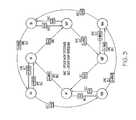
- FIG. 3is a diagram of a first embodiment of a state machine showing the transitions between the four regions of the first and second output signals of FIG. 2 and the updating of signal crossover levels used to define the previous position within a particular region from which the component has moved in a forward (and also in a reverse) direction in determining the distance moved by the component while in the particular region;
- FIG. 4is a block diagram of a second and broad method of the invention.
- FIGS. 1-2illustrate a first method of the invention which is for determining the distance moved by a component (and hence the position of the component) while moving in a forward direction and operatively coupled to an analog encoder having analog first and second output signals 10 and 12 (also known as analog encoder channel A and channel B signals) in substantial quadrature.
- the first methodincludes steps a) through e).
- Step a)is labeled as “Calculate Inverse Signal” in block 14 of FIG. 1 .
- Step a)includes calculating an inverse signal 16 which is the inverse of the second output signal 12 .
- Step b)is labeled as “Calculate Distance Moved In First Region” in block 18 of FIG. 1 .
- Step b)includes calculating the distance moved by the component from a reference position using an ascending region 20 (also known as the first region) of the first output signal 10 until the first output signal 10 reaches a first high level 22 (which may also be called a first high amplitude value, a first high value, or a first high point).
- Step c)is labeled as “Calculate Distance Moved In Second Region” in block 24 of FIG. 1 .
- Step c)includes then calculating the distance moved by the component from the position of the component when the first output signal 10 reached the first high level 22 using an ascending region 26 (also known as the second region) of the second output signal 12 until the second output signal 12 reaches a second high level 28 .
- Step d)is labeled as “Calculate Distance Moved In Third Region” in block 30 of FIG. 1 .
- Step d)includes then calculating the distance moved by the component from the position of the component when the second output signal 12 reached the second high level 28 using a descending region 32 (also known as the third region) of the first output signal 10 until the first output signal 10 reaches a first low level 34 .
- Step e)is labeled as “Calculate Distance Moved In Fourth Region” in block 36 of FIG. 1 .
- Step e)includes then calculating the distance moved by the component from the position of the component when the first output signal 10 reached the first low level 34 using a descending region 38 of the second output signal 12 until the second output signal 12 reaches a second low level 40 after which steps b) through e) are repeated wherein the reference position becomes the position of the component when the second output signal 12 reached the second low level 40 .
- the first high level 22is the crossover level of the ascending first output signal 10 and the inverse signal 16 .
- the second high level 28is the crossover level of the ascending second output signal 12 and the first output signal 10 .
- the first low level 34is the crossover level of the descending first output signal 10 and the inverse signal 16 .
- the second low level 40is the crossover level of the descending second signal 12 and the first output signal 10 .
- the second output signal 12is substantially ninety degrees behind in phase from the first output signal 10 . It is also noted that in FIG. 2 , the x-axis 42 is time and the y-axis 44 is amplitude.
- level 46is assumed to be equal to the first high level 22
- level 48is assumed to be equal to the second low level 40
- level 50is assumed to be equal to the first low level 34 .
- the ascending region 20 of the first output signal 10is between level 48 and the first high level 22
- the ascending region 26 of the second output signal 12is between level 50 and the second high level 28
- the descending region 32 of the first output signal 10is between the second high level 28 and the first low level 34
- the descending region 38 of the second output signal 12is between level 46 and the second low level 40 .
- the crossover level corresponding to the first high level 22is determined from at least one of the current value and the most recent previous value of the first output signal 10 and the inverse signal 16 when it has been determined that the ascending first output signal 10 crossed the inverse signal 16 .
- the first high level 22is a function (such as the average) of the current value and the most recent previous value of the first output signal 10 and the inverse signal 16 .
- the averageis the mean.
- the first high level 22is equal to (i.e., the function is a unity function) the current value or the most recent previous value of the first output signal 10 or the inverse signal 16 .
- Other functions, including other types of averages,are left to the artisan.
- the second high level 28 and the first and second low levels 34 and 40are similarly determined.
- the analog encoderis a rotary analog encoder.
- the analog encoderis a linear analog encoder.
- the analog encoderhas a rotatable encoder wheel, and the first and second high and low levels 22 , 28 , 34 and 40 for one revolution of the encoder wheel are previously measured and previously stored as a map in a memory.
- a printer controllerdetermines the target stopping location of the encoder wheel and the appropriate one or ones of the first and second high and low levels are chosen optimized for the final stopping position and set in a printer ASIC (application specific integrated circuit) and used for calculating distance moved.
- ASICapplication specific integrated circuit
- the first and second high and low levels 22 , 28 34 and 40are updated for changes in crossover levels (i.e., the first and second high and low levels are continuously updated based on the most recent measurements of signal crossovers).
- the componentis a printer paper-feed roller driven by a DC (direct current) motor.
- the componentis a printhead carrier of a printer.
- the ascending regions and descending regions 20 , 26 , 32 and 38are substantially linear regions.
- the first and second output signals 10 and 12are sawtooth signals as shown in FIG. 2 .
- the first and second signalshave rounded peaks and valleys.
- Other illustrations, designs and variationsare left to the artisan.
- FIG. 3is a diagram of a first embodiment of a state machine showing the transitions between the four regions ( 20 , 26 , 32 and 38 ) of the first and second output signals 10 and 12 of FIG. 2 and the updating of signal crossover levels ( 22 , 28 , 34 and 40 ) used to define the previous position within a particular region from which the component has moved in a forward (and also in a reverse) direction in determining the distance moved by the component while in the particular region.
- circle AFstands for forward motion in ascending region 20
- circle BFstands for forward motion in ascending region 26
- circle nAFstands for forward motion in descending region 32
- circle nBFstands for forward motion in descending region 38 .
- circle ARstands for reverse motion in ascending region 20
- circle BRstands for reverse motion in ascending region 26
- nARstands for reverse motion in descending region 32
- circle nBRstands for reverse motion in descending region 38 .
- Ain any rectangular box such as the box containing “A ⁇ B” stands for the first output signal 10
- Bin any rectangular box stands for the second output signal 12
- invBin any rectangular box stands for the inverse signal 16 .
- State machinessuch as the state machine shown in FIG. 3 , are understood by those skilled in the art.
- electronic circuitryinverts the second output signal 12 .
- a printer controllertakes the second output signal 12 and subtracts it from the upper rail of the power supply to create the inversion.
- a printer controllerdetermines the midpoint (mid level) of the second output signal 12 and inverts the signal about the midpoint to create the inversion.
- Other examplesare left to the artisan.
- the second method of the inventionis broader than the previous first method and includes forward and reverse motion and includes changes in crossovers of any appropriate pair of signals (the signals being the first output signal 10 , the second output signal 12 , the inverse signal 16 which is the inverse of the second output signal, and the inverse of the first output signal which is not shown in the figures). It is noted that changes in crossover levels are due to changes in phase and/or amplitude of the signals from whatever cause such as, for example, from encoder resolution limits, encoder signal amplitude reduction at fast speeds, and defects such as inaccurate encoder mounting and ink spots on the encoder.
- one or more or all of the following signal crossover levelsare considered to be variable: level 48 (also shown at a different time as level 40 in FIG. 2 ) when transitioning between region IV (labeled as 38 ) and region I (labeled as 20 ); level 22 and level 50 when transitioning between region I (labeled as 20 ) and region II (labeled as 26 ); level 28 when transitioning between region II (labeled as 26 ) and region III (labeled as 32 ); and level 34 and level 46 when transitioning between region III (labeled as 32 ) and region IV (labeled as 38 ).
- crossover level 50is determined from at least one of the current value and the most recent previous value of the second output signal 12 when transitioning between regions I and II.
- crossover level 46is determined from at least one of the current value and the most recent previous value of the second output signal 12 when transitioning between regions III and IV.
- level 50is assumed to be equal to the first low level 34 with the value representing both levels 50 and 34 updated with the calculated value of level 50 and then with the calculated value for level 34 .
- Other enablementsincluding those using crossovers involving the inverse of the first output signal with or without involving the inverse signal 16 ) and variations and modifications thereof are left to the artisan as well as extensions to analog encoders having three or more output signals.
- the second methodis for determining the distance moved by a component operatively coupled to an analog encoder having analog first and second output signals and includes steps a) and b).
- Step a)is labeled as “Calculate At Least One Inverse Signal” in block 52 of FIG. 4 .
- Step a)includes calculating at least one of a first inverse signal which is the inverse of the first output signal and a second inverse signal which is the inverse of the second output signal.
- Step b)is labeled as “Calculate Distance Moved In A Region” in block 54 of FIG. 4 .
- Step b)includes calculating the distance moved by the component from a previous position using one of an ascending or descending region of the first or second output signal, wherein the previous position is the position of the component corresponding to a crossover level of two signals chosen from the group consisting of the first output signal, the second output signal, and the at-least-one inverse signal.
- the crossover levelis determined from at least one of the current value and the most recent previous value of at least one of the two signals when it has been determined that the two signals crossed.
- the crossover levelis updated each time there is a crossover of the two signals.
- the componentis adapted to move in a forward direction and in a reverse direction.
- the broad methodachieves a more accurate calculation of distance moved from a previous position by having the previous position depend on the crossover level of two of the first and second output and inverse signals instead of on a first or second output signal reaching a fixed high or fixed low crossover level.
- the broad methodis not subject to inaccuracies from phase error between the two output signals and gives improved accuracy from inexpensive analog encoder resolution limits, analog encoder signal amplitude reduction at fast speeds, and defects such as encoder mounting and ink spots on the encoder (e.g., on the encoder wheel for a rotary analog encoder) compared to conventional methods.
Landscapes
- Physics & Mathematics (AREA)
- General Physics & Mathematics (AREA)
- Character Spaces And Line Spaces In Printers (AREA)
Abstract
Description
Claims (12)
Priority Applications (1)
| Application Number | Priority Date | Filing Date | Title |
|---|---|---|---|
| US10/695,235US6963820B2 (en) | 2003-10-28 | 2003-10-28 | Analog encoder method for determining distance moved |
Applications Claiming Priority (1)
| Application Number | Priority Date | Filing Date | Title |
|---|---|---|---|
| US10/695,235US6963820B2 (en) | 2003-10-28 | 2003-10-28 | Analog encoder method for determining distance moved |
Publications (2)
| Publication Number | Publication Date |
|---|---|
| US20050091000A1 US20050091000A1 (en) | 2005-04-28 |
| US6963820B2true US6963820B2 (en) | 2005-11-08 |
Family
ID=34522748
Family Applications (1)
| Application Number | Title | Priority Date | Filing Date |
|---|---|---|---|
| US10/695,235Expired - LifetimeUS6963820B2 (en) | 2003-10-28 | 2003-10-28 | Analog encoder method for determining distance moved |
Country Status (1)
| Country | Link |
|---|---|
| US (1) | US6963820B2 (en) |
Cited By (12)
| Publication number | Priority date | Publication date | Assignee | Title |
|---|---|---|---|---|
| US20060222433A1 (en)* | 2005-03-30 | 2006-10-05 | Brother Kogyo Kabushiki Kaisha | Image Forming Apparatus |
| US20100196075A1 (en)* | 2009-02-02 | 2010-08-05 | Xerox Corporation | Method and system for transmitting proof of payment for "pay-as-you-go" multi-function devices |
| US20100264214A1 (en)* | 2009-04-16 | 2010-10-21 | Xerox Corporation | Method and system for providing contract-free "pay-as-you-go" options for utilization of multi-function devices |
| US20100268591A1 (en)* | 2009-04-16 | 2010-10-21 | Xerox Corporation | System and method for selectively controlling the use of functionality in one or more multifunction devices and subsidizing their use through advertisements |
| US20110191197A1 (en)* | 2010-01-29 | 2011-08-04 | Xerox Corporation | Methods and apparatus for managing credit card usage in pre-paid printing system accounts |
| US20110191212A1 (en)* | 2010-01-29 | 2011-08-04 | Xerox Corporation | System and method for managing consumable return refund processing |
| US20110191183A1 (en)* | 2010-01-29 | 2011-08-04 | Xerox Corporation | Method and apparatus for managing prepaid user initiated advertiser content printing operation at a customer site |
| US20110188068A1 (en)* | 2010-01-29 | 2011-08-04 | Xerox Corporation | Methods and system for consumable validity verification in prepaid document processing devices |
| US20110188067A1 (en)* | 2010-01-29 | 2011-08-04 | Xerox Corporation | Pre-paid document processing devices and operating methods |
| US20110191148A1 (en)* | 2010-01-29 | 2011-08-04 | Xerox Corporation | Methods and apparatus for managing pre-paid printing system accounts |
| US20110191198A1 (en)* | 2010-01-29 | 2011-08-04 | Xerox Corporation | Methods and system for consumable order creation |
| US8886556B2 (en) | 2008-10-06 | 2014-11-11 | Xerox Corporation | System and method for generating and verifying targeted advertisements delivered via a printer device |
Citations (8)
| Publication number | Priority date | Publication date | Assignee | Title |
|---|---|---|---|---|
| US5310272A (en) | 1991-07-22 | 1994-05-10 | Seiko Epson Corporation | Printer timing controller and method |
| US6292117B1 (en)* | 1999-09-01 | 2001-09-18 | Hewlett-Packard Company | Integrated adjustable current to voltage converter and digital quadrature generator in a printer paper positioning system |
| US6330424B1 (en) | 2000-11-21 | 2001-12-11 | Lexmark International, Inc. | Method and apparatus for minimizing the open loop paper positional error in a control system for an electrophotographic printing apparatus |
| US6355927B1 (en)* | 1999-08-20 | 2002-03-12 | Agilent Technologies, Inc. | Interpolation methods and circuits for increasing the resolution of optical encoders |
| US20020037191A1 (en) | 2000-04-27 | 2002-03-28 | Lesniak Christopher M. | Calibration of a media advance system |
| US20020039119A1 (en) | 2000-09-21 | 2002-04-04 | Seiko Epson Corporation | Print control system, print control method, and recording medium having recorded print control program |
| US20030128373A1 (en) | 2002-01-07 | 2003-07-10 | Brother Kogyo Kabushiki Kaisha | Image forming device |
| US6660996B1 (en)* | 2001-07-03 | 2003-12-09 | Lexmark International, Inc. | System and method for examining relationship between intersecting encoder output signals |
- 2003
- 2003-10-28USUS10/695,235patent/US6963820B2/ennot_activeExpired - Lifetime
Patent Citations (10)
| Publication number | Priority date | Publication date | Assignee | Title |
|---|---|---|---|---|
| US5310272A (en) | 1991-07-22 | 1994-05-10 | Seiko Epson Corporation | Printer timing controller and method |
| US5439301A (en) | 1991-07-22 | 1995-08-08 | Seiko Epson Corporation | Printer controller and method thereof for a printhead assembly |
| US6355927B1 (en)* | 1999-08-20 | 2002-03-12 | Agilent Technologies, Inc. | Interpolation methods and circuits for increasing the resolution of optical encoders |
| US6292117B1 (en)* | 1999-09-01 | 2001-09-18 | Hewlett-Packard Company | Integrated adjustable current to voltage converter and digital quadrature generator in a printer paper positioning system |
| US20020037191A1 (en) | 2000-04-27 | 2002-03-28 | Lesniak Christopher M. | Calibration of a media advance system |
| US6454474B1 (en) | 2000-04-27 | 2002-09-24 | Hewlett-Packard Co. | Calibration of a media advance system |
| US20020039119A1 (en) | 2000-09-21 | 2002-04-04 | Seiko Epson Corporation | Print control system, print control method, and recording medium having recorded print control program |
| US6330424B1 (en) | 2000-11-21 | 2001-12-11 | Lexmark International, Inc. | Method and apparatus for minimizing the open loop paper positional error in a control system for an electrophotographic printing apparatus |
| US6660996B1 (en)* | 2001-07-03 | 2003-12-09 | Lexmark International, Inc. | System and method for examining relationship between intersecting encoder output signals |
| US20030128373A1 (en) | 2002-01-07 | 2003-07-10 | Brother Kogyo Kabushiki Kaisha | Image forming device |
Cited By (20)
| Publication number | Priority date | Publication date | Assignee | Title |
|---|---|---|---|---|
| US20060222433A1 (en)* | 2005-03-30 | 2006-10-05 | Brother Kogyo Kabushiki Kaisha | Image Forming Apparatus |
| US8886556B2 (en) | 2008-10-06 | 2014-11-11 | Xerox Corporation | System and method for generating and verifying targeted advertisements delivered via a printer device |
| US20100196075A1 (en)* | 2009-02-02 | 2010-08-05 | Xerox Corporation | Method and system for transmitting proof of payment for "pay-as-you-go" multi-function devices |
| US8205797B2 (en) | 2009-02-02 | 2012-06-26 | Xerox Corporation | Method and system for transmitting proof of payment for “pay-as-you-go” multi-function devices |
| US20100264214A1 (en)* | 2009-04-16 | 2010-10-21 | Xerox Corporation | Method and system for providing contract-free "pay-as-you-go" options for utilization of multi-function devices |
| US20100268591A1 (en)* | 2009-04-16 | 2010-10-21 | Xerox Corporation | System and method for selectively controlling the use of functionality in one or more multifunction devices and subsidizing their use through advertisements |
| US8215548B2 (en) | 2009-04-16 | 2012-07-10 | Xerox Corporation | Method and system for providing contract-free “pay-as-you-go” options for utilization of multi-function devices |
| US20110191198A1 (en)* | 2010-01-29 | 2011-08-04 | Xerox Corporation | Methods and system for consumable order creation |
| US20110188067A1 (en)* | 2010-01-29 | 2011-08-04 | Xerox Corporation | Pre-paid document processing devices and operating methods |
| US20110191148A1 (en)* | 2010-01-29 | 2011-08-04 | Xerox Corporation | Methods and apparatus for managing pre-paid printing system accounts |
| US20110188068A1 (en)* | 2010-01-29 | 2011-08-04 | Xerox Corporation | Methods and system for consumable validity verification in prepaid document processing devices |
| US20110191183A1 (en)* | 2010-01-29 | 2011-08-04 | Xerox Corporation | Method and apparatus for managing prepaid user initiated advertiser content printing operation at a customer site |
| US20110191212A1 (en)* | 2010-01-29 | 2011-08-04 | Xerox Corporation | System and method for managing consumable return refund processing |
| US8271348B2 (en) | 2010-01-29 | 2012-09-18 | Xerox Corporation | Methods and system for consumable order creation |
| US8306877B2 (en) | 2010-01-29 | 2012-11-06 | Xerox Corporation | System and method for managing consumable return refund processing |
| US8332332B2 (en) | 2010-01-29 | 2012-12-11 | Xerox Corporation | Methods and apparatus for managing pre-paid printing system accounts |
| US8542376B2 (en) | 2010-01-29 | 2013-09-24 | Xerox Corporation | Pre-paid document processing devices and operating methods |
| US8650088B2 (en) | 2010-01-29 | 2014-02-11 | Xerox Corporation | Methods and system for managing credit card usage in pre-paid printing system accounts |
| US8873086B2 (en) | 2010-01-29 | 2014-10-28 | Xerox Corporation | Methods and system for consumable validity verification in prepaid document processing devices |
| US20110191197A1 (en)* | 2010-01-29 | 2011-08-04 | Xerox Corporation | Methods and apparatus for managing credit card usage in pre-paid printing system accounts |
Also Published As
| Publication number | Publication date |
|---|---|
| US20050091000A1 (en) | 2005-04-28 |
Similar Documents
| Publication | Publication Date | Title |
|---|---|---|
| US6963820B2 (en) | Analog encoder method for determining distance moved | |
| US9255817B2 (en) | Rotation-angle detection device, image processing apparatus, and rotation-angle detection method | |
| US6556153B1 (en) | System and method for improving encoder resolution | |
| US7711508B2 (en) | Position detector | |
| EP1236973B1 (en) | Method and device for varying interpolation factors | |
| US8912929B2 (en) | Correction value derivation apparatus, displacement amount derivation apparatus, control apparatus, and correction value derivation method | |
| CN111600446B (en) | An encoder for a linear motor, a linear motor and a position detection method thereof | |
| CN1924748B (en) | Image pickup apparatus and method for controlling the same | |
| CN114679100A (en) | Decoding device of sine and cosine encoder, driving equipment and parameter determination method thereof | |
| US6772078B2 (en) | Linear scale reader | |
| JP3026949B2 (en) | Encoder offset correction circuit | |
| US8706269B2 (en) | Controller and machining apparatus with position encoder compensation | |
| JP4868859B2 (en) | Position detection apparatus, position detection method, and image forming apparatus | |
| JP3137552B2 (en) | Absolute encoder | |
| JPH10132605A (en) | Position detector | |
| JP5162739B2 (en) | Encoder signal processing method, encoder device, and servo motor | |
| JP3336396B2 (en) | Absolute encoder | |
| JP2691052B2 (en) | Encoder resolution conversion method and device and image detection device | |
| CN112825470A (en) | Control device for servo motor | |
| JP2008245389A (en) | Motor control apparatus and method | |
| JP2006234697A (en) | Position detection device | |
| CN115077574B (en) | Inductance type absolute value encoder based on environmental induction | |
| JP2893851B2 (en) | Absolute position detection method | |
| KR102167695B1 (en) | Apparatus and method for measuring encoder resolution | |
| CN114356255B (en) | Interpolation table application method and system based on printing process |
Legal Events
| Date | Code | Title | Description |
|---|---|---|---|
| AS | Assignment | Owner name:JACOBS, ELIZABETH C., KENTUCKY Free format text:ASSIGNMENT OF ASSIGNORS INTEREST;ASSIGNORS:ADKINS, CHRISTOPHER ALAN;MARRA, MICHAEL ANTHONY, III;WRITT, JOHN THOMAS;REEL/FRAME:014652/0764 Effective date:20031028 | |
| STCF | Information on status: patent grant | Free format text:PATENTED CASE | |
| FPAY | Fee payment | Year of fee payment:4 | |
| FPAY | Fee payment | Year of fee payment:8 | |
| AS | Assignment | Owner name:LEXMARK INTERNATIONAL, INC., KENTUCKY Free format text:R/F 014652/0764 CORRECTION OF THE NAME OF THE RECEIVING PARTY ON THE RECORDATION COVER SHEET;ASSIGNORS:ADKINS, CHRISTOPHER ALAN;MARRA, MICHAEL ANTHONY, III;WRITT, JOHN THOMAS;REEL/FRAME:032825/0165 Effective date:20031028 | |
| FPAY | Fee payment | Year of fee payment:12 | |
| AS | Assignment | Owner name:CHINA CITIC BANK CORPORATION LIMITED, GUANGZHOU BR Free format text:PATENT SECURITY AGREEMENT;ASSIGNOR:LEXMARK INTERNATIONAL, INC.;REEL/FRAME:046989/0396 Effective date:20180402 | |
| AS | Assignment | Owner name:CHINA CITIC BANK CORPORATION LIMITED, GUANGZHOU BR Free format text:CORRECTIVE ASSIGNMENT TO CORRECT THE INCORRECT U.S. PATENT NUMBER PREVIOUSLY RECORDED AT REEL: 046989 FRAME: 0396. ASSIGNOR(S) HEREBY CONFIRMS THE PATENT SECURITY AGREEMENT;ASSIGNOR:LEXMARK INTERNATIONAL, INC.;REEL/FRAME:047760/0795 Effective date:20180402 | |
| AS | Assignment | Owner name:LEXMARK INTERNATIONAL, INC., KENTUCKY Free format text:RELEASE BY SECURED PARTY;ASSIGNOR:CHINA CITIC BANK CORPORATION LIMITED, GUANGZHOU BRANCH, AS COLLATERAL AGENT;REEL/FRAME:066345/0026 Effective date:20220713 |