US6963572B1 - Method and apparatus for segmentation and reassembly of data packets in a communication switch - Google Patents
Method and apparatus for segmentation and reassembly of data packets in a communication switchDownload PDFInfo
- Publication number
- US6963572B1 US6963572B1US09/426,791US42679199AUS6963572B1US 6963572 B1US6963572 B1US 6963572B1US 42679199 AUS42679199 AUS 42679199AUS 6963572 B1US6963572 B1US 6963572B1
- Authority
- US
- United States
- Prior art keywords
- packet
- segmentation
- received
- cells
- cell
- Prior art date
- Legal status (The legal status is an assumption and is not a legal conclusion. Google has not performed a legal analysis and makes no representation as to the accuracy of the status listed.)
- Expired - Lifetime
Links
- 230000011218segmentationEffects0.000titleclaimsabstractdescription258
- 238000000034methodMethods0.000titleclaimsabstractdescription41
- 238000004891communicationMethods0.000titleabstractdescription15
- 239000004744fabricSubstances0.000claimsabstractdescription80
- 238000012795verificationMethods0.000claimsabstractdescription67
- 238000010926purgeMethods0.000claimsabstractdescription14
- 239000000872bufferSubstances0.000claimsdescription63
- 238000012545processingMethods0.000claimsdescription34
- 230000005540biological transmissionEffects0.000claimsdescription24
- 238000005538encapsulationMethods0.000claimsdescription18
- 230000006870functionEffects0.000claimsdescription15
- 238000011022operating instructionMethods0.000claimsdescription13
- RGNPBRKPHBKNKX-UHFFFAOYSA-NhexaflumuronChemical compoundC1=C(Cl)C(OC(F)(F)C(F)F)=C(Cl)C=C1NC(=O)NC(=O)C1=C(F)C=CC=C1FRGNPBRKPHBKNKX-UHFFFAOYSA-N0.000claimsdescription8
- 238000010586diagramMethods0.000description11
- 238000009432framingMethods0.000description8
- 230000003139buffering effectEffects0.000description7
- 238000012986modificationMethods0.000description4
- 230000004048modificationEffects0.000description4
- 239000013589supplementSubstances0.000description2
- 230000001934delayEffects0.000description1
- 238000001914filtrationMethods0.000description1
- 239000012464large bufferSubstances0.000description1
- 230000007246mechanismEffects0.000description1
- 230000008569processEffects0.000description1
- 230000003252repetitive effectEffects0.000description1
- 230000007480spreadingEffects0.000description1
- 230000002123temporal effectEffects0.000description1
- 238000012546transferMethods0.000description1
Images


Classifications
- H—ELECTRICITY
- H04—ELECTRIC COMMUNICATION TECHNIQUE
- H04L—TRANSMISSION OF DIGITAL INFORMATION, e.g. TELEGRAPHIC COMMUNICATION
- H04L49/00—Packet switching elements
- H04L49/30—Peripheral units, e.g. input or output ports
- H04L49/3081—ATM peripheral units, e.g. policing, insertion or extraction
- H—ELECTRICITY
- H04—ELECTRIC COMMUNICATION TECHNIQUE
- H04Q—SELECTING
- H04Q11/00—Selecting arrangements for multiplex systems
- H04Q11/04—Selecting arrangements for multiplex systems for time-division multiplexing
- H04Q11/0428—Integrated services digital network, i.e. systems for transmission of different types of digitised signals, e.g. speech, data, telecentral, television signals
- H04Q11/0478—Provisions for broadband connections
- H—ELECTRICITY
- H04—ELECTRIC COMMUNICATION TECHNIQUE
- H04L—TRANSMISSION OF DIGITAL INFORMATION, e.g. TELEGRAPHIC COMMUNICATION
- H04L12/00—Data switching networks
- H04L12/54—Store-and-forward switching systems
- H04L12/56—Packet switching systems
- H04L12/5601—Transfer mode dependent, e.g. ATM
- H04L2012/5638—Services, e.g. multimedia, GOS, QOS
- H04L2012/5646—Cell characteristics, e.g. loss, delay, jitter, sequence integrity
- H04L2012/5652—Cell construction, e.g. including header, packetisation, depacketisation, assembly, reassembly
- H—ELECTRICITY
- H04—ELECTRIC COMMUNICATION TECHNIQUE
- H04L—TRANSMISSION OF DIGITAL INFORMATION, e.g. TELEGRAPHIC COMMUNICATION
- H04L12/00—Data switching networks
- H04L12/54—Store-and-forward switching systems
- H04L12/56—Packet switching systems
- H04L12/5601—Transfer mode dependent, e.g. ATM
- H04L2012/5638—Services, e.g. multimedia, GOS, QOS
- H04L2012/5665—Interaction of ATM with other protocols
- H04L2012/567—Frame Relay over ATM
Definitions
- the inventionrelates generally to communication switches and more particularly to a method and apparatus for segmentation and reassembly of data packets in a communication switch.
- Packet-based data communications systemssend data packets through a network of switches in order to relay information included in the packets to a destination.
- Each of the switches in a networkis typically capable of receiving input data from a number of different sources and providing this input data over a number of different outputs towards a number of different destinations.
- Such switchestypically include a number of line cards that perform both reception (ingress data) and transmission (egress data) of the data packets.
- the line cardsare often interconnected using a crossbar switch or similar mechanism such that any ingress data received on any one of the line cards can be provided as egress data on one or more of the other line cards of the switch.
- the packetis typically broken up into cells or other small fixed-data-length structures that are transferred across the backplane, or switching fabric, of the switch to the one or more egress line cards.
- Another disadvantage of prior art systems that require the receipt of the entire packet prior to forwardingis that the latency induced by such systems can significantly delay passage of the packet through the switch. For example, assume that the packet takes 20 microseconds to completely arrive within the ingress portion of the line card. Combining this arrival period with the time required to divide the packet into the fixed-length blocks for transmission across the backplane of the switch can significantly increase the total latency induced by the switch within the communication network. Such additional latency is undesirable, as it can affect overall data transmission speed.
- a further disadvantage of these prior art systems that require receipt of the entire packet prior to forwardingis that the bandwidth available along the backplane of the switch is not optimally utilized. Because in prior art systems the packet is not divided into the fixed-length blocks for transmission across the backplane until the entire packet is received, these fixed-length blocks are typically provided to the backplane in quick succession. Thus, rather than spreading the bandwidth usage for transmission of a packet across a longer period of time, the bandwidth requirements for transmission of the packet grouped temporally. If receipt of a number of different packets is completed at approximately the same time, each of these packets will be attempted to be transmitted across the backplane of the switch in close temporal proximity to the others. This can cause bandwidth usage spikes on the backplane that can increase transmission delays through the switch. Additionally, this can increase the buffering requirements of the ingress portions of the line cards as it may not be possible to transmit data across the backplane as soon as the segmentation, or division into fixed-length blocks, is completed.
- FIG. 1illustrates a block diagram of a segmentation and reassembly circuit in accordance with the present invention
- FIG. 2illustrates a block diagram of segmentation of a packet received in a first format in accordance with the present invention
- FIG. 3illustrates a block diagram of segmentation of a packet received in a second format in accordance with the present invention
- FIG. 4illustrates a block diagram of a portion of a data stream that includes portions of a packet in accordance with the present invention
- FIG. 5illustrates a block diagram of a segmentation processor in accordance with the present invention.
- FIG. 6illustrates a flow diagram of a method for segmenting and forwarding packets in accordance with the present invention.
- the present inventionprovides a method and apparatus for segmenting and forwarding data packets received in a communication switch.
- the methodbegins by receiving a packet that includes fields (e.g. packet destination, packet source, interface, etc.) that determine forwarding parameters.
- fieldse.g. packet destination, packet source, interface, etc.
- segmentation cellsare created from portions of the packet received where each segmentation cell is provided to a switching fabric as soon as creation of the segmentation cell is completed.
- verification of proper receipt of the packetis performed.
- a verification data setis generated based on segmentation cells that have been utilized to forward the packet.
- the verification data setis then included in a final segmentation cell that is provided to the switching fabric.
- Such a verification data setcan then be used by an egress line card that receives the segmentation cells to verify proper receipt of the segmentation cells. If it is determined that the packet has not been successfully received, a purging data set is generated instead of the verification data set. Such a purging data set is then included in the final segmentation cell that is provided to the switching fabric, where the purging data set preferably causes any egress line card to purge the corrupted packet rather than forwarding it.
- the latency and buffering requirements of prior art segmentation and forwarding systemsis greatly reduced. Additionally, the presentation of the segmentation cells to the backplane, or switching fabric, of the switch occurs in a more uniform manner over time such that bandwidth spikes on the backplane are minimized. Verification of the received packet and transmission of a final segmentation cell that indicates proper or improper receipt of the packet ensures that forwarding of an invalid packet by an egress line card does not occur.
- FIG. 1illustrates a segmentation and reassembly circuit 200 that is preferably included within a communication switch. More preferably, the communication switch is an ATM communication switch.
- the segmentation and reassembly circuit 200includes a switching fabric 270 , an ingress line card 210 , and an egress line card 280 .
- the segmentation and reassembly circuit 200is structured such that a plurality of line cards are coupled to the switching fabric 270 where each of the line cards has an ingress and an egress portion.
- any one line cardmay function as the ingress line card for a particular data packet and any other line card may function as the egress line card for such a data packet.
- the segmentation and reassembly circuit 200is included and an ATM switch such that the switching fabric 270 is an ATM backplane included in the ATM switch, and each of the line cards coupled to the ATM backplane is an ATM compatible line card.
- the ingress line card 210which may simply be the ingress portion or ingress block included in a line card, is operably coupled to receive data packets via one or more intput connections.
- FIG. 1illustrates the ingress line card 210 receiving both SONET format packets over a SONET input 260 and ATM cell-based packets over ATM inputs 250 . Packets may also be received in a Frame Relay format.
- the ATM inputs 250are shown to include a plurality of ATM virtual connections (VCs) 251 - 253 , each of which may provide packets to the ingress line card 210 for forwarding.
- VCsATM virtual connections
- Each of the packets received by the ingress line card 210is broken up into a number of segmentation cells that are provided to the switching fabric 270 .
- the switching fabric 270routes each of the segmentation cells to an appropriate destination egress line card 280 where the segmentation cells are reassembled into a packet format and then provided to a destination. Segmentation of the received packet in the ingress block into the segmentation cells that are passed across the switching fabric is preferably accomplished by the segmentation processor 220 that is included and the ingress line card 210 .
- the segmentation processor 220is operably coupled to an ingress context table 230 and an ingress buffer 240 which are provided to support the segmentation.
- the segmentation processorcreates segmentation cells from portions of the packet received. Each of these segmentation cells is provided to the switching fabric 270 as the creation of the segmentation cell is completed. Providing the segmentation cells to the switching fabric as soon as they are created minimizes the size of the ingress buffer 240 as the entire packet is not buffered prior to segmentation.
- the ingress context table 230provides state information to the segmentation processor 220 concerning each of the various packets being received such that proper segmentation and forwarding of the packet is performed.
- the segmentation cellsare fixed-length cells that include a certain amount of payload data allocation. Because the segmentation cells are created as the packet is received, there is often residual payload data resulting from the creation of a segmentation cell. In other words, if a portion of the packet has been received that constitutes slightly more data than a segmentation cell can carry, the segmentation cell will be created with the maximum amount of data it can hold, whereas the remaining packet data is considered residual packet data.
- the residual packet datais stored in the ingress buffer 240 at a location corresponding to the particular packet.
- the amount of residual data stored for a packet and the ingress buffer 240is described using an ingress buffer count, whereas the location of the residual data for the packet is described using a corresponding ingress buffer index.
- the ingress buffer index and corresponding ingress buffer count for each packetare included in the state information, or ingress status information, for that packet as stored in the ingress context table 230 .
- the segmentation processor 220when the segmentation processor 220 receives a portion of a particular packet it references the ingress context table 230 to determine the current forwarding state of that packet. Based on this, the segmentation processor 220 can retrieve any residual data for that packet from the ingress buffer 240 . This residual data that has been retrieved can then be combined with at least a portion of the newly received packet data for creation of a segmentation cell for transmission across the switching fabric. Any resulting residual packet data is then stored in the ingress buffer 240 based on the ingress buffer index, and the current ingress buffer count, as stored and the ingress context table 230 , is updated to reflect the current amount of residual data for that particular packet stored and the ingress buffer 240 .
- the segmentation of a packet into segmentation cells and the storage of the residual portions of the packetcan be better understood with reference to FIGS. 2 and 3 which are discussed with additional detail below.
- the segmentation processor 220verifies that the packet has been successfully received by the ingress block. Once this has been accomplished, the segmentation processor 220 generates a destination decision for the packet, where the destination decision is included in a final segmentation cell provided to the switching fabric. The destination may have been determined when the first portion of the packet was received and pre-pended to the packet as well. Essentially, the destination decision determines what the egress line card does with the segmentation cells that it has received thus far for a particular packet.
- the egress line cardreceives a destination decision that indicates that the packet was received successfully by the ingress line card, and also is able to verify the transmission across the switching fabric has occurred properly, the egress line card can then forward that packet to a destination connection. If the destination decision indicates that the packet was incorrectly received by the ingress line card, the segmentation cells received thus far by the egress line card are deemed invalid, and therefore are preferably purged rather than provided to a output connection.
- Verification of proper receipt of a packet by the segmentation processor 220can occur in a variety of ways.
- a length parameteris included in the final portion of each packet.
- the segmentation processor 220can compare this length parameter with the length of the packet received to verify that the length of the packet received is correct. This can be accomplished by maintaining a current ingress length parameter for each packet in the ingress status information stored in the ingress context table 230 . Such an ingress length parameter is updated based on received portions of the packet such that it contains the current length of the packet as received.
- the length parameter included in the end portion of the packetcan be compared with the current ingress length stored in the ingress context table 230 to determine if the length of the packet as received is correct.
- a cyclical redundancy check valueis included in the end portion of each packet.
- the cyclical redundancy check (CRC) technique for data transmission verificationis well known in the art.
- a current ingress CRC valuecan be maintained in the ingress status information stored in the ingress context table 230 in a similar manner to the ingress length value described above for each packet.
- the received CRC valuecan be compared with the current ingress CRC value stored in the ingress context table 230 to verify proper receipt of the packet.
- each of the segmentation cellsis created such that each segmentation cell includes an internal encapsulation format that facilitates transfer of the segmentation cells across the switching fabric.
- each of the segmentation cellsis an ATM cell that includes ATM header information to promote proper forwarding of the ATM cell across the switching fabric, which is an ATM backplane.
- the packet encapsulationis removed by the egress line card, as the egress line card has to modify the encapsulation information anyway.
- the ingress line cardpreferably identifies the number of bytes of encapsulation that need to be removed and includes this information in the final cell. This simplifies the hardware required to perform the frame modification at the minimal additional cost of the extra data being passed across the switching fabric.
- the encapsulation configuration of the packetis preferably stored in the ingress context table, which enables the segmentation processor 220 to properly isolate the packet. Additionally, the ingress context table 230 may store the forwarding decision information for each packet such that forwarding of the packet across the backplane of the switch is performed without having any repetitive determination of the forwarding information occur.
- a current switching fabric egress CRC and current egress length value for each packetmay also be included in the ingress status information for the packet in the ingress context table 230 .
- These egress valuescorrespond to the CRC and length values that apply to the segmentation cells that have been provided to the switching fabric for a particular packet.
- the current egress CRC and egress length valuescan be included in the final segmentation cell such that they can be utilized by the egress line card for verification of internal transmission of the packet within the switch 200 .
- the CRC and length values that are sent over the switching fabric to the egress linecardmay either be re-calculated by the segmentation processor from scratch or may be derived from the original packet CRC (received CRC) and length value (received length). If the verification CRC sent over the switching fabric is derived from the received CRC, any changes to the packet (encapsulation, routing information, etc.) will be reflected in delta values included with the verification CRC, thus allowing verification of the packet as altered. Therefore, the verification CRC is produced by modifying the received CRC such that the verification CRC is valid for the packet as provided to the switching fabric. Similarly, the verification length parameter sent across the switching fabric would reflect the length of the packet as it is provided to the switching fabric.
- the egress line card 280which may simply be an egress block included in a line card within the switch 200 , receives the segmentation cells from the switching fabric 270 .
- the egress line card 280then reassembles the packet to produce a reassembled packet from the segmentation cells. This reassembled packet is then forwarded based on at least portion of the forwarding parameters that were included with the packet as received by the ingress line card 210 .
- the egress line cardincludes an egress buffer 310 , an egress context table 300 , and a reassembly processor 290 .
- the egress buffer 310stores packets being reassembled where each packet being reassembled has a corresponding egress buffer index and a corresponding egress buffer count. Received segmentation cells for a packet being reassembled are stored in the buffer based on the corresponding egress buffer index and the egress buffer count of the packet being reassembled. The received segmentation cells may also be stored as linked lists of cells. Thus, as portions of a packet are received via segmentation cells, the packet is gradually reconstructed in the egress buffer from the segmentation cells received.
- the egress buffer indexindicates a reference point for the particular packet within the egress buffer, and the egress buffer index indicates the location where the next portion of the packet should be stored in order to further reassembly of the packet.
- the egress context table 300stores egress status information for each of the packets being reassembled in the egress line card 280 .
- the status information for each packetincludes its egress buffer index and its egress buffer count. Additional status information may include CRC and length values corresponding to portions of the packet thus far received, along with any destination or forwarding decision information or encapsulation information regarding the particular packet. Such status information can be used to verify receipt of a packet from an ingress line card over the switching fabric 270 . The status information can also be used to determine how the particular packet is to be provided to one of the outputs of the egress line card.
- the reassembly processor 290is operably coupled to the egress buffer and the egress context table, and the reassembly processor control storage of the segmentation cells for the packet in the egress buffer based on the status information for the packet in the egress context table.
- the reassembly processormay perform functions such as stripping off any internal encapsulation required to forward the portions of the packet included in the segmentation cells through the switching fabric 270 .
- the reassembly processorforwards the reassembled packet via an output connection 312 determined based on the forwarding parameters for the packet.
- forwarding of a reassembled packetdoes not occur until the entire packet has been reassembled in the egress buffer 310 . This ensures that there is no intermingling of portions of multiple packets across a single virtual output connection. The intermingling of portions of packets is undesirable as it corrupts any such intermingled packets and invalidates their transmission.
- a packethas been reassembled, it is forwarded in a continuous format over a particular output connection.
- FIG. 2illustrates a block diagram of a packet 320 received in a first format.
- the first formatis analogous to a packet over SONET format, which is known in the art.
- the packet 320is delivered in a frame that includes initial framing data 322 and final framing data 332 .
- Such framing datais preferably stripped off by the segmentation processor 220 of the ingress line card 210 .
- the segmentation processor 220determines when a sufficient portion of the packet 320 has been received to create a first segmentation cell 344 .
- the first segmentation cell 344includes any required internal framing data 342 and a payload, or data portion illustrated as data portion A 324 .
- the data portion Ais a portion of the packet 320 .
- the size of the portionis based on the size of the internal framing data 342 such that the first segmentation cell 344 is filled.
- the first segmentation cell 344only includes the data portion A 324 , more data for the packet 320 may have been received. However, if the additional data for the packet 320 is insufficient to create the second segmentation cell 346 , it will be buffered until a sufficient portion of the packet 320 has been received to generate the second segmentation cell 346 . Thus, the ingress context table 230 may be referenced to determine the ingress buffer index and ingress buffer count for the packet 320 such that any residual portion of the packet can be stored in the ingress buffer 240 . Once an additional portion of the packet 320 has been received that is sufficient to generate the second segmentation cell 346 , the data portion B 326 is included in the second segmentation cell 346 which is then provided to the switching fabric 270 . Note that the second segmentation cell 346 may include data that has recently been received and data that has been stored as a residual portion of a previously received portion of the packet 320 .
- the data portion C 328 of the packet 320will be broken up into a number segmentation cells that are transmitted as creation of each of the segmentation cells is completed.
- the packet 320When the final data portion D 330 of the packet 320 is received, it is included in the final segmentation cell 348 .
- the packet 320may be accompanied by verification data such as a length parameter and a CRC parameter. If these parameters are included in the packet 320 , a verification procedure can compare the CRC length or any other verification parameters with current stored parameters that are included in the ingress context table 230 for the packet.
- the final segmentation cell 348also includes the destination decision, or valid indication 350 that indicates whether or not the packet 320 has been properly received by the ingress line card 210 . If the valid indication 350 indicates that the packet 320 has been properly received, the egress line card forwards the packet to its destination under the assumption that it is properly transmitted across the switching fabric. If the valid indication 350 indicates that the packet was incorrectly received, the egress line card 280 will purge the packet 320 rather than forward it in its corrupted state.
- a CRC value 354 and/or a length value 352may be included in the final segmentation cell 348 .
- the CRC value 354 and length value 352can be utilized to verify transmission of the segmentation cells through the switching fabric as was described earlier.
- some padding information 351may be included in the final segmentation cell 348 .
- the padding information 351is merely a placeholder and is typically discarded upon receipt by the egress line card 280 . Note that the padding may not be required in systems where variable length cells are supported. Note that the ordering of the various portions of the final segmentation cell 348 may be modified based on specific implementation.
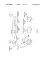
- FIG. 3illustrates a block diagram of the segmentation of a packet 360 that is constructed through the receipt of a number of cells 362 - 368 .
- the received cells 362 - 368are ATM cells, however any cell-based communication connection may provide the packet 360 in such a manner.
- the packet 360is typically received in a format that includes some initial framing data 361 and final framing data 369 .
- the final framing datamay include a CRC value, a length value, or another means of verifying proper receipt of the packet 360 .
- the cells 362 - 368may be received via a plurality of virtual connections that supply the packet to the ingress line card 210 , or they may be provided over a single virtual connection.
- FIG. 4illustrates a potential data stream 255 that includes the cells 362 - 368 carrying portions of the packet 360 .
- the cells 362 - 368 that include packet portionsare interspersed with other cells carrying portions of other packets 257 .
- the cells 362 - 368may be spaced apart by a significant amount of time. In prior art systems, this would result in the requirement for buffering large received portions of the packet 360 until the entire packet was received. This could be especially troublesome for packets being transferred using lower qualities of transmission service, where these qualities of service may not receive the necessary bandwidth to provide the entire packet to the ingress line card in a timely manner.
- segmentation cells 382 - 386are generated to carry the packet information through the switching fabric 270 .
- the first segmentation cell 382will be generated when a sufficient portion of the packet 360 has been received such that the destination for the packet can be determined and enough payload portion of the packet 360 has been received to fill the remainder of the first segmentation cell 382 .
- the segmentation cells generatedare preferably of a fixed size.
- the first segmentation cell data 374 that is included in the first segmentation cell 382is illustrated to come from portions of the initial received cell 362 and the second received cell 364 . This is because the portion of the first segmentation cell data 374 in the initial received cell 362 is inadequate to fill the payload capacity of the first segmentation cell 382 .
- the second received cell 364is received, a portion of the information in that cell is used to supplement the data from the initial received cell 362 to generate the first segmentation cell data 374 .
- This datais then included in the first segmentation cell 382 , and as creation of the first segmentation cell 382 is completed, the first segmentation cell is provided to the switching fabric for transmission through the switch.
- the remaining portion of the second received cell 364 that was not included in the first segmentation cell data 374is stored in the ingress buffer 240 based on information contained in the ingress context table 230 as illustrated and described with respect to FIG. 1 . Note that this residual data will be stored until the third received cell 366 is received. At this time, the residual portion of the second received cell 364 will be retrieved from the ingress buffer 240 and combined with a portion of the third received cell 366 to form the second segmentation cell data set 376 which is included in the second segmentation cell 384 . Once again, any residual portion of the third received cell 366 is stored in the ingress buffer 240 in anticipation of the generation of subsequent segmentation cells as additional received cells are received.
- the data portion of the final received cellis combined with any residual data stored in the ingress buffer 240 . It is then determined whether or not this combined data set can be included in the final segmentation cell 386 . In the event where the residual portion stored in the ingress buffer 240 that is combined with the data in the final received cell 368 exceeds the payload capacity of the final segmentation cell 386 , a segmentation cell will be generated that includes as much of the remaining payload data as can be included in a segmentation cell. The final segmentation cell data 378 that is left over is then placed in the final segmentation cell 386 .
- the final segmentation cell 386may also include a CRC value 398 , a length value 396 , and a valid indication 394 , where the valid indication indicates valid receipt of the packet 360 by the ingress line card, and the CRC and length values 398 and 396 can be used to verify transmission of the segmentation cells through the switching fabric 270 . Additional padding 392 is included in the final cell 386 such that the final segmentation cell is filled.
- the final segmentation cell 386can be used by the egress line card, or egress line cards in the case of a multi-cast packet, for verification of the packet 360 .
- the packet 360will then be fully assembled in the egress line card and, if valid reception of the packet has occurred, the packet will be re-encapsulated in a proper output format and provided to an output of the egress line card.
- FIG. 6illustrates a flow diagram of a method for segmenting and forwarding packets.
- the methodmay be performed through the execution of a software algorithm, and such a software algorithm may be executed using a segmentation processor 150 as illustrated in FIG. 5 .
- the segmentation processor 150includes a processing module 152 and memory 154 .
- the processing module 152may be a single processing device or a plurality of processing devices.
- Such a processing devicemay be a microprocessor, microcontroller, digital signal processor, microcomputer, state machine, logic circuitry, and/or any device that processes information based on operational and/or programming instructions.
- the memory 154may be a single memory device or a plurality of memory devices. Such a memory device may be a read only memory device, random access memory device, floppy disk, hard drive memory, and/or any device that stores digital information. Note that when the processing module 152 has one or more of its functions performed by a state machine and/or logic circuitry, the memory containing the corresponding operational instructions is embedded within the state machine and/or logic circuitry.
- the memory 154stores programming and/or operating instructions that, when executed, allow the processing module 152 to perform at least a portion of the steps of the method illustrated in FIG. 6 .
- segmentation processor 150may implement some of the functions of this method through software stored in the memory 154 , whereas other portions may be implemented using hardware, or circuitry included within the segmentation processor 150 . Thus, in some embodiments a mix of hardware and software may be used to perform the method of FIG. 6 .
- FIG. 6illustrates a flow diagram of a method for segmenting and forwarding packets in a communication system, which is preferably a switch included within a communications network. More preferably, the method is employed within a network switch that receives packets in a format such as an ATM cell-based format, a Frame Relay format, a packet over SONET format, or any other packet- or cell-based network.
- a formatsuch as an ATM cell-based format, a Frame Relay format, a packet over SONET format, or any other packet- or cell-based network.
- the methodbegins at step 102 where a packet is received that includes fields that specify at least destination forwarding parameters.
- the fieldsmay specify a source IP address, a destination IP address, the type of service, the protocol, and upper layer ports that are used to determine the destination forwarding parameters.
- the destination forwarding parametersmay include the output line card, port, or Virtual Connection Identifier (VCI) to which the packet is to be directed. At least a portion of this information must be relayed to the egress line card. Typically, the port information is always relayed. In ATM systems the VCI is included, and in frame relay the DLCI is included.
- the packet received at step 102may be received as shown in step 104 as a plurality of ATM cells. Note that these ATM cells may be received spaced out over time over one or more virtual connections as is indicated in step 108 . In another embodiment, the packet is received as illustrated in step 106 in a packet over SONET format.
- segmentation cellsare created from portions of the packet received. Preferably these segmentation cells are created as soon as adequate data for their creation is received. Examples illustrated in FIGS. 2 and 3 for packets 320 and 360 are good examples of the creation of segmentation cells from packets in different formats. Creating a segmentation cell at step 110 may further include encapsulating the segmentation cells in order to adapt them for transmission within the switching fabric to which they are supplied once their creation is complete.
- the first segmentation cell createdis created as soon as adequate forwarding information for the packet is received and enough packet data to fill the payload of the first segmentation cell has also been received.
- any residual portion of the packet not included in segmentation cellis stored, at step 112 , in a buffer for inclusion in subsequent segmentation cells. This residual portion will then be combined with subsequently received portions of the packet to create the subsequent segmentation cells.
- any residual portion of the packet resulting from the creation of any of these subsequent segmentation cellsis stored in the buffer until it can be used with further portions of the packet received to generate further segmentation cells.
- a buffer location for the packetis preferably fetched from a context table.
- the residual portion of the packetis then stored in the buffer based on the buffer location and a current buffer count that is also preferably stored in the context table. Once the residual portion of the packet is stored within the buffer, the current buffer count is updated to reflect storage of the residual portion in the buffer such that it can be retrieved for use in generating subsequent segmentation cells.
- the context table for a particular packetmay also be used to determine the current forwarding status of the packet and to store length and CRC values for the packet as it is received such that when the entire packet has been received verification of these values is possible. Furthermore, the context table can be used to store length and CRC values for the segmentation cells that have been assembled and forwarded across the backplane such that verification of the internal transmission of the packet within the switch is possible. This is described with respect to steps 128 - 132 below.
- each segmentation cellis provided to the switching fabric as creation of the segmentation cell is completed. Preferably this is done with minimal delay such that latency through the switch is minimized.
- the switching fabric to which the segmentation cell is suppliedis a backplane of a fixed-transfer-length switch, where the backplane intercouples a plurality of fixed-transfer-length line cards.
- the segmentation cells generated at step 110are preferably fixed length segmentation cells adapted for transmission through the switching fabric. More preferably, the segmentation cells generated are ATM segmentation cells where the switching fabric is a backplane of an ATM switch. In such an embodiment, the backplane intercouples a plurality of ATM line cards where the ATM segmentation cells facilitate forwarding of packets amongst the plurality of ATM line cards.
- step 116it is determined whether or not the end of the packet has been received. If not, the method repeats steps 110 and 114 such that subsequent segmentation cells are created and provided to the switching fabric as the packet continues to arrive. Once the end of the packet has been received, the method proceeds to step 118 .
- step 118verification of receipt of the packet is performed. This can include one or more of steps 120 and 122 .
- step 120the length of the packet as received is verified.
- the packetwill include a length parameter that is checked with a length parameter maintained in the context table for the packet.
- the length parameter in the context tableis updated as the packet is received such that when the end of the packet has been received, the length parameter in the table stores a length value that can be compared with the length parameter included in the packet.
- a cyclical redundancy check(CRC) is used to verify receipt of the packet. Verification of packets through CRC checks is well known in the art.
- a running CRC value for the packetcan be maintained in the context table entry for the packet such that a final CRC value is available at the end of the packet for comparison with a CRC value included in the packet.
- step 124it is determined whether or not the packet was or was not received successfully. This is determined based on the verification performed at step 118 . If the packet was not received successfully, a purging data set is generated at step 126 . This purging data set is included in the final segmentation cell provided to the switching fabric. The final segmentation cell also preferably includes at least a portion of the destination forwarding parameters (as described above with respect to step 102 ) and may further include billing account numbers. Upon receipt by the egress line card, or other receiving entity of the final segmentation cell, the purging data set preferably instructs the receiving entity to discard the entire packet as an unsuccessfully received packet was transferred across the backplane and should not be forwarded any further.
- step 124If it is determined at step 124 that the packet has been received successfully, the method proceeds to step 128 where a verification data set is generated.
- the verification data setsimply informs the egress line card that the packet was successfully received by the ingress line card, and therefore may be forwarded towards its final destination. This may be accomplished with a valid bit or bit field.
- the verification data setis more complex and is generated based on the segmentation cells used to forward the packet. Such a verification data set is then included in the final segmentation cell as it will allow the destination entity, or egress line card, to verify proper transmission of the segmentation cells through the switching fabric.
- the verification data setincludes a verification length parameter as shown in step 130 and/or a verification CRC parameter as illustrated in step 132 .
- the verification length parameteris maintained, preferably in the context table for the packet, to reflect length of the packet as the segmentation cells are created and provided to the switching fabric.
- the final value of the verification length parameteris known and can be included in the final segmentation cell.
- the verification CRCcan be maintained using a running CRC value that is stored in the context table for the packet, where the running CRC value is updated as segmentation cells are created and provided to the switching fabric.
- a final value of the running CRC valueindicates the verification CRC value that is included in the final segmentation cell.
- the segmentation cells generated at step 112 and provided to the switching fabric at step 114are used to reassemble the packet that is then forwarded to an output of the egress line card.
- the method for performing this reassembly and forwardingis preferably as was described with respect to the egress line card 280 of FIG. 1 .
- Such methodologymay be implemented in a reassembly processor analogous to the segmentation processor 150 illustrated in FIG. 5 .
- the reassembly processormay include a processing module and memory that executes software instructions to perform the reassembly operations as were described with respect to FIG. 1 .
- Utilization of the method and apparatus described hereinallows for segmentation and forwarding of packets in a data communications system with reduced requirements for buffering memory and reduced latency. This is accomplished by removing need to buffer an entire packet prior to segmentation and forwarding. By segmenting the packet as it is received and forwarding the segments as soon as they are created, the latency through the switch is reduced and the need for large buffers in the ingress line cards is greatly reduced.
Landscapes
- Engineering & Computer Science (AREA)
- Computer Networks & Wireless Communication (AREA)
- Signal Processing (AREA)
- Data Exchanges In Wide-Area Networks (AREA)
Abstract
Description
Claims (32)
Priority Applications (4)
| Application Number | Priority Date | Filing Date | Title |
|---|---|---|---|
| US09/426,791US6963572B1 (en) | 1999-10-22 | 1999-10-22 | Method and apparatus for segmentation and reassembly of data packets in a communication switch |
| DE60028498TDE60028498T2 (en) | 1999-10-22 | 2000-10-19 | Method and apparatus for segmentation and reassembly of packets in a communications broker |
| EP00122791AEP1094641B1 (en) | 1999-10-22 | 2000-10-19 | Method and apparatus for segmentation and reassembly of data packets in a communication switch |
| US11/269,251US7463650B2 (en) | 1999-10-22 | 2005-11-07 | Method and apparatus for segmentation and reassembly of data packets in a communication switch |
Applications Claiming Priority (1)
| Application Number | Priority Date | Filing Date | Title |
|---|---|---|---|
| US09/426,791US6963572B1 (en) | 1999-10-22 | 1999-10-22 | Method and apparatus for segmentation and reassembly of data packets in a communication switch |
Related Child Applications (1)
| Application Number | Title | Priority Date | Filing Date |
|---|---|---|---|
| US11/269,251DivisionUS7463650B2 (en) | 1999-10-22 | 2005-11-07 | Method and apparatus for segmentation and reassembly of data packets in a communication switch |
Publications (1)
| Publication Number | Publication Date |
|---|---|
| US6963572B1true US6963572B1 (en) | 2005-11-08 |
Family
ID=23692222
Family Applications (2)
| Application Number | Title | Priority Date | Filing Date |
|---|---|---|---|
| US09/426,791Expired - LifetimeUS6963572B1 (en) | 1999-10-22 | 1999-10-22 | Method and apparatus for segmentation and reassembly of data packets in a communication switch |
| US11/269,251Expired - Fee RelatedUS7463650B2 (en) | 1999-10-22 | 2005-11-07 | Method and apparatus for segmentation and reassembly of data packets in a communication switch |
Family Applications After (1)
| Application Number | Title | Priority Date | Filing Date |
|---|---|---|---|
| US11/269,251Expired - Fee RelatedUS7463650B2 (en) | 1999-10-22 | 2005-11-07 | Method and apparatus for segmentation and reassembly of data packets in a communication switch |
Country Status (3)
| Country | Link |
|---|---|
| US (2) | US6963572B1 (en) |
| EP (1) | EP1094641B1 (en) |
| DE (1) | DE60028498T2 (en) |
Cited By (20)
| Publication number | Priority date | Publication date | Assignee | Title |
|---|---|---|---|---|
| US20020136229A1 (en)* | 2001-01-09 | 2002-09-26 | Lucent Technologies, Inc. | Non-blocking crossbar and method of operation thereof |
| US20030041163A1 (en)* | 2001-02-14 | 2003-02-27 | John Rhoades | Data processing architectures |
| US20030118052A1 (en)* | 2001-12-21 | 2003-06-26 | Kuhl Timothy Harris | System and method for reassembling packets in a network element |
| US20040004964A1 (en)* | 2002-07-03 | 2004-01-08 | Intel Corporation | Method and apparatus to assemble data segments into full packets for efficient packet-based classification |
| US20040090957A1 (en)* | 2002-04-19 | 2004-05-13 | Alcatel | Centralized switching and routing packet handling device |
| US20040228355A1 (en)* | 2000-03-30 | 2004-11-18 | Azanda Network Devices, Inc. | Methods and apparatus for dynamically allocating bandwidth between ATM cells and packets |
| US20050047377A1 (en)* | 2001-05-07 | 2005-03-03 | Odenwalder Joseph P. | Method and apparatus for generating control information for packet data |
| US20050129031A1 (en)* | 2003-12-10 | 2005-06-16 | Robotham Robert E. | Method and apparatus for providing combined processing of packet and cell data |
| US20060248102A1 (en)* | 2005-05-02 | 2006-11-02 | Michael Bowler | Adaptive pre-fragmentation and pre-segmentation system and method |
| US7142564B1 (en)* | 2001-02-07 | 2006-11-28 | Cortina Systems, Inc. | Multi-service segmentation and reassembly device with a single data path that handles both cell and packet traffic |
| US7286565B1 (en)* | 2000-06-28 | 2007-10-23 | Alcatel-Lucent Canada Inc. | Method and apparatus for packet reassembly in a communication switch |
| US20070294378A1 (en)* | 2006-06-06 | 2007-12-20 | Christian Olgaard | Method for capturing multiple data packets in a data signal for analysis |
| US20080172588A1 (en)* | 2006-06-06 | 2008-07-17 | Litepoint Corp. | System and method for testing multiple packet data transmitters |
| US20080285467A1 (en)* | 2006-04-14 | 2008-11-20 | Litepoint Corp. | Apparatus, System and Method for Calibrating and Verifying a Wireless Communication Device |
| US20090043650A1 (en)* | 2007-08-08 | 2009-02-12 | Legalforce, Inc. | Segmented services having a global structure of networked independent entities |
| US7796625B2 (en) | 2007-01-10 | 2010-09-14 | International Business Machines Corporation | Recovery flushing for a network packet dispatcher |
| US20110090799A1 (en)* | 2009-10-19 | 2011-04-21 | Litepoint Corporation | System and method for testing multiple digital signal transceivers in parallel |
| CN105451569A (en)* | 2013-08-02 | 2016-03-30 | 马斯公司 | Brown anthocyanin-containing colorant |
| US11080303B2 (en)* | 2017-09-08 | 2021-08-03 | Bank Of America Corporation | System and method of multiprotocol publisher and subscriber services |
| WO2022206759A1 (en)* | 2021-03-31 | 2022-10-06 | 华为技术有限公司 | File sending method, device and computer readable storage medium |
Families Citing this family (19)
| Publication number | Priority date | Publication date | Assignee | Title |
|---|---|---|---|---|
| KR100476455B1 (en)* | 2003-01-03 | 2005-03-18 | 삼성전자주식회사 | Apparatus for N:1 Redundancy of voice processing unit in media gateway system and method thereof |
| JP4567373B2 (en)* | 2004-05-20 | 2010-10-20 | ルネサスエレクトロニクス株式会社 | Data transfer device and communication data processing system |
| US20060248375A1 (en)* | 2005-04-18 | 2006-11-02 | Bertan Tezcan | Packet processing switch and methods of operation thereof |
| US7636357B2 (en)* | 2006-04-27 | 2009-12-22 | Alcatel Lucent | Method of collecting consistent flow statistics through multiple congestion points within a multi-service switch/router and multi-service switches/routers provisioned with same |
| US7817652B1 (en) | 2006-05-12 | 2010-10-19 | Integrated Device Technology, Inc. | System and method of constructing data packets in a packet switch |
| US7747904B1 (en) | 2006-05-12 | 2010-06-29 | Integrated Device Technology, Inc. | Error management system and method for a packet switch |
| US7596142B1 (en)* | 2006-05-12 | 2009-09-29 | Integrated Device Technology, Inc | Packet processing in a packet switch with improved output data distribution |
| US7706387B1 (en) | 2006-05-31 | 2010-04-27 | Integrated Device Technology, Inc. | System and method for round robin arbitration |
| US7693040B1 (en) | 2007-05-01 | 2010-04-06 | Integrated Device Technology, Inc. | Processing switch for orthogonal frequency division multiplexing |
| US20090144493A1 (en)* | 2007-11-30 | 2009-06-04 | Microsoft Corporation | Circular Buffer Maping |
| KR101476813B1 (en)* | 2007-11-30 | 2014-12-29 | 삼성전자주식회사 | System and method for packet reassembly of packet relay node |
| JP5286944B2 (en) | 2008-05-30 | 2013-09-11 | 富士通セミコンダクター株式会社 | Receiving apparatus and packet communication method |
| DE602008006234D1 (en) | 2008-12-19 | 2011-05-26 | Alcatel Lucent | Scalable network element with segmentation and recombination function (SAR) for switching time-multiplexed signals |
| CN101895398B (en)* | 2010-07-15 | 2012-07-25 | 华为技术有限公司 | Method and device for data communication |
| US8780931B2 (en) | 2011-05-14 | 2014-07-15 | International Business Machines Corporation | Multi-role distributed line card |
| US8982905B2 (en) | 2011-05-16 | 2015-03-17 | International Business Machines Corporation | Fabric interconnect for distributed fabric architecture |
| US8773999B2 (en) | 2011-10-26 | 2014-07-08 | International Business Machines Corporation | Distributed chassis architecture having integrated service appliances |
| US8855127B2 (en)* | 2012-10-02 | 2014-10-07 | Lsi Corporation | Method and system for intelligent deep packet buffering |
| US8949487B1 (en)* | 2013-07-29 | 2015-02-03 | Western Digital Technologies, Inc. | Data transmission from data storage device |
Citations (22)
| Publication number | Priority date | Publication date | Assignee | Title |
|---|---|---|---|---|
| US5420858A (en)* | 1993-05-05 | 1995-05-30 | Synoptics Communications, Inc. | Method and apparatus for communications from a non-ATM communication medium to an ATM communication medium |
| US5430727A (en) | 1990-09-04 | 1995-07-04 | Digital Equipment Corporation | Multiple protocol routing |
| US5509123A (en) | 1994-03-22 | 1996-04-16 | Cabletron Systems, Inc. | Distributed autonomous object architectures for network layer routing |
| US5568477A (en)* | 1994-12-20 | 1996-10-22 | International Business Machines Corporation | Multipurpose packet switching node for a data communication network |
| US5777984A (en)* | 1996-04-01 | 1998-07-07 | Motorola Inc. | Method and apparatus for controlling cell transmission rate in a cell based network in the presence of congestion |
| US5818842A (en)* | 1994-01-21 | 1998-10-06 | Newbridge Networks Corporation | Transparent interconnector of LANs by an ATM network |
| GB2324676A (en) | 1997-04-23 | 1998-10-28 | Fujitsu Ltd | Interfacing to SAR devices in ATM switching apparatus |
| US5905723A (en) | 1993-06-23 | 1999-05-18 | Cabletron Systems, Inc. | System for achieving scalable router performance |
| WO1999027688A1 (en) | 1997-11-24 | 1999-06-03 | Ascend Communications, Inc. | Method and apparatus for performing cut-through virtual circuit merging |
| US5918022A (en) | 1998-09-28 | 1999-06-29 | Cisco Technology, Inc. | Protocol for transporting reservation system data over a TCP/IP network |
| US6075788A (en)* | 1997-06-02 | 2000-06-13 | Lsi Logic Corporation | Sonet physical layer device having ATM and PPP interfaces |
| US6078963A (en)* | 1998-01-16 | 2000-06-20 | At&T Corp. | Router with de-centralized processing using intelligent ports |
| US6081512A (en) | 1997-06-30 | 2000-06-27 | Sun Microsystems, Inc. | Spanning tree support in a high performance network device |
| US6160811A (en)* | 1997-09-12 | 2000-12-12 | Gte Internetworking Incorporated | Data packet router |
| US6212185B1 (en) | 1998-10-14 | 2001-04-03 | Nortel Networks Corporation | Multiple network address resolution |
| US6259699B1 (en)* | 1997-12-30 | 2001-07-10 | Nexabit Networks, Llc | System architecture for and method of processing packets and/or cells in a common switch |
| US6307860B1 (en)* | 1998-04-03 | 2001-10-23 | Mmc Networks, Inc. | Systems and methods for data transformation and transfer in networks |
| US6363053B1 (en) | 1999-02-08 | 2002-03-26 | 3Com Corporation | Method and apparatus for measurement-based conformance testing of service level agreements in networks |
| US6370142B1 (en) | 1995-07-12 | 2002-04-09 | Nortel Networks Limited | Method and apparatus for performing per-port IP multicast pruning |
| US6374303B1 (en) | 1997-11-17 | 2002-04-16 | Lucent Technologies, Inc. | Explicit route and multicast tree setup using label distribution |
| US6463067B1 (en)* | 1999-12-13 | 2002-10-08 | Ascend Communications, Inc. | Submission and response architecture for route lookup and packet classification requests |
| US6487170B1 (en) | 1998-11-18 | 2002-11-26 | Nortel Networks Limited | Providing admission control and network quality of service with a distributed bandwidth broker |
- 1999
- 1999-10-22USUS09/426,791patent/US6963572B1/ennot_activeExpired - Lifetime
- 2000
- 2000-10-19DEDE60028498Tpatent/DE60028498T2/ennot_activeExpired - Lifetime
- 2000-10-19EPEP00122791Apatent/EP1094641B1/ennot_activeExpired - Lifetime
- 2005
- 2005-11-07USUS11/269,251patent/US7463650B2/ennot_activeExpired - Fee Related
Patent Citations (24)
| Publication number | Priority date | Publication date | Assignee | Title |
|---|---|---|---|---|
| US5430727A (en) | 1990-09-04 | 1995-07-04 | Digital Equipment Corporation | Multiple protocol routing |
| US5420858A (en)* | 1993-05-05 | 1995-05-30 | Synoptics Communications, Inc. | Method and apparatus for communications from a non-ATM communication medium to an ATM communication medium |
| US5905723A (en) | 1993-06-23 | 1999-05-18 | Cabletron Systems, Inc. | System for achieving scalable router performance |
| US5818842A (en)* | 1994-01-21 | 1998-10-06 | Newbridge Networks Corporation | Transparent interconnector of LANs by an ATM network |
| US5951649A (en) | 1994-03-22 | 1999-09-14 | Cabletron Systems, Inc. | Network interconnecting apparatus having a separate forwarding engine object at each interface |
| US5509123A (en) | 1994-03-22 | 1996-04-16 | Cabletron Systems, Inc. | Distributed autonomous object architectures for network layer routing |
| US5568477A (en)* | 1994-12-20 | 1996-10-22 | International Business Machines Corporation | Multipurpose packet switching node for a data communication network |
| US6370142B1 (en) | 1995-07-12 | 2002-04-09 | Nortel Networks Limited | Method and apparatus for performing per-port IP multicast pruning |
| US5777984A (en)* | 1996-04-01 | 1998-07-07 | Motorola Inc. | Method and apparatus for controlling cell transmission rate in a cell based network in the presence of congestion |
| GB2324676A (en) | 1997-04-23 | 1998-10-28 | Fujitsu Ltd | Interfacing to SAR devices in ATM switching apparatus |
| US6243382B1 (en)* | 1997-04-23 | 2001-06-05 | Fujitsu Limited | Interfacing to SAR devices in ATM switching apparatus |
| US6075788A (en)* | 1997-06-02 | 2000-06-13 | Lsi Logic Corporation | Sonet physical layer device having ATM and PPP interfaces |
| US6081512A (en) | 1997-06-30 | 2000-06-27 | Sun Microsystems, Inc. | Spanning tree support in a high performance network device |
| US6160811A (en)* | 1997-09-12 | 2000-12-12 | Gte Internetworking Incorporated | Data packet router |
| US6374303B1 (en) | 1997-11-17 | 2002-04-16 | Lucent Technologies, Inc. | Explicit route and multicast tree setup using label distribution |
| WO1999027688A1 (en) | 1997-11-24 | 1999-06-03 | Ascend Communications, Inc. | Method and apparatus for performing cut-through virtual circuit merging |
| US6259699B1 (en)* | 1997-12-30 | 2001-07-10 | Nexabit Networks, Llc | System architecture for and method of processing packets and/or cells in a common switch |
| US6078963A (en)* | 1998-01-16 | 2000-06-20 | At&T Corp. | Router with de-centralized processing using intelligent ports |
| US6307860B1 (en)* | 1998-04-03 | 2001-10-23 | Mmc Networks, Inc. | Systems and methods for data transformation and transfer in networks |
| US5918022A (en) | 1998-09-28 | 1999-06-29 | Cisco Technology, Inc. | Protocol for transporting reservation system data over a TCP/IP network |
| US6212185B1 (en) | 1998-10-14 | 2001-04-03 | Nortel Networks Corporation | Multiple network address resolution |
| US6487170B1 (en) | 1998-11-18 | 2002-11-26 | Nortel Networks Limited | Providing admission control and network quality of service with a distributed bandwidth broker |
| US6363053B1 (en) | 1999-02-08 | 2002-03-26 | 3Com Corporation | Method and apparatus for measurement-based conformance testing of service level agreements in networks |
| US6463067B1 (en)* | 1999-12-13 | 2002-10-08 | Ascend Communications, Inc. | Submission and response architecture for route lookup and packet classification requests |
Non-Patent Citations (1)
| Title |
|---|
| Murakami et al, RFC 2171, MAPOS-Multiple Access Protocol over SONET/SDH version 1, pp. 1-9, Jun. 1997.* |
Cited By (38)
| Publication number | Priority date | Publication date | Assignee | Title |
|---|---|---|---|---|
| US7145910B2 (en)* | 2000-03-30 | 2006-12-05 | Cortina Systems, Inc. | Methods and apparatus for dynamically allocating bandwidth between ATM cells and packets |
| US20040228355A1 (en)* | 2000-03-30 | 2004-11-18 | Azanda Network Devices, Inc. | Methods and apparatus for dynamically allocating bandwidth between ATM cells and packets |
| US7286565B1 (en)* | 2000-06-28 | 2007-10-23 | Alcatel-Lucent Canada Inc. | Method and apparatus for packet reassembly in a communication switch |
| US20020136229A1 (en)* | 2001-01-09 | 2002-09-26 | Lucent Technologies, Inc. | Non-blocking crossbar and method of operation thereof |
| US7142564B1 (en)* | 2001-02-07 | 2006-11-28 | Cortina Systems, Inc. | Multi-service segmentation and reassembly device with a single data path that handles both cell and packet traffic |
| US7369574B1 (en)* | 2001-02-07 | 2008-05-06 | Cortina Systems, Inc. | Multi-service segmentation and reassembly device that is operable in an ingress mode or in an egress mode |
| US7917727B2 (en)* | 2001-02-14 | 2011-03-29 | Rambus, Inc. | Data processing architectures for packet handling using a SIMD array |
| US20110083000A1 (en)* | 2001-02-14 | 2011-04-07 | John Rhoades | Data processing architectures for packet handling |
| US7856543B2 (en)* | 2001-02-14 | 2010-12-21 | Rambus Inc. | Data processing architectures for packet handling wherein batches of data packets of unpredictable size are distributed across processing elements arranged in a SIMD array operable to process different respective packet protocols at once while executing a single common instruction stream |
| US20070217453A1 (en)* | 2001-02-14 | 2007-09-20 | John Rhoades | Data Processing Architectures |
| US8127112B2 (en)* | 2001-02-14 | 2012-02-28 | Rambus Inc. | SIMD array operable to process different respective packet protocols simultaneously while executing a single common instruction stream |
| US20030041163A1 (en)* | 2001-02-14 | 2003-02-27 | John Rhoades | Data processing architectures |
| US8200686B2 (en) | 2001-02-14 | 2012-06-12 | Rambus Inc. | Lookup engine |
| US20050047377A1 (en)* | 2001-05-07 | 2005-03-03 | Odenwalder Joseph P. | Method and apparatus for generating control information for packet data |
| US7212528B2 (en)* | 2001-12-21 | 2007-05-01 | Alcatel Canada Inc. | System and method for reassembling packets in a network element |
| US20030118052A1 (en)* | 2001-12-21 | 2003-06-26 | Kuhl Timothy Harris | System and method for reassembling packets in a network element |
| US20040090957A1 (en)* | 2002-04-19 | 2004-05-13 | Alcatel | Centralized switching and routing packet handling device |
| US8031723B2 (en)* | 2002-04-19 | 2011-10-04 | Alcatel Lucent | Centralized switching and routing packet handling device |
| US7313140B2 (en)* | 2002-07-03 | 2007-12-25 | Intel Corporation | Method and apparatus to assemble data segments into full packets for efficient packet-based classification |
| US20040004964A1 (en)* | 2002-07-03 | 2004-01-08 | Intel Corporation | Method and apparatus to assemble data segments into full packets for efficient packet-based classification |
| US20050129031A1 (en)* | 2003-12-10 | 2005-06-16 | Robotham Robert E. | Method and apparatus for providing combined processing of packet and cell data |
| US20060248102A1 (en)* | 2005-05-02 | 2006-11-02 | Michael Bowler | Adaptive pre-fragmentation and pre-segmentation system and method |
| US7574578B2 (en)* | 2005-05-02 | 2009-08-11 | Elliptic Semiconductor Inc. | System and method of adaptive memory structure for data pre-fragmentation or pre-segmentation |
| US20080285467A1 (en)* | 2006-04-14 | 2008-11-20 | Litepoint Corp. | Apparatus, System and Method for Calibrating and Verifying a Wireless Communication Device |
| US8676188B2 (en) | 2006-04-14 | 2014-03-18 | Litepoint Corporation | Apparatus, system and method for calibrating and verifying a wireless communication device |
| US20080172588A1 (en)* | 2006-06-06 | 2008-07-17 | Litepoint Corp. | System and method for testing multiple packet data transmitters |
| US7962823B2 (en) | 2006-06-06 | 2011-06-14 | Litepoint Corporation | System and method for testing multiple packet data transmitters |
| US7484146B2 (en)* | 2006-06-06 | 2009-01-27 | Litepoint Corp. | Method for capturing multiple data packets in a data signal for analysis |
| US20070294378A1 (en)* | 2006-06-06 | 2007-12-20 | Christian Olgaard | Method for capturing multiple data packets in a data signal for analysis |
| US7796625B2 (en) | 2007-01-10 | 2010-09-14 | International Business Machines Corporation | Recovery flushing for a network packet dispatcher |
| US20090043650A1 (en)* | 2007-08-08 | 2009-02-12 | Legalforce, Inc. | Segmented services having a global structure of networked independent entities |
| US20110090799A1 (en)* | 2009-10-19 | 2011-04-21 | Litepoint Corporation | System and method for testing multiple digital signal transceivers in parallel |
| US8116208B2 (en) | 2009-10-19 | 2012-02-14 | Litepoint Corporation | System and method for testing multiple digital signal transceivers in parallel |
| CN105451569A (en)* | 2013-08-02 | 2016-03-30 | 马斯公司 | Brown anthocyanin-containing colorant |
| CN105451569B (en)* | 2013-08-02 | 2020-03-17 | Wm.雷格利Jr.公司 | Brown anthocyanin-containing colorant |
| US11080303B2 (en)* | 2017-09-08 | 2021-08-03 | Bank Of America Corporation | System and method of multiprotocol publisher and subscriber services |
| US11556565B2 (en) | 2017-09-08 | 2023-01-17 | Bank Of America Corporation | System and method of multiprotocol publisher and subscriber services |
| WO2022206759A1 (en)* | 2021-03-31 | 2022-10-06 | 华为技术有限公司 | File sending method, device and computer readable storage medium |
Also Published As
| Publication number | Publication date |
|---|---|
| DE60028498T2 (en) | 2007-06-06 |
| EP1094641B1 (en) | 2006-06-07 |
| DE60028498D1 (en) | 2006-07-20 |
| EP1094641A3 (en) | 2002-06-19 |
| US7463650B2 (en) | 2008-12-09 |
| EP1094641A2 (en) | 2001-04-25 |
| US20060050738A1 (en) | 2006-03-09 |
Similar Documents
| Publication | Publication Date | Title |
|---|---|---|
| US6963572B1 (en) | Method and apparatus for segmentation and reassembly of data packets in a communication switch | |
| US6389031B1 (en) | Methods and apparatus for fairly scheduling queued packets using a ram-based search engine | |
| US6598080B1 (en) | Network interconnection apparatus network node apparatus and packet transfer method for high speed large capacity inter-network communication | |
| US6449283B1 (en) | Methods and apparatus for providing a fast ring reservation arbitration | |
| US6259699B1 (en) | System architecture for and method of processing packets and/or cells in a common switch | |
| EP1098478B1 (en) | Node device | |
| US6081507A (en) | Methods and apparatus for handling time stamp aging | |
| US6667984B1 (en) | Methods and apparatus for arbitrating output port contention in a switch having virtual output queuing | |
| US6647017B1 (en) | Switching fabric arrangement with time stamp function | |
| US6826196B1 (en) | Method and apparatus to allow connection establishment over diverse link types | |
| US6370144B1 (en) | Methods and apparatus for shaping queued packets using a two-dimensional RAM-based search engine | |
| US20060133386A1 (en) | Multiprotocol convergence switch (MPCS) and method for use thereof | |
| US6314098B1 (en) | ATM connectionless communication system having session supervising and connection supervising functions | |
| WO1997031461A1 (en) | High speed packet-switched digital switch and method | |
| WO1997035407A1 (en) | Atm traffic management device | |
| WO1996000487A1 (en) | System and method for providing multiple loss and service priorities | |
| CA2239133C (en) | Multicast methodology and apparatus for backpressure - based switching fabric | |
| WO2002049287A1 (en) | Apparatus and methods for managing packets in a broadband data stream | |
| US6574230B1 (en) | Scheduling technique for delayed queue service | |
| US20020150047A1 (en) | System and method for scheduling transmission of asynchronous transfer mode cells | |
| CN100512205C (en) | Managing method and device of virtual output queue(VoQ) | |
| US7286565B1 (en) | Method and apparatus for packet reassembly in a communication switch | |
| US6665305B1 (en) | System and method for detecting subscriber loops | |
| US8780898B2 (en) | Processor for packet switching between cell streams with optional virtual channel and channel identification modification | |
| US7356035B1 (en) | System and method for AAL5 enhanced encapsulation |
Legal Events
| Date | Code | Title | Description |
|---|---|---|---|
| AS | Assignment | Owner name:NEWBRIDGE NETWORKS, CORP., CANADA Free format text:ASSIGNMENT OF ASSIGNORS INTEREST;ASSIGNORS:CARR, DAVID W.;NADJ, PAUL;STARK, SANDRA;REEL/FRAME:010339/0745 Effective date:19991020 | |
| FEPP | Fee payment procedure | Free format text:PAYER NUMBER DE-ASSIGNED (ORIGINAL EVENT CODE: RMPN); ENTITY STATUS OF PATENT OWNER: LARGE ENTITY Free format text:PAYOR NUMBER ASSIGNED (ORIGINAL EVENT CODE: ASPN); ENTITY STATUS OF PATENT OWNER: LARGE ENTITY | |
| STCF | Information on status: patent grant | Free format text:PATENTED CASE | |
| FPAY | Fee payment | Year of fee payment:4 | |
| AS | Assignment | Owner name:CREDIT SUISSE AG, NEW YORK Free format text:SECURITY INTEREST;ASSIGNOR:ALCATEL-LUCENT CANADA INC.;REEL/FRAME:029826/0927 Effective date:20130130 | |
| FPAY | Fee payment | Year of fee payment:8 | |
| AS | Assignment | Owner name:ALCATEL-LUCENT CANADA INC., CANADA Free format text:RELEASE OF SECURITY INTEREST;ASSIGNOR:CREDIT SUISSE AG;REEL/FRAME:033686/0798 Effective date:20140819 | |
| REMI | Maintenance fee reminder mailed | ||
| AS | Assignment | Owner name:OMEGA CREDIT OPPORTUNITIES MASTER FUND, LP, NEW YORK Free format text:SECURITY INTEREST;ASSIGNOR:WSOU INVESTMENTS, LLC;REEL/FRAME:043966/0574 Effective date:20170822 Owner name:OMEGA CREDIT OPPORTUNITIES MASTER FUND, LP, NEW YO Free format text:SECURITY INTEREST;ASSIGNOR:WSOU INVESTMENTS, LLC;REEL/FRAME:043966/0574 Effective date:20170822 | |
| AS | Assignment | Owner name:WSOU INVESTMENTS, LLC, CALIFORNIA Free format text:ASSIGNMENT OF ASSIGNORS INTEREST;ASSIGNOR:ALCATEL LUCENT;REEL/FRAME:044000/0053 Effective date:20170722 | |
| FEPP | Fee payment procedure | Free format text:11.5 YR SURCHARGE- LATE PMT W/IN 6 MO, LARGE ENTITY (ORIGINAL EVENT CODE: M1556) | |
| MAFP | Maintenance fee payment | Free format text:PAYMENT OF MAINTENANCE FEE, 12TH YEAR, LARGE ENTITY (ORIGINAL EVENT CODE: M1553) Year of fee payment:12 | |
| AS | Assignment | Owner name:BP FUNDING TRUST, SERIES SPL-VI, NEW YORK Free format text:SECURITY INTEREST;ASSIGNOR:WSOU INVESTMENTS, LLC;REEL/FRAME:049235/0068 Effective date:20190516 | |
| AS | Assignment | Owner name:WSOU INVESTMENTS, LLC, CALIFORNIA Free format text:RELEASE BY SECURED PARTY;ASSIGNOR:OCO OPPORTUNITIES MASTER FUND, L.P. (F/K/A OMEGA CREDIT OPPORTUNITIES MASTER FUND LP;REEL/FRAME:049246/0405 Effective date:20190516 | |
| AS | Assignment | Owner name:WSOU INVESTMENTS, LLC, CALIFORNIA Free format text:RELEASE BY SECURED PARTY;ASSIGNOR:TERRIER SSC, LLC;REEL/FRAME:056526/0093 Effective date:20210528 |