US6963275B2 - Portable warning light apparatus - Google Patents
Portable warning light apparatusDownload PDFInfo
- Publication number
- US6963275B2 US6963275B2US10/449,579US44957903AUS6963275B2US 6963275 B2US6963275 B2US 6963275B2US 44957903 AUS44957903 AUS 44957903AUS 6963275 B2US6963275 B2US 6963275B2
- Authority
- US
- United States
- Prior art keywords
- recited
- array
- housing
- sensors
- carried
- Prior art date
- Legal status (The legal status is an assumption and is not a legal conclusion. Google has not performed a legal analysis and makes no representation as to the accuracy of the status listed.)
- Expired - Fee Related, expires
Links
- 238000003491arrayMethods0.000claimsabstractdescription10
- 235000019504cigarettesNutrition0.000claimsabstractdescription6
- 229910052736halogenInorganic materials0.000claimsdescription3
- 150000002367halogensChemical class0.000claimsdescription3
- WUPHOULIZUERAE-UHFFFAOYSA-N3-(oxolan-2-yl)propanoic acidChemical compoundOC(=O)CCC1CCCO1WUPHOULIZUERAE-UHFFFAOYSA-N0.000claimsdescription2
- 229910052980cadmium sulfideInorganic materials0.000claimsdescription2
- 230000004044responseEffects0.000claimsdescription2
- 241001417501LobotidaeSpecies0.000description28
- 230000008901benefitEffects0.000description9
- 238000010276constructionMethods0.000description5
- 238000013461designMethods0.000description5
- 238000000034methodMethods0.000description4
- 230000003466anti-cipated effectEffects0.000description3
- 230000004888barrier functionEffects0.000description3
- 238000001514detection methodMethods0.000description2
- 230000000694effectsEffects0.000description2
- 230000006872improvementEffects0.000description2
- 238000004519manufacturing processMethods0.000description2
- 239000000463materialSubstances0.000description2
- 238000012986modificationMethods0.000description2
- 230000004048modificationEffects0.000description2
- WHXSMMKQMYFTQS-UHFFFAOYSA-NLithiumChemical compound[Li]WHXSMMKQMYFTQS-UHFFFAOYSA-N0.000description1
- 230000015556catabolic processEffects0.000description1
- 230000008859changeEffects0.000description1
- 239000003086colorantSubstances0.000description1
- 238000004590computer programMethods0.000description1
- 230000000779depleting effectEffects0.000description1
- 238000011161developmentMethods0.000description1
- 238000010586diagramMethods0.000description1
- 238000001746injection mouldingMethods0.000description1
- 230000002045lasting effectEffects0.000description1
- 229910052744lithiumInorganic materials0.000description1
- 238000012423maintenanceMethods0.000description1
- 230000002265preventionEffects0.000description1
- 230000008439repair processEffects0.000description1
- 238000011160researchMethods0.000description1
- 238000004804windingMethods0.000description1
Images


Classifications
- B—PERFORMING OPERATIONS; TRANSPORTING
- B60—VEHICLES IN GENERAL
- B60Q—ARRANGEMENT OF SIGNALLING OR LIGHTING DEVICES, THE MOUNTING OR SUPPORTING THEREOF OR CIRCUITS THEREFOR, FOR VEHICLES IN GENERAL
- B60Q7/00—Arrangement or adaptation of portable emergency signal devices on vehicles
- G—PHYSICS
- G08—SIGNALLING
- G08G—TRAFFIC CONTROL SYSTEMS
- G08G1/00—Traffic control systems for road vehicles
- G08G1/09—Arrangements for giving variable traffic instructions
- G08G1/095—Traffic lights
- G08G1/0955—Traffic lights transportable
Definitions
- the present inventionrelates to vehicle warning or emergency flasher devices and more particularly pertains to a new vehicle safety emergency flasher apparatus that automatically operates a flashing light system within, or in the vicinity of, a vehicle or other potential hazard to motorists in oncoming traffic by sensing when there is a vehicle approaching and, thereby, providing added safety and protection for users of the apparatus and for oncoming motorists while being designed to have low-power consumption in order to conserve the charge within the device's dry cell batteries or the vehicle's battery.
- vehicle emergency flasher devicesare known in the prior art. More specifically, and notwithstanding the myriad of designs encompassed by the crowded prior art, which devices have been developed for the fulfillment of countless objectives and requirements, vehicle emergency flasher devices heretofore devised and utilized are known to consist basically of familiar, expected and obvious structural configurations.
- Known prior art vehicle emergency flasher devicesinclude U.S. Pat. Nos. 5,914,651, 5,255,164; 5,103,383; 4,751,494; 3,908,179; 4,893,111 and U.S. Design Pat. No. 254,298.
- the inventive deviceis comprised of a housing and base, at least one light sensor electrically coupled to light emitting devices, multiple power sources and/or power cords and/or adapters, and a control switch.
- the vehicle safety emergency flasher assemblysubstantially departs from the conventional concepts and designs of the prior art, and in so doing provides an apparatus primarily developed for the purpose of automatically operating a flashing light system within, or in the vicinity of, a vehicle by sensing when there is an approaching vehicle thereby offering protection for the user of the device, the user's vehicle, and oncoming drivers and their vehicles while conserving the charge within the battery of the vehicle in which the present invention is being used (when it is being powered by the user's vehicle).
- the present inventionprovides a new vehicle safety emergency flasher assembly wherein the same can be utilized for automatically operating a flashing light system within, or in the vicinity of, a vehicle by sensing when there is another approaching vehicle thereby offering protection for the user of the device, the user's vehicle, and oncoming drivers and their vehicles while conserving the charge within the battery of the vehicle in which the present invention is being used (when it is being powered by the user's vehicle).
- the present inventiongenerally comprises a housing and base, at least one light sensor electrically coupled to light emitting devices, multiple power sources via power cords and/or adapters and a control switch.
- An even further feature of the present inventionis that it provides a new vehicle safety emergency flasher apparatus which is susceptible of a low cost of manufacture with regard to both materials and labor, and which accordingly is then susceptible of low prices of sale to the consuming public, thereby making such vehicle safety emergency flasher apparatus economically available to the buying public.
- Still yet another feature of the present inventionis that it provides a new vehicle safety emergency flasher apparatus, that provides in the apparatuses and methods of the prior art some of the advantages thereof, while simultaneously overcoming some of the disadvantages normally associated therewith.
- Still another feature of the present inventionis that it provides a new vehicle safety emergency flasher apparatus for automatically operating a flashing light system within, or in the vicinity of, a vehicle by sensing when there is another approaching vehicle thereby offering protection for the user of the device, the user's vehicle, and oncoming drivers and their vehicles while conserving the charge within the battery of the vehicle in which the present invention is being used (when it is being powered by the user's vehicle).
- Yet another feature of the present inventionis its provision of a new vehicle safety emergency flasher apparatus that is comprised of a housing and a base, at least one light sensor electrically coupled to a light source, multiple alternate power sources via power cords and/or adapters, and a control switch.
- Still yet another feature of the present inventionis that it also provides a new vehicle safety emergency flasher apparatus that forewarns oncoming traffic that a disabled, or an otherwise non-moving, vehicle or object exists near the road.
- Even still another feature of the present inventionis that it provides a new vehicle safety emergency flasher device that may only operate upon detection of an approaching vehicle, thereby saving the charge within the battery of a vehicle.
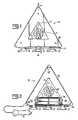
- FIG. 1is a front view of a warning light apparatus, according to a preferred embodiment of the present invention.
- FIG. 2is an interior view of the warning light apparatus of FIG. 1 , according to a preferred embodiment of the present invention.
- FIG. 3is bottom view of the warning light apparatus of FIG. 1 showing the base, according to a preferred embodiment of the present invention.
- FIG. 4is front view of an alternate embodiment of a warning light apparatus, according to a preferred embodiment of the present invention.
- FIG. 5is a detailed, side view of the alternate embodiment of the warning light apparatus of FIG. 4 , according to a preferred embodiment of present invention.
- FIG. 6is an electrical schematic diagram of a warning light apparatus, according to a preferred embodiment of the present invention.
- FIG. 7is a perspective view of a warning light apparatus, according to a preferred alternative embodiment of the present invention.
- FIG. 8is a perspective view of a warning light apparatus, according to a preferred alternative embodiment of the present invention.
- the present inventionis a new, improved flashing warning light apparatus that minimizes these issues.
- the light of the present inventionallows those motorists pausing alongside a highway, or those who are engaged in other roadside activities or emergencies, to alert oncoming traffic of their presence without having to fear that they are depleting their vehicle's battery.
- the warning light's features and advantagesmay prove to be very useful for alerting oncoming traffic of possible dangers posed by drivers or occupants of vehicles, such as the following: (1) occupants of roadside vehicles who are awaiting help following vehicular breakdown or tire changes, for example, who are not using their hazard lights for the fear of battery depletion; (2) unoccupied, unattended, or abandoned roadside vehicles left overnight, or for extended periods of time; (3) recreational vehicles, long haul truckers and/or 18 wheelers parked along the roadside overnight or for an extended period of time; (4) vehicles parked along highways at night, during sporting events, social gatherings, and special events; (5) vehicles involved in highway accidents (that because of their location on or along the roadway may endanger oncoming traffic); (6) vehicles broken down in the direct path of oncoming traffic; (7) all roadside vehicles during bad weather, snow, fog, etc.; (8) maintenance vehicles and crews working along highways; (9) vehicles stopped in inconspicuous places, such as over hills and around curves; and (10) train crossings.
- FIG. 1shows an exterior front view of warning light 10 ; the rear view of warning light 10 is preferably the same as the front view.
- the warning light 10carries arrays of lights 12 such as light emitting diodes (LEDs) or low wattage halogen lamps, in the center of its front and rear faces.
- LEDslight emitting diodes
- halogen lampslow wattage halogen lamps
- Arrays 12are preferably a large enough array, such as, for example, to include at least 20 LEDs.
- Each array 12should be large enough and bright enough to be seen by oncoming traffic from a suitable stopping distance away, preferably at least 400 feet.
- One array 12is visible from the front of warning light 10 and one is visible from the rear of warning light 10 .
- a light sensor 14that detects the headlights of oncoming vehicular traffic.
- One sensor 14faces forward from the front face of warning light 10 and one faces rearward from the rear face of warning light 10 .
- warning light 10has a base 16 with three legs 18 (best seen in FIG. 3 ), each of which has a suction cup 22 or a magnet capable of supporting the weight of warning light 10 when stuck to a clean, smooth or metallic surface.
- a battery box 26dimensioned to hold a suitable number of standard-sized dry cell batteries, solar-celled batteries, or dry-celled batteries charged by solar-celled batteries, that produce the requisite voltage to operate an array for many hours.
- These batteriesmay be any size and number, such as D, C, AA or AAA, or any variation of solar-cells, but preferably, box 26 is dimensioned to house eight AA batteries 28 in series to generate an electrical potential of 12 volts DC.
- the duration of warning lightwill of course vary based on the type of battery, with alkaline or lithium batteries lasting longer than more conventional batteries.
- warning light 10may be operated from the 12 volt car battery through the cigarette lighter when equipped with a cigarette lighter adapter 34 , as shown in FIG. 2 .
- warning light 10will drain current from both sources beginning with batteries 28 and then the car battery.
- warning light 10When connected to the vehicle's cigarette lighter via adapter 34 , or when battery box 26 has a supply of fresh batteries 28 , warning light 10 may operate in one of two modes, depending on the selection of the user.
- the userindicates his or her selection using the positions of a three-way switch 36 .
- Both the front and rear arrays 12operate independently of each other but are powered by the same sources, either batteries 28 in battery box 26 or via the car cigarette lighter adaptor 34 .
- switch 36In a first position, switch 36 is OFF; in either of the other two positions, it is ON.
- One of the ON positionswill result in array 12 flashing intermittently but continuously until either switched to the OFF position or to the other ON position.
- array 12will flash whenever sensor 14 senses oncoming traffic at night.
- Sensoris preferably a light sensor such as a cadmium sulfide photocell, but alternatively, may be a motion sensor, a radar sensor, a sonic sensor, or an infrared sensor.
- the type of sensorwould dictate what was sensed, such as object speed, a hot engine, or a moving object.
- the headlights of oncoming trafficwill be sensed and initiate a series of flashes of sufficient duration, preferably about ten seconds, to alert the drivers in the oncoming vehicle of the existence of potential a roadside hazard until the vehicle passes. Thereafter, array 12 will not flash until the next oncoming vehicle is sensed.
- housing 24 and base 16are made of plastic by injection molding and either colored or covered in a bright color, such as orange or yellow, and most preferably fluorescent colors.
- FIGS. 4 and 5illustrate an alternative embodiment of the present invention for an alternative use.
- FIGS. 4 and 5show a warning light 40 in use attached to an object in order to call a motorist's attention to the object.
- the objectis a traffic sign 42 .
- Other objectscould include highway barriers and road obstructions.
- a country roadmay have an intersection at the end of a short, sharp curve.
- a warning sign of an intersection placed in advance of that intersectionwarns of the intersection ahead but a motorist may miss that sign.
- Having warning light 40 flash when the headlights of the motorist's car strike itwill increase the likelihood that the motorist will see the warning sign and heed it.
- warning light 40cannot be powered by batteries indefinitely, the batteries must be chargeable using electric solar cells 44 during daylight so that it can operate throughout the night from the recharged internal batteries.
- tamper-resistant bolts 46can be used to fasten warning light 40 to the post 48 that holds the traffic sign 42 so that vandals cannot easily remove warning light 40 .
- LED array 50 and sensor 52may be carried only on the front of warning light 40 when it is attached to a traffic sign 42 .
- FIG. 6illustrates one of them. Power is provided by either the 12 Volt DC car battery 60 or a set 62 of eight 1.5-volt dry cell batteries in the warning light housing arranged electrically in series to generate 12 volts.
- Switch 36is used to select from among the first ON position (flashing continuously), the OFF position and the second ON position (flashing for a limited period of time in response to a signal).
- a flash controller 66causes the flashing of two LED arrays 70 , 72 , for the front and back, respectively.
- Two sensors, 76 and 78are connected to LED arrays 70 and 72 , respectively, via a sensor controller 80 to the gates of transistors 84 , 86 , respectively.
- the present devicecan issue an audible signal or, if the oncoming vehicle is suitably equipped, a radio frequency, microwave or digital signal can be transmitted for detection by a receiver in the oncoming vehicle to alert the driver of the oncoming vehicle that he or she is approaching a stopped vehicle.
- a preferred alternative embodiment of the present inventionincludes a first transmitter 100 that is housed by warning light 10 .
- First transmitter 100is capable of transmitting signals, such as radio or microwave, that are detected by first receiver 110 that is housed by a receiver unit 111 , which may be located in the oncoming vehicle and can be clipped to the sun visor by a clip 120 .
- Receiver unit 110can be operated by an on/off switch 140 and contains an audible warning device in the form of a playback module 130 that audibly warns the passengers in the oncoming vehicle when they are approaching the warning light 10 .
- receiver unit 110may include a chime 150 (not shown) for warning oncoming vehicles.
- Receiver unit 110further includes a second transmitter 160 that is capable of transmitting signals that are detected by a second receiver 170 housed by warning light 10 .
- second receiver 170Upon receiving such signal, second receiver 170 activates array 12 .
- Transmitter 100 and receiver unit 110preferably communicate back and forth through built in antennae.
- the audible warningoccurs when the oncoming vehicle is approximately 1000 feet from warning light 10 ; however, other distances are contemplated depending on the distance required to safely and effectively warn oncoming traffic.
- first transmitter 100sends a signal to first receiver 110 , which activates an audible warning within the cabin of an oncoming vehicle.
- second transmitter 160sends a signal to second receiver 170 to activate the array 12 . Therefore, the oncoming car is warned by a combination of audible warning and visible warning.
- This transmitter/receiver systemmay also be employed at train crossings so that an oncoming vehicle can be warned both audibly and visibly by warning light 10 at a train crossing when a train is approaching. While these embodiments can be added to a vehicle after purchase, they are better incorporated into the vehicle during manufacture.
- another improvementcan include the use of a reflector 200 on warning light 10 housing so that oncoming vehicles are not only warned by array 13 , but also by the reflection of the headlights off of reflector 200 .
Landscapes
- Physics & Mathematics (AREA)
- General Physics & Mathematics (AREA)
- Engineering & Computer Science (AREA)
- Mechanical Engineering (AREA)
- Lighting Device Outwards From Vehicle And Optical Signal (AREA)
Abstract
Description
Claims (18)
Priority Applications (1)
| Application Number | Priority Date | Filing Date | Title |
|---|---|---|---|
| US10/449,579US6963275B2 (en) | 2002-05-31 | 2003-05-30 | Portable warning light apparatus |
Applications Claiming Priority (2)
| Application Number | Priority Date | Filing Date | Title |
|---|---|---|---|
| US38450802P | 2002-05-31 | 2002-05-31 | |
| US10/449,579US6963275B2 (en) | 2002-05-31 | 2003-05-30 | Portable warning light apparatus |
Publications (2)
| Publication Number | Publication Date |
|---|---|
| US20030222791A1 US20030222791A1 (en) | 2003-12-04 |
| US6963275B2true US6963275B2 (en) | 2005-11-08 |
Family
ID=29587097
Family Applications (1)
| Application Number | Title | Priority Date | Filing Date |
|---|---|---|---|
| US10/449,579Expired - Fee RelatedUS6963275B2 (en) | 2002-05-31 | 2003-05-30 | Portable warning light apparatus |
Country Status (1)
| Country | Link |
|---|---|
| US (1) | US6963275B2 (en) |
Cited By (37)
| Publication number | Priority date | Publication date | Assignee | Title |
|---|---|---|---|---|
| US20060092652A1 (en)* | 2004-11-03 | 2006-05-04 | Billy Lau | Lighting apparatus |
| US20060232962A1 (en)* | 2005-04-14 | 2006-10-19 | Safe And Sound Safety Corporation | Hazard marker kit |
| US20070014104A1 (en)* | 2005-07-14 | 2007-01-18 | John Browder | Store display for solar lamp |
| US20070121317A1 (en)* | 2005-11-25 | 2007-05-31 | Giant Asia Energy Service Co. | Solar lighting device having color and brightness control mechanism |
| US20070159836A1 (en)* | 2006-01-06 | 2007-07-12 | Bin-Juine Huang | Solar photo-voltaic panel and light structure |
| US20070176784A1 (en)* | 2006-02-01 | 2007-08-02 | Turboflare Usa, Llc | Hazard marker |
| US20070194891A1 (en)* | 2006-02-22 | 2007-08-23 | Wolo Manufacturing Corp | Display assembly with horn configuration for vehicle |
| US20070242451A1 (en)* | 2004-02-13 | 2007-10-18 | Simon Richmond | Light device |
| US20080006199A1 (en)* | 2006-07-10 | 2008-01-10 | Harruna Issifu I | Road safety system and methods of use thereof |
| US20080088477A1 (en)* | 2006-10-13 | 2008-04-17 | Louis Martin | Omnidirectional universal mount hazard marker |
| US20080106891A1 (en)* | 2006-11-02 | 2008-05-08 | Wen-Sung Lee | Intelligent solar electric torch |
| USD573499S1 (en) | 2007-07-31 | 2008-07-22 | Gary Dale King | Help sign |
| US20090009315A1 (en)* | 2007-07-04 | 2009-01-08 | Hsueh-Yen Liu | Foldable warning device |
| US20090078604A1 (en)* | 2004-02-13 | 2009-03-26 | Richmond Simon N | Light Device |
| US20090260562A1 (en)* | 2008-04-17 | 2009-10-22 | Jlt Global Enterprises | Retractable Parking and Safety Cone and Method of Use |
| US20100141467A1 (en)* | 2007-02-07 | 2010-06-10 | Gary John Kirkpatrick | Apparatus for Providing Visual and/or Audible Alert Signals |
| US20100148989A1 (en)* | 2008-12-12 | 2010-06-17 | Hawkins Mark P | Safety or Alert Device |
| US20100177517A1 (en)* | 2009-01-10 | 2010-07-15 | Stephen Foley | Safety flag |
| US20100207788A1 (en)* | 2006-06-06 | 2010-08-19 | Jones Richard D | Flashing beacon |
| US20100277899A1 (en)* | 2009-05-04 | 2010-11-04 | Jason Peak | Utility light with articulating mounting legs adapted with suction cup fasteners |
| US8935988B1 (en) | 2012-06-08 | 2015-01-20 | Jose Praxistelez Perez | Emergency balloon system for roads |
| USD744132S1 (en)* | 2014-04-17 | 2015-11-24 | Brainy Bike Lights Ltd. | Bicycle light |
| US9500347B2 (en) | 2004-02-13 | 2016-11-22 | Simon N. Richmond | Package and light device |
| US9659493B2 (en) | 2006-06-06 | 2017-05-23 | R.D. Jones, Stop Experts, Inc. | Traffic beacon |
| EP3218887A4 (en)* | 2014-11-15 | 2018-07-18 | James R. Selevan | Sequential and coordinated flashing of electronic roadside flares with active energy conservation |
| US20180208107A1 (en)* | 2017-01-19 | 2018-07-26 | Manuela Melton | Intervehicle message center system |
| US10102782B1 (en) | 2017-04-25 | 2018-10-16 | Roman Konshin | Road side vehicle distress sign |
| US10106075B2 (en) | 2017-02-14 | 2018-10-23 | Ford Global Technologies, Llc | Vehicle hazard notification system |
| US10551014B2 (en) | 2017-02-10 | 2020-02-04 | James R. Selevan | Portable electronic flare carrying case and system |
| US10584834B2 (en) | 2017-08-16 | 2020-03-10 | Alivia Williams | Removably mountable lighting module system and method |
| US10660183B2 (en) | 2017-07-06 | 2020-05-19 | James R Selevan | Devices and methods for synchronized signaling of the positions of moving pedestrians or vehicles |
| US10711981B2 (en) | 2004-02-13 | 2020-07-14 | Simon N. Richmond | Package and light device |
| US10922987B2 (en) | 2008-03-15 | 2021-02-16 | James R. Selevan | Sequenced guiding systems for vehicles and pedestrians |
| US11313546B2 (en) | 2014-11-15 | 2022-04-26 | James R. Selevan | Sequential and coordinated flashing of electronic roadside flares with active energy conservation |
| US11725785B2 (en) | 2017-02-10 | 2023-08-15 | James R. Selevan | Portable electronic flare carrying case and system |
| US12277845B2 (en) | 2021-12-29 | 2025-04-15 | Adam Jordan Selevan | Vehicular incursion alert systems and methods |
| US12385196B2 (en) | 2022-02-11 | 2025-08-12 | Daniel Joseph Selevan | Networkable devices for internal illumination of traffic cones and other traffic channelizing devices |
Families Citing this family (9)
| Publication number | Priority date | Publication date | Assignee | Title |
|---|---|---|---|---|
| JP2007527047A (en)* | 2003-06-30 | 2007-09-20 | コーニンクレッカ フィリップス エレクトロニクス エヌ ヴィ | Single LED drive device for traffic lights |
| US20050018444A1 (en)* | 2003-07-23 | 2005-01-27 | Todd Larry R. | Illuminated hazard warning light |
| US20050239581A1 (en)* | 2004-04-23 | 2005-10-27 | Naylor Roger A Sr | Illuminated display |
| US7093953B1 (en)* | 2005-06-03 | 2006-08-22 | Dicke Tool Company | Warning light |
| US7388514B1 (en) | 2005-07-22 | 2008-06-17 | Mcdow Steven E | Emergency light assembly |
| US20070030680A1 (en)* | 2005-08-02 | 2007-02-08 | Wen-Hsin Chao | Warning device having light emitting effect |
| US20070171040A1 (en)* | 2006-01-24 | 2007-07-26 | Shih-Hsiung Li | Vehicle locator beacon |
| US20150251598A1 (en)* | 2014-03-04 | 2015-09-10 | Errol Andrews | Vehicle Hazard Light Strip |
| CN104617642A (en)* | 2015-03-04 | 2015-05-13 | 刘君才 | Portable power source with traffic warning lamp |
Citations (9)
| Publication number | Priority date | Publication date | Assignee | Title |
|---|---|---|---|---|
| US4330706A (en)* | 1979-03-12 | 1982-05-18 | Aimpoint Ab | Photocell controlled power supply circuit for an LED |
| US5005004A (en)* | 1988-10-21 | 1991-04-02 | Udofot Michael P | Light activated vehicle sensor with flashing light and pulsing sound alarm |
| US5175528A (en)* | 1989-10-11 | 1992-12-29 | Grace Technology, Inc. | Double oscillator battery powered flashing superluminescent light emitting diode safety warning light |
| US5914651A (en) | 1997-12-04 | 1999-06-22 | Smalls; Bryan H. | Vehicle safety emergency flasher system |
| US6273597B1 (en)* | 2000-04-08 | 2001-08-14 | William Rolack | Roadside warning sign system |
| US6275149B1 (en)* | 1999-10-14 | 2001-08-14 | Rong-Fang Tung | Illuminant triangular warning arrangement |
| US6422714B1 (en)* | 1999-02-11 | 2002-07-23 | David Hubbell | Illuminated, solar powered, vehicle activated, traffic sign |
| US6707389B2 (en)* | 1999-08-04 | 2004-03-16 | 911Ep, Inc. | LED personal warning light |
| US6798354B2 (en)* | 2000-02-18 | 2004-09-28 | Daimlerchrysler Ag | Device for warning the driver of a motor vehicle of dangers by radio |
- 2003
- 2003-05-30USUS10/449,579patent/US6963275B2/ennot_activeExpired - Fee Related
Patent Citations (9)
| Publication number | Priority date | Publication date | Assignee | Title |
|---|---|---|---|---|
| US4330706A (en)* | 1979-03-12 | 1982-05-18 | Aimpoint Ab | Photocell controlled power supply circuit for an LED |
| US5005004A (en)* | 1988-10-21 | 1991-04-02 | Udofot Michael P | Light activated vehicle sensor with flashing light and pulsing sound alarm |
| US5175528A (en)* | 1989-10-11 | 1992-12-29 | Grace Technology, Inc. | Double oscillator battery powered flashing superluminescent light emitting diode safety warning light |
| US5914651A (en) | 1997-12-04 | 1999-06-22 | Smalls; Bryan H. | Vehicle safety emergency flasher system |
| US6422714B1 (en)* | 1999-02-11 | 2002-07-23 | David Hubbell | Illuminated, solar powered, vehicle activated, traffic sign |
| US6707389B2 (en)* | 1999-08-04 | 2004-03-16 | 911Ep, Inc. | LED personal warning light |
| US6275149B1 (en)* | 1999-10-14 | 2001-08-14 | Rong-Fang Tung | Illuminant triangular warning arrangement |
| US6798354B2 (en)* | 2000-02-18 | 2004-09-28 | Daimlerchrysler Ag | Device for warning the driver of a motor vehicle of dangers by radio |
| US6273597B1 (en)* | 2000-04-08 | 2001-08-14 | William Rolack | Roadside warning sign system |
Cited By (58)
| Publication number | Priority date | Publication date | Assignee | Title |
|---|---|---|---|---|
| US10711981B2 (en) | 2004-02-13 | 2020-07-14 | Simon N. Richmond | Package and light device |
| US20110205730A1 (en)* | 2004-02-13 | 2011-08-25 | Richmond Simon N | Light Device |
| US7967465B2 (en) | 2004-02-13 | 2011-06-28 | Simon Nicholas Richmond | Light device |
| US9500347B2 (en) | 2004-02-13 | 2016-11-22 | Simon N. Richmond | Package and light device |
| US10139083B2 (en) | 2004-02-13 | 2018-11-27 | Simon N. Richmond | Package and light device |
| US20090078604A1 (en)* | 2004-02-13 | 2009-03-26 | Richmond Simon N | Light Device |
| US8256916B2 (en) | 2004-02-13 | 2012-09-04 | Richmond Simon N | Light device |
| US20070242451A1 (en)* | 2004-02-13 | 2007-10-18 | Simon Richmond | Light device |
| US20060092652A1 (en)* | 2004-11-03 | 2006-05-04 | Billy Lau | Lighting apparatus |
| US20060232962A1 (en)* | 2005-04-14 | 2006-10-19 | Safe And Sound Safety Corporation | Hazard marker kit |
| US20070014104A1 (en)* | 2005-07-14 | 2007-01-18 | John Browder | Store display for solar lamp |
| US7497588B2 (en)* | 2005-07-14 | 2009-03-03 | International Development Corporation | Store display for solar lamp |
| US20070121317A1 (en)* | 2005-11-25 | 2007-05-31 | Giant Asia Energy Service Co. | Solar lighting device having color and brightness control mechanism |
| US20070159836A1 (en)* | 2006-01-06 | 2007-07-12 | Bin-Juine Huang | Solar photo-voltaic panel and light structure |
| US20070176784A1 (en)* | 2006-02-01 | 2007-08-02 | Turboflare Usa, Llc | Hazard marker |
| US7394351B2 (en)* | 2006-02-22 | 2008-07-01 | Wolo Manufacturing Corp. | Display assembly with horn configuration for vehicle |
| US20070194891A1 (en)* | 2006-02-22 | 2007-08-23 | Wolo Manufacturing Corp | Display assembly with horn configuration for vehicle |
| US9659493B2 (en) | 2006-06-06 | 2017-05-23 | R.D. Jones, Stop Experts, Inc. | Traffic beacon |
| US9886854B2 (en) | 2006-06-06 | 2018-02-06 | R.D. Jones, Stop Experts, Inc. | Traffic beacon |
| US20100207788A1 (en)* | 2006-06-06 | 2010-08-19 | Jones Richard D | Flashing beacon |
| US8269654B2 (en)* | 2006-06-06 | 2012-09-18 | Jones Richard D | Flashing beacon |
| US8081087B2 (en)* | 2006-06-06 | 2011-12-20 | R. D. Jones, Stop Experts, Incorporated | Flashing beacon |
| US20080006199A1 (en)* | 2006-07-10 | 2008-01-10 | Harruna Issifu I | Road safety system and methods of use thereof |
| US7395776B2 (en) | 2006-07-10 | 2008-07-08 | Issifu I Harruna | Road safety system and methods of use thereof |
| US7623026B2 (en) | 2006-10-13 | 2009-11-24 | TotalFlare, Inc. | Omni directional universal mount hazard marker |
| US20080088477A1 (en)* | 2006-10-13 | 2008-04-17 | Louis Martin | Omnidirectional universal mount hazard marker |
| US20080106891A1 (en)* | 2006-11-02 | 2008-05-08 | Wen-Sung Lee | Intelligent solar electric torch |
| US20100141467A1 (en)* | 2007-02-07 | 2010-06-10 | Gary John Kirkpatrick | Apparatus for Providing Visual and/or Audible Alert Signals |
| US20090009315A1 (en)* | 2007-07-04 | 2009-01-08 | Hsueh-Yen Liu | Foldable warning device |
| USD573499S1 (en) | 2007-07-31 | 2008-07-22 | Gary Dale King | Help sign |
| US11769418B2 (en) | 2008-03-15 | 2023-09-26 | James R. Selevan | Sequenced guiding systems for vehicles and pedestrians |
| US11295625B2 (en) | 2008-03-15 | 2022-04-05 | James R. Selevan | Sequenced guiding systems for vehicles and pedestrians |
| US10922987B2 (en) | 2008-03-15 | 2021-02-16 | James R. Selevan | Sequenced guiding systems for vehicles and pedestrians |
| US20090260562A1 (en)* | 2008-04-17 | 2009-10-22 | Jlt Global Enterprises | Retractable Parking and Safety Cone and Method of Use |
| US20100148989A1 (en)* | 2008-12-12 | 2010-06-17 | Hawkins Mark P | Safety or Alert Device |
| US8007120B2 (en)* | 2009-01-10 | 2011-08-30 | SRS Safety Concepts, LLC | Safety flag |
| US20100177517A1 (en)* | 2009-01-10 | 2010-07-15 | Stephen Foley | Safety flag |
| US20100277899A1 (en)* | 2009-05-04 | 2010-11-04 | Jason Peak | Utility light with articulating mounting legs adapted with suction cup fasteners |
| US8142045B2 (en) | 2009-05-04 | 2012-03-27 | Jason Peak | Utility light with articulating mounting legs adapted with suction cup fasteners |
| US8935988B1 (en) | 2012-06-08 | 2015-01-20 | Jose Praxistelez Perez | Emergency balloon system for roads |
| USD744132S1 (en)* | 2014-04-17 | 2015-11-24 | Brainy Bike Lights Ltd. | Bicycle light |
| US11313546B2 (en) | 2014-11-15 | 2022-04-26 | James R. Selevan | Sequential and coordinated flashing of electronic roadside flares with active energy conservation |
| US11698186B2 (en) | 2014-11-15 | 2023-07-11 | James R. Selevan | Sequential and coordinated flashing of electronic roadside flares with active energy conservation |
| US12203637B2 (en) | 2014-11-15 | 2025-01-21 | James R. Selevan | Sequential and coordinated flashing of electronic roadside flares with active energy conservation |
| EP3218887A4 (en)* | 2014-11-15 | 2018-07-18 | James R. Selevan | Sequential and coordinated flashing of electronic roadside flares with active energy conservation |
| US10443828B2 (en) | 2014-11-15 | 2019-10-15 | James R. Selevan | Sequential and coordinated flashing of electronic roadside flares with active energy conservation |
| US20180208107A1 (en)* | 2017-01-19 | 2018-07-26 | Manuela Melton | Intervehicle message center system |
| US11162650B2 (en) | 2017-02-10 | 2021-11-02 | James R. Selevan | Portable electronic flare carrying case and system |
| US10551014B2 (en) | 2017-02-10 | 2020-02-04 | James R. Selevan | Portable electronic flare carrying case and system |
| US11725785B2 (en) | 2017-02-10 | 2023-08-15 | James R. Selevan | Portable electronic flare carrying case and system |
| US10106075B2 (en) | 2017-02-14 | 2018-10-23 | Ford Global Technologies, Llc | Vehicle hazard notification system |
| US10102782B1 (en) | 2017-04-25 | 2018-10-16 | Roman Konshin | Road side vehicle distress sign |
| US11013091B2 (en) | 2017-07-06 | 2021-05-18 | James R Selevan | Devices and methods for synchronized signaling of the positions of moving pedestrians or vehicles |
| US11706861B2 (en) | 2017-07-06 | 2023-07-18 | James R. Selevan | Devices and methods for synchronized signaling of the positions of moving pedestrians or vehicles |
| US10660183B2 (en) | 2017-07-06 | 2020-05-19 | James R Selevan | Devices and methods for synchronized signaling of the positions of moving pedestrians or vehicles |
| US10584834B2 (en) | 2017-08-16 | 2020-03-10 | Alivia Williams | Removably mountable lighting module system and method |
| US12277845B2 (en) | 2021-12-29 | 2025-04-15 | Adam Jordan Selevan | Vehicular incursion alert systems and methods |
| US12385196B2 (en) | 2022-02-11 | 2025-08-12 | Daniel Joseph Selevan | Networkable devices for internal illumination of traffic cones and other traffic channelizing devices |
Also Published As
| Publication number | Publication date |
|---|---|
| US20030222791A1 (en) | 2003-12-04 |
Similar Documents
| Publication | Publication Date | Title |
|---|---|---|
| US6963275B2 (en) | Portable warning light apparatus | |
| CA2239849C (en) | Method and apparatus for warning drivers as to the presence of a school bus in the process of loading or unloading a passenger | |
| KR0156556B1 (en) | Signal means | |
| US5276424A (en) | Attention getting sign | |
| US7746247B2 (en) | Wearable, attachable, or hand-held, super-bright, led based, textual, safety alert sign and portable emergency/work light | |
| AU2013101353A4 (en) | Improvements to Pedestrian Crossings | |
| US20040183694A1 (en) | Light emitting traffic sign having vehicle sensing capabilites | |
| EP2636560A1 (en) | Headlight control device | |
| US20050104747A1 (en) | Multi-purpose wireless communication device | |
| US10449892B2 (en) | Signal light | |
| US20220026039A1 (en) | Straight-Ahead Vehicle Signal | |
| US5914651A (en) | Vehicle safety emergency flasher system | |
| US6939021B2 (en) | Triangular light assembly with flashing and non-flashing lights | |
| US20080291003A1 (en) | System and method for providing emergency warnings for a rollover vehicle | |
| JP3832955B2 (en) | Traffic safety system | |
| US6816086B1 (en) | Driveway signaling device | |
| US20160009219A1 (en) | Baby stroller lighting system | |
| KR20120059158A (en) | Road stud | |
| WO2003102892A1 (en) | Portable warning light apparatus | |
| WO2006038853A1 (en) | A system for indicating presence of a person im a road area | |
| US20230034234A1 (en) | Crosswalk Light Device | |
| CN218147943U (en) | Construction early warning system | |
| US20240331543A1 (en) | Pedestrian crosswalk alert system | |
| JP3078929U (en) | Luminous mascot | |
| EP3002882A1 (en) | Signal emitter-receiver device for warning about highway incidents |
Legal Events
| Date | Code | Title | Description |
|---|---|---|---|
| AS | Assignment | Owner name:NU-TECH INNOVATIVE PRODUCTS, LLC, SOUTH CAROLINA Free format text:ASSIGNMENT OF ASSIGNORS INTEREST;ASSIGNOR:SMALLS, BRYAN H.;REEL/FRAME:014153/0103 Effective date:20030530 | |
| REFU | Refund | Free format text:REFUND - SURCHARGE FOR LATE PAYMENT, SMALL ENTITY (ORIGINAL EVENT CODE: R2554); ENTITY STATUS OF PATENT OWNER: MICROENTITY Free format text:REFUND - SURCHARGE, PETITION TO ACCEPT PYMT AFTER EXP, UNINTENTIONAL (ORIGINAL EVENT CODE: R2551); ENTITY STATUS OF PATENT OWNER: MICROENTITY | |
| REMI | Maintenance fee reminder mailed | ||
| FPAY | Fee payment | Year of fee payment:4 | |
| REIN | Reinstatement after maintenance fee payment confirmed | ||
| FEPP | Fee payment procedure | Free format text:PETITION RELATED TO MAINTENANCE FEES FILED (ORIGINAL EVENT CODE: PMFP); ENTITY STATUS OF PATENT OWNER: MICROENTITY | |
| FP | Lapsed due to failure to pay maintenance fee | Effective date:20091108 | |
| SULP | Surcharge for late payment | ||
| FEPP | Fee payment procedure | Free format text:PETITION RELATED TO MAINTENANCE FEES GRANTED (ORIGINAL EVENT CODE: PMFG); ENTITY STATUS OF PATENT OWNER: MICROENTITY | |
| PRDP | Patent reinstated due to the acceptance of a late maintenance fee | Effective date:20110118 | |
| FEPP | Fee payment procedure | Free format text:PATENT HOLDER CLAIMS MICRO ENTITY STATUS, ENTITY STATUS SET TO MICRO (ORIGINAL EVENT CODE: STOM); ENTITY STATUS OF PATENT OWNER: MICROENTITY | |
| REMI | Maintenance fee reminder mailed | ||
| FPAY | Fee payment | Year of fee payment:8 | |
| SULP | Surcharge for late payment | ||
| REMI | Maintenance fee reminder mailed | ||
| LAPS | Lapse for failure to pay maintenance fees | Free format text:PATENT EXPIRED FOR FAILURE TO PAY MAINTENANCE FEES (ORIGINAL EVENT CODE: EXP.) | |
| STCH | Information on status: patent discontinuation | Free format text:PATENT EXPIRED DUE TO NONPAYMENT OF MAINTENANCE FEES UNDER 37 CFR 1.362 | |
| FP | Lapsed due to failure to pay maintenance fee | Effective date:20171108 |