US6962459B2 - Crash attenuator with cable and cylinder arrangement for decelerating vehicles - Google Patents
Crash attenuator with cable and cylinder arrangement for decelerating vehiclesDownload PDFInfo
- Publication number
- US6962459B2 US6962459B2US10/638,543US63854303AUS6962459B2US 6962459 B2US6962459 B2US 6962459B2US 63854303 AUS63854303 AUS 63854303AUS 6962459 B2US6962459 B2US 6962459B2
- Authority
- US
- United States
- Prior art keywords
- crash attenuator
- cylinder
- cable
- vehicle
- recited
- Prior art date
- Legal status (The legal status is an assumption and is not a legal conclusion. Google has not performed a legal analysis and makes no representation as to the accuracy of the status listed.)
- Expired - Lifetime
Links
Images


Classifications
- E—FIXED CONSTRUCTIONS
- E01—CONSTRUCTION OF ROADS, RAILWAYS, OR BRIDGES
- E01F—ADDITIONAL WORK, SUCH AS EQUIPPING ROADS OR THE CONSTRUCTION OF PLATFORMS, HELICOPTER LANDING STAGES, SIGNS, SNOW FENCES, OR THE LIKE
- E01F15/00—Safety arrangements for slowing, redirecting or stopping errant vehicles, e.g. guard posts or bollards; Arrangements for reducing damage to roadside structures due to vehicular impact
- E01F15/14—Safety arrangements for slowing, redirecting or stopping errant vehicles, e.g. guard posts or bollards; Arrangements for reducing damage to roadside structures due to vehicular impact specially adapted for local protection, e.g. for bridge piers, for traffic islands
- E01F15/145—Means for vehicle stopping using impact energy absorbers
- E01F15/146—Means for vehicle stopping using impact energy absorbers fixed arrangements
- E—FIXED CONSTRUCTIONS
- E01—CONSTRUCTION OF ROADS, RAILWAYS, OR BRIDGES
- E01F—ADDITIONAL WORK, SUCH AS EQUIPPING ROADS OR THE CONSTRUCTION OF PLATFORMS, HELICOPTER LANDING STAGES, SIGNS, SNOW FENCES, OR THE LIKE
- E01F15/00—Safety arrangements for slowing, redirecting or stopping errant vehicles, e.g. guard posts or bollards; Arrangements for reducing damage to roadside structures due to vehicular impact
Definitions
- the present inventionrelates to vehicle crash attenuators, and, in particular, to a crash attenuator for controlling the deceleration of crashing vehicles using a cable and cylinder braking arrangement.
- NCHRP Report 350specifies criteria for evaluating the safety performance of various highway devices, such as crash attenuators. Included in NCHRP Report 350 are recommendations for run-down deceleration rates for vehicles to be used in designing crash attenuators that meet NCHRP Report 350's test levels 2, 3 and 4.
- crash attenuatorsthat are deployed today along roadways to redirect or stop vehicles that have left the roadway use various structural arrangements in which the barrier compresses and/or collapses in response to the vehicle impacting the barrier. Some of these crash attenuators also include supplemental braking systems that produce a constant retarding force to slow down crashing vehicles, despite variations in the mass and/or velocity of the vehicle impacting the barrier.
- NCHRP Report 350 for crash testingrequire a maximum vehicle occupant impact speed which is the speed of the occupant striking the interior surface of the vehicle, of 12 meters/second, with a preferred speed of 9 meters/second.
- constant braking force crash attenuatorswill stop a smaller mass vehicle in a distance of around 8 feet. This is because most constant braking force crash attenuators need to exert an increased braking force that will allow larger mass vehicles, such as pickup trucks, to be stopped in a distance of around 17 feet.
- the present inventionis an improved crash attenuator that uses a cable and cylinder braking arrangement to control the rate at which a vehicle impacting the crash attenuator is decelerated to a safe stop.
- the crash attenuator of the present inventionuses a cable and cylinder arrangement that exerts a resistive force that varies over distance to control a crashing vehicle's run-down deceleration and occupant impact speed in accordance with the requirements of NCHRP Report 350.
- the crash attenuator of the present inventionprovides a ride-down travel distance for smaller mass vehicles in which such vehicles, during a high speed impact, are able to travel 10 feet or more before completely stopping.
- the crash attenuator of the present inventionalso includes an elongated guardrail-like structure comprised of a front impact section and a plurality of trailing mobile sections with overlapping side panel sections that telescope down as the crash attenuator is compressed in response to being struck by a vehicle.
- the front impact sectionis rotatably mounted on at least one guiderail attached to the ground, while the mobile sections are slidably mounted on the at least one guiderail. It should be noted, however, that two or more guiderails are preferably used with the crash attenuator of the present invention.
- the cable and cylinder arrangementincludes preferably a steel wire rope cable that is attached to a sled that is part of the attenuator's front impact section by means of an open spelter socket attached to the sled. From the open spelter socket, the cable is pulled through an open backed tube that is affixed to the front base of the crash attenuator.
- a shock-arresting hydraulic or pneumatic cylinderwith a first stack of static sheaves positioned near the back end of the cylinder and a second stack of static sheaves on the end of the cylinder's protruding piston rod.
- All of the sheavesare pinned and rotationally stationary during impact of the crash attenuator by a vehicle.
- the cableis looped several times around the static sheaves located at the rear of the cylinder and at the end of the cylinder's piston rod. Thereafter, the cable is terminated to a threaded adjustable eyebolt that is attached to a plate welded to the side of one of the base rails.
- the front sectionWhen a crashing vehicle impacts the front section of the crash attenuator, the front section is caused to translate backwards on the guiderails towards the multiple mobile sections located behind the front section. As the front section translates backwards, the rear-most portion of a sled acting as its support frame comes into contact with the support frame supporting the panels of the mobile section just behind the front section. This mobile section's support frame, in turn, comes into contact with the support frame supporting the panels of the next mobile section, and so on.
- the cable attached to the sledis caused to frictionally slide around the sheaves and compress or extend the cylinder's piston rod into or out of the cylinder.
- the sheaves located at the end of the piston rodare also attached to a movable plate so that the sheaves move longitudinally as the cylinder's piston rod is compressed into or extended out of the cylinder by the cable as it slides around the sheaves in response to the front section of the crash attenuator being impacted by a vehicle. This results in a restraining force being exerted on the sled to control its backward movement.
- the restraining force exerted by the cable on the sledis controlled by the cylinder, which is metered using internal orifices to give a vehicle impacting the attenuator a controlled ride-down based on the vehicle's kinetic energy.
- a minimum restraining forceis applied to the front section to decelerate the crashing vehicle until the point of occupant impact with the interior surface of the vehicle, after which an increased resistance, but steady deceleration force, is maintained.
- the present inventionuses a cable and cylinder arrangement with a varying restraining force to control the rate at which a crashing vehicle is decelerated to safely stop the vehicle. Accelerating the mass of the frames during collision also contributes to the stopping force. Therefore, the total stopping force is a combination of friction, the resistance exerted by the shock arresting cylinder and the acceleration of structural masses in response to the velocity of the colliding vehicle upon impact and crush factors in the body and frame of the vehicle.
- the crash attenuator of the present inventionalso includes a variety of transition arrangements to provide a smooth continuation from the crash attenuator to a fixed barrier of varying shape and design.
- the structure of the transition unitvaries according to the type of fixed barrier that the crash attenuator is connected to.
- the cable and cylinder arrangement used in the crash attenuator of the present inventioncan be used with or in other structural arrangements that are designed to bear impacts by vehicles and other moving objects.
- the alternative embodiments of the cable and cylinder arrangement with such alternative structural arrangementswould include the cable, the cylinder and sheaves used in the cable and cylinder arrangement of the crash attenuator of the present invention.
- FIG. 1is a side elevational view of the crash attenuator of the present invention in its fully-extended position.
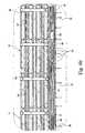
- FIG. 2is a plan view of the crash attenuator of the present invention in its fully-extended position.
- FIG. 3 ais an enlarged partial side elevational view of the front section of the crash attenuator of the present invention.
- FIG. 3 bis an enlarged partial plan view of the front section of the crash attenuator of the present invention.
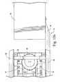
- FIG. 4 ais an enlarged cross-sectional, front elevational view, taken along line 4 a — 4 a of FIG. 2 , of the mobile sheaves used with the crash attenuator of the present invention.
- FIG. 4 bis an enlarged cross-sectional front elevational view, taken along line 4 b — 4 b of FIG. 2 , of the stationary sheaves used with the crash attenuator of the present invention.
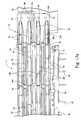
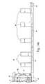
- FIG. 5is a cross-sectional side elevational view of the crash attenuator shown in FIG. 1 .
- FIG. 6 ais an enlarged cross-sectional side elevational view of the front section of the crash attenuator shown in FIG. 5 . (spelter socket pin not shown)
- FIG. 6 bis an enlarged cross-sectional side elevational view of several rear sections of the crash attenuator shown in FIG. 5 .
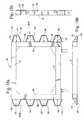
- FIG. 7is a cross-sectional front elevational view of the guardrail structure when completely collapsed after impact.
- FIG. 8is a side elevational perspective view of the crash attenuator in its rest position just prior to impact by a vehicle.
- FIG. 9is a side elevational perspective view of the crash attenuator in which the front section of the attenuator has moved backward and impacted the support frame for the first mobile section of the guardrail structure immediately behind the front section.
- FIG. 10is a side elevational perspective view of the crash attenuator in which the front section and the first and second mobile sections of the attenuator have moved backwards after vehicle impact so as to engage the support structure of the third mobile section of the guardrail structure.
- FIG. 11 ais a side elevational view of a first embodiment of a transition section for connecting the crash attenuator to a thrie-beam guardrail.
- FIG. 11 bis a plan view of the first transition section for connecting the crash attenuator to the thrie-beam guardrail.
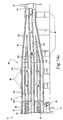
- FIG. 12 ais a side elevational view of a second embodiment of the transition section for connecting the crash attenuator to a jersey barrier.
- FIG. 12 bis a plan view of the second transition section for connecting the crash attenuator to the jersey barrier.
- FIG. 12 cis an end elevational view of a second embodiment of the transition section for connecting the crash attenuator to a jersey barrier.
- FIG. 13 ais a side elevational view showing a third embodiment of the transition section for connecting the crash attenuator to a concrete block.
- FIG. 13 bis a plan view of the third transition section for connecting the crash attenuator to the concrete block.
- FIG. 14 ais a side elevational view showing a fourth embodiment of the transition section for connecting the crash attenuator to a W-beam guardrail.
- FIG. 14 bis a plan view of the fourth transition section for connecting the crash attenuator to the W-beam guardrail.
- FIG. 15is a plan view of the corrugated side panel used with the front section and mobile sections of the crash attenuator of the present invention, the front section panel being a longer version of the mobile section panels.
- FIGS. 16 a - 16 care cross sectional elevational views showing the profiles of several embodiments of the corrugated side panel used with the crash attenuator of the present invention.
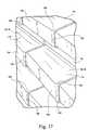
- FIG. 17is a partial side perspective view showing portions of several side panels used with the crash attenuator of the present invention.
- FIGS. 18 a - 18 care front, top and side views, respectively, of a support frame for the corrugated side panels showing different views of brackets and gussets used to further support the side panels.
- the present inventionis a vehicle crash attenuator that uses a cable and cylinder arrangement and collapsing structure to safely decelerate a vehicle impacting the attenuator.
- FIG. 1is a side elevational view of the preferred embodiment of the crash attenuator 10 of the present invention in its fully extended position.
- FIG. 2is a plan view of the crash attenuator 10 of the present invention, again in its fully extended position.
- crash attenuator 10is an elongated guardrail-type structure including a front section 12 and a plurality of mobile sections 14 positioned behind front section 12 . As shown in FIGS. 1 and 2 , front section 12 and mobile sections 14 are positioned longitudinally with respect to one another. Crash attenuator 10 is typically positioned alongside a roadway 11 and oriented with respect to the flow of traffic in roadway 11 shown by arrow 13 in FIG. 2 .
- a corrugated panel 16which preferably has a trapezoidal-like profile.
- Supporting these panels 16is a rectangular-shaped frame or sled 18 that is constructed from four vertical frame members 20 , which, in turn, are joined by four laterally extending substantially parallel cross-frame members 22 and four longitudinally extending substantially parallel cross-frame members 23 for structural rigidity.
- FIG. 1As shown in FIGS. 1 , 2 , 3 a , and 3 b , mounted on each of front section 12 's two sides is a corrugated panel 16 which preferably has a trapezoidal-like profile.
- Supporting these panels 16is a rectangular-shaped frame or sled 18 that is constructed from four vertical frame members 20 , which, in turn, are joined by four laterally extending substantially parallel cross-frame members 22 and four longitudinally extending substantially parallel cross-frame members 23 for structural rigidity.
- front section 12also includes a diagonal-support member 21 extending horizontally and diagonally from the front right of sled 18 to the rear left of sled 18 so as to form a lattice-like structure to resist twisting of sled 18 upon angled frontal hits.
- vertical frame members 20 , cross-frame members 22 , cross-frame members 23 and diagonal-support member 21are all constructed from mild steel tubing and are welded together.
- each of panels 16includes two substantially horizontal slits 24 that extend a partial distance along the length of panel 16 and is mounted on one side of vertical frame members 20 by two bolts 19 . For front side panel 16 , there are two additional mounting bolts 19 holding the front of panel 16 .
- each of the mobile sections 14is constructed with a rectangular-shaped frame 26 that also includes a pair of vertical frame members 20 joined, again, together by a pair of cross-frame members 22 .
- members 20 and 22 forming frames 26are also constructed from mild steel tubing and welded together.
- Mounted on each side of each of the vertical frame members 20 of mobile sections 14is a corrugated side panel 28 that is somewhat shorter in length than each of side panels 16 , but that also have a trapezoidal-like profile like side panels 16 .
- FIGS. 1 and 2show that each frame 26 supports a pair of panels 28 , one on each side of frame 26 .
- panels 28are also made from galvanized steel.
- Each of panels 28also includes two substantially horizontal slits 24 that extend a partial distance along the length of panel 28 and is mounted on one side of vertical frame members 20 by two keeper bolts 30 , which protrude through horizontal slits 24 of preceding and partially overlapping panel 16 .
- overlapping panels 16 and 28act as deflection plates to redirect a vehicle upon laterally striking the crash attenuator 10 .
- Front section 12 and mobile sections 14are not rigidly joined to one another, but interact with one another in a sliding arrangement, as best seen in FIGS. 8-10 .
- each of corrugated panels 28is joined to a vertical support member 20 of a corresponding support frame 26 by a pair of side-keeper bolts 30 that extend through a pair of holes (not shown) in panels 28 .
- the first pairs of side-keeper bolts 30 holding panels 28 onto the first support frame 26 behind front section 12protrude through slits 24 in panels 16 supported by sled 18 .
- the subsequent pairs of side-keeper bolts 30each also protrude through the slits 24 that extend horizontally along a panel 28 that is longitudinally ahead of that pair of bolts.
- each of corrugated panels 28has a fixed end 27 joined by a pair of side-keeper bolts 30 to a support frame 26 and a floating end 29 through which a second pair of side-keeper bolts 30 protrudes through the slits 24 extending along the panel, such that the floating end 29 of the panel overlaps the fixed end 27 of the corrugated panel 28 longitudinally behind it and adjacent to it.
- each of side-keeper bolts 30preferably includes a rectangular-shaped head 30 a having a width that is large enough to prevent the corresponding slit 24 through which the bolt 30 extends from moving sideways away from its supporting frame 26 .
- sled 18 of front section 12is rotatably mounted on preferably two substantially parallel guiderails 32 and 34 , while each of support frames 26 of mobile sections 14 are all slidably mounted on guiderails 32 and 34 .
- Guiderails 32 and 34are steel C-channel rails that are anchored to the ground 35 by a plurality of anchors 36 .
- Anchors 36are typically bolts that protrude through guiderail support plates 36 A into a suitable base material, such as concrete 37 or asphalt (not shown), that has been buried in the ground 35 .
- the base materialis used as a drill template for anchors 36 .
- the base materialis in the form of a pad extending at least the length of crash attenuator 10 .
- this padis a 28 MPa or 4000 PSI min. steel reinforced concrete that is six inches thick and flush with the ground.
- Mounting holes in concrete 37receive anchors 36 protruding through guiderail support plates 36 A.
- Front section 12is rotatably mounted on guiderails 32 and 34 by a plurality (preferably four) of roller assemblies 39 on which sled 18 of front section 12 is mounted to prevent sled 18 from hanging up as it slides along guiderails 32 and 34 .
- roller assemblies 39includes a wheel 39 a that engages and rides on an inside channel 43 of C-channel rails 32 and 34 .
- Support frames 26are attached to guiderails 32 and 34 by a bracket 38 that is a side guide that engages the upper portion of guiderails 32 and 34 .
- Each of support section frames 26includes a pair of side guides 38 .
- Each side guide 38 supporting mobile sections 14is bolted or welded to one side of the vertical support members 20 used to form frames 26 .
- the side guides 38track guiderails 32 and 34 back as the crash attenuator telescopes down in response to a frontal hit by a crashing vehicle 50 .
- roller assemblies 39 and side guides 38 engaging guiderails 32 and 34they serve the functions of giving attenuator 10 longitudinal strength, deflection strength, and impact stability by preventing crash attenuator 10 from buckling up or sideways upon frontal or side impacts, thereby allowing a crashing vehicle to be redirected during a side impact.
- each of support frames 26would include a pair of side guides 38 that would slidably track guiderail 32 / 34 as crash attenuator 10 telescopes down in response to a frontal hit by a crashing vehicle 50 .
- skid legsmounted on the outside of front section 12 and support frames 26 for balancing purposes. Located on the bottom of the skid legs would be a skid that slides along the base material, such as concrete 37 , buried in ground 35 .
- FIGS. 8 to 10when a crashing vehicle 50 hits the front surface of crash attenuator 10 , it strikes front section 12 containing sled 18 . Front section 12 and sled 18 are then caused to translate backwards on guiderails 32 and 34 towards mobile sections 14 behind front section 12 . As front section 12 translates backwards, the rear-most part of sled 18 crashes into the support frame 26 ′ of the first mobile section 14 ′ just behind front section 12 . This first section's support frame 26 ′, in turn, crashes into the support frame 26 ′′ of the next mobile section 14 ′′, and so on.
- a cable 41is attached to front sled 18 by an open spelter socket 40 attached to sled 18 .
- cable 41is a 1.125′′ diameter wire rope cable formed from galvanized steel.
- cable 41could be formed from metals other than galvanized steel, or from other non-metallic materials, such as nylon, provided that cable 41 , when made from such other materials has sufficient tensile strength, which is preferably at least 27,500 lbs. Cable 41 could also be a chain rather than a rope design, provided that it has such tensile strength.
- FIG. 4 bshows the circular steel guide ring bushings 31 attached to guiderail 32 by gusset 33 that help protect cable 41 as it travels back to cylinder 44 through a plurality of gussets 33 (see, e.g., FIG. 2 ) extending between guiderails 32 and 34 .
- cable 41first runs to the bottom sheave of multiple sheaves 45 positioned at the back of cylinder 44 . Cable 41 then runs to the bottom sheave of multiple sheaves 46 positioned at the front end of cylinder piston rod 47 .
- Multiple sheaves 46are attached to a movable plate 48 , which slides longitudinally backwards as cylinder piston rod 47 is compressed into cylinder 44 .
- cable 41is looped a total of three times around multiple sheaves 45 and 46 , after which cable 41 is terminated in a threaded adjustable eye bolt 49 attached to a plate 59 that is welded to the inside of C-channel 32 (see, e.g., FIG. 6 b ). Cable 41 is terminated to adjustable eyebolt 49 using multiple wire rope clips 57 shown in FIGS. 5 and 6 b .
- Multiple sheaves 45 and 46are each pinned by a pair of pins 51 (see, e.g., FIG.
- front section 12When front section 12 is hit by a vehicle 50 , it is pushed back by vehicle 50 until sled 18 contacts the support frame 26 ′ of the first mobile section 14 ′ behind front section 12 .
- cable 41 in combination with cylinder 44exerts a force that resists the movement of section 12 and sled 18 backwards.
- the resistive force exerted by cable 41is controlled by shock-arresting cylinder 44 .
- Cylinder 44is metered with internal orifices (not shown) running longitudinally within cylinder 44 .
- the orifices in cylinder 44allow a hydraulic or pneumatic fluid from a first, inner compartment (also not shown) within piston 44 escape to a second, outer jacket compartment (also not shown) of cylinder 44 .
- the orificescontrol the amount of fluid that can move from the inner compartment to the outer compartment at any given time.
- piston rod 47moves past various orifices within cylinder 44 , those orifices become unavailable for fluid movement, resulting in an energy-dependent resistance to a compressing force being exerted on piston rod 47 of cylinder 44 by cable 41 as it is pulled around the pair of multiple sheaves 45 and 46 in response to being pulled backwards by sled 18 of front section 12 .
- the size and spacing of the orifices within cylinder 44are preferably designed to steadily decrease the amount of fluid that can move from the inner compartment to the outer compartment of cylinder 44 at any given time in coordination with the decrease in velocity of impacting vehicle 50 over a predefined distance so that vehicle 50 experiences a substantially constant rate of deceleration to thereby provide a steady ride-down in velocity for vehicle 50 .
- this arrangementincreases or decreases resistance, depending on whether the impacting vehicle has a higher or lower velocity, respectively, than cylinder 44 is designed to readily handle, allowing extended ridedown distances for both slower velocity vehicles (due to decreased resistance) and higher velocity vehicles (due to increased resistance).
- Cylinder 44 's control of the resisting force exerted on sled 18 by cable 41results in attenuator 10 providing a controlled ride-down of any vehicle 50 impacting attenuator 10 that is based on the kinetic energy of vehicle 50 as it impacts attenuator 10 .
- vehicle 50first impacts sled 18 of attenuator 10 , its initial velocity is very high, and, thus, initially, sled 18 is accelerated by vehicle 50 to a very high velocity.
- cable 41is pulled backwards and around sheaves 45 and 46 very rapidly, causing cylinder 44 to be compressed very rapidly.
- fluid compartments of cylinder 44can be of alternative designs, wherein the first and second compartments, which are inner and outer compartments in the embodiment described above, are side by side or top and bottom, by way of alternative examples.
- cylinder 44 and piston rod 47can be reversed, wherein piston rod 47 's rest position is to be initially within cylinder 44 , rather than initially extended from cylinder 44 .
- cable 41would be terminated at the end of piston rod 47 and both the first and second multiplicity of sheaves 45 and 46 would be stationary.
- Cylinder 44would again include orifices to control the amount of fluid being transferred from a first chamber to a second chamber as piston rod 47 extends out of cylinder 44 .
- multiple cylinders 44 and/or multiple cables 41could be used in the operation of crash attenuator 10 of the present invention.
- the multiple cylinders 44could be positioned in tandem, with corresponding multiple, compressible piston rods 47 being attached to movable plate 48 on which movable multiple sheaves 46 are mounted through an appropriate bracket (not shown).
- at least one cable 41would still be looped around multiple sheaves 45 and 46 , after which it would be terminated in eye bolt 49 attached to plate 59 .
- one or more cables 41could be terminated at the end of multiple, extendable piston rods 47 after being looped around multiple sheaves 45 and 46 .
- multiple cylinders 44could be positioned in tandem. A single cable 41 would be attached to extendable piston rods 47 through an appropriate bracket (not shown).
- the crash attenuator 10 of the present inventionis a vehicle-energy-dependent system which allows vehicles of smaller masses to be decelerated in a longer ride-down than fixed force systems that are designed to handle smaller and larger mass vehicles with the same fixed stopping force.
- the friction from cable 41 being pulled around open backed tube 42 and multiple sheaves 45 and 46dissipates a significant amount of the kinetic energy of a vehicle striking crash attenuator 10 .
- the dissipation of a vehicle's kinetic energy by such frictionallows the use of a smaller bore cylinder 44 .
- the multiple loops of cable 41 around sheaves 45 and 46provides a 6 to 1 mechanical advantage ratio, which allows a 34.5′′ stroke for piston rod 47 of cylinder 44 with a 207′′ vehicle travel distance.
- cable 41is formed from a material that produces less friction when cable 41 is pulled around open backed tube 42 and multiple sheaves 45 and 46 a smaller amount of the kinetic energy of a vehicle striking crash attenuator 10 will be dissipated from friction.
- the dissipation of a smaller amount of a vehicle's kinetic energy by such lesser amount of frictionwill require the use of a cylinder 44 with a larger bore and/or orifices with having a larger size that are preferably designed to further decrease the amount of hydraulic fluid that can move from the inner compartment to the outer compartment of cylinder 44 at any given time.
- a premium hydraulic fluid in cylinder 44which has fire resistance properties and a very high viscosity index to allow minimal viscosity changes over a wide ambient mean temperature range.
- the hydraulic fluid used in the present inventionis a fire-resistant fluid, such as Shell IRUS-D fluid with a viscosity index of 210. It should be noted, however, that the present invention is not limited to the use of this particular type of fluid.
- the resistive force exerted by the cable and cylinder arrangement used with the crash attenuator 10 of the present inventionmaintains the deceleration of an impacting vehicle 50 at a predetermined rate of deceleration, i.e., preferably 10 millisecond averages of less than 15 g's, but not to exceed the maximum 20 g's specified by NCHRP Report 350.
- the same cable and cylinder arrangementis used for vehicle velocities of 100 kmh, which is in the NCHRP Level 3 category, as is used for vehicle velocities of 70 kmh (NCHRP Level 2 category unit), or with higher velocities in accordance with NCHRP Level 4 category.
- Level 2 units of the crash attenuatorwould typically be shorter than Level 3 units, since the length needed to stop a slower moving vehicle of a given mass upon impact is shorter than the same vehicle moving at a higher velocity upon impact.
- an attenuator designed for Level 4would be longer since the length needed to stop a faster moving vehicle of the same mass is longer.
- the crash attenuator of the present inventionit is the velocity of a vehicle impacting the attenuator, not simply the mass of the vehicle, that determines the stopping distance of the vehicle to thereby meet the g force exerted on the vehicle during the vehicle ride-down as specified in NCHRP Report 350.
- the number of mobile sections and support frames that a crash attenuatorcould change, depending on the NCHRP Report 350 category level of the attenuator.
- front section 12When a vehicle 50 collides with front section 12 , which is initially at rest, front section 12 is accelerated by vehicle 50 as the cable and cylinder arrangement of the present invention resists the backwards translation of section 12 . Acceleration of front section 12 and sled 18 reduces a predetermined amount of energy resulting from vehicle 50 impacting the front end of crash attenuator 10 .
- an unsecured occupant in a colliding vehiclemust, after travel of 0.6 meters (1.968 ft.) relative to the vehicle reach a preferred velocity of preferably 9 meters per second (29.52 ft. per sec.) or less relative to the vehicle, and not exceeding 12 meters per second.
- This design specificationis achieved in the present invention by designing the mass of front section 12 to achieve this occupant velocity for a crashing vehicle having a minimum weight of 820 kg. and a maximum weight of 2000 Kg., and by providing a reduced initial resistive force exerted by the cable and cylinder arrangement of the present invention that is based on the kinetic energy of a vehicle as it impacts the crash attenuator 10 .
- a reduced initial resistive force exerted by the cable and cylinder arrangement of the present inventionthat is based on the kinetic energy of a vehicle as it impacts the crash attenuator 10 .
- FIGS. 8-10when a crashing vehicle 50 hits the front surface 52 of crash attenuator 10 's front section 12 , that section is caused to translate backwards on guiderails 32 and 34 towards the mobile sections 14 behind front section 12 .
- the rear part 54 of front section 12 's support sled 18crashes into the support frame 26 ′ of the mobile section 14 ′ just behind front section 12 .
- the corrugated panels 16 supported by sled 18also translate backwards with front section 12 and slide over the corrugated panels 28 ′ supported by support frame 26 ′ of mobile section 14 ′.
- front section 12 and mobile section 14 ′continue to translate backwards, and support frame 26 ′ of mobile section 14 ′ then crashes into the support frame 26 ′′ of the next mobile section 14 ′′.
- the continued forward travel of crashing vehicle 50causes front section 12 and mobile sections 14 ′ and 14 ′′ to continue translating backwards, whereupon support frame 26 ′′ of mobile section 14 ′′ crashes into the support frame 26 ′′′ of the next mobile section 14 ′′′, and so on until vehicle 50 stops and/or front section 12 and mobile sections 14 are fully stacked onto one another.
- corrugated panels 28 ′ supported by frame 26 ′also translate backwards with mobile section 14 ′ and slides over the corrugated panels 28 ′′ supported by support frame 26 ′′ of the next mobile section 14 ′′.
- the corrugated panels 28 ′′ supported by frame 26 ′′translate backwards and slide over the corrugated panels 28 ′′′ supported by support frame 26 ′′′ of the next mobile section 14 ′′′, and so on until vehicle 50 stops and/or corrugated panels 28 are fully stacked onto one another as shown in FIG. 7 .
- the top and bottom edges of side panels 16 and 28may or may not extend beyond the tops and bottoms, respectively, of the sled 18 and the support frames 26 .
- a plurality of hump gussets 120mounted behind side panels 16 and 28 are a plurality of hump gussets 120 located approximately 3/16′′ underneath the top and bottom ridges 104 of such panels. Hump gussets 120 support panels 16 and 28 from bending over or under during a side impact.
- hump gussets 120are preferably 3/16′′ trapezoidal-shaped plates welded to vertical members 20 and to horizontal support gussets 122 , which preferably are 1 ⁇ 4′′ triangular-shaped plates that are also welded to vertical members 20 .
- Gussets 120 and 122stop all opening of the edges of panels 16 and 28 due to crushing upon impact right at the juncture of such panel with another panel 28 upon a reverse hit by a vehicle.
- the hump gussets 120give the top and bottom ridges 104 of panels 16 and 28 rigidity to help strengthen the other ridges 104 of such panels.
- the mobile frames 14are symmetrical by themselves side-to-side, but asymmetrical compared to each other. Looking from the rear to the front of crash attenuator 10 , each mobile frame 14 's width is increased to allow the side corrugated panels 28 from frame 14 to frame 14 to stack over and onto each other.
- the collapsing of the side corrugated panels 16 and 28requires that the front section 12 corrugated panels 16 be on the outside when side corrugated panels 28 are fully stacked over and onto one another and all of frames 14 are stacked onto section 12 , as shown in FIG. 7 .
- the taper from frame 14 to frame 14and thus support frame 26 to support frame 26 , is necessary to let the panels 28 stacked over and onto one another and not be forced outward as they telescope down.
- the nominal width of support frames 26is approximately 24 ′′, not including panels 28 (which add an additional 6.875′′), but this width varies due to the taper in width of frames 26 from front to back of crash attenuator 10 .
- each mobile frame 14 's width(looking from the rear to the front of crash attenuator 10 ,) can be decreased to allow the side corrugated panels 28 from frame 14 to frame 14 to stack within each other.
- the collapsing of the side corrugated panels 28requires that the front section 12 and corrugated panels 16 be on the inside when side corrugated panels 28 are fully stacked within one another and section 12 and all of the trailing frames 14 are stacked within the last frame 14 .
- the first pairs of side-keeper bolts 30 holding panels 28 ′ onto the first support frame 26 ′ and protruding through slits 24 in panels 16slide along slits 24 as panels 16 translate backwards with front section 12 .
- the second pairs of side-keeper bolts 30 holding panels 28 ′′ onto the second support frame 26 ′′ and protruding through slits 24 in panels 28 ′slide along slits 24 as panels 28 ′ translate backwards with mobile section 14 ′.
- the first pairs of side-keeper bolts 30 holding panels 28 ′ onto the first support frame 26 ′have extension wings to provide more holding surface for the initial high velocity acceleration and increased flex of panels 16 .
- the present inventionuses a cable and cylinder arrangement with a varying restraining force to control the rate at which a crashing vehicle is decelerated to safely stop the vehicle
- accelerating the mass of the crash attenuator's various frames and other structures during collisionalso contributes to the stopping force provided by the attenuator.
- the total stopping force exerted on a colliding vehicleis a combination of friction, the resistance exerted by the shock arresting cylinder and the acceleration of the crash attenuator structural masses in response to the velocity of the colliding vehicle upon receipt, and crush factors in the body and frame of the crashing vehicle.
- front section 12 and mobile sections 14will not be physically damaged because of the manner in which they are designed to translate away from crashing vehicle 50 and telescope down. The result is that the amount of linear space occupied by front section 12 and mobile sections 14 is substantially reduced, as depicted in FIGS. 8 , 9 and 10 . After a crash event, front section 12 and mobile sections 14 can then be returned to their original extended positions, as shown in FIGS. 1 and 2 , for reuse.
- multiple sheaves 45 and 46are each pinned by a pair of pins 51 , which prevents sheaves 45 and 46 from rotating except when pins 51 are removed to allow the rotation of sheaves 45 and 46 in connection with the resetting of attenuator 10 after impact by a vehicle.
- front sled 18 and frames 26are pulled out first to allow access to, and removal of, the pins 51 in the multiple sheaves 45 and 46 .
- Resettingis accomplished by detaching spelter socket 40 , pulling out sled 18 and frames 26 , removing the anti-rotation pins 51 in sheaves 45 and 46 , pulling out the mobile sheaves 46 , which extends piston rod 47 of cylinder 44 and retracts cable 41 , and then reattaching spelter socket 40 to sled 18 .
- Two small shear bolts 55 at the very front comers of the movable sheave support plate 48( FIG.
- a small shield (not shown) bolted to movable plate 48protects the sheaves if there is any vehicle undercarriage contact.
- side panels 28 mounted on the sides of mobile sections 14are somewhat shorter in length than side panels 16 mounted on the sides of front section 12 .
- side panels 28 and side panels 16are identical in construction to one another. Accordingly, the following description of side panel 16 is applicable to side panel 28 .
- FIG. 15is a plan view of a side panel 16 .
- panels 16 and 28are corrugated panels including a plurality of angular corrugations or flutes that include a plurality of flat ridges 104 and flat grooves 106 connected together by flat slanted middle sections 110 .
- each panel 28includes four flat ridges 104 and three flat grooves 106 connected together by middle sections 110 .
- extending within the two outer grooves 106are the slits 24 through which pass the side-keeper bolts 30 that allow the floating end 29 of each panel 28 to overlap the fixed end 27 of the next corrugated panel 28 (not shown in FIG. 15 ) longitudinally behind the first panel and adjacent to it, as shown in FIG. 1 .
- the ridges 104 , grooves 106 and middle sections 110are coextensive with one another so as to form a straight leading edge 100 .
- the ridges 104 , grooves 106 and middle sections 110are not coextensive with one another. Rather, the grooves 106 extend longitudinally further than the ridges 104 , so as to form in combination with the middle sections 110 connecting them together, a corrugated trailing edge 102 .
- each ridge 104is bent in toward the succeeding ridge 104 to preclude a vehicle reverse impacting crash attenuator 10 from getting snagged by the trailing edge 102 of panel 28 .
- the middle sections 110 connecting the ridge 104 to adjacent grooves 106each have a curved portion 109 .
- Curved portion 109also serves to prevent a vehicle reverse impacting the crash attenuator from getting snagged by the trailing edge 102 of the panel 28 .
- FIGS. 16 a to 16 cshow several embodiments of the trapezoidal-like profile of angular corrugated side panels 28 .
- Each of FIGS. 16 a to 16 cshows a different embodiment with a different angle for the middle sections 110 joining the ridges 104 and grooves 106 of the panels.
- FIG. 16 ashows a first embodiment of side panel 28 wherein the middle sections 110 form a 41° angle, such that the length of the ridges 104 and grooves 106 are approximately the same.
- FIG. 16 bshows the profile of a second embodiment of corrugated panel 28 in which the middle sections 110 form a 14° angle, such that the length of the ridges 104 are longer than the grooves 106 .
- 16 cshows the profile of a third embodiment of corrugated panel 28 in which the middle sections 110 form a 65° angle, such that the length of the ridges 104 are shorter than the grooves 106 .
- side panels 16 and 28are formed from 10 gauge grade 50 steel, although 12 gauge steel and mild and other higher grades of steel could also be used.
- corrugated side panels 16 and 28are used with the crash attenuator 10 of the present invention, it should be noted that the side panels may also be used as part of a guardrail arrangement not unlike the traditional W-corrugated panels and thrie beam panels used with guardrails. In a guardrail application, the width of side panels 16 / 28 would typically be less than the width of panels 16 and 28 used with crash attenuator 10 of the present invention.
- rigid structural panel membersprovide a smooth transition from crash attenuator 10 to a fixed obstacle of different shapes (See FIGS. 11 a through 14 b ) located longitudinally behind attenuator 10 .
- a terminal brace 54(numbered 26 on 11 b , 12 b , 13 b , 14 b and only numbered on 13 a ) is the last support frame that is used to attach the transitions to a given fixed obstacle. Terminal brace 54 is bolted to the end of guardrail 32 and 34 .
- FIGS. 11 a and 11 bshow different views of a transition 56 for connecting crash attenuator 10 to a thrie-beam guardrail 58 .
- Transition 56includes a first section 60 that is bolted to a pair of vertical supports 62 and a tapering second section 64 that is bolted to a third vertical support 66 .
- the tapering second section 64serves to reduce the vertical dimension of transition 56 from the larger dimension 65 of corrugated panel 28 that is part of crash attenuator 10 to the smaller dimension of the thrie-beam guardrail 58 .
- FIG. 11 a and 11 bshow different views of a transition 56 for connecting crash attenuator 10 to a thrie-beam guardrail 58 .
- the flat ridges 104 , flat grooves 106 , and flat slanted middle sections 110 of tapering second section 64are angled to meet and overlap the curved peaks and valleys of the thrie-beam 68 .
- the two bottommost flat ridges 104 of tapering second section 64meeting together to form, with their corresponding flat grooves 106 and flat slanted middle sections 110 , an overlap of the bottommost curved peak and valley of the thrie-beam 68 .
- FIGS. 12 a to 12 cshow different views of a transition 68 for connecting crash attenuator 10 to a jersey barrier 70 .
- Transition 68has a tapering design that allows it to provide a transition from the larger dimension 65 of corrugated panel 28 that is part of crash attenuator 10 to the smaller dimension 69 of the upper vertical part 71 of jersey barrier 70 .
- Transition 68is bolted between terminal brace 54 and vertical part 71 of jersey barrier 70 .
- Transition 68includes a plurality of corrugations 72 of varying length to accommodate the tapering design of transition 68 . Corrugations 72 extend the flat ridges 104 , flat grooves 106 , and flat slanted middle sections 110 of the side panels 28 and provide additional structural strength to transition 68 .
- FIGS. 13 a and 13 bshow different views of a transition 74 for connecting crash attenuator 10 to a concrete barrier 76 .
- Transition 74has two transition panels 73 and 75 (which can be a single panel) that allow it to provide a transition from the corrugated panel 28 that is part of crash attenuator 10 to the concrete barrier 76 .
- Transition 74is bolted between terminal brace 54 and concrete barrier 76 .
- Panels 73 and 75 of transition 74each include a pair of corrugated indentations 78 of the same length that extend the flat ridges 104 , flat grooves 106 , and flat slanted middle sections 110 of the side panels 28 and that provide additional structural strength to panels 73 and 75 of transition 74 .
- FIGS. 14 a and 14 bshow different views of a transition 80 for connecting crash attenuator 10 to a W-beam guardrail 82 .
- Transition 80includes a first section 84 that is bolted to terminal brace 54 and a pair of vertical supports 86 and a tapering second section 88 that is bolted to three vertical supports 90 .
- the tapering second section 88serves to reduce the vertical dimension of transition 80 from the larger dimension 65 of corrugated panel 28 that is part of crash attenuator 10 to the smaller dimension 92 of the W-beam guardrail 82 .
- FIG. 14 a and 14 bshow different views of a transition 80 for connecting crash attenuator 10 to a W-beam guardrail 82 .
- the flat ridges 104 , flat grooves 106 , and flat slanted middle sections 110 of tapering second section 88are angled to meet and overlap the curved peaks and valleys of the W-beam guardrail 82 .
- the two topmost and the two bottommost flat ridges 104 of tapering second section 88meet together to form, with their corresponding flat grooves 106 and flat slanted middle sections 110 , overlap of the top and bottom curved peaks and valleys of the W-beam 82 .
Landscapes
- Engineering & Computer Science (AREA)
- Architecture (AREA)
- Civil Engineering (AREA)
- Structural Engineering (AREA)
- Vibration Dampers (AREA)
- Refuge Islands, Traffic Blockers, Or Guard Fence (AREA)
Abstract
Description
Claims (66)
Priority Applications (21)
| Application Number | Priority Date | Filing Date | Title |
|---|---|---|---|
| US10/638,543US6962459B2 (en) | 2003-08-12 | 2003-08-12 | Crash attenuator with cable and cylinder arrangement for decelerating vehicles |
| HK06113000.5AHK1092510B (en) | 2003-08-12 | 2004-08-11 | Crash attenuator with cable and cylinder arrangement for decelerating vehicles |
| CN2004800259241ACN1849427B (en) | 2003-08-12 | 2004-08-11 | Crash attenuator with cable and cylinder arrangement for decelerating vehicles |
| PL04780671TPL1668187T3 (en) | 2003-08-12 | 2004-08-11 | Crash attenuator with cable and cylinder arrangement for decelerating vehicles |
| KR1020067002993AKR101118920B1 (en) | 2003-08-12 | 2004-08-11 | Collision damper with cable and cylinder gear for vehicle deceleration |
| ES04780671.6TES2447304T3 (en) | 2003-08-12 | 2004-08-11 | Shock attenuator with cable and cylinder arrangement to decelerate vehicles |
| MXPA04007757AMXPA04007757A (en) | 2003-08-12 | 2004-08-11 | Crash attenuator with cable and cylinder arrangement for decelerating vehicles. |
| PCT/US2004/025874WO2005019680A2 (en) | 2003-08-12 | 2004-08-11 | Crash attenuator with cable and cylinder arrangement for decelerating vehicles |
| NZ545732ANZ545732A (en) | 2003-08-12 | 2004-08-11 | Crash attenuator with cable and cylinder arrangement for decelerating vehicles |
| AU2004267412AAU2004267412C1 (en) | 2003-08-12 | 2004-08-11 | Crash attenuator with cable and cylinder arrangement for decelerating vehicles |
| BRPI0413520-2ABRPI0413520A (en) | 2003-08-12 | 2004-08-11 | collision attenuator with cable and cylinder arrangement to decelerate vehicles |
| PT4780671TPT1668187E (en) | 2003-08-12 | 2004-08-11 | Crash attenuator with cable and cylinder arrangement for decelerating vehicles |
| EP04780671.6AEP1668187B1 (en) | 2003-08-12 | 2004-08-11 | Crash attenuator with cable and cylinder arrangement for decelerating vehicles |
| JP2006523303AJP2007502390A (en) | 2003-08-12 | 2004-08-11 | Collision damping device with cable and cylinder structure for decelerating vehicle |
| CA002477166ACA2477166C (en) | 2003-08-12 | 2004-08-11 | Crash attenuator with cable and cylinder arrangement for decelerating vehicles |
| US10/953,283US7018130B2 (en) | 2003-08-12 | 2004-09-30 | Side panel |
| US10/953,092US7070031B2 (en) | 2003-08-12 | 2004-09-30 | Apparatus for exerting a resisting force |
| US11/169,754US7086805B2 (en) | 2003-08-12 | 2005-06-30 | Crash attenuator with cable and cylinder arrangement for decelerating vehicles |
| IL173668AIL173668A0 (en) | 2003-08-12 | 2006-02-12 | Crash attenuator with cable and cylinder arrangement for decelerating vehicles |
| ZA200601325AZA200601325B (en) | 2003-08-12 | 2006-02-14 | Crash attenuator with cable and cylinder arrangement for decelerating vehicles |
| NO20060766ANO20060766L (en) | 2003-08-12 | 2006-02-17 | Impact damper with cable and cylinder arrangement for deceleration of vehicle gear |
Applications Claiming Priority (1)
| Application Number | Priority Date | Filing Date | Title |
|---|---|---|---|
| US10/638,543US6962459B2 (en) | 2003-08-12 | 2003-08-12 | Crash attenuator with cable and cylinder arrangement for decelerating vehicles |
Related Child Applications (3)
| Application Number | Title | Priority Date | Filing Date |
|---|---|---|---|
| US10/953,092DivisionUS7070031B2 (en) | 2003-08-12 | 2004-09-30 | Apparatus for exerting a resisting force |
| US10/953,283DivisionUS7018130B2 (en) | 2003-08-12 | 2004-09-30 | Side panel |
| US11/169,754DivisionUS7086805B2 (en) | 2003-08-12 | 2005-06-30 | Crash attenuator with cable and cylinder arrangement for decelerating vehicles |
Publications (2)
| Publication Number | Publication Date |
|---|---|
| US20050036832A1 US20050036832A1 (en) | 2005-02-17 |
| US6962459B2true US6962459B2 (en) | 2005-11-08 |
Family
ID=34135682
Family Applications (4)
| Application Number | Title | Priority Date | Filing Date |
|---|---|---|---|
| US10/638,543Expired - LifetimeUS6962459B2 (en) | 2003-08-12 | 2003-08-12 | Crash attenuator with cable and cylinder arrangement for decelerating vehicles |
| US10/953,283Expired - LifetimeUS7018130B2 (en) | 2003-08-12 | 2004-09-30 | Side panel |
| US10/953,092Expired - LifetimeUS7070031B2 (en) | 2003-08-12 | 2004-09-30 | Apparatus for exerting a resisting force |
| US11/169,754Expired - LifetimeUS7086805B2 (en) | 2003-08-12 | 2005-06-30 | Crash attenuator with cable and cylinder arrangement for decelerating vehicles |
Family Applications After (3)
| Application Number | Title | Priority Date | Filing Date |
|---|---|---|---|
| US10/953,283Expired - LifetimeUS7018130B2 (en) | 2003-08-12 | 2004-09-30 | Side panel |
| US10/953,092Expired - LifetimeUS7070031B2 (en) | 2003-08-12 | 2004-09-30 | Apparatus for exerting a resisting force |
| US11/169,754Expired - LifetimeUS7086805B2 (en) | 2003-08-12 | 2005-06-30 | Crash attenuator with cable and cylinder arrangement for decelerating vehicles |
Country Status (17)
| Country | Link |
|---|---|
| US (4) | US6962459B2 (en) |
| EP (1) | EP1668187B1 (en) |
| JP (1) | JP2007502390A (en) |
| KR (1) | KR101118920B1 (en) |
| CN (1) | CN1849427B (en) |
| AU (1) | AU2004267412C1 (en) |
| BR (1) | BRPI0413520A (en) |
| CA (1) | CA2477166C (en) |
| ES (1) | ES2447304T3 (en) |
| IL (1) | IL173668A0 (en) |
| MX (1) | MXPA04007757A (en) |
| NO (1) | NO20060766L (en) |
| NZ (1) | NZ545732A (en) |
| PL (1) | PL1668187T3 (en) |
| PT (1) | PT1668187E (en) |
| WO (1) | WO2005019680A2 (en) |
| ZA (1) | ZA200601325B (en) |
Cited By (8)
| Publication number | Priority date | Publication date | Assignee | Title |
|---|---|---|---|---|
| US20040168389A1 (en)* | 2002-03-14 | 2004-09-02 | Marsh Charles P. | Modular barrier system for satisfying needs unique to a specific user |
| US20080050174A1 (en)* | 2002-07-22 | 2008-02-28 | Albritton James R | Energy attenuating safety system |
| US7722284B1 (en)* | 2008-09-10 | 2010-05-25 | Banyat Somwong | Traffic impact attenuator |
| US9856616B2 (en)* | 2014-03-07 | 2018-01-02 | The Uab Research Foundation | Self-restoring crash cushions |
| US10961675B2 (en)* | 2016-12-16 | 2021-03-30 | Laura Metaal Holding B.V. | Traffic barrier and mounting assembly |
| US20210381181A1 (en)* | 2020-06-05 | 2021-12-09 | Trinity Highway Products Llc | Crash cushion |
| US12018444B2 (en) | 2020-06-19 | 2024-06-25 | Traffix Devices, Inc. | Crash impact attenuator systems and methods |
| US12404644B2 (en) | 2020-03-09 | 2025-09-02 | Valtir, LLC | Crash cushion |
Families Citing this family (54)
| Publication number | Priority date | Publication date | Assignee | Title |
|---|---|---|---|---|
| AU2004274835B2 (en)* | 2003-09-22 | 2010-09-16 | Australian Construction Products Pty Limited | Guardrail |
| US9428872B2 (en)* | 2005-07-06 | 2016-08-30 | Betafence Corporate Services Nv | Anti-ram vehicle barrier system |
| US9719220B2 (en)* | 2005-07-06 | 2017-08-01 | Praesidiad Nv | Anti-ram gate |
| US8083433B2 (en)* | 2007-03-27 | 2011-12-27 | Neusch Innovations, Lp | Vehicle barrier fence |
| NZ546970A (en)* | 2006-05-04 | 2009-01-31 | Armorflex Ltd | Improvements in and relating to cable-barriers |
| US8596617B2 (en)* | 2006-11-06 | 2013-12-03 | Axip Limited | Impact energy dissipation system |
| NZ555598A (en)* | 2007-06-01 | 2010-02-26 | Armorflex Ltd | Improved Barrier Section Connection System |
| NZ556782A (en)* | 2007-07-27 | 2010-03-26 | Armorflex Ltd | Method of producing a frangible post |
| US7931317B2 (en)* | 2008-03-11 | 2011-04-26 | Kern Charles L | Reusable trailer mounted attenuator |
| US7694941B2 (en)* | 2008-05-05 | 2010-04-13 | The Texas A&M University System | Guardrail safety system for dissipating energy to decelerate the impacting vehicle |
| US7883075B2 (en)* | 2008-05-05 | 2011-02-08 | The Texas A&M University System | Tension guardrail terminal |
| US8424849B2 (en)* | 2008-06-04 | 2013-04-23 | Axip Limited | Guardrail |
| ES2358253B8 (en)* | 2009-10-26 | 2013-03-27 | Hierros Y Aplanaciones S.A.(Hiasa) | MECHANISM FOR THE ABSORPTION OF KINETIC ENERGY FROM FRONTAL IMPACTS OF VEHICLES AGAINST VEHICLE CONTAINMENT SYSTEMS, FOR USE IN ROAD AND MEDIUM ROAD MARKS, SUCH AS IMPACT ATTACHERS AND BARRIER TERMINALS. |
| US20110095251A1 (en)* | 2009-10-27 | 2011-04-28 | Barrier Systems, Inc. | Vehicle crash attenuator apparatus |
| AU2011205073B2 (en) | 2010-08-12 | 2015-02-12 | Valmont Highway Technology Limited | Improvements in and Relating to Barriers |
| SE535428C2 (en)* | 2010-12-02 | 2012-08-07 | Birstaverken Ab | Vehicle collision protection including an energy-absorbing device |
| CA2825965C (en) | 2011-02-11 | 2017-03-14 | Traffix Devices, Inc. | End treatments and transitions for water-ballasted protection barrier arrays |
| NZ593354A (en)* | 2011-06-09 | 2012-01-12 | Axip Ltd | Crushable impact absorbing road barrier |
| ITBO20110471A1 (en)* | 2011-07-29 | 2013-01-30 | Pasquale Impero | ROAD IMPACT ATTENUATOR |
| KR101146746B1 (en)* | 2011-11-18 | 2012-05-18 | 주식회사 거원 | Shock absorption apparatus at road |
| DE102012015669B4 (en)* | 2012-08-09 | 2014-07-03 | Thomas Mulert | Method and apparatus for braking a vehicle out of control |
| US9051698B1 (en)* | 2014-06-19 | 2015-06-09 | Lindsay Transporation Solutions, Inc. | Crash attenuator apparatus |
| KR101792330B1 (en)* | 2015-06-24 | 2017-11-01 | 백경파 | Shock-Absorbing Barrier Using Pillar And Rail |
| US9611599B1 (en) | 2015-12-03 | 2017-04-04 | Lindsay Transportation Solutions, Inc. | Guardrail crash absorbing assembly |
| US9611601B1 (en) | 2015-12-17 | 2017-04-04 | Lindsay Transportation Solutions, Inc. | Crash absorbing guardrail panel assembly |
| US9739328B1 (en)* | 2016-02-12 | 2017-08-22 | Verdegro Holding B.V. | Impact attenuator and vehicle, trailer and guardrail comprising such an impact attenuator |
| RU169182U1 (en)* | 2016-08-08 | 2017-03-09 | Акционерное общество "Точинвест" | BILATERAL FRONT SIDE FENCING |
| RU169180U1 (en)* | 2016-08-08 | 2017-03-09 | Акционерное общество "Точинвест" | BILATERAL FRONT SIDE FENCING |
| RU169181U1 (en)* | 2016-08-08 | 2017-03-09 | Акционерное общество "Точинвест" | FRONT-SIDE ROAD PROTECTION |
| CN108867306A (en)* | 2017-05-10 | 2018-11-23 | 镇江长城重工科技有限公司 | A kind of S-shaped steel structure bridge |
| CN109385968A (en)* | 2017-08-02 | 2019-02-26 | 新疆工程学院 | A kind of safety system of hydraulic high-speed highway guard rail |
| RU181732U1 (en)* | 2018-05-18 | 2018-07-26 | Акционерное общество "Точинвест" | FRONT PIPE TYPE FENCING |
| US20210222383A1 (en) | 2018-06-01 | 2021-07-22 | Dante Projects Ug | Intelligent barricade |
| DE102018118657A1 (en) | 2018-06-01 | 2019-12-05 | Dante Projects UG (haftungsbeschränkt) | Smart barricade |
| EP3863456A1 (en)* | 2018-10-09 | 2021-08-18 | Guardhat, Inc. | Hard hat assembly |
| CN109338952A (en)* | 2018-11-14 | 2019-02-15 | 山东宏腾交通工程有限公司 | A kind of freeway guardrail device of the anti-fall vehicle of crashworthiness anti-rollover |
| CN109577250B (en)* | 2019-01-31 | 2020-11-06 | 山东天智信息科技有限公司 | Municipal administration street crash barrier |
| US11035088B2 (en) | 2019-02-04 | 2021-06-15 | Lindsay Transportation Solutions, Inc. | Anchorless crash cushion apparatus with midnose stabilizing structure |
| US10961674B2 (en) | 2019-02-04 | 2021-03-30 | Lindsay Transportation Solutions, Llc | Anchorless crash cushion apparatus with transition weldment connectable to a rigid hazard object |
| US11193248B2 (en) | 2019-02-04 | 2021-12-07 | Lindsay Transportation Solutions, Llc | Anchorless crash cushion apparatus including crash cushion stabilizing structure |
| US11136736B2 (en) | 2019-02-04 | 2021-10-05 | Lindsay Transportation Solutions, Inc. | Anchorless crash cushion apparatus with metal nose cap |
| IT201900002773A1 (en)* | 2019-02-26 | 2020-08-26 | Margaritelli Ferroviaria S P A | SAFETY TERMINAL FOR ROAD BARRIERS. |
| CN114096714A (en)* | 2019-07-10 | 2022-02-25 | 维肯检测公司 | Vehicle Barriers with Transmitting Force Deployment |
| JP7486583B2 (en)* | 2019-12-12 | 2024-05-17 | トラフィックス デバイシィズ インコーポレイテッド | Impact detection and tracking system and method for vehicle crash damping systems - Patents.com |
| US11453988B2 (en)* | 2020-02-18 | 2022-09-27 | Lindsay Transportation Solutions, Llc | Crash cushion with improved side panel attachment |
| CN111336205B (en)* | 2020-03-28 | 2021-06-22 | 孟合力 | Device for relieving forward collision of vehicle on top of guardrail and using method thereof |
| US11268250B2 (en)* | 2020-04-15 | 2022-03-08 | Lindsay Transportation Solutions, Llc | Crash cushion with improved side panel attachment |
| JP7388978B2 (en)* | 2020-05-18 | 2023-11-29 | 積水樹脂株式会社 | Collision buffer device |
| KR20230117223A (en)* | 2021-01-08 | 2023-08-07 | 트래픽스 디바이시스 인코포레이티드 | Transitions for connecting crash shock absorber systems to fixed structures |
| CN112944050B (en)* | 2021-01-14 | 2022-07-29 | 河北北塑管业有限公司 | High-strength polyethylene pipe |
| US12227959B1 (en) | 2021-11-15 | 2025-02-18 | Ameristar Perimeter Security Usa Inc. | Cable-reinforced barrier |
| CN114197352B (en)* | 2021-12-24 | 2023-04-28 | 江苏海锋能源科技有限公司 | Anti-collision ring |
| CN114856273B (en)* | 2022-05-12 | 2024-09-27 | 湖州职业技术学院(湖州广播电视大学)(湖州社区大学) | Three-dimensional secondary garage assembly |
| CN116537100B (en)* | 2023-05-25 | 2025-06-13 | 郑州腾盛实业有限公司 | Assembled road anti-collision pad |
Citations (76)
| Publication number | Priority date | Publication date | Assignee | Title |
|---|---|---|---|---|
| US1638630A (en) | 1924-12-20 | 1927-08-09 | Hannauer Car Retarder Company | Control mechanism for brakes |
| US1828349A (en) | 1930-12-26 | 1931-10-20 | Malleable Iron Fittings Co | Automatic compensating device for highway guard fence cables |
| US2047436A (en) | 1934-08-20 | 1936-07-14 | Sheffield Steel Corp | Highway guard |
| US2227958A (en) | 1936-09-29 | 1941-01-07 | Eugene V Camp | Traffic guard |
| US2731219A (en) | 1952-07-21 | 1956-01-17 | All American Eng Co | Aircraft arresting means |
| US2860732A (en) | 1955-08-01 | 1958-11-18 | John E Snow | Pneumatic energy absorber for aircraft barriers |
| US2969944A (en) | 1957-03-29 | 1961-01-31 | Forrest E Knecht | Arresting gear with sliding sheave, cable shock vibration damper and slack take-up mechanism |
| US2987278A (en) | 1957-05-23 | 1961-06-06 | Acme Prec Products Inc | Aircraft decelerating apparatus |
| US3211260A (en) | 1964-07-21 | 1965-10-12 | Zelm Associates Inc Van | Energy absorption device |
| US3272460A (en) | 1964-01-02 | 1966-09-13 | Thomlinson John | Arrester gear for aircraft |
| US3307832A (en) | 1965-03-01 | 1967-03-07 | Zelm Associates Inc Van | Cargo lowering device |
| US3369634A (en) | 1966-06-17 | 1968-02-20 | Ara Inc | Absorbing device |
| US3377044A (en) | 1966-03-02 | 1968-04-09 | Zelm Associates Inc Van | Cargo tie-down apparatus |
| US3428275A (en) | 1967-03-28 | 1969-02-18 | Bliss Co | Support apparatus for arresting gear cable |
| US3643924A (en) | 1970-09-24 | 1972-02-22 | Fibco Inc | Highway safety device |
| US3674115A (en) | 1970-09-23 | 1972-07-04 | Energy Absorption System | Liquid shock absorbing buffer |
| US3845936A (en) | 1973-05-25 | 1974-11-05 | Steel Corp | Modular crash cushion |
| US3871636A (en) | 1971-08-03 | 1975-03-18 | Mccord Corp | Energy absorbing device |
| US3944187A (en) | 1974-09-13 | 1976-03-16 | Dynamics Research And Manufacturing, Inc. | Roadway impact attenuator |
| US3982734A (en) | 1975-06-30 | 1976-09-28 | Dynamics Research And Manufacturing, Inc. | Impact barrier and restraint |
| US4160561A (en) | 1977-08-31 | 1979-07-10 | F. D. Farnam Co. | Vehicle bumper shim and method |
| US4227593A (en) | 1976-10-04 | 1980-10-14 | H. H. Robertson Company | Kinetic energy absorbing pad |
| US4321989A (en) | 1980-01-22 | 1982-03-30 | Meinco Mfg. Co. | Energy absorbing impact barrier |
| US4352484A (en) | 1980-09-05 | 1982-10-05 | Energy Absorption Systems, Inc. | Shear action and compression energy absorber |
| US4399980A (en) | 1980-06-24 | 1983-08-23 | Staat Der Nederlanden | Obstacle protector means |
| US4407484A (en) | 1981-11-16 | 1983-10-04 | Meinco Mfg. Co. | Impact energy absorber |
| US4452431A (en) | 1982-05-19 | 1984-06-05 | Energy Absorption Systems, Inc. | Restorable fender panel |
| US4460161A (en) | 1983-03-02 | 1984-07-17 | Grenga Joseph R | Guard rail and reflective strip |
| US4498561A (en) | 1981-06-24 | 1985-02-12 | Godwin Warren Engineering Limited | Retractable wheel chock for railway wagons |
| US4572080A (en) | 1983-03-18 | 1986-02-25 | Oleo International Holdings Limited | Movable stops for railway vehicles |
| US4576508A (en) | 1984-12-06 | 1986-03-18 | Dickinson Harry D | Bollard trafficway barrier and vehicle arrest system |
| US4583716A (en) | 1982-05-19 | 1986-04-22 | Energy Absorption Systems, Inc. | Universal anchor assembly for impact attenuation device |
| US4607824A (en) | 1983-01-11 | 1986-08-26 | Energy Absorption Systems, Inc. | Guardrail end terminal |
| US4655434A (en) | 1986-04-24 | 1987-04-07 | Southwest Research Institute | Energy absorbing guardrail terminal |
| US4674911A (en) | 1984-06-13 | 1987-06-23 | Energy Absorption Systems, Inc. | Energy absorbing pneumatic crash cushion |
| DE3705485A1 (en) | 1987-02-20 | 1988-09-01 | Sps Schutzplanken Gmbh | Impact absorber |
| US4784515A (en) | 1983-01-11 | 1988-11-15 | Energy Absorption Systems, Inc. | Collapsible highway barrier |
| US4815565A (en) | 1986-12-15 | 1989-03-28 | Sicking Dean L | Low maintenance crash cushion end treatment |
| US4824282A (en) | 1987-11-06 | 1989-04-25 | Waldecker Donald E | Methods and apparatus for quickly erecting a vehicle barrier across a roadway |
| US4838523A (en) | 1988-07-25 | 1989-06-13 | Syro Steel Company | Energy absorbing guard rail terminal |
| US4844213A (en) | 1987-09-29 | 1989-07-04 | Travis William B | Energy absorption system |
| US5022782A (en) | 1989-11-20 | 1991-06-11 | Energy Absorption Systems, Inc. | Vehicle crash barrier |
| US5112028A (en) | 1990-09-04 | 1992-05-12 | Energy Absorption Systems, Inc. | Roadway impact attenuator |
| US5125762A (en) | 1990-02-07 | 1992-06-30 | C.R.A. Centro Ricerche Applicate S.P.A. | Shock energy dissipation traffic divider barrier |
| US5192517A (en) | 1987-03-02 | 1993-03-09 | Turbotak Inc. | Gas reacting method |
| US5217318A (en) | 1991-08-14 | 1993-06-08 | Peppel George W | Low maintenance crash barrier for a road divider |
| US5248129A (en) | 1992-08-12 | 1993-09-28 | Energy Absorption Systems, Inc. | Energy absorbing roadside crash barrier |
| US5306106A (en) | 1992-08-14 | 1994-04-26 | Robert Mileti | Impact attenuator |
| US5391016A (en) | 1992-08-11 | 1995-02-21 | The Texas A&M University System | Metal beam rail terminal |
| US5403113A (en) | 1992-08-12 | 1995-04-04 | Energy Absorption Systems, Inc. | Shear loading energy absorbing device |
| US5425594A (en) | 1992-09-14 | 1995-06-20 | Energy Absorption Systems, Inc. | Roadside barrier |
| US5431475A (en)* | 1993-11-03 | 1995-07-11 | Travis Body & Trailer, Inc. | Body for end dump trailer |
| US5471694A (en) | 1993-09-28 | 1995-12-05 | Meheen; H. Joe | Prefabricated bridge with prestressed elements |
| US5490661A (en) | 1994-09-29 | 1996-02-13 | Southwest Research Institute | Quick release system for guardrail terminals |
| US5494371A (en) | 1994-11-14 | 1996-02-27 | Energy Absorption Systems, Inc. | Crash attenuator |
| US5566794A (en) | 1994-09-02 | 1996-10-22 | Ace Controls, Inc. | Shock absorber having nonadjustable metering |
| US5624203A (en) | 1995-10-27 | 1997-04-29 | The Entwistle Company | Energy absorbing barrier system with crash indication |
| US5634738A (en) | 1995-10-27 | 1997-06-03 | Jackson; Martin A. | Vehicle arresting system |
| US5642792A (en) | 1996-03-12 | 1997-07-01 | Energy Absorption Systems, Inc. | Highway crash cushion |
| US5733062A (en) | 1995-11-13 | 1998-03-31 | Energy Absorption Systems, Inc. | Highway crash cushion and components thereof |
| US5797591A (en) | 1997-04-25 | 1998-08-25 | Energy Absorption Systems, Inc. | Guardrail with improved ground anchor assembly |
| US5797592A (en) | 1997-06-16 | 1998-08-25 | Energy Absorption Systems, Inc. | Roadside energy absorbing barrier with improved fender panel fastener |
| US5823705A (en) | 1995-10-27 | 1998-10-20 | The Entwistle Company | Multipurpose energy absorbing barrier system |
| US5829912A (en) | 1996-06-27 | 1998-11-03 | Primex Technologies, Inc. | Non-lethal, rapidly deployed, vehicle immobilizer system |
| US5924680A (en) | 1997-04-02 | 1999-07-20 | Safety By Design, Inc. | Foundation sleeve for a guardrail system |
| US5947452A (en) | 1996-06-10 | 1999-09-07 | Exodyne Technologies, Inc. | Energy absorbing crash cushion |
| US6022003A (en) | 1994-11-07 | 2000-02-08 | The Board Of Regents Of The University Of Nebraska | Guardrail cutting terminal |
| US6024341A (en) | 1997-05-05 | 2000-02-15 | Traffix Devices, Inc. | Crash attenuator of compressible sections |
| US6062765A (en) | 1997-11-24 | 2000-05-16 | John A. Dotson | Vehicle arresting system |
| US6142452A (en) | 1997-12-15 | 2000-11-07 | Energy Absorption Systems, Inc. | Highway barrier and guardrail |
| US6343821B2 (en) | 1997-11-24 | 2002-02-05 | Automotive Technologies International, Inc. | Damped crash attenuator |
| US6412230B1 (en) | 1999-09-09 | 2002-07-02 | Sergio Zambelli | Accident-prevention device for buildings, particularly for assembling prefabricated components made of concrete or the like |
| US6536985B2 (en) | 1997-06-05 | 2003-03-25 | Exodyne Technologies, Inc. | Energy absorbing system for fixed roadside hazards |
| US6672657B2 (en) | 2001-02-06 | 2004-01-06 | Webasto Vehicle Systems International Gmbh | Wind deflector for a motor vehicle |
| US6758627B2 (en) | 2000-11-15 | 2004-07-06 | K.E.S.S. Inc. | Guard rail support, attachment, and positioning spacer block |
| US6843613B2 (en) | 2002-02-07 | 2005-01-18 | Universal Safety Response, Inc. | Energy absorbing system |
Family Cites Families (14)
| Publication number | Priority date | Publication date | Assignee | Title |
|---|---|---|---|---|
| US2022745A (en)* | 1934-03-05 | 1935-12-03 | Slavin Harry | Traffic safety device |
| US3672657A (en) | 1970-09-23 | 1972-06-27 | Energy Absorption System | Liquid shock absorbing buffer |
| US3693940A (en)* | 1970-12-08 | 1972-09-26 | Menasco Mfg Co | Energy absorbing barrier post assembly |
| US4227989A (en)* | 1977-05-19 | 1980-10-14 | Exxon Research & Engineering Co. | Liquefaction of calcium-containing subbituminous coals and coals of lower rank |
| DE3309596A1 (en)* | 1982-08-05 | 1984-04-05 | Basf Ag, 6700 Ludwigshafen | 2-SUBSTITUTED 1- (3'-AMINOALKYL) -1,2,3,4-TETRAHYDRO-SS-CARBOLINE, THEIR PRODUCTION AND USE AS MEDICINAL PRODUCT |
| DE3708861C2 (en)* | 1987-02-20 | 1999-03-25 | Sps Schutzplanken Gmbh | Impact absorber |
| US5391018A (en)* | 1992-04-02 | 1995-02-21 | Toxic Environmental Control Systems, Inc. | Process for washing contaminated soil |
| US5306108A (en)* | 1993-07-19 | 1994-04-26 | Mechanical Manufacturing Corp. | Self-sealing washers |
| JP3473335B2 (en)* | 1996-08-19 | 2003-12-02 | セイコーエプソン株式会社 | Projection display device |
| US6092959A (en)* | 1998-11-16 | 2000-07-25 | Energy Absorption Systems, Inc. | Method for decelerating a vehicle, highway crash cushion, and energy absorbing element therefor |
| JP3705957B2 (en)* | 1999-06-11 | 2005-10-12 | ヒタチグローバルストレージテクノロジーズネザーランドビーブイ | Bad sector processing method and disk storage device in disk storage device |
| US6511513B1 (en)* | 2000-07-18 | 2003-01-28 | Aldo A. Laghi | Ratchet type prosthetic lock |
| JP4282883B2 (en)* | 2000-08-24 | 2009-06-24 | 日鐵住金建材株式会社 | End shock absorber |
| US6536986B1 (en)* | 2001-09-24 | 2003-03-25 | Barrier Systems, Inc. | Energy absorption apparatus with collapsible modules |
- 2003
- 2003-08-12USUS10/638,543patent/US6962459B2/ennot_activeExpired - Lifetime
- 2004
- 2004-08-11NZNZ545732Apatent/NZ545732A/ennot_activeIP Right Cessation
- 2004-08-11BRBRPI0413520-2Apatent/BRPI0413520A/ennot_activeApplication Discontinuation
- 2004-08-11PLPL04780671Tpatent/PL1668187T3/enunknown
- 2004-08-11CNCN2004800259241Apatent/CN1849427B/ennot_activeExpired - Fee Related
- 2004-08-11PTPT4780671Tpatent/PT1668187E/enunknown
- 2004-08-11KRKR1020067002993Apatent/KR101118920B1/ennot_activeExpired - Fee Related
- 2004-08-11CACA002477166Apatent/CA2477166C/ennot_activeExpired - Lifetime
- 2004-08-11AUAU2004267412Apatent/AU2004267412C1/ennot_activeExpired
- 2004-08-11MXMXPA04007757Apatent/MXPA04007757A/enactiveIP Right Grant
- 2004-08-11WOPCT/US2004/025874patent/WO2005019680A2/enactiveApplication Filing
- 2004-08-11JPJP2006523303Apatent/JP2007502390A/enactivePending
- 2004-08-11ESES04780671.6Tpatent/ES2447304T3/ennot_activeExpired - Lifetime
- 2004-08-11EPEP04780671.6Apatent/EP1668187B1/ennot_activeExpired - Lifetime
- 2004-09-30USUS10/953,283patent/US7018130B2/ennot_activeExpired - Lifetime
- 2004-09-30USUS10/953,092patent/US7070031B2/ennot_activeExpired - Lifetime
- 2005
- 2005-06-30USUS11/169,754patent/US7086805B2/ennot_activeExpired - Lifetime
- 2006
- 2006-02-12ILIL173668Apatent/IL173668A0/enactiveIP Right Grant
- 2006-02-14ZAZA200601325Apatent/ZA200601325B/enunknown
- 2006-02-17NONO20060766Apatent/NO20060766L/ennot_activeApplication Discontinuation
Patent Citations (79)
| Publication number | Priority date | Publication date | Assignee | Title |
|---|---|---|---|---|
| US1638630A (en) | 1924-12-20 | 1927-08-09 | Hannauer Car Retarder Company | Control mechanism for brakes |
| US1828349A (en) | 1930-12-26 | 1931-10-20 | Malleable Iron Fittings Co | Automatic compensating device for highway guard fence cables |
| US2047436A (en) | 1934-08-20 | 1936-07-14 | Sheffield Steel Corp | Highway guard |
| US2227958A (en) | 1936-09-29 | 1941-01-07 | Eugene V Camp | Traffic guard |
| US2731219A (en) | 1952-07-21 | 1956-01-17 | All American Eng Co | Aircraft arresting means |
| US2860732A (en) | 1955-08-01 | 1958-11-18 | John E Snow | Pneumatic energy absorber for aircraft barriers |
| US2969944A (en) | 1957-03-29 | 1961-01-31 | Forrest E Knecht | Arresting gear with sliding sheave, cable shock vibration damper and slack take-up mechanism |
| US2987278A (en) | 1957-05-23 | 1961-06-06 | Acme Prec Products Inc | Aircraft decelerating apparatus |
| US3272460A (en) | 1964-01-02 | 1966-09-13 | Thomlinson John | Arrester gear for aircraft |
| US3211260A (en) | 1964-07-21 | 1965-10-12 | Zelm Associates Inc Van | Energy absorption device |
| US3307832A (en) | 1965-03-01 | 1967-03-07 | Zelm Associates Inc Van | Cargo lowering device |
| US3377044A (en) | 1966-03-02 | 1968-04-09 | Zelm Associates Inc Van | Cargo tie-down apparatus |
| US3369634A (en) | 1966-06-17 | 1968-02-20 | Ara Inc | Absorbing device |
| US3428275A (en) | 1967-03-28 | 1969-02-18 | Bliss Co | Support apparatus for arresting gear cable |
| US3674115A (en) | 1970-09-23 | 1972-07-04 | Energy Absorption System | Liquid shock absorbing buffer |
| US3643924A (en) | 1970-09-24 | 1972-02-22 | Fibco Inc | Highway safety device |
| US3871636A (en) | 1971-08-03 | 1975-03-18 | Mccord Corp | Energy absorbing device |
| US3845936A (en) | 1973-05-25 | 1974-11-05 | Steel Corp | Modular crash cushion |
| US3944187A (en) | 1974-09-13 | 1976-03-16 | Dynamics Research And Manufacturing, Inc. | Roadway impact attenuator |
| US3982734A (en) | 1975-06-30 | 1976-09-28 | Dynamics Research And Manufacturing, Inc. | Impact barrier and restraint |
| US4227593A (en) | 1976-10-04 | 1980-10-14 | H. H. Robertson Company | Kinetic energy absorbing pad |
| US4160561A (en) | 1977-08-31 | 1979-07-10 | F. D. Farnam Co. | Vehicle bumper shim and method |
| US4321989A (en) | 1980-01-22 | 1982-03-30 | Meinco Mfg. Co. | Energy absorbing impact barrier |
| US4399980A (en) | 1980-06-24 | 1983-08-23 | Staat Der Nederlanden | Obstacle protector means |
| US4352484A (en) | 1980-09-05 | 1982-10-05 | Energy Absorption Systems, Inc. | Shear action and compression energy absorber |
| US4498561A (en) | 1981-06-24 | 1985-02-12 | Godwin Warren Engineering Limited | Retractable wheel chock for railway wagons |
| US4407484A (en) | 1981-11-16 | 1983-10-04 | Meinco Mfg. Co. | Impact energy absorber |
| US4452431A (en) | 1982-05-19 | 1984-06-05 | Energy Absorption Systems, Inc. | Restorable fender panel |
| US4583716A (en) | 1982-05-19 | 1986-04-22 | Energy Absorption Systems, Inc. | Universal anchor assembly for impact attenuation device |
| US4607824A (en) | 1983-01-11 | 1986-08-26 | Energy Absorption Systems, Inc. | Guardrail end terminal |
| US4784515A (en) | 1983-01-11 | 1988-11-15 | Energy Absorption Systems, Inc. | Collapsible highway barrier |
| US4460161A (en) | 1983-03-02 | 1984-07-17 | Grenga Joseph R | Guard rail and reflective strip |
| US4572080A (en) | 1983-03-18 | 1986-02-25 | Oleo International Holdings Limited | Movable stops for railway vehicles |
| US4674911A (en) | 1984-06-13 | 1987-06-23 | Energy Absorption Systems, Inc. | Energy absorbing pneumatic crash cushion |
| US4576508A (en) | 1984-12-06 | 1986-03-18 | Dickinson Harry D | Bollard trafficway barrier and vehicle arrest system |
| US4655434A (en) | 1986-04-24 | 1987-04-07 | Southwest Research Institute | Energy absorbing guardrail terminal |
| US4815565A (en) | 1986-12-15 | 1989-03-28 | Sicking Dean L | Low maintenance crash cushion end treatment |
| DE3705485A1 (en) | 1987-02-20 | 1988-09-01 | Sps Schutzplanken Gmbh | Impact absorber |
| US5192517A (en) | 1987-03-02 | 1993-03-09 | Turbotak Inc. | Gas reacting method |
| US4844213A (en) | 1987-09-29 | 1989-07-04 | Travis William B | Energy absorption system |
| US4824282A (en) | 1987-11-06 | 1989-04-25 | Waldecker Donald E | Methods and apparatus for quickly erecting a vehicle barrier across a roadway |
| US4838523A (en) | 1988-07-25 | 1989-06-13 | Syro Steel Company | Energy absorbing guard rail terminal |
| US5022782A (en) | 1989-11-20 | 1991-06-11 | Energy Absorption Systems, Inc. | Vehicle crash barrier |
| US5125762A (en) | 1990-02-07 | 1992-06-30 | C.R.A. Centro Ricerche Applicate S.P.A. | Shock energy dissipation traffic divider barrier |
| US5112028A (en) | 1990-09-04 | 1992-05-12 | Energy Absorption Systems, Inc. | Roadway impact attenuator |
| US5217318A (en) | 1991-08-14 | 1993-06-08 | Peppel George W | Low maintenance crash barrier for a road divider |
| US5391016A (en) | 1992-08-11 | 1995-02-21 | The Texas A&M University System | Metal beam rail terminal |
| US5248129A (en) | 1992-08-12 | 1993-09-28 | Energy Absorption Systems, Inc. | Energy absorbing roadside crash barrier |
| US5403113A (en) | 1992-08-12 | 1995-04-04 | Energy Absorption Systems, Inc. | Shear loading energy absorbing device |
| US5306106A (en) | 1992-08-14 | 1994-04-26 | Robert Mileti | Impact attenuator |
| US5425594A (en) | 1992-09-14 | 1995-06-20 | Energy Absorption Systems, Inc. | Roadside barrier |
| US5471694A (en) | 1993-09-28 | 1995-12-05 | Meheen; H. Joe | Prefabricated bridge with prestressed elements |
| US5431475A (en)* | 1993-11-03 | 1995-07-11 | Travis Body & Trailer, Inc. | Body for end dump trailer |
| US5566794A (en) | 1994-09-02 | 1996-10-22 | Ace Controls, Inc. | Shock absorber having nonadjustable metering |
| US5490661A (en) | 1994-09-29 | 1996-02-13 | Southwest Research Institute | Quick release system for guardrail terminals |
| US6022003A (en) | 1994-11-07 | 2000-02-08 | The Board Of Regents Of The University Of Nebraska | Guardrail cutting terminal |
| US5494371A (en) | 1994-11-14 | 1996-02-27 | Energy Absorption Systems, Inc. | Crash attenuator |
| US5577861A (en) | 1994-11-14 | 1996-11-26 | Energy Absorption Systems, Inc. | Crash attenuator with vehicle-deflecting member |
| US5624203A (en) | 1995-10-27 | 1997-04-29 | The Entwistle Company | Energy absorbing barrier system with crash indication |
| US5634738A (en) | 1995-10-27 | 1997-06-03 | Jackson; Martin A. | Vehicle arresting system |
| US5823705A (en) | 1995-10-27 | 1998-10-20 | The Entwistle Company | Multipurpose energy absorbing barrier system |
| US5733062A (en) | 1995-11-13 | 1998-03-31 | Energy Absorption Systems, Inc. | Highway crash cushion and components thereof |
| US5868521A (en) | 1995-11-13 | 1999-02-09 | Energy Absorption Systems, Inc. | Highway crash cushion and components thereof |
| US5642792A (en) | 1996-03-12 | 1997-07-01 | Energy Absorption Systems, Inc. | Highway crash cushion |
| US5947452A (en) | 1996-06-10 | 1999-09-07 | Exodyne Technologies, Inc. | Energy absorbing crash cushion |
| US5829912A (en) | 1996-06-27 | 1998-11-03 | Primex Technologies, Inc. | Non-lethal, rapidly deployed, vehicle immobilizer system |
| US5993104A (en) | 1996-06-27 | 1999-11-30 | Primex Technologies, Inc. | Non-lethal, rapidly deployed, vehicle immobilizer system |
| US5924680A (en) | 1997-04-02 | 1999-07-20 | Safety By Design, Inc. | Foundation sleeve for a guardrail system |
| US5797591A (en) | 1997-04-25 | 1998-08-25 | Energy Absorption Systems, Inc. | Guardrail with improved ground anchor assembly |
| US6024341A (en) | 1997-05-05 | 2000-02-15 | Traffix Devices, Inc. | Crash attenuator of compressible sections |
| US6536985B2 (en) | 1997-06-05 | 2003-03-25 | Exodyne Technologies, Inc. | Energy absorbing system for fixed roadside hazards |
| US5797592A (en) | 1997-06-16 | 1998-08-25 | Energy Absorption Systems, Inc. | Roadside energy absorbing barrier with improved fender panel fastener |
| US6062765A (en) | 1997-11-24 | 2000-05-16 | John A. Dotson | Vehicle arresting system |
| US6343821B2 (en) | 1997-11-24 | 2002-02-05 | Automotive Technologies International, Inc. | Damped crash attenuator |
| US6142452A (en) | 1997-12-15 | 2000-11-07 | Energy Absorption Systems, Inc. | Highway barrier and guardrail |
| US6412230B1 (en) | 1999-09-09 | 2002-07-02 | Sergio Zambelli | Accident-prevention device for buildings, particularly for assembling prefabricated components made of concrete or the like |
| US6758627B2 (en) | 2000-11-15 | 2004-07-06 | K.E.S.S. Inc. | Guard rail support, attachment, and positioning spacer block |
| US6672657B2 (en) | 2001-02-06 | 2004-01-06 | Webasto Vehicle Systems International Gmbh | Wind deflector for a motor vehicle |
| US6843613B2 (en) | 2002-02-07 | 2005-01-18 | Universal Safety Response, Inc. | Energy absorbing system |
Non-Patent Citations (5)
| Title |
|---|
| "Dragnet" Vehicle Safety Barrier System, Energy Absorption Systems, Inc. Catalog No. 8-OD. |
| Drawing "Crash-Cushion Attenuating Terminal" Syro Steel Company Girard, Ohio and Centerville, Utah. |
| Drawing "Guardrail Extruder Terminal" GET-89 State Department of Highways and Public Transportation. |
| Hirsch, Hayes and Ivey, "Dragnet Vehicle Arresting System" (Technical Memorandum 505-4) (Feb. 28, 1969). |
| Table III-B-4. Operational Roadside Barrier End Treatments. |
Cited By (18)
| Publication number | Priority date | Publication date | Assignee | Title |
|---|---|---|---|---|
| US8414216B2 (en) | 1999-07-19 | 2013-04-09 | Exodyne Technologies Inc. | Energy attenuating safety system |
| US9758937B2 (en) | 1999-07-19 | 2017-09-12 | Exodyne Technologies Inc. | Energy attenuating safety system |
| US9458583B2 (en) | 1999-07-19 | 2016-10-04 | Exodyne Technologies Inc. | Energy attenuating safety system |
| US20110095253A1 (en)* | 1999-07-19 | 2011-04-28 | Exodyne Technologies Inc. | Energy Attenuating Safety System |
| US7128308B2 (en)* | 2002-03-14 | 2006-10-31 | The United States Of America As Represented By The Secretary Of The Army | Modular barrier system for satisfying needs unique to a specific user |
| US20040168389A1 (en)* | 2002-03-14 | 2004-09-02 | Marsh Charles P. | Modular barrier system for satisfying needs unique to a specific user |
| US7871220B2 (en)* | 2002-07-22 | 2011-01-18 | Exodyne Technologies Inc. | Energy attenuating safety system |
| US20080050174A1 (en)* | 2002-07-22 | 2008-02-28 | Albritton James R | Energy attenuating safety system |
| US7722284B1 (en)* | 2008-09-10 | 2010-05-25 | Banyat Somwong | Traffic impact attenuator |
| US9856616B2 (en)* | 2014-03-07 | 2018-01-02 | The Uab Research Foundation | Self-restoring crash cushions |
| US10961675B2 (en)* | 2016-12-16 | 2021-03-30 | Laura Metaal Holding B.V. | Traffic barrier and mounting assembly |
| US12404644B2 (en) | 2020-03-09 | 2025-09-02 | Valtir, LLC | Crash cushion |
| US20210381181A1 (en)* | 2020-06-05 | 2021-12-09 | Trinity Highway Products Llc | Crash cushion |
| US11970826B2 (en)* | 2020-06-05 | 2024-04-30 | Valtir, LLC | Crash cushion |
| US20240218621A1 (en)* | 2020-06-05 | 2024-07-04 | Valtir Llc | Crash cushion |
| US12227910B2 (en)* | 2020-06-05 | 2025-02-18 | Valtir Llc | Crash cushion |
| US12018444B2 (en) | 2020-06-19 | 2024-06-25 | Traffix Devices, Inc. | Crash impact attenuator systems and methods |
| US12345001B2 (en) | 2020-06-19 | 2025-07-01 | Traffix Devices, Inc. | Crash impact attenuator systems and methods |
Also Published As
| Publication number | Publication date |
|---|---|
| NO20060766L (en) | 2006-05-11 |
| US20050063777A1 (en) | 2005-03-24 |
| EP1668187B1 (en) | 2014-01-01 |
| PT1668187E (en) | 2014-03-07 |
| CA2477166C (en) | 2007-06-19 |
| PL1668187T3 (en) | 2014-04-30 |
| US20050036832A1 (en) | 2005-02-17 |
| HK1092510A1 (en) | 2007-02-09 |
| IL173668A0 (en) | 2006-07-05 |
| AU2004267412B2 (en) | 2010-06-24 |
| AU2004267412A1 (en) | 2005-03-03 |
| ZA200601325B (en) | 2007-06-27 |
| KR20060057610A (en) | 2006-05-26 |
| US7018130B2 (en) | 2006-03-28 |
| AU2004267412C1 (en) | 2011-03-31 |
| EP1668187A4 (en) | 2009-06-03 |
| WO2005019680A3 (en) | 2005-10-13 |
| CN1849427B (en) | 2010-10-27 |
| CN1849427A (en) | 2006-10-18 |
| JP2007502390A (en) | 2007-02-08 |
| BRPI0413520A (en) | 2006-10-10 |
| MXPA04007757A (en) | 2005-04-21 |
| EP1668187A2 (en) | 2006-06-14 |
| NZ545732A (en) | 2009-06-26 |
| US20050244224A1 (en) | 2005-11-03 |
| US20050047862A1 (en) | 2005-03-03 |
| WO2005019680A2 (en) | 2005-03-03 |
| CA2477166A1 (en) | 2005-02-12 |
| US7070031B2 (en) | 2006-07-04 |
| US7086805B2 (en) | 2006-08-08 |
| KR101118920B1 (en) | 2012-03-08 |
| ES2447304T3 (en) | 2014-03-11 |
Similar Documents
| Publication | Publication Date | Title |
|---|---|---|
| US6962459B2 (en) | Crash attenuator with cable and cylinder arrangement for decelerating vehicles | |
| KR101039590B1 (en) | Method of absorbing vehicle shock using kinetic frictional force and rolling force by dragging rolling surface of the tube and vehicle shock absorber using the same | |
| KR101266957B1 (en) | crash cushion | |
| EP1838567B1 (en) | Trailer mounted attenuator with breakaway axle assembly | |
| US7819604B2 (en) | Roadside barrier | |
| EP2646624B1 (en) | Impact attenuator for vehicles | |
| US20060193688A1 (en) | Flared Energy Absorbing System and Method | |
| KR20140103274A (en) | Vehicle catch systems and methods | |
| US5348416A (en) | Gandy dancer: end piece for crash cushion or rail end treatment | |
| US20020109131A1 (en) | Redirective end treatment | |
| KR20110043005A (en) | Shock mitigation high performance guard rail using sliding beam | |
| HK1092510B (en) | Crash attenuator with cable and cylinder arrangement for decelerating vehicles | |
| Ross Jr et al. | NCHRP Report 350 compliance tests of the ET-2000 | |
| CN120792896A (en) | Mining driving impact buffering safety protection device | |
| HK1175218A (en) | Vehicle crash attenuator apparatus | |
| HK1174958A1 (en) | Vehicle crash attenuator apparatus | |
| HK1174958B (en) | Vehicle crash attenuator apparatus |
Legal Events
| Date | Code | Title | Description |
|---|---|---|---|
| AS | Assignment | Owner name:STABLER COMPANIES INC., PENNSYLVANIA Free format text:ASSIGNMENT OF ASSIGNORS INTEREST;ASSIGNORS:SMITH, JEFFERY D.;WARNER, RANDY L.;STRONG, KELLY R.;REEL/FRAME:014522/0939;SIGNING DATES FROM 20030916 TO 20030917 | |
| AS | Assignment | Owner name:SCI PRODUCTS INC., PENNSYLVANIA Free format text:ASSIGNMENT OF ASSIGNORS INTEREST;ASSIGNOR:STABLER COMPANIES INC.;REEL/FRAME:014612/0308 Effective date:20031008 | |
| STCF | Information on status: patent grant | Free format text:PATENTED CASE | |
| AS | Assignment | Owner name:MANUFACTURERS & TRADERS TRUST COMPANY, PENNSYLVANI Free format text:ASSIGNMENT OF ASSIGNORS INTEREST;ASSIGNORS:NEW ENTERPRISE STONE & LIME CO.;MARTIN LIMESTONE, INC;VALLEY QUARRIES, INC;AND OTHERS;REEL/FRAME:020442/0158 Effective date:20020328 | |
| AS | Assignment | Owner name:MANUFACTURERS AND TRADERS TRUST COMPANY, PENNSYLVA Free format text:SECURITY INTEREST;ASSIGNORS:NEW ENTERPRISE STONE & LIME CO.;MARTIN LIMESTONE, INC.;VALLEY QUARRIES, INC.;AND OTHERS;REEL/FRAME:020540/0132;SIGNING DATES FROM 20080111 TO 20080112 Owner name:MANUFACTURERS AND TRADERS TRUST COMPANY, PENNSYLVA Free format text:SECURITY INTEREST;ASSIGNORS:NEW ENTERPRISE STONE & LIME CO.;MARTIN LIMESTONE, INC.;VALLEY QUARRIES, INC.;AND OTHERS;SIGNING DATES FROM 20080111 TO 20080112;REEL/FRAME:020540/0132 | |
| AS | Assignment | Owner name:MANUFACTURERS AND TRADERS TRUST COMPANY, PENNSYLVA Free format text:SECURITY AGREEMENT;ASSIGNORS:NEW ENTERPRISE STONE & LIME CO.;MARTIN LIMESTONE, INC.;VALLEY QUARRIES, INC.;AND OTHERS;REEL/FRAME:020550/0932 Effective date:20080111 | |
| REMI | Maintenance fee reminder mailed | ||
| FPAY | Fee payment | Year of fee payment:4 | |
| SULP | Surcharge for late payment | ||
| AS | Assignment | Owner name:STABLER COMPANIES INC., PENNSYLVANIA Free format text:RELEASE BY SECURED PARTY;ASSIGNOR:MANUFACTURERS AND TRADERS TRUST COMPANY;REEL/FRAME:027870/0057 Effective date:20120315 Owner name:STABLER DEVELOPMENT COMPANY, PENNSYLVANIA Free format text:RELEASE BY SECURED PARTY;ASSIGNOR:MANUFACTURERS AND TRADERS TRUST COMPANY;REEL/FRAME:027870/0057 Effective date:20120315 Owner name:MARTIN LIMESTONE, INC., PENNSYLVANIA Free format text:RELEASE BY SECURED PARTY;ASSIGNOR:MANUFACTURERS AND TRADERS TRUST COMPANY;REEL/FRAME:027870/0057 Effective date:20120315 Owner name:EASTERN INDUSTRIES, INC., PENNSYLVANIA Free format text:RELEASE BY SECURED PARTY;ASSIGNOR:MANUFACTURERS AND TRADERS TRUST COMPANY;REEL/FRAME:027870/0057 Effective date:20120315 Owner name:GATEWAY TRADE CENTER INC., PENNSYLVANIA Free format text:RELEASE BY SECURED PARTY;ASSIGNOR:MANUFACTURERS AND TRADERS TRUST COMPANY;REEL/FRAME:027869/0915 Effective date:20120315 Owner name:ABC PAVING CO., INC., PENNSYLVANIA Free format text:RELEASE BY SECURED PARTY;ASSIGNOR:MANUFACTURERS AND TRADERS TRUST COMPANY;REEL/FRAME:027870/0057 Effective date:20120315 Owner name:SCI PRODUCTS INC., PENNSYLVANIA Free format text:RELEASE BY SECURED PARTY;ASSIGNOR:MANUFACTURERS AND TRADERS TRUST COMPANY;REEL/FRAME:027870/0057 Effective date:20120315 Owner name:VALLEY QUARRIES, INC., PENNSYLVANIA Free format text:RELEASE BY SECURED PARTY;ASSIGNOR:MANUFACTURERS AND TRADERS TRUST COMPANY;REEL/FRAME:027870/0057 Effective date:20120315 Owner name:BUFFALO CRUSHED STONE INC., PENNSYLVANIA Free format text:RELEASE BY SECURED PARTY;ASSIGNOR:MANUFACTURERS AND TRADERS TRUST COMPANY;REEL/FRAME:027870/0057 Effective date:20120315 Owner name:PROTECTION SERVICES INC., PENNSYLVANIA Free format text:RELEASE BY SECURED PARTY;ASSIGNOR:MANUFACTURERS AND TRADERS TRUST COMPANY;REEL/FRAME:027869/0915 Effective date:20120315 Owner name:ELCO-HAUSMAN CONSTRUCTION CORPORATION, PENNSYLVANI Free format text:RELEASE BY SECURED PARTY;ASSIGNOR:MANUFACTURERS AND TRADERS TRUST COMPANY;REEL/FRAME:027869/0915 Effective date:20120315 Owner name:BLAIR-BEDFORD PAVING COMPANY, INC., PENNSYLVANIA Free format text:RELEASE BY SECURED PARTY;ASSIGNOR:MANUFACTURERS AND TRADERS TRUST COMPANY;REEL/FRAME:027870/0057 Effective date:20120315 Owner name:GATEWAY TRADE CENTER INC., PENNSYLVANIA Free format text:RELEASE BY SECURED PARTY;ASSIGNOR:MANUFACTURERS AND TRADERS TRUST COMPANY;REEL/FRAME:027870/0057 Effective date:20120315 Owner name:SCI PRODUCTS INC., PENNSYLVANIA Free format text:RELEASE BY SECURED PARTY;ASSIGNOR:MANUFACTURERS AND TRADERS TRUST COMPANY;REEL/FRAME:027869/0915 Effective date:20120315 Owner name:STAR CARRIERS, INC., PENNSYLVANIA Free format text:RELEASE BY SECURED PARTY;ASSIGNOR:MANUFACTURERS AND TRADERS TRUST COMPANY;REEL/FRAME:027869/0915 Effective date:20120315 Owner name:E.R.S.C., INC., PENNSYLVANIA Free format text:RELEASE BY SECURED PARTY;ASSIGNOR:MANUFACTURERS AND TRADERS TRUST COMPANY;REEL/FRAME:027869/0915 Effective date:20120315 Owner name:STABLER COMPANIES INC., PENNSYLVANIA Free format text:RELEASE BY SECURED PARTY;ASSIGNOR:MANUFACTURERS AND TRADERS TRUST COMPANY;REEL/FRAME:027869/0915 Effective date:20120315 Owner name:ASTI TRANSPORTATION SYSTEMS, INC., PENNSYLVANIA Free format text:RELEASE BY SECURED PARTY;ASSIGNOR:MANUFACTURERS AND TRADERS TRUST COMPANY;REEL/FRAME:027869/0915 Effective date:20120315 Owner name:PRECISION SOLAR CONTROLS INC., PENNSYLVANIA Free format text:RELEASE BY SECURED PARTY;ASSIGNOR:MANUFACTURERS AND TRADERS TRUST COMPANY;REEL/FRAME:027869/0915 Effective date:20120315 Owner name:STAR CARRIERS, INC., PENNSYLVANIA Free format text:RELEASE BY SECURED PARTY;ASSIGNOR:MANUFACTURERS AND TRADERS TRUST COMPANY;REEL/FRAME:027870/0057 Effective date:20120315 Owner name:ELCO-HAUSMAN CONSTRUCTION CORPORATION, PENNSYLVANI Free format text:RELEASE BY SECURED PARTY;ASSIGNOR:MANUFACTURERS AND TRADERS TRUST COMPANY;REEL/FRAME:027870/0057 Effective date:20120315 Owner name:STABLER DEVELOPMENT COMPANY, PENNSYLVANIA Free format text:RELEASE BY SECURED PARTY;ASSIGNOR:MANUFACTURERS AND TRADERS TRUST COMPANY;REEL/FRAME:027869/0915 Effective date:20120315 Owner name:EASTERN INDUSTRIES, INC., PENNSYLVANIA Free format text:RELEASE BY SECURED PARTY;ASSIGNOR:MANUFACTURERS AND TRADERS TRUST COMPANY;REEL/FRAME:027869/0915 Effective date:20120315 Owner name:MARTIN LIMESTONE, INC., PENNSYLVANIA Free format text:RELEASE BY SECURED PARTY;ASSIGNOR:MANUFACTURERS AND TRADERS TRUST COMPANY;REEL/FRAME:027869/0915 Effective date:20120315 Owner name:NEW ENTERPRISE STONE & LIME CO., INC., PENNSYLVANI Free format text:RELEASE BY SECURED PARTY;ASSIGNOR:MANUFACTURERS AND TRADERS TRUST COMPANY;REEL/FRAME:027870/0057 Effective date:20120315 Owner name:ABC PAVING CO., INC., PENNSYLVANIA Free format text:RELEASE BY SECURED PARTY;ASSIGNOR:MANUFACTURERS AND TRADERS TRUST COMPANY;REEL/FRAME:027869/0915 Effective date:20120315 Owner name:VALLEY QUARRIES, INC., PENNSYLVANIA Free format text:RELEASE BY SECURED PARTY;ASSIGNOR:MANUFACTURERS AND TRADERS TRUST COMPANY;REEL/FRAME:027869/0915 Effective date:20120315 Owner name:BLAIR-BEDFORD PAVING COMPANY, INC., PENNSYLVANIA Free format text:RELEASE BY SECURED PARTY;ASSIGNOR:MANUFACTURERS AND TRADERS TRUST COMPANY;REEL/FRAME:027869/0915 Effective date:20120315 Owner name:E.R.S.C., INC., PENNSYLVANIA Free format text:RELEASE BY SECURED PARTY;ASSIGNOR:MANUFACTURERS AND TRADERS TRUST COMPANY;REEL/FRAME:027870/0057 Effective date:20120315 Owner name:PRECISION SOLAR CONTROLS INC., PENNSYLVANIA Free format text:RELEASE BY SECURED PARTY;ASSIGNOR:MANUFACTURERS AND TRADERS TRUST COMPANY;REEL/FRAME:027870/0057 Effective date:20120315 Owner name:NESL BUFFALO HOLDINGS, INC., PENNSYLVANIA Free format text:RELEASE BY SECURED PARTY;ASSIGNOR:MANUFACTURERS AND TRADERS TRUST COMPANY;REEL/FRAME:027870/0057 Effective date:20120315 Owner name:BUFFALO CRUSHED STONE INC., PENNSYLVANIA Free format text:RELEASE BY SECURED PARTY;ASSIGNOR:MANUFACTURERS AND TRADERS TRUST COMPANY;REEL/FRAME:027869/0915 Effective date:20120315 Owner name:NEW ENTERPRISE STONE & LIME CO., INC., PENNSYLVANI Free format text:RELEASE BY SECURED PARTY;ASSIGNOR:MANUFACTURERS AND TRADERS TRUST COMPANY;REEL/FRAME:027869/0915 Effective date:20120315 Owner name:2544 CLINTON, INC., PENNSYLVANIA Free format text:RELEASE BY SECURED PARTY;ASSIGNOR:MANUFACTURERS AND TRADERS TRUST COMPANY;REEL/FRAME:027870/0057 Effective date:20120315 Owner name:NEW ENTERPRISE TRANSPORTATION, INC., PENNSYLVANIA Free format text:RELEASE BY SECURED PARTY;ASSIGNOR:MANUFACTURERS AND TRADERS TRUST COMPANY;REEL/FRAME:027869/0915 Effective date:20120315 Owner name:NESL BUFFALO HOLDINGS, INC., PENNSYLVANIA Free format text:RELEASE BY SECURED PARTY;ASSIGNOR:MANUFACTURERS AND TRADERS TRUST COMPANY;REEL/FRAME:027869/0915 Effective date:20120315 Owner name:ASTI TRANSPORTATION SYSTEMS, INC., PENNSYLVANIA Free format text:RELEASE BY SECURED PARTY;ASSIGNOR:MANUFACTURERS AND TRADERS TRUST COMPANY;REEL/FRAME:027870/0057 Effective date:20120315 Owner name:WORK AREA PROTECTION CORP., PENNSYLVANIA Free format text:RELEASE BY SECURED PARTY;ASSIGNOR:MANUFACTURERS AND TRADERS TRUST COMPANY;REEL/FRAME:027869/0915 Effective date:20120315 Owner name:EII TRANSPORT INC., PENNSYLVANIA Free format text:RELEASE BY SECURED PARTY;ASSIGNOR:MANUFACTURERS AND TRADERS TRUST COMPANY;REEL/FRAME:027870/0057 Effective date:20120315 Owner name:WORK AREA PROTECTION CORP., PENNSYLVANIA Free format text:RELEASE BY SECURED PARTY;ASSIGNOR:MANUFACTURERS AND TRADERS TRUST COMPANY;REEL/FRAME:027870/0057 Effective date:20120315 Owner name:PROTECTION SERVICES INC., PENNSYLVANIA Free format text:RELEASE BY SECURED PARTY;ASSIGNOR:MANUFACTURERS AND TRADERS TRUST COMPANY;REEL/FRAME:027870/0057 Effective date:20120315 Owner name:EII TRANSPORT INC., PENNSYLVANIA Free format text:RELEASE BY SECURED PARTY;ASSIGNOR:MANUFACTURERS AND TRADERS TRUST COMPANY;REEL/FRAME:027869/0915 Effective date:20120315 Owner name:NEW ENTERPRISE TRANSPORTATION, INC., PENNSYLVANIA Free format text:RELEASE BY SECURED PARTY;ASSIGNOR:MANUFACTURERS AND TRADERS TRUST COMPANY;REEL/FRAME:027870/0057 Effective date:20120315 Owner name:2544 CLINTON, INC., PENNSYLVANIA Free format text:RELEASE BY SECURED PARTY;ASSIGNOR:MANUFACTURERS AND TRADERS TRUST COMPANY;REEL/FRAME:027869/0915 Effective date:20120315 Owner name:MANUFACTURERS AND TRADERS TRUST COMPANY, PENNSYLVA Free format text:SECURITY AGREEMENT;ASSIGNORS:NEW ENTERPRISE STONE & LIME CO., INC.;ASTI TRANSPORTATION SYSTEMS, INC.;PRECISION SOLAR CONTROLS INC.;AND OTHERS;REEL/FRAME:027874/0174 Effective date:20120315 Owner name:WELLS FARGO BANK, NATIONAL ASSOCIATION, MINNESOTA Free format text:SECURITY AGREEMENT;ASSIGNORS:NEW ENTERPRISE STONE & LIME CO., INC.;ASTI TRANSPORTATION SYSTEMS, INC.;PRECISION SOLAR CONTROLS INC.;AND OTHERS;REEL/FRAME:027873/0485 Effective date:20120315 | |
| FPAY | Fee payment | Year of fee payment:8 | |
| AS | Assignment | Owner name:SCI PRODUCTS INC., PENNSYLVANIA Free format text:RELEASE OF INTELLECTUAL PROPERTY SECURITY INTEREST RECORDED WITH USPTO ON MARCH 15, 2012 AT REEL 027874 FRAME 0174;ASSIGNOR:MANUFACTURERS AND TRADERS TRUST COMPANY;REEL/FRAME:032361/0825 Effective date:20140212 Owner name:ASTI TRANSPORTATION SYSTEMS, INC., PENNSYLVANIA Free format text:RELEASE OF INTELLECTUAL PROPERTY SECURITY INTEREST RECORDED WITH USPTO ON MARCH 15, 2012 AT REEL 027874 FRAME 0174;ASSIGNOR:MANUFACTURERS AND TRADERS TRUST COMPANY;REEL/FRAME:032361/0825 Effective date:20140212 Owner name:NEW ENTERPRISE STONE & LIME CO., INC., PENNSYLVANI Free format text:RELEASE OF INTELLECTUAL PROPERTY SECURITY INTEREST RECORDED WITH USPTO ON MARCH 15, 2012 AT REEL 027874 FRAME 0174;ASSIGNOR:MANUFACTURERS AND TRADERS TRUST COMPANY;REEL/FRAME:032361/0825 Effective date:20140212 Owner name:PRECISION SOLAR CONTROLS INC., PENNSYLVANIA Free format text:RELEASE OF INTELLECTUAL PROPERTY SECURITY INTEREST RECORDED WITH USPTO ON MARCH 15, 2012 AT REEL 027874 FRAME 0174;ASSIGNOR:MANUFACTURERS AND TRADERS TRUST COMPANY;REEL/FRAME:032361/0825 Effective date:20140212 Owner name:PNC BANK, NATIONAL ASSOCIATION AS COLLATERAL AGENT Free format text:SECURITY AGREEMENT;ASSIGNORS:NEW ENTERPRISE STONE & LIME CO., INC.;ASTI TRANSPORTATION SYSTEMS, INC.;PRECISION SOLAR CONTROLS INC.;AND OTHERS;REEL/FRAME:032514/0824 Effective date:20140212 | |
| AS | Assignment | Owner name:PRECISION SOLAR CONTROLS INC., PENNSYLVANIA Free format text:RELEASE OF INTELLECTUAL PROPERTY SECURITY INTEREST RECORDED WITH USPTO ON MARCH 15, 2012 AT REEL 027874 FRAME 0174;ASSIGNOR:MANUFACTURERS AND TRADERS TRUST COMPANY;REEL/FRAME:032469/0543 Effective date:20140212 Owner name:NEW ENTERPRISE STONE & LIME CO., INC., PENNSYLVANI Free format text:RELEASE OF INTELLECTUAL PROPERTY SECURITY INTEREST RECORDED WITH USPTO ON MARCH 15, 2012 AT REEL 027874 FRAME 0174;ASSIGNOR:MANUFACTURERS AND TRADERS TRUST COMPANY;REEL/FRAME:032469/0543 Effective date:20140212 Owner name:SCI PRODUCTS INC., PENNSYLVANIA Free format text:RELEASE OF INTELLECTUAL PROPERTY SECURITY INTEREST RECORDED WITH USPTO ON MARCH 15, 2012 AT REEL 027874 FRAME 0174;ASSIGNOR:MANUFACTURERS AND TRADERS TRUST COMPANY;REEL/FRAME:032469/0543 Effective date:20140212 Owner name:ASTI TRANSPORTATION SYSTEMS, INC., PENNSYLVANIA Free format text:RELEASE OF INTELLECTUAL PROPERTY SECURITY INTEREST RECORDED WITH USPTO ON MARCH 15, 2012 AT REEL 027874 FRAME 0174;ASSIGNOR:MANUFACTURERS AND TRADERS TRUST COMPANY;REEL/FRAME:032469/0543 Effective date:20140212 | |
| AS | Assignment | Owner name:CORTLAND CAPITAL MARKET SERVICES LLC, ILLINOIS Free format text:SECURITY INTEREST;ASSIGNORS:NEW ENTERPRISE STONE & LIME CO., INC.;ASTI TRANSPORTATION SYSTEMS, INC.;PRECISION SOLAR CONTROLS INC.;AND OTHERS;REEL/FRAME:039108/0001 Effective date:20160708 Owner name:ASTI TRANSPORTATION SYSTEMS, INC., PENNSYLVANIA Free format text:RELEASE BY SECURED PARTY;ASSIGNOR:WELLS FARGO BANK;REEL/FRAME:039293/0324 Effective date:20160708 Owner name:NEW ENTERPRISE STONE & LIME CO., INC., PENNSYLVANI Free format text:RELEASE BY SECURED PARTY;ASSIGNOR:WELLS FARGO BANK;REEL/FRAME:039293/0324 Effective date:20160708 Owner name:SCI PRODUCTS INC., PENNSYLVANIA Free format text:RELEASE BY SECURED PARTY;ASSIGNOR:WELLS FARGO BANK;REEL/FRAME:039293/0324 Effective date:20160708 Owner name:PRECISION SOLAR CONTROLS INC., PENNSYLVANIA Free format text:RELEASE BY SECURED PARTY;ASSIGNOR:WELLS FARGO BANK;REEL/FRAME:039293/0324 Effective date:20160708 | |
| AS | Assignment | Owner name:WORK AREA PROTECTION CORPORATION, ILLINOIS Free format text:ASSIGNMENT OF ASSIGNORS INTEREST;ASSIGNOR:SCI PRODUCTS INC.;REEL/FRAME:039604/0495 Effective date:20160826 | |
| FPAY | Fee payment | Year of fee payment:12 | |
| AS | Assignment | Owner name:WELLS FARGO BANK, NATIONAL ASSOCIATION, AS COLLATE Free format text:SECURITY INTEREST;ASSIGNORS:NEW ENTERPRISE STONE & LIME CO., INC.;ASTI TRANSPORTATION SYSTEMS INC.;PRECISION SOLAR CONTROLS INC.;AND OTHERS;REEL/FRAME:045178/0943 Effective date:20180312 Owner name:SCI PRODUCTS INC., PENNSYLVANIA Free format text:TERMINATION AND RELEASE OF SECURITY INTEREST;ASSIGNOR:CORTLAND CAPITAL MARKET SERVICES LLC;REEL/FRAME:045567/0456 Effective date:20180312 Owner name:PRECISION SOLAR CONTROLS INC., PENNSYLVANIA Free format text:TERMINATION AND RELEASE OF SECURITY INTEREST;ASSIGNOR:CORTLAND CAPITAL MARKET SERVICES LLC;REEL/FRAME:045567/0456 Effective date:20180312 Owner name:ASTI TRANSPORTATION SYSTEMS, INC., PENNSYLVANIA Free format text:TERMINATION AND RELEASE OF SECURITY INTEREST;ASSIGNOR:CORTLAND CAPITAL MARKET SERVICES LLC;REEL/FRAME:045567/0456 Effective date:20180312 Owner name:NEW ENTERPRISE STONE & LIME CO., INC., PENNSYLVANI Free format text:TERMINATION AND RELEASE OF SECURITY INTEREST;ASSIGNOR:CORTLAND CAPITAL MARKET SERVICES LLC;REEL/FRAME:045567/0456 Effective date:20180312 | |
| AS | Assignment | Owner name:SCI PRODUCTS INC., PENNSYLVANIA Free format text:PARTIAL RELEASE OF SECURITY INTEREST IN PATENTS;ASSIGNOR:PNC BANK, NATIONAL ASSOCIATION;REEL/FRAME:046105/0771 Effective date:20180508 Owner name:ASTI TRANSPORTATION SYSTEMS, INC., PENNSYLVANIA Free format text:PARTIAL RELEASE OF SECURITY INTEREST IN PATENTS;ASSIGNOR:WELLS FARGO BANK, NATIONAL ASSOCIATION, AS COLLATERAL AGENT;REEL/FRAME:046105/0693 Effective date:20180508 Owner name:PRECISION SOLAR CONTROLS INC., PENNSYLVANIA Free format text:PARTIAL RELEASE OF SECURITY INTEREST IN PATENTS;ASSIGNOR:PNC BANK, NATIONAL ASSOCIATION;REEL/FRAME:046105/0771 Effective date:20180508 Owner name:ASTI TRANSPORTATION SYSTEMS, INC., PENNSYLVANIA Free format text:PARTIAL RELEASE OF SECURITY INTEREST IN PATENTS;ASSIGNOR:PNC BANK, NATIONAL ASSOCIATION;REEL/FRAME:046105/0771 Effective date:20180508 Owner name:SCI PRODUCTS INC., PENNSYLVANIA Free format text:PARTIAL RELEASE OF SECURITY INTEREST IN PATENTS;ASSIGNOR:WELLS FARGO BANK, NATIONAL ASSOCIATION, AS COLLATERAL AGENT;REEL/FRAME:046105/0693 Effective date:20180508 Owner name:PRECISION SOLAR CONTROLS INC., PENNSYLVANIA Free format text:PARTIAL RELEASE OF SECURITY INTEREST IN PATENTS;ASSIGNOR:WELLS FARGO BANK, NATIONAL ASSOCIATION, AS COLLATERAL AGENT;REEL/FRAME:046105/0693 Effective date:20180508 | |
| AS | Assignment | Owner name:HILL & SMITH INC., OHIO Free format text:ASSIGNMENT OF ASSIGNORS INTEREST;ASSIGNORS:WORK AREA PROTECTION CORP.;ASTI TRANSPORTATION SYSTEMS, INC.;SCI PRODUCTS, INC.;AND OTHERS;REEL/FRAME:045821/0641 Effective date:20180508 |