US6962450B2 - Methods and apparatus for generating images - Google Patents
Methods and apparatus for generating imagesDownload PDFInfo
- Publication number
- US6962450B2 US6962450B2US10/661,000US66100003AUS6962450B2US 6962450 B2US6962450 B2US 6962450B2US 66100003 AUS66100003 AUS 66100003AUS 6962450 B2US6962450 B2US 6962450B2
- Authority
- US
- United States
- Prior art keywords
- content
- pattern
- elements
- content feature
- feature
- Prior art date
- Legal status (The legal status is an assumption and is not a legal conclusion. Google has not performed a legal analysis and makes no representation as to the accuracy of the status listed.)
- Expired - Lifetime
Links
Images


Classifications
- G—PHYSICS
- G06—COMPUTING OR CALCULATING; COUNTING
- G06F—ELECTRIC DIGITAL DATA PROCESSING
- G06F3/00—Input arrangements for transferring data to be processed into a form capable of being handled by the computer; Output arrangements for transferring data from processing unit to output unit, e.g. interface arrangements
- G06F3/01—Input arrangements or combined input and output arrangements for interaction between user and computer
- G06F3/03—Arrangements for converting the position or the displacement of a member into a coded form
- G06F3/033—Pointing devices displaced or positioned by the user, e.g. mice, trackballs, pens or joysticks; Accessories therefor
- G06F3/0354—Pointing devices displaced or positioned by the user, e.g. mice, trackballs, pens or joysticks; Accessories therefor with detection of 2D relative movements between the device, or an operating part thereof, and a plane or surface, e.g. 2D mice, trackballs, pens or pucks
- G06F3/03545—Pens or stylus
- G—PHYSICS
- G06—COMPUTING OR CALCULATING; COUNTING
- G06F—ELECTRIC DIGITAL DATA PROCESSING
- G06F3/00—Input arrangements for transferring data to be processed into a form capable of being handled by the computer; Output arrangements for transferring data from processing unit to output unit, e.g. interface arrangements
- G06F3/01—Input arrangements or combined input and output arrangements for interaction between user and computer
- G06F3/03—Arrangements for converting the position or the displacement of a member into a coded form
- G06F3/0304—Detection arrangements using opto-electronic means
- G06F3/0317—Detection arrangements using opto-electronic means in co-operation with a patterned surface, e.g. absolute position or relative movement detection for an optical mouse or pen positioned with respect to a coded surface
- G06F3/0321—Detection arrangements using opto-electronic means in co-operation with a patterned surface, e.g. absolute position or relative movement detection for an optical mouse or pen positioned with respect to a coded surface by optically sensing the absolute position with respect to a regularly patterned surface forming a passive digitiser, e.g. pen optically detecting position indicative tags printed on a paper sheet
Definitions
- the present inventionrelates to methods and apparatus for generating position identifying pattern, which can be detected by a suitable detection system.
- the patternmay be applied to a product such as a document, which may be a form, label or note pad, or any other form of product suitable for such marking, such as a packaging product.
- a pen having an imaging systemsuch as an infra red sensitive camera
- the penincludes a processor having image processing capabilities and a memory and is triggered by a force sensor in the nib to record images from the camera as the pen is moved across the document. From these images the pen can determine the position of any marks made on the document by the pen.
- the pen markingscan be stored directly as graphic images, which can then be stored and displayed in combination with other markings on the document. In some applications the simple recognition that a mark has been made by the pen on a predefined area of the document can be recorded, and this information used in any suitable way.
- the patternIn order to allow documents to be produced easily with the position identifying pattern on them, it is desirable for the pattern to be suitable for printing on the types of printer that are readily available to a large number of users, such as an ink jet, laser jet or LEP printer.
- printersThese are digital printers and typically have a resolution of 300, 600 or 1200 dots per inch, and the accuracy with which each dot can be located is variable. Also such printers are generally either monochrome, or, if they are colour printers, have only a small number of ink colours.
- a method of generating an imagecomprising a position identifying pattern and a content feature, the method comprising the steps of: generating the pattern and the content feature each as a plurality of graphical elements, and superimposing the content feature and the pattern, wherein the content elements are smaller than the pattern elements in at least one dimension.
- Thiscan enable the pattern elements within the superimposed area to be machine read, for example by a digital pen.
- the step of generating the content featuremay comprise the steps of: defining the content feature, determining whether the content feature is to be superimposed on the pattern and, if it is, converting the content feature so that it comprises said content elements. This ensures that substantially any content feature can be printed with the pattern. Clearly some initial content features will be modified more than others in the conversion process to enable them to be distinguished from the pattern. Content features which are already formed from a number of graphical elements may simply require changes to the size or spacing of those elements. Content features which are initially solid colour, for example solid black, will need to be broken down into separate graphical content elements.
- the methodmay comprise, before the converting step, determining whether the content feature already comprises said content elements and, only if it does not, performing the converting step. This allows features which are already in a form which can be superimposed on the pattern, without preventing the pattern from being read, to be printed in their original form without undergoing any further modification.
- the content marksmay be smaller in two dimensions, which may be orthogonal dimensions, than the pattern marks, and may each be smaller in area than the pattern marks.
- the difference in size between the pattern elements and the content elementswhich is required to enable the pattern to be machine read, will depend on the details of the reading device. If the reading device is arranged to recognize marks in a predetermined range of sizes as being pattern elements, then the content elements need to be of a size that is well outside that range to ensure that the reading device does not erroneously identify the content elements as pattern elements. For example the content elements may be no bigger than half as big, in said one dimension, as the pattern elements. Where the content elements comprise discrete dots, they may be, on average, no bigger than a third, or even a quarter, of the area of the pattern elements.
- the pattern elementsWhen applied to a product the pattern elements may each be formed from a plurality of dots or pixels merged together to form a substantially solid mark, and the content elements may each be formed from at least one dot or pixel.
- a printersuch as an inkjet, laser jet or LEP printer.
- Such printersapply ink or toner in a large number of discrete areas, or pixels, which are the smallest areas that the printer can mark individually.
- the content elementsmay therefore each comprise a single pixel, thereby being as small as the printer can make them. Alternatively they may each be made up of a plurality of pixels merged together into a single mark.
- the pattern and the contentmay be printed substantially simultaneously in a one-pass printing process, i.e. on a single pass of a carrier through the printer.
- the productwhich may be a document, label, packaging article, or any other printed product, to be printed on demand on ordinary plain paper, card or other carrier material.
- the content and the patternmay be printed onto the product separately, for example the content may be printed onto the product which has already been printed with the position identifying pattern.
- the present inventionis particularly suitable to monochrome printing. However, it can also be used with colour printers, and may indeed be advantageous under some circumstances.
- colour printerscan often be set to print in grey scale, which causes them to mix the different coloured toners, such as cyan, magenta and yellow, to produce different shades of grey.
- colour printerscan advantageously be operated according to the invention.
- a colour printerhas run out of one or more ink colours it may become necessary to print the content and the position identifying pattern using the same colour, for example to print some of the content in black ink as well as the pattern. Again, in these circumstances, the present invention can usefully be used.
- the density of the content elementsmay be greater than the density of the pattern elements, which may be measured as the total area of the pattern elements per unit area of the image.
- the density of the content elementsincreases the visibility, to a human reader, of the content over the pattern increases, but the ease with which the pattern can be machine read by a reading device, such as a digital pen, decreases.
- the densitymay be measured as the grey scale of the content. This is particularly applicable to monochrome printing methods. Where colour printing or marking methods are used for the content, the density may be defined as the average reflectivity of the defined content within a particular wavelength.
- the densitycan be defined as the average reflectivity of the content within that range of wavelengths.
- Other measures of densitymay also be used. For example, where the content is to be applied as a grey scale, the density may be measured as the grey scale of the content. This is particularly applicable to monochrome printing methods. Where colour printing or marking methods are used for the content, the density may be defined as the average reflectivity of the defined content within a particular wavelength. For example if the pattern is to be produced in some regions using a marking material having a reflectivity in a particular wavelength, then the density can be defined as the average reflectivity of the content within that range of wavelengths.
- the minimum possible contrast between the individual pattern marks and the content, which allows the reading device to detect the patterndepends on various factors relating to the reading device, including the resolution of its imaging device and the processing methods it uses to analyse the pattern.
- a corresponding system for generating an imageAccording to a second aspect of the invention there is provided a corresponding system for generating an image.
- a producthaving a position identifying pattern and a content feature applied to it, wherein the pattern comprises a plurality of discrete pattern marks each being of at least a predetermined size, the content feature comprises content marks, the content and the pattern are superimposed on each other within at least an area of the product, said area having two dimensions, and within said area the content marks are smaller than the pattern marks in at least one of the dimensions.
- a method of analysing a position identifying pattern on a productcomprising a plurality of pattern elements and a content feature comprising a plurality of content elements, the content elements being smaller than the pattern elements, the method comprising the steps of forming an image of an area of the pattern and the content, and processing the image to extract the pattern from the content on the basis of the relative sizes of the pattern elements and the content elements.
- a corresponding system for analysing a position on a productis also provided.
- a data carriercarrying data arranged to control a computer system to operate as a system according to the invention, or to carry out the methods of the invention.
- the data carriercan comprise, for example, a floppy disk, a CDROM, a DVD ROM/RAM (including +RW, ⁇ RW), a hard drive, a non-volatile memory, any form of magneto optical disk, a wire, a transmitted signal (which may comprise an internet download, an ftp transfer, or the like), or any other form of computer readable medium.
- a floppy diska CDROM, a DVD ROM/RAM (including +RW, ⁇ RW), a hard drive, a non-volatile memory, any form of magneto optical disk, a wire, a transmitted signal (which may comprise an internet download, an ftp transfer, or the like), or any other form of computer readable medium.
- FIG. 1shows a document according to an embodiment of the invention and a digital pen according to and embodiment of the invention
- FIG. 2shows a part of a position identifying pattern on the document of FIG. 1 ;
- FIG. 3shows a part of the position identifying pattern of the document of FIG. 1 with a content feature superimposed thereon;
- FIG. 4shows a part of the position identifying pattern of the document of FIG. 1 with a darker content feature superimposed thereon;
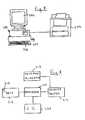
- FIG. 5shows a system, according to an embodiment of the invention, for printing the document of FIG. 1 ;
- FIG. 6shows some of the functional units within the computer of the system of FIG. 5 ;
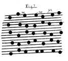
- FIG. 7shows a part of a position identifying pattern and content on a document according to a further embodiment of the invention.
- FIG. 8shows part of a process according to an embodiment of the invention for analysing the pattern and content on the document of FIG. 1 .
- the markings 5which are not shown to scale in FIG. 1 , form a position identifying pattern 6 on the document 2 .
- Also printed on the paper 4are further markings 7 which are clearly visible to a human user of the document, and which make up the content of the document 2 .
- the content 7is in the form of a number of lines which extend over, and are therefore superimposed upon, the pattern 6 .
- the pen 8comprises a writing nib 10 , and a camera 12 made up of an infra red (IR) LED 14 and an IR sensor 16 .
- the camera 12is arranged to image a circular area of diameter 3.3 mm adjacent to the tip 11 of the pen nib 10 .
- a processor 18processes images from the camera 12 taken at a specified sample rate.
- a pressure sensor 20detects when the nib 10 is in contact with the document 2 and triggers operation of the camera 12 .
- the processor 18can determine from the pattern 6 the position of the nib 10 of the pen whenever it is in contact with the document 2 . From this it can determine the position and shape of any marks made on the patterned areas of the document 2 .
- This informationis stored in a memory 22 in the pen as it is being used.
- thisis recorded in a document completion process, for example by making a mark with the pen 8 in a send box 9 .
- the penis arranged to recognise the pattern in the send box 9 and send the pen stoke data to a pen stroke interpretation system in a suitable manner, for example via a radio transceiver 24 which provides a Bluetooth radio link with an internet connected PC.
- Suitable pensare available from Logitech under the trade mark Logitech lo.
- the position identifying pattern 6is made up of a number of graphical elements in the form of black ink dots 30 arranged on an imaginary grid 32 .
- the grid 32which is shown in FIG. 2 for clarity but is not actually marked on the document 2 , can be considered as being made up of horizontal and vertical lines 34 , 36 defining a number of intersections 40 where they cross.
- the intersections 40are of the order of 0.3 mm apart, and the dots 30 are of the order of 100 ⁇ m across.
- One dot 30is provided at each intersection 40 , but offset slightly in one of four possible directions up, down, left or right, from the actual intersection 40 .
- the dot offsetsare arranged to vary in a systematic way so that any group of a sufficient number of dots 30 , for example any group of 36 dots arranged in a six by six square, will be unique within a very large area of the pattern.
- This large areais defined as a total imaginary pattern space, and only a small part of the pattern space is taken up by the pattern on the document 2 .
- the document and any position on the patterned parts of itcan be identified from the pattern printed on it.
- An example of this type of patternis described in WO 01/26033.
- each printer dotis arranged to be larger in diameter than the spacing between the dot centres, so as to ensure that total coverage is achieved in a black area where all of the dots are applied. Therefore the coverage produced by the content dots 50 will be higher than 20%. Assuming the pattern dots are 100 ⁇ m in diameter, they cover about 9% of the area to which they are applied. This means that, to the human eye, the content is clearly visible and distinguishable as a darker shade of grey over the position identifying pattern.
- the processor 18 in the pen 8receives a digital image of the combined pattern and content, as shown in FIG. 3 , from the camera 12 and then processes the image in a known manner to identify the pattern dots 30 .
- the processor 18can identify the pattern dots 30 provided they are within a predetermined size range around 100 ⁇ m diameter, have at least a predetermined contrast with the background, defined as the relative level of absorption of light within a specific range of wavelengths, and are spaced apart with a grid spacing that is within a predetermined range around 300 ⁇ m.
- the pencan still identify the pattern dots 30 where the content 7 is superimposed on the pattern.
- the processoranalyses the positions of the pattern dots 30 and determines from them the position of the imaged area within the total pattern space. This process is then repeated at each sample period, so that the pen can determine the position of pen strokes made on the document 2 as they are made.
- This pen stroke datais stored as in the pen's memory 22 for transmission to a pen stroke interpretation device as described above.
- the density, or grey scale, of the content dotscan vary up to a certain limit, above which the pen 8 is unable to reliably read the pattern 7 .
- a grey scale of from 255 down to about 200which represents about 30% coverage of black ink on a white carrier, can be used with the pen 8 .
- FIG. 4shows an area of a document in which the pattern dots 30 and the content dots 50 are the same size as in FIG. 3 , but the content dots are closer together covering about 75% of the document surface. In this case the contrast between the pattern dots 30 and the surrounding areas of content dots 50 is not sufficient for the pen 8 described above to be able to read the pattern dots.
- a very simple systemfor producing printed documents having the position identifying pattern on them comprises a personal computer (PC) 200 and a printer 202 .
- the PC 200has a screen 204 , a keyboard 206 and a mouse 208 connected to it to provide a user interface 209 as shown generally in FIG. 6 .
- the PC 200comprises a processor 210 and a pattern allocation module 212 which is a software module stored in memory.
- the pattern allocation module 212includes a definition of a total area of pattern space and a record of which parts of that total area have been allocated to specific documents, for example by means of coordinate references.
- the PC 200further comprises a printer driver 214 , which is a further software module, and a memory 216 having electronic documents 218 stored in it.
- the user interface 209allows a user to interact with the PC 200 .
- the printer 202can be any printer which has sufficient resolution to print the pattern dots 30 and the content dots 50 .
- itis a 1200 dots per inch (dpi) monochrome laser jet printer.
- the dimensions of the content dots 50correspond to the dimensions of single pixel of ink from a 1200 dpi printer, and that the spacing between the content dots 50 is twice the spacing of the printer pixels. This enables the printer to print the content dots 50 as single ink dots and the pattern dots 30 as groups of ink dots, for example about 12 dots.
- the printer dotsare not exactly circular but each comprise an irregular mark of ink on the document 2 .
- the exact shape of the content dots 50is not important as the human eye cannot see their shape, and the pattern dots 30 , because they are made up of a group of printer dots, are close enough to a regular shape to be read by the pen 8 . Because they can be distinguished by the pen 8 by virtue of their size, the pattern dots 30 and content dots 50 can be printed using the same type of ink from the monochrome printer. Where a colour printer is used, the ink which is used for the pattern, which would typically be a black ink, can also be used for part of the content where appropriate.
- the processor 210retrieves an electronic document 218 , which may be in the form of a PDF file, from the memory 216 and sends it to the printer driver together with instructions as to whether it is to be printed with pattern or not.
- the electronic document 218contains a definition of the content 7 , and the areas of the document 2 which can have the pattern 6 printed on it.
- the printer driverdetermines from the instructions received whether the document is to be printed with pattern or not. If the document is to be printed without pattern on it, the content is sent for printing. If the document is to be printed with pattern on, the printer driver converts checks the nature of the content to determine whether it is already made up of graphical elements of a suitable format to enable the pattern to be read when the pattern and content are superimposed. If the content is already made up of suitable graphical content elements, then the printing process can proceed. If the content is not suitable made up, for example if it includes areas of solid black, then it is converted so that it is made up entirely of content elements 50 as described above.
- the printer driver 214When it is determined that the content is all in a suitable format, the printer driver 214 requests the required amount of pattern from the pattern allocation module 212 which allocates by means of coordinate references an area of the pattern space to the document, generates the pattern 6 for that area using a pattern generation algorithm, and communicates the details of the pattern including the positions of all the required dots, back to the printer driver 214 .
- the printer driver 214then combines the content 7 and the pattern 6 into a single electronic file. This file therefore forms a combined electronic definition of both the pattern and the content.
- the printer driverthen converts the content 7 and the pattern 6 to a format, such as a postscript file, suitable for the printer 202 , and sends it to the printer which prints the content 7 and the pattern 6 simultaneously in a one-pass process, i.e. on a single pass of the paper, on which the document is printed, through the printer.
- a formatsuch as a postscript file
- the various components of the systemcan be spread out over a local network or the internet.
- the pattern allocation module 212can be provided on a separate internet connected server so that it can be accessed by a number of users.
- FIG. 7shows an example of a document in which the position identifying pattern is again provided by a set of pattern dots 300 , but the content is produced as a set of lines 302 , using the same ink as for the dots.
- the content lines 302are much narrower than the pattern dots 300 and spaced apart by a distance equal to about four times their width. This means that they cover about 20% of the document surface.
- the pattern dotsare again about 100 ⁇ m in diameter and the content lines 302 are about 20 ⁇ m in width and spaced apart at a pitch of about 100 ⁇ m.
- the processor 18is arranged to first receive, at step 300 , an image of a viewed area of the document 2 .
- step 302it performs a Fourier transform on the image which produces a map of the image in the spatial frequency domain.
- the elements of the spatial frequency domain map which correspond to the spatial frequency of the pattern 6are selected, and the elements which correspond to the spatial frequency of the content dots 50 are removed using a low pass filtering process.
- the frequency domain mapis transformed back to a new image, by reverse Fourier transform, to produce an image containing the pattern 6 but not the content 7 .
- the modified imageis then analysed by the processor 18 in the normal way to determine the position of the pattern dots 30 at step 308 .
Landscapes
- Engineering & Computer Science (AREA)
- General Engineering & Computer Science (AREA)
- Theoretical Computer Science (AREA)
- Human Computer Interaction (AREA)
- Physics & Mathematics (AREA)
- General Physics & Mathematics (AREA)
- Editing Of Facsimile Originals (AREA)
- Apparatus For Radiation Diagnosis (AREA)
- Collating Specific Patterns (AREA)
- Image Analysis (AREA)
- Record Information Processing For Printing (AREA)
Abstract
Description
Claims (53)
Priority Applications (2)
| Application Number | Priority Date | Filing Date | Title |
|---|---|---|---|
| US10/661,000US6962450B2 (en) | 2003-09-10 | 2003-09-10 | Methods and apparatus for generating images |
| EP04104288AEP1515265A3 (en) | 2003-09-10 | 2004-09-06 | Method and apparatus for generating images |
Applications Claiming Priority (1)
| Application Number | Priority Date | Filing Date | Title |
|---|---|---|---|
| US10/661,000US6962450B2 (en) | 2003-09-10 | 2003-09-10 | Methods and apparatus for generating images |
Publications (2)
| Publication Number | Publication Date |
|---|---|
| US20050053405A1 US20050053405A1 (en) | 2005-03-10 |
| US6962450B2true US6962450B2 (en) | 2005-11-08 |
Family
ID=34136785
Family Applications (1)
| Application Number | Title | Priority Date | Filing Date |
|---|---|---|---|
| US10/661,000Expired - LifetimeUS6962450B2 (en) | 2003-09-10 | 2003-09-10 | Methods and apparatus for generating images |
Country Status (2)
| Country | Link |
|---|---|
| US (1) | US6962450B2 (en) |
| EP (1) | EP1515265A3 (en) |
Cited By (19)
| Publication number | Priority date | Publication date | Assignee | Title |
|---|---|---|---|---|
| US20040101278A1 (en)* | 2002-11-19 | 2004-05-27 | Canon Kabushiki Kaisha | Recording apparatus capable of recording information representing positions on a recording medium and recording method |
| US20050013104A1 (en)* | 2003-07-18 | 2005-01-20 | Satori Labs, Inc. | Integrated Personal Information Management System |
| US20050211783A1 (en)* | 2003-12-24 | 2005-09-29 | Henwell Chou | Identifier for use with digital paper |
| US20050243373A1 (en)* | 2000-10-20 | 2005-11-03 | Sliverbrook Research Pty Ltd | Graphic design software using an interface surface |
| US20070086032A1 (en)* | 2003-09-10 | 2007-04-19 | Hewlett-Packard Development Company L.P. | Printing of documents with position identification pattern |
| US20070229511A1 (en)* | 1999-10-25 | 2007-10-04 | Silverbrook Research Pty Ltd | Input Unit Arrangement |
| US20080114777A1 (en)* | 2003-09-10 | 2008-05-15 | Hewlett-Packard Development Company, L.P. | Data Structure for an Electronic Document and Related Methods |
| US20080239333A1 (en)* | 2007-03-27 | 2008-10-02 | Oki Data Corporation | Printing system |
| US20090135163A1 (en)* | 1999-10-25 | 2009-05-28 | Silverbrook Research Pty Ltd | System For Digitizing Freehand Graphics On A Printed Surface |
| US20090141112A1 (en)* | 2004-01-15 | 2009-06-04 | Koninklijke Philips Electronics N V | Electronic paint brush with scanner and dispensers |
| US20090309854A1 (en)* | 2008-06-13 | 2009-12-17 | Polyvision Corporation | Input devices with multiple operating modes |
| US20140035880A1 (en)* | 2012-04-26 | 2014-02-06 | Panasonic Corporation | Display control system, pointer, and display panel |
| US8692212B1 (en) | 2012-10-29 | 2014-04-08 | 3M Innovative Properties Company | Optical digitizer system with position-unique photoluminescent indicia |
| US20140231522A1 (en)* | 2011-10-28 | 2014-08-21 | Fujitsu Limited | Image generating method, information processing method, and information processing device |
| US20140315003A1 (en)* | 2011-09-28 | 2014-10-23 | Tomomichi Dougase | Pattern-printed sheet and manufacturing method therefor |
| US9068845B2 (en) | 2011-12-16 | 2015-06-30 | 3M Innovative Properties Company | Optical digitizer system with position-unique photoluminescent indicia |
| US9958954B2 (en) | 2012-12-13 | 2018-05-01 | 3M Innovative Properties Company | System and methods for calibrating a digitizer system |
| US10753746B2 (en) | 2012-11-29 | 2020-08-25 | 3M Innovative Properties, Inc. | Multi-mode stylus and digitizer system |
| US20230196707A1 (en)* | 2020-05-22 | 2023-06-22 | Purdue Research Foundation | Fiducial patterns |
Families Citing this family (9)
| Publication number | Priority date | Publication date | Assignee | Title |
|---|---|---|---|---|
| US20050139666A1 (en)* | 2003-12-24 | 2005-06-30 | Henwell Chou | Verifiable voting input system |
| US7452046B2 (en)* | 2004-10-27 | 2008-11-18 | Hewlett-Packard Development Company, L.P. | Method for preparing a print mask |
| GB2430504A (en)* | 2005-09-15 | 2007-03-28 | Hewlett Packard Development Co | Position encoding pattern with markings which contrast with background content |
| US20070091369A1 (en)* | 2005-10-21 | 2007-04-26 | Hsue-Yang Liu | Printer and printing method |
| JP5263211B2 (en)* | 2010-03-30 | 2013-08-14 | ブラザー工業株式会社 | Server, printer, and computer program for server |
| US9576230B2 (en)* | 2010-07-06 | 2017-02-21 | Marcelo Amaral Rezende | Dot code pattern for absolute position and other information using an optical pen, process of printing the dot code, process of reading the dot code |
| KR101981141B1 (en)* | 2012-04-04 | 2019-08-28 | 삼성전자주식회사 | Method and apparatus for detecting coordinates in a pen-based display device |
| US9443179B2 (en) | 2012-06-19 | 2016-09-13 | The Procter & Gamble Company | Consumer products packaging and methods for producing packaging |
| CN114239773B (en)* | 2021-11-30 | 2024-02-06 | 富联裕展科技(深圳)有限公司 | Material tracking method and material tracking device |
Citations (16)
| Publication number | Priority date | Publication date | Assignee | Title |
|---|---|---|---|---|
| US5337361A (en) | 1990-01-05 | 1994-08-09 | Symbol Technologies, Inc. | Record with encoded data |
| US5841978A (en) | 1993-11-18 | 1998-11-24 | Digimarc Corporation | Network linking method using steganographically embedded data objects |
| US5852434A (en)* | 1992-04-03 | 1998-12-22 | Sekendur; Oral F. | Absolute optical position determination |
| US6098882A (en) | 1996-03-01 | 2000-08-08 | Cobblestone Software, Inc. | Variable formatting of digital data into a pattern |
| WO2000073983A1 (en) | 1999-05-28 | 2000-12-07 | Anoto Ab | Position determination |
| US6164847A (en)* | 1997-01-28 | 2000-12-26 | Agfa Corporation | Imaging parameter detection |
| WO2001026033A1 (en) | 1999-10-01 | 2001-04-12 | Anoto Ab | Position determination - calculation |
| WO2001071643A1 (en) | 2000-03-21 | 2001-09-27 | Anoto Ab | Position information |
| WO2001075773A1 (en) | 2000-04-05 | 2001-10-11 | Anoto Ab | Information-related devices and methods |
| WO2001075783A1 (en) | 2000-04-05 | 2001-10-11 | Anoto Ab | Identification of a virtual raster pattern |
| US20020150276A1 (en) | 1998-08-22 | 2002-10-17 | Chang Kenneth H.P. | Encoding and decoding a message within an image |
| WO2002082366A1 (en) | 2001-04-05 | 2002-10-17 | Anoto Ab | Method for processing information |
| US20020186884A1 (en) | 2001-06-07 | 2002-12-12 | Doron Shaked | Fiducial mark patterns for graphical bar codes |
| US6502756B1 (en)* | 1999-05-28 | 2003-01-07 | Anoto Ab | Recording of information |
| US20030012455A1 (en) | 2001-06-26 | 2003-01-16 | Andreas Olsson | Method and device for data decoding |
| US6586688B2 (en)* | 2000-04-05 | 2003-07-01 | Anoto Ab | Information-related devices and methods |
- 2003
- 2003-09-10USUS10/661,000patent/US6962450B2/ennot_activeExpired - Lifetime
- 2004
- 2004-09-06EPEP04104288Apatent/EP1515265A3/ennot_activeWithdrawn
Patent Citations (19)
| Publication number | Priority date | Publication date | Assignee | Title |
|---|---|---|---|---|
| US5337361C1 (en) | 1990-01-05 | 2001-05-15 | Symbol Technologies Inc | Record with encoded data |
| US5337361A (en) | 1990-01-05 | 1994-08-09 | Symbol Technologies, Inc. | Record with encoded data |
| US5852434A (en)* | 1992-04-03 | 1998-12-22 | Sekendur; Oral F. | Absolute optical position determination |
| US5841978A (en) | 1993-11-18 | 1998-11-24 | Digimarc Corporation | Network linking method using steganographically embedded data objects |
| US6098882A (en) | 1996-03-01 | 2000-08-08 | Cobblestone Software, Inc. | Variable formatting of digital data into a pattern |
| US6164847A (en)* | 1997-01-28 | 2000-12-26 | Agfa Corporation | Imaging parameter detection |
| US20020150276A1 (en) | 1998-08-22 | 2002-10-17 | Chang Kenneth H.P. | Encoding and decoding a message within an image |
| WO2000073983A1 (en) | 1999-05-28 | 2000-12-07 | Anoto Ab | Position determination |
| US6502756B1 (en)* | 1999-05-28 | 2003-01-07 | Anoto Ab | Recording of information |
| WO2001026033A1 (en) | 1999-10-01 | 2001-04-12 | Anoto Ab | Position determination - calculation |
| US6674427B1 (en)* | 1999-10-01 | 2004-01-06 | Anoto Ab | Position determination II—calculation |
| WO2001071643A1 (en) | 2000-03-21 | 2001-09-27 | Anoto Ab | Position information |
| US6689966B2 (en)* | 2000-03-21 | 2004-02-10 | Anoto Ab | System and method for determining positional information |
| WO2001075783A1 (en) | 2000-04-05 | 2001-10-11 | Anoto Ab | Identification of a virtual raster pattern |
| US6586688B2 (en)* | 2000-04-05 | 2003-07-01 | Anoto Ab | Information-related devices and methods |
| WO2001075773A1 (en) | 2000-04-05 | 2001-10-11 | Anoto Ab | Information-related devices and methods |
| WO2002082366A1 (en) | 2001-04-05 | 2002-10-17 | Anoto Ab | Method for processing information |
| US20020186884A1 (en) | 2001-06-07 | 2002-12-12 | Doron Shaked | Fiducial mark patterns for graphical bar codes |
| US20030012455A1 (en) | 2001-06-26 | 2003-01-16 | Andreas Olsson | Method and device for data decoding |
Non-Patent Citations (8)
| Title |
|---|
| "Anoto Pattern & Digital Paper" Internet: <<http://www.anotofunctionality.com/navigate.asp?PageID=73>> 1 page total (Jan. 19, 2004). |
| "Construction" Internet: <<http://web.archive.org/web/20030623220554/www/anoto.com/?url=/technology/patter . . . 1 page total (Jan. 19, 2004). |
| "How does it work?" Internet: <<http://www.anotofunctionality.com/navigate.asp?PageID=24>> 1 page total (Jan. 19, 2004). |
| "The Technologies Behind Anoto Functionality" Internet: <<http://web.archive.org/web/20030622071228/www.anoto.com/?url;=/technology/1 page total (Jan. 19, 2004). |
| Anoto Home Page Internet:: <<http:://www.anoto.com>> pp. 1-2 (Jan. 19, 2004). |
| U.S. Appl. No. 10/660,323, filed Sep. 10, 2003, Nelson. |
| U.S. Appl. No. 10/660,324, filed Sep. 10, 2003, Nelson et al. |
| U.S. Appl. No. 10/661,001, filed Sep. 10, 2003, Mackenzie et al. |
Cited By (41)
| Publication number | Priority date | Publication date | Assignee | Title |
|---|---|---|---|---|
| US7503493B2 (en) | 1999-10-25 | 2009-03-17 | Silverbrook Research Pty Ltd | Method and system for digitizing freehand graphics with user-selected properties |
| US20090135163A1 (en)* | 1999-10-25 | 2009-05-28 | Silverbrook Research Pty Ltd | System For Digitizing Freehand Graphics On A Printed Surface |
| US8091787B2 (en) | 1999-10-25 | 2012-01-10 | Silverbrook Research Pty Ltd | Processing system for digitizing freehand graphics |
| US7832640B2 (en) | 1999-10-25 | 2010-11-16 | Silverbrook Research Pty Ltd | System for digitizing freehand graphics on a printed surface |
| US20110174882A1 (en)* | 1999-10-25 | 2011-07-21 | Silverbrook Research Pty Ltd | Processing system for digitizing freehand graphics |
| US7934655B2 (en) | 1999-10-25 | 2011-05-03 | Silverbrook Research Pty Ltd | Input arrangement for controlling electronic device |
| US20090267915A1 (en)* | 1999-10-25 | 2009-10-29 | Silverbrook Research Pty Ltd | Input arrangement for controlling electronic device |
| US20070229511A1 (en)* | 1999-10-25 | 2007-10-04 | Silverbrook Research Pty Ltd | Input Unit Arrangement |
| US7568622B2 (en) | 1999-10-25 | 2009-08-04 | Silverbrook Research Pty Ltd | Input unit arrangement |
| US20110024492A1 (en)* | 1999-10-25 | 2011-02-03 | Silverbrook Research Pty Ltd | Digitizing system having printed base, imaging pen and relay device |
| US7934656B2 (en) | 1999-10-25 | 2011-05-03 | Silverbrook Research Pty Ltd | Digitizing system having printed base, imaging pen and relay device |
| US7322524B2 (en)* | 2000-10-20 | 2008-01-29 | Silverbrook Research Pty Ltd | Graphic design software using an interface surface |
| US20050243373A1 (en)* | 2000-10-20 | 2005-11-03 | Sliverbrook Research Pty Ltd | Graphic design software using an interface surface |
| US20040101278A1 (en)* | 2002-11-19 | 2004-05-27 | Canon Kabushiki Kaisha | Recording apparatus capable of recording information representing positions on a recording medium and recording method |
| US7773377B2 (en)* | 2003-07-18 | 2010-08-10 | Satori Labs, Inc. | Integrated personal information management system |
| US20080012839A1 (en)* | 2003-07-18 | 2008-01-17 | Satori Labs, Inc. | Integrated Personal Information Management System |
| US20050013104A1 (en)* | 2003-07-18 | 2005-01-20 | Satori Labs, Inc. | Integrated Personal Information Management System |
| US7245483B2 (en)* | 2003-07-18 | 2007-07-17 | Satori Labs, Inc. | Integrated personal information management system |
| US20080114777A1 (en)* | 2003-09-10 | 2008-05-15 | Hewlett-Packard Development Company, L.P. | Data Structure for an Electronic Document and Related Methods |
| US20070086032A1 (en)* | 2003-09-10 | 2007-04-19 | Hewlett-Packard Development Company L.P. | Printing of documents with position identification pattern |
| US8130391B2 (en)* | 2003-09-10 | 2012-03-06 | Hewlett-Packard Development Company L.P. | Printing of documents with position identification pattern |
| US7134606B2 (en)* | 2003-12-24 | 2006-11-14 | Kt International, Inc. | Identifier for use with digital paper |
| US20050211783A1 (en)* | 2003-12-24 | 2005-09-29 | Henwell Chou | Identifier for use with digital paper |
| US7815305B2 (en)* | 2004-01-15 | 2010-10-19 | Koninklijke Philips Electronics N.V. | Electronic paint brush with scanner and dispensers |
| US20090141112A1 (en)* | 2004-01-15 | 2009-06-04 | Koninklijke Philips Electronics N V | Electronic paint brush with scanner and dispensers |
| US20080239333A1 (en)* | 2007-03-27 | 2008-10-02 | Oki Data Corporation | Printing system |
| US20090309854A1 (en)* | 2008-06-13 | 2009-12-17 | Polyvision Corporation | Input devices with multiple operating modes |
| US10739915B2 (en)* | 2011-09-28 | 2020-08-11 | Dai Nippon Printing Co., Ltd. | Pattern-printed sheet and manufacturing method therefor |
| US20140315003A1 (en)* | 2011-09-28 | 2014-10-23 | Tomomichi Dougase | Pattern-printed sheet and manufacturing method therefor |
| US20140231522A1 (en)* | 2011-10-28 | 2014-08-21 | Fujitsu Limited | Image generating method, information processing method, and information processing device |
| US9235743B2 (en)* | 2011-10-28 | 2016-01-12 | Fujitsu Limited | Image generating method, information processing method, and information processing device |
| US9068845B2 (en) | 2011-12-16 | 2015-06-30 | 3M Innovative Properties Company | Optical digitizer system with position-unique photoluminescent indicia |
| US9557827B2 (en) | 2011-12-16 | 2017-01-31 | 3M Innovative Properties Company | Optical digitizer system with position-unique photoluminescent indicia |
| US9442653B2 (en)* | 2012-04-26 | 2016-09-13 | Panasonic Intellectual Property Management Co., Ltd. | Display control system, pointer, and display panel |
| US20140035880A1 (en)* | 2012-04-26 | 2014-02-06 | Panasonic Corporation | Display control system, pointer, and display panel |
| US8692212B1 (en) | 2012-10-29 | 2014-04-08 | 3M Innovative Properties Company | Optical digitizer system with position-unique photoluminescent indicia |
| US9075452B2 (en) | 2012-10-29 | 2015-07-07 | 3M Innovative Properties Company | Optical digitizer system with position-unique photoluminescent indicia |
| US9836164B2 (en) | 2012-10-29 | 2017-12-05 | 3M Innovative Properties Company | Optical digitizer system with position-unique photoluminescent indicia |
| US10753746B2 (en) | 2012-11-29 | 2020-08-25 | 3M Innovative Properties, Inc. | Multi-mode stylus and digitizer system |
| US9958954B2 (en) | 2012-12-13 | 2018-05-01 | 3M Innovative Properties Company | System and methods for calibrating a digitizer system |
| US20230196707A1 (en)* | 2020-05-22 | 2023-06-22 | Purdue Research Foundation | Fiducial patterns |
Also Published As
| Publication number | Publication date |
|---|---|
| EP1515265A2 (en) | 2005-03-16 |
| EP1515265A3 (en) | 2005-04-27 |
| US20050053405A1 (en) | 2005-03-10 |
Similar Documents
| Publication | Publication Date | Title |
|---|---|---|
| US6962450B2 (en) | Methods and apparatus for generating images | |
| US20050052700A1 (en) | Printing digital documents | |
| US7517041B2 (en) | Printing and detecting a fixer pattern on a medium | |
| US20050253743A1 (en) | Method for making a product | |
| JP2004528644A (en) | How to process information | |
| CA2374723A1 (en) | Computer system interface surface | |
| US20060283962A1 (en) | Data encoding pattern | |
| EP2591441B1 (en) | Dot code pattern for absolute position and other information using an optical pen, process of printing the dot code, process of reading the dot code | |
| US20070076953A1 (en) | Data-encoding pattern, system and method | |
| US8509572B2 (en) | Handwriting recognition using an electronic stylus | |
| US20070273918A1 (en) | Printing Digital Documents | |
| US7542607B2 (en) | Digital pen and paper | |
| US20050052706A1 (en) | Location patterns and methods and apparatus for generating such patterns | |
| US7792365B2 (en) | Methods and apparatus for generating images | |
| US8130391B2 (en) | Printing of documents with position identification pattern | |
| US20050212779A1 (en) | Position identification pattern | |
| US7559484B2 (en) | Products with data encoding pattern | |
| US8100338B2 (en) | Data encoding pattern | |
| GB2428502A (en) | Data encoding pattern | |
| WO2005024618A1 (en) | Generation and processing of position identification pattern | |
| WO2005076194A2 (en) | Products with position identification pattern | |
| WO2005024619A2 (en) | Products with position identification pattern | |
| WO2005024701A2 (en) | Creation of documents with position identification pattern | |
| GB2421617A (en) | Products with data encoding pattern | |
| GB2430504A (en) | Position encoding pattern with markings which contrast with background content |
Legal Events
| Date | Code | Title | Description |
|---|---|---|---|
| AS | Assignment | Owner name:HEWLETT-PACKARD DEVELOPMENT COMPANY, L.P., TEXAS Free format text:ASSIGNMENT OF ASSIGNORS INTEREST;ASSIGNOR:HEWLETT-PACKARD COMPANY;REEL/FRAME:016050/0887 Effective date:20050412 | |
| AS | Assignment | Owner name:HEWLETT-PACKARD DEVELOPMENT COMPANY, L.P., TEXAS Free format text:ASSIGNMENT OF ASSIGNORS INTEREST;ASSIGNORS:HP CENTRE DE COMPETENCES FRANCE S.A.S.;BROUHON, PATRICK;REEL/FRAME:016150/0245 Effective date:20040621 Owner name:HEWLETT-PACKARD COMPANY, CALIFORNIA Free format text:COPY OF EMPLOYEE AGREEMENT OF IRA GOLDSTEIN WITH HEWLETT-PACKARD COMPANY;ASSIGNOR:GOLDSTEIN, IRA;REEL/FRAME:016150/0248 Effective date:19810803 | |
| STCF | Information on status: patent grant | Free format text:PATENTED CASE | |
| FPAY | Fee payment | Year of fee payment:4 | |
| CC | Certificate of correction | ||
| FPAY | Fee payment | Year of fee payment:8 | |
| REMI | Maintenance fee reminder mailed | ||
| FEPP | Fee payment procedure | Free format text:11.5 YR SURCHARGE- LATE PMT W/IN 6 MO, LARGE ENTITY (ORIGINAL EVENT CODE: M1556) | |
| MAFP | Maintenance fee payment | Free format text:PAYMENT OF MAINTENANCE FEE, 12TH YEAR, LARGE ENTITY (ORIGINAL EVENT CODE: M1553) Year of fee payment:12 |