US6961555B1 - System and apparatus for connecting a wireless device to a remote location on a network - Google Patents
System and apparatus for connecting a wireless device to a remote location on a networkDownload PDFInfo
- Publication number
- US6961555B1 US6961555B1US09/703,465US70346500AUS6961555B1US 6961555 B1US6961555 B1US 6961555B1US 70346500 AUS70346500 AUS 70346500AUS 6961555 B1US6961555 B1US 6961555B1
- Authority
- US
- United States
- Prior art keywords
- wireless device
- beacon signal
- information
- code
- accordance
- Prior art date
- Legal status (The legal status is an assumption and is not a legal conclusion. Google has not performed a legal analysis and makes no representation as to the accuracy of the status listed.)
- Expired - Lifetime, expires
Links
Images


Classifications
- G—PHYSICS
- G06—COMPUTING OR CALCULATING; COUNTING
- G06Q—INFORMATION AND COMMUNICATION TECHNOLOGY [ICT] SPECIALLY ADAPTED FOR ADMINISTRATIVE, COMMERCIAL, FINANCIAL, MANAGERIAL OR SUPERVISORY PURPOSES; SYSTEMS OR METHODS SPECIALLY ADAPTED FOR ADMINISTRATIVE, COMMERCIAL, FINANCIAL, MANAGERIAL OR SUPERVISORY PURPOSES, NOT OTHERWISE PROVIDED FOR
- G06Q30/00—Commerce
- G06Q30/02—Marketing; Price estimation or determination; Fundraising
- G—PHYSICS
- G06—COMPUTING OR CALCULATING; COUNTING
- G06F—ELECTRIC DIGITAL DATA PROCESSING
- G06F16/00—Information retrieval; Database structures therefor; File system structures therefor
- G06F16/90—Details of database functions independent of the retrieved data types
- G06F16/95—Retrieval from the web
- G06F16/955—Retrieval from the web using information identifiers, e.g. uniform resource locators [URL]
- G06F16/9554—Retrieval from the web using information identifiers, e.g. uniform resource locators [URL] by using bar codes
- G—PHYSICS
- G06—COMPUTING OR CALCULATING; COUNTING
- G06F—ELECTRIC DIGITAL DATA PROCESSING
- G06F16/00—Information retrieval; Database structures therefor; File system structures therefor
- G06F16/90—Details of database functions independent of the retrieved data types
- G06F16/95—Retrieval from the web
- G06F16/955—Retrieval from the web using information identifiers, e.g. uniform resource locators [URL]
- G06F16/9566—URL specific, e.g. using aliases, detecting broken or misspelled links
- H—ELECTRICITY
- H04—ELECTRIC COMMUNICATION TECHNIQUE
- H04H—BROADCAST COMMUNICATION
- H04H20/00—Arrangements for broadcast or for distribution combined with broadcast
- H04H20/86—Arrangements characterised by the broadcast information itself
- H04H20/93—Arrangements characterised by the broadcast information itself which locates resources of other pieces of information, e.g. URL [Uniform Resource Locator]
- H—ELECTRICITY
- H04—ELECTRIC COMMUNICATION TECHNIQUE
- H04L—TRANSMISSION OF DIGITAL INFORMATION, e.g. TELEGRAPHIC COMMUNICATION
- H04L61/00—Network arrangements, protocols or services for addressing or naming
- H—ELECTRICITY
- H04—ELECTRIC COMMUNICATION TECHNIQUE
- H04L—TRANSMISSION OF DIGITAL INFORMATION, e.g. TELEGRAPHIC COMMUNICATION
- H04L61/00—Network arrangements, protocols or services for addressing or naming
- H04L61/30—Managing network names, e.g. use of aliases or nicknames
- H—ELECTRICITY
- H04—ELECTRIC COMMUNICATION TECHNIQUE
- H04L—TRANSMISSION OF DIGITAL INFORMATION, e.g. TELEGRAPHIC COMMUNICATION
- H04L61/00—Network arrangements, protocols or services for addressing or naming
- H04L61/30—Managing network names, e.g. use of aliases or nicknames
- H04L61/301—Name conversion
- H—ELECTRICITY
- H04—ELECTRIC COMMUNICATION TECHNIQUE
- H04L—TRANSMISSION OF DIGITAL INFORMATION, e.g. TELEGRAPHIC COMMUNICATION
- H04L61/00—Network arrangements, protocols or services for addressing or naming
- H04L61/45—Network directories; Name-to-address mapping
- H—ELECTRICITY
- H04—ELECTRIC COMMUNICATION TECHNIQUE
- H04L—TRANSMISSION OF DIGITAL INFORMATION, e.g. TELEGRAPHIC COMMUNICATION
- H04L67/00—Network arrangements or protocols for supporting network services or applications
- H04L67/01—Protocols
- H04L67/02—Protocols based on web technology, e.g. hypertext transfer protocol [HTTP]
- H—ELECTRICITY
- H04—ELECTRIC COMMUNICATION TECHNIQUE
- H04L—TRANSMISSION OF DIGITAL INFORMATION, e.g. TELEGRAPHIC COMMUNICATION
- H04L67/00—Network arrangements or protocols for supporting network services or applications
- H04L67/2866—Architectures; Arrangements
- H04L67/30—Profiles
- H04L67/306—User profiles
- H—ELECTRICITY
- H04—ELECTRIC COMMUNICATION TECHNIQUE
- H04L—TRANSMISSION OF DIGITAL INFORMATION, e.g. TELEGRAPHIC COMMUNICATION
- H04L67/00—Network arrangements or protocols for supporting network services or applications
- H04L67/50—Network services
- H04L67/53—Network services using third party service providers
- H—ELECTRICITY
- H04—ELECTRIC COMMUNICATION TECHNIQUE
- H04L—TRANSMISSION OF DIGITAL INFORMATION, e.g. TELEGRAPHIC COMMUNICATION
- H04L67/00—Network arrangements or protocols for supporting network services or applications
- H04L67/50—Network services
- H04L67/55—Push-based network services
- H—ELECTRICITY
- H04—ELECTRIC COMMUNICATION TECHNIQUE
- H04N—PICTORIAL COMMUNICATION, e.g. TELEVISION
- H04N21/00—Selective content distribution, e.g. interactive television or video on demand [VOD]
- H04N21/40—Client devices specifically adapted for the reception of or interaction with content, e.g. set-top-box [STB]; Operations thereof
- H04N21/45—Management operations performed by the client for facilitating the reception of or the interaction with the content or administrating data related to the end-user or to the client device itself, e.g. learning user preferences for recommending movies, resolving scheduling conflicts
- H04N21/462—Content or additional data management, e.g. creating a master electronic program guide from data received from the Internet and a Head-end, controlling the complexity of a video stream by scaling the resolution or bit-rate based on the client capabilities
- H04N21/4622—Retrieving content or additional data from different sources, e.g. from a broadcast channel and the Internet
- H—ELECTRICITY
- H04—ELECTRIC COMMUNICATION TECHNIQUE
- H04N—PICTORIAL COMMUNICATION, e.g. TELEVISION
- H04N21/00—Selective content distribution, e.g. interactive television or video on demand [VOD]
- H04N21/40—Client devices specifically adapted for the reception of or interaction with content, e.g. set-top-box [STB]; Operations thereof
- H04N21/47—End-user applications
- H04N21/478—Supplemental services, e.g. displaying phone caller identification, shopping application
- H04N21/4782—Web browsing, e.g. WebTV
- H—ELECTRICITY
- H04—ELECTRIC COMMUNICATION TECHNIQUE
- H04N—PICTORIAL COMMUNICATION, e.g. TELEVISION
- H04N21/00—Selective content distribution, e.g. interactive television or video on demand [VOD]
- H04N21/80—Generation or processing of content or additional data by content creator independently of the distribution process; Content per se
- H04N21/81—Monomedia components thereof
- H04N21/812—Monomedia components thereof involving advertisement data
- H—ELECTRICITY
- H04—ELECTRIC COMMUNICATION TECHNIQUE
- H04W—WIRELESS COMMUNICATION NETWORKS
- H04W76/00—Connection management
- H04W76/10—Connection setup
- H04W76/11—Allocation or use of connection identifiers
- H—ELECTRICITY
- H04—ELECTRIC COMMUNICATION TECHNIQUE
- H04L—TRANSMISSION OF DIGITAL INFORMATION, e.g. TELEGRAPHIC COMMUNICATION
- H04L69/00—Network arrangements, protocols or services independent of the application payload and not provided for in the other groups of this subclass
- H04L69/30—Definitions, standards or architectural aspects of layered protocol stacks
- H04L69/32—Architecture of open systems interconnection [OSI] 7-layer type protocol stacks, e.g. the interfaces between the data link level and the physical level
- H04L69/322—Intralayer communication protocols among peer entities or protocol data unit [PDU] definitions
- H04L69/329—Intralayer communication protocols among peer entities or protocol data unit [PDU] definitions in the application layer [OSI layer 7]
- H—ELECTRICITY
- H04—ELECTRIC COMMUNICATION TECHNIQUE
- H04M—TELEPHONIC COMMUNICATION
- H04M1/00—Substation equipment, e.g. for use by subscribers
- H04M1/72—Mobile telephones; Cordless telephones, i.e. devices for establishing wireless links to base stations without route selection
- H04M1/724—User interfaces specially adapted for cordless or mobile telephones
- H04M1/72403—User interfaces specially adapted for cordless or mobile telephones with means for local support of applications that increase the functionality
- H04M1/72445—User interfaces specially adapted for cordless or mobile telephones with means for local support of applications that increase the functionality for supporting Internet browser applications
- H—ELECTRICITY
- H04—ELECTRIC COMMUNICATION TECHNIQUE
- H04W—WIRELESS COMMUNICATION NETWORKS
- H04W48/00—Access restriction; Network selection; Access point selection
- H04W48/08—Access restriction or access information delivery, e.g. discovery data delivery
- H—ELECTRICITY
- H04—ELECTRIC COMMUNICATION TECHNIQUE
- H04W—WIRELESS COMMUNICATION NETWORKS
- H04W48/00—Access restriction; Network selection; Access point selection
- H04W48/16—Discovering, processing access restriction or access information
Definitions
- This inventionis related to an apparatus for computer control in one aspect, it relates to an apparatus for automatically connecting a nearby wireless device to a remote location on a computer network.
- an advertiserdesires to provide the user of a wireless device with information or knowledge which is especially relevant to the user's current geographic location, e.g., nearby restaurants or shopping opportunities. Further, unless the user of a wireless device has a GPS or other positioning system available, the user typically does not know precisely what his or her current geographic location is. A need therefore exists, for a system for connecting a wireless device to a remote location on a network which is associated with the current geographic location of the wireless device, without requiring the wireless device or its user to provide any geographic location information.
- the present invention disclosed and claimed hereincomprises, in one aspect thereof, a system for connecting a wireless device to a remote location on a computer network.
- the wireless deviceincludes a processor and a transmitter/receiver for sending and receiving radio frequency signals to provide two-way digital communication between the processor and the computer network.
- the systemcomprises a beacon unit and a beacon signal receiver circuit.
- the beacon unitis disposed at a location and includes a transmitter which transmits a beacon signal into a target region adjacent to the location
- the beacon signal receiver circuitis disposed with the wireless device and adapted to receive the beacon signal when the wireless device is within the target region.
- the beacon signal receiver circuitis operably connected to the processor of the wireless device. In response to receiving the beacon signal, the beacon signal receiver circuit sends control control signals, the wireless device is connected to a remote location on the computer network.
- FIG. 1illustrates a block diagram of the preferred embodiment
- FIG. 2illustrates the computer components employed in this embodiment
- FIG. 3illustrates system interactions over a global network
- FIGS. 4 a - 4 eillustrate the various message packets transmitted between the source PC and network servers used in the preferred embodiment
- FIG. 5is a flowchart depicting operation of the system according to the preferred embodiment
- FIG. 6illustrates a flowchart of actions taken by the Advertiser Reference Server (“ARS”) server
- FIG. 7illustrates a flowchart of the interactive process between the source computer and ARS
- FIG. 8illustrates a web browser page receiving the modified URL/advertiser product data according to the preferred embodiment
- FIG. 9illustrates a simplified block diagram of the disclosed embodiment
- FIG. 10illustrates a more detailed, simplified block diagram of the embodiment of FIG. 9 ;
- FIG. 11illustrates a diagrammatic view of a method for performing the routing operation
- FIG. 12illustrates a block diagram of an alternate embodiment utilizing an optical region in the video image for generating the routing information
- FIG. 13illustrates a block diagram illustrating the generation of a profile with the disclosed embodiment
- FIG. 14illustrates a flowchart for generating the profile and storing at the ARS
- FIG. 15illustrates a flowchart for processing the profile information when information is routed to a user
- FIG. 16illustrates a general block diagram of a disclosed embodiment
- FIG. 17illustrates the conversion circuit of the wedge interface
- FIG. 18illustrates a sample message packet transmitted from the user PC to the ARS
- FIG. 19illustrates a more detailed block diagram of the routing of the message packets between the various nodes
- FIG. 20illustrates a block diagram of a browser window, according to a disclosed embodiment
- FIG. 21illustrates a diagrammatic view of information contained in the ARS database
- FIG. 22illustrates a flowchart of the process of receiving information from the user's perspective
- FIG. 23illustrates a flowchart according to the ARS
- FIG. 24illustrates a flowchart of the process performed at the E-commerce node
- FIG. 25illustrates a diagrammatic view of a system for connecting a wireless device to a remote location on a network in accordance with another embodiment
- FIG. 26illustrates a diagrammatic view of one embodiment of a beacon unit
- FIG. 27illustrates a diagrammatic view of one embodiment of a beacon signal receiver circuit and the associated wireless device
- FIGS. 28 a - 28 dillustrate a flowchart of a process for connecting a wireless device to a remote location on a computer network in accordance with another embodiment
- FIG. 29is a plan view of a geographic region containing an embodiment of the invention.
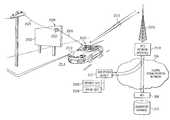
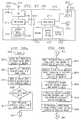
- FIG. 1there is illustrated a block diagram of a system for controlling a personal computer (“PC”) 112 via an audio tone transmitted over a wireless system utilizing a TV.
- PCpersonal computer
- the transmission station 101is comprised of a television program source 104 , which is operable to generate a program in the form of a broadcast signal comprised of video and audio. This is transmitted via conventional techniques along channels in the appropriate frequencies.
- the program sourceis input to a mixing device 106 , which mixing device is operable to mix in an audio signal.
- This audio signalis derived from an audio source 100 which comprises a coded audio signal which is then modulated onto a carrier which is combined with the television program source 104 .
- This signal combiningcan be done at the audio level, or it can even be done at the RF level in the form of a different carrier.
- the preferred methodis to merely sum the audio signal from the modulator 102 into the audio channel of the program that is generated by the television program source 104 .
- the output thereofis provided from the mixing device 106 in the form of broadcast signal to an antenna 107 , which transmits the information over the communication link 108 to an antenna 109 on the receive side.
- a conventional receiver 110such as a television is provided.
- This televisionprovides a speaker output which provides the user with an audible signal.
- Thisis typically associated with the program.
- the receiver 110 in the disclosed embodimentalso provides an audio output jack, this being the type RCA jack.
- This jackis utilized to provide an audio output signal on a line 113 which is represented by an audio signal 111 .
- This line 113provides all of the audio that is received over the communication link 108 to the PC 112 in the audio input port on the PC 112 .
- the audio signal generated by the advertiser data input device 100is audible to the human ear and, therefore, can be heard by the user. Therefore, no special filters are needed to provide this audio to the PC 112 .
- the PC 112is operable to run programs thereon which typically are stored in a program file area 116 . These programs can be any type of programs such as word processing programs, application programs, etc. In the disclosed embodiment, the program that is utilized in the system is what is referred to as a “browser.”
- the PC 112runs a browser program into facilitate the access of information on the network, for example, a global communication network known as the “Internet” or the World-Wide-Web (“Web”).
- the browseris a hypertext-linked application used for accessing information. Hypertext is a term used to describe a particular organization of information within a data processing system, and its presentation to a user.
- Hypertext systemsuse a large number of units of text or other types of data such as image information, graphical information, video information, or sound information, which can vary in size.
- a collection of such units of informationis termed a hypertext document, or where the hypertext documents employ information other than text, hypermedia documents.
- Multimedia communicationsmay use the Hypertext Transfer Protocol (“HTTP”), and files or formatted data may use the Hypertext Markup Language (“HTML”).
- HTTPHypertext Transfer Protocol
- HTMLHypertext Markup Language
- This formatting languageprovides for a mingling of text, graphics, sound, video, and hypertext links by “tagging” a text document using HTML.
- Data encoded using HTMLis often referred to as an “HTML document,” an “HTML page,” or a “home page.”
- HTML documentData encoded using HTML
- HTML pageData encoded using HTML
- home pageThese documents and other Internet resources may be accessed across the network by means of a network addressing scheme which uses a locator referred to as a Uniform Resource Locator (“URL”), for example, “http://www.digital.com.”
- URLUniform Resource Locator
- the Internetis one of the most utilized networks for interconnecting distributed computer systems and allows users of these computer systems to exchange data all over the world.
- Many private networksfor example, corporate or commercial networks.
- Standard protocolssuch as the Transport Control Protocol (“TCP”) and the Internet Protocol (“IP”) provide a convenient method for communicating across these diverse networks. These protocols dictate how data are formatted and communicated.
- TCPTransport Control Protocol
- IPInternet Protocol
- the protocolsare layered in an IP stack. At higher levels of the IP stack, such as the application layer (where HTTP is employed), the user information is more readily visible, while at lower levels, such as the network level (where TCP/IP are used), the data can merely be observed as packets or a stream of rapidly moving digital signals.
- Superimposed on the Internetis a standard protocol interface for accessing Web resources, such as servers, files, Web pages, mail messages, and the like. One way that Web resources can be accessed is by browsers made by Netscape® and Microsoft Internet Explorer®.
- the usercan load this program with the appropriate keystrokes such that a browser window will be displayed on a display 118 .
- the usercan run the browser program on the PC 112 such that the browser window is displayed on the display 118 .
- the usercan also view display 118 .
- the first operationis to extract the audio information within the received audio signal in the form of digital data, and then transmit this digital data to a defined location on the global communication network via a modem connection 114 . This connection will be described hereinbelow.
- This informationwill be relayed to a proprietary location and the instructions sent back to the PC 112 as to the location of the advertiser associated with the code, and the PC 112 will then effect a communication link to that location such that the user can view on the display 118 information that the advertiser, by the fact of putting the tone onto the broadcast channel, desires the viewer to view.
- This informationcan be in the form of interactive programs, data files, etc.
- the tonewhen an advertisement appears on the television, the tone can be generated and then additional data displayed on the display 118 .
- a streaming video programcould be played on the PC received over the network, which streaming video program is actually longer than the advertising segment on the broadcast.
- Another examplewould be a sports game that would broadcast the tone in order to allow a user access to information that is not available over the broadcast network, such as additional statistics associated with the sports program, etc.
- an advertiseris allowed the ability to control a user's PC 112 through the use of tones embedded within a program audio signal.
- the disclosed embodimentutilizes particular routing information stored in the PC 112 which allows the encoded information in the received audio signal to route this information to a desired location on the network, and then allow other routing information to be returned to the PC 112 for control thereof to route the PC 112 to the appropriate location associated with that code.
- the computer 204comprises an internal audio or “sound” card 206 for receiving the transmitted audio signal through receive antenna 109 and receiver 110 .
- the sound card 206typically contains analog-to-digital circuitry for converting the analog audio signal into a digital signal. The digital signal may then be more easily manipulated by software programs.
- the receiver 110separates the audio signal from the video signal.
- a special trigger signal located within the transmitted advertiser audio signaltriggers proprietary software running on the computer 204 which launches a communication application, in this particular embodiment, the web browser application located on the PC 204 . Coded advertiser information contained within the audio signal is then extracted and appended with the address of a proprietary server located on the communication network.
- the remote server addressis in the form of a URL.
- This appended datain addition to other control codes, is inserted directly into the web browser application for automatic routing to the communication network.
- the web browser running on PC 204and communicating to the network with an internal modem 208 , in this embodiment, transmits the advertiser information to the remote server.
- the remote servercross-references the advertiser product information to the address of the advertiser server located on the network.
- the address of the advertiser serveris routed back through the PC 204 web browser to the advertiser server.
- the advertiser product informationis returned to PC 204 to be presented to the viewer on display 118 .
- the particular advertiser product information displayedis contained within the advertiser's web page 212 .
- the audio signalis audible to the human ear. Therefore the audio signal, as emitted from the TV speakers, may be input to the sound card 206 via a microphone. Furthermore, the audio signal need not beta real-time broadcast, but may be on video tapes, CDS, DVD, or other media which may be displayed at a later date. With the imminent implementation of high definition digital television, the audio signal output from the TV may also be digital. Therefore, direct input into a sound card for A/D purposes may not be necessary, but alternative interfacing techniques to accommodate digital-to-digital signal formats would apply.
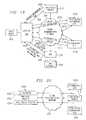
- a source PC 302similar to PCS 204 and 112 , connected to a global communication network (“GCN”) 306 through an interface 304 .
- the audio signal 111is received by PC 302 through its sound card 206 .
- the audio signal 111comprises a trigger signal which triggers proprietary software into launching a web browser application residing on the PC 302 .
- the audio signal 111also comprises advertiser product information which is extracted and appended with URL information of an Advertiser Reference Server (“ARS”) 308 .
- ARS 308is a system disposed on the GCN 306 that is defined as the location to which data in the audio signal 111 is to be routed.
- data in the audio signal 111will always be routed to the ARS 308 , since a URL is unique on the GCN 306 .
- a database 310 of product codes and associated manufacturer URLsConnected to the ARS 308 is a database 310 of product codes and associated manufacturer URLs.
- the database 310undergoes a continual update process which is transparent to the user. As companies sign-on, i.e., subscribe, to this technology, manufacturer and product information is added to the database 310 without interrupting operation of the source PC 302 with frequent updates.
- the advertiser server address URLis obtained from the ARS database 310 , it and the request for the particular advertiser product information are automatically routed back through the web browser on PC 302 , over to the respective advertiser server for retrieval of the advertiser product information to the PC 302 .
- the disclosed inventiondiscusses a global communication network, the system is also applicable to LANs, WANs, and peer-to-peer network configurations. It should be noted that the disclosed architecture is not limited to a single source PC 302 , but may comprise a plurality of source PCS, e.g., PC 300 and PC 303 . Moreover, a plurality of ARS 308 systems and advertiser servers 312 may be implemented, e.g., ARS 314 , and advertiser server. A 316 , respectively.
- the information transactionsin general, which occur between the networked systems of this embodiment, over the communication network, are the following.
- the web browser running on source PC 302transmits a message packet to the ARS 308 over Path “A.”
- the ARS 308decodes the message packet and performs a cross-reference function with product information extracted from the received message packet to obtain the address of an advertiser server 312 .
- a new message packetis assembled comprising the advertiser server 312 address, and sent back to the source PC 302 over Path “B.”
- a “handoff” operationis performed whereby the source PC 302 browser simply reroutes the information on to the advertiser server 312 over Path “C,” with the appropriate source and destination address appended.
- the advertiser server 312receives and decodes the message packet.
- the request-for-advertiser-product-informationis extracted and the advertiser 312 retrieves the requested information from its database for transmission back to the source PC 302 over Path “D.”
- the source PC 302then processes the information, i.e., for display to the viewer.
- the optional Path “E”is discussed hereinbelow. It should be noted that the disclosed methods are not limited to only browser communication applications, but may accommodate, with sufficient modifications by one skilled in the art, other communication applications used to transmit information over the Internet or communication network.
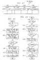
- the message packet 400 sent from the source PC 302 to ARS 308 via Path “A”comprises several fields.
- One fieldcomprises the URL of the ARS 308 which indicates where the message packet is to be sent.
- Another fieldcomprises the advertiser product code or other information derived from the audio signal 11 , and any additional overhead information required for a given transaction.
- the product codeprovides a link to the address of the advertiser server 312 , located in the database 310 .
- Yet another fieldcomprises the network address of the source PC 302 .
- network transmissionsare effected in packets of information, each packet providing a destination address, a source address, and data. These packets vary depending upon the network transmission protocol utilized for communication.
- messages packetshall refer to and comprise the destination URL, product information, and source address, even though more than a single packet must be transmitted to effect such a transmission.
- ARS 308Upon receipt of the message packet 400 from source PC 302 , ARS 308 processes the information in accordance with instructions embedded in the overhead information. The ARS 308 specifically will extract the product code information from the received packet 400 and, once extracted, will then decode this product code information. Once decoded, this information is then compared with data contained within the ARS advertiser database 310 to determine if there is a “hit.” If there is no “hit” indicating a match, then information is returned to the browser indicating such. If there is a “hit,” a packet 402 is assembled which comprises the address of the source PC 302 , and information instructing the source PC 302 as to how to access, directly in a “handoff” operation, another location on the network, that of an advertiser server 312 .
- the source PC 302can then access the advertiser server 312 .
- the ARS 308transmits the packet 402 back to source PC 302 over Path “B.”
- the message packet 402comprises the address of the source PC 302 , the URL of the advertiser server 312 embedded within instructional code, and the URL of the ARS 308 .
- the message packet 402Upon receipt of the message packet 402 by the source PC 302 , the message packet 402 is disassembled to obtain pertinent routing information for assembly of a new message packet 404 .
- the web browser running on source PC 302is now directed to obtain, over Path “C,” the product information relevant to the particular advertiser server 312 location information embedded in message packet 404 .
- the message packet 404 for this transactioncomprises the URL of the advertiser server 312 , the request-for-product-information data, and the address of the source PC 302 .
- advertiser server 312Upon receipt of the message packet 404 from source PC 302 , advertiser server 312 disassembles the message packet 404 to obtain the request-for-product-information data. The advertiser server 312 then retrieves the particular product information from its database, and transmits it over Path “D” back to the source PC 302 . Referring now to FIG. 4 d , the message packet 406 for this particular transaction comprises the address of the source PC 302 , the requested information, and the URL of the advertiser server 312 .
- the ARS 308may make a direct request for product information over Path “E” to advertiser server 312 .
- the ARS 308sends information to the advertiser server 312 instructing it to contact the source PC 302 .
- the message packet 408 for this transactionis illustrated in FIG. 4 e , which comprises the URL of the advertiser server 312 , the request-for-product-information data, and the address of the source PC 302 . Since product information is not being returned to the ARS 308 , but directly to the source PC 302 , the message packet 408 requires the return address to be that of the source PC 302 . The product information is then passed directly to PC 302 over Path “D.”
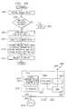
- a proprietary applicationrunning resident on a source computer PC 302 (similar to PC 204 ) monitors the audio input for a special trigger signal.
- data following the trigger signalis decoded for further processing, in function block 502 .
- the datais buffered for further manipulation.
- decision block 506a determination is made as to whether the data can be properly authenticated. If not, program flow continues through the “N” signal to function block 520 where the data is discarded.
- the programthen signals for a retransmission of the data.
- the systemthen waits for the next trigger signal, in decision block 500 . If properly authenticated in decision block 506 , program flow continues through the “Y” signal path where the data is then used to launch the web browser application, as indicated in function block 508 .
- the web browserreceives the URL data, which is then automatically routed through the computer modem 208 to the network interface 304 and ultimately to the network 306 .
- the ARS 308responds by returning the URL of advertiser server 312 to the PC 302 .
- the web browser running on the source PC 302receives the advertiser URL information from the ARS 308 , and transmits the URL for the product file to the advertiser server 312 .
- the advertiser server 312responds by sending the product information to the source PC 302 for processing.
- the usermay obtain the benefits of this architecture by simply downloading the proprietary software over the network.
- Other methods for obtaining the softwareare well-known; for example, by CD, diskette, or pre-loaded hard drives.
- the ARS 308may undergo when receiving the message packet 400 from the source PC 302 .
- decision block 600the ARS 308 checks for the receipt of the message packet 400 . If a message packet 400 is not received, program flow moves along the “N” path to continue waiting for the message. If the message-packet 400 is received, program flow continues along path “Y” for message processing.
- the ARS 308decodes the message packet 400 . The product code is then extracted independently in function block 604 in preparation for matching the product code with the appropriate advertiser server address located in the database 310 .
- function block 606the product code is then used with a lookup table to retrieve the advertiser server 312 URL of the respective product information contained in the audio signal data.
- the ARS 308then assembles message packet 402 for transmission back to the source PC 302 .
- Function block 610indicates the process of sending the message packet 402 back to the source PC 302 over Path “B.”
- the source PC 302receives the message packet 402 back from the ARS 308 and begins to decode the packet 402 .
- the URL of the advertiser product informationis extracted from the message packet 402 and saved for insertion into the message packet 404 to the advertiser server 312 .
- the message packet 404is then assembled and sent by the source PC 302 over Path “C” to the advertiser server 312 , in function block 704 .
- the advertiser server 312receives the message packet 404 from the source PC 302 , in function block 708 , and disassembles it.
- the product information locationis then extracted from the message packet 404 in function block 710 .
- the particular product informationis retrieved from the advertiser server 312 database for transmission back to the source PC 302 .
- the product informationis assembled into message packet 406 and then transmitted back to the source PC 302 over Path “D.”
- the advertiser product information contained in the message packet 406 received from the advertiser server 312is then extracted and processed in function block 716 .
- a web browser application on a source PC 302is automatically launched and computer display 800 presents a browser page 802 .
- Proprietary software running on the source PC 302processes the audio signal data after being digitized through the sound card 206 .
- the softwareappropriately prepares the data for insertion directly into the web browser by extracting the product information code and appending keystroke data to this information.
- a URL page 804is opened in response to a Ctrl-O command added by the proprietary software as the first character string. Opening URL page 804 automatically positions the cursor in a field 806 where additional keystroke data following the Ctrl-O command will be inserted.
- the hypertext protocol preamble http://is inserted into the field 806 .
- URL information associated with the location of the ARS 308is inserted into field 806 .
- URL dataare the characters /? to allow entry of variables immediately following the /? characters.
- the variable followingis the product information code received in the audio signal.
- the product code informationalso provides the cross-reference information for obtaining the advertiser URL from the ARS database 310 .
- a carriage returnis added to send the URL/product data and close the window 804 .
- the message packet 400After the message packet 400 is transmitted to the ARS 308 from the source PC 302 , transactions from the ARS 308 , to the source PC 302 , to the advertiser server 312 , and back to the source PC 302 , occur quickly and are transparent to the viewer. At this point, the next information the viewer sees is the product information which was received from the advertiser server 312 .
- a video source 902is provided which is operable to provide an audio output on an audio cable 901 which provides routing information referred to by reference numeral 904 .
- the routing information 904is basically information contained within the audio signal. This is an encoded or embedded signal. The important aspect of the routing information 904 is that it is automatically output in realtime as a function of the broadcast of the video program received over the video source 902 . Therefore, whenever the program is being broadcast in realtime to the user 908 , the routing information 904 will be output whenever the producer of the video desires it to be produced.
- the box 902 representing the video sourcecould be any type of media that will result in the routing information being output. This could be a cassette player, a DVD player, an audio cassette, a CD ROM or any such media. It is only important that this is a program that the producer develops which the user 908 watches in a continuous or a streaming manner. Embedded within that program, at a desired point selected by the producer, the routing information 904 is output.
- the audio informationis then routed to a PC 906 , which is similar to the PC 112 in FIG. 1.
- a user 908is interfaced with the PC to receive information thereof, the PC 906 having associated therewith a display (not shown).
- the PC 906is interfaced with a network 910 , similar to the network 306 in FIG. 3 .
- This network 910has multiple nodes thereon, one of which is the PC 906 , and another of which is represented by a network node 912 which represents remote information.
- the object of the present embodimentis to access remote information for display to the user 908 by the act of transmitting from the video program in block 902 the routing information 904 .
- This routing information 904is utilized to allow the PC 906 which has a network “browser” running thereon to “fetch” the remote information at the node 912 over the network 910 for display to the user 908 .
- This routing information 904is in the form of an embedded code within the audio signal, as was described hereinabove.
- the PC 906is split up into a couple of nodes, a first PC 1002 and a second PC 1004 .
- the PC 1002resides at the node associated with the user 908
- the PC 1004resides at another node.
- the PC 1004represents the ARS 308 of FIG. 3 .
- the PC 1004has a database 1006 associated therewith, which is basically the advertiser database 310 . Therefore, there are three nodes on the network 910 necessary to implement the disclosed embodiment, the PC 1002 , the PC 1004 and the remote information node 912 .
- the routing information 904is utilized by the PC 1002 for routing to the PC 1004 to determine the location of the remote information node 912 on the network 910 . This is returned to the PC 1002 and a connection made directly with the remote information node 912 and the information retrieved therefrom to the user 908 .
- the routing information 904basically constitutes primary routing information.
- FIG. 11there is illustrated a diagrammatic view of how the network packet is formed for sending the primary routing information to the PC 1004 .
- the primary routing informationoccupies a single field which primary routing information is then assembled into a data packet with the secondary routing information for transfer to the network 910 . This is described hereinabove in detail.
- the video source 902has associated therewith an optical region 1202 , which optical region 1202 has disposed therein an embedded video code.
- This embedded video codecould be relatively complex or as simple as a grid of dark and white regions, each region in the grid able to have a dark color for a logic “1” or a white region for a logic “0.” This will allow a digital value to be disposed within the optical region 1202 .
- a sensor 1204can then be provided for sensing this vide code. In the example above, this would merely require an array of optical detectors, one for each region in the grid to determine whether this is a logic “1” or a logic “0” state.
- One of the sensed videois then output to the PC 906 for processing thereof to determine the information contained therein, which information contained therein constitutes the primary routing information 904 . Thereafter, it is processed as described hereinabove with reference to FIG. 9 .
- the PC 906has associated therewith a profile database 1302 , which profile database 1302 is operable to store a profile of the user 908 .
- This profileis created when the program, after initial installation, requests profile information to be input in order to activate the program.
- a unique IDthat is provided to the user 908 in association with the browser program that runs on the PC 906 .
- Thisis stored in a storage location represented by a block 1304 .
- This ID 1304is accessible by a remote location as a “cookie” which is information that is stored in the PC 906 in an accessible location, which accessible location is actually accessible by the remote program running on a, remote-node.
- the ARS 308which basically constitutes the PC 1004 of FIG. 10 , is operable to have associated therewith a profile database 1308 , which profile database 1308 is operable to store profiles for all of the users.
- the profile database 1308is a combination of the stored in profile database 1302 for all of the PC 906 that are attachable to the system. This is to be distinguished from information stored in the database 310 of the ARS 308 , the advertiser's database, which contains intermediate destination tables.
- the routing information in the primary routing information 904is forwarded to the ARS 308 and extracted from the original data packet, the lookup procedure descried hereinabove can then be performed to determines where this information is to be routed.
- the profile database 1302is then utilized for each transaction, wherein each transaction in the form of the routing information received form the primary routing information 904 is compared to the destination tables of database 310 to determine what manufacturer is associated therewith.
- the associated ID 1304 that is transmitted along with the routing information primary routing information 904is then compared with the profile database 1308 to determine if a profile associated therewith is available.
- This informationis stored in a transaction database 1310 such that, at a later time, for each routing code received in the form of the information in primary routing information 904 , there will associated therewith the IDs 1304 of each of the PCS 906 .
- the associated profiles in database 1308which are stored in association with IDs 1304 , can then be assembled and transmitted to a subscriber as referenced by a subscriber node 1312 on the network 910 .
- the ARS 308can do this in two modes, a realtime mode or a non-realtime mode.
- a PC 906accesses the advertiser database 310 , that user's profile information is uploaded to the subscriber node 1312 .
- billing informationis generated for that subscriber 1312 which is stored in a billing database 1316 . Therefore, the ARS 308 has the ability to inform the subscriber 1312 of each transaction, bill for those transactions, and also provide to the subscriber 1312 profile information regarding who is accessing the particular product advertisement having associated therewith the routing information field 904 for a particular routing code as described hereinabove. This information, once assembled, can then be transmitted to the subscriber 1312 and also be reflected in billing information and stored in the billing information database 1316 .
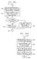
- FIG. 14there is illustrated a flowchart depicting the operation for storing the profile for the user.
- the programis initiated in a block 1402 and then proceeds to a function block 1404 , wherein the system will prompt for the profile upon initiation of the system.
- This initiationis a function that is set to activate whenever the user initially loads the software that he or she is provided. The purpose for this is to create, in addition to the setup information, a user profile.
- the programwill flow to a decision block 1406 to determine whether the user provides basic or detailed information. This is selectable by the user. If selecting basic, the program will flow to a function block 1408 wherein the user will enter basic information such as name and serial number and possibly ar address.
- the original prompt in function block 1404would have offers for such things as coupons, discounts, etc., if the user will enter additional information. If the user selects this option, the program flows from the decision block 1406 to a function block 1410 . In the function block 1410 , the user is prompted to enter specific information such as job, income level, general family history, demographic information and more. There can be any amount of information collected in this particular function block.
- the programwill then flow to a function block 1412 where this information is stored locally.
- the programthen flows to a decision block 1414 to then go on-line to the host or the ARS 308 .
- the useris prompted to determine whether he or she wants to send this information to the host at the present time or to send it later. If he or she selects the “later” option, the program will flow to a function block 1415 to prompt the user at a later time to send the information.
- the userwill not be able to utilize the software until the profile information is sent to the host. Therefore, the user may have to activate this at a later time in order to connect with the host.
- the programwill flow to the function block 1416 to initiate the connect process and then to a decision block 1418 to determine if the connection has been made. If not, the program will flow along a “N” path to a time to decision block 1420 which will timeout to an error block 1422 or back to the input of the connect decision block 1418 . The program, once connected, will then flow along a “Y” path from decision block 1418 to a function block 1428 to send the profile information with the ID of the computer or user to the host.
- the IDis basically, as described hereinabove, a “cookie” in the computer which is accessed by the program when transmitting to the host.
- the programwill then flow to a function block 1430 to activate the program such that it, at later time, can operate without requiring all of the setup information. In general, all of the operation of this flowchart is performed with a “wizard” which steps the user through the setup process. Once complete, the program will flow to a Done block 1432 .
- FIG. 15there is illustrated a flowchart depicting the operation of the host when receiving a transaction.
- the programis initiated at a Start block 1502 and then proceeds to decision block 1504 , wherein it is determined whether the system has received a routing request, i.e., the routing information 904 in the form of a tone, etc., embedded in the audio signal, as described hereinabove with respect to FIG. 9 .
- the programwill loop back around to the input of decision block 1504 until the routing request has been received.
- the programwill flow along the “Y” path to a function block 1506 to receive the primary routing information and the user ID. Essentially, this primary routing information is extracted from the audio tone, in addition to the user ID.
- the programthen flows to a function block 1508 to look up the manufacturer URL that corresponds to the received primary routing information and then return the necessary command information to the originating PC 108 in order to allow that PC 108 to connect to the destination associated with the primary routing information. Thereafter, the program will flow to a function block 1510 to update the transaction database 1310 for the current transaction.
- the routing information 904will be stored as a single field with the associated IDs.
- the profile database 1308has associated therewith detailed profiles of each user on the system that has activated their software in association with their ID. Since the ID was sent in association with the routing information, what is stored in the transaction database 1310 is the routing code, in association with all of the IDs transmitted to the system in association with that particular routing code. Once this transaction datable 1310 has been updated, as described hereinabove, the transactions can be transferred back to the subscriber at node 312 with the detailed profile information from the profile database 1308 .
- the profile informationcan be transmitted back to the subscriber or manufacturer at the node 312 in realtime or non-realtime.
- a decision block 1512is provided for this, which determines if the delivery is realtime. If realtime, the program will flow along a “Y” path to a function block 1514 wherein the information will be immediately forwarded to the manufacturer or subscriber. The program will then flow to a function block 1516 wherein the billing for that particular manufacturer or subscriber will be updated in the billing database 1316 . The program will then flow into an End block 1518 . If it was non-realtime, the program moves along the “N” path to a function block 1520 wherein it is set for a later delivery and it is accrued in the transaction database 1310 . In any event, the transaction database 1310 will accrue all information associated with a particular routing code.
- a cola manufacturerwere to provide a promotional advertisement on, for example, television, indicating that a new cola was going to be placed on the shelf and that the first 1000 purchasers, for example, scanning their code into the network would receive some benefit, such as a chance to win a trip to some famous resort in Florida or some other incentive, the manufacturer would have a very good idea as to how well the advertisement was received. Further, the advertiser would know where the receptive markets were. If this advertiser, for example, had placed the television advertisement in ten cities and received overwhelming response from one city, but very poor response from another city, he would then have some inclination to believe that either the one poor-response city was not a good market or that the advertising medium he had chosen was very poor. Since the advertiser can obtain a relatively instant response and also content with that response as to the demographics of the responder, very important information can be obtained in a relatively short time.
- the disclosed embodimentis not limited to a single source PC 302 , but may encompass a large number of source computers connected over a global communication network. Additionally, the embodiment is not limited to a single ARS 308 or a single advertiser server 312 , but may include a plurality of ARS and advertiser systems, indicated by the addition of ARS 314 and advertiser server A 316 , respectively. It should also be noted that this embodiment is not limited only to global communication networks, but also may be used with LAN, WAN, and peer-to-peer configurations.
- the disclosed embodimentis not limited to a personal computer, but is also applicable to, for example, a Network Computer (“NetPC”), a scaled-down version of the PC, or any system which accommodates user interaction and interfaces to information resources.
- Network Computera Network Computer
- One typical application of the above noted techniqueis for providing a triggering event during a program, such as a sport event. In a first example, this may be generated by an advertiser.
- an advertisercontracted for 15 seconds worth of advertising time, they could insert within their program a tone containing the routing information.
- This routing informationcan then be output to the user's PC 302 which will cause the user's PC 302 to, via the network, obtain information from a remote location typically controlled by the advertiser.
- An important aspect to the type of interaction between the actual broadcast program with the embedded routing information and the manufacturer's siteis the fact that there is provided information as to the user's PC 302 and a profile of the user themselves. Therefore, an advertiser can actually gain realtime information as to the number of individuals that are watching their particular advertisement and also information as to the background of those individuals, profile information, etc. This can be a very valuable asset to an advertiser.
- the producer of the programcan allow the user to automatically access additional information that is not displayed on the screen.
- additional informationFor example, in a sporting event, various statistics can be provided to the user from a remote location, merely by the viewer watching the program. When these statistics are provided, the advertiser can be provided with profile information and background information regarding the user. This can be important when, for example, the user may record a sports program. If the manufacturer sees that this program routing code is being output from some device at a time later than the actual broadcast itself, this allows the advertisers to actually see that their program is still being used and also what type of individual is using it.
- the broadcastercould determine the same and actually bill the advertiser an additional sum for a later broadcast. This is all due to the fact that the routing information automatically, through a PC and a network, will provide an indication to the advertiser the time at which the actual information was broadcast.
- the different type of medium that can be utilized with the above embodimentare such things as advertisements, which are discussed hereinabove, contests, games, news programs, education, coupon promotional programs, demonstration media (demos), and photographs, all of which can be broadcast on a private site or a public site. This all will provide the ability to allow realtime interface with the network and the remote location for obtaining the routed information and also allow for realtime billing and accounting.
- a bar code scanning input device 1600is provided by a input device distributor to customers and is associated with that distributor via a input device ID stored therein.
- the input device 1600is either sold or freely distributed to customers for use with their personal computing systems. Since more and more products are being sold using bar codes, it can be appreciated that a user having the input device 1600 can scan bar codes of a multitude of products in order to obtain more information. Information about these products can be made immediately available to the user from the manufacturer for presentation by the user's computer 302 . Beyond simply displaying information about the product in which the user is interested, the input device distributor may include additional advertising information for display to the user such as information about other promotions or products provided or sold by the input device distributor.
- advertisersmay provide catalogs of advertisements or information in newspapers or periodicals where the user simply scans the bar code associated with the advertisement using the input device 1600 to obtain further information.
- a paper source 1602having contained thereon an advertisement 1604 and an associated bar code 1606 .
- the disclosed conceptis not limited to scanning of bar codes 1606 from paper sources 1602 , but is also operable to scan a bar code 1606 on the product itself.
- the input device 1600can be any type of device that will scan any type of image having information encoded therein.
- the userAfter obtaining the input device 1600 from the input device distributor, the user connects the input device 1600 to their PC 302 .
- input device 1600reads bar code data 1606 and the input device ID into a “wedge” interface 1608 for conversion into keyboard data, which keyboard data is passed therefrom into the keyboard input port of PC 302 .
- the importance of the input device IDwill be discussed in more detail hereinbelow.
- the wedge interface 1608is simply an interface box containing circuitry that accommodates inputs from both the scanning input device 1600 and a computer keyboard 1610 . This merely allows the information scanned by the input device 1600 to be input into the PC 302 . In the disclosed embodiment, the wedge interface 1608 will convert any information. The data output from the input device 1600 is passed into the wedge interface 1608 for conversion into keyboard data which is readily recognizable by the PC 302 . Therefore, the input device 1600 is not required to be connected to a separate port on the PC 302 . This data is recognized as a sequence of keystrokes. However, the output of the input device 1600 can be input in any manner compatible with the PC 302 .
- the wedge interface 1608When not receiving scanner data, the wedge interface 1608 simply acts as a pass-through device for keyboard data from the keyboard 1610 . In any case, the information is ultimately processed by a processor in the PC 302 and can be presented to the user on a display 1612 .
- the wedge interface 1608is operable to provide a decoding function for the bar code 1606 and conversion thereof to keystroke input data.
- the product code of a productis provided in the form of a bar code 1606 .
- This bar code 1606is the “link” to a product.
- the disclosed embodimentis operable to connect that product information contained in the bar code 1606 with a web page of the manufacturer of that product by utilizing the bar code 1606 as the product “identifier.”
- the program operating on the PC 302provides routing information to the ARS 308 after launching the browser on the PC 302 and connecting to the ARS 308 over the GCN 306 , which ARS 308 then performs the necessary steps to cause the browser to connect to the manufacturer web site, while also providing for an accounting step, as will be described in more detail hereinbelow.
- the bar code 1606by itself is incompatible with any kind of network for the purposes of communication therewith. It is primarily provided for a retail-type setting. Therefore, the information contained in the bar code 1606 , by itself, does not allow for anything other than identification of a product, assuming that one has a database 1614 containing information as to a correlation between the product and the bar code 1606 .
- the wedge interface 1608is operable to decode the bar code 1606 to extract the encoded information therein, and append to that decoded bar code information relating to an ID for the input device 1600 . This information is then forwarded to the ARS 308 by the resident program in the PC 302 . This is facilitated by intermediate routing information stored in the program indicating to which node on the GCN 306 the scanned bar code information is to be sent, i.e., to the ARS 308 . It is important to note that the information in the bar code 1606 must be converted from its optical image to numerical values which are then ultimately input to the keyboard input port of PC 302 and converted into data compatible with communication software residing on the PC 302 (in this case, HTML language for insertion into a browser program).
- the resident programlaunches the browser program and then assembles a communication packet comprised of the URL of the ARS 308 , the input device ID and the user ID. If another type of communications program were utilized, then it would have to be converted into language compatible with that program. Of course, a user could actually key in the information on the bar code 102 and then append the appropriate intermediate routing information thereafter. As will be described hereinbelow, the intermediate routing information appended thereto is the URL of the ARS 308 disposed on the GCN 306 .
- the PC 302hosts input device software which is operable to interpret data transmitted from the input device 1600 , and to create a message packet having the scanned product information and input device ID, routing information, and a user ID which identifies the user location of the input device 1600 .
- the input device softwareloads at boot-up of the PC 302 and runs in the background.
- the wedge interface 1608outputs a keystroke code (e.g., ALT-F10) to bring the input device program into the foreground for interaction by the operating system.
- the input device programthen inserts the necessary information into the browser program.
- the message packetis then transmitted to interface 304 across the global communication network 306 to the ARS 308 .
- the ARS 308interrogates the message packet and performs a lookup function using the ARS database 310 . If a match is found between particular parameters of the message packet, a return message packet is sent back to the PC 302 for processing.
- the input device program running on PC 302functions to partition the browser window displayed to the user into several individual areas. This is for the purpose of preparing to present to the user selected information in each of the individual areas (also called “framing”).
- the selected informationcomprises the product information which the user requested by scanning the bar code 1606 using the input device 1600 , information about the input device distributor which establishes the identity of the company associated with that particular input device 1600 , and at least one or more other frames which may be advertisements related to other products that the input device distributor sells. Note that the advertisements displayed by the input device distributor may be related to the product of interest or totally unrelated.
- the input device distributormay generate an advertisement of a new soft drink being marketed by Company A, that it sells.
- the input device distributormay also structure the display of information to the user such that a user requesting product information of a Product X may get the requested information of Product X along with advertisements for a competing item Product Y. Essentially, the input device distributor is free to generate any advertisement to the user in response to the user requesting product information.
- the return message packet transmitted from the ARS 308 to the PC 302is then transmitted back across the GCN 306 to the advertiser server 312 .
- the advertiser server 312restructures the message packet and appends the particular product information for transmission back to the PC 302 .
- the PC 302Upon receiving the particular advertiser information from advertiser server 312 , the PC 302 then retransmits a message to the input device distributor site 1616 and E-commerce site 1618 to obtain the information that needs to be framed in the browser window displayed to the user.
- the input device 1600is associated with the input device distributor by way of a input device ID such that scanning a product bar code 1606 in order to obtain information about that particular product generates one or more responses from one or more remote sites disposed on the GCN 306 .
- the input device IDStored in the input device 1600 is the input device ID which establishes its relationship to the input device distributor.
- Proprietary input device softwarerunning on the PC 302 operates to decode scanned bar code information and the input device ID received from the input device 1600 and wedge interface 1608 , and also provides a unique user ID for establishing the location of the user of the input device 1600 .
- the input device softwarealso assembles message packets and works in conjunction with the on-board communication software (e.g., a browser) to automatic ally route the message packets across the GCN 306 such that the one or more remote sites disposed on the GCN 306 return information to be framed for presentation to the user.
- the on-board communication softwaree.g., a browser
- a microcontroller 1700provides conversion of the data from the input device 1600 and controls interfacing of the keyboard 1610 and input device 1600 with the PC 302 .
- the microcontroller 1700has contained therein a memory 1702 or it can have external memory.
- the input device interfaces 1704comprise a serial data line, a ground line, and a power line.
- the keyboard interfaces 1708comprise a serial data line, a ground line, a clock line, and a power line.
- the PC 302provides a clock line, a power line, a serial data, and a ground line for input to the microcontroller 1700 .
- the microcontroller 1700is operable to receive signals from the keyboard 1610 and transfer the signals to the PC 302 as keyboard signals. Operation with the keyboard 1610 is essentially a “pass-through” procedure. Data output from the keyboard 1610 is already in keyboard format, and therefore requires no conversion by the wedge interface 1608 . With respect to the input device 1600 , the serial data is not compatible with a keyboard 1610 and, therefore, it must be converted into a keyboard format in order to allow input thereof to the keyboard input of the PC 302 .
- the microcontroller 1700performs this function after decoding this bar code information, and conversion of this bar code information into an appropriate stream of data which is comprised of the bar code information and the appended URL.
- This appended URLwill be pre-stored in the memory 1702 and is programmable at the time of manufacture.
- the memory 1702is illustrated as being contained within the microcontroller 1702 to provide a single chip solution. However, this could be external memory that is accessible by the microcontroller 1702 . Therefore, the microcontroller 1700 provides an interface between the input device 1600 and the keyboard 1610 to the PC 302 which allows the input device 1600 to receive coded information and convert it to keyboard strokes or, alternatively, to merely pass-through the keystrokes from the keyboard 1610 . Therefore, the user need not install any type of plug-in circuit board into the motherboard of the PC 302 in order to provide an interface to the input device 1600 ; rather, the user need only utilize the already available keyboard port in order to input the appropriate data into the system.
- the microcontroller 1700comprises a PIC16C73 microcontroller by Microchip TechnologiesTM.
- the PIC16C73 deviceis a low cost CMOS 8-bit microcontroller with an integrated analog-to-digital converter.
- the PIC16C73 deviceas illustrated in the disclosed embodiment, has 192 bytes of RAM and 4k ⁇ 4 of EPROM memory.
- the microcontroller 1700can accommodate asynchronous or synchronous inputs from input devices connected to it. In this disclosed embodiment, communication to the keyboard 1610 is synchronous while it is asynchronous when communicating with input device 1600 .
- bar code information of the bar code 1606is input into the keyboard input port of the PC 302 , disclosed methods may also be advantageously utilized with high speed port architectures such as Universal Serial Bus (“USB”) and IEEE 1394.
- USBUniversal Serial Bus
- IEEE 1394IEEE 1394
- Bar codesare structured to be read in either direction. Timing considerations need to be addressed because of the variety of individuals scanning the bar code introduce a wide variety of scan rates. Bar codes use bars of varying widths. The presence of a black bar generates a positive pulse, and the absence of a black bar generates no pulse. Each character of a conventional bar code has associated therewith seven pulses or bars. Depending on the width of the bars, the time between pulses varies. In this disclosed embodiment, the interface circuitry 1608 performs a “running” calculation of the scan time based upon the rising edge of the pulses commencing with the leader or header information. The minimum and maximum scans times are calculated continuously in software with the interface 1608 during the scanning process to ensure a successful scan by the user.
- the message packet 1800comprises a number of bits of information including the bar code information 1802 obtained from the user scanning the bar code 1606 with the input device 1600 ; the input device ID 1804 which is embedded in a memory in the input device 1600 and identifies it with a particular input device distributor; and a user ID 1806 which is derived from the software running on the PC 302 and which identifies uniquely with the user location.
- the message packetincludes other necessary information for the proper transmission for point to point.
- FIG. 19there is illustrated a more detailed block diagram of the routing of the message packets in order to present the framed information to the user.
- a input device programrunning on the user PC 302 is operable to interpret the information output by the input device 1600 and generate a message packet for transmission over the GCN 306 .
- the input device programassembles the message packet such that it is directed to the ARS 308 disposed on the GCN 306 .
- the message packetcontains several pieces of information including the input device ID 1804 which links it to the input device distributor, the user ID 1806 which identifies the particular user using the input device 1600 , and bar code information 1802 describing a particular product of interest to the user.
- This message from the PC 302is transmitted over a path 1900 to the ARS 308 where the ARS database 310 is accessed to cross reference the ID information 1804 and bar code information 1802 to a particular advertiser and input device distributor.
- the ARS 308returns a message packet over a path 1902 to the user PC 302 which contains routing information as to the location of various other sites disposed on the GCN 306 , for example, the advertiser server 312 and input device distributor site 1616 .
- the ARS 308can also be provided by the ARS 308 which more closely targets the particular user of the input device 1600 . For example, if it is known that a particular input device 1600 is sold in a certain geographic area, this information can be useful in targeting the particular user with certain advertising information relevant to that geographic area.
- the information returned from the ARS 308 over path 1902provides enough information for the input device program running on the user PC 302 to identify a number of other sites disposed on the GCN 306 .
- the user PC 302then processes the return message packet and routes another message packet over a path 1904 to the advertiser server 312 .
- the advertiser server 312then returns product information of the particular product in which the user was interested back to the user PC 302 over a path 1906 .
- the user PC 302routes information (e.g., the URL of the input device distributor site and the user profile) to the input device distributor site 1616 over a path 1908 in order to obtain information back over a path 1910 for framing any banners which identify the input device distributor. Additionally, the user PC 302 forwards a message packet to the E-commerce site 1618 over a path 1912 in order to return information regarding any particular advertisements the input device distributor wants to display to the user. The advertisements are returned to the PC 302 over a path 1914 .
- informatione.g., the URL of the input device distributor site and the user profile
- FIG. 20there is illustrated a block diagram of a browser window according to the disclosed embodiment.
- the browser window 200partitioned into a plurality of areas for framing specific information.
- a bar code area 2002displays that product information which the user was interested
- an input device-specific area 2004displays information about the input device distributor
- an E-commerce area 2006displays advertising information that the input device distributor selects for display according to this particular user and input device 1600 .
- a program operable to process scanned bar code information with the unique input device 1600develops the browser window by partitioning it into specific areas for the framing of information. Therefore, information returned from the E-commerce site 1608 is passed through the GCN 306 to the particular E-commerce frame 2006 .
- information about the particular product of interestis returned from the advertiser site 312 across the GCN 306 to the particular bar code specific area 2002 .
- Information placed in the input, device specific area 2004is information about the input device distributor which is returned from the input device distributor site 1616 across GCN 306 .
- the ARS database 310contains a variety of information required to properly interrogate and assemble packets for obtaining information from the various sites disposed on the GCN 306 .
- the ARS database 310has a database structure 2100 which contains addresses for the web sites containing the product information requested by the user when scanning the bar code 1606 with the input device 1600 . Under a PRODUCT heading 2102 are listed the particular bar codes and associated routing information for addressing the respective server location.
- the ARS server 308may contain any number of advertisers having unique URL addresses associated therewith.
- the bar code 1606 of a particular productis associated with a unique URL address which routes any request for information of that product to that particular advertiser's site. Also part of the ARS database structure 2000 is a heading of INPUT DEVICE under which is the input device ID 1804 and the distributor associated with that input device ID 1804 .
- each distributorhas an ID embedded in the input device 1600 which uniquely identifies that input device with the particular distributor. Therefore, the unique input device ID 1804 needs to be listed with the respective distributors of that input device 1600 in order to process the information that needs to be framed and displayed to that particular user.
- Another heading under the ARS database structure 2100is a user heading 2106 which contains profile information associated with that particular user ID 1806 .
- the user ID 1806is obtained via the input device software running oh the PC 302 and upon installation or subsequent configuration may request that the user input certain profile information which may be used to target that particular user with products and services which identify with that user profile.
- the ARS database structure 2100also contains an E-commerce heading 2108 which contains information related to the bar code 1606 and an advertisement that may be triggered by the request for that information.
- E-commerce heading 2108contains information related to the bar code 1606 and an advertisement that may be triggered by the request for that information.
- any bar code 1606 associated with a paper source 1602can be associated with the specific information in the ARS database 310 .
- a user wishing to obtain information about a specific soft drinkmay, in fact, trigger an advertising response of a competitor product.
- the user interested in information about that particular soft drinkmay also trigger information which is relevant to that particular product or a product which may normally be served in conjunction with that soft drink.
- the request for information regarding this particular bar coded productmay trigger advertisement from an E-commerce server 1618 related to information about finance and insurance.
- the information described as contained within the ARS database structure 2100is not limited to what has been described, but may comprise any number of pieces of information used to present desired information to the computer display of the user.
- FIG. 22there is illustrated a flowchart of the process of receiving information from the user's perspective, and according to the disclosed embodiment.
- the input device software running on the user's PC 302runs in the background until activated by output from the input device 1600 . Therefore, flow moves to a decision block 2200 where if a scanned input does not occur, flow moves out the “N” path and loops back to the input of decision block 2200 . On the other hand, if scanned input information is received, flow moves out the “Y” path to a function block 2202 where the input device software assembles a message packet containing the bar code information, the input device ID 1804 and the ARS 308 URL address.
- the browseris launched in which this information is placed for transmission to the ARS 308 .
- Flowthen moves to a function block 2204 where the browser is partitioned into any number of areas which information is displayed when obtained from the input device distributor site 1616 , the E-commerce site 1618 , and the advertiser server 312 . It should be known that although three frames are shown in the particular window 2000 of this embodiment, the number of frames displayed in the window 2000 is limited only by the available real estate of the window 2000 area itself.
- Flowis then to a function block 2212 where the proprietary software working in conjunction with the hosted browser places the returned information into the respective frames of the window.
- the userviewing the display at PC 302 , then perceives a variety of information, one of which is the particular product information which he or she requested, in addition to input device distributor information, and possibly other advertisements based upon the user's profile.
- the ARS 308is operable to decode and process messages received from the GCN 306 . Therefore, flow is to a decision block 2300 where, if bar code information is not received, flow is out the “N” path with loop-back to its input. If bar code information has been received, flow is to a function block 2302 where a matching process occurs to link the bar-coded product information to its respective manufacturer.
- the ARS database 310also associates the URL address of the manufacturer's server. When a match is found, the ARS 308 begins to assemble a message packet of information for transmission back to the PC 302 , as indicated in function block 2304 .
- the message packetcontains the product information and the URL address of the manufacturer's website.
- Flowthen moves to a decision block 2306 where the input device ID 1804 is compared with the list of input device IDs issued by the particular input device distributor. If the input device ID 1804 is validated, flow moves out the “Y” path to a function block 2308 where the message packet is appended with the input device ID 1804 and distributor routing address.
- Flowthen moves to a decision block 2310 where the ARS 308 determines if any E-commerce information is to be associated with a particular input device ID 1804 . If so, flow is out the “Y” path to a function block 2312 where the message packet is appended with the E-commerce routing string.
- the E-commerce routing stringprovides addressing for the E-commerce server 1618 .
- Flowthen moves to a function block 2314 where all message packets are returned back to the PC 302 for processing.
- the E-commerce server 1618receives the message packet from the user PC 302 , as indicated in function block 2400 , and decodes the packet to perform a match with the bar coded information. Moving on to a decision block 2402 , if the match is unsuccessful, flow is out the “N” path to a function block 2404 where the match is rejected. A message may be returned to indicate that a problem occurred and the user may need to re-scan the product bar code 1606 . If a successful match occurs, flow moves out the “Y” path to a function block 2406 where the input device ID 1804 is matched with the bar code product information.
- the bar coded informationmay be distributed to customers over a large geographic area.
- the input device 1606may be coded for certain geographic areas.
- a input device 1600 having an XXX IDmay be restricted for sale in the Southwestern United States while a input device 1600 having a YYY ID may be sold only in the Northeast.
- geographic areasmay be targeted with advertising more appealing to that particular area.
- Advertising returned to the user PC 302may be focused further by obtaining a user profile when the software or input device 1600 are installed. In this way, advertising may be focused based upon the user profile. Therefore, flow moves to a function block 2408 to lookup the E-commerce action based upon the input device ID 1804 and the bar code information. Flow moves to a function block 2410 to assemble all the information into a packet for return to the user PC 302 . The product information and/or user profile information may be returned. Flow is then to a function block 2412 where the message packet is transmitted.
- wireless devicesinclude handheld computers (also known as personal digital assistants (“PDAs”)) having integrated wireless Internet access, e.g., the Palm VIIx produced by Palm Inc., cellular telephones having integrated Internet access capabilities, e.g., telephones conforming to the Wireless Application Protocol (WAP) established by the Wireless Application Protocol Forum Ltd., two-way digital pagers and other commercially available devices.
- PDAspersonal digital assistants
- WAPWireless Application Protocol
- All of these wireless devicesincludes a processor and a transmitter/receiver for sending and receiving radio frequency (RF) signals to provide two-way digital communication between the device's processor and a computer network.
- RFradio frequency
- numerous additional componentse.g., memories, displays and input devices, are present in these wireless devices, their specific nature depending upon the type of device and desired features. The general construction of such wireless devices is, however, conventional and thus will not be described in detail.
- FIG. 25there is illustrated a diagrammatic view of one embodiment of a system for connecting a wireless device to a remote location on a computer network.
- the systemincludes a beacon unit 2502 disposed at a geographic location 2504 and transmitting a beacon signal (denoted by arrow 2506 ) into a target region adjacent to the beacon location.
- the systemalso includes a beacon signal receiver circuit (hereafter “BSRC”) 2508 disposed with a wireless device 2510 and operably connected to the processor of the wireless device.
- BSRCbeacon signal receiver circuit
- the BSRC 2508Upon receiving the beacon signal 2506 , the BSRC 2508 sends control signals to the processor of the wireless device 2510 .
- the processor of the wireless device 2510in response to receiving these control signals, instructs the wireless device to connect to a specific remote location on a computer network.
- This connectioncan be completely automatic or it can be made at the option of the user, but in any case it obviates the need for the user to manually input a network address for the remote location.
- the beacon unit 2502is mounted on an outdoor advertising structure (i.e., a billboard) 2522 located adjacent to a roadway 2514 .
- the wireless device 2510is disposed within an automobile 2512 traveling along the roadway 2514 .
- the wireless-device 2510includes a processor and a transmitter/receiver for sending and receiving RF signals (denoted by arrows 2516 ).
- the RF signals 2516provide two-way digital communications with a computer network, in this case GCN 306 , which may be the Internet.
- the RF signals 2516allow communication between the processor of the wireless device 2510 and the computer network 306 through a wireless network interface 2518 , which in this case also serves as an Internet service provider (ISP).
- ISPInternet service provider
- the network interface 2518 in FIG. 25shows only one antenna 2520 ; however, it will be appreciated that the typical wireless network interface comprises a plurality of antennas 2520 and associated radio equipment (not shown) which are distributed across the service area (e.g., in cells) and operably interconnected allowing the wireless device 2510 to maintain virtually unbroken communications with the network 306 as it moves within the service area. It is noted that these wireless devices operate on a delay, such that a request for information may be buffered at the wireless device 2510 in the event of a communication interruption. When communications are resumed, then the request is sent. In the same way, reply information is buffered, such that there may be a delay in returning the information.
- a packet of request informationmay be buffered at the wireless device 2510 until communication is resumed, and then transmitted to the ISP 2518 .
- the ISP 2518acknowledges to the wireless device 2510 that the information has been received.
- the ISP 2518then handles the request outside of the wireless connection over link 2520 .
- this informationis buffered at the ISP 2518 and delivered to the wireless device 2510 when communications permit. Since the primary communication protocol is packet-based in nature, this type of buffering is easily facilitated.
- the beacon unit 2502includes a transmitter 2602 , a modulator 2604 operably connected to the transmitter, and a processor 2606 which is operably connected to the modulator.
- the transmitter 2602transmits the beacon signal 2506 into the target region.
- the information content (i.e., modulation) of the beacon signal 2506is supplied to the transmitter 2602 by the modulator unit 2604 , which in turn receives the content from the processor 2606 .
- the beacon signal 2506may be modulated to carry information content in either digital or analog form.
- the transmitter 2602is a radio frequency (RF) unit for transmitting an RF beacon signal 2506 .
- RFradio frequency
- An antenna 2608is operably connected to the transmitter 2602 to provide desired signal radiation strength and directional properties, thereby controlling the size and shape of the target region.
- Using an omnidirectional antenna 2608will result in a generally circular target region which surrounds the location of the beacon unit 2502 .
- Using a directional antenna 2608will result in a narrower, more focused target region, typically to one side of the beacon unit 2502 .
- the frequency of the RF beacon signal 2506will be different from the frequency used by the wireless device 2510 for network communication signals 2516 , thereby allowing the signals to operate simultaneously without causing interference.
- the beacon unitmay have an optical transmitter for transmitting an optical beacon signal.
- An optical beacon signal 2506may have a carrier wavelength in the visible light portion, the infrared (IR) portion, or the ultraviolet (UV) portion of the electromagnetic spectrum.
- Such optical beacon signalsmay be produced using either non-coherent or coherent (e.g., laser) light sources.
- Optical beacon signals 2506will typically require a line-of-sight path between the beacon 2502 and the BSRC 2508 , however, this may be desirable for certain applications. Further, it avoids RF interference and licensing problems.
- the beacon unit 2502may have an acoustic transmitter for transmitting an acoustic beacon signal.
- the acoustic beacon signal 2506may have a carrier wavelength in the human-perceptible frequency range or within the ultrasonic frequency range. Acoustic beacon signals 2506 will typically be of short range, but a line-of-sight path is not required.
- an electric memory device 2610is operably connected to the processor 2606 .
- the memory device 2610includes one or more memory locations which store data, also known as “codes,” that can be retrieved by the processor 2606 .
- the processor 2606sends signals indicative of the retrieved codes to the modulator 2604 for incorporated as a component of the beacon signal 2506 transmitted by the transmitter 2602 .
- first memory location 2612contains a different code.
- the first code(denoted “MSG. CODE”) in the first memory location 2612 may be associated with a specific remote location on the network 306 to facilitate the connection of the wireless device receiving the code to that specific remote location.
- this associationmay have one of several forms.
- the first code 2612actually includes routing information (e.g., a URL or other network address) associated with a specific remote location on the network. In other words, the routing information is actually “embedded” or “encoded” in the first code 2612 .
- the first code 2612does not actually include routing information to the remote location, but rather is associated with the remote location by other means. This may be by association of the first code 2612 and the remote location in a secondary database such as the advertiser server 312 as further described below.
- the second code (denoted in this example by “LOC. ID”) in the second memory location 2614is also transmitted by the transmitter 2602 as a component of the beacon signal 2506 .
- the second codemay be associated with an attribute of the beacon unit 2502 .
- attributesare the geographic location (i.e., LOC ID) of the beacon unit, a serial number of the beacon unit and/or a type descriptor characterizing the type of beacon unit.
- LOC IDgeographic location
- serial number of the beacon uniti.e., a serial number of the beacon unit
- a type descriptorcharacterizing the type of beacon unit.
- Each of these attributescan be used to facilitate the connection of the wireless device 2510 receiving the code to the most appropriate specific remote location on the network 306 .
- the selection of remote location for connection of the wireless device 2510may be made by considering both the first code 2612 and the second code 2614 .
- the inventioncould be used to connect the wireless device 2510 to a remote location on the network 306 having information as to the geographic location of the nearest Burger X restaurant (relative to the beacon unit location).
- the second codecan be used to collect information regarding the source of the connection, e.g., to determine the “ratings” (i.e., advertising effectiveness) of a particular beacon unit 2502 .
- the association between the second code and the beacon unit attributemay have one of several forms, similar to those previously described for the first code.
- the second codemay actually include the attribute, e.g., location, serial number or type descriptor, of the beacon unit embedded therewithin.
- the second codemay be associated with the beacon unit attribute in a secondary database such as the ARS 308 .
- some embodimentsmay include only one code, in which case the first code may be associated with any of the beacon unit attributes (e.g., location, serial number or type descriptor) as previously discussed.
- An input/output (“I/O”) interface circuit 2616may be included in the beacon unit 2502 to allow the memory unit 2610 to be reprogrammed with new codes.
- the I/O circuit 2616is operably connected between the processor 2606 and an external instruction source 2618 .
- the I/O circuit 2616is thus operably connected to the memory unit 2610 .
- the I/O circuit 2616receives instruction signals (denoted by reference number 2620 ) from the external instruction source 2618 and transforms them into system instruction signals (denoted by reference number 2622 ) usable by the processor 2606 .
- the processor 2606accesses the memory unit 2610 and changes the codes in memory locations, e.g., locations 2612 and 2614 .
- the beacon unit 2502can be updated to change the remote location to which it directs nearby wireless devices.
- the instruction source 2618is a public switched telephone network (“PSTN”) connected to the beacon unit 2502 by telephone lines 2524 (see FIG. 25 ).
- PSTNpublic switched telephone network
- the I/O circuit 2616will include a telephone modem circuit allowing the beacon unit 2502 to be updated from a remote location.
- the instruction source 2618may be a keypad or keyboard attached directly to the I/O circuit 2616 . In this case, no telephone lines are required, however, service personnel would need to visit the beacon unit 2502 to update the programming.
- the instruction source 2618may be an RF receiver circuit, an optical receiver circuit, or an acoustic receiver circuit. In such cases, the beacon unit 2502 may be updated by transmitting instructions on RF, optical or acoustic signals having a frequency appropriate for the respective receiver circuit.
- the BSRC 2508is disposed with the wireless device 2510 .
- the BSRC 2508has the form of an add-on module which is attached to the exterior shell 2702 of the wireless device 2510 .
- the two devicespass electronic signals through an electrical interface comprising cooperating electrical connectors 2704 and 2706 located on the BSRC 2508 and wireless device 2510 , respectively.
- the BSRC 2508may be supplied as an integral part of the wireless device 2510 , and located entirely within its exterior shell 2702 . In such case, the interface between the BSRC 2508 and the wireless device 2510 would be an integral part of the overall device, and the discrete connectors 2704 and 2706 would be unnecessary.
- the BSRC 2508includes a receiver unit 2708 and a processor 2710 .
- the receiver unit 2708is adapted to receive the beacon signal 2506 transmitted by the beacon unit 2502 .
- the receiver unit 2708is an RF receiver adapted to receive signals from the RF transmitter 2602 , and thus is provided with an antenna 2712 to improve reception.
- the receiver unit 2708may be an optical receiver or an acoustic receiver to correspond to the type of transmitter used by the beacon unit 2502 .
- the BSRC 2508may include multiple receiver units of different types (e.g. an RF unit and an optical unit) or operating at different wavelengths.
- the beacon signal 2506 received by the receiver unit 2708is then demodulated as necessary to extract the information content, e.g., the codes transmitted from the beacon unit memories 2612 and/or 2614 .
- Signals indicative of the received codes (or other information content)are then passed to the BSRC processor 2710 .
- the BSRC processor 2710sends control signals across the interface 2704 , 2706 to the processor 2714 of the wireless device 2510 .
- the wireless device 2510includes a processor 2714 operably connected to an RF transmitter/receiver unit 2716 .
- the RF transmitter/receiver unit 2716transmits and receives RF signals 2516 to provide two-way communication between the wireless device 2510 and the computer network 306 .
- the wireless device 2510may further include various types of a memory unit 2718 , a keypad, keyboard, touch pad or other user input device 2720 , a display screen 2722 , and an audio input/output device 2724 (e.g., speaker and/or microphone), depending on its exact type, i.e., whether it is a Internet-ready telephone, an Internet connected personal digital assistant or some other type of network wireless device.
- the control signals received by the wireless device processor 2714 from the BSRC processor 2710cause the wireless device 2510 to send RF signals 2516 to the computer network 306 whereby the wireless device is connected to a specific remote location on the network.
- These RF signals 2516may include components indicative of the codes received from the memory 2610 of the beacon unit 2502 .
- an electronic memory device 2726is operably connected to the BSRC processor 2710 .
- the memory device 2626includes one or more memory locations which store data, i.e., “codes”, that can be retrieved by the BSRC processor 2710 .
- the BSRC processor 2710can send signals indicative of the retrieved code to the wireless device processor 2714 , which in turn may incorporate the code as a component of the RF signal 2516 used to connect the wireless device 2510 to the remote site on the computer network 306 .
- the RF signals 2516 transmitted by the wireless device 2510may include components indicative of codes, or portions thereof, received from the memory 2610 of the beacon unit 2502 and/or components indicative of ⁇ 10 codes received from the memory 2726 of the BSRC 2508 .
- one memory location 2728is provided in the memory device 2726 (denoted “SER. NO.”).
- the codeis associated with a serial number for the individual BSRC 2508 . This is typically non-volatile memory. This serial number can be provided to the remote location to which the wireless device 2510 is connected to allow tracking of inquiries or the collection of data regarding the effectiveness of the system.
- the codemay be associated with a type descriptor characterizing the type of BSRC 2508 . This type descriptor, when transmitted to the advertiser server 312 , may allow selection of a remote location on the network having content which is optimized for display on the particular type of BSRC being connected.
- the code located in the memory location 2728may be associated with the address of a remote location on the network 306 , for example the location of the advertiser server 312 .
- the connection of the wireless device to a remote location on the computer network 306may be accomplished generally as described for previous embodiments receiving codes from external devices, e.g., from bar code readers, audio tones embedded in broadcasts or recorded media.
- a first computere.g., the ARS 308
- a computer databasee.g., the advertiser database 310
- the computer database 310includes a plurality of routing information for remote locations on the computer network and a plurality of first codes (i.e., corresponding to the codes from the beacon unit memory 2612 ) and associating each of the routing information with at least one of the first codes.
- a message packeti.e., a signal containing information components which are indicative of the first code
- the first computer 308accesses the computer database 310 , retrieves the routing information associated with the particular first code, and transmits the routing information associated with the particular first code across the computer network back to the wireless device.
- routing information in the database 310may be further associated with a plurality of additional codes (e.g., second code from beacon unit memory 2614 and third code from BSRC memory 2728 ) to allow for further refining of the selection of routing information to be transmitted back to the wireless device 2510 .
- additional codese.g., second code from beacon unit memory 2614 and third code from BSRC memory 2728
- the wireless device 2510In response to receiving the routing information associated with the particular first code (and any additional codes, if applicable, as described above) from the first computer 308 , the wireless device 2510 then sends a second message packet across the network to a remote location as directed by the routing information just received. This may be the desired remote location, or alternatively, codes incorporated into the second message packet may be evaluated to select a particular remote location from among a plurality of locations accessible through this site. Once the determination has been made, the wireless device 2510 is connected to the desired remote site on the network 306 . In most cases, information content will be returned from the remote site to the wireless device for further evaluation or display to the user.
- FIGS. 28 a - 28 dthere is illustrated a flowchart of the process for connecting a wireless device to a remote location on a computer network in accordance with another aspect of the invention.
- the processbegins in the “START” block 2802 ( FIG. 28 a ) and then proceeds to function block 2804 , wherein the beacon unit processor 2606 retrieves the code or codes from the beacon unit memory 2610 .
- a first and second codeare retrieved from the beacon unit memory.
- the processthen proceeds to function block 2806 , wherein the beacon unit 2502 transmits as a continual and/or repetitive broadcast into the target zone the beacon signal 2506 which incorporates information indicative of the first code and the second code.
- the processthen proceeds to function block 2808 , wherein the BSRC 2508 which is within the target zone receives the beacon signal 2506 and extracts the first and second codes. If the BSRC 2508 includes a memory unit 2726 (this test being represented by the decision block 2809 ), the process then proceeds to function block 2810 where the BSRC processor 2710 retrieves the code or codes from the BSRC memory. If the BSRC 2508 does not include a memory unit, then function block 2810 is omitted. The process then proceeds to function block 2812 ( FIG. 28 b ), wherein the BSRC processor 2710 passes the first, second, and/or third codes (as applicable) to the processor 2714 of the wireless device 2510 for buffering therein.
- the processthen proceeds to function block 2814 , wherein the wireless device sends RF signals 2516 having a first message packet which incorporates the codes via the ISP 2518 to a first location on the network 306 .
- the wireless devicesends RF signals 2516 having a first message packet which incorporates the codes via the ISP 2518 to a first location on the network 306 .
- the codes from the beacon unit 2502actually include embedded routing information to the desired remote location, e.g., location 2526 (FIG. 25 )
- the first message packetmay be routed directly to the desired remote location on the network 306 using the routing information from the code.
- the codes in the RF signals 2516do not contain embedded routing information relating to the desired remote location.
- the first message packetit is necessary for the first message packet to be routed to a known intermediate site, e.g., ARS 308 , where the codes can be used to retrieve the necessary routing information from a database, e.g., database 310 .
- the RF signals 2516will incorporate default routing information necessary to guide the first message packet to the intermediate location. It will be understood however, that this fixed routing information, i.e., to an intermediate location used to obtain further routing information to remote sites, is to be distinguished from the routing information to the desired remote location.
- the processnext proceeds to function block 2816 , wherein the intermediate server 308 receives the message packet including the codes received from the beacon unit 2502 and/or BSRC 2508 and extracts the codes.
- the processthen proceeds to function block 2818 , wherein the intermediate server 308 accesses the computer database 310 and retrieves the routing information associated with the codes.
- the processcontinues to function block 2820 , wherein the intermediate server 308 sends another message packet including the routing information back across the network 306 to the wireless device 2510 .
- the processthen proceeds to function block 2822 ( FIG. 28 c ), wherein the wireless device 2510 sends a second message packet across the network 308 to a remote location using the routing information just retrieved from the intermediate site 308 .
- the second message packetmay also include some or all of the codes received from the beacon unit 2502 and/or BSRC 2508 .
- this remote locationmay be the desired remote location 2526 , in which case the process proceeds to function block 2828 and the connection of the wireless device 2510 to a remote location on the network has been completed (as denoted in function block 2830 ).
- this locationis a “portal” site, e.g., advertiser server 312 , providing access to a plurality of additional remote locations on the network, e.g., content locations designated by reference numbers 2526 and 2528 .
- the processproceeds from decision block 2826 to function block 2832 .
- the codes in the second message packet(which originated from the beacon unit 2502 and/or BSRC 2508 ) are used to access a database or lookup table at the portal location 312 associating each of the plurality of remote locations with one or more of the codes.
- This processthen also proceeds to function block 2830 , wherein the associated one of the plurality of remote locations, i.e., the desired location 2526 , is connected to the wireless device to complete the basic process.
- the processis extended beyond the basic process to an additional function block 2832 , wherein information content form the remote site 2526 is sent back across the network 306 to the wireless device 2510 .
- the extended processnext proceeds to function block 2834 , wherein content from the desired remote location is received by the wireless-device 2510 .
- the extended processthen proceeds to function block 2836 , wherein the received content is further processed or displayed by the wireless device 2510 to the user.
- the extended processthen proceeds to the “END” block 2832 indicating that the extended process is complete.
- FIG. 29there is illustrated an aerial view (i.e., plan view) of a geographic region 2900 in which an embodiment of the system has been deployed.
- the geographic region 2900includes a first roadway 2514 , a second roadway 2902 , an intersection 2904 between the two, and a retail establishment 2906 disposed alongside the second roadway.
- three beacon unitsdenoted by reference numerals 2502 a , 2502 b and 2502 c , respectively, are positioned along the first roadway 2514 .
- the beacon unitsmay be mounted on antenna towers, billboards, buildings or even smaller structures such as park benches, depending upon the type of beacon and coverage range required.
- each of the beacon units 2502 a , 2502 b and 2502 ctransmits an RF beacon signal 2506 using an omnidirectional antenna 2604 , resulting in circular target regions 2910 a , 2910 b and 2910 c , respectively.
- the beacon units 2502 a , 2502 b and 2502 care spaced apart a distance D1 which is greater than the sum of the radii for adjacent target regions, thus, the target regions 2910 a , 2910 b and 2910 c form “cells” which do not overlap.
- This arrangementallows adjacent beacon units to broadcast beacon signals on the same frequency without interfering with one another, and it also allows the BSRC 2508 to utilize a single reception frequency. It will be apparent, however, that other embodiments of the invention may employ beacon units transmitting on different and/or multiple frequencies and beacon signal receiver units receiving on different and/or multiple frequencies.
- a BSRC 2508 operably connected to a wireless device 2510 in the automobile 2512will therefore sequentially receive beacon signals from each of the beacon units 2502 a , 2502 b and 2502 c .
- the wireless device 2510may be connected to a remote site on the network upon receiving each of the beacon signals.
- the first beacon unit 2502 amay cause the wireless device 2510 to connect to a remote location providing geographically relevant information regarding the nearby retail establishment 2906 and indicating that it can be reached by turning at an upcoming intersection.
- the third beacon unit 2502 cwhose target area 2910 c covers the intersection 2904 , may cause the wireless device 2510 to connect to a remote location also providing geographically relevant information, i.e., that the driver should turn onto roadway 2902 at the current intersection (i.e., intersection 2904 ) to reach establishment 2906 .
- the second beacon unit 2502 bmay cause the wireless device 2510 to connect to a remote location which provides information having no geographical relevance, e.g., information relating to the product advertised on an adjacent billboard.
- the beacon unit 2502may be mounted on a vehicle, e.g., a bus, a taxi, a truck, a train, an automobile, or even an aircraft, and equipped with a mobile power supply so that it may transmit the beacon signal 2506 as the vehicle moves.
- the target area of the beacon signal transmissionthus moves as the vehicle moves, encompassing various wireless devices whether they are moving or stationary.
- Those wireless devices equipped with a compatible BSRC 2508may then be automatically connected to a remote location on a network as previously described.
Landscapes
- Engineering & Computer Science (AREA)
- Signal Processing (AREA)
- Computer Networks & Wireless Communication (AREA)
- Databases & Information Systems (AREA)
- Theoretical Computer Science (AREA)
- Physics & Mathematics (AREA)
- Business, Economics & Management (AREA)
- General Physics & Mathematics (AREA)
- General Engineering & Computer Science (AREA)
- Data Mining & Analysis (AREA)
- Multimedia (AREA)
- Development Economics (AREA)
- Marketing (AREA)
- Strategic Management (AREA)
- Finance (AREA)
- Accounting & Taxation (AREA)
- General Business, Economics & Management (AREA)
- Economics (AREA)
- Game Theory and Decision Science (AREA)
- Entrepreneurship & Innovation (AREA)
- Information Transfer Between Computers (AREA)
Abstract
Description
Claims (38)
Priority Applications (1)
| Application Number | Priority Date | Filing Date | Title |
|---|---|---|---|
| US09/703,465US6961555B1 (en) | 1998-09-11 | 2000-10-31 | System and apparatus for connecting a wireless device to a remote location on a network |
Applications Claiming Priority (5)
| Application Number | Priority Date | Filing Date | Title |
|---|---|---|---|
| US15147198A | 1998-09-11 | 1998-09-11 | |
| US09/151,530US6098106A (en) | 1998-09-11 | 1998-09-11 | Method for controlling a computer with an audio signal |
| US09/378,221US6745234B1 (en) | 1998-09-11 | 1999-08-19 | Method and apparatus for accessing a remote location by scanning an optical code |
| US09/703,705US7191247B1 (en) | 1998-09-11 | 2000-10-31 | Method for connecting a wireless device to a remote location on a network |
| US09/703,465US6961555B1 (en) | 1998-09-11 | 2000-10-31 | System and apparatus for connecting a wireless device to a remote location on a network |
Related Parent Applications (1)
| Application Number | Title | Priority Date | Filing Date |
|---|---|---|---|
| US09/703,705Continuation-In-PartUS7191247B1 (en) | 1998-09-11 | 2000-10-31 | Method for connecting a wireless device to a remote location on a network |
Publications (1)
| Publication Number | Publication Date |
|---|---|
| US6961555B1true US6961555B1 (en) | 2005-11-01 |
Family
ID=46203947
Family Applications (1)
| Application Number | Title | Priority Date | Filing Date |
|---|---|---|---|
| US09/703,465Expired - LifetimeUS6961555B1 (en) | 1998-09-11 | 2000-10-31 | System and apparatus for connecting a wireless device to a remote location on a network |
Country Status (1)
| Country | Link |
|---|---|
| US (1) | US6961555B1 (en) |
Cited By (67)
| Publication number | Priority date | Publication date | Assignee | Title |
|---|---|---|---|---|
| US20020022483A1 (en)* | 2000-04-18 | 2002-02-21 | Wayport, Inc. | Distributed network communication system which allows multiple wireless service providers to share a common network infrastructure |
| US20020060748A1 (en)* | 2000-11-17 | 2002-05-23 | Shuntaro Aratani | Method and apparatus for receiving television signal, broadcast data receiving and reproducing apparatus, and broadcast data receiving and reproducing system |
| US20020137526A1 (en)* | 2001-03-22 | 2002-09-26 | Masahito Shinohara | Positional information retrieval method and mobile telephone system |
| US20020152223A1 (en)* | 2000-12-22 | 2002-10-17 | Kerr James H. | Asset attachment device |
| US20030083966A1 (en)* | 2001-10-31 | 2003-05-01 | Varda Treibach-Heck | Multi-party reporting system and method |
| US20040107288A1 (en)* | 2002-11-29 | 2004-06-03 | Mobility Technologies. | Remote radio spectrum information acquisition |
| US20040117365A1 (en)* | 2001-12-17 | 2004-06-17 | Bernard Schlageter | Data communication system data communication apparatus, and data communication method |
| US20040167958A1 (en)* | 1999-11-03 | 2004-08-26 | Stewart Brett B. | Distributed network communication system which enables multiple network providers to use a common distributed network infrastructure |
| US20050001743A1 (en)* | 2003-07-02 | 2005-01-06 | Haemerle Richard R. | Information retrieval and display device and system |
| US20050021393A1 (en)* | 2001-06-12 | 2005-01-27 | Xiaoming Bao | Smart interactive billboard device |
| US20050198208A1 (en)* | 2004-02-10 | 2005-09-08 | Nokia Corporation | Accessing data in a short-range wireless communication network |
| US20050203798A1 (en)* | 2004-03-15 | 2005-09-15 | Jensen James M. | Methods and systems for gathering market research data |
| US20050200476A1 (en)* | 2004-03-15 | 2005-09-15 | Forr David P. | Methods and systems for gathering market research data within commercial establishments |
| US20050216844A1 (en)* | 2004-03-03 | 2005-09-29 | Error Brett M | Delayed transmission of website usage data |
| US20060149632A1 (en)* | 2002-05-15 | 2006-07-06 | Linwood Register | Providing network-based in-store media broadcasting |
| US20060156335A1 (en)* | 2002-06-26 | 2006-07-13 | Sony Corporation | Content-related information providing apparatus, content related information providing method, electronic bulletin board system, and computer program |
| US20060184640A1 (en)* | 2005-02-15 | 2006-08-17 | Hatch Ryan D | Method and apparatus for processing a website request |
| US20060210086A1 (en)* | 2005-03-16 | 2006-09-21 | Hilmer Frederick W | Real-time synchronous multi-regional distributed media environment system |
| US20070004515A1 (en)* | 2005-07-01 | 2007-01-04 | Bin Li | Portable advertisings display method and system that integrate with wireless network and internet |
| WO2007034260A3 (en)* | 2005-09-22 | 2007-07-05 | Gonzalez Marcelo Morales | Linked mobile business and advertising unit |
| US20070167171A1 (en)* | 2005-12-30 | 2007-07-19 | Mediacell Licensing Corp | Determining the Location of a Device Having Two Communications Connections |
| US20070198702A1 (en)* | 2005-12-30 | 2007-08-23 | Mediacell Licensing Corp | Traffic Routing Based on Geophysical Location |
| US20070206223A1 (en)* | 2001-10-31 | 2007-09-06 | Varda Treibach-Heck | Centralized, automatic extraction of data from remotely transformed and transmitted forms |
| US20070213049A1 (en)* | 2006-03-07 | 2007-09-13 | Mediacell Licensing Corp | Service Subscription Using Geophysical Location |
| US20070214040A1 (en)* | 2006-03-10 | 2007-09-13 | Cisco Technology, Inc. | Method for prompting responses to advertisements |
| US20070214041A1 (en)* | 2006-03-10 | 2007-09-13 | Cisco Technologies, Inc. | System and method for location-based mapping of soft-keys on a mobile communication device |
| US7392312B1 (en)* | 1998-09-11 | 2008-06-24 | Lv Partners, L.P. | Method for utilizing visual cue in conjunction with web access |
| US20080220715A1 (en)* | 2007-03-09 | 2008-09-11 | Bhartendu Sinha | Controlling Use Of Devices In Large Restricted Areas |
| US20080291007A1 (en)* | 2006-12-28 | 2008-11-27 | Vodafone Group Plc | Method for improving traffic safety by means of using beacons |
| US7536478B2 (en) | 1998-09-11 | 2009-05-19 | Rpx-Lv Acquisition Llc | Method and apparatus for opening and launching a web browser in response to an audible signal |
| US7548988B2 (en) | 1998-09-11 | 2009-06-16 | Rpx-Lv Acquisition Llc | Software downloading using a television broadcast channel |
| US20090213697A1 (en)* | 2008-02-21 | 2009-08-27 | Seiko Epson Corporation | Wireless communication system, transmitting device, receiving device and information processing apparatus |
| US7596786B2 (en) | 1998-09-11 | 2009-09-29 | Rpx-Lv Acquisition Llc | Method and apparatus for utilizing an existing product code to issue a match to a predetermined location on a global network |
| US7636788B2 (en) | 1998-09-11 | 2009-12-22 | Rpx-Lv Acquisition Llc | Method and apparatus for matching a user's use profile in commerce with a broadcast |
| US20100066484A1 (en)* | 2008-09-15 | 2010-03-18 | Commtiva Technology Corporation | Remote monitor/control for billboard lighting or standby power system |
| US20100073252A1 (en)* | 2005-05-04 | 2010-03-25 | Sandwave Ip, Llc | Enclosure with Ground Plane |
| US20100099401A1 (en)* | 2005-07-14 | 2010-04-22 | Sandwave Ip, Llc | Virtual Cells for Wireless Networks |
| US7739353B2 (en) | 1998-09-11 | 2010-06-15 | Rpx-Lv Acquisition Llc | Launching a web site using a personal device |
| US7822829B2 (en) | 1998-09-11 | 2010-10-26 | Rpx-Lv Acquisition Llc | Method for interfacing scanned product information with a source for the product over a global network |
| US7819316B2 (en) | 1998-09-11 | 2010-10-26 | Lv Partners, L.P. | Portable scanner for enabling automatic commerce transactions |
| US7870189B2 (en) | 1998-09-11 | 2011-01-11 | Rpx-Lv Acquisition Llc | Input device having positional and scanning capabilities |
| US20110015940A1 (en)* | 2009-07-20 | 2011-01-20 | Nathan Goldfein | Electronic physician order sheet |
| US7904344B2 (en) | 1998-09-11 | 2011-03-08 | Rpx-Lv Acquisition Llc | Accessing a vendor web site using personal account information retrieved from a credit card company web site |
| US7908467B2 (en) | 1998-09-11 | 2011-03-15 | RPX-LV Acquistion LLC | Automatic configuration of equipment software |
| US7925780B2 (en) | 1998-09-11 | 2011-04-12 | Rpx-Lv Acquisition Llc | Method for connecting a wireless device to a remote location on a network |
| US7979576B2 (en) | 1998-09-11 | 2011-07-12 | Rpx-Lv Acquisition Llc | Method and apparatus for connecting a user location to one of a plurality of destination locations on a network |
| US8000727B1 (en)* | 2008-10-15 | 2011-08-16 | Sprint Communications Company L.P. | Optical image processing for accessing building control from a wireless communication device |
| US8005985B2 (en) | 1998-09-11 | 2011-08-23 | RPX—LV Acquisition LLC | Method and apparatus for utilizing an audibly coded signal to conduct commerce over the internet |
| US8169996B2 (en) | 2005-03-28 | 2012-05-01 | Sandwave Ip, Llc | Synchronized beacon for network having multiple radios |
| US8195227B1 (en) | 2008-11-21 | 2012-06-05 | Sprint Communications Company L.P. | Optical image processing for image set decoding from a wireless communication device |
| US8251290B1 (en) | 2008-03-06 | 2012-08-28 | Sprint Communications Company L.P. | Bar code validation using a wireless communication device |
| US8254785B1 (en) | 2008-05-15 | 2012-08-28 | Sprint Communications Company L.P. | Optical image processing to wirelessly transfer a voice message |
| US8296440B2 (en) | 1998-09-11 | 2012-10-23 | Rpx Corporation | Method and apparatus for accessing a remote location with an optical reader having a programmable memory system |
| US8315573B2 (en) | 2005-05-04 | 2012-11-20 | Sandwave Ip, Llc | Externally sourced synchronized beacon |
| US8321497B1 (en)* | 2001-04-17 | 2012-11-27 | Hewlett-Packard Development Company, L.P. | Data structure disposed in a computer readable memory that provides information corresponding to a location |
| US8463239B1 (en) | 2011-02-11 | 2013-06-11 | Sprint Communications Company L.P. | Secure reconfiguration of wireless communication devices |
| US8509814B1 (en)* | 2004-03-24 | 2013-08-13 | Sprint Spectrum L.P. | Method and system for integrating location based services into retail applications |
| US20130217335A1 (en)* | 2010-02-03 | 2013-08-22 | Bump Technologies, Inc. | Bump button |
| US8733657B2 (en) | 2000-07-18 | 2014-05-27 | Cutting Edge Codes Llc | Barcode device |
| US9092804B2 (en) | 2004-03-15 | 2015-07-28 | The Nielsen Company (Us), Llc | Methods and systems for mapping locations of wireless transmitters for use in gathering market research data |
| USRE45705E1 (en)* | 2001-12-17 | 2015-09-29 | Sony Corporation | Data communication system, data communication apparatus, and data communication method for generating or detecting an event |
| US9154899B1 (en) | 2008-03-06 | 2015-10-06 | Sprint Communications Company L.P. | Communication transceiver configuration in response to optically receiving an image in a wireless communication device |
| CN111341066A (en)* | 2018-12-19 | 2020-06-26 | 浙江宇视科技有限公司 | A wireless probe-based alarm method and system |
| US10885546B2 (en)* | 2012-04-27 | 2021-01-05 | Beelinx Usa, Llc | Use of localized broadcast signals to modify mobile application behavior |
| US20210136553A1 (en)* | 2019-11-05 | 2021-05-06 | In-Tech Enterprise, Ltd. | Tracking device for a track and locate system |
| US20220210212A1 (en)* | 2014-08-12 | 2022-06-30 | Groupon, Inc. | Method, apparatus, and computer program product for controlling content distribution |
| US12443972B2 (en) | 2024-07-15 | 2025-10-14 | Beclinx USA, L.L.C. | Use of localized broadcast signals to modify mobile application behavior |
Citations (158)
| Publication number | Priority date | Publication date | Assignee | Title |
|---|---|---|---|---|
| US3668312A (en) | 1969-04-10 | 1972-06-06 | Nippon Telegraph & Telephone | Television telephone system |
| US4002886A (en) | 1975-06-20 | 1977-01-11 | Ronald Murl Sundelin | Electronic price display unit |
| US4042792A (en) | 1973-10-25 | 1977-08-16 | The General Electric Company Limited | Telephone subscriber's apparatus for signalling decimal digit values represented in printed form |
| US4365148A (en) | 1979-12-19 | 1982-12-21 | Franklin Electric Co., Inc. | Data processing system |
| US4621259A (en) | 1982-03-25 | 1986-11-04 | International Standard Electric Corporation | Consumer electronics equipment combination consisting of a television receiver and of a video recording and/or reproducing apparatus |
| US4654482A (en) | 1984-10-15 | 1987-03-31 | Deangelis Lawrence J | Home merchandise ordering telecommunications terminal |
| US4780599A (en) | 1984-06-30 | 1988-10-25 | Baus Heinz Georg | Apparatus for retrieving stored information about various items in response to coding on the items |
| US4785296A (en) | 1982-07-02 | 1988-11-15 | Hitachi, Ltd. | Method and system for displaying image data |
| US4817136A (en) | 1987-08-17 | 1989-03-28 | Rhoads Richard M | Telephone dialing system |
| US4816904A (en) | 1983-06-09 | 1989-03-28 | Control Data Corporation | Television and market research data collection system and method |
| US4833308A (en) | 1986-07-24 | 1989-05-23 | Advance Promotion Technologies, Inc. | Checkout counter product promotion system and method |
| US4841132A (en) | 1986-07-21 | 1989-06-20 | Matsushita Electric Industrial Co., Ltd. | Program recording scheduling apparatus using an optical reader |
| US4845634A (en) | 1987-07-29 | 1989-07-04 | Westinghouse Electric Corp. | Product information network system |
| US4894789A (en) | 1988-02-22 | 1990-01-16 | Yee Keen Y | TV data capture device |
| US4899370A (en) | 1987-06-12 | 1990-02-06 | Matsushita Electric Industrial Co., Ltd. | Remote control apparatus for electronic equipment |
| US4901073A (en) | 1986-12-04 | 1990-02-13 | Regent Of The University Of California | Encoder for measuring the absolute position of moving elements |
| US4905094A (en) | 1988-06-30 | 1990-02-27 | Telaction Corporation | System for audio/video presentation |
| US4907264A (en) | 1987-09-14 | 1990-03-06 | Autophon Telecom Ag | Telephone set with subscriber listing |
| US4916293A (en) | 1987-02-25 | 1990-04-10 | Rolls-Royce Plc | Identification in manufacture |
| US4937853A (en) | 1989-05-03 | 1990-06-26 | Agt International, Inc. | Lottery agent data communication/telephone line interface |
| US4947028A (en) | 1988-07-19 | 1990-08-07 | Arbor International, Inc. | Automated order and payment system |
| US4959530A (en) | 1989-03-07 | 1990-09-25 | Checkrobot Inc. | Article price indicator |
| US4975948A (en) | 1989-10-13 | 1990-12-04 | Andresen Dennis R | Rapid dialing method for telecommunications |
| US4984155A (en) | 1988-08-29 | 1991-01-08 | Square D Company | Order entry system having catalog assistance |
| US5038023A (en) | 1989-06-28 | 1991-08-06 | C. Itoh Information Systems Development, Inc. | System for storing and monitoring bar coded articles such as keys in a drawer |
| US5054096A (en) | 1988-10-24 | 1991-10-01 | Empire Blue Cross/Blue Shield | Method and apparatus for converting documents into electronic data for transaction processing |
| US5088045A (en) | 1990-01-02 | 1992-02-11 | Honda Giken Kogyo Kabushiki Kaisha | Production management system |
| US5111391A (en) | 1989-10-05 | 1992-05-05 | Mrs. Fields, Inc. | System and method for making staff schedules as a function of available resources as well as employee skill level, availability and priority |
| US5115326A (en) | 1990-06-26 | 1992-05-19 | Hewlett Packard Company | Method of encoding an e-mail address in a fax message and routing the fax message to a destination on a network |
| US5128752A (en) | 1986-03-10 | 1992-07-07 | Kohorn H Von | System and method for generating and redeeming tokens |
| US5144654A (en) | 1991-03-22 | 1992-09-01 | Kelley James T | Automatic telephone dialer system with printed storage |
| US5161037A (en) | 1990-10-10 | 1992-11-03 | Fuji Xerox Corporation, Ltd. | Image processing system and method for processing documents in accordance with a job control sheet |
| US5161214A (en) | 1990-08-28 | 1992-11-03 | International Business Machines Corporation | Method and apparatus for document image management in a case processing system |
| US5182705A (en) | 1989-08-11 | 1993-01-26 | Itt Corporation | Computer system and method for work management |
| US5189630A (en) | 1991-01-15 | 1993-02-23 | Barstow David R | Method for encoding and broadcasting information about live events using computer pattern matching techniques |
| US5191525A (en) | 1990-01-16 | 1993-03-02 | Digital Image Systems, Corporation | System and method for extraction of data from documents for subsequent processing |
| US5198644A (en) | 1989-05-05 | 1993-03-30 | Diablo Research Corporation | System for display of prices and related method |
| US5235654A (en) | 1992-04-30 | 1993-08-10 | International Business Machines Corporation | Advanced data capture architecture data processing system and method for scanned images of document forms |
| US5241402A (en) | 1989-12-04 | 1993-08-31 | Xerox Corporation | Concurrent modem control in a reprographic machine |
| US5243531A (en) | 1990-09-28 | 1993-09-07 | Volt Information Sciences, Inc. | Method for routing and scheduling operations on elements of a work product in a production system |
| US5247347A (en) | 1991-09-27 | 1993-09-21 | Bell Atlantic Network Services, Inc. | Pstn architecture for video-on-demand services |
| US5262860A (en) | 1992-04-23 | 1993-11-16 | International Business Machines Corporation | Method and system communication establishment utilizing captured and processed visually perceptible data within a broadcast video signal |
| US5285278A (en) | 1992-05-21 | 1994-02-08 | Holman Michael J | Electronic redeemable coupon system via television |
| US5287181A (en) | 1992-08-20 | 1994-02-15 | Holman Michael J | Electronic redeemable coupon system and television |
| US5288976A (en) | 1991-07-15 | 1994-02-22 | Nynex Corporation | Bar code use in information, transactional and other system and service applications |
| US5296688A (en) | 1989-12-04 | 1994-03-22 | Hamilton David W | Apparatus and method for recording progress notes |
| US5304786A (en) | 1990-01-05 | 1994-04-19 | Symbol Technologies, Inc. | High density two-dimensional bar code symbol |
| US5305195A (en) | 1992-03-25 | 1994-04-19 | Gerald Singer | Interactive advertising system for on-line terminals |
| US5319454A (en) | 1990-11-13 | 1994-06-07 | Scientific-Atlanta, Inc. | CATV system enabling access to premium (pay per view) program events by bar code data entry |
| US5324922A (en) | 1993-02-25 | 1994-06-28 | Verifone, Inc. | Apparatus and method for managing transactions |
| US5331547A (en) | 1993-01-29 | 1994-07-19 | Clinical Multiphase Research, Inc. | Process and computer system for control of interface software and data files |
| US5340966A (en) | 1990-10-23 | 1994-08-23 | Matsushita Electric Industrial Co., Ltd. | Automatic facsimile-receiving-sheet recognizing apparatus |
| US5357276A (en) | 1992-12-01 | 1994-10-18 | Scientific-Atlanta, Inc. | Method of providing video on demand with VCR like functions |
| US5362948A (en) | 1990-10-23 | 1994-11-08 | Matsushita Electric Industrial Co., Ltd. | Facsimile-use automatic order and sales management system |
| US5372334A (en)* | 1993-04-23 | 1994-12-13 | Hughes Missile Systems Company | Local vertical sensor for externally-guided projectiles |
| US5382779A (en) | 1993-05-07 | 1995-01-17 | Digicomp Research Corporation | Shelf price label verification apparatus and method |
| US5386298A (en) | 1992-04-27 | 1995-01-31 | U.S. Philips Corporation | Automated form handing and generating system and a form sheet associated to said system |
| US5398336A (en) | 1990-10-16 | 1995-03-14 | Consilium, Inc. | Object-oriented architecture for factory floor management |
| US5405232A (en) | 1992-05-20 | 1995-04-11 | Harnischfeger Engineers, Inc. | Automatic storage and retrieval system |
| WO1995010813A1 (en) | 1993-10-15 | 1995-04-20 | Irving Tsai | Method for enabling printed documents to retain electronic links to electronic reference information |
| US5418713A (en) | 1993-08-05 | 1995-05-23 | Allen; Richard | Apparatus and method for an on demand data delivery system for the preview, selection, retrieval and reproduction at a remote location of previously recorded or programmed materials |
| US5420943A (en) | 1992-04-13 | 1995-05-30 | Mak; Stephen M. | Universal computer input device |
| US5420403A (en) | 1992-05-26 | 1995-05-30 | Canada Post Corporation | Mail encoding and processing system |
| US5424524A (en) | 1993-06-24 | 1995-06-13 | Ruppert; Jonathan P. | Personal scanner/computer for displaying shopping lists and scanning barcodes to aid shoppers |
| US5438355A (en) | 1993-04-16 | 1995-08-01 | Palmer; Shelton L. | Interactive system for processing viewer responses to television programming |
| US5446919A (en) | 1990-02-20 | 1995-08-29 | Wilkins; Jeff K. | Communication system and method with demographically or psychographically defined audiences |
| US5446490A (en) | 1992-10-23 | 1995-08-29 | At&T Corp. | Interactive television with tailored programming |
| US5491508A (en) | 1994-03-21 | 1996-02-13 | Lotus Development Corporation | PC video conferencing |
| US5493107A (en) | 1993-05-07 | 1996-02-20 | Digicomp Research Corporation | Shelf price label and product placement verification method and apparatus |
| WO1996007146A1 (en) | 1994-09-01 | 1996-03-07 | American Greetings Corporation | Method and apparatus for storing, retrieving and delivering product data |
| US5519878A (en) | 1992-03-18 | 1996-05-21 | Echelon Corporation | System for installing and configuring (grouping and node address assignment) household devices in an automated environment |
| US5523982A (en)* | 1994-04-15 | 1996-06-04 | Dale; Jeremy N. | Communication apparatus |
| US5530852A (en) | 1994-12-20 | 1996-06-25 | Sun Microsystems, Inc. | Method for extracting profiles and topics from a first file written in a first markup language and generating files in different markup languages containing the profiles and topics for use in accessing data described by the profiles and topics |
| US5570295A (en) | 1994-03-18 | 1996-10-29 | Lucent Technologies Inc. | System and method of capturing encoded data transmitted over a communications network in a video system |
| US5572643A (en) | 1995-10-19 | 1996-11-05 | Judson; David H. | Web browser with dynamic display of information objects during linking |
| US5592551A (en) | 1992-12-01 | 1997-01-07 | Scientific-Atlanta, Inc. | Method and apparatus for providing interactive electronic programming guide |
| US5594226A (en) | 1994-07-11 | 1997-01-14 | Steger; Paul | Automated check verification and tracking system using bar code information |
| US5602377A (en) | 1995-03-01 | 1997-02-11 | Metanetics Corporation | Bar code dataform scanning and labeling apparatus and method |
| US5604542A (en) | 1995-02-08 | 1997-02-18 | Intel Corporation | Using the vertical blanking interval for transporting electronic coupons |
| US5640193A (en) | 1994-08-15 | 1997-06-17 | Lucent Technologies Inc. | Multimedia service access by reading marks on an object |
| US5649186A (en) | 1995-08-07 | 1997-07-15 | Silicon Graphics Incorporated | System and method for a computer-based dynamic information clipping service |
| US5664110A (en) | 1994-12-08 | 1997-09-02 | Highpoint Systems, Inc. | Remote ordering system |
| US5671282A (en) | 1995-01-23 | 1997-09-23 | Ricoh Corporation | Method and apparatus for document verification and tracking |
| US5675721A (en) | 1996-08-08 | 1997-10-07 | Freedman; Aaron S. | Computer network data distribution and selective retrieval system |
| WO1997037319A1 (en) | 1996-04-02 | 1997-10-09 | International Business Machines Corporation | A mechanism for retrieving information using data encoded on an object |
| US5682540A (en) | 1993-04-22 | 1997-10-28 | Xerox Corporation | System for representing electronic files using a paper based medium |
| US5694163A (en) | 1995-09-28 | 1997-12-02 | Intel Corporation | Method and apparatus for viewing of on-line information service chat data incorporated in a broadcast television program |
| US5708780A (en) | 1995-06-07 | 1998-01-13 | Open Market, Inc. | Internet server access control and monitoring systems |
| US5710887A (en) | 1995-08-29 | 1998-01-20 | Broadvision | Computer system and method for electronic commerce |
| WO1998003923A1 (en) | 1996-07-21 | 1998-01-29 | Ernestine, Llc | World wide web bar code access system |
| US5715314A (en) | 1994-10-24 | 1998-02-03 | Open Market, Inc. | Network sales system |
| WO1998006055A1 (en) | 1996-08-08 | 1998-02-12 | Rapaport Jeffrey Alan | Apparatus and method for obtaining information from a computer network using a scanner and browser |
| US5724424A (en) | 1993-12-16 | 1998-03-03 | Open Market, Inc. | Digital active advertising |
| WO1998009243A1 (en) | 1996-08-30 | 1998-03-05 | Internet Media Corporation | System for providing easy access to the world wide web |
| US5745681A (en) | 1996-01-11 | 1998-04-28 | Sun Microsystems, Inc. | Stateless shopping cart for the web |
| WO1998019259A1 (en) | 1996-10-25 | 1998-05-07 | Ipf, Inc. | System and method for managing and serving consumer product related information over the internet |
| US5754906A (en) | 1995-08-01 | 1998-05-19 | Fuji Photo Optical Co., Ltd. | Photographic camera with barrier |
| US5757917A (en) | 1995-11-01 | 1998-05-26 | First Virtual Holdings Incorporated | Computerized payment system for purchasing goods and services on the internet |
| US5761606A (en) | 1996-02-08 | 1998-06-02 | Wolzien; Thomas R. | Media online services access via address embedded in video or audio program |
| US5765176A (en) | 1996-09-06 | 1998-06-09 | Xerox Corporation | Performing document image management tasks using an iconic image having embedded encoded information |
| US5764906A (en) | 1995-11-07 | 1998-06-09 | Netword Llc | Universal electronic resource denotation, request and delivery system |
| US5768528A (en) | 1996-05-24 | 1998-06-16 | V-Cast, Inc. | Client-server system for delivery of online information |
| US5774870A (en) | 1995-12-14 | 1998-06-30 | Netcentives, Inc. | Fully integrated, on-line interactive frequency and award redemption program |
| US5774664A (en) | 1996-03-08 | 1998-06-30 | Actv, Inc. | Enhanced video programming system and method for incorporating and displaying retrieved integrated internet information segments |
| US5778367A (en) | 1995-12-14 | 1998-07-07 | Network Engineering Software, Inc. | Automated on-line information service and directory, particularly for the world wide web |
| JPH10188140A (en) | 1996-12-24 | 1998-07-21 | Tec Corp | Product sales registration data processor |
| US5790793A (en) | 1995-04-04 | 1998-08-04 | Higley; Thomas | Method and system to create, transmit, receive and process information, including an address to further information |
| US5791991A (en) | 1995-11-15 | 1998-08-11 | Small; Maynard E. | Interactive consumer product promotion method and match game |
| US5794210A (en) | 1995-12-11 | 1998-08-11 | Cybergold, Inc. | Attention brokerage |
| US5796952A (en) | 1997-03-21 | 1998-08-18 | Dot Com Development, Inc. | Method and apparatus for tracking client interaction with a network resource and creating client profiles and resource database |
| WO1998040823A1 (en) | 1997-03-12 | 1998-09-17 | Elonex Plc | METHOD FOR COLLECTING URLs FROM PRINTED MEDIA |
| US5815776A (en) | 1994-11-22 | 1998-09-29 | Fuji Xerox Co., Ltd. | Electrophotographic apparatus with photoreceptor having undercoat layer, containing an electronic transporting pigment and reactive organometallic compound |
| US5832223A (en) | 1996-09-13 | 1998-11-03 | Motorola, Inc. | System, method and device for automatic capture of internet access information in a broadcast signal for use by an internet access device |
| US5833468A (en) | 1996-01-24 | 1998-11-10 | Frederick R. Guy | Remote learning system using a television signal and a network connection |
| US5835861A (en)* | 1994-11-22 | 1998-11-10 | Lucent Technologies Inc. | Enhanced automatic operation of wireless telephones |
| US5848413A (en) | 1995-01-13 | 1998-12-08 | Ricoh Company, Ltd. | Method and apparatus for accessing and publishing electronic documents |
| US5848202A (en) | 1996-02-26 | 1998-12-08 | Document Handling Technologies, Inc. | System and method for imaging and coding documents |
| US5854897A (en) | 1996-12-27 | 1998-12-29 | Quantum Systems, Inc. | Network communications marketing system |
| US5864823A (en) | 1997-06-25 | 1999-01-26 | Virtel Corporation | Integrated virtual telecommunication system for E-commerce |
| US5869819A (en) | 1994-08-17 | 1999-02-09 | Metrologic Instuments Inc. | Internet-based system and method for tracking objects bearing URL-encoded bar code symbols |
| US5905251A (en) | 1993-11-24 | 1999-05-18 | Metrologic Instruments, Inc. | Hand-held portable WWW access terminal with visual display panel and GUI-based WWW browser program integrated with bar code symbol reader in a hand-supportable housing |
| US5905865A (en) | 1995-10-30 | 1999-05-18 | Web Pager, Inc. | Apparatus and method of automatically accessing on-line services in response to broadcast of on-line addresses |
| US5905665A (en) | 1997-01-10 | 1999-05-18 | Samsung Electronics, Co., Ltd. | Modulo address generating circuit and method with reduced area and delay using low speed adders |
| US5905248A (en) | 1990-09-11 | 1999-05-18 | Metrologic Instruments, Inc. | System and method for carrying out information-related transactions using web documents embodying transaction enabling applets automatically launched and executed in response to reading URL-encoded symbols pointing thereto |
| US5907793A (en) | 1992-05-01 | 1999-05-25 | Reams; David A. | Telephone-based interactive broadcast or cable radio or television methods and apparatus |
| US5913210A (en) | 1998-03-27 | 1999-06-15 | Call; Charles G. | Methods and apparatus for disseminating product information via the internet |
| US5915090A (en) | 1994-04-28 | 1999-06-22 | Thomson Consumer Electronics, Inc. | Apparatus for transmitting a distributed computing application on a broadcast television system |
| US5918214A (en) | 1996-10-25 | 1999-06-29 | Ipf, Inc. | System and method for finding product and service related information on the internet |
| US5929850A (en) | 1996-07-01 | 1999-07-27 | Thomson Consumer Electronices, Inc. | Interactive television system and method having on-demand web-like navigational capabilities for displaying requested hyperlinked web-like still images associated with television content |
| US5933829A (en) | 1996-11-08 | 1999-08-03 | Neomedia Technologies, Inc. | Automatic access of electronic information through secure machine-readable codes on printed documents |
| US5932863A (en) | 1994-05-25 | 1999-08-03 | Rathus; Spencer A. | Method and apparatus for accessing electric data via a familiar printed medium |
| US5948061A (en) | 1996-10-29 | 1999-09-07 | Double Click, Inc. | Method of delivery, targeting, and measuring advertising over networks |
| US5957695A (en) | 1994-07-01 | 1999-09-28 | Tv Interactive Corporation | Structure and method for displaying commercials and sending purchase orders by computer |
| US5960411A (en) | 1997-09-12 | 1999-09-28 | Amazon.Com, Inc. | Method and system for placing a purchase order via a communications network |
| US5961603A (en) | 1996-04-10 | 1999-10-05 | Worldgate Communications, Inc. | Access system and method for providing interactive access to an information source through a networked distribution system |
| US5970472A (en) | 1997-05-13 | 1999-10-19 | Fogdog Sports | Performing electronic commerce on the internet providing links from product manufacturers to authorized dealers where the authorized dealer provides a custom order interface for the manufacturer's products |
| US5970471A (en) | 1996-03-22 | 1999-10-19 | Charles E. Hill & Associates, Inc. | Virtual catalog and product presentation method and apparatus |
| US5974443A (en) | 1997-09-26 | 1999-10-26 | Intervoice Limited Partnership | Combined internet and data access system |
| US5974451A (en) | 1996-10-07 | 1999-10-26 | Novaville Ag | System and method for distributing bulletins to external computers accessing wide area computer networks |
| US5978773A (en) | 1995-06-20 | 1999-11-02 | Neomedia Technologies, Inc. | System and method for using an ordinary article of commerce to access a remote computer |
| US5976833A (en) | 1995-09-19 | 1999-11-02 | Suntory Limited | Method for animal cell culture |
| US5991739A (en) | 1997-11-24 | 1999-11-23 | Food.Com | Internet online order method and apparatus |
| US5995105A (en) | 1996-09-23 | 1999-11-30 | Motorola, Inc. | Methods and systems for providing a resource in an electronic network |
| US5992752A (en) | 1993-11-24 | 1999-11-30 | Metrologic Instruments, Inc. | Internet-based system for enabling information-related transactions over the internet using Java-enabled internet terminals provided with bar code symbol readers for reading Java-Applet encoded bar code symbols |
| EP0961250A2 (en) | 1998-05-27 | 1999-12-01 | Diebold, Incorporated | Method of delivering different documents for producing displays at different machines (multilingual, special features, advertising, etc.) |
| WO1999063457A1 (en) | 1998-06-03 | 1999-12-09 | Robert Kaplan | Method and apparatus for accessing web sites via the internet |
| US6002394A (en) | 1995-10-02 | 1999-12-14 | Starsight Telecast, Inc. | Systems and methods for linking television viewers with advertisers and broadcasters |
| US6003073A (en) | 1996-01-26 | 1999-12-14 | Solvason; Ivan | Method and a system for communication of control information from a control information generator to one or more computer installations |
| US6006257A (en) | 1995-09-29 | 1999-12-21 | Comverse Networks Systems, Inc. | Multimedia architecture for interactive advertising in which secondary programming is varied based upon viewer demographics and content of primary programming |
| US6009465A (en) | 1996-01-22 | 1999-12-28 | Svi Systems, Inc. | Entertainment and information systems and related management networks for a remote video delivery system |
| US6009410A (en) | 1997-10-16 | 1999-12-28 | At&T Corporation | Method and system for presenting customized advertising to a user on the world wide web |
| US6012102A (en) | 1996-04-02 | 2000-01-04 | Infogear Technology Corporation | System using machine-readable printed symbols created from encoded data resource specifiers to establish connection to data resource on data communications network |
| US6018764A (en) | 1996-12-10 | 2000-01-25 | General Instrument Corporation | Mapping uniform resource locators to broadcast addresses in a television signal |
| US6049539A (en) | 1997-09-15 | 2000-04-11 | Worldgate Communications, Inc. | Access system and method for providing interactive access to an information source through a networked distribution system |
| US6064979A (en) | 1996-10-25 | 2000-05-16 | Ipf, Inc. | Method of and system for finding and serving consumer product related information over the internet using manufacturer identification numbers |
| US6085146A (en)* | 1997-04-24 | 2000-07-04 | Sony Corporation | Information receiving method, navigation apparatus and motorcar |
| US20010006886A1 (en)* | 1999-07-27 | 2001-07-05 | Mitsubishi Denki Kabushiki Kaisha | Communication inhibiting device and communication inhibiting system |
| US6351640B1 (en)* | 1995-12-15 | 2002-02-26 | Lucent Technologies, Inc. | Initiating a Telecommunications call to a party based on an identifying signal wirelessly transmitted by the party or its proxy |
- 2000
- 2000-10-31USUS09/703,465patent/US6961555B1/ennot_activeExpired - Lifetime
Patent Citations (163)
| Publication number | Priority date | Publication date | Assignee | Title |
|---|---|---|---|---|
| US3668312A (en) | 1969-04-10 | 1972-06-06 | Nippon Telegraph & Telephone | Television telephone system |
| US4042792A (en) | 1973-10-25 | 1977-08-16 | The General Electric Company Limited | Telephone subscriber's apparatus for signalling decimal digit values represented in printed form |
| US4002886A (en) | 1975-06-20 | 1977-01-11 | Ronald Murl Sundelin | Electronic price display unit |
| US4365148A (en) | 1979-12-19 | 1982-12-21 | Franklin Electric Co., Inc. | Data processing system |
| US4621259A (en) | 1982-03-25 | 1986-11-04 | International Standard Electric Corporation | Consumer electronics equipment combination consisting of a television receiver and of a video recording and/or reproducing apparatus |
| US4785296A (en) | 1982-07-02 | 1988-11-15 | Hitachi, Ltd. | Method and system for displaying image data |
| US4816904A (en) | 1983-06-09 | 1989-03-28 | Control Data Corporation | Television and market research data collection system and method |
| US4780599A (en) | 1984-06-30 | 1988-10-25 | Baus Heinz Georg | Apparatus for retrieving stored information about various items in response to coding on the items |
| US4654482A (en) | 1984-10-15 | 1987-03-31 | Deangelis Lawrence J | Home merchandise ordering telecommunications terminal |
| US5128752A (en) | 1986-03-10 | 1992-07-07 | Kohorn H Von | System and method for generating and redeeming tokens |
| US4841132A (en) | 1986-07-21 | 1989-06-20 | Matsushita Electric Industrial Co., Ltd. | Program recording scheduling apparatus using an optical reader |
| US4833308A (en) | 1986-07-24 | 1989-05-23 | Advance Promotion Technologies, Inc. | Checkout counter product promotion system and method |
| US4901073A (en) | 1986-12-04 | 1990-02-13 | Regent Of The University Of California | Encoder for measuring the absolute position of moving elements |
| US4916293A (en) | 1987-02-25 | 1990-04-10 | Rolls-Royce Plc | Identification in manufacture |
| US4899370A (en) | 1987-06-12 | 1990-02-06 | Matsushita Electric Industrial Co., Ltd. | Remote control apparatus for electronic equipment |
| US4845634A (en) | 1987-07-29 | 1989-07-04 | Westinghouse Electric Corp. | Product information network system |
| US4817136A (en) | 1987-08-17 | 1989-03-28 | Rhoads Richard M | Telephone dialing system |
| US4907264A (en) | 1987-09-14 | 1990-03-06 | Autophon Telecom Ag | Telephone set with subscriber listing |
| US4894789A (en) | 1988-02-22 | 1990-01-16 | Yee Keen Y | TV data capture device |
| US4905094A (en) | 1988-06-30 | 1990-02-27 | Telaction Corporation | System for audio/video presentation |
| US4947028B1 (en) | 1988-07-19 | 1993-06-08 | U S Order Inc | |
| US4947028A (en) | 1988-07-19 | 1990-08-07 | Arbor International, Inc. | Automated order and payment system |
| US4984155A (en) | 1988-08-29 | 1991-01-08 | Square D Company | Order entry system having catalog assistance |
| US5054096A (en) | 1988-10-24 | 1991-10-01 | Empire Blue Cross/Blue Shield | Method and apparatus for converting documents into electronic data for transaction processing |
| US4959530A (en) | 1989-03-07 | 1990-09-25 | Checkrobot Inc. | Article price indicator |
| US4937853A (en) | 1989-05-03 | 1990-06-26 | Agt International, Inc. | Lottery agent data communication/telephone line interface |
| US5198644A (en) | 1989-05-05 | 1993-03-30 | Diablo Research Corporation | System for display of prices and related method |
| US5038023A (en) | 1989-06-28 | 1991-08-06 | C. Itoh Information Systems Development, Inc. | System for storing and monitoring bar coded articles such as keys in a drawer |
| US5182705A (en) | 1989-08-11 | 1993-01-26 | Itt Corporation | Computer system and method for work management |
| US5111391A (en) | 1989-10-05 | 1992-05-05 | Mrs. Fields, Inc. | System and method for making staff schedules as a function of available resources as well as employee skill level, availability and priority |
| US4975948A (en) | 1989-10-13 | 1990-12-04 | Andresen Dennis R | Rapid dialing method for telecommunications |
| US5296688A (en) | 1989-12-04 | 1994-03-22 | Hamilton David W | Apparatus and method for recording progress notes |
| US5241402A (en) | 1989-12-04 | 1993-08-31 | Xerox Corporation | Concurrent modem control in a reprographic machine |
| US5088045A (en) | 1990-01-02 | 1992-02-11 | Honda Giken Kogyo Kabushiki Kaisha | Production management system |
| US5304786A (en) | 1990-01-05 | 1994-04-19 | Symbol Technologies, Inc. | High density two-dimensional bar code symbol |
| US5191525A (en) | 1990-01-16 | 1993-03-02 | Digital Image Systems, Corporation | System and method for extraction of data from documents for subsequent processing |
| US5446919A (en) | 1990-02-20 | 1995-08-29 | Wilkins; Jeff K. | Communication system and method with demographically or psychographically defined audiences |
| US5115326A (en) | 1990-06-26 | 1992-05-19 | Hewlett Packard Company | Method of encoding an e-mail address in a fax message and routing the fax message to a destination on a network |
| US5161214A (en) | 1990-08-28 | 1992-11-03 | International Business Machines Corporation | Method and apparatus for document image management in a case processing system |
| US5905248A (en) | 1990-09-11 | 1999-05-18 | Metrologic Instruments, Inc. | System and method for carrying out information-related transactions using web documents embodying transaction enabling applets automatically launched and executed in response to reading URL-encoded symbols pointing thereto |
| US5243531A (en) | 1990-09-28 | 1993-09-07 | Volt Information Sciences, Inc. | Method for routing and scheduling operations on elements of a work product in a production system |
| US5161037A (en) | 1990-10-10 | 1992-11-03 | Fuji Xerox Corporation, Ltd. | Image processing system and method for processing documents in accordance with a job control sheet |
| US5398336A (en) | 1990-10-16 | 1995-03-14 | Consilium, Inc. | Object-oriented architecture for factory floor management |
| US5362948A (en) | 1990-10-23 | 1994-11-08 | Matsushita Electric Industrial Co., Ltd. | Facsimile-use automatic order and sales management system |
| US5340966A (en) | 1990-10-23 | 1994-08-23 | Matsushita Electric Industrial Co., Ltd. | Automatic facsimile-receiving-sheet recognizing apparatus |
| US5319454A (en) | 1990-11-13 | 1994-06-07 | Scientific-Atlanta, Inc. | CATV system enabling access to premium (pay per view) program events by bar code data entry |
| US5189630A (en) | 1991-01-15 | 1993-02-23 | Barstow David R | Method for encoding and broadcasting information about live events using computer pattern matching techniques |
| US5144654A (en) | 1991-03-22 | 1992-09-01 | Kelley James T | Automatic telephone dialer system with printed storage |
| US5288976A (en) | 1991-07-15 | 1994-02-22 | Nynex Corporation | Bar code use in information, transactional and other system and service applications |
| US5247347A (en) | 1991-09-27 | 1993-09-21 | Bell Atlantic Network Services, Inc. | Pstn architecture for video-on-demand services |
| US5519878A (en) | 1992-03-18 | 1996-05-21 | Echelon Corporation | System for installing and configuring (grouping and node address assignment) household devices in an automated environment |
| US5305195A (en) | 1992-03-25 | 1994-04-19 | Gerald Singer | Interactive advertising system for on-line terminals |
| US5420943A (en) | 1992-04-13 | 1995-05-30 | Mak; Stephen M. | Universal computer input device |
| US5262860A (en) | 1992-04-23 | 1993-11-16 | International Business Machines Corporation | Method and system communication establishment utilizing captured and processed visually perceptible data within a broadcast video signal |
| US5386298A (en) | 1992-04-27 | 1995-01-31 | U.S. Philips Corporation | Automated form handing and generating system and a form sheet associated to said system |
| US5235654A (en) | 1992-04-30 | 1993-08-10 | International Business Machines Corporation | Advanced data capture architecture data processing system and method for scanned images of document forms |
| US5907793A (en) | 1992-05-01 | 1999-05-25 | Reams; David A. | Telephone-based interactive broadcast or cable radio or television methods and apparatus |
| US5405232A (en) | 1992-05-20 | 1995-04-11 | Harnischfeger Engineers, Inc. | Automatic storage and retrieval system |
| US5285278A (en) | 1992-05-21 | 1994-02-08 | Holman Michael J | Electronic redeemable coupon system via television |
| US5420403A (en) | 1992-05-26 | 1995-05-30 | Canada Post Corporation | Mail encoding and processing system |
| US5287181A (en) | 1992-08-20 | 1994-02-15 | Holman Michael J | Electronic redeemable coupon system and television |
| US5446490A (en) | 1992-10-23 | 1995-08-29 | At&T Corp. | Interactive television with tailored programming |
| US5592551A (en) | 1992-12-01 | 1997-01-07 | Scientific-Atlanta, Inc. | Method and apparatus for providing interactive electronic programming guide |
| US5357276A (en) | 1992-12-01 | 1994-10-18 | Scientific-Atlanta, Inc. | Method of providing video on demand with VCR like functions |
| US5331547A (en) | 1993-01-29 | 1994-07-19 | Clinical Multiphase Research, Inc. | Process and computer system for control of interface software and data files |
| US5324922A (en) | 1993-02-25 | 1994-06-28 | Verifone, Inc. | Apparatus and method for managing transactions |
| US5438355A (en) | 1993-04-16 | 1995-08-01 | Palmer; Shelton L. | Interactive system for processing viewer responses to television programming |
| US5682540A (en) | 1993-04-22 | 1997-10-28 | Xerox Corporation | System for representing electronic files using a paper based medium |
| US5372334A (en)* | 1993-04-23 | 1994-12-13 | Hughes Missile Systems Company | Local vertical sensor for externally-guided projectiles |
| US5382779A (en) | 1993-05-07 | 1995-01-17 | Digicomp Research Corporation | Shelf price label verification apparatus and method |
| US5493107A (en) | 1993-05-07 | 1996-02-20 | Digicomp Research Corporation | Shelf price label and product placement verification method and apparatus |
| US5424524A (en) | 1993-06-24 | 1995-06-13 | Ruppert; Jonathan P. | Personal scanner/computer for displaying shopping lists and scanning barcodes to aid shoppers |
| US5418713A (en) | 1993-08-05 | 1995-05-23 | Allen; Richard | Apparatus and method for an on demand data delivery system for the preview, selection, retrieval and reproduction at a remote location of previously recorded or programmed materials |
| WO1995010813A1 (en) | 1993-10-15 | 1995-04-20 | Irving Tsai | Method for enabling printed documents to retain electronic links to electronic reference information |
| US5905251A (en) | 1993-11-24 | 1999-05-18 | Metrologic Instruments, Inc. | Hand-held portable WWW access terminal with visual display panel and GUI-based WWW browser program integrated with bar code symbol reader in a hand-supportable housing |
| US5992752A (en) | 1993-11-24 | 1999-11-30 | Metrologic Instruments, Inc. | Internet-based system for enabling information-related transactions over the internet using Java-enabled internet terminals provided with bar code symbol readers for reading Java-Applet encoded bar code symbols |
| US5724424A (en) | 1993-12-16 | 1998-03-03 | Open Market, Inc. | Digital active advertising |
| US5570295A (en) | 1994-03-18 | 1996-10-29 | Lucent Technologies Inc. | System and method of capturing encoded data transmitted over a communications network in a video system |
| US5491508A (en) | 1994-03-21 | 1996-02-13 | Lotus Development Corporation | PC video conferencing |
| US5523982A (en)* | 1994-04-15 | 1996-06-04 | Dale; Jeremy N. | Communication apparatus |
| US5915090A (en) | 1994-04-28 | 1999-06-22 | Thomson Consumer Electronics, Inc. | Apparatus for transmitting a distributed computing application on a broadcast television system |
| US5932863A (en) | 1994-05-25 | 1999-08-03 | Rathus; Spencer A. | Method and apparatus for accessing electric data via a familiar printed medium |
| US5957695A (en) | 1994-07-01 | 1999-09-28 | Tv Interactive Corporation | Structure and method for displaying commercials and sending purchase orders by computer |
| US5925865A (en) | 1994-07-11 | 1999-07-20 | Steger; Paul | Automated check verification and tracking system |
| US5594226A (en) | 1994-07-11 | 1997-01-14 | Steger; Paul | Automated check verification and tracking system using bar code information |
| US5640193A (en) | 1994-08-15 | 1997-06-17 | Lucent Technologies Inc. | Multimedia service access by reading marks on an object |
| US5869819A (en) | 1994-08-17 | 1999-02-09 | Metrologic Instuments Inc. | Internet-based system and method for tracking objects bearing URL-encoded bar code symbols |
| WO1996007146A1 (en) | 1994-09-01 | 1996-03-07 | American Greetings Corporation | Method and apparatus for storing, retrieving and delivering product data |
| US5715314A (en) | 1994-10-24 | 1998-02-03 | Open Market, Inc. | Network sales system |
| US5815776A (en) | 1994-11-22 | 1998-09-29 | Fuji Xerox Co., Ltd. | Electrophotographic apparatus with photoreceptor having undercoat layer, containing an electronic transporting pigment and reactive organometallic compound |
| US5835861A (en)* | 1994-11-22 | 1998-11-10 | Lucent Technologies Inc. | Enhanced automatic operation of wireless telephones |
| US5664110A (en) | 1994-12-08 | 1997-09-02 | Highpoint Systems, Inc. | Remote ordering system |
| US5530852A (en) | 1994-12-20 | 1996-06-25 | Sun Microsystems, Inc. | Method for extracting profiles and topics from a first file written in a first markup language and generating files in different markup languages containing the profiles and topics for use in accessing data described by the profiles and topics |
| US5848413A (en) | 1995-01-13 | 1998-12-08 | Ricoh Company, Ltd. | Method and apparatus for accessing and publishing electronic documents |
| US5671282A (en) | 1995-01-23 | 1997-09-23 | Ricoh Corporation | Method and apparatus for document verification and tracking |
| US5604542A (en) | 1995-02-08 | 1997-02-18 | Intel Corporation | Using the vertical blanking interval for transporting electronic coupons |
| US5602377A (en) | 1995-03-01 | 1997-02-11 | Metanetics Corporation | Bar code dataform scanning and labeling apparatus and method |
| US5790793A (en) | 1995-04-04 | 1998-08-04 | Higley; Thomas | Method and system to create, transmit, receive and process information, including an address to further information |
| US5708780A (en) | 1995-06-07 | 1998-01-13 | Open Market, Inc. | Internet server access control and monitoring systems |
| US5978773A (en) | 1995-06-20 | 1999-11-02 | Neomedia Technologies, Inc. | System and method for using an ordinary article of commerce to access a remote computer |
| US5754906A (en) | 1995-08-01 | 1998-05-19 | Fuji Photo Optical Co., Ltd. | Photographic camera with barrier |
| US5649186A (en) | 1995-08-07 | 1997-07-15 | Silicon Graphics Incorporated | System and method for a computer-based dynamic information clipping service |
| US5710887A (en) | 1995-08-29 | 1998-01-20 | Broadvision | Computer system and method for electronic commerce |
| US5976833A (en) | 1995-09-19 | 1999-11-02 | Suntory Limited | Method for animal cell culture |
| US5694163A (en) | 1995-09-28 | 1997-12-02 | Intel Corporation | Method and apparatus for viewing of on-line information service chat data incorporated in a broadcast television program |
| US6006257A (en) | 1995-09-29 | 1999-12-21 | Comverse Networks Systems, Inc. | Multimedia architecture for interactive advertising in which secondary programming is varied based upon viewer demographics and content of primary programming |
| US6002394A (en) | 1995-10-02 | 1999-12-14 | Starsight Telecast, Inc. | Systems and methods for linking television viewers with advertisers and broadcasters |
| US5572643A (en) | 1995-10-19 | 1996-11-05 | Judson; David H. | Web browser with dynamic display of information objects during linking |
| US5905865A (en) | 1995-10-30 | 1999-05-18 | Web Pager, Inc. | Apparatus and method of automatically accessing on-line services in response to broadcast of on-line addresses |
| US5757917A (en) | 1995-11-01 | 1998-05-26 | First Virtual Holdings Incorporated | Computerized payment system for purchasing goods and services on the internet |
| US5764906A (en) | 1995-11-07 | 1998-06-09 | Netword Llc | Universal electronic resource denotation, request and delivery system |
| US5791991A (en) | 1995-11-15 | 1998-08-11 | Small; Maynard E. | Interactive consumer product promotion method and match game |
| US5794210A (en) | 1995-12-11 | 1998-08-11 | Cybergold, Inc. | Attention brokerage |
| US5778367A (en) | 1995-12-14 | 1998-07-07 | Network Engineering Software, Inc. | Automated on-line information service and directory, particularly for the world wide web |
| US5774870A (en) | 1995-12-14 | 1998-06-30 | Netcentives, Inc. | Fully integrated, on-line interactive frequency and award redemption program |
| US6351640B1 (en)* | 1995-12-15 | 2002-02-26 | Lucent Technologies, Inc. | Initiating a Telecommunications call to a party based on an identifying signal wirelessly transmitted by the party or its proxy |
| US5745681A (en) | 1996-01-11 | 1998-04-28 | Sun Microsystems, Inc. | Stateless shopping cart for the web |
| US6009465A (en) | 1996-01-22 | 1999-12-28 | Svi Systems, Inc. | Entertainment and information systems and related management networks for a remote video delivery system |
| US5833468A (en) | 1996-01-24 | 1998-11-10 | Frederick R. Guy | Remote learning system using a television signal and a network connection |
| US6003073A (en) | 1996-01-26 | 1999-12-14 | Solvason; Ivan | Method and a system for communication of control information from a control information generator to one or more computer installations |
| US5761606A (en) | 1996-02-08 | 1998-06-02 | Wolzien; Thomas R. | Media online services access via address embedded in video or audio program |
| US5848202A (en) | 1996-02-26 | 1998-12-08 | Document Handling Technologies, Inc. | System and method for imaging and coding documents |
| US5774664A (en) | 1996-03-08 | 1998-06-30 | Actv, Inc. | Enhanced video programming system and method for incorporating and displaying retrieved integrated internet information segments |
| US5970471A (en) | 1996-03-22 | 1999-10-19 | Charles E. Hill & Associates, Inc. | Virtual catalog and product presentation method and apparatus |
| US5804803A (en) | 1996-04-02 | 1998-09-08 | International Business Machines Corporation | Mechanism for retrieving information using data encoded on an object |
| WO1997037319A1 (en) | 1996-04-02 | 1997-10-09 | International Business Machines Corporation | A mechanism for retrieving information using data encoded on an object |
| US5971277A (en) | 1996-04-02 | 1999-10-26 | International Business Machines Corporation | Mechanism for retrieving information using data encoded on an object |
| US6012102A (en) | 1996-04-02 | 2000-01-04 | Infogear Technology Corporation | System using machine-readable printed symbols created from encoded data resource specifiers to establish connection to data resource on data communications network |
| US5961603A (en) | 1996-04-10 | 1999-10-05 | Worldgate Communications, Inc. | Access system and method for providing interactive access to an information source through a networked distribution system |
| US5768528A (en) | 1996-05-24 | 1998-06-16 | V-Cast, Inc. | Client-server system for delivery of online information |
| US5929850A (en) | 1996-07-01 | 1999-07-27 | Thomson Consumer Electronices, Inc. | Interactive television system and method having on-demand web-like navigational capabilities for displaying requested hyperlinked web-like still images associated with television content |
| WO1998003923A1 (en) | 1996-07-21 | 1998-01-29 | Ernestine, Llc | World wide web bar code access system |
| WO1998006055A1 (en) | 1996-08-08 | 1998-02-12 | Rapaport Jeffrey Alan | Apparatus and method for obtaining information from a computer network using a scanner and browser |
| US5675721A (en) | 1996-08-08 | 1997-10-07 | Freedman; Aaron S. | Computer network data distribution and selective retrieval system |
| WO1998009243A1 (en) | 1996-08-30 | 1998-03-05 | Internet Media Corporation | System for providing easy access to the world wide web |
| US5765176A (en) | 1996-09-06 | 1998-06-09 | Xerox Corporation | Performing document image management tasks using an iconic image having embedded encoded information |
| US5832223A (en) | 1996-09-13 | 1998-11-03 | Motorola, Inc. | System, method and device for automatic capture of internet access information in a broadcast signal for use by an internet access device |
| US5995105A (en) | 1996-09-23 | 1999-11-30 | Motorola, Inc. | Methods and systems for providing a resource in an electronic network |
| US5974451A (en) | 1996-10-07 | 1999-10-26 | Novaville Ag | System and method for distributing bulletins to external computers accessing wide area computer networks |
| US6064979A (en) | 1996-10-25 | 2000-05-16 | Ipf, Inc. | Method of and system for finding and serving consumer product related information over the internet using manufacturer identification numbers |
| WO1998019259A1 (en) | 1996-10-25 | 1998-05-07 | Ipf, Inc. | System and method for managing and serving consumer product related information over the internet |
| US5918214A (en) | 1996-10-25 | 1999-06-29 | Ipf, Inc. | System and method for finding product and service related information on the internet |
| US5948061A (en) | 1996-10-29 | 1999-09-07 | Double Click, Inc. | Method of delivery, targeting, and measuring advertising over networks |
| US6108656A (en) | 1996-11-08 | 2000-08-22 | Neomedia Technologies, Inc. | Automatic access of electronic information through machine-readable codes on printed documents |
| US5933829A (en) | 1996-11-08 | 1999-08-03 | Neomedia Technologies, Inc. | Automatic access of electronic information through secure machine-readable codes on printed documents |
| US6018764A (en) | 1996-12-10 | 2000-01-25 | General Instrument Corporation | Mapping uniform resource locators to broadcast addresses in a television signal |
| JPH10188140A (en) | 1996-12-24 | 1998-07-21 | Tec Corp | Product sales registration data processor |
| US5854897A (en) | 1996-12-27 | 1998-12-29 | Quantum Systems, Inc. | Network communications marketing system |
| US5905665A (en) | 1997-01-10 | 1999-05-18 | Samsung Electronics, Co., Ltd. | Modulo address generating circuit and method with reduced area and delay using low speed adders |
| WO1998040823A1 (en) | 1997-03-12 | 1998-09-17 | Elonex Plc | METHOD FOR COLLECTING URLs FROM PRINTED MEDIA |
| US5796952A (en) | 1997-03-21 | 1998-08-18 | Dot Com Development, Inc. | Method and apparatus for tracking client interaction with a network resource and creating client profiles and resource database |
| US6085146A (en)* | 1997-04-24 | 2000-07-04 | Sony Corporation | Information receiving method, navigation apparatus and motorcar |
| US5970472A (en) | 1997-05-13 | 1999-10-19 | Fogdog Sports | Performing electronic commerce on the internet providing links from product manufacturers to authorized dealers where the authorized dealer provides a custom order interface for the manufacturer's products |
| US5864823A (en) | 1997-06-25 | 1999-01-26 | Virtel Corporation | Integrated virtual telecommunication system for E-commerce |
| US5960411A (en) | 1997-09-12 | 1999-09-28 | Amazon.Com, Inc. | Method and system for placing a purchase order via a communications network |
| US6049539A (en) | 1997-09-15 | 2000-04-11 | Worldgate Communications, Inc. | Access system and method for providing interactive access to an information source through a networked distribution system |
| US5974443A (en) | 1997-09-26 | 1999-10-26 | Intervoice Limited Partnership | Combined internet and data access system |
| US6009410A (en) | 1997-10-16 | 1999-12-28 | At&T Corporation | Method and system for presenting customized advertising to a user on the world wide web |
| US5991739A (en) | 1997-11-24 | 1999-11-23 | Food.Com | Internet online order method and apparatus |
| US5913210A (en) | 1998-03-27 | 1999-06-15 | Call; Charles G. | Methods and apparatus for disseminating product information via the internet |
| EP0961250A2 (en) | 1998-05-27 | 1999-12-01 | Diebold, Incorporated | Method of delivering different documents for producing displays at different machines (multilingual, special features, advertising, etc.) |
| WO1999063457A1 (en) | 1998-06-03 | 1999-12-09 | Robert Kaplan | Method and apparatus for accessing web sites via the internet |
| US20010006886A1 (en)* | 1999-07-27 | 2001-07-05 | Mitsubishi Denki Kabushiki Kaisha | Communication inhibiting device and communication inhibiting system |
Non-Patent Citations (15)
| Title |
|---|
| "AVITAL, a Private Teaching System by Fax Communication", Atsusji Iizawa, Noriro Sugiki, Yukari Shitora and Hideko Kunii, Software Research Center, Tokyo, Japan. |
| "Bar Code Method for Automating Catalog Orders", IBM Technical Disclosure Bulletin, Sep. 1998. |
| "Bar-Code Recognition System Using Image Processing", Kuroki, Yoneoka et al., Hitachi Research Laborator. |
| "Development of a Commercially Successful Wearable Data Collection System", Symbol Technologies, Inc. |
| "Distributing Uniform Resource Locators as Bar Code Images", IBM Technical Disclosure Bulleting, Jan. 1996. |
| "Document on Computer" USPS Technical Support Center, Norman, OK. |
| "Group Decision Support System: Development and Application", Energy Systems Westinghouse, Pittsburgh, PA. |
| "IEEE Standard for Bar Coding for Distribution Transformers" Transformers Committee of the IEEE Power Engineering Society, The Institute of Electrical and Electronics Engineers, Inc. NY. |
| "Integration of Hand-Written Address Interpretation Technology into the United States Postal Service Remote Computer Reader System", Srihari (Cedar, Suny at Buffalo) and Kueberg (U.S. Postal Service, VA). |
| "New Technologies in Credit Card Authentication", Pieter de Bryne, Institute for Communications Technology, Zurich, Switzerland. |
| "Paper Based Document Security-A Review", van Renesse, TNO Institute of Applied Physics, The Netherlands. |
| "The Automation Synergy", Neves and Noivo, Portugal. |
| "The Stylus(TM)-Shopping from Home", STYLUS Innovation, MA. |
| "The Stylus™-Shopping from Home", STYLUS Innovation, MA. |
| What do forward looking companies consider in their plans and developments?, A.G. Johnston, Nestle. |
Cited By (112)
| Publication number | Priority date | Publication date | Assignee | Title |
|---|---|---|---|---|
| US8069098B2 (en) | 1998-09-11 | 2011-11-29 | Rpx-Lv Acquisition Llc | Input device for allowing interface to a web site in association with a unique input code |
| US7596786B2 (en) | 1998-09-11 | 2009-09-29 | Rpx-Lv Acquisition Llc | Method and apparatus for utilizing an existing product code to issue a match to a predetermined location on a global network |
| US7636788B2 (en) | 1998-09-11 | 2009-12-22 | Rpx-Lv Acquisition Llc | Method and apparatus for matching a user's use profile in commerce with a broadcast |
| US7548988B2 (en) | 1998-09-11 | 2009-06-16 | Rpx-Lv Acquisition Llc | Software downloading using a television broadcast channel |
| US7536478B2 (en) | 1998-09-11 | 2009-05-19 | Rpx-Lv Acquisition Llc | Method and apparatus for opening and launching a web browser in response to an audible signal |
| US7739353B2 (en) | 1998-09-11 | 2010-06-15 | Rpx-Lv Acquisition Llc | Launching a web site using a personal device |
| US7822829B2 (en) | 1998-09-11 | 2010-10-26 | Rpx-Lv Acquisition Llc | Method for interfacing scanned product information with a source for the product over a global network |
| US7392312B1 (en)* | 1998-09-11 | 2008-06-24 | Lv Partners, L.P. | Method for utilizing visual cue in conjunction with web access |
| US7819316B2 (en) | 1998-09-11 | 2010-10-26 | Lv Partners, L.P. | Portable scanner for enabling automatic commerce transactions |
| US7870189B2 (en) | 1998-09-11 | 2011-01-11 | Rpx-Lv Acquisition Llc | Input device having positional and scanning capabilities |
| US7904344B2 (en) | 1998-09-11 | 2011-03-08 | Rpx-Lv Acquisition Llc | Accessing a vendor web site using personal account information retrieved from a credit card company web site |
| US7908467B2 (en) | 1998-09-11 | 2011-03-15 | RPX-LV Acquistion LLC | Automatic configuration of equipment software |
| US7912760B2 (en) | 1998-09-11 | 2011-03-22 | Rpx-Lv Acquisition Llc | Method and apparatus for utilizing a unique transaction code to update a magazine subscription over the internet |
| US7912961B2 (en) | 1998-09-11 | 2011-03-22 | Rpx-Lv Acquisition Llc | Input device for allowing input of unique digital code to a user's computer to control access thereof to a web site |
| US7925780B2 (en) | 1998-09-11 | 2011-04-12 | Rpx-Lv Acquisition Llc | Method for connecting a wireless device to a remote location on a network |
| US8296440B2 (en) | 1998-09-11 | 2012-10-23 | Rpx Corporation | Method and apparatus for accessing a remote location with an optical reader having a programmable memory system |
| US7979576B2 (en) | 1998-09-11 | 2011-07-12 | Rpx-Lv Acquisition Llc | Method and apparatus for connecting a user location to one of a plurality of destination locations on a network |
| US8005985B2 (en) | 1998-09-11 | 2011-08-23 | RPX—LV Acquisition LLC | Method and apparatus for utilizing an audibly coded signal to conduct commerce over the internet |
| US7742445B2 (en) | 1999-11-03 | 2010-06-22 | Cisco Technology, Inc. | Distributed network communication system which enables multiple network providers to use a common distributed network infrastructure |
| US7472191B2 (en) | 1999-11-03 | 2008-12-30 | Cisco Systems, Inc. | Providing different network access levels in a network communication system |
| US20050237985A1 (en)* | 1999-11-03 | 2005-10-27 | Wayport, Inc. | Providing different network access levels in a network communication system |
| US8250167B2 (en) | 1999-11-03 | 2012-08-21 | Cisco Technology, Inc. | Distributed network communication system which enables multiple network providers to use a common distributed network infrastructure |
| US9503332B2 (en) | 1999-11-03 | 2016-11-22 | Cisco Technology, Inc. | Distributed network communication system which selectively provides data to different network destinations |
| US20100049855A1 (en)* | 1999-11-03 | 2010-02-25 | Cisco Technology, Inc. | Distributed Network Communication System Which Selectively Provides Data to Different Network Destinations |
| US8331383B2 (en) | 1999-11-03 | 2012-12-11 | Cisco Technology, Inc. | Distributed network communication system which selectively provides data to different network destinations |
| US20050157691A1 (en)* | 1999-11-03 | 2005-07-21 | Stewart Brett B. | Distributed network communication system which selectively provides data to different network destinations |
| US7613196B2 (en) | 1999-11-03 | 2009-11-03 | Cisco Technology, Inc. | Distributed network communication system which selectively provides data to different network destinations |
| US20040167958A1 (en)* | 1999-11-03 | 2004-08-26 | Stewart Brett B. | Distributed network communication system which enables multiple network providers to use a common distributed network infrastructure |
| US20040170153A1 (en)* | 1999-11-03 | 2004-09-02 | Wayport, Inc. | Distributed network communication system which enables multiple network providers to use a common distributed network infrastructure |
| US8036195B2 (en) | 2000-04-18 | 2011-10-11 | Cisco Technology, Inc. | System and method for concurrently utilizing multiple system identifiers |
| US20090164643A1 (en)* | 2000-04-18 | 2009-06-25 | Cisco Technology, Inc. | System and Method for Concurrently Utilizing Multiple System Identifiers |
| US20020022483A1 (en)* | 2000-04-18 | 2002-02-21 | Wayport, Inc. | Distributed network communication system which allows multiple wireless service providers to share a common network infrastructure |
| US20100202428A1 (en)* | 2000-04-18 | 2010-08-12 | Cisco Technology, Inc. | System and Method for Concurrently Utilizing Multiple System Identifiers |
| US20040214572A1 (en)* | 2000-04-18 | 2004-10-28 | Wayport, Inc. | System and method for concurrently utilizing multiple system identifiers |
| US7920518B2 (en) | 2000-04-18 | 2011-04-05 | Cisco Technology, Inc. | System and method for concurrently utilizing multiple system identifiers |
| US7701912B2 (en) | 2000-04-18 | 2010-04-20 | Cisco Technology, Inc. | System and method for concurrently utilizing multiple system identifiers |
| US8733657B2 (en) | 2000-07-18 | 2014-05-27 | Cutting Edge Codes Llc | Barcode device |
| US8763907B2 (en) | 2000-07-18 | 2014-07-01 | Cutting Edge Codes Llc | Barcode device |
| US8746565B2 (en) | 2000-07-18 | 2014-06-10 | Cutting Edge Codes, LLC | Barcode device |
| US8733658B2 (en) | 2000-07-18 | 2014-05-27 | Cutting Edge Codes Llc | Barcode device |
| US7697068B2 (en)* | 2000-11-17 | 2010-04-13 | Canon Kabushiki Kaisha | Apparatus and method with receiving of broadcast data signal, communicating with external device, and controlling image to be displayed in accordance with communication |
| US20020060748A1 (en)* | 2000-11-17 | 2002-05-23 | Shuntaro Aratani | Method and apparatus for receiving television signal, broadcast data receiving and reproducing apparatus, and broadcast data receiving and reproducing system |
| US7672947B2 (en)* | 2000-12-22 | 2010-03-02 | James H. Kerr, Sr. | Asset attachment device |
| US20020152223A1 (en)* | 2000-12-22 | 2002-10-17 | Kerr James H. | Asset attachment device |
| US20020137526A1 (en)* | 2001-03-22 | 2002-09-26 | Masahito Shinohara | Positional information retrieval method and mobile telephone system |
| US8321497B1 (en)* | 2001-04-17 | 2012-11-27 | Hewlett-Packard Development Company, L.P. | Data structure disposed in a computer readable memory that provides information corresponding to a location |
| US20050021393A1 (en)* | 2001-06-12 | 2005-01-27 | Xiaoming Bao | Smart interactive billboard device |
| US7426486B2 (en)* | 2001-10-31 | 2008-09-16 | Call-Tell Llc | Multi-party reporting system and method |
| US7508537B2 (en) | 2001-10-31 | 2009-03-24 | Call-Tell Llc | Centralized, automatic extraction of data from remotely transformed and transmitted forms |
| US20070206223A1 (en)* | 2001-10-31 | 2007-09-06 | Varda Treibach-Heck | Centralized, automatic extraction of data from remotely transformed and transmitted forms |
| US20030083966A1 (en)* | 2001-10-31 | 2003-05-01 | Varda Treibach-Heck | Multi-party reporting system and method |
| US7653655B2 (en)* | 2001-12-17 | 2010-01-26 | Sony Corporation | Data communication system, data communication apparatus, and data communication method for generating or detecting an event |
| US20040117365A1 (en)* | 2001-12-17 | 2004-06-17 | Bernard Schlageter | Data communication system data communication apparatus, and data communication method |
| USRE45705E1 (en)* | 2001-12-17 | 2015-09-29 | Sony Corporation | Data communication system, data communication apparatus, and data communication method for generating or detecting an event |
| US20060149632A1 (en)* | 2002-05-15 | 2006-07-06 | Linwood Register | Providing network-based in-store media broadcasting |
| US20060156335A1 (en)* | 2002-06-26 | 2006-07-13 | Sony Corporation | Content-related information providing apparatus, content related information providing method, electronic bulletin board system, and computer program |
| US7747696B2 (en)* | 2002-06-26 | 2010-06-29 | Sony Corporation | Content-related information providing apparatus, content related information providing method, electronic bulletin board system, and computer program |
| US7904598B2 (en) | 2002-11-29 | 2011-03-08 | Traffic.Com, Inc. | Remote radio spectrum information acquisition |
| US20040107288A1 (en)* | 2002-11-29 | 2004-06-03 | Mobility Technologies. | Remote radio spectrum information acquisition |
| US7406543B2 (en)* | 2002-11-29 | 2008-07-29 | Traffic.Com, Inc. | Remote radio spectrum information acquisition |
| US20090024738A1 (en)* | 2002-11-29 | 2009-01-22 | Traffic.Com., Inc. | Remote radio spectrum information acquisition |
| US20050001743A1 (en)* | 2003-07-02 | 2005-01-06 | Haemerle Richard R. | Information retrieval and display device and system |
| US20050198208A1 (en)* | 2004-02-10 | 2005-09-08 | Nokia Corporation | Accessing data in a short-range wireless communication network |
| US20050216844A1 (en)* | 2004-03-03 | 2005-09-29 | Error Brett M | Delayed transmission of website usage data |
| US9092804B2 (en) | 2004-03-15 | 2015-07-28 | The Nielsen Company (Us), Llc | Methods and systems for mapping locations of wireless transmitters for use in gathering market research data |
| US20050200476A1 (en)* | 2004-03-15 | 2005-09-15 | Forr David P. | Methods and systems for gathering market research data within commercial establishments |
| US20050203798A1 (en)* | 2004-03-15 | 2005-09-15 | Jensen James M. | Methods and systems for gathering market research data |
| US7463143B2 (en)* | 2004-03-15 | 2008-12-09 | Arbioran | Methods and systems for gathering market research data within commercial establishments |
| US8509814B1 (en)* | 2004-03-24 | 2013-08-13 | Sprint Spectrum L.P. | Method and system for integrating location based services into retail applications |
| US20060184640A1 (en)* | 2005-02-15 | 2006-08-17 | Hatch Ryan D | Method and apparatus for processing a website request |
| US20060210086A1 (en)* | 2005-03-16 | 2006-09-21 | Hilmer Frederick W | Real-time synchronous multi-regional distributed media environment system |
| US8169996B2 (en) | 2005-03-28 | 2012-05-01 | Sandwave Ip, Llc | Synchronized beacon for network having multiple radios |
| US8315573B2 (en) | 2005-05-04 | 2012-11-20 | Sandwave Ip, Llc | Externally sourced synchronized beacon |
| US20100073252A1 (en)* | 2005-05-04 | 2010-03-25 | Sandwave Ip, Llc | Enclosure with Ground Plane |
| US20070004515A1 (en)* | 2005-07-01 | 2007-01-04 | Bin Li | Portable advertisings display method and system that integrate with wireless network and internet |
| US20100099401A1 (en)* | 2005-07-14 | 2010-04-22 | Sandwave Ip, Llc | Virtual Cells for Wireless Networks |
| US8391915B2 (en) | 2005-07-14 | 2013-03-05 | Sandwave Ip, Llc | Virtual cells for wireless networks |
| WO2007034260A3 (en)* | 2005-09-22 | 2007-07-05 | Gonzalez Marcelo Morales | Linked mobile business and advertising unit |
| US8504678B2 (en) | 2005-12-30 | 2013-08-06 | Sandwave Ip, Llc | Traffic routing based on geophysical location |
| US20070167171A1 (en)* | 2005-12-30 | 2007-07-19 | Mediacell Licensing Corp | Determining the Location of a Device Having Two Communications Connections |
| US20070198702A1 (en)* | 2005-12-30 | 2007-08-23 | Mediacell Licensing Corp | Traffic Routing Based on Geophysical Location |
| US8582498B2 (en) | 2006-03-07 | 2013-11-12 | Sandwave Ip, Llc | Service subscription using geophysical location |
| US20070213049A1 (en)* | 2006-03-07 | 2007-09-13 | Mediacell Licensing Corp | Service Subscription Using Geophysical Location |
| US20070214040A1 (en)* | 2006-03-10 | 2007-09-13 | Cisco Technology, Inc. | Method for prompting responses to advertisements |
| US20070214041A1 (en)* | 2006-03-10 | 2007-09-13 | Cisco Technologies, Inc. | System and method for location-based mapping of soft-keys on a mobile communication device |
| US8907813B2 (en)* | 2006-12-28 | 2014-12-09 | Vodafone Group Plc | Method for improving traffic safety by means of using beacons |
| US20080291007A1 (en)* | 2006-12-28 | 2008-11-27 | Vodafone Group Plc | Method for improving traffic safety by means of using beacons |
| WO2008112581A1 (en)* | 2007-03-09 | 2008-09-18 | Texas Instruments Incorporated | Controlling use of devices in large restricted areas |
| US20080220715A1 (en)* | 2007-03-09 | 2008-09-11 | Bhartendu Sinha | Controlling Use Of Devices In Large Restricted Areas |
| US8009517B2 (en)* | 2008-02-21 | 2011-08-30 | Seiko Epson Corporation | Wireless communication system, transmitting device, receiving device and information processing apparatus |
| US20090213697A1 (en)* | 2008-02-21 | 2009-08-27 | Seiko Epson Corporation | Wireless communication system, transmitting device, receiving device and information processing apparatus |
| US8251290B1 (en) | 2008-03-06 | 2012-08-28 | Sprint Communications Company L.P. | Bar code validation using a wireless communication device |
| US9154899B1 (en) | 2008-03-06 | 2015-10-06 | Sprint Communications Company L.P. | Communication transceiver configuration in response to optically receiving an image in a wireless communication device |
| US8254785B1 (en) | 2008-05-15 | 2012-08-28 | Sprint Communications Company L.P. | Optical image processing to wirelessly transfer a voice message |
| US8248203B2 (en) | 2008-09-15 | 2012-08-21 | Martin James Hanwright | Remote monitor/control for billboard lighting or standby power system |
| US20100066484A1 (en)* | 2008-09-15 | 2010-03-18 | Commtiva Technology Corporation | Remote monitor/control for billboard lighting or standby power system |
| US8000727B1 (en)* | 2008-10-15 | 2011-08-16 | Sprint Communications Company L.P. | Optical image processing for accessing building control from a wireless communication device |
| US8195227B1 (en) | 2008-11-21 | 2012-06-05 | Sprint Communications Company L.P. | Optical image processing for image set decoding from a wireless communication device |
| US20110015940A1 (en)* | 2009-07-20 | 2011-01-20 | Nathan Goldfein | Electronic physician order sheet |
| US20130217335A1 (en)* | 2010-02-03 | 2013-08-22 | Bump Technologies, Inc. | Bump button |
| US9270364B2 (en)* | 2010-02-03 | 2016-02-23 | Google Inc. | Bump button |
| US8463239B1 (en) | 2011-02-11 | 2013-06-11 | Sprint Communications Company L.P. | Secure reconfiguration of wireless communication devices |
| US10885546B2 (en)* | 2012-04-27 | 2021-01-05 | Beelinx Usa, Llc | Use of localized broadcast signals to modify mobile application behavior |
| US20230140519A1 (en)* | 2012-04-27 | 2023-05-04 | Beelinx USA, L.L.C. | Use of localized broadcast signals to modify mobile application behavior |
| US20230419359A1 (en)* | 2012-04-27 | 2023-12-28 | Beelinx USA, L.L.C. | Use of localized broadcast signals to modify mobile application behavior |
| US12039566B2 (en)* | 2012-04-27 | 2024-07-16 | Beelinx USA, L.L.C. | Use of localized broadcast signals to modify mobile application behavior |
| US20220210212A1 (en)* | 2014-08-12 | 2022-06-30 | Groupon, Inc. | Method, apparatus, and computer program product for controlling content distribution |
| US11736551B2 (en)* | 2014-08-12 | 2023-08-22 | Groupon, Inc. | Method, apparatus, and computer program product for controlling content distribution |
| CN111341066A (en)* | 2018-12-19 | 2020-06-26 | 浙江宇视科技有限公司 | A wireless probe-based alarm method and system |
| US20210136553A1 (en)* | 2019-11-05 | 2021-05-06 | In-Tech Enterprise, Ltd. | Tracking device for a track and locate system |
| US11190924B2 (en)* | 2019-11-05 | 2021-11-30 | In-Tech Enterprise Ltd. | Tracking device for a track and locate system |
| US12443972B2 (en) | 2024-07-15 | 2025-10-14 | Beclinx USA, L.L.C. | Use of localized broadcast signals to modify mobile application behavior |
Similar Documents
| Publication | Publication Date | Title |
|---|---|---|
| US6961555B1 (en) | System and apparatus for connecting a wireless device to a remote location on a network | |
| US7925780B2 (en) | Method for connecting a wireless device to a remote location on a network | |
| US6701369B1 (en) | Method and apparatus for accessing a remote location by sensing a machine-resolvable code | |
| US6981059B1 (en) | Audible designation for a node on a communication network | |
| US6708208B1 (en) | Unique bar code for indicating a link between a product and a remote location on a web network | |
| US7287091B2 (en) | Method and apparatus for opening and launching a web browser in response to an audible signal | |
| US7526532B2 (en) | Method for interconnecting two locations over a network in response to using a tool | |
| US6697949B1 (en) | Method and apparatus for controlling a user's pc through an audio-visual broadcast to archive information in the users pc | |
| US6826592B1 (en) | Digital ID for selecting web browser and use preferences of a user during use of a web application | |
| US6836799B1 (en) | Method and apparatus for tracking user profile and habits on a global network | |
| US6829650B1 (en) | Method and apparatus for opening and launching a web browser in response to an audible signal | |
| US20070106816A1 (en) | Method and apparatus for utilizing an existing product code to issue a match to a predetermined location on a global network | |
| WO2001015019A2 (en) | Method and apparatus for accessing a remote location by scanning an optical code | |
| WO2001015021A2 (en) | Method and apparatus for establishing connection to a remote location on a computer network | |
| US20070244712A1 (en) | Method and apparatus for directing an existing product code to a remote location | |
| US7694020B2 (en) | Network routing utilizing a product code | |
| US7117240B1 (en) | Method and apparatus for launching a web site with non-standard control input device | |
| WO2001014997A2 (en) | Method and apparatus for allowing a broadcast to remotely control a computer | |
| WO2001075674A2 (en) | Method and apparatus for delivering information from a remote site on a network based on statistical information | |
| WO2001015020A2 (en) | A combined product code and insignia for signifying an internal interactive code |
Legal Events
| Date | Code | Title | Description |
|---|---|---|---|
| AS | Assignment | Owner name:DIGITAL:CONVERGENCE CORPORATION, TEXAS Free format text:ASSIGNMENT OF ASSIGNORS INTEREST;ASSIGNOR:PHILYAW, JEFFRY JOVAN;REEL/FRAME:011666/0848 Effective date:20010320 | |
| AS | Assignment | Owner name:LV PARTNERS, L.P., TEXAS Free format text:ASSIGNMENT OF ASSIGNORS INTEREST;ASSIGNOR:TURPIN, JACK A.;REEL/FRAME:015400/0415 Effective date:20020627 Owner name:JACK A. TURPIN, TEXAS Free format text:ASSIGNMENT OF ASSIGNORS INTEREST;ASSIGNOR:DIGITAL: CONVERGENCE CORPORATION, FORMERLY KOWN AS DIGITAL CONVERGENCE.COM INC., FORMERLY KNOWN AS DIGITAL CONVERGENCE.COM INC.;REEL/FRAME:015418/0622 Effective date:20020627 | |
| STCF | Information on status: patent grant | Free format text:PATENTED CASE | |
| AS | Assignment | Owner name:RPX CORPORATION, CALIFORNIA Free format text:ASSIGNMENT OF ASSIGNORS INTEREST;ASSIGNOR:LV PARTNERS, L.P.;REEL/FRAME:021701/0560 Effective date:20081007 Owner name:RPX-LV ACQUISITION LLC, DELAWARE Free format text:ASSIGNMENT OF ASSIGNORS INTEREST;ASSIGNOR:RPX CORPORATION;REEL/FRAME:021701/0643 Effective date:20081007 Owner name:RPX CORPORATION,CALIFORNIA Free format text:ASSIGNMENT OF ASSIGNORS INTEREST;ASSIGNOR:LV PARTNERS, L.P.;REEL/FRAME:021701/0560 Effective date:20081007 Owner name:RPX-LV ACQUISITION LLC,DELAWARE Free format text:ASSIGNMENT OF ASSIGNORS INTEREST;ASSIGNOR:RPX CORPORATION;REEL/FRAME:021701/0643 Effective date:20081007 | |
| FEPP | Fee payment procedure | Free format text:PAT HOLDER NO LONGER CLAIMS SMALL ENTITY STATUS, ENTITY STATUS SET TO UNDISCOUNTED (ORIGINAL EVENT CODE: STOL); ENTITY STATUS OF PATENT OWNER: LARGE ENTITY | |
| AS | Assignment | Owner name:LV PARTNERS, L.P., TEXAS Free format text:SECURITY AGREEMENT;ASSIGNOR:RPX-LV ACQUISITION LLC;REEL/FRAME:022034/0469 Effective date:20081007 Owner name:LV PARTNERS, L.P.,TEXAS Free format text:SECURITY AGREEMENT;ASSIGNOR:RPX-LV ACQUISITION LLC;REEL/FRAME:022034/0469 Effective date:20081007 | |
| FPAY | Fee payment | Year of fee payment:4 | |
| AS | Assignment | Owner name:RPX CORPORATION, CALIFORNIA Free format text:ASSIGNMENT OF ASSIGNORS INTEREST;ASSIGNOR:RPX-LV ACQUISITION LLC;REEL/FRAME:027074/0010 Effective date:20110923 | |
| AS | Assignment | Owner name:RPX-LV ACQUISITION LLC, DELAWARE Free format text:RELEASE BY SECURED PARTY;ASSIGNOR:LV PARTNERS, L.P.;REEL/FRAME:029209/0588 Effective date:20121003 Owner name:RPX CORPORATION, CALIFORNIA Free format text:RELEASE BY SECURED PARTY;ASSIGNOR:LV PARTNERS, L.P.;REEL/FRAME:029209/0588 Effective date:20121003 | |
| FPAY | Fee payment | Year of fee payment:8 | |
| FPAY | Fee payment | Year of fee payment:12 | |
| AS | Assignment | Owner name:JEFFERIES FINANCE LLC, NEW YORK Free format text:SECURITY INTEREST;ASSIGNOR:RPX CORPORATION;REEL/FRAME:046486/0433 Effective date:20180619 | |
| AS | Assignment | Owner name:RPX CORPORATION, CALIFORNIA Free format text:RELEASE BY SECURED PARTY;ASSIGNOR:JEFFERIES FINANCE LLC;REEL/FRAME:047762/0219 Effective date:20180619 | |
| AS | Assignment | Owner name:BARINGS FINANCE LLC, AS COLLATERAL AGENT, NORTH CAROLINA Free format text:PATENT SECURITY AGREEMENT;ASSIGNORS:RPX CLEARINGHOUSE LLC;RPX CORPORATION;REEL/FRAME:054198/0029 Effective date:20201023 Owner name:BARINGS FINANCE LLC, AS COLLATERAL AGENT, NORTH CAROLINA Free format text:PATENT SECURITY AGREEMENT;ASSIGNORS:RPX CLEARINGHOUSE LLC;RPX CORPORATION;REEL/FRAME:054244/0566 Effective date:20200823 | |
| AS | Assignment | Owner name:RPX CORPORATION, CALIFORNIA Free format text:RELEASE BY SECURED PARTY;ASSIGNOR:JEFFERIES FINANCE LLC;REEL/FRAME:054486/0422 Effective date:20201023 |