US6961443B2 - Occupant sensor - Google Patents
Occupant sensorDownload PDFInfo
- Publication number
- US6961443B2 US6961443B2US09/882,959US88295901AUS6961443B2US 6961443 B2US6961443 B2US 6961443B2US 88295901 AUS88295901 AUS 88295901AUS 6961443 B2US6961443 B2US 6961443B2
- Authority
- US
- United States
- Prior art keywords
- occupant
- vehicle
- dimensional image
- image
- providing
- Prior art date
- Legal status (The legal status is an assumption and is not a legal conclusion. Google has not performed a legal analysis and makes no representation as to the accuracy of the status listed.)
- Expired - Lifetime, expires
Links
Images


Classifications
- B—PERFORMING OPERATIONS; TRANSPORTING
- B60—VEHICLES IN GENERAL
- B60R—VEHICLES, VEHICLE FITTINGS, OR VEHICLE PARTS, NOT OTHERWISE PROVIDED FOR
- B60R21/00—Arrangements or fittings on vehicles for protecting or preventing injuries to occupants or pedestrians in case of accidents or other traffic risks
- B60R21/01—Electrical circuits for triggering passive safety arrangements, e.g. airbags, safety belt tighteners, in case of vehicle accidents or impending vehicle accidents
- B60R21/015—Electrical circuits for triggering passive safety arrangements, e.g. airbags, safety belt tighteners, in case of vehicle accidents or impending vehicle accidents including means for detecting the presence or position of passengers, passenger seats or child seats, and the related safety parameters therefor, e.g. speed or timing of airbag inflation in relation to occupant position or seat belt use
- B60R21/01512—Passenger detection systems
- B60R21/0153—Passenger detection systems using field detection presence sensors
- B60R21/01538—Passenger detection systems using field detection presence sensors for image processing, e.g. cameras or sensor arrays
- G—PHYSICS
- G01—MEASURING; TESTING
- G01S—RADIO DIRECTION-FINDING; RADIO NAVIGATION; DETERMINING DISTANCE OR VELOCITY BY USE OF RADIO WAVES; LOCATING OR PRESENCE-DETECTING BY USE OF THE REFLECTION OR RERADIATION OF RADIO WAVES; ANALOGOUS ARRANGEMENTS USING OTHER WAVES
- G01S17/00—Systems using the reflection or reradiation of electromagnetic waves other than radio waves, e.g. lidar systems
- G01S17/02—Systems using the reflection of electromagnetic waves other than radio waves
- G01S17/04—Systems determining the presence of a target
- G—PHYSICS
- G01—MEASURING; TESTING
- G01S—RADIO DIRECTION-FINDING; RADIO NAVIGATION; DETERMINING DISTANCE OR VELOCITY BY USE OF RADIO WAVES; LOCATING OR PRESENCE-DETECTING BY USE OF THE REFLECTION OR RERADIATION OF RADIO WAVES; ANALOGOUS ARRANGEMENTS USING OTHER WAVES
- G01S17/00—Systems using the reflection or reradiation of electromagnetic waves other than radio waves, e.g. lidar systems
- G01S17/88—Lidar systems specially adapted for specific applications
- G01S17/89—Lidar systems specially adapted for specific applications for mapping or imaging
- G—PHYSICS
- G01—MEASURING; TESTING
- G01S—RADIO DIRECTION-FINDING; RADIO NAVIGATION; DETERMINING DISTANCE OR VELOCITY BY USE OF RADIO WAVES; LOCATING OR PRESENCE-DETECTING BY USE OF THE REFLECTION OR RERADIATION OF RADIO WAVES; ANALOGOUS ARRANGEMENTS USING OTHER WAVES
- G01S7/00—Details of systems according to groups G01S13/00, G01S15/00, G01S17/00
- G01S7/48—Details of systems according to groups G01S13/00, G01S15/00, G01S17/00 of systems according to group G01S17/00
- G01S7/4802—Details of systems according to groups G01S13/00, G01S15/00, G01S17/00 of systems according to group G01S17/00 using analysis of echo signal for target characterisation; Target signature; Target cross-section
- G—PHYSICS
- G06—COMPUTING OR CALCULATING; COUNTING
- G06T—IMAGE DATA PROCESSING OR GENERATION, IN GENERAL
- G06T7/00—Image analysis
- G—PHYSICS
- G06—COMPUTING OR CALCULATING; COUNTING
- G06T—IMAGE DATA PROCESSING OR GENERATION, IN GENERAL
- G06T7/00—Image analysis
- G06T7/70—Determining position or orientation of objects or cameras
- G—PHYSICS
- G06—COMPUTING OR CALCULATING; COUNTING
- G06V—IMAGE OR VIDEO RECOGNITION OR UNDERSTANDING
- G06V40/00—Recognition of biometric, human-related or animal-related patterns in image or video data
- G06V40/10—Human or animal bodies, e.g. vehicle occupants or pedestrians; Body parts, e.g. hands
- G06V40/103—Static body considered as a whole, e.g. static pedestrian or occupant recognition
Definitions
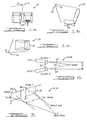
- FIGS. 1 a, 1 b and 1 crespectively illustrate front, side and top views of a three-dimensional (3-D) imaging system in a vehicle;
- FIG. 2illustrates an arrangement of cameras of a stereo vision system
- FIG. 4illustrates a 3-D imaging system using structured lighting
- FIG. 5illustrates an image of light stripes by a 3-D imaging system of FIG. 4 ;
- FIG. 6illustrates a triangulation of a point imaged by a 3-D imaging system using structured lighting
- FIG. 7illustrates a laser scanning system
- FIG. 8illustrates a coordinate system of the laser scanning system of FIG. 7 ;
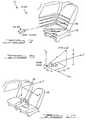
- FIGS. 9 a, 9 b, 9 c and 9 dillustrate viewing perspectives from the headliner, the driver side, the front, and the top respectively, of an occupant in the passenger side of a vehicle;
- FIG. 10illustrates a coordinate system in a vehicle
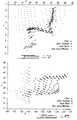
- FIG. 11illustrates an image of a passenger leaning forward, viewed from the headliner
- FIG. 12illustrates an image of a passenger leaning forward, viewed from the driver side using coordinate transformations
- FIG. 13illustrates an image of a passenger leaning forward, viewed from the front using coordinate transformations
- FIG. 14illustrates an image of a passenger leaning forward, viewed from the top using coordinate transformations
- FIG. 15illustrates an image of an empty seat, viewed from the headliner
- FIG. 16illustrates an image of an empty seat, viewed from the driver side using coordinate transformations
- FIG. 17illustrates an image of an empty seat, viewed from the front using coordinate transformations
- FIG. 18illustrates an image of an empty seat, viewed from the top using coordinate transformations
- FIG. 19is a flow chart of a process for sensing an occupant and for controlling a safety restraint system responsive thereto;
- FIG. 20is a flow chart of a segmentation process
- FIG. 21is a flow chart of a classification process
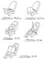
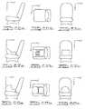
- FIGS. 22 a and 22 brespectively illustrate an uncovered, and a covered, rear facing infant seat located on a passenger seat of a vehicle;
- FIG. 23illustrates a front facing infant seat located on a passenger seat of a vehicle
- FIG. 24illustrates a belted occupant seated on a passenger seat of a vehicle
- FIG. 25illustrates an occupant reading a newspaper seated on a passenger seat of a vehicle
- FIGS. 26 a, 26 b and 26 cillustrate projections of an empty seat, on the YZ, XZ and XY planes respectively;
- FIGS. 27 a, 27 b and 27 cillustrate projections of a rear facing infant seat, on the YZ, XZ and XY planes respectively;
- FIGS. 28 a, 28 b and 28 cillustrate projections of an covered rear facing infant seat, on the YZ, XZ and XY planes respectively;
- FIGS. 29 a, 29 b and 29 cillustrate projections of a front facing infant, on the YZ, XZ and XY planes respectively;
- FIGS. 30 a, 30 b and 30 cillustrate projections of an occupant, on the YZ, XZ and XY planes respectively;
- FIGS. 31 a, 31 b and 31 cillustrate projections of an occupant, reading a newspaper, on the YZ, XZ and XY planes respectively;
- FIG. 32illustrates an at-risk zone within which an occupant would be out-of-position (OOP) and at risk of injury by the actuation of an associated air bag inflator module;
- OOPout-of-position
- FIG. 33illustrates a leg occupancy region in front of a seat cushion
- FIGS. 35 a and 35 billustrate a bounding rectangle for a RFIS and a normally seated occupant, respectively;
- FIGS. 36 a and 36 billustrate a best fit ellipse for a RFIS and a normally seated occupant, respectively.
- occupant sensor 10comprises at least one imaging device 12 in a three-dimensional (3-D) imaging system 14 that provides a 3-D image of a scene of a front passenger seat 16 of a vehicle.
- the 3-D imagecomprises a set of ‘voxels’, or three-dimensional pixels, each consisting of x, y an z coordinates with respect to a rectangular coordinate system.
- the 3-D imaging system 14can be located at a variety of locations in view of the seat 16 , for example, at the headliner above the rear view mirror and pointing towards the passenger seat 16 , so as to provide the maximum field of view with minimal obstruction. This location reduces the exposure of the 3-D imaging system 14 to direct sunlight and has minimal affect on the appearance of the vehicle interior.
- 3-D imaging techniquesare capable of providing range images, for example 1) stereo vision, 2) structured lighting and 3) scanning beam (e.g. scanning laser), any of which techniques could be embodied by the 3-D imaging system 14 .
- a first embodiment of a 3-D imaging system 14is illustrated by a stereo vision system 18 comprising a pair of substantially identical cameras 20 . 1 , 20 . 2 (e.g. CCD, CMOS or other technologies) with substantially identical optics 22 spaced apart by a small base distance d.
- the angle 24 between the respective optic axes 26 of the camerasis exaggerated in FIG. 2 .
- the stereo vision system 18can be made relatively small.
- LED 2can be adapted with a logarithmic response to provide a relatively high dynamic range, so as to prevent or limit saturation when targets are illuminated by sunlight hits the targets, while at the same time providing sufficient contrast under low ambient lighting conditions, for example at night time, perhaps with minimal supplemental infrared (IR) illumination provided by an infrared light emitting diodes (LED) or other illumination source.
- IRinfrared
- LEDlight emitting diodes
- low power LED'sare relatively inexpensive and safe, and provide illumination that is invisible to the human eye—thereby not a distraction—and can be automatically turned on to improve the overall contrast and average intensity of the images, for example if the overall contrast and average intensity are otherwise low.
- Each camera 20 . 1 , 20 . 2captures a respective image 28 . 1 , 28 . 2 of the same scene.
- similar objects in the two imagesare identified by registration thereof with one another, and the 2-D Cartesian coordinates (x 1 , y 1 ) and (x 2 , y 2 ) respectively corresponding to a common point of the object are determined from the pixel location with respect to the camera coordinate system (x, y). If the world coordinate system (X, Y, Z) coincides with that of camera 20 .
- This techniqueis dependent on the object being imaged having sufficient detail so as to enable the detection thereof from the correlation of the separate stereo images 28 . 1 , 28 . 2 .
- a pattern of infrared spotscan be projected on the scene (similar to the structured lighting approach described below), wherein these spots are used as the reference points that are matched by in the stereo analysis
- the signal to noise ratio of the imaged light pattern 38can be improved by strobing the light pattern 38 at half the frequency of the frame rate of the camera 36 so that alternate images have the light pattern 38 superimposed on the image of the target 32 , and the remaining images do not.
- Subtracting an image frame without a superimposed light pattern 38 from an adjacent image frame with the superimposed light patternprovides a resultant image—for a stationary background—of substantially only the light pattern 38 , as illustrated in FIG. 5 .
- the light pattern 38can be made brighter than sunlight, even with a relatively lower power density, because the light pattern 38 is strobed and the whole scene can be illuminated for a relatively brief time interval with relatively bright light from the light pattern generator 30 . Accordingly, the subtraction process for extracting the light pattern 38 can be done under arbitrary lighting conditions without compromising occupant safety.
- the spacing of the lines 40 of the light pattern 38 superimposed on the target 32depends on the distance of the target from the 3-D imaging system 14 , and the distortion thereof depends on the shape of the target 32 .
- the actual 3-D coordinatesare measured using triangulation of the light spots that constitute the light pattern 38 .
- the exemplary generated light pattern 38comprises a series of parallel lines 40 , for example, N parallel lines 40 , wherein each line 40 comprises a collection of light points, for example, M light points on each line 40 (as determined by the resolution of the camera 36 ).
- Each line 40results from the projection of an associated light plane on the target 32 .
- the 3-D imaging system 14provides a set of 3-D coordinates of the scene.
- the resulting 3-D datais used in an occupant sensing process that can be used for controlling the actuation of a safety restraint system.
- the location—i.e. the orientation and position—of the coordinate systems of the camera(s) and the world coordinate systemare fixed.
- the 3-D coordinates of a point on a target 32can be expressed with respect to any world coordinate system at any position and orientation using coordinate transformations.
- the 3-D image taken from the fixed location at the headlinercan be effectively viewed from any other location of choice (for example, from the headliner, either of the A-pillars, the dashboard, the driver side or other locations) by using one or more coordinate transformations.
- FIGS. 9 a-dillustrate a laboratory setup of a vehicle interior buck viewed from four different perspectives as follows: from headliner ( FIG. 9 a ), from the driver side ( FIG. 9 b ), from the front ( FIG. 9 c ) and from the top ( FIG. 9 d ).
- FIG. 10for the coordinate system origin at the headliner above the rear view mirror as illustrated in FIG. 9 a, the positive x axis is horizontal and towards the driver side, the positive y axis is vertical and towards the floor and the positive z axis is horizontal and towards the back of the vehicle.
- 3-D image datawas collected from this location using an infrared scanning laser range finder 42 .
- the respective images from the headliner locationare shown in FIGS. 11 and 15 respectively.
- These same imagesare respectively transformed to the viewing perspectives of the driver side, the front and the top by transformation of coordinate systems, as shown in FIGS. 12 through 14 respectively for the occupant seated leaning slightly forward, and in FIGS. 16 through 18 respectively for the empty seat.
- segmentationmeans the extraction from the image of a region of interest (ROI) that contains useful information.
- ROIregion of interest
- FIGS. 19 and 20the side door, A-pillar, dashboard, floor and objects outside the window are all examples of background clutter that can be and preferably are eliminated from the image by segmentation, leaving as a remainder the ROI. This reduces the number of data points that need to be processed by a recognition algorithm.
- the dashboard, side door and the floorcan be characterized as fixed planes.
- this planeis fixed and g, h, i and n are fixed parameters of the vehicle.
- the points on the doorare eliminated by comparing a linear combination of the data points (X, Y, Z) with a threshold, as follows: g ⁇ X+h ⁇ Y+i ⁇ Z ⁇ n ⁇ T 0 (threshold) (11) wherein those points satisfying equation (11) are sufficiently close to the fixed plane to be assumed to be associated with the door.
- the function ⁇ (x, y, z)cannot be expressed in a standard form, then the function can, for example, be characterized by a least squares fit of a functional form, using the actual 3-D coordinates of the A-pillar. The same process can be used in modeling a dashboard of a nonstandard shape.
- the portion of the empty seat that is visibleis also be segmented out.
- the imageis analyzed to determine whether or not the seat is empty.
- the imagecomprises a seat cushion (bottom) and a seat back, which can be respectively characterized by two respective planes—a first plane characterizing the seat cushion and a second plane, at an angle relative to the first, characterizing the seat back.
- T[ 1 0 0 0 0 1 0 0 0 0 1 z 0 0 0 1 ] ( 16 )
- R ⁇[ 1 0 0 0 0 0 cos ⁇ ⁇ ⁇ sin ⁇ ⁇ ⁇ 0 0 - sin ⁇ ⁇ ⁇ cos ⁇ ⁇ ⁇ 0 0 0 0 1 ] ( 17 )
- Clusters of points lying on the seat cushion plane of equation (24) and seat back plane of equation (19)are checked to see if they form the rough shape of the seat cushion and back respectively, by checking test points (X, Y, Z) to see if the following equations are satisfied: a ⁇ X+b ⁇ Y+c ⁇ Z ⁇ k ⁇ T 3 (threshold) (25) d ⁇ ,z ⁇ X+e ⁇ ,z ⁇ Y+f ⁇ ,z ⁇ Z ⁇ m ⁇ ,z ⁇ T 4 (threshold) (26) for all possible combinations of seat cushion position and seat cushion slope and seat back angle.
- FFISforward facing infant or child seat
- RFISradio frequency
- the imageis then searched to find a somewhat spherical shape representing a head.
- the image of the targethas a dominant spherical region.
- the searchbegins with a reasonable guess as to where the head is likely to be in 3-D space for the particular vehicle, after which the position of the center of the sphere, and the radius of the sphere, are respectively iterated by the search.
- the imageis then searched to find cylindrical surfaces representing the arms and legs.
- the torsois characterized by a relatively flat surface. Semantics are used—a spherical surface (head) with two cylindrical surfaces (arms) on both sides, a relatively less curved surface (torso) below the spherical surface (head) and in between the two cylindrical surfaces (arms), the cylindrical surfaces (arms) originating from the top of the less curved surface (torso), two more cylindrical surfaces (legs) originating from the bottom of the less curved surface (torso)—all indicate an occupant.
- the size of these featurescan be roughly determined to distinguish the size of the occupant, e.g. large, medium or small.
- a RFISmay be uncovered or covered. A substantial portion of the seat back is visible for either of these cases, but more so with the uncovered RFIS.
- a ‘kidney bean’ shapeis indicative of the uncovered RFIS, in which case two small cylindrical surfaces maybe visible on the right representing the legs of the infant.
- a somewhat smooth surfaceis indicative of a covered RFIS.
- an occupant in a FFIS or booster seatis indicated if all of the above limbs are visible and they are relatively small, and if the occupant is not seated directly on the seat, but is somewhat raised thereabove, as indicated by an outer boundary of the occupant zone that is not completely planar.
- a child in a booster seatis indicated if the seatback is visible but the occupant is seated on a raised surface, as determined by looking at the buttocks region to see how far it is from the seat cushion plane.
- seatbelt usagemay also be determined from surface characteristic, for example, the presence of a somewhat elongated and arched surface.
- an occupant reading a newspaperis identified by looking for a large planar surface on the left of the scene and likely a spherical surface because the head may be seen from over the newspaper.
- Equation (27)provides for spatial invariance so that the moment values will be the same for similar ROI's regardless of their corresponding location in the vehicle. For example, the central moments of a RFIS would be the same for any position of the vehicle seat.
- Centroidsprovide a position in 3-D space that can be a useful indicator of the seat occupancy scenario. For example, referring to FIG. 10 , a RFIS would be closer to the instrument panel, thus having a lower ⁇ overscore (z) ⁇ value, than would a normally seated occupant having a higher ⁇ overscore (z) ⁇ value.
- the ⁇ overscore (x) ⁇ valueprovides the lateral position of the target, thus providing an indication if an occupant is seated in the middle of a bench seat.
- the ⁇ overscore (y) ⁇ centroidenables tall objects to be distinguished from short objects—a RFIS tends to be lower thus having a lower ⁇ overscore (y) ⁇ value as compared to that of a normally seated occupant.
- Occupantschild seats and empty seats typically have different volumes. This feature is especially useful in determining the size of the occupant, once the image has been classified.
- Ratio of RadiiA radius is a line segment joining the centroid to any point on the outer boundary of the ROI.
- Targets with large portions sticking out from the main bodywill have a large V B compared to its volume V since a large portion of the bounding rectangles typically contain more than the projections of the ROI.
- the 2-D features calculated on the three projections of the ROIprovide substantial shape information. These 2-D features are illustrated hereinbelow for the projection on the XY plane. The corresponding features for the projections on the YZ and ZX planes are determined by replacing (x, y) by (y, z) and (z, x) respectively:
- the perimeter of the projection of an empty seatis likely to be less than that of an occupied seat.
- k ⁇ ( t )( d 2 ⁇ x d t 2 ) 2 + ( d 2 ⁇ y d t 2 ) 2 ( 54 ) and t is the distance along the perimeter from any arbitrary starting point on the perimeter.
- the bending energyis high for shapes with many sharp bends as would result for occupants. Child seats would tend to have a lower value of bending energy.
- Occupantsare more ‘elongated’ than child seats especially when viewed from the driver side. Accordingly, the ellipse bounding them would typically be substantially different from an ellipse bounding a child seat. Stated another way, the features describing the ellipse for an occupant are typically different from those for child seats and empty seats.
- the central axis lines for a RFIS and a normally seated occupanttypically have different curvatures. Accordingly, the coefficients a 1 and a 2 are features that indicate the curvature of the central axis line.
- the classificationis done, for example, using a minimum distance classifier, whereby the detected scene is the one for which the corresponding golden feature vector is nearest (d s is minimum) to the test feature vector.
- the distance of the identified scene or portions of the scene from the instrument panelis then identified by looking at the coordinates from a perspective perpendicular to the length of the vehicle. Therefore, it can be determined whether the identified target is within an “at-risk” zone, regardless of shape or size.
- the lateral position of the occupant/objectcan also be determined using the 3-D coordinates.
- the position of the identified parts of the occupantis found in 3-D space, which aids in identifying an out of position (OOP) occupant, regardless of the size and shape of the “at-risk” zone and regardless of the definition of an OOP occupant (e.g. whether or not hands inside the “at-risk” zone constitutes an OOP occupant), which is useful for situations with dynamic “at-risk” zones.
- OOPout of position
- the 3-D dataalso provides a rough estimate of the volume, and accordingly the size of the occupant—if present,—which information can be used to control the deployment of the airbag.
- the decision for the deployment of the airbag or the type of deploymentcan be determined, for example, as follows: the air bag would be turned off for RFIS or occupants at certain postures deemed at risk from the airbag (out of position (OOP) occupant), the deployment may be softer for a smaller occupant closer to the dashboard.
- the occupant sensor 10can be used on the driver side by imaging the driver, for example from the same headliner location as used to image the passenger, in order to determine the size of the driver, and the position of the torso, head and arms, any of which can be used to track the driver's movement over time, in order to tailor the deployment of the airbag.
- the 3-D imaging system 14acquires range images, which differ from 2-D images in that the pixel values represent distances from the imaging system, as opposed to intensity.
- range imageswhich differ from 2-D images in that the pixel values represent distances from the imaging system, as opposed to intensity.
- the scenecan be viewed from any perspective by translating and/or rotating the coordinate axes.
- the segmentation processbecomes easier and more robust as the background clutter outside the window can be eliminated since their position in 3-D space is known.
- the fixed objects (dashboard, door etc) in viewcan be eliminated since they have fixed coordinates.
- the shape descriptorscontain more separable information to enhance the classification of the scene—these give an idea of the 3-D volume versus the 2-D shape.
- each data pointcan be clearly determined with respect to any part of the vehicle thus enabling the detection of an out of position (OOP) occupant, which is defined as some part of the occupant within some predefined “at-risk” zone.
- OOPout of position
- an OOP occupantcan be determined for an “at-risk” zone of arbitrary shape or size.
- arbitrary pointscan be tracked over time thus enabling the tracking of the occupant during pre-crash or even crash periods.
- the approximate volume and hence the size of the targetcan be determined.
- the above-described 3-D imaging system 14incorporates an image processor and associated electronics for acquiring and processing the associated imaging data.
- the safety restraint systemis controlled responsive to the above-described processing of the imaging data, either by the image processor, or by a separate control processor.
- the safety restraint systemis actuated responsive to a crash as detected by a crash sensor, provided that the actuation thereof is enabled responsive to the above-described image processing by the image processor.
Landscapes
- Engineering & Computer Science (AREA)
- Physics & Mathematics (AREA)
- General Physics & Mathematics (AREA)
- Theoretical Computer Science (AREA)
- Computer Networks & Wireless Communication (AREA)
- Radar, Positioning & Navigation (AREA)
- Remote Sensing (AREA)
- Computer Vision & Pattern Recognition (AREA)
- Electromagnetism (AREA)
- Mechanical Engineering (AREA)
- Human Computer Interaction (AREA)
- Multimedia (AREA)
- Air Bags (AREA)
- Image Processing (AREA)
- Image Analysis (AREA)
- Geophysics And Detection Of Objects (AREA)
Abstract
Description
where, λ is the focal length of the lenses of the cameras
The coordinates are independent of γk, the angle made by the kthlight plane with the ZX plane.
(3) Scanning Laser
X0=R·cos θ·sin α (7)
Y0=R·sin θ (8)
Z0=R·cos θ·cos α (9)
Data Analysis
g·x+h·y+i·z=n (10)
g·X+h·Y+i·Z−n<T0(threshold) (11)
wherein those points satisfying equation (11) are sufficiently close to the fixed plane to be assumed to be associated with the door.
f(x, y, z)=s (12)
f(X, Y, Z)−s<T1(threshold) (13)
Points outside the side window—for example, having large negative x coordinates—are discarded by comparing with a threshold T2corresponding to the distance from the origin of the coordinate system to the side door plane that is roughly parallel to the YZ plane. Therefore, the point (X Y, Z) is outside if:
X<−T2 (14)
d·x+e·y+f·z=m (15)
wherein the parameters d, e, f and m are fixed for a particular vehicle. The angle of the seatback and the position and recline of the seat cushion are all variable, so the equation of the seat back plane is a function of these three factors. Referring to
dα,z·x+eα,z·y+f60 ,z·z=mα,z (19)
where,
dα,z=d (20)
eα,z=e·cos α−f·sin α (21)
fα,z=e·sin α+f·cos α+f (22)
mα,z=m (23)
a·x+b·y+c·z=k (24)
wherein the parameters a, b, c and k are fixed for a particular vehicle. The equation of the plane for any other tilt of the seat cushion is found by applying the above described rotational transformation about the X axis.
a·X+b·Y+c·Z−k<T3(threshold) (25)
dα,z·X+eα,z·Y+fα,z·Z−mα,z<T4(threshold) (26)
for all possible combinations of seat cushion position and seat cushion slope and seat back angle.
where ({overscore (x)}, {overscore (y)}, {overscore (z)}) is the centroid of the ROI from equations (29-31). The moment of order p, q, r is defined by:
V=m000 (32)
Rv=6·π2·V/pv3 (33)
where, V is the volume and pvis the average of the perimeters of the projections of the ROI on the XY, YZ and ZX planes. Child seats tend to be more ‘spherical’ than people. Moreover, the empty seat has a different roundness.
rR=Rmax/Rmin (34)
This measure is roughly analogous to aspect ratio—‘thinner’ objects, for example occupants and empty seats, typically have a higher value than ‘compact’ objects, for example child seats.
- (6) Volume of the Bounding Cube: The geometric mean of the areas of the bounding rectangles for the three projections of equation (56) is the volume of the bounding cube, as given by:
VB=√{square root over (ABxyAByzABzx)} (35)
where, - ABxy=Area of the rectangle bounding the XY projection of the 3-D ROI;
- AByx=Area of the rectangle bounding the YZ projection of the 3-D ROI; and
- ABzx=Area of the rectangle bounding the ZX projection of the 3-D ROI.
This is another way of analyzing the volume of the target.
- (6) Volume of the Bounding Cube: The geometric mean of the areas of the bounding rectangles for the three projections of equation (56) is the volume of the bounding cube, as given by:
Rv=V/VB (36)
RVp=Vo/Vp (37)
wherein the centroids are given by:
φ1=η20+η02 (43)
φ2=(η20−η02)2+4η112 (44)
φ3=(η30−3η12)2+(3η21−η03)2 (45)
φ4=(η30+η12)2+(η21+η03)2 (46)
The perimeter of the projection of an empty seat is likely to be less than that of an occupied seat.
A=m00 (51)
The area of the projection of an empty seat is likely to be less than that of a RFIS, FFIS or occupant.
R=4πA/p2 (52)
A RFIS would have a different measure of roundness than an occupant or an empty seat.
and t is the distance along the perimeter from any arbitrary starting point on the perimeter. The bending energy is high for shapes with many sharp bends as would result for occupants. Child seats would tend to have a lower value of bending energy.
This feature is relatively strong for the projection on the YZ plane since the RFIS would be tilted leftwards, as illustrated in
Ab=Lb·Wb (56)
where, first the projection is rotated by θ (the orientation):
α=x·cos θ+y·sin θ (57)
β=−x·sin θ+y·cos θ (58)
and then the length (Lb) and width (Wb) of the rectangle are determined from:
Lb=(αmax−αmin (59)
Wb=βmax−βmin (60)
This measure is typically different for different images.
where,
R is the region consisting of the projection.
Area of the ellipse=Aellipse=π·a·b (65)
Eccentric normal=Nellipse=2b2/a (69)
Occupants typically have a larger eccentricity than those of child seats and empty seats because occupants are typically more elongated.
Ra=A/Ab (71)
This measure is relatively small for regions with large protruding parts. e.g., occupants with arms extended.
f(x)=a0+a1·x+a2·x2 (72)
f=[f1f2f3. . . fn]T (73)
the test feature vector is compared with reference (or “golden”) feature vectors for the various scenarios fs, where s is the scenario, for example s⊂{RFIS, FFIS, Occupant, Empty Seat}
fs=[fs1fs2fs3. . . fsn]T (74)
by comparing the vector distance ds
Claims (15)
Priority Applications (1)
| Application Number | Priority Date | Filing Date | Title |
|---|---|---|---|
| US09/882,959US6961443B2 (en) | 2000-06-15 | 2001-06-15 | Occupant sensor |
Applications Claiming Priority (2)
| Application Number | Priority Date | Filing Date | Title |
|---|---|---|---|
| US21184600P | 2000-06-15 | 2000-06-15 | |
| US09/882,959US6961443B2 (en) | 2000-06-15 | 2001-06-15 | Occupant sensor |
Publications (2)
| Publication Number | Publication Date |
|---|---|
| US20020050924A1 US20020050924A1 (en) | 2002-05-02 |
| US6961443B2true US6961443B2 (en) | 2005-11-01 |
Family
ID=22788557
Family Applications (1)
| Application Number | Title | Priority Date | Filing Date |
|---|---|---|---|
| US09/882,959Expired - LifetimeUS6961443B2 (en) | 2000-06-15 | 2001-06-15 | Occupant sensor |
Country Status (4)
| Country | Link |
|---|---|
| US (1) | US6961443B2 (en) |
| EP (1) | EP1297486A4 (en) |
| JP (1) | JP4810052B2 (en) |
| WO (1) | WO2001096147A2 (en) |
Cited By (57)
| Publication number | Priority date | Publication date | Assignee | Title |
|---|---|---|---|---|
| US20020044682A1 (en)* | 2000-09-08 | 2002-04-18 | Weil Josef Oster | Method and apparatus for subject physical position and security determination |
| US20030156756A1 (en)* | 2002-02-15 | 2003-08-21 | Gokturk Salih Burak | Gesture recognition system using depth perceptive sensors |
| US20030165048A1 (en)* | 2001-12-07 | 2003-09-04 | Cyrus Bamji | Enhanced light-generated interface for use with electronic devices |
| US20030169906A1 (en)* | 2002-02-26 | 2003-09-11 | Gokturk Salih Burak | Method and apparatus for recognizing objects |
| US20030204384A1 (en)* | 2002-04-24 | 2003-10-30 | Yuri Owechko | High-performance sensor fusion architecture |
| US20040040772A1 (en)* | 2000-12-20 | 2004-03-04 | Ludwig Ertl | Method and device for detecting an object in a vehicle in particular for occupant protection systems |
| US20040066500A1 (en)* | 2002-10-02 | 2004-04-08 | Gokturk Salih Burak | Occupancy detection and measurement system and method |
| US20040153229A1 (en)* | 2002-09-11 | 2004-08-05 | Gokturk Salih Burak | System and method for providing intelligent airbag deployment |
| US20040256541A1 (en)* | 2001-01-19 | 2004-12-23 | Honeywell International Inc. | Method and apparatus for detecting objects using structured light patterns |
| US20050070024A1 (en)* | 2003-09-30 | 2005-03-31 | Nguyen Hoa Duc | Method of analysis of alcohol by mass spectrometry |
| US20050088643A1 (en)* | 2003-09-15 | 2005-04-28 | Anderson Noel W. | Method and system for identifying an edge of a crop |
| US20050111700A1 (en)* | 2003-10-03 | 2005-05-26 | O'boyle Michael E. | Occupant detection system |
| US20050196035A1 (en)* | 2004-03-03 | 2005-09-08 | Trw Automotive U.S. Llc | Method and apparatus for producing classifier training images |
| US20050238206A1 (en)* | 2002-06-18 | 2005-10-27 | Siemens Aktiengesellschaft | Method and device for identifying individuals |
| US20060132635A1 (en)* | 2004-12-20 | 2006-06-22 | Land Jay E | Single axis CCD time gated ladar sensor |
| US20060138759A1 (en)* | 2004-12-24 | 2006-06-29 | Takata Corporation | Detection system, occupant protection device, vehicle, and detection method |
| US20060145824A1 (en)* | 2003-05-08 | 2006-07-06 | Henryk Frenzel | Method and device for detecting an object or a person |
| US20060180764A1 (en)* | 2005-01-28 | 2006-08-17 | Matsuda Micronics Corporation | Passenger detection apparatus |
| US20060280336A1 (en)* | 2005-06-08 | 2006-12-14 | Lee Seok J | System and method for discriminating passenger attitude in vehicle using stereo image junction |
| US7151530B2 (en) | 2002-08-20 | 2006-12-19 | Canesta, Inc. | System and method for determining an input selected by a user through a virtual interface |
| US20060291697A1 (en)* | 2005-06-21 | 2006-12-28 | Trw Automotive U.S. Llc | Method and apparatus for detecting the presence of an occupant within a vehicle |
| US20070085669A1 (en)* | 2003-07-15 | 2007-04-19 | Guido Becker | Seat-belt warning device |
| US20070124045A1 (en)* | 2005-11-29 | 2007-05-31 | Ayoub Ramy P | System and method for controlling the processing of content based on zones in vehicles |
| US20070124044A1 (en)* | 2005-11-29 | 2007-05-31 | Ayoub Ramy P | System and method for controlling the processing of content based on vehicle conditions |
| US20070124046A1 (en)* | 2005-11-29 | 2007-05-31 | Ayoub Ramy P | System and method for providing content to vehicles in exchange for vehicle information |
| US20070124043A1 (en)* | 2005-11-29 | 2007-05-31 | Ayoub Ramy P | System and method for modifying the processing of content in vehicles based on vehicle conditions |
| US20070120697A1 (en)* | 2005-11-29 | 2007-05-31 | Ayoub Ramy P | Method and device for determining a location and orientation of a device in a vehicle |
| US7245741B1 (en)* | 2000-11-14 | 2007-07-17 | Siemens Aktiengesellschaft | Method and device for determining whether the interior of a vehicle is occupied |
| US20070229662A1 (en)* | 2006-04-04 | 2007-10-04 | Takata Corporation | Object detecting system and method |
| US20070229661A1 (en)* | 2006-04-04 | 2007-10-04 | Takata Corporation | Object detecting system and method |
| US20080255731A1 (en)* | 2007-04-12 | 2008-10-16 | Takata Corporation | Occupant detection apparatus |
| US20080252725A1 (en)* | 2005-09-26 | 2008-10-16 | Koninklijke Philips Electronics, N.V. | Method and Device for Tracking a Movement of an Object or of a Person |
| US20080317355A1 (en)* | 2007-06-21 | 2008-12-25 | Trw Automotive U.S. Llc | Method and apparatus for determining characteristics of an object from a contour image |
| US20090010495A1 (en)* | 2004-07-26 | 2009-01-08 | Automotive Systems Laboratory, Inc. | Vulnerable Road User Protection System |
| US7561732B1 (en)* | 2005-02-04 | 2009-07-14 | Hrl Laboratories, Llc | Method and apparatus for three-dimensional shape estimation using constrained disparity propagation |
| US20100060736A1 (en)* | 2007-03-07 | 2010-03-11 | Bin Shi | Vehicle Interior Classification System And Method |
| US20100067738A1 (en)* | 2008-09-16 | 2010-03-18 | Robert Bosch Gmbh | Image analysis using a pre-calibrated pattern of radiation |
| US20100087982A1 (en)* | 2008-10-08 | 2010-04-08 | Allen Brian T | Methods For Testing An Image Based Occupant Classification System |
| US20100086178A1 (en)* | 2008-10-08 | 2010-04-08 | Allen Brian T | Illumination Source For An Image Based Occupant Classification System And Vehicle Using Same |
| US20100087990A1 (en)* | 2008-10-08 | 2010-04-08 | Allen Brian T | Image Based Occupant Classification Systems For Determining Occupant Classification And Seat Belt Status And Vehicles Having Same |
| US20100182425A1 (en)* | 2009-01-21 | 2010-07-22 | Mazda Motor Corporation | Vehicle interior state recognition device |
| US20110080490A1 (en)* | 2009-10-07 | 2011-04-07 | Gesturetek, Inc. | Proximity object tracker |
| US20110286676A1 (en)* | 2010-05-20 | 2011-11-24 | Edge3 Technologies Llc | Systems and related methods for three dimensional gesture recognition in vehicles |
| US8768007B2 (en) | 2012-03-26 | 2014-07-01 | Tk Holdings Inc. | Method of filtering an image |
| US8824733B2 (en) | 2012-03-26 | 2014-09-02 | Tk Holdings Inc. | Range-cued object segmentation system and method |
| US8831287B2 (en)* | 2011-06-09 | 2014-09-09 | Utah State University | Systems and methods for sensing occupancy |
| TWI502979B (en)* | 2012-02-13 | 2015-10-01 | Altek Corp | Image motion estimation method |
| US9165368B2 (en) | 2005-02-08 | 2015-10-20 | Microsoft Technology Licensing, Llc | Method and system to segment depth images and to detect shapes in three-dimensionally acquired data |
| TWI511547B (en)* | 2012-04-10 | 2015-12-01 | Acer Inc | Method for assisting in video compression using rotation operation and image capturing device thereof |
| US9349058B2 (en) | 2012-10-31 | 2016-05-24 | Tk Holdings, Inc. | Vehicular path sensing system and method |
| US9446730B1 (en)* | 2015-11-08 | 2016-09-20 | Thunder Power Hong Kong Ltd. | Automatic passenger airbag switch |
| TWI573434B (en)* | 2008-07-24 | 2017-03-01 | 皇家飛利浦電子股份有限公司 | Versatile 3-d picture format |
| TWI581612B (en)* | 2011-11-07 | 2017-05-01 | 英孚布瑞智有限私人貿易公司 | Method of exporting motion information |
| US10083361B2 (en) | 2013-03-15 | 2018-09-25 | Joyson Safety Systems Acquisition Llc | Path sensing using structured lighting |
| US10242255B2 (en) | 2002-02-15 | 2019-03-26 | Microsoft Technology Licensing, Llc | Gesture recognition system using depth perceptive sensors |
| US20210052176A1 (en)* | 2018-02-22 | 2021-02-25 | Vayyar Imaging Ltd. | Radar-based classification of vehicle occupants |
| US11210539B2 (en) | 2019-04-04 | 2021-12-28 | Joyson Safety Systems Acquisition Llc | Detection and monitoring of active optical retroreflectors |
Families Citing this family (54)
| Publication number | Priority date | Publication date | Assignee | Title |
|---|---|---|---|---|
| US6772057B2 (en) | 1995-06-07 | 2004-08-03 | Automotive Technologies International, Inc. | Vehicular monitoring systems using image processing |
| US6856873B2 (en) | 1995-06-07 | 2005-02-15 | Automotive Technologies International, Inc. | Vehicular monitoring systems using image processing |
| JP4006577B2 (en)* | 2002-03-13 | 2007-11-14 | オムロン株式会社 | Monitoring device |
| US7088113B2 (en)* | 2002-07-08 | 2006-08-08 | Intelligent Mechatronic Systems Inc. | Integrated occupant sensory system |
| ITTO20030197A1 (en) | 2003-03-14 | 2004-09-15 | Fiat Ricerche | ELECTRO-OPTICAL DEVICE ACTIVE FOR THE DETECTION OF |
| JP3843971B2 (en)* | 2003-07-29 | 2006-11-08 | 日産自動車株式会社 | Occupant detection device |
| DE10337852A1 (en)* | 2003-08-18 | 2005-03-17 | Robert Bosch Gmbh | vehicle system |
| US7831087B2 (en)* | 2003-10-31 | 2010-11-09 | Hewlett-Packard Development Company, L.P. | Method for visual-based recognition of an object |
| US20050175243A1 (en)* | 2004-02-05 | 2005-08-11 | Trw Automotive U.S. Llc | Method and apparatus for classifying image data using classifier grid models |
| US20050175235A1 (en)* | 2004-02-05 | 2005-08-11 | Trw Automotive U.S. Llc | Method and apparatus for selectively extracting training data for a pattern recognition classifier using grid generation |
| US7471832B2 (en)* | 2004-02-24 | 2008-12-30 | Trw Automotive U.S. Llc | Method and apparatus for arbitrating outputs from multiple pattern recognition classifiers |
| US8280482B2 (en)* | 2004-04-19 | 2012-10-02 | New York University | Method and apparatus for evaluating regional changes in three-dimensional tomographic images |
| US7561731B2 (en)* | 2004-12-27 | 2009-07-14 | Trw Automotive U.S. Llc | Method and apparatus for enhancing the dynamic range of a stereo vision system |
| US7283901B2 (en)* | 2005-01-13 | 2007-10-16 | Trw Automotive U.S. Llc | Controller system for a vehicle occupant protection device |
| JP4623501B2 (en)* | 2005-02-18 | 2011-02-02 | タカタ株式会社 | Detection system, notification device, drive device, vehicle |
| US7646916B2 (en)* | 2005-04-15 | 2010-01-12 | Mississippi State University | Linear analyst |
| US20070143065A1 (en)* | 2005-12-05 | 2007-06-21 | Griffin Dennis P | Scanned laser-line sensing apparatus for a vehicle occupant |
| JP2007218626A (en) | 2006-02-14 | 2007-08-30 | Takata Corp | Object detecting system, operation device control system, vehicle |
| JP2007216722A (en) | 2006-02-14 | 2007-08-30 | Takata Corp | Object detection system, actuator control system, vehicle |
| JP2008002838A (en)* | 2006-06-20 | 2008-01-10 | Takata Corp | Vehicle occupant detection system, actuator control system, vehicle |
| JP2008001136A (en)* | 2006-06-20 | 2008-01-10 | Takata Corp | Vehicle occupant seat detection system, operating device control system, and vehicle |
| US20080075327A1 (en)* | 2006-09-21 | 2008-03-27 | Honeywell International Inc. | Method and system for object characterization based on image volumetric determination |
| AU2007351713B2 (en)* | 2007-04-20 | 2011-11-17 | Softkinetic Software | Volume recognition method and system |
| US20100014711A1 (en)* | 2008-07-16 | 2010-01-21 | Volkswagen Group Of America, Inc. | Method for controlling an illumination in a vehicle interior in dependence on a head pose detected with a 3D sensor |
| JP2010195139A (en)* | 2009-02-24 | 2010-09-09 | Takata Corp | Occupant restraint control device and occupant restraint control method |
| US8553989B1 (en)* | 2010-04-27 | 2013-10-08 | Hrl Laboratories, Llc | Three-dimensional (3D) object recognition system using region of interest geometric features |
| JP2012000165A (en)* | 2010-06-14 | 2012-01-05 | Sega Corp | Video game apparatus |
| JP5401440B2 (en)* | 2010-12-14 | 2014-01-29 | 本田技研工業株式会社 | Crew head detection device |
| JP5396377B2 (en)* | 2010-12-15 | 2014-01-22 | 本田技研工業株式会社 | Vacant seat determination device and vacant seat determination method |
| JP5453229B2 (en)* | 2010-12-15 | 2014-03-26 | 本田技研工業株式会社 | Occupant discrimination device and occupant discrimination method |
| JP5453230B2 (en)* | 2010-12-15 | 2014-03-26 | 本田技研工業株式会社 | Occupant detection device |
| US10307104B2 (en) | 2011-07-05 | 2019-06-04 | Saudi Arabian Oil Company | Chair pad system and associated, computer medium and computer-implemented methods for monitoring and improving health and productivity of employees |
| US9844344B2 (en) | 2011-07-05 | 2017-12-19 | Saudi Arabian Oil Company | Systems and method to monitor health of employee when positioned in association with a workstation |
| US10108783B2 (en) | 2011-07-05 | 2018-10-23 | Saudi Arabian Oil Company | Systems, computer medium and computer-implemented methods for monitoring health of employees using mobile devices |
| US9962083B2 (en) | 2011-07-05 | 2018-05-08 | Saudi Arabian Oil Company | Systems, computer medium and computer-implemented methods for monitoring and improving biomechanical health of employees |
| JP2014525086A (en) | 2011-07-05 | 2014-09-25 | サウジ アラビアン オイル カンパニー | Floor mat system and associated computer media for monitoring and improving employee health and productivity, and computer-implemented methods |
| US9492120B2 (en) | 2011-07-05 | 2016-11-15 | Saudi Arabian Oil Company | Workstation for monitoring and improving health and productivity of employees |
| US9526455B2 (en)* | 2011-07-05 | 2016-12-27 | Saudi Arabian Oil Company | Systems, computer medium and computer-implemented methods for monitoring and improving health and productivity of employees |
| US9710788B2 (en) | 2011-07-05 | 2017-07-18 | Saudi Arabian Oil Company | Computer mouse system and associated, computer medium and computer-implemented methods for monitoring and improving health and productivity of employees |
| DE102012208644B4 (en)* | 2011-11-23 | 2014-02-27 | Johnson Controls Gmbh | Device and method for adjusting a seating position |
| US9165190B2 (en) | 2012-09-12 | 2015-10-20 | Avigilon Fortress Corporation | 3D human pose and shape modeling |
| US9747680B2 (en) | 2013-11-27 | 2017-08-29 | Industrial Technology Research Institute | Inspection apparatus, method, and computer program product for machine vision inspection |
| US9722472B2 (en) | 2013-12-11 | 2017-08-01 | Saudi Arabian Oil Company | Systems, computer medium and computer-implemented methods for harvesting human energy in the workplace |
| US10642955B2 (en) | 2015-12-04 | 2020-05-05 | Saudi Arabian Oil Company | Devices, methods, and computer medium to provide real time 3D visualization bio-feedback |
| US10475351B2 (en) | 2015-12-04 | 2019-11-12 | Saudi Arabian Oil Company | Systems, computer medium and methods for management training systems |
| US9889311B2 (en) | 2015-12-04 | 2018-02-13 | Saudi Arabian Oil Company | Systems, protective casings for smartphones, and associated methods to enhance use of an automated external defibrillator (AED) device |
| US10628770B2 (en) | 2015-12-14 | 2020-04-21 | Saudi Arabian Oil Company | Systems and methods for acquiring and employing resiliency data for leadership development |
| US20170220870A1 (en)* | 2016-01-28 | 2017-08-03 | Pointgrab Ltd. | Method and system for analyzing occupancy in a space |
| JP6798299B2 (en) | 2016-12-16 | 2020-12-09 | アイシン精機株式会社 | Crew detector |
| DE102017204681A1 (en) | 2017-03-21 | 2018-09-27 | Robert Bosch Gmbh | Device for triggering an external protection function |
| US10824132B2 (en) | 2017-12-07 | 2020-11-03 | Saudi Arabian Oil Company | Intelligent personal protective equipment |
| WO2020105751A1 (en)* | 2018-11-21 | 2020-05-28 | 엘지전자 주식회사 | Method for monitoring occupant and device therefor |
| US12067744B2 (en)* | 2022-02-18 | 2024-08-20 | Dell Products, L.P. | Systems and methods for context-based detection of postures of a user of an IHS (information handling system) |
| WO2024141985A1 (en)* | 2022-12-30 | 2024-07-04 | Gentex Corporation | 3d skeleton detection for in-cabin automotive application |
Citations (23)
| Publication number | Priority date | Publication date | Assignee | Title |
|---|---|---|---|---|
| US4625329A (en) | 1984-01-20 | 1986-11-25 | Nippondenso Co., Ltd. | Position analyzer for vehicle drivers |
| US4933541A (en) | 1989-06-29 | 1990-06-12 | Canadian Patents And Development Ltd. - Societe Canadienne Des Brevets Et D'exploitation Limitee | Method and apparatus for active vision image enhancement with wavelength matching |
| US4954962A (en) | 1988-09-06 | 1990-09-04 | Transitions Research Corporation | Visual navigation and obstacle avoidance structured light system |
| US5016173A (en) | 1989-04-13 | 1991-05-14 | Vanguard Imaging Ltd. | Apparatus and method for monitoring visually accessible surfaces of the body |
| US5040116A (en) | 1988-09-06 | 1991-08-13 | Transitions Research Corporation | Visual navigation and obstacle avoidance structured light system |
| US5381236A (en) | 1991-02-12 | 1995-01-10 | Oxford Sensor Technology Limited | Optical sensor for imaging an object |
| US5398185A (en) | 1990-04-18 | 1995-03-14 | Nissan Motor Co., Ltd. | Shock absorbing interior system for vehicle passengers |
| US5528698A (en) | 1995-03-27 | 1996-06-18 | Rockwell International Corporation | Automotive occupant sensing device |
| US5531472A (en) | 1995-05-01 | 1996-07-02 | Trw Vehicle Safety Systems, Inc. | Apparatus and method for controlling an occupant restraint system |
| US5684898A (en) | 1993-12-08 | 1997-11-04 | Minnesota Mining And Manufacturing Company | Method and apparatus for background determination and subtraction for a monocular vision system |
| US5785347A (en) | 1996-10-21 | 1998-07-28 | Siemens Automotive Corporation | Occupant sensing and crash behavior system |
| US5835613A (en)* | 1992-05-05 | 1998-11-10 | Automotive Technologies International, Inc. | Optical identification and monitoring system using pattern recognition for use with vehicles |
| US5852672A (en) | 1995-07-10 | 1998-12-22 | The Regents Of The University Of California | Image system for three dimensional, 360 DEGREE, time sequence surface mapping of moving objects |
| US5871232A (en) | 1997-01-17 | 1999-02-16 | Automotive Systems, Laboratory, Inc. | Occupant position sensing system |
| US5877801A (en)* | 1991-05-13 | 1999-03-02 | Interactive Pictures Corporation | System for omnidirectional image viewing at a remote location without the transmission of control signals to select viewing parameters |
| CA2244061A1 (en) | 1997-09-11 | 1999-03-11 | Toyota Jidosha Kabushiki Kaisha | Status-of-use decision device for a seat |
| US5983147A (en) | 1997-02-06 | 1999-11-09 | Sandia Corporation | Video occupant detection and classification |
| US5988862A (en) | 1996-04-24 | 1999-11-23 | Cyra Technologies, Inc. | Integrated system for quickly and accurately imaging and modeling three dimensional objects |
| US6005958A (en) | 1997-04-23 | 1999-12-21 | Automotive Systems Laboratory, Inc. | Occupant type and position detection system |
| US6027138A (en) | 1996-09-19 | 2000-02-22 | Fuji Electric Co., Ltd. | Control method for inflating air bag for an automobile |
| US6099030A (en) | 1996-09-12 | 2000-08-08 | General Motors Corporation | Occupant protection system |
| US6113137A (en) | 1996-10-16 | 2000-09-05 | Nippon Soken, Inc. | Passenger compartment state sensing apparatus |
| US6167155A (en) | 1997-07-28 | 2000-12-26 | Physical Optics Corporation | Method of isomorphic singular manifold projection and still/video imagery compression |
Family Cites Families (5)
| Publication number | Priority date | Publication date | Assignee | Title |
|---|---|---|---|---|
| US6757009B1 (en)* | 1997-06-11 | 2004-06-29 | Eaton Corporation | Apparatus for detecting the presence of an occupant in a motor vehicle |
| EP1040366B1 (en)* | 1997-12-23 | 2003-10-08 | Siemens Aktiengesellschaft | Method and device for recording three-dimensional distance-measuring images |
| JPH11278205A (en)* | 1998-03-25 | 1999-10-12 | Toyota Central Res & Dev Lab Inc | Air bag operation control device |
| JP4122562B2 (en)* | 1998-04-15 | 2008-07-23 | 株式会社デンソー | Vehicle occupant detection device |
| JP3532772B2 (en)* | 1998-09-25 | 2004-05-31 | 本田技研工業株式会社 | Occupant state detection device |
- 2001
- 2001-06-15USUS09/882,959patent/US6961443B2/ennot_activeExpired - Lifetime
- 2001-06-15WOPCT/US2001/019206patent/WO2001096147A2/enactiveApplication Filing
- 2001-06-15EPEP01942206Apatent/EP1297486A4/ennot_activeWithdrawn
- 2001-06-15JPJP2002510303Apatent/JP4810052B2/ennot_activeExpired - Fee Related
Patent Citations (23)
| Publication number | Priority date | Publication date | Assignee | Title |
|---|---|---|---|---|
| US4625329A (en) | 1984-01-20 | 1986-11-25 | Nippondenso Co., Ltd. | Position analyzer for vehicle drivers |
| US4954962A (en) | 1988-09-06 | 1990-09-04 | Transitions Research Corporation | Visual navigation and obstacle avoidance structured light system |
| US5040116A (en) | 1988-09-06 | 1991-08-13 | Transitions Research Corporation | Visual navigation and obstacle avoidance structured light system |
| US5016173A (en) | 1989-04-13 | 1991-05-14 | Vanguard Imaging Ltd. | Apparatus and method for monitoring visually accessible surfaces of the body |
| US4933541A (en) | 1989-06-29 | 1990-06-12 | Canadian Patents And Development Ltd. - Societe Canadienne Des Brevets Et D'exploitation Limitee | Method and apparatus for active vision image enhancement with wavelength matching |
| US5398185A (en) | 1990-04-18 | 1995-03-14 | Nissan Motor Co., Ltd. | Shock absorbing interior system for vehicle passengers |
| US5381236A (en) | 1991-02-12 | 1995-01-10 | Oxford Sensor Technology Limited | Optical sensor for imaging an object |
| US5877801A (en)* | 1991-05-13 | 1999-03-02 | Interactive Pictures Corporation | System for omnidirectional image viewing at a remote location without the transmission of control signals to select viewing parameters |
| US5835613A (en)* | 1992-05-05 | 1998-11-10 | Automotive Technologies International, Inc. | Optical identification and monitoring system using pattern recognition for use with vehicles |
| US5684898A (en) | 1993-12-08 | 1997-11-04 | Minnesota Mining And Manufacturing Company | Method and apparatus for background determination and subtraction for a monocular vision system |
| US5528698A (en) | 1995-03-27 | 1996-06-18 | Rockwell International Corporation | Automotive occupant sensing device |
| US5531472A (en) | 1995-05-01 | 1996-07-02 | Trw Vehicle Safety Systems, Inc. | Apparatus and method for controlling an occupant restraint system |
| US5852672A (en) | 1995-07-10 | 1998-12-22 | The Regents Of The University Of California | Image system for three dimensional, 360 DEGREE, time sequence surface mapping of moving objects |
| US5988862A (en) | 1996-04-24 | 1999-11-23 | Cyra Technologies, Inc. | Integrated system for quickly and accurately imaging and modeling three dimensional objects |
| US6099030A (en) | 1996-09-12 | 2000-08-08 | General Motors Corporation | Occupant protection system |
| US6027138A (en) | 1996-09-19 | 2000-02-22 | Fuji Electric Co., Ltd. | Control method for inflating air bag for an automobile |
| US6113137A (en) | 1996-10-16 | 2000-09-05 | Nippon Soken, Inc. | Passenger compartment state sensing apparatus |
| US5785347A (en) | 1996-10-21 | 1998-07-28 | Siemens Automotive Corporation | Occupant sensing and crash behavior system |
| US5871232A (en) | 1997-01-17 | 1999-02-16 | Automotive Systems, Laboratory, Inc. | Occupant position sensing system |
| US5983147A (en) | 1997-02-06 | 1999-11-09 | Sandia Corporation | Video occupant detection and classification |
| US6005958A (en) | 1997-04-23 | 1999-12-21 | Automotive Systems Laboratory, Inc. | Occupant type and position detection system |
| US6167155A (en) | 1997-07-28 | 2000-12-26 | Physical Optics Corporation | Method of isomorphic singular manifold projection and still/video imagery compression |
| CA2244061A1 (en) | 1997-09-11 | 1999-03-11 | Toyota Jidosha Kabushiki Kaisha | Status-of-use decision device for a seat |
Cited By (91)
| Publication number | Priority date | Publication date | Assignee | Title |
|---|---|---|---|---|
| US20020044682A1 (en)* | 2000-09-08 | 2002-04-18 | Weil Josef Oster | Method and apparatus for subject physical position and security determination |
| US7106885B2 (en)* | 2000-09-08 | 2006-09-12 | Carecord Technologies, Inc. | Method and apparatus for subject physical position and security determination |
| US7245741B1 (en)* | 2000-11-14 | 2007-07-17 | Siemens Aktiengesellschaft | Method and device for determining whether the interior of a vehicle is occupied |
| US20040040772A1 (en)* | 2000-12-20 | 2004-03-04 | Ludwig Ertl | Method and device for detecting an object in a vehicle in particular for occupant protection systems |
| US7376248B2 (en)* | 2000-12-20 | 2008-05-20 | Siemens Aktiengesellschaft | Method and device for detecting an object in a vehicle in particular for occupant protection systems |
| US20040256541A1 (en)* | 2001-01-19 | 2004-12-23 | Honeywell International Inc. | Method and apparatus for detecting objects using structured light patterns |
| US7176440B2 (en)* | 2001-01-19 | 2007-02-13 | Honeywell International Inc. | Method and apparatus for detecting objects using structured light patterns |
| US20060038114A9 (en)* | 2001-01-19 | 2006-02-23 | Honeywell International Inc. | Method and apparatus for detecting objects using structured light patterns |
| US20030165048A1 (en)* | 2001-12-07 | 2003-09-04 | Cyrus Bamji | Enhanced light-generated interface for use with electronic devices |
| US7340077B2 (en) | 2002-02-15 | 2008-03-04 | Canesta, Inc. | Gesture recognition system using depth perceptive sensors |
| US10242255B2 (en) | 2002-02-15 | 2019-03-26 | Microsoft Technology Licensing, Llc | Gesture recognition system using depth perceptive sensors |
| US20030156756A1 (en)* | 2002-02-15 | 2003-08-21 | Gokturk Salih Burak | Gesture recognition system using depth perceptive sensors |
| US20030169906A1 (en)* | 2002-02-26 | 2003-09-11 | Gokturk Salih Burak | Method and apparatus for recognizing objects |
| US20030204384A1 (en)* | 2002-04-24 | 2003-10-30 | Yuri Owechko | High-performance sensor fusion architecture |
| US7715591B2 (en)* | 2002-04-24 | 2010-05-11 | Hrl Laboratories, Llc | High-performance sensor fusion architecture |
| US20050238206A1 (en)* | 2002-06-18 | 2005-10-27 | Siemens Aktiengesellschaft | Method and device for identifying individuals |
| US7151530B2 (en) | 2002-08-20 | 2006-12-19 | Canesta, Inc. | System and method for determining an input selected by a user through a virtual interface |
| US20040153229A1 (en)* | 2002-09-11 | 2004-08-05 | Gokturk Salih Burak | System and method for providing intelligent airbag deployment |
| US7526120B2 (en)* | 2002-09-11 | 2009-04-28 | Canesta, Inc. | System and method for providing intelligent airbag deployment |
| US20040066500A1 (en)* | 2002-10-02 | 2004-04-08 | Gokturk Salih Burak | Occupancy detection and measurement system and method |
| US20060145824A1 (en)* | 2003-05-08 | 2006-07-06 | Henryk Frenzel | Method and device for detecting an object or a person |
| US10005425B2 (en)* | 2003-07-15 | 2018-06-26 | Iee International Electronics & Engineering S.A. | Seat-belt warning device |
| US20070085669A1 (en)* | 2003-07-15 | 2007-04-19 | Guido Becker | Seat-belt warning device |
| US7916898B2 (en)* | 2003-09-15 | 2011-03-29 | Deere & Company | Method and system for identifying an edge of a crop |
| US20050088643A1 (en)* | 2003-09-15 | 2005-04-28 | Anderson Noel W. | Method and system for identifying an edge of a crop |
| US20050070024A1 (en)* | 2003-09-30 | 2005-03-31 | Nguyen Hoa Duc | Method of analysis of alcohol by mass spectrometry |
| US20050111700A1 (en)* | 2003-10-03 | 2005-05-26 | O'boyle Michael E. | Occupant detection system |
| US7406181B2 (en) | 2003-10-03 | 2008-07-29 | Automotive Systems Laboratory, Inc. | Occupant detection system |
| US7609893B2 (en)* | 2004-03-03 | 2009-10-27 | Trw Automotive U.S. Llc | Method and apparatus for producing classifier training images via construction and manipulation of a three-dimensional image model |
| US20050196035A1 (en)* | 2004-03-03 | 2005-09-08 | Trw Automotive U.S. Llc | Method and apparatus for producing classifier training images |
| US20090010495A1 (en)* | 2004-07-26 | 2009-01-08 | Automotive Systems Laboratory, Inc. | Vulnerable Road User Protection System |
| US8594370B2 (en) | 2004-07-26 | 2013-11-26 | Automotive Systems Laboratory, Inc. | Vulnerable road user protection system |
| US9330321B2 (en) | 2004-07-26 | 2016-05-03 | Tk Holdings, Inc. | Method of processing an image of a visual scene |
| US8509523B2 (en) | 2004-07-26 | 2013-08-13 | Tk Holdings, Inc. | Method of identifying an object in a visual scene |
| US20060132635A1 (en)* | 2004-12-20 | 2006-06-22 | Land Jay E | Single axis CCD time gated ladar sensor |
| US7688374B2 (en)* | 2004-12-20 | 2010-03-30 | The United States Of America As Represented By The Secretary Of The Army | Single axis CCD time gated ladar sensor |
| US20060138759A1 (en)* | 2004-12-24 | 2006-06-29 | Takata Corporation | Detection system, occupant protection device, vehicle, and detection method |
| US7476861B2 (en)* | 2005-01-28 | 2009-01-13 | Matsuda Micronics Corporation | Passenger detection apparatus |
| US20060180764A1 (en)* | 2005-01-28 | 2006-08-17 | Matsuda Micronics Corporation | Passenger detection apparatus |
| US7561732B1 (en)* | 2005-02-04 | 2009-07-14 | Hrl Laboratories, Llc | Method and apparatus for three-dimensional shape estimation using constrained disparity propagation |
| US9165368B2 (en) | 2005-02-08 | 2015-10-20 | Microsoft Technology Licensing, Llc | Method and system to segment depth images and to detect shapes in three-dimensionally acquired data |
| US9311715B2 (en) | 2005-02-08 | 2016-04-12 | Microsoft Technology Licensing, Llc | Method and system to segment depth images and to detect shapes in three-dimensionally acquired data |
| US20060280336A1 (en)* | 2005-06-08 | 2006-12-14 | Lee Seok J | System and method for discriminating passenger attitude in vehicle using stereo image junction |
| US20060291697A1 (en)* | 2005-06-21 | 2006-12-28 | Trw Automotive U.S. Llc | Method and apparatus for detecting the presence of an occupant within a vehicle |
| US20080252725A1 (en)* | 2005-09-26 | 2008-10-16 | Koninklijke Philips Electronics, N.V. | Method and Device for Tracking a Movement of an Object or of a Person |
| US9965906B2 (en) | 2005-11-29 | 2018-05-08 | Google Technology Holdings LLC | System and method for providing content to vehicles in exchange for vehicle information |
| US20070124045A1 (en)* | 2005-11-29 | 2007-05-31 | Ayoub Ramy P | System and method for controlling the processing of content based on zones in vehicles |
| US20070124044A1 (en)* | 2005-11-29 | 2007-05-31 | Ayoub Ramy P | System and method for controlling the processing of content based on vehicle conditions |
| US9269265B2 (en) | 2005-11-29 | 2016-02-23 | Google Technology Holdings LLC | System and method for providing content to vehicles in exchange for vehicle information |
| US20070124046A1 (en)* | 2005-11-29 | 2007-05-31 | Ayoub Ramy P | System and method for providing content to vehicles in exchange for vehicle information |
| US20070124043A1 (en)* | 2005-11-29 | 2007-05-31 | Ayoub Ramy P | System and method for modifying the processing of content in vehicles based on vehicle conditions |
| US20070120697A1 (en)* | 2005-11-29 | 2007-05-31 | Ayoub Ramy P | Method and device for determining a location and orientation of a device in a vehicle |
| US20070229662A1 (en)* | 2006-04-04 | 2007-10-04 | Takata Corporation | Object detecting system and method |
| US20070229661A1 (en)* | 2006-04-04 | 2007-10-04 | Takata Corporation | Object detecting system and method |
| US20100060736A1 (en)* | 2007-03-07 | 2010-03-11 | Bin Shi | Vehicle Interior Classification System And Method |
| US9077962B2 (en) | 2007-03-07 | 2015-07-07 | Magna International, Inc. | Method for calibrating vehicular vision system |
| US8581983B2 (en) | 2007-03-07 | 2013-11-12 | Magna International Inc. | Vehicle interior classification system and method |
| US20080255731A1 (en)* | 2007-04-12 | 2008-10-16 | Takata Corporation | Occupant detection apparatus |
| US20080317355A1 (en)* | 2007-06-21 | 2008-12-25 | Trw Automotive U.S. Llc | Method and apparatus for determining characteristics of an object from a contour image |
| TWI573434B (en)* | 2008-07-24 | 2017-03-01 | 皇家飛利浦電子股份有限公司 | Versatile 3-d picture format |
| US8229228B2 (en)* | 2008-09-16 | 2012-07-24 | Robert Bosch Gmbh | Image analysis using a pre-calibrated pattern of radiation |
| US20100067738A1 (en)* | 2008-09-16 | 2010-03-18 | Robert Bosch Gmbh | Image analysis using a pre-calibrated pattern of radiation |
| US8036795B2 (en)* | 2008-10-08 | 2011-10-11 | Honda Motor Company, Ltd. | Image based occupant classification systems for determining occupant classification and seat belt status and vehicles having same |
| US8195356B2 (en) | 2008-10-08 | 2012-06-05 | Honda Motor Co., Ltd. | Methods for testing an image based occupant classification system |
| US8116528B2 (en)* | 2008-10-08 | 2012-02-14 | Honda Motor Company, Ltd. | Illumination source for an image based occupant classification system and vehicle using same |
| US20100087982A1 (en)* | 2008-10-08 | 2010-04-08 | Allen Brian T | Methods For Testing An Image Based Occupant Classification System |
| US20100086178A1 (en)* | 2008-10-08 | 2010-04-08 | Allen Brian T | Illumination Source For An Image Based Occupant Classification System And Vehicle Using Same |
| US20100087990A1 (en)* | 2008-10-08 | 2010-04-08 | Allen Brian T | Image Based Occupant Classification Systems For Determining Occupant Classification And Seat Belt Status And Vehicles Having Same |
| US20100182425A1 (en)* | 2009-01-21 | 2010-07-22 | Mazda Motor Corporation | Vehicle interior state recognition device |
| US20110080490A1 (en)* | 2009-10-07 | 2011-04-07 | Gesturetek, Inc. | Proximity object tracker |
| US8897496B2 (en) | 2009-10-07 | 2014-11-25 | Qualcomm Incorporated | Hover detection |
| US8515128B1 (en)* | 2009-10-07 | 2013-08-20 | Qualcomm Incorporated | Hover detection |
| US9317134B2 (en) | 2009-10-07 | 2016-04-19 | Qualcomm Incorporated | Proximity object tracker |
| US8547327B2 (en)* | 2009-10-07 | 2013-10-01 | Qualcomm Incorporated | Proximity object tracker |
| US20110286676A1 (en)* | 2010-05-20 | 2011-11-24 | Edge3 Technologies Llc | Systems and related methods for three dimensional gesture recognition in vehicles |
| US8396252B2 (en)* | 2010-05-20 | 2013-03-12 | Edge 3 Technologies | Systems and related methods for three dimensional gesture recognition in vehicles |
| US8831287B2 (en)* | 2011-06-09 | 2014-09-09 | Utah State University | Systems and methods for sensing occupancy |
| TWI581612B (en)* | 2011-11-07 | 2017-05-01 | 英孚布瑞智有限私人貿易公司 | Method of exporting motion information |
| TWI502979B (en)* | 2012-02-13 | 2015-10-01 | Altek Corp | Image motion estimation method |
| US8824733B2 (en) | 2012-03-26 | 2014-09-02 | Tk Holdings Inc. | Range-cued object segmentation system and method |
| US8768007B2 (en) | 2012-03-26 | 2014-07-01 | Tk Holdings Inc. | Method of filtering an image |
| TWI511547B (en)* | 2012-04-10 | 2015-12-01 | Acer Inc | Method for assisting in video compression using rotation operation and image capturing device thereof |
| US9349058B2 (en) | 2012-10-31 | 2016-05-24 | Tk Holdings, Inc. | Vehicular path sensing system and method |
| US10083361B2 (en) | 2013-03-15 | 2018-09-25 | Joyson Safety Systems Acquisition Llc | Path sensing using structured lighting |
| US9725061B2 (en)* | 2015-11-08 | 2017-08-08 | Thunder Power New Energy Vehicle Development Company Limited | Automatic passenger airbag switch |
| US20170297523A1 (en)* | 2015-11-08 | 2017-10-19 | Thunder Power New Energy Vehicle Development Company Limited | Automatic passenger airbag switch |
| US9446730B1 (en)* | 2015-11-08 | 2016-09-20 | Thunder Power Hong Kong Ltd. | Automatic passenger airbag switch |
| US10358104B2 (en) | 2015-11-08 | 2019-07-23 | Thunder Power New Energy Vehicle Development Company Limited | Automated passenger airbag switch |
| US20210052176A1 (en)* | 2018-02-22 | 2021-02-25 | Vayyar Imaging Ltd. | Radar-based classification of vehicle occupants |
| US11925446B2 (en)* | 2018-02-22 | 2024-03-12 | Vayyar Imaging Ltd. | Radar-based classification of vehicle occupants |
| US11210539B2 (en) | 2019-04-04 | 2021-12-28 | Joyson Safety Systems Acquisition Llc | Detection and monitoring of active optical retroreflectors |
Also Published As
| Publication number | Publication date |
|---|---|
| WO2001096147A9 (en) | 2002-10-10 |
| EP1297486A4 (en) | 2006-09-27 |
| JP4810052B2 (en) | 2011-11-09 |
| WO2001096147A3 (en) | 2002-04-18 |
| EP1297486A2 (en) | 2003-04-02 |
| JP2004503759A (en) | 2004-02-05 |
| US20020050924A1 (en) | 2002-05-02 |
| WO2001096147A2 (en) | 2001-12-20 |
Similar Documents
| Publication | Publication Date | Title |
|---|---|---|
| US6961443B2 (en) | Occupant sensor | |
| US7379195B2 (en) | Device for the detection of an object on a vehicle seat | |
| US7406181B2 (en) | Occupant detection system | |
| CN114144814B (en) | System, device and method for measuring the mass of an object in a vehicle | |
| Trivedi et al. | Occupant posture analysis with stereo and thermal infrared video: Algorithms and experimental evaluation | |
| US20030169906A1 (en) | Method and apparatus for recognizing objects | |
| EP1816589B1 (en) | Detection device of vehicle interior condition | |
| US7372996B2 (en) | Method and apparatus for determining the position of a vehicle seat | |
| US20070183651A1 (en) | System and method for detecting an occupant and head pose using stereo detectors | |
| US20060291697A1 (en) | Method and apparatus for detecting the presence of an occupant within a vehicle | |
| JP2005079999A (en) | Vehicle periphery monitoring device | |
| EP1792788A1 (en) | Scanned laser-line sensing apparatus for a vehicle occupant | |
| Faber et al. | A system architecture for an intelligent airbag deployment | |
| Faber | Image-based passenger detection and localization inside vehicles | |
| Hu et al. | Grayscale correlation based 3D model fitting for occupant head detection and tracking | |
| La Rota et al. | Automatically adjustable rear mirror based on computer vision | |
| Yoon et al. | Vision based occupant detection system by monocular 3D surface reconstruction | |
| Yoon et al. | Real-time occupant detection system in an active illumination environment | |
| Federspiel | Emerging CCD-CMOS Technology: An Opportunity for Advanced in Vehicle Safety Sensors |
Legal Events
| Date | Code | Title | Description |
|---|---|---|---|
| AS | Assignment | Owner name:AUTOMOTIVE SYSTEMS LABORATORY, INC., MICHIGAN Free format text:ASSIGNMENT OF ASSIGNORS INTEREST;ASSIGNOR:MAHBUB, NAVEED;REEL/FRAME:012135/0750 Effective date:20010717 | |
| STCF | Information on status: patent grant | Free format text:PATENTED CASE | |
| CC | Certificate of correction | ||
| FEPP | Fee payment procedure | Free format text:PAYOR NUMBER ASSIGNED (ORIGINAL EVENT CODE: ASPN); ENTITY STATUS OF PATENT OWNER: LARGE ENTITY Free format text:PAYER NUMBER DE-ASSIGNED (ORIGINAL EVENT CODE: RMPN); ENTITY STATUS OF PATENT OWNER: LARGE ENTITY | |
| FPAY | Fee payment | Year of fee payment:4 | |
| FPAY | Fee payment | Year of fee payment:8 | |
| AS | Assignment | Owner name:TK HOLDINGS INC., MICHIGAN Free format text:MERGER AND CHANGE OF NAME;ASSIGNORS:AUTOMOTIVE SYSTEMS LABORATORY, INC.;TK HOLDINGS INC.;REEL/FRAME:033851/0787 Effective date:20060922 | |
| FPAY | Fee payment | Year of fee payment:12 | |
| AS | Assignment | Owner name:DEUTSCHE BANK TRUST COMPANY AMERICAS, NEW YORK Free format text:INTELLECTUAL PROPERTY SECURITY AGREEMENT SUPPLEMENT;ASSIGNOR:JOYSON SAFETY SYSTEMS ACQUISITION LLC;REEL/FRAME:045959/0305 Effective date:20180410 | |
| AS | Assignment | Owner name:JOYSON SAFETY SYSTEMS ACQUISITION LLC, MICHIGAN Free format text:ASSIGNMENT OF ASSIGNORS INTEREST;ASSIGNOR:TK HOLDINGS INC.;REEL/FRAME:046173/0180 Effective date:20180410 | |
| AS | Assignment | Owner name:DEUTSCHE BANK TRUST COMPANY AMERICAS, AS SECURITY AGENT FOR THE SECURED PARTIES, NEW YORK Free format text:SECURITY INTEREST;ASSIGNOR:JOYSON SAFETY SYSTEMS ACQUISITION LLC;REEL/FRAME:057828/0411 Effective date:20211004 Owner name:JOYSON SAFETY SYSTEMS ACQUISITION LLC, MICHIGAN Free format text:RELEASE BY SECURED PARTY;ASSIGNOR:DEUTSCHE BANK TRUST COMPANY AMERICAS, AS SECURITY AGENT FOR THE SECURED PARTIES;REEL/FRAME:057775/0726 Effective date:20211004 |