US6961401B1 - Retractable pedometer - Google Patents
Retractable pedometerDownload PDFInfo
- Publication number
- US6961401B1 US6961401B1US10/606,664US60666403AUS6961401B1US 6961401 B1US6961401 B1US 6961401B1US 60666403 AUS60666403 AUS 60666403AUS 6961401 B1US6961401 B1US 6961401B1
- Authority
- US
- United States
- Prior art keywords
- module
- display module
- attachment
- cable
- display
- Prior art date
- Legal status (The legal status is an assumption and is not a legal conclusion. Google has not performed a legal analysis and makes no representation as to the accuracy of the status listed.)
- Expired - Fee Related, expires
Links
- 230000013011matingEffects0.000claimsabstractdescription10
- 238000004804windingMethods0.000claimsdescription2
- 238000000034methodMethods0.000claims2
- 230000008901benefitEffects0.000description3
- 230000008859changeEffects0.000description2
- 230000009471actionEffects0.000description1
- 230000000994depressogenic effectEffects0.000description1
- 230000006872improvementEffects0.000description1
- 230000007246mechanismEffects0.000description1
- 239000002184metalSubstances0.000description1
- 210000003813thumbAnatomy0.000description1
Images


Classifications
- G—PHYSICS
- G01—MEASURING; TESTING
- G01C—MEASURING DISTANCES, LEVELS OR BEARINGS; SURVEYING; NAVIGATION; GYROSCOPIC INSTRUMENTS; PHOTOGRAMMETRY OR VIDEOGRAMMETRY
- G01C22/00—Measuring distance traversed on the ground by vehicles, persons, animals or other moving solid bodies, e.g. using odometers, using pedometers
- G01C22/006—Pedometers
Definitions
- This inventionrelates generally to portable devices attached to a wearer. More particularly, the invention relates to a pedometer having an attachment module that is attached to a wearer and having a display module retractably connected to the attachment module.
- Pedometersare used to measure the distance walked or run by a human wearer of the device. Typically, a pedometer measures distance by detecting the up and down motion made by the wearer during each stride. The distance traveled by the wearer of a pedometer is the length of the user's stride multiplied by the number of strides the wearer takes. Pedometers may employ a weighted pendulum suspended horizontally from an axis by a spring. The inertia of the pendulum's weight will cause the pendulum to move in relation to the pedometer each time the wearer takes a stride. A pedometer is most accurate when attached to the waist of a wearer since attachment to other areas of the body may detect movements that are not related to the stride of a wearer.
- Other deviceshave been adapted for carrying on the waist of a wearer, either for use during exercise, e.g., walking, running, skating, etc, or for convenience to the wearer.
- Examples of such devicesinclude radios, CD players, MP3 players and other devices.
- a pedometerit is desirable to periodically check a display that indicates the distance covered.
- a problem with all of the above devicesis that a belt clip or other attachment mechanism must be manipulated to remove the device from a belt or waistband and then the device must be replaced on the waistband.
- Some devicescome with a separate belt clip portion. Such a configuration requires a user to detach the device from the belt clip portion and then re-insert the device within the belt clip portion. Removing and replacing a device from a belt or detaching and re-attaching a device in a belt clip can be difficult to perform while exercising.
- a disadvantage associated with the deviceis that the pieces may become separated, which may render the device unsuitable for use.
- the portable device of the inventionhas a display portion that may be separated from an attachment portion of the device for easier viewing.
- the display portionremains attached via a retractable line to the attachment portion to facilitate ease of re-attachment and for maintaining both parts of the device in an interconnected relationship.
- the portable device of the inventionincludes an attachment module for removably connecting to a wearer and a display module defining a window for displaying information.
- the display moduleis extendably and retractably connected to the attachment module.
- the display modulehas a front cabinet, a rear cabinet, and a top cover.
- the top coverdefines a window for displaying information, preferably via an LCD or LED display, but optionally via other display means.
- a first buttonis provided for selectively illuminating a light acting on the display.
- a second buttonis provided for selectively changing a display mode of the device.
- the display modulehas a receptacle formed on the back thereof.
- the attachment modulehas a protrusion extending from a back thereof for mating engagement with the receptacle when the display module and attachment module are in a retracted position.
- the display moduleis connectably extendable and retractable from the attachment module.
- the display moduledefines a pair of line orifices for allowing a first cable and a second cable to pass therethrough for attachment to the display module.
- the other ends of the first and second cableare attached to a spool housed in the attachment module.
- the spoolis biased in a winding direction by a biasing member.
- the spoolsimultaneously retracts or plays out the first cable and the second cable depending on how a user manipulates the display module. It is contemplated that other means of extendably and retractably connecting the display module and the attachment module may be utilized if desired.
- the attachment memberis secured to a wearer.
- the wearermay grasp the display module and impart a separating force to the display module to pull the display module away from the attachment module.
- Line connecting the attachment module and the display moduleis played out from the spool by pulling the display module away from the attachment module.
- the display modulemay then be manipulated such that the display is easy to view.
- a biasing force acting on the spoolwinds the line on the spool. Once the module is returned to a location adjacent the attachment module, the line maintains the display module in proximity to the attachment module when the display module is released by a wearer.
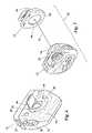
- FIG. 1is a perspective view of a portable exercise device in a retracted position.
- FIG. 2is a perspective view of the portable exercise device of FIG. 1 in an extended position.
- FIG. 3is a side cross-sectional view of the portable exercise device of FIG. 1 taken along line 3 — 3 of FIG. 1 .
- FIG. 4is a rear perspective view of the display module which forms a part of the portable exercise device shown in FIG. 1 .
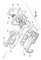
- FIG. 5is an exploded perspective view of the attachment module which forms a part of the portable exercise device shown in FIG. 1 .
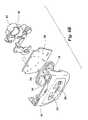
- FIGS. 6A and 6Bare an exploded perspective view of the portable exercise device of FIG. 1 .
- FIG. 7is a perspective view of an alternate embodiment of the device.
- Portable exercise device 10is made up of a display module 12 and an attachment module 14 .
- Display module 12is made up of the front cabinet 16 , a rear cabinet 18 and a top cover 20 .
- Top cover 20defines a window 22 for displaying information to a user.
- a first button 24is accessible through the top cover 20 .
- First button 24may be used to activate a light for illuminating information displayed through window 22 .
- a second button 26is preferably provided, which is also accessible through top cover 20 .
- Second button 26may be used to change information displayed through window 22 .
- An LCD display 28( FIGS. 1 , 3 and 6 A) is located beneath the top cover 20 for displaying information through the window 22 .
- Front cabinet 16defines a plurality of holes 30 therein ( FIGS. 3 and 6B ).
- a front keypad 32( FIG. 6B ) is positioned inside display module 12 behind the front cabinet 16 .
- Front keypad 32includes a plurality of keys 34 that protrude through the holes 30 in the front cabinet 16 .
- Rubber pads 36are located on each side of the display module 12 . Rubber pads 36 are preferably positioned in an interface between the front cabinet 16 and the rear cabinet 18 .
- a mounting plate 38( FIGS. 3 and 6B ) is preferably located within the display module 12 .
- An actuator assembly 40( FIG. 6B ) is affixed to rear side of the mounting plate 38 .
- a battery receptacle 42( FIG. 6B ) is preferably attached to the actuator assembly 40 .
- Rear cabinet 18has a battery door 44 ( FIG. 4 ) formed therein to provide access to the battery receptacle 42 .
- the rear cabinet 18further defines a recessed area 46 ( FIGS. 3 and 4 ), a first housing line orifice 48 and a second housing line orifice 50 ( FIG. 4 ) therein.
- attachment module 14is made up of a spool cover 52 and a clip holder 54 .
- Spool cover 52defines a protrusion 56 ( FIGS. 2 and 6A ) having an outer surface that engages in mating relationship with the recessed area 46 of the rear cabinet 18 .
- Spool cover 52has an inner surface that defines an axle member 58 ( FIG. 5 ).
- a first channel 60extends radially outward from axle member 58 on an inner surface of the spool cover 52 .
- Spool cover 52also defines a second channel 62 that extends radially outward from axle member 58 .
- Spool cover 52further defines a first attachment module line orifice 64 ( FIG. 2 ) that communicates with an outer end of the first channel 60 and a second cable orifice 66 ( FIGS. 2 and 6A ) that communicates with an outer end of the second channel 62 .
- a spring member 68( FIGS. 3 , 5 and 6 A) is provided that engages an inside surface of the clip holder 54 .
- a spool 70( FIGS. 3 , 5 and 6 A) is located in the attachment module 14 between the spool cover 52 and the clip holder 54 .
- Spool 70is rotationally mounted on axle member 58 of spool cover 52 .
- Spool 70is rotationally biased in a first direction by spring member 68 .
- a metal washer 72( FIG. 5 ) is also mounted on axle member 58 and is located between the spool 70 and the spool cover 52 .
- a first cable 74( FIGS. 2 and 5 ) has a first end 76 ( FIG. 5 ) that is secured to the spool 70 .
- First cable 74passes through first channel 60 in spool cover 52 and out of first attachment module line orifice 64 .
- First cable 74further passes through first housing line orifice 48 in rear cabinet 18 for securing a second end of first cable 74 to the rear cabinet 18 .
- a second cable 80( FIGS. 2 , 5 and 6 A) has a first end 82 ( FIG. 6A ) that is secured to the spool 70 .
- Second cable 80passes through second channel 62 in spool cover 52 and out of second attachment module line orifice 66 .
- Second cable 80further passes through second housing line orifice 50 in rear cabinet 18 for securing a second end of second cable 80 to rear cabinet 18 .
- a pair of clip mounts 86( FIGS. 1 and 5 ) are provided on an outside surface of clip holder 54 .
- a shaft 88is located in receiving orifices defined by clip mounts 86 .
- a belt clip 90is pivotally mounted on shaft 88 .
- a clip spring 92is provided for biasing the belt clip 90 towards the clip holder 54 .
- FIG. 7An alternate embodiment of the invention may be seen in FIG. 7 wherein spool 70 is located within display module 12 .
- a single cable 74connects the display module 12 to the attachment module 14 .
- the display module 12is provided with a protrusion 56 for mating engagement with recess 46 , formed in attachment module 14 .
- the portable device 10may be attached to the waist of a user.
- the upper portion of belt clip 90may be depressed by the thumb of a wearer to separate the belt clip 90 from the clip holder 54 .
- a wearer's waist band or beltmay then be inserted between the belt clip 90 and the clip holder 54 .
- the belt clip 90may then released.
- the clip spring 92biases the belt clip 90 against the clip holder 54 to secure the portable exercise device 10 to the waist of a user.
- the display module 12may be separated from attachment module 14 so that display module 12 may be more easily manipulated and viewed by the wearer.
- a gripping surface on the display module 12is provided by rubber pads 36 .
- first cable 74 and second cable 80extend outwardly from first housing line orifice 48 and second housing line orifice 50 , respectively.
- first cable 74 and second cable 80are pulled through first attachment module line orifice 64 and second attachment module line orifice 66 as spool 70 unwinds the cables 74 , 80 .
- Spool 70unwinds the first cable 74 and second cable 80 simultaneously.
- the first cable 74is pulled through the first channel 60 formed in the spool cover 52 of the attachment module 14 .
- second cable 80passes through second channel 62 , which is formed in the spool cover 52 of the attachment module 14 .
- Protrusion 56is preferably provided on the spool cover 52 of attachment module 14 . Protrusion 56 is sized for mating engagement with recessed area 46 formed on a rear surface of rear cabinet 18 of display module 12 . Therefore, when the display module 12 is seated against attachment module 14 and held thereto by first cable 74 and second cable 80 , the display module 12 is substantially prevented from lateral movement relative to attachment module 14 .
- magnetsmay be installed in display module 12 and attachment module 14 to facilitate proper fitting of the modules when connected.
- four pairs of magnetsare arranged in or around recessed area 46 and protrusion 56 for mating engagement when display module 12 is seated against attachment module 14 .
- the addition of magnetsimproves the “feel” for the user when the display module 12 is parked against the attachment module 14 .
- the resulting portable deviceprovides advantages of being easily viewed by a wearer by permitting the display module to be moved and oriented in a manner desired by the wearer. Additionally, the benefits associated with a manipulatable display module 12 do not result in a configuration wherein the attachment module 14 and display module 12 may become separated from one another. Moreover, the biasing action of spring member 68 provides sufficient force to secure display module 12 to attachment module 14 so that the display module 12 and attachment module 14 function as a single unit when in a retracted condition as shown in FIG. 1 . Finally, the mating protrusion 56 and recessed area 46 prevent relative lateral movement between the display module 12 and attachment module 14 of the exercise device.
Landscapes
- Physics & Mathematics (AREA)
- Engineering & Computer Science (AREA)
- General Physics & Mathematics (AREA)
- Radar, Positioning & Navigation (AREA)
- Remote Sensing (AREA)
- Casings For Electric Apparatus (AREA)
Abstract
Description
Claims (14)
Priority Applications (2)
| Application Number | Priority Date | Filing Date | Title |
|---|---|---|---|
| US10/606,664US6961401B1 (en) | 2003-06-26 | 2003-06-26 | Retractable pedometer |
| US11/263,572US20060120503A1 (en) | 2003-06-26 | 2005-10-31 | Retractable pedometer |
Applications Claiming Priority (1)
| Application Number | Priority Date | Filing Date | Title |
|---|---|---|---|
| US10/606,664US6961401B1 (en) | 2003-06-26 | 2003-06-26 | Retractable pedometer |
Related Child Applications (1)
| Application Number | Title | Priority Date | Filing Date |
|---|---|---|---|
| US11/263,572ContinuationUS20060120503A1 (en) | 2003-06-26 | 2005-10-31 | Retractable pedometer |
Publications (1)
| Publication Number | Publication Date |
|---|---|
| US6961401B1true US6961401B1 (en) | 2005-11-01 |
Family
ID=35150840
Family Applications (2)
| Application Number | Title | Priority Date | Filing Date |
|---|---|---|---|
| US10/606,664Expired - Fee RelatedUS6961401B1 (en) | 2003-06-26 | 2003-06-26 | Retractable pedometer |
| US11/263,572AbandonedUS20060120503A1 (en) | 2003-06-26 | 2005-10-31 | Retractable pedometer |
Family Applications After (1)
| Application Number | Title | Priority Date | Filing Date |
|---|---|---|---|
| US11/263,572AbandonedUS20060120503A1 (en) | 2003-06-26 | 2005-10-31 | Retractable pedometer |
Country Status (1)
| Country | Link |
|---|---|
| US (2) | US6961401B1 (en) |
Cited By (20)
| Publication number | Priority date | Publication date | Assignee | Title |
|---|---|---|---|---|
| US20050011982A1 (en)* | 2003-04-01 | 2005-01-20 | Hammerhead Industries, Inc. | Tethering system for personal electronic devices |
| US20050139648A1 (en)* | 2003-12-25 | 2005-06-30 | Yung-Nien Chen | Vibration pickup |
| US20060120503A1 (en)* | 2003-06-26 | 2006-06-08 | Michael Nally | Retractable pedometer |
| USD531072S1 (en)* | 2006-02-10 | 2006-10-31 | Ariel Premium Supply Inc. | Pedometer with FM scan radio |
| USD543877S1 (en)* | 2006-07-10 | 2007-06-05 | Sun Coast Merchandise Corp. | Pedometer |
| USD615427S1 (en) | 2009-08-10 | 2010-05-11 | Ariel Premium Supply, Inc. | Pedometer |
| USD657702S1 (en) | 2011-02-24 | 2012-04-17 | Ariel Premium Supply, Inc. | Pedometer |
| US9786140B2 (en) | 2010-06-21 | 2017-10-10 | Mobile Tech, Inc. | Display for hand-held electronics |
| US9892604B2 (en) | 2016-04-15 | 2018-02-13 | Mobile Tech, Inc. | Gateway-based anti-theft security system and method |
| US10101770B2 (en) | 2016-07-29 | 2018-10-16 | Mobile Tech, Inc. | Docking system for portable computing device in an enclosure |
| US10198035B2 (en) | 2012-12-05 | 2019-02-05 | Mobile Tech, Inc. | Docking station for tablet device |
| US10251144B2 (en) | 2015-12-03 | 2019-04-02 | Mobile Tech, Inc. | Location tracking of products and product display assemblies in a wirelessly connected environment |
| US10269202B2 (en) | 2001-12-27 | 2019-04-23 | Mobile Tech, Inc. | Intelligent key system |
| US10373456B2 (en) | 2009-01-10 | 2019-08-06 | Mobile Tech, Inc. | Display for hand-held electronics |
| US10517056B2 (en) | 2015-12-03 | 2019-12-24 | Mobile Tech, Inc. | Electronically connected environment |
| US10593443B1 (en) | 2019-01-24 | 2020-03-17 | Mobile Tech, Inc. | Motion sensing cable for intelligent charging of devices |
| US10728868B2 (en) | 2015-12-03 | 2020-07-28 | Mobile Tech, Inc. | Remote monitoring and control over wireless nodes in a wirelessly connected environment |
| US11109335B2 (en) | 2015-12-03 | 2021-08-31 | Mobile Tech, Inc. | Wirelessly connected hybrid environment of different types of wireless nodes |
| US11344140B2 (en) | 2009-01-10 | 2022-05-31 | Mobile Tech, Inc. | Display for hand-held electronics |
| US11540350B2 (en) | 2018-10-25 | 2022-12-27 | Mobile Tech, Inc. | Proxy nodes for expanding the functionality of nodes in a wirelessly connected environment |
Families Citing this family (2)
| Publication number | Priority date | Publication date | Assignee | Title |
|---|---|---|---|---|
| USD593884S1 (en)* | 2007-10-19 | 2009-06-09 | Shenzhen Double Power Electronics Co., Ltd | Pedometer |
| US20090183691A1 (en)* | 2008-11-07 | 2009-07-23 | Andre Hassan | Lcd equipped and glow-in-the-dark dog leash |
Citations (12)
| Publication number | Priority date | Publication date | Assignee | Title |
|---|---|---|---|---|
| US1567783A (en) | 1925-04-03 | 1925-12-29 | Best William | Key-chain reel |
| US4126024A (en) | 1977-03-24 | 1978-11-21 | Timmons David R | Bicycle cable lock |
| US4715235A (en) | 1985-03-04 | 1987-12-29 | Asahi Kasei Kogyo Kabushiki Kaisha | Deformation sensitive electroconductive knitted or woven fabric and deformation sensitive electroconductive device comprising the same |
| US4756171A (en) | 1987-03-02 | 1988-07-12 | Homar Paul F | Luggage lock system |
| US4970882A (en) | 1989-11-22 | 1990-11-20 | Arrendondo Ralph A | Bicycle cable lock |
| US5117444A (en)* | 1990-07-30 | 1992-05-26 | W. Ron Sutton | High accuracy pedometer and calibration method |
| US5718100A (en) | 1996-08-21 | 1998-02-17 | Petty; Roy L. | Package wrapping apparatus and method |
| US5938137A (en)* | 1998-06-22 | 1999-08-17 | Poulson; Harold T. | Cellular phone leash |
| US6254249B1 (en)* | 1999-02-26 | 2001-07-03 | Seong-Soo Kim | Cellular phone capable of reading memorandum in a dark area |
| US20010022828A1 (en) | 1998-10-28 | 2001-09-20 | Nathan Pyles | Pedometer |
| US6752946B2 (en)* | 1996-09-27 | 2004-06-22 | Nissha Printing Co., Ltd. | Cellular phone top cover and method of manufacturing the cellular phone top cover |
| US6785522B2 (en)* | 1999-12-30 | 2004-08-31 | Samsung Electronics Co., Ltd. | Method for changing timbre during conversation in cellular phone |
Family Cites Families (10)
| Publication number | Priority date | Publication date | Assignee | Title |
|---|---|---|---|---|
| US4946010A (en)* | 1989-03-30 | 1990-08-07 | Dibono Peter A | Telephone cord retraction device |
| US6573224B2 (en)* | 1997-01-03 | 2003-06-03 | Bardahl Manufacturing Corporation | Two-cycle engine lubricant composition comprising an ester copolymer and a diester |
| US5936137A (en)* | 1997-06-06 | 1999-08-10 | The United States Of America As Represented By The Secretary Of Commerce | Process for destroying halogenated compounds |
| US20010032868A1 (en)* | 2000-04-10 | 2001-10-25 | Callahan David E. | CB microphone leash |
| FI112422B (en)* | 2000-04-28 | 2003-11-28 | Nokia Corp | Telescope structure for a telephone set |
| US6364237B1 (en)* | 2000-06-16 | 2002-04-02 | Perfect Promotional Products | Retractable badgeholder with spinning display |
| US6591461B2 (en)* | 2001-04-13 | 2003-07-15 | John A. Salentine | Connector with strain relief |
| JP5073136B2 (en)* | 2001-08-24 | 2012-11-14 | ルネサスエレクトロニクス株式会社 | Semiconductor device |
| US20030093931A1 (en)* | 2001-11-19 | 2003-05-22 | Cuff John L. | Card holder |
| US6961401B1 (en)* | 2003-06-26 | 2005-11-01 | Sportcraft, Ltd. | Retractable pedometer |
- 2003
- 2003-06-26USUS10/606,664patent/US6961401B1/ennot_activeExpired - Fee Related
- 2005
- 2005-10-31USUS11/263,572patent/US20060120503A1/ennot_activeAbandoned
Patent Citations (12)
| Publication number | Priority date | Publication date | Assignee | Title |
|---|---|---|---|---|
| US1567783A (en) | 1925-04-03 | 1925-12-29 | Best William | Key-chain reel |
| US4126024A (en) | 1977-03-24 | 1978-11-21 | Timmons David R | Bicycle cable lock |
| US4715235A (en) | 1985-03-04 | 1987-12-29 | Asahi Kasei Kogyo Kabushiki Kaisha | Deformation sensitive electroconductive knitted or woven fabric and deformation sensitive electroconductive device comprising the same |
| US4756171A (en) | 1987-03-02 | 1988-07-12 | Homar Paul F | Luggage lock system |
| US4970882A (en) | 1989-11-22 | 1990-11-20 | Arrendondo Ralph A | Bicycle cable lock |
| US5117444A (en)* | 1990-07-30 | 1992-05-26 | W. Ron Sutton | High accuracy pedometer and calibration method |
| US5718100A (en) | 1996-08-21 | 1998-02-17 | Petty; Roy L. | Package wrapping apparatus and method |
| US6752946B2 (en)* | 1996-09-27 | 2004-06-22 | Nissha Printing Co., Ltd. | Cellular phone top cover and method of manufacturing the cellular phone top cover |
| US5938137A (en)* | 1998-06-22 | 1999-08-17 | Poulson; Harold T. | Cellular phone leash |
| US20010022828A1 (en) | 1998-10-28 | 2001-09-20 | Nathan Pyles | Pedometer |
| US6254249B1 (en)* | 1999-02-26 | 2001-07-03 | Seong-Soo Kim | Cellular phone capable of reading memorandum in a dark area |
| US6785522B2 (en)* | 1999-12-30 | 2004-08-31 | Samsung Electronics Co., Ltd. | Method for changing timbre during conversation in cellular phone |
Cited By (40)
| Publication number | Priority date | Publication date | Assignee | Title |
|---|---|---|---|---|
| US10269202B2 (en) | 2001-12-27 | 2019-04-23 | Mobile Tech, Inc. | Intelligent key system |
| US10984625B2 (en) | 2001-12-27 | 2021-04-20 | Mobile Tech, Inc. | Intelligent key system |
| US10453291B2 (en) | 2001-12-27 | 2019-10-22 | Mobile Tech, Inc. | Intelligent key system |
| US20050011982A1 (en)* | 2003-04-01 | 2005-01-20 | Hammerhead Industries, Inc. | Tethering system for personal electronic devices |
| US20060120503A1 (en)* | 2003-06-26 | 2006-06-08 | Michael Nally | Retractable pedometer |
| US20050139648A1 (en)* | 2003-12-25 | 2005-06-30 | Yung-Nien Chen | Vibration pickup |
| USD531072S1 (en)* | 2006-02-10 | 2006-10-31 | Ariel Premium Supply Inc. | Pedometer with FM scan radio |
| USD543877S1 (en)* | 2006-07-10 | 2007-06-05 | Sun Coast Merchandise Corp. | Pedometer |
| US10373456B2 (en) | 2009-01-10 | 2019-08-06 | Mobile Tech, Inc. | Display for hand-held electronics |
| US10026281B2 (en) | 2009-01-10 | 2018-07-17 | Mobile Tech, Inc. | Display for hand-held electronics |
| US11344140B2 (en) | 2009-01-10 | 2022-05-31 | Mobile Tech, Inc. | Display for hand-held electronics |
| US10977914B2 (en) | 2009-01-10 | 2021-04-13 | Mobile Tech, Inc. | Display for hand-held electronics |
| USD615427S1 (en) | 2009-08-10 | 2010-05-11 | Ariel Premium Supply, Inc. | Pedometer |
| US10083583B2 (en) | 2010-06-21 | 2018-09-25 | Mobile Tech, Inc. | Display for hand-held electronics |
| US10217338B2 (en) | 2010-06-21 | 2019-02-26 | Mobile Tech, Inc. | Display for hand-held electronics |
| US10861300B2 (en) | 2010-06-21 | 2020-12-08 | Mobile Tech, Inc. | Display for hand-held electronics |
| US9786140B2 (en) | 2010-06-21 | 2017-10-10 | Mobile Tech, Inc. | Display for hand-held electronics |
| USD657702S1 (en) | 2011-02-24 | 2012-04-17 | Ariel Premium Supply, Inc. | Pedometer |
| US10198035B2 (en) | 2012-12-05 | 2019-02-05 | Mobile Tech, Inc. | Docking station for tablet device |
| US10198036B2 (en) | 2012-12-05 | 2019-02-05 | Mobile Tech, Inc. | Docking station for tablet device |
| US10782735B2 (en) | 2012-12-05 | 2020-09-22 | Mobile Tech, Inc. | Docking station for tablet device |
| US10524220B2 (en) | 2015-12-03 | 2019-12-31 | Mobile Tech, Inc. | Location tracking of products and product display assemblies in a wirelessly connected environment |
| US10251144B2 (en) | 2015-12-03 | 2019-04-02 | Mobile Tech, Inc. | Location tracking of products and product display assemblies in a wirelessly connected environment |
| US11109335B2 (en) | 2015-12-03 | 2021-08-31 | Mobile Tech, Inc. | Wirelessly connected hybrid environment of different types of wireless nodes |
| US10667227B2 (en) | 2015-12-03 | 2020-05-26 | Mobile Tech, Inc. | Electronically connected environment |
| US10674466B2 (en) | 2015-12-03 | 2020-06-02 | Mobile Tech, Inc. | Location tracking of products and product display assemblies in a wirelessly connected environment |
| US10728868B2 (en) | 2015-12-03 | 2020-07-28 | Mobile Tech, Inc. | Remote monitoring and control over wireless nodes in a wirelessly connected environment |
| US10517056B2 (en) | 2015-12-03 | 2019-12-24 | Mobile Tech, Inc. | Electronically connected environment |
| US9959432B2 (en) | 2016-04-15 | 2018-05-01 | Mobile Tech, Inc. | Authorization control for an anti-theft security system |
| US10540872B2 (en) | 2016-04-15 | 2020-01-21 | Mobile Tech, Inc. | Gateway-based anti-theft security system and method |
| US11315398B2 (en) | 2016-04-15 | 2022-04-26 | Mobile Tech, Inc. | Gateway-based anti-theft security system and method |
| US10776473B2 (en) | 2016-04-15 | 2020-09-15 | Mobile Tech, Inc. | Authorization control for an anti-theft security system |
| US10157522B2 (en) | 2016-04-15 | 2018-12-18 | Mobile Tech, Inc. | Authorization control for an anti-theft security system |
| US9892604B2 (en) | 2016-04-15 | 2018-02-13 | Mobile Tech, Inc. | Gateway-based anti-theft security system and method |
| US10754381B2 (en) | 2016-07-29 | 2020-08-25 | Mobile Tech, Inc. | Docking system for portable computing device |
| US10281955B2 (en) | 2016-07-29 | 2019-05-07 | Mobile Tech, Inc. | Docking system for portable computing device |
| US10101770B2 (en) | 2016-07-29 | 2018-10-16 | Mobile Tech, Inc. | Docking system for portable computing device in an enclosure |
| US11540350B2 (en) | 2018-10-25 | 2022-12-27 | Mobile Tech, Inc. | Proxy nodes for expanding the functionality of nodes in a wirelessly connected environment |
| US10614682B1 (en) | 2019-01-24 | 2020-04-07 | Mobile Tech, Inc. | Motion sensing cable for tracking customer interaction with devices |
| US10593443B1 (en) | 2019-01-24 | 2020-03-17 | Mobile Tech, Inc. | Motion sensing cable for intelligent charging of devices |
Also Published As
| Publication number | Publication date |
|---|---|
| US20060120503A1 (en) | 2006-06-08 |
Similar Documents
| Publication | Publication Date | Title |
|---|---|---|
| US6961401B1 (en) | Retractable pedometer | |
| US12164180B2 (en) | Eyewear supporting distributed and embedded electronic components | |
| US6217482B1 (en) | Entertainment and exercise device | |
| US4766611A (en) | Glove and watch | |
| US8616422B2 (en) | Cantilevered snap fit case | |
| US7543934B2 (en) | Eyeglasses with activity monitoring and acoustic dampening | |
| US20190336020A1 (en) | Equipment for monitoring health conditions of monitored persons | |
| US9474953B1 (en) | System, method and processor-readable medium for wirelessly tracking basketball shots | |
| US6881273B1 (en) | Eyewear cleaning device | |
| US20120322587A1 (en) | Hoop tracker | |
| US7699198B2 (en) | Attachment mechanism for use with a portable electronic device, and method of manufacturing same | |
| EP2619749A1 (en) | Head-mounted peripheral vision display systems and methods | |
| US5964385A (en) | Cane retrieval device | |
| US11179621B2 (en) | Athletic timing device | |
| US11659917B2 (en) | Apparatus with self-retracting elastomeric support band | |
| JP4187261B2 (en) | Mobile information terminal equipment | |
| KR20050005798A (en) | Extendable and retractable shoulder strap for golf bags | |
| CN215995446U (en) | Rope skipping handle of anticreep prevents falling PPG photoelectric sensing real-time supervision rhythm of heart | |
| CN222561933U (en) | Wear-proof device of watch display screen | |
| KR20150066155A (en) | Distance Measuring the Flight Distance for golf | |
| CN222089713U (en) | Clamping assembly and wearable sound box | |
| CN213638096U (en) | Multifunctional portable sound equipment | |
| KR20250062087A (en) | Bag for golf rounding | |
| KR200370039Y1 (en) | Pedometer having band | |
| KR200405083Y1 (en) | Band pedometer |
Legal Events
| Date | Code | Title | Description |
|---|---|---|---|
| AS | Assignment | Owner name:MERRILL LYNCH BUSINESS FINANCIAL, ILLINOIS Free format text:SECURITY INTEREST;ASSIGNOR:SPORTCRAFT, LTD.;REEL/FRAME:014588/0200 Effective date:20031001 | |
| AS | Assignment | Owner name:SPORTCRAFT, LTD., NEW JERSEY Free format text:ASSIGNMENT OF ASSIGNORS INTEREST;ASSIGNORS:NALLY, MICHAEL;SCHULZ, MARK;REEL/FRAME:014677/0603;SIGNING DATES FROM 20030812 TO 20030813 | |
| AS | Assignment | Owner name:WELLS FARGO FOOTHILL, INC., AS COLLATERAL AGENT, M Free format text:SECURITY AGREEMENT;ASSIGNORS:SPORTCRAFT, LTD.;CLASSIC SPORT COMPANIES, INC.;REEL/FRAME:019943/0526 Effective date:20070928 | |
| AS | Assignment | Owner name:GUGGENHEIM CORPORATE FUNDING, LLC, NEW YORK Free format text:SECURITY AGREEMENT;ASSIGNORS:SPORTCRAFT, LTD.;CLASSIC SPORT COMPANIES, INC.;REEL/FRAME:019965/0421 Effective date:20070928 | |
| AS | Assignment | Owner name:SPORTCRAFT, LTD., NEW JERSEY Free format text:RELEASE OF PATENT SECURITY AGREEMENT;ASSIGNOR:MERRILL LYNCH BUSINESS FINANCIAL SERVICES INC. ACTING THROUGH ITS DIVISION MERRILL LYNCH CAPITAL;REEL/FRAME:019984/0073 Effective date:20070928 | |
| REMI | Maintenance fee reminder mailed | ||
| LAPS | Lapse for failure to pay maintenance fees | ||
| STCH | Information on status: patent discontinuation | Free format text:PATENT EXPIRED DUE TO NONPAYMENT OF MAINTENANCE FEES UNDER 37 CFR 1.362 | |
| FP | Expired due to failure to pay maintenance fee | Effective date:20091101 | |
| AS | Assignment | Owner name:CLASSIC SPORT COMPANIES, INC., NEW JERSEY Free format text:RELEASE BY SECURED PARTY;ASSIGNOR:WELLS FARGO CAPITAL FINANCE, INC., AS COLLATERAL AGENT;REEL/FRAME:025441/0295 Effective date:20101203 Owner name:SPORTCRAFT, LTD., NEW JERSEY Free format text:RELEASE BY SECURED PARTY;ASSIGNOR:WELLS FARGO CAPITAL FINANCE, INC., AS COLLATERAL AGENT;REEL/FRAME:025441/0295 Effective date:20101203 |