US6960854B2 - Centrifugal turbine for breathing-aid devices - Google Patents
Centrifugal turbine for breathing-aid devicesDownload PDFInfo
- Publication number
- US6960854B2 US6960854B2US10/496,876US49687604AUS6960854B2US 6960854 B2US6960854 B2US 6960854B2US 49687604 AUS49687604 AUS 49687604AUS 6960854 B2US6960854 B2US 6960854B2
- Authority
- US
- United States
- Prior art keywords
- turbine
- stator
- wheel
- rotor
- motor
- Prior art date
- Legal status (The legal status is an assumption and is not a legal conclusion. Google has not performed a legal analysis and makes no representation as to the accuracy of the status listed.)
- Expired - Lifetime
Links
- 230000006835compressionEffects0.000claimsabstractdescription21
- 238000007906compressionMethods0.000claimsabstractdescription21
- 230000002093peripheral effectEffects0.000claimsdescription3
- 238000004804windingMethods0.000claimsdescription2
- 230000000241respiratory effectEffects0.000description10
- BGPVFRJUHWVFKM-UHFFFAOYSA-NN1=C2C=CC=CC2=[N+]([O-])C1(CC1)CCC21N=C1C=CC=CC1=[N+]2[O-]Chemical compoundN1=C2C=CC=CC2=[N+]([O-])C1(CC1)CCC21N=C1C=CC=CC1=[N+]2[O-]BGPVFRJUHWVFKM-UHFFFAOYSA-N0.000description6
- 208000037265diseases, disorders, signs and symptomsDiseases0.000description3
- 208000035475disorderDiseases0.000description3
- 208000008784apneaDiseases0.000description2
- 238000004026adhesive bondingMethods0.000description1
- 238000009434installationMethods0.000description1
- 238000004519manufacturing processMethods0.000description1
- 230000001105regulatory effectEffects0.000description1
- 230000029058respiratory gaseous exchangeEffects0.000description1
- 201000002859sleep apneaDiseases0.000description1
- 230000036578sleeping timeEffects0.000description1
Images


Classifications
- F—MECHANICAL ENGINEERING; LIGHTING; HEATING; WEAPONS; BLASTING
- F04—POSITIVE - DISPLACEMENT MACHINES FOR LIQUIDS; PUMPS FOR LIQUIDS OR ELASTIC FLUIDS
- F04D—NON-POSITIVE-DISPLACEMENT PUMPS
- F04D29/00—Details, component parts, or accessories
- F04D29/26—Rotors specially for elastic fluids
- F04D29/28—Rotors specially for elastic fluids for centrifugal or helico-centrifugal pumps for radial-flow or helico-centrifugal pumps
- F04D29/30—Vanes
- F—MECHANICAL ENGINEERING; LIGHTING; HEATING; WEAPONS; BLASTING
- F04—POSITIVE - DISPLACEMENT MACHINES FOR LIQUIDS; PUMPS FOR LIQUIDS OR ELASTIC FLUIDS
- F04D—NON-POSITIVE-DISPLACEMENT PUMPS
- F04D17/00—Radial-flow pumps, e.g. centrifugal pumps; Helico-centrifugal pumps
- F04D17/06—Helico-centrifugal pumps
- F—MECHANICAL ENGINEERING; LIGHTING; HEATING; WEAPONS; BLASTING
- F04—POSITIVE - DISPLACEMENT MACHINES FOR LIQUIDS; PUMPS FOR LIQUIDS OR ELASTIC FLUIDS
- F04D—NON-POSITIVE-DISPLACEMENT PUMPS
- F04D25/00—Pumping installations or systems
- F04D25/02—Units comprising pumps and their driving means
- F04D25/06—Units comprising pumps and their driving means the pump being electrically driven
- F04D25/0606—Units comprising pumps and their driving means the pump being electrically driven the electric motor being specially adapted for integration in the pump
- F—MECHANICAL ENGINEERING; LIGHTING; HEATING; WEAPONS; BLASTING
- F04—POSITIVE - DISPLACEMENT MACHINES FOR LIQUIDS; PUMPS FOR LIQUIDS OR ELASTIC FLUIDS
- F04D—NON-POSITIVE-DISPLACEMENT PUMPS
- F04D29/00—Details, component parts, or accessories
- F04D29/26—Rotors specially for elastic fluids
- F04D29/28—Rotors specially for elastic fluids for centrifugal or helico-centrifugal pumps for radial-flow or helico-centrifugal pumps
- F04D29/281—Rotors specially for elastic fluids for centrifugal or helico-centrifugal pumps for radial-flow or helico-centrifugal pumps for fans or blowers
Definitions
- the inventionconcerns motorised turbines intended for the production of a continuous flow of air and more particularly the turbines equipping respiratory assistance devices.
- These respiratory assistance devicescan be provided for treating sleep apnoea disorders.
- a respiratory maskapplied over the nose and/or mouth of a user while he is asleep, and a case supplying pressurised air to this mask so as to prevent the user entering an apnoea phase.
- the known respiratory assistance devicesIn order to supply the pressurised air to the respiratory mask, the known respiratory assistance devices generally propose to deliver a continuous flow, regulated or not, of air by means of a turbine driven rotationally by an electric motor. This air flow is conveyed by a tube into the mask which furthermore comprises a calibrated leakage aperture, the desired pressurisation thus being maintained.
- the patent FR 2 663 547describes such a device.
- This documentrefers to an installation for continuous supply of respiratory gas pressurisation comprising a respiratory mask with calibrated aperture and a pressurised gas supply unit connected by a tube to the mask.
- a centrifugal type turbine operated by an electric motoris provided for generating a discharge of air.
- a respiratory assistance deviceis intended, the majority of the time, for use at home. It must therefore be easily transportable and not very bulky in order to be placed at the foot of the bed of the patient or on a bedside table.
- the aim of the inventionis to overcome these drawbacks of the prior art by providing a more compact motor/turbine assembly, allowing the implementation of respiratory assistance devices of reduced size.
- the object of the inventionis an electric turbine comprising a turbine rotor, a turbine stator, an electric motor member intended to drive the rotor rotationally with respect to the stator, said turbine having the following characteristics:
- One out of the motor stator or rotorcan be a permanent magnet, just as at least one out of the motor stator or rotor can be a toric winding.
- the turbine rotor shaftcan be mounted on at least one bearing coaxial with the annular intake duct, and on at least one bearing situated in the motor housing.
- the stator body of the turbinecan comprise two parts cooperating with one another and delimiting the toric compression chamber.
- the bladescan be carried by an overmoulded wheel forming a sleeve on the turbine rotor shaft, said sleeve possibly comprising a shoulder intended for the axial support of the motor rotor.
- Said wheel carrying the bladescan also be truncated cone-shaped.
- These blades carried by the wheelcan be formed from a flat wall fixed perpendicular to the surface of the wheel, this wall having a generally trapezoidal shape and having a greater height in the central part of the wheel than in its peripheral part.
- certain of said bladescan comprise, in their part disposed in the central part of the wheel, a protruding tip intended to follow the shape of the annular intake duct.
- one blade out of twocomprises such a protruding tip.
- certain of said bladesform an angle of 5 to 60 degrees with the radius of the wheel passing through the end of the blade, at the periphery of the wheel.
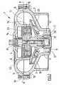
- FIG. 1is a perspective view, in diametral section, of a turbine according to the invention
- FIG. 2is a front view, in diametral section, of the turbine of FIG. 1 ;
- FIG. 3is an exploded view of the turbine of FIG. 1 ;
- FIG. 4is a side view of the wheel of the turbine of FIG. 1 ;
- FIG. 5is a perspective view of the wheel of FIG. 4 .
- the turbine 1 depicted in FIGS. 1 , 2 and 3comprises an upper body 2 assembled with a lower body 3 , defining between them a volume in which there are positioned a vertical shaft 4 mounted on two roller bearings 13 , 14 , a toric magnet 5 , a toric coil 6 and a blade-carrying wheel 7 .
- the upper body 2is dish-shaped, comprising an internal annular skirt 16 (on the side of the lower body 3 ) coaxial with said dish and intended to form a motor housing, and a semi-toric wall 22 situated on the periphery of the dish.
- the lower body 3has a hollow shape delimited by a first annular wall 17 connected to a second conical wall 18 widening out towards the top and itself connected to a connecting wall 19 with an arc of a circle cross-section.
- the annular wall 17surrounds a hub 20 intended for mounting the roller bearing 13 , said hub 20 being positioned in a rigid manner coaxially with the annular wall 17 by three fixed blades 21 connecting the inside of the annular wall to the outside of the hub and disposed at 120° to one another.
- the upper 2 and lower 3 bodiesare formed in order to constitute, once assembled, an internal volume characteristic of a centrifugal turbine; in particular, the walls 19 , 22 of the upper 2 and lower 3 bodies delimit a toric compression chamber 12 .
- This chamber 12is open to the outside by means of a substantially cylindrical tangential duct 25 (towards the mask of the user) whose longitudinal axis is horizontal.
- the assembly of the upper 2 and lower 3 bodiesis implemented in a sealed manner at a joint face 8 . Studs 9 emerging from the lower body 3 at the joint face 8 are arranged in order to enter corresponding apertures formed in the upper body 2 , thus providing the stringent positioning of one body with respect to the other.
- the holding of the assemblyis implemented by means of a series of screws 10 disposed regularly on the perimeter of the joint face.
- the lower body 3comprises a hub 20 placed coaxially inside the annular wall 17 and fitted so that a first roller bearing 13 intended to support the vertical shaft 4 fits therein in order to be rigidly fixed therein.
- the upper body 2comprises a similar housing delimited by the skirt 16 and intended to receive a second roller bearing 14 supporting the vertical shaft 4 but, unlike the housing provided for the first roller bearing 13 , this housing is fitted in order to immobilise the second roller bearing 14 in its radial directions and to leave it free as regards translational motion in the vertical direction.
- a spring 15is provided inside the housing of the second roller bearing 14 and exerts a force between the latter and the upper body 2 so as to maintain a pressure downwards on the roller bearing 14 .
- the vertical shaft 4on the ends of which the two roller bearings 13 , 14 are mounted, is therefore positioned between the upper 2 and lower 3 bodies so as to be coaxial with the annular intake duct 11 and the toric compression chamber 12 formed by the assembly of the upper 2 and lower 3 bodies.
- the blade-carrying wheel 7is also mounted on the vertical shaft 4 so as to be driven rotationally therewith. It can be for example overmoulded, glued or force-fitted on the shaft 4 .
- the blade-carrying wheel 7has a substantially conical shape allowing it to follow the internal shape of the annular 17 and conical 18 walls of the lower body 3 , the blades being disposed on the wheel 7 so as to drive the air in order to make it circulate between the volume delimited by said annular wall 17 and the toric compression chamber 12 , during the rotation of the vertical shaft 4 .
- annular skirt 16receives a horizontal plate 23 rigidly fixed to its internal wall, these two elements delimiting the previously described motor housing.
- the motor housingis intended to receive the toric coil 6 and keep it fixed with respect to said body 2 .
- This housingis disposed so that the coil 6 , when it is in place by gluing or fitting, is positioned as follows:
- the vertical shaft 7also carries the toric magnet 5 rigidly fixed and positioned as follows:
- the toric magnet 5can be directly fitted tight or glued on the vertical shaft 4 or else, as depicted in FIGS. 1 to 3 , the blade-carrying wheel 7 can be fitted tight or be glued on said shaft 4 by encasing it, the magnet 5 then being fitted tight or glued on this casing.
- the volume defined by the upper 2 and lower 3 bodies and by the wheel 7comprises an annular intake duct 11 open to the outside, coaxial with the vertical shaft 4 and delimited by the inside of the annular wall 17 and the external wall of the hub 20 .
- This annular intake duct 11communicates over its entire circumference with a compression duct 24 delimited by the inside of the conical wall 18 and the face of the blade-carrying wheel 7 .
- This compression duct 24is therefore a truncated cone-shaped volume delimited by two coaxial cones widening out from the intake duct 11 .
- the compression duct 24is itself connected over its entire circumference to the aforementioned toric compression chamber 12 .
- This toric compression chamber 12is delimited by the wall 22 and the annular projection of the upper body 2 , and by the wall 19 of the lower body 3 , these elements being arranged in order to constitute a toric internal volume comprising a circular slot forming an annular opening allowing communication with the compression duct 24 .
- the blades 26 , 27act on the air mainly at the level of the compression duct 24 and also partly at the level of the annular intake duct 11 .
- a first type of blade 26is formed from a flat wall fixed perpendicular to the surface of the wheel, this wall having a generally trapezoidal shape and having a greater height in the central part of the wheel 7 than in its peripheral part.
- a second type of blade 27is similar to the first type 26 but is longer so as to go further into the central part of the wheel 7 . Moreover, the part of the blade disposed in this central part of the wheel 7 has a protruding tip intended to follow the shape of the junction between the intake duct 11 and the compression duct 24 .
- These two types of bladeare furthermore disposed so as to form an angle of 5 to 60 degrees with the radius of the wheel 7 passing through the end of the blade, at the periphery of the wheel 7 , each type of blade possibly being disposed with a different angle from the other type.
Landscapes
- Engineering & Computer Science (AREA)
- Mechanical Engineering (AREA)
- General Engineering & Computer Science (AREA)
- Structures Of Non-Positive Displacement Pumps (AREA)
- Connection Of Motors, Electrical Generators, Mechanical Devices, And The Like (AREA)
- Turbine Rotor Nozzle Sealing (AREA)
- Centrifugal Separators (AREA)
Abstract
Description
This is a U.S. national phase of PCT/FR02/03846 filed Nov. 8, 2002, claiming priority from FR 01/15314 filed Nov. 27, 2001.
The invention concerns motorised turbines intended for the production of a continuous flow of air and more particularly the turbines equipping respiratory assistance devices.
These respiratory assistance devices can be provided for treating sleep apnoea disorders.
Patients suffering from these disorders are liable, during their sleeping time, to pass through phases of apnoea during which they stop breathing, thus causing them to wake up.
To remedy these disorders, there exist devices comprising a respiratory mask applied over the nose and/or mouth of a user while he is asleep, and a case supplying pressurised air to this mask so as to prevent the user entering an apnoea phase.
In order to supply the pressurised air to the respiratory mask, the known respiratory assistance devices generally propose to deliver a continuous flow, regulated or not, of air by means of a turbine driven rotationally by an electric motor. This air flow is conveyed by a tube into the mask which furthermore comprises a calibrated leakage aperture, the desired pressurisation thus being maintained.
For example, thepatent FR 2 663 547 describes such a device.
This document refers to an installation for continuous supply of respiratory gas pressurisation comprising a respiratory mask with calibrated aperture and a pressurised gas supply unit connected by a tube to the mask.
Within the pressurised gas supply unit, a centrifugal type turbine operated by an electric motor is provided for generating a discharge of air.
These devices of the prior art have a drawback as regards their size.
This is because a respiratory assistance device is intended, the majority of the time, for use at home. It must therefore be easily transportable and not very bulky in order to be placed at the foot of the bed of the patient or on a bedside table.
Earlier devices, with the passing of time, have been made increasingly compact following technological development. Nevertheless, it would seem that a limit has currently been reached as regards respiratory assistance devices comprising a conventional arrangement of their elements, as described in the aforementioned patent.
This is due partly to the fact that the motor/turbine assembly occupies a large space in the pressurised gas supply unit through its two-part structure.
The aim of the invention is to overcome these drawbacks of the prior art by providing a more compact motor/turbine assembly, allowing the implementation of respiratory assistance devices of reduced size.
To that end, the object of the invention is an electric turbine comprising a turbine rotor, a turbine stator, an electric motor member intended to drive the rotor rotationally with respect to the stator, said turbine having the following characteristics:
- the turbine stator comprises a stator body defining a generally toric compression chamber provided with an annular opening;
- the turbine rotor comprises a set of blades extending generally radially from a central air inlet formed by an annular intake duct to the annular opening of the compression chamber of the turbine stator, this set of blades being fixed to a shaft mounted coaxially able to rotate in the turbine stator body;
- the electric motor member comprises a toric motor stator housed and fixed in a motor housing of the turbine stator, at the centre of the toric compression chamber, and a motor rotor mounted and fixed on the turbine rotor shaft, axially opposite the motor stator.
One out of the motor stator or rotor can be a permanent magnet, just as at least one out of the motor stator or rotor can be a toric winding.
Furthermore, the turbine rotor shaft can be mounted on at least one bearing coaxial with the annular intake duct, and on at least one bearing situated in the motor housing.
The stator body of the turbine can comprise two parts cooperating with one another and delimiting the toric compression chamber.
The blades can be carried by an overmoulded wheel forming a sleeve on the turbine rotor shaft, said sleeve possibly comprising a shoulder intended for the axial support of the motor rotor.
Said wheel carrying the blades can also be truncated cone-shaped.
These blades carried by the wheel can be formed from a flat wall fixed perpendicular to the surface of the wheel, this wall having a generally trapezoidal shape and having a greater height in the central part of the wheel than in its peripheral part.
Moreover, certain of said blades can comprise, in their part disposed in the central part of the wheel, a protruding tip intended to follow the shape of the annular intake duct.
In one embodiment, one blade out of two comprises such a protruding tip.
According to another embodiment, certain of said blades form an angle of 5 to 60 degrees with the radius of the wheel passing through the end of the blade, at the periphery of the wheel.
Other particular features and advantages of the invention will emerge further in the following description relating to the accompanying drawings, given by way of a non-limiting example:
In the following description, the terms upper, lower, above, below, vertical and horizontal refer to the turbine in the position in which it is depicted inFIGS. 1 to3.
The turbine1 depicted inFIGS. 1 ,2 and3 comprises anupper body 2 assembled with alower body 3, defining between them a volume in which there are positioned avertical shaft 4 mounted on tworoller bearings toric magnet 5, atoric coil 6 and a blade-carryingwheel 7.
Theupper body 2 is dish-shaped, comprising an internal annular skirt16 (on the side of the lower body3) coaxial with said dish and intended to form a motor housing, and asemi-toric wall 22 situated on the periphery of the dish.
Thelower body 3 has a hollow shape delimited by a firstannular wall 17 connected to a secondconical wall 18 widening out towards the top and itself connected to a connectingwall 19 with an arc of a circle cross-section.
Theannular wall 17 surrounds ahub 20 intended for mounting the roller bearing13, saidhub 20 being positioned in a rigid manner coaxially with theannular wall 17 by threefixed blades 21 connecting the inside of the annular wall to the outside of the hub and disposed at 120° to one another.
The upper2 and lower3 bodies are formed in order to constitute, once assembled, an internal volume characteristic of a centrifugal turbine; in particular, thewalls toric compression chamber 12.
Thischamber 12 is open to the outside by means of a substantially cylindrical tangential duct25 (towards the mask of the user) whose longitudinal axis is horizontal.
The assembly of the upper2 and lower3 bodies is implemented in a sealed manner at ajoint face 8.Studs 9 emerging from thelower body 3 at thejoint face 8 are arranged in order to enter corresponding apertures formed in theupper body 2, thus providing the stringent positioning of one body with respect to the other. The holding of the assembly is implemented by means of a series ofscrews 10 disposed regularly on the perimeter of the joint face.
As mentioned previously, thelower body 3 comprises ahub 20 placed coaxially inside theannular wall 17 and fitted so that a first roller bearing13 intended to support thevertical shaft 4 fits therein in order to be rigidly fixed therein.
Similarly, theupper body 2 comprises a similar housing delimited by theskirt 16 and intended to receive a second roller bearing14 supporting thevertical shaft 4 but, unlike the housing provided for the first roller bearing13, this housing is fitted in order to immobilise the second roller bearing14 in its radial directions and to leave it free as regards translational motion in the vertical direction.
Aspring 15 is provided inside the housing of the second roller bearing14 and exerts a force between the latter and theupper body 2 so as to maintain a pressure downwards on the roller bearing14.
Thevertical shaft 4, on the ends of which the tworoller bearings annular intake duct 11 and thetoric compression chamber 12 formed by the assembly of the upper2 and lower3 bodies.
The blade-carryingwheel 7 is also mounted on thevertical shaft 4 so as to be driven rotationally therewith. It can be for example overmoulded, glued or force-fitted on theshaft 4.
In the implementation presented, the blade-carryingwheel 7 has a substantially conical shape allowing it to follow the internal shape of the annular17 and conical18 walls of thelower body 3, the blades being disposed on thewheel 7 so as to drive the air in order to make it circulate between the volume delimited by saidannular wall 17 and thetoric compression chamber 12, during the rotation of thevertical shaft 4.
Furthermore, theannular skirt 16 receives ahorizontal plate 23 rigidly fixed to its internal wall, these two elements delimiting the previously described motor housing.
The motor housing is intended to receive thetoric coil 6 and keep it fixed with respect to saidbody 2.
This housing is disposed so that thecoil 6, when it is in place by gluing or fitting, is positioned as follows:
- as regards positioning in the vertical direction: between the upper roller bearing14 of the
vertical shaft 4 and the blade-carryingwheel 7; - as regards positioning in the horizontal plane: the
coil 6 coaxially surrounds thevertical shaft 4.
- as regards positioning in the vertical direction: between the upper roller bearing14 of the
Thevertical shaft 7 also carries thetoric magnet 5 rigidly fixed and positioned as follows:
- as regards positioning in the vertical direction: substantially facing the
coil 6, surrounded thereby; - as regards positioning in the horizontal plane: the toric magnet coaxially surrounds the
vertical shaft 4.
- as regards positioning in the vertical direction: substantially facing the
Thetoric magnet 5 can be directly fitted tight or glued on thevertical shaft 4 or else, as depicted inFIGS. 1 to3, the blade-carryingwheel 7 can be fitted tight or be glued on saidshaft 4 by encasing it, themagnet 5 then being fitted tight or glued on this casing.
When thevertical shaft 4, thecoil 6 and themagnet 5 are in place in the volume formed by the assembled upper2 and lower3 bodies, these three elements are coaxial and theshaft 4 is capable of a rotation on its longitudinal axis, when themagnet 5 is rotated with respect to thecoil 6.
The volume defined by the upper2 and lower3 bodies and by thewheel 7 comprises anannular intake duct 11 open to the outside, coaxial with thevertical shaft 4 and delimited by the inside of theannular wall 17 and the external wall of thehub 20.
Thisannular intake duct 11 communicates over its entire circumference with acompression duct 24 delimited by the inside of theconical wall 18 and the face of the blade-carryingwheel 7. Thiscompression duct 24 is therefore a truncated cone-shaped volume delimited by two coaxial cones widening out from theintake duct 11.
Thecompression duct 24 is itself connected over its entire circumference to the aforementionedtoric compression chamber 12.
Thistoric compression chamber 12 is delimited by thewall 22 and the annular projection of theupper body 2, and by thewall 19 of thelower body 3, these elements being arranged in order to constitute a toric internal volume comprising a circular slot forming an annular opening allowing communication with thecompression duct 24.
When thewheel 7 is mounted in the turbine1, theblades compression duct 24 and also partly at the level of theannular intake duct 11.
This is because thewheel 7 carries two types ofblade
A first type ofblade 26 is formed from a flat wall fixed perpendicular to the surface of the wheel, this wall having a generally trapezoidal shape and having a greater height in the central part of thewheel 7 than in its peripheral part.
A second type ofblade 27 is similar to thefirst type 26 but is longer so as to go further into the central part of thewheel 7. Moreover, the part of the blade disposed in this central part of thewheel 7 has a protruding tip intended to follow the shape of the junction between theintake duct 11 and thecompression duct 24.
These two types of blade are furthermore disposed so as to form an angle of 5 to 60 degrees with the radius of thewheel 7 passing through the end of the blade, at the periphery of thewheel 7, each type of blade possibly being disposed with a different angle from the other type.
Claims (13)
1. An electric turbine (1) comprising a turbine rotor (4,7), a turbine stator (2,3), and electric motor member (5,6) intended to drive the rotor (4,7) rotationally with respect to the stator (2,3), wherein
the turbine stator (2,3) comprises a stator body defining a generally toric compression chamber (12) provided with an annular opening;
the turbine rotor (4,7) comprises a set of blades (26,27) extending generally radially from a central air inlet formed by an annular intake duct (11) to the annular opening of the compression chamber (12) of the turbine stator (2,3), this set of blades (26,27) being fixed to a shaft (4) mounted coaxially able to rotate in the turbine stator body;
the electric motor member (5,6) comprises a toric motor stator (6) housed and fixed in a motor housing (16,23) of the turbine stator (2,3), at the centre of the toric compression chamber (12), and a motor rotor (5) mounted and fixed on the turbine rotor shaft (4), axially opposite the motor stator (6).
2. A turbine according toclaim 1 , characterised in that one out of the motor stator (6) or rotor (5) is a permanent magnet.
3. A turbine according toclaim 1 , characterised in that at least one out of the motor stator (6) or rotor (5) is or are a toric winding.
4. A turbine according toclaim 1 , characterised in that the turbine rotor shaft (4) is mounted on at least one bearing (13,20) coaxial with the annular intake duct (11).
5. A turbine according toclaim 1 , characterised in that the turbine rotor shaft (4) is mounted on at least one bearing (14) situated in the motor housing.
6. A turbine according toclaim 1 , characterised in that the stator body (2,3) comprises two parts cooperating with one another and delimiting the toric compression chamber (12).
7. A turbine according toclaim 1 , characterised in that the blades (26,27) are carried by an overmoulded wheel (7) forming a sleeve on the turbine rotor shaft (4).
8. A turbine according toclaim 7 , characterised in that said sleeve comprises a shoulder intended for the axial support of the motor rotor (5).
9. A turbine according toclaim 1 , characterised in that the blades (26,27) are carried by a truncated cone-shaped wheel (7).
10. A turbine according toclaim 9 , characterised in that the blades (26,27) are formed from a flat wall fixed perpendicular to the surface of the wheel (7), this wall having a generally trapezoidal shape and having a greater height in the central part of the wheel (7) than in its peripheral part.
11. A turbine according toclaim 10 , characterised in that at least certain (27) of said blades (26,27) comprise, in their part disposed in the central part of the wheel, a protruding tip intended to follow the shape of the annular intake duct (11).
12. A turbine according toclaim 11 , characterised in that one blade out of two comprise, in their part disposed in the central part of the wheel (7), a protruding tip intended to follow the shape of the annular intake duct (11).
13. A turbine according toclaim 9 , characterised in that certain of said blades (26,27) form an angle of 5 to 60 degrees with the radius of the wheel (7) passing through the end of the blade, at the periphery of the wheel (7).
Applications Claiming Priority (3)
| Application Number | Priority Date | Filing Date | Title |
|---|---|---|---|
| FR0115314AFR2832770B1 (en) | 2001-11-27 | 2001-11-27 | CENTRIFUGAL TURBINE FOR BREATHING ASSISTANCE DEVICES |
| FR01/15314 | 2001-11-27 | ||
| PCT/FR2002/003846WO2003046385A1 (en) | 2001-11-27 | 2002-11-08 | Centrifugal turbine for breathing-aid devices |
Publications (2)
| Publication Number | Publication Date |
|---|---|
| US20050036887A1 US20050036887A1 (en) | 2005-02-17 |
| US6960854B2true US6960854B2 (en) | 2005-11-01 |
Family
ID=8869827
Family Applications (1)
| Application Number | Title | Priority Date | Filing Date |
|---|---|---|---|
| US10/496,876Expired - LifetimeUS6960854B2 (en) | 2001-11-27 | 2002-11-08 | Centrifugal turbine for breathing-aid devices |
Country Status (9)
| Country | Link |
|---|---|
| US (1) | US6960854B2 (en) |
| EP (1) | EP1448896B1 (en) |
| JP (1) | JP4159992B2 (en) |
| AT (1) | ATE354027T1 (en) |
| CA (1) | CA2468465C (en) |
| DE (1) | DE60218205T2 (en) |
| ES (1) | ES2282517T3 (en) |
| FR (1) | FR2832770B1 (en) |
| WO (1) | WO2003046385A1 (en) |
Cited By (113)
| Publication number | Priority date | Publication date | Assignee | Title |
|---|---|---|---|---|
| US20050210622A1 (en)* | 2002-11-19 | 2005-09-29 | Martin Baecke | Fan unit for a ventilator |
| US20060120905A1 (en)* | 2004-12-02 | 2006-06-08 | Shu-Yu Kuo | Pump for foot bath |
| US20060207018A1 (en)* | 2005-03-18 | 2006-09-21 | Mordechai Lev | Fan assembly for a bath therapy apparatus |
| US20070016093A1 (en)* | 1992-05-07 | 2007-01-18 | Rapoport David M | Method and Apparatus for Optimizing the Continuous Positive Airway Pressure for Treating Obstructive Sleep Apnea |
| US20070247009A1 (en)* | 2006-04-20 | 2007-10-25 | Leslie Hoffman | Motor blower unit |
| US20080178879A1 (en)* | 2007-01-29 | 2008-07-31 | Braebon Medical Corporation | Impeller for a wearable positive airway pressure device |
| US20080196724A1 (en)* | 1999-02-12 | 2008-08-21 | Hossein Nadjafizadeh | Gas Supply Device for Sleep Apnea |
| US20080226474A1 (en)* | 2005-12-22 | 2008-09-18 | Yamamoto Electric Corporation | Flattened Brushless Motor Pump and Vehicle Electric Pump Unit Using Flattened Brushless Motor Pump |
| US20080257348A1 (en)* | 2007-04-20 | 2008-10-23 | Piper S David | Emergency and mass casualty ventilator |
| US20100249549A1 (en)* | 2009-03-24 | 2010-09-30 | Nellcor Puritan Bennett Llc | Indicating The Accuracy Of A Physiological Parameter |
| US8302602B2 (en) | 2008-09-30 | 2012-11-06 | Nellcor Puritan Bennett Llc | Breathing assistance system with multiple pressure sensors |
| US8400290B2 (en) | 2010-01-19 | 2013-03-19 | Covidien Lp | Nuisance alarm reduction method for therapeutic parameters |
| WO2013048238A1 (en) | 2011-09-26 | 2013-04-04 | Macawi International B.V. | Dynamic blower module |
| US8418691B2 (en) | 2009-03-20 | 2013-04-16 | Covidien Lp | Leak-compensated pressure regulated volume control ventilation |
| US8421465B2 (en) | 2009-12-02 | 2013-04-16 | Covidien Lp | Method and apparatus for indicating battery cell status on a battery pack assembly used during mechanical ventilation |
| US8418692B2 (en) | 2009-12-04 | 2013-04-16 | Covidien Lp | Ventilation system with removable primary display |
| US8424521B2 (en) | 2009-02-27 | 2013-04-23 | Covidien Lp | Leak-compensated respiratory mechanics estimation in medical ventilators |
| US8424520B2 (en) | 2008-09-23 | 2013-04-23 | Covidien Lp | Safe standby mode for ventilator |
| US8425428B2 (en) | 2008-03-31 | 2013-04-23 | Covidien Lp | Nitric oxide measurements in patients using flowfeedback |
| US8424523B2 (en) | 2009-12-03 | 2013-04-23 | Covidien Lp | Ventilator respiratory gas accumulator with purge valve |
| US8434480B2 (en) | 2008-03-31 | 2013-05-07 | Covidien Lp | Ventilator leak compensation |
| US8434479B2 (en) | 2009-02-27 | 2013-05-07 | Covidien Lp | Flow rate compensation for transient thermal response of hot-wire anemometers |
| US8443294B2 (en) | 2009-12-18 | 2013-05-14 | Covidien Lp | Visual indication of alarms on a ventilator graphical user interface |
| US8439037B2 (en) | 2009-12-01 | 2013-05-14 | Covidien Lp | Exhalation valve assembly with integrated filter and flow sensor |
| US8439032B2 (en) | 2008-09-30 | 2013-05-14 | Covidien Lp | Wireless communications for a breathing assistance system |
| US8439036B2 (en) | 2009-12-01 | 2013-05-14 | Covidien Lp | Exhalation valve assembly with integral flow sensor |
| US8448641B2 (en) | 2009-03-20 | 2013-05-28 | Covidien Lp | Leak-compensated proportional assist ventilation |
| US8453645B2 (en) | 2006-09-26 | 2013-06-04 | Covidien Lp | Three-dimensional waveform display for a breathing assistance system |
| US8453643B2 (en) | 2010-04-27 | 2013-06-04 | Covidien Lp | Ventilation system with system status display for configuration and program information |
| US8469031B2 (en) | 2009-12-01 | 2013-06-25 | Covidien Lp | Exhalation valve assembly with integrated filter |
| US8469030B2 (en) | 2009-12-01 | 2013-06-25 | Covidien Lp | Exhalation valve assembly with selectable contagious/non-contagious latch |
| US8482415B2 (en) | 2009-12-04 | 2013-07-09 | Covidien Lp | Interactive multilevel alarm |
| US8485185B2 (en) | 2008-06-06 | 2013-07-16 | Covidien Lp | Systems and methods for ventilation in proportion to patient effort |
| US8511306B2 (en) | 2010-04-27 | 2013-08-20 | Covidien Lp | Ventilation system with system status display for maintenance and service information |
| US20130230421A1 (en)* | 2012-03-05 | 2013-09-05 | Nidec Corporation | Centrifugal fan |
| US8528554B2 (en) | 2008-09-04 | 2013-09-10 | Covidien Lp | Inverse sawtooth pressure wave train purging in medical ventilators |
| US8539949B2 (en) | 2010-04-27 | 2013-09-24 | Covidien Lp | Ventilation system with a two-point perspective view |
| US8554298B2 (en) | 2010-09-21 | 2013-10-08 | Cividien LP | Medical ventilator with integrated oximeter data |
| US8551006B2 (en) | 2008-09-17 | 2013-10-08 | Covidien Lp | Method for determining hemodynamic effects |
| US8555882B2 (en) | 1997-03-14 | 2013-10-15 | Covidien Lp | Ventilator breath display and graphic user interface |
| USD692556S1 (en) | 2013-03-08 | 2013-10-29 | Covidien Lp | Expiratory filter body of an exhalation module |
| USD693001S1 (en) | 2013-03-08 | 2013-11-05 | Covidien Lp | Neonate expiratory filter assembly of an exhalation module |
| US8573206B2 (en) | 1994-09-12 | 2013-11-05 | Covidien Lp | Pressure-controlled breathing aid |
| US8585412B2 (en) | 2008-09-30 | 2013-11-19 | Covidien Lp | Configurable respiratory muscle pressure generator |
| US8595639B2 (en) | 2010-11-29 | 2013-11-26 | Covidien Lp | Ventilator-initiated prompt regarding detection of fluctuations in resistance |
| US8597198B2 (en) | 2006-04-21 | 2013-12-03 | Covidien Lp | Work of breathing display for a ventilation system |
| US8607788B2 (en) | 2010-06-30 | 2013-12-17 | Covidien Lp | Ventilator-initiated prompt regarding auto-PEEP detection during volume ventilation of triggering patient exhibiting obstructive component |
| US8607791B2 (en) | 2010-06-30 | 2013-12-17 | Covidien Lp | Ventilator-initiated prompt regarding auto-PEEP detection during pressure ventilation |
| US8607789B2 (en) | 2010-06-30 | 2013-12-17 | Covidien Lp | Ventilator-initiated prompt regarding auto-PEEP detection during volume ventilation of non-triggering patient exhibiting obstructive component |
| US8607790B2 (en) | 2010-06-30 | 2013-12-17 | Covidien Lp | Ventilator-initiated prompt regarding auto-PEEP detection during pressure ventilation of patient exhibiting obstructive component |
| US8638200B2 (en) | 2010-05-07 | 2014-01-28 | Covidien Lp | Ventilator-initiated prompt regarding Auto-PEEP detection during volume ventilation of non-triggering patient |
| US8640700B2 (en) | 2008-03-27 | 2014-02-04 | Covidien Lp | Method for selecting target settings in a medical device |
| US8652064B2 (en) | 2008-09-30 | 2014-02-18 | Covidien Lp | Sampling circuit for measuring analytes |
| US8676285B2 (en) | 2010-07-28 | 2014-03-18 | Covidien Lp | Methods for validating patient identity |
| US8676529B2 (en) | 2011-01-31 | 2014-03-18 | Covidien Lp | Systems and methods for simulation and software testing |
| USD701601S1 (en) | 2013-03-08 | 2014-03-25 | Covidien Lp | Condensate vial of an exhalation module |
| US8707952B2 (en) | 2010-02-10 | 2014-04-29 | Covidien Lp | Leak determination in a breathing assistance system |
| US8714154B2 (en) | 2011-03-30 | 2014-05-06 | Covidien Lp | Systems and methods for automatic adjustment of ventilator settings |
| US8720442B2 (en) | 2008-09-26 | 2014-05-13 | Covidien Lp | Systems and methods for managing pressure in a breathing assistance system |
| US8746248B2 (en) | 2008-03-31 | 2014-06-10 | Covidien Lp | Determination of patient circuit disconnect in leak-compensated ventilatory support |
| US8757153B2 (en) | 2010-11-29 | 2014-06-24 | Covidien Lp | Ventilator-initiated prompt regarding detection of double triggering during ventilation |
| US8757152B2 (en) | 2010-11-29 | 2014-06-24 | Covidien Lp | Ventilator-initiated prompt regarding detection of double triggering during a volume-control breath type |
| US20140186199A1 (en)* | 2012-12-28 | 2014-07-03 | Samsung Electro-Mechanics Co., Ltd. | Electric blower |
| US8776790B2 (en) | 2009-07-16 | 2014-07-15 | Covidien Lp | Wireless, gas flow-powered sensor system for a breathing assistance system |
| US8776792B2 (en) | 2011-04-29 | 2014-07-15 | Covidien Lp | Methods and systems for volume-targeted minimum pressure-control ventilation |
| US8783250B2 (en) | 2011-02-27 | 2014-07-22 | Covidien Lp | Methods and systems for transitory ventilation support |
| US8788236B2 (en) | 2011-01-31 | 2014-07-22 | Covidien Lp | Systems and methods for medical device testing |
| US8792949B2 (en) | 2008-03-31 | 2014-07-29 | Covidien Lp | Reducing nuisance alarms |
| US8789529B2 (en) | 2009-08-20 | 2014-07-29 | Covidien Lp | Method for ventilation |
| US8794234B2 (en) | 2008-09-25 | 2014-08-05 | Covidien Lp | Inversion-based feed-forward compensation of inspiratory trigger dynamics in medical ventilators |
| US8800557B2 (en) | 2003-07-29 | 2014-08-12 | Covidien Lp | System and process for supplying respiratory gas under pressure or volumetrically |
| US8844526B2 (en) | 2012-03-30 | 2014-09-30 | Covidien Lp | Methods and systems for triggering with unknown base flow |
| US8902568B2 (en) | 2006-09-27 | 2014-12-02 | Covidien Lp | Power supply interface system for a breathing assistance system |
| US8924878B2 (en) | 2009-12-04 | 2014-12-30 | Covidien Lp | Display and access to settings on a ventilator graphical user interface |
| US8950398B2 (en) | 2008-09-30 | 2015-02-10 | Covidien Lp | Supplemental gas safety system for a breathing assistance system |
| US9022031B2 (en) | 2012-01-31 | 2015-05-05 | Covidien Lp | Using estimated carinal pressure for feedback control of carinal pressure during ventilation |
| US9027552B2 (en) | 2012-07-31 | 2015-05-12 | Covidien Lp | Ventilator-initiated prompt or setting regarding detection of asynchrony during ventilation |
| US9038633B2 (en) | 2011-03-02 | 2015-05-26 | Covidien Lp | Ventilator-initiated prompt regarding high delivered tidal volume |
| USD731065S1 (en) | 2013-03-08 | 2015-06-02 | Covidien Lp | EVQ pressure sensor filter of an exhalation module |
| USD731048S1 (en) | 2013-03-08 | 2015-06-02 | Covidien Lp | EVQ diaphragm of an exhalation module |
| USD731049S1 (en) | 2013-03-05 | 2015-06-02 | Covidien Lp | EVQ housing of an exhalation module |
| US9084865B2 (en) | 2004-09-15 | 2015-07-21 | Covidien Ag | System and method for regulating a heating humidifier |
| US9089657B2 (en) | 2011-10-31 | 2015-07-28 | Covidien Lp | Methods and systems for gating user initiated increases in oxygen concentration during ventilation |
| USD736905S1 (en) | 2013-03-08 | 2015-08-18 | Covidien Lp | Exhalation module EVQ housing |
| US9119925B2 (en) | 2009-12-04 | 2015-09-01 | Covidien Lp | Quick initiation of respiratory support via a ventilator user interface |
| US9144658B2 (en) | 2012-04-30 | 2015-09-29 | Covidien Lp | Minimizing imposed expiratory resistance of mechanical ventilator by optimizing exhalation valve control |
| USD744095S1 (en) | 2013-03-08 | 2015-11-24 | Covidien Lp | Exhalation module EVQ internal flow sensor |
| US9262588B2 (en) | 2009-12-18 | 2016-02-16 | Covidien Lp | Display of respiratory data graphs on a ventilator graphical user interface |
| US9269990B2 (en) | 2008-09-30 | 2016-02-23 | Covidien Lp | Battery management for a breathing assistance system |
| US9289573B2 (en) | 2012-12-28 | 2016-03-22 | Covidien Lp | Ventilator pressure oscillation filter |
| US9302061B2 (en) | 2010-02-26 | 2016-04-05 | Covidien Lp | Event-based delay detection and control of networked systems in medical ventilation |
| US9327089B2 (en) | 2012-03-30 | 2016-05-03 | Covidien Lp | Methods and systems for compensation of tubing related loss effects |
| EP3021463A2 (en) | 2014-11-17 | 2016-05-18 | Nidec Corporation | Blower |
| US9358355B2 (en) | 2013-03-11 | 2016-06-07 | Covidien Lp | Methods and systems for managing a patient move |
| US9364624B2 (en) | 2011-12-07 | 2016-06-14 | Covidien Lp | Methods and systems for adaptive base flow |
| US9375542B2 (en) | 2012-11-08 | 2016-06-28 | Covidien Lp | Systems and methods for monitoring, managing, and/or preventing fatigue during ventilation |
| US9492629B2 (en) | 2013-02-14 | 2016-11-15 | Covidien Lp | Methods and systems for ventilation with unknown exhalation flow and exhalation pressure |
| US9498589B2 (en) | 2011-12-31 | 2016-11-22 | Covidien Lp | Methods and systems for adaptive base flow and leak compensation |
| USD775345S1 (en) | 2015-04-10 | 2016-12-27 | Covidien Lp | Ventilator console |
| US9629971B2 (en) | 2011-04-29 | 2017-04-25 | Covidien Lp | Methods and systems for exhalation control and trajectory optimization |
| US9675771B2 (en) | 2013-10-18 | 2017-06-13 | Covidien Lp | Methods and systems for leak estimation |
| US9808591B2 (en) | 2014-08-15 | 2017-11-07 | Covidien Lp | Methods and systems for breath delivery synchronization |
| WO2018022057A1 (en)* | 2016-07-28 | 2018-02-01 | Virgilant Technologies Limited | Exhalation measuring method, exhalation measuring module and mobile device having the same |
| US9925346B2 (en) | 2015-01-20 | 2018-03-27 | Covidien Lp | Systems and methods for ventilation with unknown exhalation flow |
| US9950129B2 (en) | 2014-10-27 | 2018-04-24 | Covidien Lp | Ventilation triggering using change-point detection |
| US9950135B2 (en) | 2013-03-15 | 2018-04-24 | Covidien Lp | Maintaining an exhalation valve sensor assembly |
| US9981096B2 (en) | 2013-03-13 | 2018-05-29 | Covidien Lp | Methods and systems for triggering with unknown inspiratory flow |
| US9993604B2 (en) | 2012-04-27 | 2018-06-12 | Covidien Lp | Methods and systems for an optimized proportional assist ventilation |
| US10064583B2 (en) | 2013-08-07 | 2018-09-04 | Covidien Lp | Detection of expiratory airflow limitation in ventilated patient |
| US10207069B2 (en) | 2008-03-31 | 2019-02-19 | Covidien Lp | System and method for determining ventilator leakage during stable periods within a breath |
| US10362967B2 (en) | 2012-07-09 | 2019-07-30 | Covidien Lp | Systems and methods for missed breath detection and indication |
| US10668239B2 (en) | 2017-11-14 | 2020-06-02 | Covidien Lp | Systems and methods for drive pressure spontaneous ventilation |
| US10765822B2 (en) | 2016-04-18 | 2020-09-08 | Covidien Lp | Endotracheal tube extubation detection |
Families Citing this family (20)
| Publication number | Priority date | Publication date | Assignee | Title |
|---|---|---|---|---|
| TWI262252B (en)* | 2004-06-18 | 2006-09-21 | Delta Electronics Inc | Heat-dissipating device |
| USD577807S1 (en) | 2006-10-27 | 2008-09-30 | Resmed Limited | Impeller |
| WO2008051534A2 (en) | 2006-10-24 | 2008-05-02 | Resmed Motor Technologies Inc. | Brushless dc motor with bearings |
| US8378518B2 (en)* | 2009-03-26 | 2013-02-19 | Terra Telesis, Inc. | Wind power generator system, apparatus, and methods |
| EP2464404B1 (en) | 2009-08-11 | 2017-06-28 | ResMed Motor Technologies Inc. | Single stage, axial symmetric blower and ventilator |
| WO2012113027A1 (en)* | 2011-02-25 | 2012-08-30 | Resmed Motor Technologies Inc. | Blower and pap system |
| US10576227B2 (en)* | 2011-04-18 | 2020-03-03 | Resmed Motor Technologies Inc | PAP system blower |
| JP6155544B2 (en)* | 2012-03-12 | 2017-07-05 | 日本電産株式会社 | Centrifugal fan |
| JP5946300B2 (en)* | 2012-03-14 | 2016-07-06 | 大成建設株式会社 | Fan filter unit |
| JP5211302B1 (en)* | 2012-09-03 | 2013-06-12 | 株式会社メトラン | Blower |
| JP5659208B2 (en)* | 2012-10-22 | 2015-01-28 | シナノケンシ株式会社 | Blower |
| JP6114912B2 (en)* | 2013-01-22 | 2017-04-19 | 株式会社メトラン | Blower |
| JPWO2017057481A1 (en)* | 2015-10-02 | 2018-07-12 | 株式会社Ihi | Impeller and turbocharger |
| CN106351880A (en)* | 2016-11-21 | 2017-01-25 | 南京磁谷科技有限公司 | Split type volute |
| EP3555479A1 (en)* | 2016-12-14 | 2019-10-23 | Carrier Corporation | Impeller integrated motor for centrifugal compressor |
| JP6451756B2 (en)* | 2017-02-20 | 2019-01-16 | 日本電産株式会社 | Centrifugal fan |
| DE102017003431A1 (en)* | 2017-04-07 | 2018-10-11 | Ebm-Papst St. Georgen Gmbh & Co. Kg | radial fans |
| CN107246397A (en)* | 2017-05-27 | 2017-10-13 | 嵊州市玖和机电有限公司 | A kind of high speed air pump |
| JPWO2019235423A1 (en)* | 2018-06-05 | 2021-05-20 | 株式会社村田製作所 | Blower, fluid control device |
| JP6927343B1 (en)* | 2020-02-17 | 2021-08-25 | ダイキン工業株式会社 | Compressor |
Citations (8)
| Publication number | Priority date | Publication date | Assignee | Title |
|---|---|---|---|---|
| US1389034A (en)* | 1916-08-22 | 1921-08-30 | Splitdorf Electrical Co | Ignition-generator |
| US3243621A (en)* | 1962-08-10 | 1966-03-29 | Garrett Corp | Compact turbo-inductor alternator |
| US3246187A (en)* | 1962-04-03 | 1966-04-12 | Sanyo Electric Co | Ferrite core rotors |
| US4428719A (en)* | 1980-05-14 | 1984-01-31 | Hitachi, Ltd. | Brushless motor fan |
| US4553075A (en)* | 1983-08-04 | 1985-11-12 | Rotron Incorporated | Simple brushless DC fan motor with reversing field |
| US4954736A (en)* | 1988-04-25 | 1990-09-04 | Matsushita Electric Works, Ltd. | Permanent magnet rotor with magnets secured by synthetic resin |
| US5407331A (en)* | 1992-01-14 | 1995-04-18 | Mitsubishi Jukogyo Kabushiki Kaisha | Motor-driven pump |
| US5591017A (en)* | 1994-10-03 | 1997-01-07 | Ametek, Inc. | Motorized impeller assembly |
Family Cites Families (7)
| Publication number | Priority date | Publication date | Assignee | Title |
|---|---|---|---|---|
| DE2053562B2 (en)* | 1970-10-31 | 1973-01-25 | RING BLOW ON THE SIDE CHANNEL PRINCIPLE | |
| FR2644547A1 (en) | 1989-03-14 | 1990-09-21 | Naccachian Rene | Removable and adjustable fluid distributor intended, for example, for the practice of vigorous hydrotherapy |
| FR2663547B1 (en)* | 1990-06-25 | 1997-10-10 | Taema | CONTINUOUS SUPPLY INSTALLATION OF BREATHING GAS PRESSURE. |
| JPH1162877A (en)* | 1997-08-07 | 1999-03-05 | Kobe Steel Ltd | Turbomachine with motor built-in |
| US6102672A (en)* | 1997-09-10 | 2000-08-15 | Turbodyne Systems, Inc. | Motor-driven centrifugal air compressor with internal cooling airflow |
| GB2334757B (en)* | 1997-10-27 | 2002-03-20 | Valeo Climate Control Inc | Ventilation unit |
| TWI263735B (en)* | 2004-07-16 | 2006-10-11 | Delta Electronics Inc | Heat-dissipating device |
- 2001
- 2001-11-27FRFR0115314Apatent/FR2832770B1/ennot_activeExpired - Fee Related
- 2002
- 2002-11-08USUS10/496,876patent/US6960854B2/ennot_activeExpired - Lifetime
- 2002-11-08ATAT02803822Tpatent/ATE354027T1/ennot_activeIP Right Cessation
- 2002-11-08CACA2468465Apatent/CA2468465C/ennot_activeExpired - Fee Related
- 2002-11-08EPEP02803822Apatent/EP1448896B1/ennot_activeExpired - Lifetime
- 2002-11-08ESES02803822Tpatent/ES2282517T3/ennot_activeExpired - Lifetime
- 2002-11-08DEDE60218205Tpatent/DE60218205T2/ennot_activeExpired - Lifetime
- 2002-11-08JPJP2003547796Apatent/JP4159992B2/ennot_activeExpired - Fee Related
- 2002-11-08WOPCT/FR2002/003846patent/WO2003046385A1/enactiveIP Right Grant
Patent Citations (8)
| Publication number | Priority date | Publication date | Assignee | Title |
|---|---|---|---|---|
| US1389034A (en)* | 1916-08-22 | 1921-08-30 | Splitdorf Electrical Co | Ignition-generator |
| US3246187A (en)* | 1962-04-03 | 1966-04-12 | Sanyo Electric Co | Ferrite core rotors |
| US3243621A (en)* | 1962-08-10 | 1966-03-29 | Garrett Corp | Compact turbo-inductor alternator |
| US4428719A (en)* | 1980-05-14 | 1984-01-31 | Hitachi, Ltd. | Brushless motor fan |
| US4553075A (en)* | 1983-08-04 | 1985-11-12 | Rotron Incorporated | Simple brushless DC fan motor with reversing field |
| US4954736A (en)* | 1988-04-25 | 1990-09-04 | Matsushita Electric Works, Ltd. | Permanent magnet rotor with magnets secured by synthetic resin |
| US5407331A (en)* | 1992-01-14 | 1995-04-18 | Mitsubishi Jukogyo Kabushiki Kaisha | Motor-driven pump |
| US5591017A (en)* | 1994-10-03 | 1997-01-07 | Ametek, Inc. | Motorized impeller assembly |
Cited By (177)
| Publication number | Priority date | Publication date | Assignee | Title |
|---|---|---|---|---|
| US20070016093A1 (en)* | 1992-05-07 | 2007-01-18 | Rapoport David M | Method and Apparatus for Optimizing the Continuous Positive Airway Pressure for Treating Obstructive Sleep Apnea |
| US7901361B2 (en) | 1992-05-07 | 2011-03-08 | New York University | Method and apparatus for optimizing the continuous positive airway pressure for treating obstructive sleep apnea |
| US8573206B2 (en) | 1994-09-12 | 2013-11-05 | Covidien Lp | Pressure-controlled breathing aid |
| US8555881B2 (en) | 1997-03-14 | 2013-10-15 | Covidien Lp | Ventilator breath display and graphic interface |
| US8555882B2 (en) | 1997-03-14 | 2013-10-15 | Covidien Lp | Ventilator breath display and graphic user interface |
| US20080196724A1 (en)* | 1999-02-12 | 2008-08-21 | Hossein Nadjafizadeh | Gas Supply Device for Sleep Apnea |
| US7992557B2 (en) | 1999-02-12 | 2011-08-09 | Covidien Ag | Gas supply device for sleep apnea |
| US7384237B2 (en)* | 2002-11-19 | 2008-06-10 | Martin Baecke | Fan unit for a ventilator |
| US20050210622A1 (en)* | 2002-11-19 | 2005-09-29 | Martin Baecke | Fan unit for a ventilator |
| US8800557B2 (en) | 2003-07-29 | 2014-08-12 | Covidien Lp | System and process for supplying respiratory gas under pressure or volumetrically |
| US9084865B2 (en) | 2004-09-15 | 2015-07-21 | Covidien Ag | System and method for regulating a heating humidifier |
| US20060120905A1 (en)* | 2004-12-02 | 2006-06-08 | Shu-Yu Kuo | Pump for foot bath |
| US20060207018A1 (en)* | 2005-03-18 | 2006-09-21 | Mordechai Lev | Fan assembly for a bath therapy apparatus |
| US20080226474A1 (en)* | 2005-12-22 | 2008-09-18 | Yamamoto Electric Corporation | Flattened Brushless Motor Pump and Vehicle Electric Pump Unit Using Flattened Brushless Motor Pump |
| US8427020B2 (en)* | 2006-04-20 | 2013-04-23 | Carefusion 212, Llc | Blower assembly with integral injection molded suspension mount |
| US20070247009A1 (en)* | 2006-04-20 | 2007-10-25 | Leslie Hoffman | Motor blower unit |
| US8597198B2 (en) | 2006-04-21 | 2013-12-03 | Covidien Lp | Work of breathing display for a ventilation system |
| US10582880B2 (en) | 2006-04-21 | 2020-03-10 | Covidien Lp | Work of breathing display for a ventilation system |
| US8453645B2 (en) | 2006-09-26 | 2013-06-04 | Covidien Lp | Three-dimensional waveform display for a breathing assistance system |
| US8902568B2 (en) | 2006-09-27 | 2014-12-02 | Covidien Lp | Power supply interface system for a breathing assistance system |
| US20080178879A1 (en)* | 2007-01-29 | 2008-07-31 | Braebon Medical Corporation | Impeller for a wearable positive airway pressure device |
| US20080257348A1 (en)* | 2007-04-20 | 2008-10-23 | Piper S David | Emergency and mass casualty ventilator |
| US8640700B2 (en) | 2008-03-27 | 2014-02-04 | Covidien Lp | Method for selecting target settings in a medical device |
| US10207069B2 (en) | 2008-03-31 | 2019-02-19 | Covidien Lp | System and method for determining ventilator leakage during stable periods within a breath |
| US8746248B2 (en) | 2008-03-31 | 2014-06-10 | Covidien Lp | Determination of patient circuit disconnect in leak-compensated ventilatory support |
| US9820681B2 (en) | 2008-03-31 | 2017-11-21 | Covidien Lp | Reducing nuisance alarms |
| US11027080B2 (en) | 2008-03-31 | 2021-06-08 | Covidien Lp | System and method for determining ventilator leakage during stable periods within a breath |
| US8434480B2 (en) | 2008-03-31 | 2013-05-07 | Covidien Lp | Ventilator leak compensation |
| US9421338B2 (en) | 2008-03-31 | 2016-08-23 | Covidien Lp | Ventilator leak compensation |
| US8425428B2 (en) | 2008-03-31 | 2013-04-23 | Covidien Lp | Nitric oxide measurements in patients using flowfeedback |
| US8792949B2 (en) | 2008-03-31 | 2014-07-29 | Covidien Lp | Reducing nuisance alarms |
| US9956363B2 (en) | 2008-06-06 | 2018-05-01 | Covidien Lp | Systems and methods for triggering and cycling a ventilator based on reconstructed patient effort signal |
| US8826907B2 (en) | 2008-06-06 | 2014-09-09 | Covidien Lp | Systems and methods for determining patient effort and/or respiratory parameters in a ventilation system |
| US9126001B2 (en) | 2008-06-06 | 2015-09-08 | Covidien Lp | Systems and methods for ventilation in proportion to patient effort |
| US9114220B2 (en) | 2008-06-06 | 2015-08-25 | Covidien Lp | Systems and methods for triggering and cycling a ventilator based on reconstructed patient effort signal |
| US10828437B2 (en) | 2008-06-06 | 2020-11-10 | Covidien Lp | Systems and methods for triggering and cycling a ventilator based on reconstructed patient effort signal |
| US8485185B2 (en) | 2008-06-06 | 2013-07-16 | Covidien Lp | Systems and methods for ventilation in proportion to patient effort |
| US8485183B2 (en) | 2008-06-06 | 2013-07-16 | Covidien Lp | Systems and methods for triggering and cycling a ventilator based on reconstructed patient effort signal |
| US8485184B2 (en) | 2008-06-06 | 2013-07-16 | Covidien Lp | Systems and methods for monitoring and displaying respiratory information |
| US9925345B2 (en) | 2008-06-06 | 2018-03-27 | Covidien Lp | Systems and methods for determining patient effort and/or respiratory parameters in a ventilation system |
| US8528554B2 (en) | 2008-09-04 | 2013-09-10 | Covidien Lp | Inverse sawtooth pressure wave train purging in medical ventilators |
| US9414769B2 (en) | 2008-09-17 | 2016-08-16 | Covidien Lp | Method for determining hemodynamic effects |
| US8551006B2 (en) | 2008-09-17 | 2013-10-08 | Covidien Lp | Method for determining hemodynamic effects |
| US9381314B2 (en) | 2008-09-23 | 2016-07-05 | Covidien Lp | Safe standby mode for ventilator |
| US11344689B2 (en) | 2008-09-23 | 2022-05-31 | Covidien Lp | Safe standby mode for ventilator |
| US8424520B2 (en) | 2008-09-23 | 2013-04-23 | Covidien Lp | Safe standby mode for ventilator |
| US10493225B2 (en) | 2008-09-23 | 2019-12-03 | Covidien Lp | Safe standby mode for ventilator |
| US8794234B2 (en) | 2008-09-25 | 2014-08-05 | Covidien Lp | Inversion-based feed-forward compensation of inspiratory trigger dynamics in medical ventilators |
| US8720442B2 (en) | 2008-09-26 | 2014-05-13 | Covidien Lp | Systems and methods for managing pressure in a breathing assistance system |
| US8302602B2 (en) | 2008-09-30 | 2012-11-06 | Nellcor Puritan Bennett Llc | Breathing assistance system with multiple pressure sensors |
| US9649458B2 (en) | 2008-09-30 | 2017-05-16 | Covidien Lp | Breathing assistance system with multiple pressure sensors |
| US8652064B2 (en) | 2008-09-30 | 2014-02-18 | Covidien Lp | Sampling circuit for measuring analytes |
| US9269990B2 (en) | 2008-09-30 | 2016-02-23 | Covidien Lp | Battery management for a breathing assistance system |
| US8950398B2 (en) | 2008-09-30 | 2015-02-10 | Covidien Lp | Supplemental gas safety system for a breathing assistance system |
| US8439032B2 (en) | 2008-09-30 | 2013-05-14 | Covidien Lp | Wireless communications for a breathing assistance system |
| US8585412B2 (en) | 2008-09-30 | 2013-11-19 | Covidien Lp | Configurable respiratory muscle pressure generator |
| US8434479B2 (en) | 2009-02-27 | 2013-05-07 | Covidien Lp | Flow rate compensation for transient thermal response of hot-wire anemometers |
| US8905024B2 (en) | 2009-02-27 | 2014-12-09 | Covidien Lp | Flow rate compensation for transient thermal response of hot-wire anemometers |
| US8424521B2 (en) | 2009-02-27 | 2013-04-23 | Covidien Lp | Leak-compensated respiratory mechanics estimation in medical ventilators |
| US8418691B2 (en) | 2009-03-20 | 2013-04-16 | Covidien Lp | Leak-compensated pressure regulated volume control ventilation |
| US8448641B2 (en) | 2009-03-20 | 2013-05-28 | Covidien Lp | Leak-compensated proportional assist ventilation |
| US8973577B2 (en) | 2009-03-20 | 2015-03-10 | Covidien Lp | Leak-compensated pressure regulated volume control ventilation |
| US8978650B2 (en) | 2009-03-20 | 2015-03-17 | Covidien Lp | Leak-compensated proportional assist ventilation |
| US9186075B2 (en)* | 2009-03-24 | 2015-11-17 | Covidien Lp | Indicating the accuracy of a physiological parameter |
| US20100249549A1 (en)* | 2009-03-24 | 2010-09-30 | Nellcor Puritan Bennett Llc | Indicating The Accuracy Of A Physiological Parameter |
| US8776790B2 (en) | 2009-07-16 | 2014-07-15 | Covidien Lp | Wireless, gas flow-powered sensor system for a breathing assistance system |
| US8789529B2 (en) | 2009-08-20 | 2014-07-29 | Covidien Lp | Method for ventilation |
| US9987457B2 (en) | 2009-12-01 | 2018-06-05 | Covidien Lp | Exhalation valve assembly with integral flow sensor |
| US8469031B2 (en) | 2009-12-01 | 2013-06-25 | Covidien Lp | Exhalation valve assembly with integrated filter |
| US8439036B2 (en) | 2009-12-01 | 2013-05-14 | Covidien Lp | Exhalation valve assembly with integral flow sensor |
| US8469030B2 (en) | 2009-12-01 | 2013-06-25 | Covidien Lp | Exhalation valve assembly with selectable contagious/non-contagious latch |
| US9205221B2 (en) | 2009-12-01 | 2015-12-08 | Covidien Lp | Exhalation valve assembly with integral flow sensor |
| US8439037B2 (en) | 2009-12-01 | 2013-05-14 | Covidien Lp | Exhalation valve assembly with integrated filter and flow sensor |
| US8421465B2 (en) | 2009-12-02 | 2013-04-16 | Covidien Lp | Method and apparatus for indicating battery cell status on a battery pack assembly used during mechanical ventilation |
| US8547062B2 (en) | 2009-12-02 | 2013-10-01 | Covidien Lp | Apparatus and system for a battery pack assembly used during mechanical ventilation |
| US9364626B2 (en) | 2009-12-02 | 2016-06-14 | Covidien Lp | Battery pack assembly having a status indicator for use during mechanical ventilation |
| US9089665B2 (en) | 2009-12-03 | 2015-07-28 | Covidien Lp | Ventilator respiratory variable-sized gas accumulator |
| US8434484B2 (en) | 2009-12-03 | 2013-05-07 | Covidien Lp | Ventilator Respiratory Variable-Sized Gas Accumulator |
| US8434481B2 (en) | 2009-12-03 | 2013-05-07 | Covidien Lp | Ventilator respiratory gas accumulator with dip tube |
| US8434483B2 (en) | 2009-12-03 | 2013-05-07 | Covidien Lp | Ventilator respiratory gas accumulator with sampling chamber |
| US8424523B2 (en) | 2009-12-03 | 2013-04-23 | Covidien Lp | Ventilator respiratory gas accumulator with purge valve |
| US9814851B2 (en) | 2009-12-04 | 2017-11-14 | Covidien Lp | Alarm indication system |
| US9119925B2 (en) | 2009-12-04 | 2015-09-01 | Covidien Lp | Quick initiation of respiratory support via a ventilator user interface |
| US8418692B2 (en) | 2009-12-04 | 2013-04-16 | Covidien Lp | Ventilation system with removable primary display |
| US8482415B2 (en) | 2009-12-04 | 2013-07-09 | Covidien Lp | Interactive multilevel alarm |
| US8924878B2 (en) | 2009-12-04 | 2014-12-30 | Covidien Lp | Display and access to settings on a ventilator graphical user interface |
| US8677996B2 (en) | 2009-12-04 | 2014-03-25 | Covidien Lp | Ventilation system with system status display including a user interface |
| US8499252B2 (en) | 2009-12-18 | 2013-07-30 | Covidien Lp | Display of respiratory data graphs on a ventilator graphical user interface |
| US8443294B2 (en) | 2009-12-18 | 2013-05-14 | Covidien Lp | Visual indication of alarms on a ventilator graphical user interface |
| US9262588B2 (en) | 2009-12-18 | 2016-02-16 | Covidien Lp | Display of respiratory data graphs on a ventilator graphical user interface |
| US9411494B2 (en) | 2010-01-19 | 2016-08-09 | Covidien Lp | Nuisance alarm reduction method for therapeutic parameters |
| US8400290B2 (en) | 2010-01-19 | 2013-03-19 | Covidien Lp | Nuisance alarm reduction method for therapeutic parameters |
| US8939150B2 (en) | 2010-02-10 | 2015-01-27 | Covidien Lp | Leak determination in a breathing assistance system |
| US11033700B2 (en) | 2010-02-10 | 2021-06-15 | Covidien Lp | Leak determination in a breathing assistance system |
| US10463819B2 (en) | 2010-02-10 | 2019-11-05 | Covidien Lp | Leak determination in a breathing assistance system |
| US9254369B2 (en) | 2010-02-10 | 2016-02-09 | Covidien Lp | Leak determination in a breathing assistance system |
| US8707952B2 (en) | 2010-02-10 | 2014-04-29 | Covidien Lp | Leak determination in a breathing assistance system |
| US9302061B2 (en) | 2010-02-26 | 2016-04-05 | Covidien Lp | Event-based delay detection and control of networked systems in medical ventilation |
| US8511306B2 (en) | 2010-04-27 | 2013-08-20 | Covidien Lp | Ventilation system with system status display for maintenance and service information |
| US8539949B2 (en) | 2010-04-27 | 2013-09-24 | Covidien Lp | Ventilation system with a two-point perspective view |
| US9387297B2 (en) | 2010-04-27 | 2016-07-12 | Covidien Lp | Ventilation system with a two-point perspective view |
| US8453643B2 (en) | 2010-04-27 | 2013-06-04 | Covidien Lp | Ventilation system with system status display for configuration and program information |
| US8638200B2 (en) | 2010-05-07 | 2014-01-28 | Covidien Lp | Ventilator-initiated prompt regarding Auto-PEEP detection during volume ventilation of non-triggering patient |
| US9030304B2 (en) | 2010-05-07 | 2015-05-12 | Covidien Lp | Ventilator-initiated prompt regarding auto-peep detection during ventilation of non-triggering patient |
| US8607789B2 (en) | 2010-06-30 | 2013-12-17 | Covidien Lp | Ventilator-initiated prompt regarding auto-PEEP detection during volume ventilation of non-triggering patient exhibiting obstructive component |
| US8607791B2 (en) | 2010-06-30 | 2013-12-17 | Covidien Lp | Ventilator-initiated prompt regarding auto-PEEP detection during pressure ventilation |
| US8607788B2 (en) | 2010-06-30 | 2013-12-17 | Covidien Lp | Ventilator-initiated prompt regarding auto-PEEP detection during volume ventilation of triggering patient exhibiting obstructive component |
| US8607790B2 (en) | 2010-06-30 | 2013-12-17 | Covidien Lp | Ventilator-initiated prompt regarding auto-PEEP detection during pressure ventilation of patient exhibiting obstructive component |
| US8676285B2 (en) | 2010-07-28 | 2014-03-18 | Covidien Lp | Methods for validating patient identity |
| US8554298B2 (en) | 2010-09-21 | 2013-10-08 | Cividien LP | Medical ventilator with integrated oximeter data |
| US8757152B2 (en) | 2010-11-29 | 2014-06-24 | Covidien Lp | Ventilator-initiated prompt regarding detection of double triggering during a volume-control breath type |
| US8595639B2 (en) | 2010-11-29 | 2013-11-26 | Covidien Lp | Ventilator-initiated prompt regarding detection of fluctuations in resistance |
| US8757153B2 (en) | 2010-11-29 | 2014-06-24 | Covidien Lp | Ventilator-initiated prompt regarding detection of double triggering during ventilation |
| US8788236B2 (en) | 2011-01-31 | 2014-07-22 | Covidien Lp | Systems and methods for medical device testing |
| US8676529B2 (en) | 2011-01-31 | 2014-03-18 | Covidien Lp | Systems and methods for simulation and software testing |
| US8783250B2 (en) | 2011-02-27 | 2014-07-22 | Covidien Lp | Methods and systems for transitory ventilation support |
| US9038633B2 (en) | 2011-03-02 | 2015-05-26 | Covidien Lp | Ventilator-initiated prompt regarding high delivered tidal volume |
| US8714154B2 (en) | 2011-03-30 | 2014-05-06 | Covidien Lp | Systems and methods for automatic adjustment of ventilator settings |
| US8776792B2 (en) | 2011-04-29 | 2014-07-15 | Covidien Lp | Methods and systems for volume-targeted minimum pressure-control ventilation |
| US10850056B2 (en) | 2011-04-29 | 2020-12-01 | Covidien Lp | Methods and systems for exhalation control and trajectory optimization |
| US9629971B2 (en) | 2011-04-29 | 2017-04-25 | Covidien Lp | Methods and systems for exhalation control and trajectory optimization |
| US11638796B2 (en) | 2011-04-29 | 2023-05-02 | Covidien Lp | Methods and systems for exhalation control and trajectory optimization |
| WO2013048238A1 (en) | 2011-09-26 | 2013-04-04 | Macawi International B.V. | Dynamic blower module |
| US9089657B2 (en) | 2011-10-31 | 2015-07-28 | Covidien Lp | Methods and systems for gating user initiated increases in oxygen concentration during ventilation |
| US9364624B2 (en) | 2011-12-07 | 2016-06-14 | Covidien Lp | Methods and systems for adaptive base flow |
| US9498589B2 (en) | 2011-12-31 | 2016-11-22 | Covidien Lp | Methods and systems for adaptive base flow and leak compensation |
| US11833297B2 (en) | 2011-12-31 | 2023-12-05 | Covidien Lp | Methods and systems for adaptive base flow and leak compensation |
| US10709854B2 (en) | 2011-12-31 | 2020-07-14 | Covidien Lp | Methods and systems for adaptive base flow and leak compensation |
| US9022031B2 (en) | 2012-01-31 | 2015-05-05 | Covidien Lp | Using estimated carinal pressure for feedback control of carinal pressure during ventilation |
| US20130230421A1 (en)* | 2012-03-05 | 2013-09-05 | Nidec Corporation | Centrifugal fan |
| US8844526B2 (en) | 2012-03-30 | 2014-09-30 | Covidien Lp | Methods and systems for triggering with unknown base flow |
| US10029057B2 (en) | 2012-03-30 | 2018-07-24 | Covidien Lp | Methods and systems for triggering with unknown base flow |
| US9327089B2 (en) | 2012-03-30 | 2016-05-03 | Covidien Lp | Methods and systems for compensation of tubing related loss effects |
| US10806879B2 (en) | 2012-04-27 | 2020-10-20 | Covidien Lp | Methods and systems for an optimized proportional assist ventilation |
| US9993604B2 (en) | 2012-04-27 | 2018-06-12 | Covidien Lp | Methods and systems for an optimized proportional assist ventilation |
| US9144658B2 (en) | 2012-04-30 | 2015-09-29 | Covidien Lp | Minimizing imposed expiratory resistance of mechanical ventilator by optimizing exhalation valve control |
| US11642042B2 (en) | 2012-07-09 | 2023-05-09 | Covidien Lp | Systems and methods for missed breath detection and indication |
| US10362967B2 (en) | 2012-07-09 | 2019-07-30 | Covidien Lp | Systems and methods for missed breath detection and indication |
| US9027552B2 (en) | 2012-07-31 | 2015-05-12 | Covidien Lp | Ventilator-initiated prompt or setting regarding detection of asynchrony during ventilation |
| US9375542B2 (en) | 2012-11-08 | 2016-06-28 | Covidien Lp | Systems and methods for monitoring, managing, and/or preventing fatigue during ventilation |
| US11229759B2 (en) | 2012-11-08 | 2022-01-25 | Covidien Lp | Systems and methods for monitoring, managing, and preventing fatigue during ventilation |
| US10543326B2 (en) | 2012-11-08 | 2020-01-28 | Covidien Lp | Systems and methods for monitoring, managing, and preventing fatigue during ventilation |
| US9289573B2 (en) | 2012-12-28 | 2016-03-22 | Covidien Lp | Ventilator pressure oscillation filter |
| US20140186199A1 (en)* | 2012-12-28 | 2014-07-03 | Samsung Electro-Mechanics Co., Ltd. | Electric blower |
| US9492629B2 (en) | 2013-02-14 | 2016-11-15 | Covidien Lp | Methods and systems for ventilation with unknown exhalation flow and exhalation pressure |
| USD731049S1 (en) | 2013-03-05 | 2015-06-02 | Covidien Lp | EVQ housing of an exhalation module |
| USD731065S1 (en) | 2013-03-08 | 2015-06-02 | Covidien Lp | EVQ pressure sensor filter of an exhalation module |
| USD736905S1 (en) | 2013-03-08 | 2015-08-18 | Covidien Lp | Exhalation module EVQ housing |
| USD701601S1 (en) | 2013-03-08 | 2014-03-25 | Covidien Lp | Condensate vial of an exhalation module |
| USD731048S1 (en) | 2013-03-08 | 2015-06-02 | Covidien Lp | EVQ diaphragm of an exhalation module |
| USD744095S1 (en) | 2013-03-08 | 2015-11-24 | Covidien Lp | Exhalation module EVQ internal flow sensor |
| USD693001S1 (en) | 2013-03-08 | 2013-11-05 | Covidien Lp | Neonate expiratory filter assembly of an exhalation module |
| USD692556S1 (en) | 2013-03-08 | 2013-10-29 | Covidien Lp | Expiratory filter body of an exhalation module |
| US10639441B2 (en) | 2013-03-11 | 2020-05-05 | Covidien Lp | Methods and systems for managing a patient move |
| US9358355B2 (en) | 2013-03-11 | 2016-06-07 | Covidien Lp | Methods and systems for managing a patient move |
| US11559641B2 (en) | 2013-03-11 | 2023-01-24 | Covidien Lp | Methods and systems for managing a patient move |
| US9981096B2 (en) | 2013-03-13 | 2018-05-29 | Covidien Lp | Methods and systems for triggering with unknown inspiratory flow |
| US9950135B2 (en) | 2013-03-15 | 2018-04-24 | Covidien Lp | Maintaining an exhalation valve sensor assembly |
| US10064583B2 (en) | 2013-08-07 | 2018-09-04 | Covidien Lp | Detection of expiratory airflow limitation in ventilated patient |
| US10842443B2 (en) | 2013-08-07 | 2020-11-24 | Covidien Lp | Detection of expiratory airflow limitation in ventilated patient |
| US9675771B2 (en) | 2013-10-18 | 2017-06-13 | Covidien Lp | Methods and systems for leak estimation |
| US11235114B2 (en) | 2013-10-18 | 2022-02-01 | Covidien Lp | Methods and systems for leak estimation |
| US10207068B2 (en) | 2013-10-18 | 2019-02-19 | Covidien Lp | Methods and systems for leak estimation |
| US10864336B2 (en) | 2014-08-15 | 2020-12-15 | Covidien Lp | Methods and systems for breath delivery synchronization |
| US9808591B2 (en) | 2014-08-15 | 2017-11-07 | Covidien Lp | Methods and systems for breath delivery synchronization |
| US9950129B2 (en) | 2014-10-27 | 2018-04-24 | Covidien Lp | Ventilation triggering using change-point detection |
| US10940281B2 (en) | 2014-10-27 | 2021-03-09 | Covidien Lp | Ventilation triggering |
| US11712174B2 (en) | 2014-10-27 | 2023-08-01 | Covidien Lp | Ventilation triggering |
| US10125791B2 (en) | 2014-11-17 | 2018-11-13 | Nidec Corporation | Blower |
| EP3021463A2 (en) | 2014-11-17 | 2016-05-18 | Nidec Corporation | Blower |
| US9925346B2 (en) | 2015-01-20 | 2018-03-27 | Covidien Lp | Systems and methods for ventilation with unknown exhalation flow |
| USD775345S1 (en) | 2015-04-10 | 2016-12-27 | Covidien Lp | Ventilator console |
| US10765822B2 (en) | 2016-04-18 | 2020-09-08 | Covidien Lp | Endotracheal tube extubation detection |
| WO2018022057A1 (en)* | 2016-07-28 | 2018-02-01 | Virgilant Technologies Limited | Exhalation measuring method, exhalation measuring module and mobile device having the same |
| US10668239B2 (en) | 2017-11-14 | 2020-06-02 | Covidien Lp | Systems and methods for drive pressure spontaneous ventilation |
| US11559643B2 (en) | 2017-11-14 | 2023-01-24 | Covidien Lp | Systems and methods for ventilation of patients |
| US11931509B2 (en) | 2017-11-14 | 2024-03-19 | Covidien Lp | Systems and methods for drive pressure spontaneous ventilation |
Also Published As
| Publication number | Publication date |
|---|---|
| WO2003046385A1 (en) | 2003-06-05 |
| ATE354027T1 (en) | 2007-03-15 |
| FR2832770A1 (en) | 2003-05-30 |
| ES2282517T3 (en) | 2007-10-16 |
| EP1448896B1 (en) | 2007-02-14 |
| US20050036887A1 (en) | 2005-02-17 |
| FR2832770B1 (en) | 2004-01-02 |
| CA2468465A1 (en) | 2003-06-05 |
| DE60218205T2 (en) | 2007-11-22 |
| JP4159992B2 (en) | 2008-10-01 |
| EP1448896A1 (en) | 2004-08-25 |
| JP2005510663A (en) | 2005-04-21 |
| DE60218205D1 (en) | 2007-03-29 |
| CA2468465C (en) | 2011-01-11 |
Similar Documents
| Publication | Publication Date | Title |
|---|---|---|
| US6960854B2 (en) | Centrifugal turbine for breathing-aid devices | |
| US9717869B2 (en) | Modular CPAP compressor | |
| US8427020B2 (en) | Blower assembly with integral injection molded suspension mount | |
| CN101296723B (en) | Blower motor with flexible support sleeve | |
| US12029849B2 (en) | Blower for breathing apparatus | |
| KR101943963B1 (en) | A Fan Motor | |
| KR102425457B1 (en) | A Fan Motor | |
| GB2442475A (en) | Micro fan | |
| EP1536142B1 (en) | Motor-blower unit | |
| US8347884B2 (en) | Brushless fan motor and positive airway pressure breathing apparatus using the same | |
| CN111379745A (en) | Folding bladeless fan of turbine wind wheel structure | |
| JP6351819B1 (en) | Rotating device | |
| JP4423919B2 (en) | Centrifugal blower and air conditioner using the same | |
| CN219733666U (en) | Double wind wheel blower | |
| JP2008223666A (en) | Fan motor | |
| JPH0341119Y2 (en) | ||
| KR970005782Y1 (en) | Blow speed changeable fan | |
| JP2002242882A (en) | Axial fan | |
| JPH0389997U (en) | ||
| CN113969902A (en) | Air supply device and airflow fan | |
| JPH0759958B2 (en) | Axial blower blades | |
| JPH0383400U (en) |
Legal Events
| Date | Code | Title | Description |
|---|---|---|---|
| AS | Assignment | Owner name:MALLINCKRODT DEVELOPPEMENT FRANCE, FRANCE Free format text:ASSIGNMENT OF ASSIGNORS INTEREST;ASSIGNORS:NADJAFIZADEH, HOSSEIN;PERINE, PHILIPPE;LIEGEOIS, PASCAL;REEL/FRAME:015977/0354 Effective date:20040929 | |
| STCF | Information on status: patent grant | Free format text:PATENTED CASE | |
| FEPP | Fee payment procedure | Free format text:PAYOR NUMBER ASSIGNED (ORIGINAL EVENT CODE: ASPN); ENTITY STATUS OF PATENT OWNER: LARGE ENTITY | |
| CC | Certificate of correction | ||
| FPAY | Fee payment | Year of fee payment:4 | |
| AS | Assignment | Owner name:COVIDIEN AG, SWITZERLAND Free format text:ASSIGNMENT OF ASSIGNORS INTEREST;ASSIGNOR:MALLINCKRODT DEVELOPPEMENT FRANCE;REEL/FRAME:025546/0475 Effective date:20101207 | |
| FPAY | Fee payment | Year of fee payment:8 | |
| FPAY | Fee payment | Year of fee payment:12 |