US6960228B2 - Intravascular stent device - Google Patents
Intravascular stent deviceDownload PDFInfo
- Publication number
- US6960228B2 US6960228B2US10/722,336US72233603AUS6960228B2US 6960228 B2US6960228 B2US 6960228B2US 72233603 AUS72233603 AUS 72233603AUS 6960228 B2US6960228 B2US 6960228B2
- Authority
- US
- United States
- Prior art keywords
- tubular member
- proximal
- distal
- inverted horizontal
- stent device
- Prior art date
- Legal status (The legal status is an assumption and is not a legal conclusion. Google has not performed a legal analysis and makes no representation as to the accuracy of the status listed.)
- Expired - Lifetime
Links
- 230000006835compressionEffects0.000claimsdescription2
- 238000007906compressionMethods0.000claimsdescription2
- 229910001000nickel titaniumInorganic materials0.000claimsdescription2
- 239000003550markerSubstances0.000claims2
- 206010002329AneurysmDiseases0.000abstractdescription19
- 210000004556brainAnatomy0.000abstractdescription3
- 210000004204blood vesselAnatomy0.000description7
- 239000008280bloodSubstances0.000description3
- 210000004369bloodAnatomy0.000description3
- 230000003252repetitive effectEffects0.000description3
- 208000031481Pathologic ConstrictionDiseases0.000description2
- 230000017531blood circulationEffects0.000description2
- 230000003073embolic effectEffects0.000description2
- 208000037803restenosisDiseases0.000description2
- 208000037804stenosisDiseases0.000description2
- 230000036262stenosisEffects0.000description2
- 210000005166vasculatureAnatomy0.000description2
- HTTJABKRGRZYRN-UHFFFAOYSA-NHeparinChemical compoundOC1C(NC(=O)C)C(O)OC(COS(O)(=O)=O)C1OC1C(OS(O)(=O)=O)C(O)C(OC2C(C(OS(O)(=O)=O)C(OC3C(C(O)C(O)C(O3)C(O)=O)OS(O)(=O)=O)C(CO)O2)NS(O)(=O)=O)C(C(O)=O)O1HTTJABKRGRZYRN-UHFFFAOYSA-N0.000description1
- 208000002223abdominal aortic aneurysmDiseases0.000description1
- 238000002399angioplastyMethods0.000description1
- 208000007474aortic aneurysmDiseases0.000description1
- 238000000576coating methodMethods0.000description1
- 230000007547defectEffects0.000description1
- 208000037265diseases, disorders, signs and symptomsDiseases0.000description1
- 229960002897heparinDrugs0.000description1
- 229920000669heparinPolymers0.000description1
- 238000002513implantationMethods0.000description1
- 230000003902lesionEffects0.000description1
- 229910052751metalInorganic materials0.000description1
- 239000002184metalSubstances0.000description1
- 238000000034methodMethods0.000description1
- 238000012986modificationMethods0.000description1
- 230000004048modificationEffects0.000description1
- 229920000642polymerPolymers0.000description1
- 230000003014reinforcing effectEffects0.000description1
- 238000001356surgical procedureMethods0.000description1
- 230000007556vascular defectEffects0.000description1
- 208000019553vascular diseaseDiseases0.000description1
Images


Classifications
- A—HUMAN NECESSITIES
- A61—MEDICAL OR VETERINARY SCIENCE; HYGIENE
- A61F—FILTERS IMPLANTABLE INTO BLOOD VESSELS; PROSTHESES; DEVICES PROVIDING PATENCY TO, OR PREVENTING COLLAPSING OF, TUBULAR STRUCTURES OF THE BODY, e.g. STENTS; ORTHOPAEDIC, NURSING OR CONTRACEPTIVE DEVICES; FOMENTATION; TREATMENT OR PROTECTION OF EYES OR EARS; BANDAGES, DRESSINGS OR ABSORBENT PADS; FIRST-AID KITS
- A61F2/00—Filters implantable into blood vessels; Prostheses, i.e. artificial substitutes or replacements for parts of the body; Appliances for connecting them with the body; Devices providing patency to, or preventing collapsing of, tubular structures of the body, e.g. stents
- A61F2/82—Devices providing patency to, or preventing collapsing of, tubular structures of the body, e.g. stents
- A61F2/86—Stents in a form characterised by the wire-like elements; Stents in the form characterised by a net-like or mesh-like structure
- A61F2/90—Stents in a form characterised by the wire-like elements; Stents in the form characterised by a net-like or mesh-like structure characterised by a net-like or mesh-like structure
- A61F2/91—Stents in a form characterised by the wire-like elements; Stents in the form characterised by a net-like or mesh-like structure characterised by a net-like or mesh-like structure made from perforated sheets or tubes, e.g. perforated by laser cuts or etched holes
- A61F2/915—Stents in a form characterised by the wire-like elements; Stents in the form characterised by a net-like or mesh-like structure characterised by a net-like or mesh-like structure made from perforated sheets or tubes, e.g. perforated by laser cuts or etched holes with bands having a meander structure, adjacent bands being connected to each other
- A—HUMAN NECESSITIES
- A61—MEDICAL OR VETERINARY SCIENCE; HYGIENE
- A61F—FILTERS IMPLANTABLE INTO BLOOD VESSELS; PROSTHESES; DEVICES PROVIDING PATENCY TO, OR PREVENTING COLLAPSING OF, TUBULAR STRUCTURES OF THE BODY, e.g. STENTS; ORTHOPAEDIC, NURSING OR CONTRACEPTIVE DEVICES; FOMENTATION; TREATMENT OR PROTECTION OF EYES OR EARS; BANDAGES, DRESSINGS OR ABSORBENT PADS; FIRST-AID KITS
- A61F2/00—Filters implantable into blood vessels; Prostheses, i.e. artificial substitutes or replacements for parts of the body; Appliances for connecting them with the body; Devices providing patency to, or preventing collapsing of, tubular structures of the body, e.g. stents
- A61F2/82—Devices providing patency to, or preventing collapsing of, tubular structures of the body, e.g. stents
- A61F2/86—Stents in a form characterised by the wire-like elements; Stents in the form characterised by a net-like or mesh-like structure
- A61F2/90—Stents in a form characterised by the wire-like elements; Stents in the form characterised by a net-like or mesh-like structure characterised by a net-like or mesh-like structure
- A61F2/91—Stents in a form characterised by the wire-like elements; Stents in the form characterised by a net-like or mesh-like structure characterised by a net-like or mesh-like structure made from perforated sheets or tubes, e.g. perforated by laser cuts or etched holes
- A61F2/915—Stents in a form characterised by the wire-like elements; Stents in the form characterised by a net-like or mesh-like structure characterised by a net-like or mesh-like structure made from perforated sheets or tubes, e.g. perforated by laser cuts or etched holes with bands having a meander structure, adjacent bands being connected to each other
- A61F2002/91533—Stents in a form characterised by the wire-like elements; Stents in the form characterised by a net-like or mesh-like structure characterised by a net-like or mesh-like structure made from perforated sheets or tubes, e.g. perforated by laser cuts or etched holes with bands having a meander structure, adjacent bands being connected to each other characterised by the phase between adjacent bands
- A—HUMAN NECESSITIES
- A61—MEDICAL OR VETERINARY SCIENCE; HYGIENE
- A61F—FILTERS IMPLANTABLE INTO BLOOD VESSELS; PROSTHESES; DEVICES PROVIDING PATENCY TO, OR PREVENTING COLLAPSING OF, TUBULAR STRUCTURES OF THE BODY, e.g. STENTS; ORTHOPAEDIC, NURSING OR CONTRACEPTIVE DEVICES; FOMENTATION; TREATMENT OR PROTECTION OF EYES OR EARS; BANDAGES, DRESSINGS OR ABSORBENT PADS; FIRST-AID KITS
- A61F2/00—Filters implantable into blood vessels; Prostheses, i.e. artificial substitutes or replacements for parts of the body; Appliances for connecting them with the body; Devices providing patency to, or preventing collapsing of, tubular structures of the body, e.g. stents
- A61F2/82—Devices providing patency to, or preventing collapsing of, tubular structures of the body, e.g. stents
- A61F2/86—Stents in a form characterised by the wire-like elements; Stents in the form characterised by a net-like or mesh-like structure
- A61F2/90—Stents in a form characterised by the wire-like elements; Stents in the form characterised by a net-like or mesh-like structure characterised by a net-like or mesh-like structure
- A61F2/91—Stents in a form characterised by the wire-like elements; Stents in the form characterised by a net-like or mesh-like structure characterised by a net-like or mesh-like structure made from perforated sheets or tubes, e.g. perforated by laser cuts or etched holes
- A61F2/915—Stents in a form characterised by the wire-like elements; Stents in the form characterised by a net-like or mesh-like structure characterised by a net-like or mesh-like structure made from perforated sheets or tubes, e.g. perforated by laser cuts or etched holes with bands having a meander structure, adjacent bands being connected to each other
- A61F2002/9155—Adjacent bands being connected to each other
- A61F2002/91558—Adjacent bands being connected to each other connected peak to peak
- A—HUMAN NECESSITIES
- A61—MEDICAL OR VETERINARY SCIENCE; HYGIENE
- A61F—FILTERS IMPLANTABLE INTO BLOOD VESSELS; PROSTHESES; DEVICES PROVIDING PATENCY TO, OR PREVENTING COLLAPSING OF, TUBULAR STRUCTURES OF THE BODY, e.g. STENTS; ORTHOPAEDIC, NURSING OR CONTRACEPTIVE DEVICES; FOMENTATION; TREATMENT OR PROTECTION OF EYES OR EARS; BANDAGES, DRESSINGS OR ABSORBENT PADS; FIRST-AID KITS
- A61F2/00—Filters implantable into blood vessels; Prostheses, i.e. artificial substitutes or replacements for parts of the body; Appliances for connecting them with the body; Devices providing patency to, or preventing collapsing of, tubular structures of the body, e.g. stents
- A61F2/82—Devices providing patency to, or preventing collapsing of, tubular structures of the body, e.g. stents
- A61F2/86—Stents in a form characterised by the wire-like elements; Stents in the form characterised by a net-like or mesh-like structure
- A61F2/90—Stents in a form characterised by the wire-like elements; Stents in the form characterised by a net-like or mesh-like structure characterised by a net-like or mesh-like structure
- A61F2/91—Stents in a form characterised by the wire-like elements; Stents in the form characterised by a net-like or mesh-like structure characterised by a net-like or mesh-like structure made from perforated sheets or tubes, e.g. perforated by laser cuts or etched holes
- A61F2/915—Stents in a form characterised by the wire-like elements; Stents in the form characterised by a net-like or mesh-like structure characterised by a net-like or mesh-like structure made from perforated sheets or tubes, e.g. perforated by laser cuts or etched holes with bands having a meander structure, adjacent bands being connected to each other
- A61F2002/9155—Adjacent bands being connected to each other
- A61F2002/91591—Locking connectors, e.g. using male-female connections
- A—HUMAN NECESSITIES
- A61—MEDICAL OR VETERINARY SCIENCE; HYGIENE
- A61F—FILTERS IMPLANTABLE INTO BLOOD VESSELS; PROSTHESES; DEVICES PROVIDING PATENCY TO, OR PREVENTING COLLAPSING OF, TUBULAR STRUCTURES OF THE BODY, e.g. STENTS; ORTHOPAEDIC, NURSING OR CONTRACEPTIVE DEVICES; FOMENTATION; TREATMENT OR PROTECTION OF EYES OR EARS; BANDAGES, DRESSINGS OR ABSORBENT PADS; FIRST-AID KITS
- A61F2/00—Filters implantable into blood vessels; Prostheses, i.e. artificial substitutes or replacements for parts of the body; Appliances for connecting them with the body; Devices providing patency to, or preventing collapsing of, tubular structures of the body, e.g. stents
- A61F2/95—Instruments specially adapted for placement or removal of stents or stent-grafts
- A61F2/962—Instruments specially adapted for placement or removal of stents or stent-grafts having an outer sleeve
- A61F2/966—Instruments specially adapted for placement or removal of stents or stent-grafts having an outer sleeve with relative longitudinal movement between outer sleeve and prosthesis, e.g. using a push rod
- A61F2002/9665—Instruments specially adapted for placement or removal of stents or stent-grafts having an outer sleeve with relative longitudinal movement between outer sleeve and prosthesis, e.g. using a push rod with additional retaining means
- A—HUMAN NECESSITIES
- A61—MEDICAL OR VETERINARY SCIENCE; HYGIENE
- A61F—FILTERS IMPLANTABLE INTO BLOOD VESSELS; PROSTHESES; DEVICES PROVIDING PATENCY TO, OR PREVENTING COLLAPSING OF, TUBULAR STRUCTURES OF THE BODY, e.g. STENTS; ORTHOPAEDIC, NURSING OR CONTRACEPTIVE DEVICES; FOMENTATION; TREATMENT OR PROTECTION OF EYES OR EARS; BANDAGES, DRESSINGS OR ABSORBENT PADS; FIRST-AID KITS
- A61F2230/00—Geometry of prostheses classified in groups A61F2/00 - A61F2/26 or A61F2/82 or A61F9/00 or A61F11/00 or subgroups thereof
- A61F2230/0002—Two-dimensional shapes, e.g. cross-sections
- A61F2230/0004—Rounded shapes, e.g. with rounded corners
- A61F2230/0013—Horseshoe-shaped, e.g. crescent-shaped, C-shaped, U-shaped
Definitions
- This inventionrelates to intravascular devices for implantation within a vessel of the body, and more particularly to a stent device which may be used in the treatment of blood vessel disorders. More specifically, the intravascular device may take the form of an aneurysm cover to be used in the treatment of aneurysms which occur in the brain.
- Another serious vascular defectis an area of weakened vessel wall that causes a bulge, or bubble, to protrude out in a radial direction from the vessel. This type of defect is called an aneurysm. If untreated, the aneurysm may continue expanding until it bursts thereby causing hemorrhaging from the vessel.
- stentsvarious types of these devices are widely used for reinforcing diseased blood vessels, for opening occluded blood vessels, and for defining an internal lumen to relieve pressure in an aneurysm.
- the stentsallow blood to flow through the vessels at an improved rate while providing the desired lumen opening or structural integrity lost by the damaged vessels.
- Some stentsare expanded to the proper size by inflating a balloon catheter, referred to as “balloon expandable” stents, while others are designed to elastically resist compression in a “self-expanding” manner.
- Balloon expandable stents and self-expanding stentsare generally delivered in a cylindrical form, crimped to a smaller diameter and are placed within a vessel using a catheter-based delivery system. When positioned at a desired site within a vessel, these devices are expanded by a balloon, or allowed to “self-expand,” to the desired diameter.
- an improved stentwhich may be easily delivered to a vasculature site through a very small catheter, is capable of being repositioned and which exhibits sufficient structural integrity and resilience under radial compressive forces. More particularly, there is a need for such a stent that, in its compressed state prior to delivery of the stent, has a diameter which is extremely small. Such a stent could be placed in a very small microcatheter for subsequent positioning within a vessel of the human brain. Obviously, such vessels are extremely small and very tortuous throughout their length.
- a self-expanding stentwhich includes a small diameter skeletal tubular member.
- the skeletal tubular memberis comprised of a plurality of cells which are formed by a plurality of interconnected, non-inverted horizontal and inverted horizontal S-shaped members.
- the S-shaped membersare generally parallel to the longitudinal axis of the tubular member and are interconnected in a repeating pattern.
- Each of the S-shaped membershas a proximal end, a distal end, a proximal intermediate section and a distal intermediate section.
- each non-inverted horizontal S-shaped memberis attached to the distal intermediate section of an adjacent inverted horizontal S-shaped member
- the distal end of each non-inverted horizontal S-shaped memberis attached to the proximal intermediate section of another adjacent inverted horizontal S-shaped member
- the proximal end of each inverted horizontal S-shaped memberis attached to the distal intermediate section of an adjacent non-inverted horizontal S-shaped member
- the distal end of each inverted horizontal S-shaped memberis attached to said proximal intermediate section of another adjacent non-inverted horizontal S-shaped member.
- each proximal intermediate section of each non-inverted horizontal S-shaped memberpulls on a distal end of an adjacent inverted horizontal S-shaped member
- each distal intermediate section of each non-inverted horizontal S-shaped memberpulls on a proximal end of another adjacent inverted horizontal S-shaped member
- each proximal intermediate section of each inverted horizontal S-shaped memberpulls on the distal end of an adjacent non-inverted horizontal S-shaped member
- each distal intermediate section of each inverted S-shaped memberpulls on the proximal end of an adjacent non-inverted horizontal S-shaped member thereby causing the “cells” of the S-shaped member, “nest” and cause the tubular member to attain the small diameter.
- the skeletal tubular memberincludes at least two proximal legs which are attached to the skeletal tubular member and which extend generally parallel to the longitudinal axis of the tubular member. At least one of the proximal legs includes a T-shaped flange adjacent to the end of the proximal leg for attachment to a stent release mechanism.
- the legsare biased outwardly away from the longitudinal axis of the skeletal tubular member.
- the legsmay also include radiopaque markers for providing an indication of the location of the stent device as the device is positioned within a vessel.
- the skeletal tubular membermay include distal legs which are attached to and extend generally parallel to the longitudinal axis of the skeletal tubular member. These legs may also include radiopaque markers for providing positioning information.
- a self-expanding stent devicewhich includes a small diameter skeletal tubular member.
- the wall of the skeletal tubular memberis comprised of a plurality of cells which are formed by interconnected sinusoidal members.
- the sinusoidal membersare generally parallel to the longitudinal axis of the tubular member.
- Each sinusoidal memberextends for one and a half sinusoidal periods, or about 540 degrees.
- Each sinusoidal memberhas a proximal end, a distal end, a proximal peak and a distal peak.
- the sinusoidal membershave a repeating pattern in which the proximal end of each sinusoidal member is attached to the distal peak of an adjacent sinusoidal member. Also, the distal end of each sinusoidal member is attached to the proximal peak of another adjacent sinusoidal member.
- each sinusoidal memberin its compressed state, pulls the distal end of an adjacent sinusoidal member and the distal peak of each sinusoidal member pulls the proximal end of an adjacent sinusoidal member causing the cells of the wall to collapse, or “nest,” thereby allowing the skeletal tubular member to attain a small compressed diameter.
- a self-expanding aneurysm coverwhich when placed across an aneurysm of a blood vessel reduces, or obstructs, the flow of blood between the aneurysm and its related blood vessel.
- the aneurysm coverincludes a small diameter skeletal tubular member which is comprised of a plurality of cells which are formed by a plurality of interconnected, non-inverted horizontal and inverted horizontal S-shaped members.
- the S-shaped membersare generally parallel to the longitudinal axis of the tubular member and are interconnected in a repeating pattern.
- Each of the S-shaped membershas a proximal end, a distal end, a proximal intermediate section and a distal intermediate section.
- each non-inverted horizontal S-shaped memberis attached to the distal intermediate section of an adjacent inverted horizontal S-shaped member
- the distal end of each non-inverted horizontal S-shaped memberis attached to the proximal intermediate section of another adjacent inverted horizontal S-shaped member
- the proximal end of each inverted horizontal S-shaped memberis attached to the distal intermediate section of an adjacent non-inverted horizontal S-shaped member
- the distal end of each inverted horizontal S-shaped memberis attached to said proximal intermediate section of another adjacent non-inverted horizontal S-shaped member.
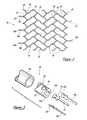
- FIG. 1is an oblique prospective view of an intravascular stent constructed in accordance with a preferred embodiment of the present invention
- FIG. 1 ais an expanded view of the proximal portion of the retaining legs shown in FIG. 1 ;
- FIG. 2is a side elevational view of the intravascular stent illustrated in FIG. 1 with the tubular stent being cut along a line and flattened into a single plane; and,
- FIG. 3illustrates in more detail the proximal retaining legs of FIG. 1 a and the interconnecting elements between the intravascular stent and a positioning catheter.
- FIG. 1illustrates a self-expanding stent device 10 which is laser cut to form a thin-walled, skeletal tubular member 11 comprised of nickel-titanium alloy. Once cut, the wall 12 of the tubular member 11 includes several openings, or cells 14 .
- a physicianis able to deliver embolic coils or other such devices through the cells 14 and into the aneurysm.
- the tubular member 11also functions to cover the mouth of the aneurysm thus obstructing, or partially obstructing, the flow of blood into the aneurysm. Also, the tubular member 11 prevents medical devices such as embolic coils from escaping the aneurysm.
- the preferred length of the skeletal tubular member 11may range from 0.0795 inches to 3.15 inches.
- the diameter of the tubular member 11varies depending on its deployment configuration. In a non-deployed or expanded state, the diameter of the tubular member 11 may extend up to about 0.4 inches. When the skeletal tubular member 11 is compressed to fit within the lumen of a deployment catheter, the diameter may be reduced to about 0.014 inches.
- proximal legs 18 , 18 a , and 18 bAttached to the proximal end 16 of the skeletal tubular member 11 are three proximal legs 18 , 18 a , and 18 b that extend longitudinally from the tubular member 11 .
- the proximal legs 18 , 18 a , and 18 bare preferably biased outwardly from the longitudinal axis of the tubular member 11 . This outwardly biased configuration aids in the deployment system as subsequently described.
- T-shaped or I-shaped attachment flanges 20 , 20 a , and 20 bare attached to the tips of each proximal leg 18 , 18 a , and 18 b .
- FIG. 1 adescribes the T-shaped or I-shaped flanges 20 , 20 a , and 20 b in more detail.
- Attached to the distal end 21 of the skeletal tubular member 11are two distal legs 22 and 22 a that extend longitudinally away from the tubular member 11 .
- FIG. 1 aillustrates in detail one of the T-shaped or I-shaped attachment flanges 20 which is also laser cut from the skeletal tubular member 11 at the proximal end of one of the proximal legs 18 .
- the T-shaped or I-shaped attachment flange 20is slightly arched and oriented on the proximal leg 18 such that the arch coincides with the wall 12 of the tubular member 11 .
- FIG. 2illustrates the repetitive cell pattern of the skeletal tubular member 11 .
- the cell patternmay be formed by interconnected non-inverted horizontal S-shaped members 24 and inverted horizontal S-shaped members 26 .
- Each S-shaped memberhas a proximal end 28 , a proximal intermediate section 30 , a proximal portion 31 , a distal intermediate section 32 , and a distal end 34 .
- the non-inverted horizontal S-shaped members 24are slightly flattened “S” configurations laying horizontal to the axis of the skeletal tubular member 11 and having its proximal portion 31 pointing up.
- the inverted horizontal S-shaped members 26are slightly flattened “S” configurations laying horizontal to the axis of the tubular member 11 and having its proximal portion 31 pointing down.
- the proximal end 28is the left tip of an S-shaped member.
- the proximal intermediate section 30 of a non-inverted horizontal S-shaped member 24is the negative (down) peak of an S-shaped member.
- the proximal intermediate section 30 of an inverted horizontal S-shaped member 26is the positive (up) peak of an S-shaped member.
- the proximal portion 31is the portion of an S-shaped member between the proximal end 28 and the proximal intermediate section 30 .
- the distal intermediate section 32 of a non-inverted horizontal S-shaped member 24is the positive peak of an S-shaped member.
- the distal intermediate section 32 of an inverted horizontal S-shaped member 26is the negative peak of an S-shaped member.
- the distal end 34is the right tip of an S-shaped member.
- the S-shaped membersare interconnected in a way to maximize “nesting” of the S-shaped members to thereby minimize the compressed diameter of the skeletal tubular member 11 during deployment.
- the proximal end 28 of each non-inverted horizontal S-shaped member 24is connected to the distal intermediate section 32 of an adjacent inverted horizontal S-shaped member 26 .
- the distal end 34 of each non-inverted horizontal S-shaped member 24is connected to the proximal intermediate section 30 of another adjacent inverted horizontal S-shaped member 26 .
- the proximal end 28 of each inverted horizontal S-shaped member 26is connected to the distal intermediate section 32 of an adjacent non-inverted horizontal S-shaped member 24 .
- each inverted horizontal S-shaped member 26is connected to the proximal intermediate section 30 of another adjacent non-inverted horizontal S-shaped member 24 .
- This interconnection of S-shaped memberspermits the cells 14 of the skeletal tubular member 11 to collapse and allows the tubular member 11 to attain a compressed diameter.
- the cell pattern of the skeletal tubular member 11may also be considered as being formed by interconnected sinusoidal members 36 .
- Each sinusoidal member 36has a period of approximately one and a half, or about 540 degrees.
- Each sinusoidal member 36has a proximal end 38 ,. a proximal peak 40 , a distal peak 42 , and a distal end 44 .
- the proximal end 38is the left tip of a sinusoidal member 36 .
- the proximal peak 40is the first peak to the right of the proximal end 38 and is either positive or negative.
- the distal peak 42is the second peak to the right of the proximal end 38 and is either positive or negative.
- each sinusoidal member 36has only one positive peak and one negative peak.
- the distal end 44is the right tip of a sinusoidal member 36 .
- the sinusoidal members 36are interconnected in a way to maximize “nesting” of the sinusoidal members to thereby minimize the compressed diameter of the skeletal tubular member 11 during deployment.
- the proximal end 38 of each sinusoidal member 36is connected to the distal peak 42 of an adjacent sinusoidal member 36 .
- the proximal peak 40 of each sinusoidal member 36is connected to the distal end 44 of another adjacent sinusoidal member 36 .
- the distal peak 42 of each sinusoidal member 36is connected to the proximal end 38 of yet another adjacent sinusoidal member 36 .
- the distal end 44 of each sinusoidal member 36is connected to the proximal peak 40 of still another adjacent sinusoidal member 36 .
- This interconnection of sinusoidal members 36permits the cells 14 of the skeletal tubular member 11 to collapse and allows the tubular member 11 to obtain a compressed diameter.
- proximal legs 18 , 18 a , and 18 bare connected to the proximal ends 28 of non-inverted horizontal S-shaped members 24 on the proximal end 16 of the skeletal tubular member 11 .
- the distal legs 22 and 22 aare connected to the distal ends 34 of inverted horizontal S-shaped members 26 on the distal end 21 of the tubular member 11 .
- the proximal legs 18 , 18 a , and 18 bare connected to the proximal ends 38 of sinusoidal members 36 on the proximal end 16 of the tubular member 11 .
- the distal legs 22 and 22 aare connected to the distal ends 44 of sinusoidal members 36 on the distal end 21 of the tubular member 11 .
- the stent device of the present inventionmay alternatively be coated with an agent, such as heparin or rapamycing, to prevent stenosis or restenosis of the vessel.
- an agentsuch as heparin or rapamycing
- examples of such coatingsare disclosed in U.S. Pat. Nos. 5,288,711; 5,516,781; 5,563,146 and 5,646,160. The disclosures in these patents are incorporated herein by reference.
- FIG. 3illustrates the deployment system 46 for the stent device 10 .
- the deployment system 46includes an outer sheath 48 which is essentially an elongated tubular member, similar to ordinary guiding catheters which are well known to those of ordinary skill in the art.
- the deployment system 46also includes an inner shaft 50 located coaxially within the outer sheath 48 prior to deployment.
- the inner shaft 50has a distal end 52 and a proximal end (not shown).
- the distal end 52 of the shaft 50has three grooves 54 , 54 a , and 54 b disposed thereon.
- the T-shaped or I-shaped attachment flanges 20 , 20 a , and 20 b on the proximal legs 18 , 18 a , and 18 b of the tubular member 11are set within the grooves 54 , 54 a , and 54 b of the inner shaft 50 , thereby releasably attaching the stent device 10 to the inner shaft 50 .
- This deployment systemis described in more detail in U.S. Pat. No. 6,267,783 assigned to the same assignee as the present patent application. The disclosure in this patent is incorporated herein by reference and made a part of the present patent application.
- a self-expanding stent devicecomprises a laser cut, skeletal tubular member having a plurality of cells.
Landscapes
- Health & Medical Sciences (AREA)
- Engineering & Computer Science (AREA)
- Biomedical Technology (AREA)
- Heart & Thoracic Surgery (AREA)
- Life Sciences & Earth Sciences (AREA)
- Cardiology (AREA)
- Oral & Maxillofacial Surgery (AREA)
- Transplantation (AREA)
- Physics & Mathematics (AREA)
- Vascular Medicine (AREA)
- Optics & Photonics (AREA)
- Animal Behavior & Ethology (AREA)
- General Health & Medical Sciences (AREA)
- Public Health (AREA)
- Veterinary Medicine (AREA)
- Prostheses (AREA)
- Media Introduction/Drainage Providing Device (AREA)
- Materials For Medical Uses (AREA)
Abstract
Description
This patent application is a divisional patent application of U.S. patent application Ser. No. 10/163,116, filed on Jun. 5, 2002, entitled, “Intravascular Stent Device,” now U.S. Pat. No. 6,673,106, which is a nonprovisional patent application of U.S. provisional patent application Ser. No. 60/298,326, filed on Jun. 14, 2001, entitled, “Intravascular Stent.”
1. Field of the Invention
This invention relates to intravascular devices for implantation within a vessel of the body, and more particularly to a stent device which may be used in the treatment of blood vessel disorders. More specifically, the intravascular device may take the form of an aneurysm cover to be used in the treatment of aneurysms which occur in the brain.
2. Description of the Prior Art
On a worldwide basis, nearly one million balloon angioplasties were performed in 1997 to treat vascular disease, including blood vessels clogged or narrowed by a lesion or stenosis. The objective of this procedure is to increase the inner diameter or cross-sectional area of the vessel passage, or lumen, through which blood flows.
Another serious vascular defect is an area of weakened vessel wall that causes a bulge, or bubble, to protrude out in a radial direction from the vessel. This type of defect is called an aneurysm. If untreated, the aneurysm may continue expanding until it bursts thereby causing hemorrhaging from the vessel.
In an effort to prevent restenosis or treat an aneurysm without requiring surgery, short flexible cylinders or scaffolds, made of metal or polymers, are often placed into a vessel to maintain or improve blood flow. Referred to as stents, various types of these devices are widely used for reinforcing diseased blood vessels, for opening occluded blood vessels, and for defining an internal lumen to relieve pressure in an aneurysm. The stents allow blood to flow through the vessels at an improved rate while providing the desired lumen opening or structural integrity lost by the damaged vessels. Some stents are expanded to the proper size by inflating a balloon catheter, referred to as “balloon expandable” stents, while others are designed to elastically resist compression in a “self-expanding” manner.
Balloon expandable stents and self-expanding stents are generally delivered in a cylindrical form, crimped to a smaller diameter and are placed within a vessel using a catheter-based delivery system. When positioned at a desired site within a vessel, these devices are expanded by a balloon, or allowed to “self-expand,” to the desired diameter.
One such stent for treatment of abdominal aortic aneurysms is disclosed in U.S. Pat. No. 6,267,783 to Robert P. Letendre, et al. This patent discloses a self-expanding stent which may be used in the treatment of aortic aneurysms. This device may be easily recaptured after placement and repositioned to a new position within the vessel. This patent, assigned to a related company, is subsequently referred to and the disclosure therein is incorporated and made a part of the subject patent application.
Another stent aneurysm treatment device is disclosed in U.S. Pat. No. 6,361,558, assigned to the same assignee as the present application. This patent discloses vasculature stents of various configurations which may be used as aneurysm covers for occluding, or partially occluding, aneurysms located at various positions along the blood vessels.
There is a need for an improved stent which may be easily delivered to a vasculature site through a very small catheter, is capable of being repositioned and which exhibits sufficient structural integrity and resilience under radial compressive forces. More particularly, there is a need for such a stent that, in its compressed state prior to delivery of the stent, has a diameter which is extremely small. Such a stent could be placed in a very small microcatheter for subsequent positioning within a vessel of the human brain. Obviously, such vessels are extremely small and very tortuous throughout their length.
In accordance with one aspect of the present invention, there is provided a self-expanding stent which includes a small diameter skeletal tubular member. The skeletal tubular member is comprised of a plurality of cells which are formed by a plurality of interconnected, non-inverted horizontal and inverted horizontal S-shaped members. The S-shaped members are generally parallel to the longitudinal axis of the tubular member and are interconnected in a repeating pattern. Each of the S-shaped members has a proximal end, a distal end, a proximal intermediate section and a distal intermediate section. The proximal end of each non-inverted horizontal S-shaped member is attached to the distal intermediate section of an adjacent inverted horizontal S-shaped member, the distal end of each non-inverted horizontal S-shaped member is attached to the proximal intermediate section of another adjacent inverted horizontal S-shaped member, the proximal end of each inverted horizontal S-shaped member is attached to the distal intermediate section of an adjacent non-inverted horizontal S-shaped member, and the distal end of each inverted horizontal S-shaped member is attached to said proximal intermediate section of another adjacent non-inverted horizontal S-shaped member. With this configuration, the skeletal tubular member may be compressed to a very small diameter because of “nesting” of adjacent S-shaped members.
In accordance with another aspect of the present invention, as the skeletal tubular member is compressed into a small diameter, each proximal intermediate section of each non-inverted horizontal S-shaped member pulls on a distal end of an adjacent inverted horizontal S-shaped member, each distal intermediate section of each non-inverted horizontal S-shaped member pulls on a proximal end of another adjacent inverted horizontal S-shaped member, each proximal intermediate section of each inverted horizontal S-shaped member pulls on the distal end of an adjacent non-inverted horizontal S-shaped member, and each distal intermediate section of each inverted S-shaped member pulls on the proximal end of an adjacent non-inverted horizontal S-shaped member thereby causing the “cells” of the S-shaped member, “nest” and cause the tubular member to attain the small diameter.
In accordance with another aspect of the present invention, the skeletal tubular member includes at least two proximal legs which are attached to the skeletal tubular member and which extend generally parallel to the longitudinal axis of the tubular member. At least one of the proximal legs includes a T-shaped flange adjacent to the end of the proximal leg for attachment to a stent release mechanism.
In accordance with another aspect of the present invention, the legs are biased outwardly away from the longitudinal axis of the skeletal tubular member. The legs may also include radiopaque markers for providing an indication of the location of the stent device as the device is positioned within a vessel.
In accordance with still another aspect of the present invention, the skeletal tubular member may include distal legs which are attached to and extend generally parallel to the longitudinal axis of the skeletal tubular member. These legs may also include radiopaque markers for providing positioning information.
In accordance with still another aspect of the present invention there is provided a self-expanding stent device which includes a small diameter skeletal tubular member. The wall of the skeletal tubular member is comprised of a plurality of cells which are formed by interconnected sinusoidal members. The sinusoidal members are generally parallel to the longitudinal axis of the tubular member. Each sinusoidal member extends for one and a half sinusoidal periods, or about 540 degrees. Each sinusoidal member has a proximal end, a distal end, a proximal peak and a distal peak. The sinusoidal members have a repeating pattern in which the proximal end of each sinusoidal member is attached to the distal peak of an adjacent sinusoidal member. Also, the distal end of each sinusoidal member is attached to the proximal peak of another adjacent sinusoidal member.
In accordance with another aspect of the present invention, in its compressed state, the proximal peak of each sinusoidal member pulls the distal end of an adjacent sinusoidal member and the distal peak of each sinusoidal member pulls the proximal end of an adjacent sinusoidal member causing the cells of the wall to collapse, or “nest,” thereby allowing the skeletal tubular member to attain a small compressed diameter.
In accordance with still another aspect of the present invention, a self-expanding aneurysm cover is provided which when placed across an aneurysm of a blood vessel reduces, or obstructs, the flow of blood between the aneurysm and its related blood vessel. The aneurysm cover includes a small diameter skeletal tubular member which is comprised of a plurality of cells which are formed by a plurality of interconnected, non-inverted horizontal and inverted horizontal S-shaped members. The S-shaped members are generally parallel to the longitudinal axis of the tubular member and are interconnected in a repeating pattern. Each of the S-shaped members has a proximal end, a distal end, a proximal intermediate section and a distal intermediate section. The proximal end of each non-inverted horizontal S-shaped member is attached to the distal intermediate section of an adjacent inverted horizontal S-shaped member, the distal end of each non-inverted horizontal S-shaped member is attached to the proximal intermediate section of another adjacent inverted horizontal S-shaped member, the proximal end of each inverted horizontal S-shaped member is attached to the distal intermediate section of an adjacent non-inverted horizontal S-shaped member, and the distal end of each inverted horizontal S-shaped member is attached to said proximal intermediate section of another adjacent non-inverted horizontal S-shaped member. With this configuration, the skeletal tubular member may be compressed to a very small diameter because of “nesting” of adjacent S-shaped members.
These and other aspects of the invention and the advantages thereof will be clearly understood from the following description and drawings of a preferred embodiment of the present invention.
The preferred length of theskeletal tubular member 11 may range from 0.0795 inches to 3.15 inches. The diameter of thetubular member 11 varies depending on its deployment configuration. In a non-deployed or expanded state, the diameter of thetubular member 11 may extend up to about 0.4 inches. When theskeletal tubular member 11 is compressed to fit within the lumen of a deployment catheter, the diameter may be reduced to about 0.014 inches.
Attached to the proximal end16 of theskeletal tubular member 11 are threeproximal legs tubular member 11. Theproximal legs tubular member 11. This outwardly biased configuration aids in the deployment system as subsequently described.
T-shaped or I-shapedattachment flanges proximal leg FIG. 1 adescribes the T-shaped or I-shapedflanges skeletal tubular member 11 are twodistal legs tubular member 11.
The S-shaped members are interconnected in a way to maximize “nesting” of the S-shaped members to thereby minimize the compressed diameter of theskeletal tubular member 11 during deployment. Theproximal end 28 of each non-inverted horizontal S-shapedmember 24 is connected to the distalintermediate section 32 of an adjacent inverted horizontal S-shapedmember 26. Thedistal end 34 of each non-inverted horizontal S-shapedmember 24 is connected to the proximalintermediate section 30 of another adjacent inverted horizontal S-shapedmember 26. Theproximal end 28 of each inverted horizontal S-shapedmember 26 is connected to the distalintermediate section 32 of an adjacent non-inverted horizontal S-shapedmember 24. Thedistal end 34 of each inverted horizontal S-shapedmember 26 is connected to the proximalintermediate section 30 of another adjacent non-inverted horizontal S-shapedmember 24. This interconnection of S-shaped members permits thecells 14 of theskeletal tubular member 11 to collapse and allows thetubular member 11 to attain a compressed diameter.
The cell pattern of theskeletal tubular member 11 may also be considered as being formed by interconnectedsinusoidal members 36. Eachsinusoidal member 36 has a period of approximately one and a half, or about 540 degrees. Eachsinusoidal member 36 has aproximal end 38,. aproximal peak 40, adistal peak 42, and adistal end 44. Theproximal end 38 is the left tip of asinusoidal member 36. Theproximal peak 40 is the first peak to the right of theproximal end 38 and is either positive or negative. Thedistal peak 42 is the second peak to the right of theproximal end 38 and is either positive or negative. However, eachsinusoidal member 36 has only one positive peak and one negative peak. Thedistal end 44 is the right tip of asinusoidal member 36.
Thesinusoidal members 36 are interconnected in a way to maximize “nesting” of the sinusoidal members to thereby minimize the compressed diameter of theskeletal tubular member 11 during deployment. Theproximal end 38 of eachsinusoidal member 36 is connected to thedistal peak 42 of an adjacentsinusoidal member 36. Theproximal peak 40 of eachsinusoidal member 36 is connected to thedistal end 44 of another adjacentsinusoidal member 36. Thedistal peak 42 of eachsinusoidal member 36 is connected to theproximal end 38 of yet another adjacentsinusoidal member 36. Thedistal end 44 of eachsinusoidal member 36 is connected to theproximal peak 40 of still another adjacentsinusoidal member 36. This interconnection ofsinusoidal members 36 permits thecells 14 of theskeletal tubular member 11 to collapse and allows thetubular member 11 to obtain a compressed diameter.
Also illustrated inFIG. 2 are theproximal legs distal legs proximal legs members 24 on the proximal end16 of theskeletal tubular member 11. Thedistal legs members 26 on the distal end21 of thetubular member 11. In the repetitive cell pattern formed bysinusoidal members 36, theproximal legs sinusoidal members 36 on the proximal end16 of thetubular member 11. Thedistal legs sinusoidal members 36 on the distal end21 of thetubular member 11.
It should be understood that the stent device of the present invention may alternatively be coated with an agent, such as heparin or rapamycing, to prevent stenosis or restenosis of the vessel. Examples of such coatings are disclosed in U.S. Pat. Nos. 5,288,711; 5,516,781; 5,563,146 and 5,646,160. The disclosures in these patents are incorporated herein by reference.
A novel system has been disclosed in which a self-expanding stent device comprises a laser cut, skeletal tubular member having a plurality of cells. Although a preferred embodiment of the invention has been described, it is to be understood that various modifications may be made by those skilled in the art without departing from the scope of the claims which follow.
Claims (8)
1. A self-expanding stent device comprising:
a small diameter skeletal tubular member having a thin wall and having a proximal end and a distal end; said wall of said tubular member comprised of a plurality of cells which are formed by a plurality of interconnected, non-inverted horizontal and inverted horizontal S-shaped members; said interconnected S-shaped members are generally parallel with the longitudinal axis of said tubular member; each interconnected S-shaped member has a proximal end, a distal end, a proximal intermediate section, and a distal intermediate section; and,
said interconnected S-shaped members having a repeating pattern comprised of a configuration in which said proximal end of each non-inverted horizontal S-shaped member is attached to said distal intermediate section of an adjacent inverted horizontal S-shaped member, and said proximal end of each inverted horizontal S-shaped member is attached to said distal intermediate section of an adjacent non-inverted horizontal S-shaped member.
2. A self-expanding stent device as defined inclaim 1 , in which said tubular member has a small compressed diameter for delivery within a vessel and a normally biased expanded diameter for retaining said stent device against the walls of the vessel; upon compression of said tubular member to its small diameter said distal intermediate section of each non-inverted horizontal S-shaped member pulls said proximal end of another adjacent inverted horizontal S-shaped member, and said distal intermediate section of each inverted horizontal S-shaped member pulls said proximal end of another adjacent non-inverted horizontal S-shaped member thereby causing said cells of said wall to collapse and cause said tubular member to attain said small diameter.
3. A self-expanding stent device as defined inclaim 1 , wherein said tubular member includes a proximal leg; said proximal leg extends generally parallel to the longitudinal axis of said tubular member and is attached to the proximal end of said tubular member; the proximal leg includes an attachment flange.
4. A self-expanding stent device as defined inclaim 3 , wherein said proximal leg is biased outwardly from the longitudinal axis of said tubular member.
5. A self-expanding stent device as defined inclaim 2 , wherein said stent device is constructed from a nickel-titanium alloy.
6. A self-expanding stent device as defined inclaim 3 , wherein said proximal leg includes a radiopaque marker.
7. A self-expanding stent device as defined inclaim 1 , wherein said tubular member includes at least one distal leg; said distal leg extends generally parallel to the longitudinal axis of said tubular member and is attached to the distal end of said tubular member.
8. A self-expanding stent device as defined inclaim 7 , wherein said distal leg includes a radiopaque marker.
Priority Applications (2)
| Application Number | Priority Date | Filing Date | Title |
|---|---|---|---|
| US10/722,336US6960228B2 (en) | 2001-06-14 | 2003-11-25 | Intravascular stent device |
| US11/166,306US20050234536A1 (en) | 2001-06-14 | 2005-06-24 | Intravascular stent device |
Applications Claiming Priority (3)
| Application Number | Priority Date | Filing Date | Title |
|---|---|---|---|
| US29832601P | 2001-06-14 | 2001-06-14 | |
| US10/163,116US6673106B2 (en) | 2001-06-14 | 2002-06-05 | Intravascular stent device |
| US10/722,336US6960228B2 (en) | 2001-06-14 | 2003-11-25 | Intravascular stent device |
Related Parent Applications (1)
| Application Number | Title | Priority Date | Filing Date |
|---|---|---|---|
| US10/163,116DivisionUS6673106B2 (en) | 2001-06-14 | 2002-06-05 | Intravascular stent device |
Related Child Applications (1)
| Application Number | Title | Priority Date | Filing Date |
|---|---|---|---|
| US11/166,306DivisionUS20050234536A1 (en) | 2001-06-14 | 2005-06-24 | Intravascular stent device |
Publications (2)
| Publication Number | Publication Date |
|---|---|
| US20040158306A1 US20040158306A1 (en) | 2004-08-12 |
| US6960228B2true US6960228B2 (en) | 2005-11-01 |
Family
ID=26859370
Family Applications (3)
| Application Number | Title | Priority Date | Filing Date |
|---|---|---|---|
| US10/163,116Expired - LifetimeUS6673106B2 (en) | 2001-06-14 | 2002-06-05 | Intravascular stent device |
| US10/722,336Expired - LifetimeUS6960228B2 (en) | 2001-06-14 | 2003-11-25 | Intravascular stent device |
| US11/166,306AbandonedUS20050234536A1 (en) | 2001-06-14 | 2005-06-24 | Intravascular stent device |
Family Applications Before (1)
| Application Number | Title | Priority Date | Filing Date |
|---|---|---|---|
| US10/163,116Expired - LifetimeUS6673106B2 (en) | 2001-06-14 | 2002-06-05 | Intravascular stent device |
Family Applications After (1)
| Application Number | Title | Priority Date | Filing Date |
|---|---|---|---|
| US11/166,306AbandonedUS20050234536A1 (en) | 2001-06-14 | 2005-06-24 | Intravascular stent device |
Country Status (5)
| Country | Link |
|---|---|
| US (3) | US6673106B2 (en) |
| EP (1) | EP1266639B1 (en) |
| JP (1) | JP4610842B2 (en) |
| AT (1) | ATE334641T1 (en) |
| DE (1) | DE60213516T2 (en) |
Cited By (37)
| Publication number | Priority date | Publication date | Assignee | Title |
|---|---|---|---|---|
| US20060224230A1 (en)* | 2000-10-16 | 2006-10-05 | Rivelli Patrick Jr | Neurovascular stent and method |
| US20070173925A1 (en)* | 2006-01-25 | 2007-07-26 | Cornova, Inc. | Flexible expandable stent |
| USD553746S1 (en)* | 2006-01-25 | 2007-10-23 | Cornova, Inc. | Opened stent device |
| US20080177371A1 (en)* | 2006-08-28 | 2008-07-24 | Cornova, Inc. | Implantable devices and methods of forming the same |
| US20110009950A1 (en)* | 2009-07-08 | 2011-01-13 | Concentric Medical, Inc. | Vascular and bodily duct treatment devices and methods |
| US20110009940A1 (en)* | 2009-07-08 | 2011-01-13 | Concentric Medical, Inc. | Vascular and bodily duct treatment devices and methods |
| US20110009875A1 (en)* | 2009-07-08 | 2011-01-13 | Concentric Medical, Inc. | Embolic obstruction retrieval devices and methods |
| US20110009941A1 (en)* | 2009-07-08 | 2011-01-13 | Concentric Medical, Inc. | Vascular and bodily duct treatment devices and methods |
| US20110184456A1 (en)* | 2009-07-08 | 2011-07-28 | Concentric Medical, Inc. | Vascular and bodily duct treatment devices and methods |
| US8298244B2 (en) | 2006-10-26 | 2012-10-30 | Tyco Healtcare Group Lp | Intracorporeal grasping device |
| US8529596B2 (en) | 2009-07-08 | 2013-09-10 | Concentric Medical, Inc. | Vascular and bodily duct treatment devices and methods |
| US8632584B2 (en) | 2002-07-19 | 2014-01-21 | Dendron Gmbh | Medical implant having a curlable matrix structure and method of use |
| US8679142B2 (en) | 2008-02-22 | 2014-03-25 | Covidien Lp | Methods and apparatus for flow restoration |
| EP2777650A1 (en) | 2013-03-13 | 2014-09-17 | DePuy Synthes Products, LLC | Distal capture device for a self-expanding stent |
| US8999364B2 (en) | 2004-06-15 | 2015-04-07 | Nanyang Technological University | Implantable article, method of forming same and method for reducing thrombogenicity |
| US9039749B2 (en) | 2010-10-01 | 2015-05-26 | Covidien Lp | Methods and apparatuses for flow restoration and implanting members in the human body |
| US9072537B2 (en) | 2009-07-08 | 2015-07-07 | Concentric Medical, Inc. | Vascular and bodily duct treatment devices and methods |
| US9149278B2 (en) | 2013-03-13 | 2015-10-06 | DePuy Synthes Products, Inc. | Occlusive device delivery system with mechanical detachment |
| US9908143B2 (en) | 2008-06-20 | 2018-03-06 | Amaranth Medical Pte. | Stent fabrication via tubular casting processes |
| US10076399B2 (en) | 2013-09-13 | 2018-09-18 | Covidien Lp | Endovascular device engagement |
| US10172734B2 (en) | 2013-03-13 | 2019-01-08 | DePuy Synthes Products, Inc. | Capture tube mechanism for delivering and releasing a stent |
| US10292851B2 (en) | 2016-09-30 | 2019-05-21 | DePuy Synthes Products, Inc. | Self-expanding device delivery apparatus with dual function bump |
| US10413310B2 (en) | 2007-10-17 | 2019-09-17 | Covidien Lp | Restoring blood flow and clot removal during acute ischemic stroke |
| US10561509B2 (en) | 2013-03-13 | 2020-02-18 | DePuy Synthes Products, Inc. | Braided stent with expansion ring and method of delivery |
| US10603157B2 (en) | 2013-03-13 | 2020-03-31 | DePuy Synthes Products, Inc. | Braid implant delivery and retraction device with distal engagement |
| US10646359B2 (en) | 2008-06-20 | 2020-05-12 | Amaranth Medical Pte. | Stent fabrication via tubular casting processes |
| US10722255B2 (en) | 2008-12-23 | 2020-07-28 | Covidien Lp | Systems and methods for removing obstructive matter from body lumens and treating vascular defects |
| US10821008B2 (en) | 2016-08-25 | 2020-11-03 | DePuy Synthes Products, Inc. | Expansion ring for a braided stent |
| US10821010B2 (en) | 2014-08-27 | 2020-11-03 | DePuy Synthes Products, Inc. | Method of making a multi-strand implant with enhanced radiopacity |
| US10893963B2 (en) | 2018-08-06 | 2021-01-19 | DePuy Synthes Products, Inc. | Stent delivery with expansion assisting delivery wire |
| US11013833B2 (en) | 2015-08-03 | 2021-05-25 | Advanced Endovascular Therapeutics | Coatings for medical devices |
| US11039944B2 (en) | 2018-12-27 | 2021-06-22 | DePuy Synthes Products, Inc. | Braided stent system with one or more expansion rings |
| US11090175B2 (en) | 2018-07-30 | 2021-08-17 | DePuy Synthes Products, Inc. | Systems and methods of manufacturing and using an expansion ring |
| EP3967280A1 (en) | 2020-05-15 | 2022-03-16 | DePuy Synthes Products, Inc. | Systems and methods for treatment of defects in the vasculature |
| US11337714B2 (en) | 2007-10-17 | 2022-05-24 | Covidien Lp | Restoring blood flow and clot removal during acute ischemic stroke |
| US11357648B2 (en) | 2018-08-06 | 2022-06-14 | DePuy Synthes Products, Inc. | Systems and methods of using a braided implant |
| US11931484B2 (en) | 2008-06-20 | 2024-03-19 | Razmodics Llc | Composite stent having multi-axial flexibility and method of manufacture thereof |
Families Citing this family (128)
| Publication number | Priority date | Publication date | Assignee | Title |
|---|---|---|---|---|
| US20060178727A1 (en)* | 1998-12-03 | 2006-08-10 | Jacob Richter | Hybrid amorphous metal alloy stent |
| US20060122691A1 (en)* | 1998-12-03 | 2006-06-08 | Jacob Richter | Hybrid stent |
| US20050033399A1 (en)* | 1998-12-03 | 2005-02-10 | Jacob Richter | Hybrid stent |
| US8382821B2 (en)* | 1998-12-03 | 2013-02-26 | Medinol Ltd. | Helical hybrid stent |
| US20070219642A1 (en)* | 1998-12-03 | 2007-09-20 | Jacob Richter | Hybrid stent having a fiber or wire backbone |
| US6602283B2 (en) | 2001-04-06 | 2003-08-05 | Scimed Life Systems, Inc. | Stent design |
| DE10118944B4 (en) | 2001-04-18 | 2013-01-31 | Merit Medical Systems, Inc. | Removable, essentially cylindrical implants |
| US6673106B2 (en)* | 2001-06-14 | 2004-01-06 | Cordis Neurovascular, Inc. | Intravascular stent device |
| AU2002320456A1 (en) | 2001-07-26 | 2003-02-17 | Alveolus Inc. | Removable stent and method of using the same |
| JP4331610B2 (en) | 2001-12-20 | 2009-09-16 | トリバスキュラー2,インコーポレイティド | Advanced endovascular graft |
| US7147661B2 (en) | 2001-12-20 | 2006-12-12 | Boston Scientific Santa Rosa Corp. | Radially expandable stent |
| US7060089B2 (en) | 2002-01-23 | 2006-06-13 | Boston Scientific Scimed, Inc. | Multi-layer stent |
| US7195648B2 (en)* | 2002-05-16 | 2007-03-27 | Cordis Neurovascular, Inc. | Intravascular stent device |
| US7001422B2 (en)* | 2002-09-23 | 2006-02-21 | Cordis Neurovascular, Inc | Expandable stent and delivery system |
| US7637942B2 (en)* | 2002-11-05 | 2009-12-29 | Merit Medical Systems, Inc. | Coated stent with geometry determinated functionality and method of making the same |
| US7527644B2 (en) | 2002-11-05 | 2009-05-05 | Alveolus Inc. | Stent with geometry determinated functionality and method of making the same |
| US7959671B2 (en) | 2002-11-05 | 2011-06-14 | Merit Medical Systems, Inc. | Differential covering and coating methods |
| US7875068B2 (en) | 2002-11-05 | 2011-01-25 | Merit Medical Systems, Inc. | Removable biliary stent |
| CA2519226C (en)* | 2003-03-19 | 2013-01-15 | Advanced Bio Prosthetic Surfaces, Ltd. | Endoluminal stent having mid-strut interconnecting members |
| US20040267348A1 (en)* | 2003-04-11 | 2004-12-30 | Gunderson Richard C. | Medical device delivery systems |
| US8083791B2 (en) | 2003-04-14 | 2011-12-27 | Tryton Medical, Inc. | Method of treating a lumenal bifurcation |
| US7717953B2 (en)* | 2004-10-13 | 2010-05-18 | Tryton Medical, Inc. | Delivery system for placement of prosthesis at luminal OS |
| US8109987B2 (en)* | 2003-04-14 | 2012-02-07 | Tryton Medical, Inc. | Method of treating a lumenal bifurcation |
| US7731747B2 (en)* | 2003-04-14 | 2010-06-08 | Tryton Medical, Inc. | Vascular bifurcation prosthesis with multiple thin fronds |
| US7972372B2 (en)* | 2003-04-14 | 2011-07-05 | Tryton Medical, Inc. | Kit for treating vascular bifurcations |
| US7758630B2 (en)* | 2003-04-14 | 2010-07-20 | Tryton Medical, Inc. | Helical ostium support for treating vascular bifurcations |
| US7481834B2 (en)* | 2003-04-14 | 2009-01-27 | Tryton Medical, Inc. | Stent for placement at luminal os |
| US9155639B2 (en)* | 2009-04-22 | 2015-10-13 | Medinol Ltd. | Helical hybrid stent |
| US9039755B2 (en) | 2003-06-27 | 2015-05-26 | Medinol Ltd. | Helical hybrid stent |
| US20050049668A1 (en)* | 2003-08-29 | 2005-03-03 | Jones Donald K. | Self-expanding stent and stent delivery system for treatment of vascular stenosis |
| US20050049669A1 (en)* | 2003-08-29 | 2005-03-03 | Jones Donald K. | Self-expanding stent and stent delivery system with distal protection |
| US20050049670A1 (en)* | 2003-08-29 | 2005-03-03 | Jones Donald K. | Self-expanding stent and stent delivery system for treatment of vascular disease |
| US20050096725A1 (en) | 2003-10-29 | 2005-05-05 | Pomeranz Mark L. | Expandable stent having removable slat members |
| US7763064B2 (en)* | 2004-06-08 | 2010-07-27 | Medinol, Ltd. | Stent having struts with reverse direction curvature |
| EP1773871B1 (en) | 2004-06-17 | 2014-10-15 | Thrasos Innovation, Inc. | Tdf-related compounds and analogs thereof |
| US7744641B2 (en)* | 2004-07-21 | 2010-06-29 | Boston Scientific Scimed, Inc. | Expandable framework with overlapping connectors |
| US7303580B2 (en)* | 2004-07-26 | 2007-12-04 | Cook Incorporated | Stent delivery system allowing controlled release of a stent |
| US20070292478A1 (en) | 2004-08-30 | 2007-12-20 | Popowski Youri | Medical Implant Provided with Inhibitors of Atp Synthesis |
| US20080004653A1 (en) | 2004-09-17 | 2008-01-03 | Sherman Darren R | Thin Film Devices for Occlusion of a Vessel |
| US20060064064A1 (en)* | 2004-09-17 | 2006-03-23 | Jang G D | Two-step/dual-diameter balloon angioplasty catheter for bifurcation and side-branch vascular anatomy |
| EP2468348B1 (en) | 2004-09-17 | 2016-10-26 | Codman & Shurtleff, Inc. | Thin film metallic devices for plugging aneurysms or vessels |
| US7887579B2 (en)* | 2004-09-29 | 2011-02-15 | Merit Medical Systems, Inc. | Active stent |
| US7156871B2 (en)* | 2004-10-28 | 2007-01-02 | Cordis Neurovascular, Inc. | Expandable stent having a stabilized portion |
| US7147659B2 (en)* | 2004-10-28 | 2006-12-12 | Cordis Neurovascular, Inc. | Expandable stent having a dissolvable portion |
| WO2006063222A1 (en)* | 2004-12-09 | 2006-06-15 | Med Institute, Inc. | Variable curvature stent |
| DE102005003632A1 (en) | 2005-01-20 | 2006-08-17 | Fraunhofer-Gesellschaft zur Förderung der angewandten Forschung e.V. | Catheter for the transvascular implantation of heart valve prostheses |
| US20080188803A1 (en)* | 2005-02-03 | 2008-08-07 | Jang G David | Triple-profile balloon catheter |
| AR054656A1 (en)* | 2005-04-03 | 2007-07-11 | Liliana Rosa Grinfeld | STENT FOR OSTIAL INJURIES AND VASCULAR FORKS |
| JP5523700B2 (en) | 2005-04-04 | 2014-06-18 | フレキシブル ステンティング ソリューションズ,インク. | Flexible stent |
| US7731654B2 (en)* | 2005-05-13 | 2010-06-08 | Merit Medical Systems, Inc. | Delivery device with viewing window and associated method |
| EP2927241A1 (en) | 2005-09-20 | 2015-10-07 | Thrasos Innovation, Inc. | TDF-related compounds and analogs thereof |
| US20070250148A1 (en)* | 2005-09-26 | 2007-10-25 | Perry Kenneth E Jr | Systems, apparatus and methods related to helical, non-helical or removable stents with rectilinear ends |
| US8956400B2 (en)* | 2005-10-14 | 2015-02-17 | Flexible Stenting Solutions, Inc. | Helical stent |
| US20070156230A1 (en) | 2006-01-04 | 2007-07-05 | Dugan Stephen R | Stents with radiopaque markers |
| US7655031B2 (en)* | 2006-04-28 | 2010-02-02 | Codman & Shurtleff, Inc. | Stent delivery system with improved retraction member |
| US8690935B2 (en)* | 2006-04-28 | 2014-04-08 | DePuy Synthes Products, LLC | Stent delivery system with threaded engagement and method |
| US8690938B2 (en)* | 2006-05-26 | 2014-04-08 | DePuy Synthes Products, LLC | Occlusion device combination of stent and mesh with diamond-shaped porosity |
| US20130325107A1 (en) | 2006-05-26 | 2013-12-05 | Abbott Cardiovascular Systems Inc. | Stents With Radiopaque Markers |
| US8118859B2 (en)* | 2006-05-26 | 2012-02-21 | Codman & Shurtleff, Inc. | Occlusion device combination of stent and mesh having offset parallelogram porosity |
| US20080015684A1 (en) | 2006-07-11 | 2008-01-17 | Wu Patrick P | Method And Apparatus For Attaching Radiopaque Markers To A Stent |
| US8876894B2 (en) | 2006-09-19 | 2014-11-04 | Medtronic Ventor Technologies Ltd. | Leaflet-sensitive valve fixation member |
| US11304800B2 (en) | 2006-09-19 | 2022-04-19 | Medtronic Ventor Technologies Ltd. | Sinus-engaging valve fixation member |
| US8834564B2 (en)* | 2006-09-19 | 2014-09-16 | Medtronic, Inc. | Sinus-engaging valve fixation member |
| US8974514B2 (en) | 2007-03-13 | 2015-03-10 | Abbott Cardiovascular Systems Inc. | Intravascular stent with integrated link and ring strut |
| US8062347B2 (en) | 2007-03-23 | 2011-11-22 | Codman & Shurtleff, Inc. | Implantable stents having a plurality of varying parallelogrammic cells and methods for manufacturing the same |
| US8545548B2 (en) | 2007-03-30 | 2013-10-01 | DePuy Synthes Products, LLC | Radiopaque markers for implantable stents and methods for manufacturing the same |
| US20080243226A1 (en)* | 2007-03-30 | 2008-10-02 | Fernandez Jose E | Implantable stents with radiopaque markers and methods for manufacturing the same |
| US9138315B2 (en)* | 2007-04-13 | 2015-09-22 | Jenavalve Technology Gmbh | Medical device for treating a heart valve insufficiency or stenosis |
| US7896915B2 (en) | 2007-04-13 | 2011-03-01 | Jenavalve Technology, Inc. | Medical device for treating a heart valve insufficiency |
| US7988723B2 (en) | 2007-08-02 | 2011-08-02 | Flexible Stenting Solutions, Inc. | Flexible stent |
| US20090082841A1 (en)* | 2007-09-26 | 2009-03-26 | Boston Scientific Corporation | Apparatus for securing stent barbs |
| US8226701B2 (en) | 2007-09-26 | 2012-07-24 | Trivascular, Inc. | Stent and delivery system for deployment thereof |
| US8066755B2 (en)* | 2007-09-26 | 2011-11-29 | Trivascular, Inc. | System and method of pivoted stent deployment |
| US8663309B2 (en)* | 2007-09-26 | 2014-03-04 | Trivascular, Inc. | Asymmetric stent apparatus and method |
| US10159557B2 (en) | 2007-10-04 | 2018-12-25 | Trivascular, Inc. | Modular vascular graft for low profile percutaneous delivery |
| US8083789B2 (en)* | 2007-11-16 | 2011-12-27 | Trivascular, Inc. | Securement assembly and method for expandable endovascular device |
| US8328861B2 (en) | 2007-11-16 | 2012-12-11 | Trivascular, Inc. | Delivery system and method for bifurcated graft |
| US20100331958A1 (en)* | 2007-12-20 | 2010-12-30 | Trivascular, Inc. | Hinged endovascular device |
| US8291781B2 (en) | 2007-12-21 | 2012-10-23 | Schlumberger Technology Corporation | System and methods for actuating reversibly expandable structures |
| CA2714062A1 (en) | 2008-01-24 | 2009-07-30 | Medtronic, Inc. | Stents for prosthetic heart valves |
| US8157853B2 (en) | 2008-01-24 | 2012-04-17 | Medtronic, Inc. | Delivery systems and methods of implantation for prosthetic heart valves |
| BR112012021347A2 (en) | 2008-02-26 | 2019-09-24 | Jenavalve Tecnology Inc | stent for positioning and anchoring a valve prosthesis at an implantation site in a patient's heart |
| US9044318B2 (en) | 2008-02-26 | 2015-06-02 | Jenavalve Technology Gmbh | Stent for the positioning and anchoring of a valvular prosthesis |
| US8876876B2 (en)* | 2008-06-06 | 2014-11-04 | Back Bay Medical Inc. | Prosthesis and delivery system |
| US9387312B2 (en) | 2008-09-15 | 2016-07-12 | Brightwater Medical, Inc. | Convertible nephroureteral catheter |
| US9149376B2 (en) | 2008-10-06 | 2015-10-06 | Cordis Corporation | Reconstrainable stent delivery system |
| DE102009003890A1 (en) | 2009-01-02 | 2010-07-08 | Bioregeneration Gmbh | Apparatus comprising a device and a liner implantable in a vessel of the body of a patient, and methods of making same |
| EP2394610A1 (en)* | 2009-02-06 | 2011-12-14 | Keio University | Stent to be used in tubular organ in vivo |
| US8382818B2 (en)* | 2009-07-02 | 2013-02-26 | Tryton Medical, Inc. | Ostium support for treating vascular bifurcations |
| US9956100B2 (en) | 2009-09-15 | 2018-05-01 | Brightwater Medical, Inc. | Systems and methods for coupling and decoupling a catheter |
| US8808353B2 (en) | 2010-01-30 | 2014-08-19 | Abbott Cardiovascular Systems Inc. | Crush recoverable polymer scaffolds having a low crossing profile |
| US8568471B2 (en) | 2010-01-30 | 2013-10-29 | Abbott Cardiovascular Systems Inc. | Crush recoverable polymer scaffolds |
| US20110218609A1 (en)* | 2010-02-10 | 2011-09-08 | Trivascular, Inc. | Fill tube manifold and delivery methods for endovascular graft |
| US10856978B2 (en) | 2010-05-20 | 2020-12-08 | Jenavalve Technology, Inc. | Catheter system |
| WO2011147849A1 (en) | 2010-05-25 | 2011-12-01 | Jenavalve Technology Inc. | Prosthetic heart valve and transcatheter delivered endoprosthesis comprising a prosthetic heart valve and a stent |
| US9192495B2 (en) | 2010-07-23 | 2015-11-24 | Medtronic, Inc. | Attachment mechanism for stent release |
| US8876878B2 (en) | 2010-07-23 | 2014-11-04 | Medtronic, Inc. | Attachment mechanism for stent release |
| EP2642946B1 (en) | 2010-11-24 | 2023-08-16 | Poseidon Medical Inc. | Support for treating vascular bifurcations |
| US9028540B2 (en) | 2011-03-25 | 2015-05-12 | Covidien Lp | Vascular stent with improved vessel wall apposition |
| US20120330342A1 (en)* | 2011-06-27 | 2012-12-27 | Jones Donald K | Systems and devices for intralumenal implantation |
| US8726483B2 (en) | 2011-07-29 | 2014-05-20 | Abbott Cardiovascular Systems Inc. | Methods for uniform crimping and deployment of a polymer scaffold |
| US9528169B2 (en) | 2011-08-03 | 2016-12-27 | The Curators Of The University Of Missouri | Method for separation of chemically pure Os from metal mixtures |
| US8734500B2 (en)* | 2011-09-27 | 2014-05-27 | DePuy Synthes Products, LLC | Distal detachment mechanisms for vascular devices |
| US8992595B2 (en) | 2012-04-04 | 2015-03-31 | Trivascular, Inc. | Durable stent graft with tapered struts and stable delivery methods and devices |
| US9498363B2 (en) | 2012-04-06 | 2016-11-22 | Trivascular, Inc. | Delivery catheter for endovascular device |
| US10500077B2 (en) | 2012-04-26 | 2019-12-10 | Poseidon Medical Inc. | Support for treating vascular bifurcations |
| US9233015B2 (en) | 2012-06-15 | 2016-01-12 | Trivascular, Inc. | Endovascular delivery system with an improved radiopaque marker scheme |
| US9254205B2 (en) | 2012-09-27 | 2016-02-09 | Covidien Lp | Vascular stent with improved vessel wall apposition |
| US20140135907A1 (en) | 2012-11-09 | 2014-05-15 | Medtronic CV Luxembourg S.a.r.l. | Medical Device Delivery System and Methods of Delivering Medical Devices |
| JP2016512751A (en)* | 2013-03-14 | 2016-05-09 | パルマズ サイエンティフィック, インコーポレイテッドPalmaz Scientific, Inc. | Integrated medical device, method for manufacturing the same, and method for using the same |
| JP5586742B1 (en) | 2013-06-28 | 2014-09-10 | 株式会社World Medish | High flexibility stent |
| US9615923B2 (en) | 2013-07-17 | 2017-04-11 | Medtronic Vascular Galway | Clocking valve retainer |
| CN105491978A (en) | 2013-08-30 | 2016-04-13 | 耶拿阀门科技股份有限公司 | Radially collapsible frame for a prosthetic valve and method for manufacturing such a frame |
| EP3936088A1 (en) | 2014-08-12 | 2022-01-12 | Merit Medical Systems, Inc. | Systems and methods for coupling and decoupling a catheter |
| US9999527B2 (en) | 2015-02-11 | 2018-06-19 | Abbott Cardiovascular Systems Inc. | Scaffolds having radiopaque markers |
| US9737368B2 (en) | 2015-02-24 | 2017-08-22 | Abbott Cardiovascular Systems Inc. | System and method for attaching a radiopaque marker bead to an endoprosthesis |
| EP3270825B1 (en) | 2015-03-20 | 2020-04-22 | JenaValve Technology, Inc. | Heart valve prosthesis delivery system |
| US10709555B2 (en) | 2015-05-01 | 2020-07-14 | Jenavalve Technology, Inc. | Device and method with reduced pacemaker rate in heart valve replacement |
| US9700443B2 (en) | 2015-06-12 | 2017-07-11 | Abbott Cardiovascular Systems Inc. | Methods for attaching a radiopaque marker to a scaffold |
| WO2017195125A1 (en) | 2016-05-13 | 2017-11-16 | Jenavalve Technology, Inc. | Heart valve prosthesis delivery system and method for delivery of heart valve prosthesis with introducer sheath and loading system |
| WO2018138658A1 (en) | 2017-01-27 | 2018-08-02 | Jenavalve Technology, Inc. | Heart valve mimicry |
| US10932927B2 (en) | 2018-08-29 | 2021-03-02 | DePuy Synthes Products, Inc. | Stent with longitudinal variable width struts |
| US11957354B2 (en) | 2020-02-10 | 2024-04-16 | DePuy Synthes Products, Inc. | Aneurysm implant support device |
| US12226327B2 (en) | 2020-04-15 | 2025-02-18 | Merit Medical Systems, Inc. | Systems and methods for coupling and decoupling a catheter |
| US20240156624A1 (en) | 2021-01-20 | 2024-05-16 | Kai Medtech, Llc | Hybrid stent and stent retriever |
| CN113827384B (en)* | 2021-09-26 | 2023-11-03 | 南华大学 | A kind of vascular stent with composite structural unit |
| US20230338175A1 (en)* | 2022-04-26 | 2023-10-26 | Accumedical Beijing Ltd. | Repositionable intracranial stent with retrieval mechanism |
| WO2024102411A1 (en) | 2022-11-09 | 2024-05-16 | Jenavalve Technology, Inc. | Catheter system for sequential deployment of an expandable implant |
Citations (73)
| Publication number | Priority date | Publication date | Assignee | Title |
|---|---|---|---|---|
| US4443498A (en) | 1983-01-25 | 1984-04-17 | Kabushiki Kaisha Nihon Plant Service Center | Method for lining the inner surface of a reduced pipe line |
| US4512338A (en) | 1983-01-25 | 1985-04-23 | Balko Alexander B | Process for restoring patency to body vessels |
| US4665906A (en) | 1983-10-14 | 1987-05-19 | Raychem Corporation | Medical devices incorporating sim alloy elements |
| US4733665A (en) | 1985-11-07 | 1988-03-29 | Expandable Grafts Partnership | Expandable intraluminal graft, and method and apparatus for implanting an expandable intraluminal graft |
| US4739768A (en) | 1986-06-02 | 1988-04-26 | Target Therapeutics | Catheter for guide-wire tracking |
| US4796629A (en) | 1987-06-03 | 1989-01-10 | Joseph Grayzel | Stiffened dilation balloon catheter device |
| US4878906A (en) | 1986-03-25 | 1989-11-07 | Servetus Partnership | Endoprosthesis for repairing a damaged vessel |
| US4994069A (en) | 1988-11-02 | 1991-02-19 | Target Therapeutics | Vaso-occlusion coil and method |
| US4994071A (en) | 1989-05-22 | 1991-02-19 | Cordis Corporation | Bifurcating stent apparatus and method |
| US5102417A (en) | 1985-11-07 | 1992-04-07 | Expandable Grafts Partnership | Expandable intraluminal graft, and method and apparatus for implanting an expandable intraluminal graft |
| US5108407A (en) | 1990-06-08 | 1992-04-28 | Rush-Presbyterian St. Luke's Medical Center | Method and apparatus for placement of an embolic coil |
| US5122136A (en) | 1990-03-13 | 1992-06-16 | The Regents Of The University Of California | Endovascular electrolytically detachable guidewire tip for the electroformation of thrombus in arteries, veins, aneurysms, vascular malformations and arteriovenous fistulas |
| US5195970A (en) | 1991-04-26 | 1993-03-23 | Gahara William J | Collapsible balloon catheters |
| US5226887A (en) | 1992-02-07 | 1993-07-13 | Interventional Technologies, Inc. | Collapsible folding angioplasty balloon |
| US5226911A (en) | 1991-10-02 | 1993-07-13 | Target Therapeutics | Vasoocclusion coil with attached fibrous element(s) |
| US5261916A (en) | 1991-12-12 | 1993-11-16 | Target Therapeutics | Detachable pusher-vasoocclusive coil assembly with interlocking ball and keyway coupling |
| US5288711A (en) | 1992-04-28 | 1994-02-22 | American Home Products Corporation | Method of treating hyperproliferative vascular disease |
| US5316023A (en) | 1992-01-08 | 1994-05-31 | Expandable Grafts Partnership | Method for bilateral intra-aortic bypass |
| US5342348A (en) | 1992-12-04 | 1994-08-30 | Kaplan Aaron V | Method and device for treating and enlarging body lumens |
| US5354295A (en) | 1990-03-13 | 1994-10-11 | Target Therapeutics, Inc. | In an endovascular electrolytically detachable wire and tip for the formation of thrombus in arteries, veins, aneurysms, vascular malformations and arteriovenous fistulas |
| US5354294A (en) | 1993-05-26 | 1994-10-11 | Xintec Corporation | Combination reflectance fiber optic laser beam angle delivery |
| US5360443A (en) | 1990-06-11 | 1994-11-01 | Barone Hector D | Aortic graft for repairing an abdominal aortic aneurysm |
| US5378239A (en) | 1990-04-12 | 1995-01-03 | Schneider (Usa) Inc. | Radially expandable fixation member constructed of recovery metal |
| US5514176A (en) | 1995-01-20 | 1996-05-07 | Vance Products Inc. | Pull apart coil stent |
| US5516781A (en) | 1992-01-09 | 1996-05-14 | American Home Products Corporation | Method of treating restenosis with rapamycin |
| US5522836A (en) | 1994-06-27 | 1996-06-04 | Target Therapeutics, Inc. | Electrolytically severable coil assembly with movable detachment point |
| US5551954A (en) | 1991-10-04 | 1996-09-03 | Scimed Life Systems, Inc. | Biodegradable drug delivery vascular stent |
| EP0547530B1 (en) | 1991-12-16 | 1996-09-11 | HENRY FORD HEALTH SYSTEM, d/b/a HENRY FORD HOSPITAL | Intravascular hydrogel implant |
| US5565036A (en) | 1994-01-19 | 1996-10-15 | Tel America, Inc. | Apparatus and method for igniting plasma in a process module |
| US5569245A (en) | 1990-03-13 | 1996-10-29 | The Regents Of The University Of California | Detachable endovascular occlusion device activated by alternating electric current |
| US5578071A (en) | 1990-06-11 | 1996-11-26 | Parodi; Juan C. | Aortic graft |
| US5591195A (en) | 1995-10-30 | 1997-01-07 | Taheri; Syde | Apparatus and method for engrafting a blood vessel |
| US5607466A (en) | 1992-02-03 | 1997-03-04 | Schneider (Europe) A.G. | Catheter with a stent |
| US5609628A (en) | 1995-04-20 | 1997-03-11 | Keranen; Victor J. | Intravascular graft and catheter |
| WO1997025000A1 (en) | 1996-01-04 | 1997-07-17 | Endo Vascular Technologies, Inc | Flat wire stent |
| WO1997026840A1 (en) | 1996-01-26 | 1997-07-31 | Deka Products Limited Partnership | Axially flexible stent |
| US5656036A (en) | 1992-09-01 | 1997-08-12 | Expandable Grafts Partnership | Apparatus for occluding vessels |
| US5656023A (en) | 1991-10-15 | 1997-08-12 | Tru-Fit Marketing Corporation | Adjustable knee support |
| US5725572A (en) | 1994-04-25 | 1998-03-10 | Advanced Cardiovascular Systems, Inc. | Radiopaque stent |
| US5735893A (en) | 1991-10-28 | 1998-04-07 | Advanced Cardiovascular Systems, Inc. | Expandable stents and method for making same |
| US5741327A (en) | 1997-05-06 | 1998-04-21 | Global Therapeutics, Inc. | Surgical stent featuring radiopaque markers |
| US5772668A (en) | 1992-06-18 | 1998-06-30 | American Biomed, Inc. | Apparatus for placing an endoprosthesis |
| WO1998032412A2 (en) | 1997-01-24 | 1998-07-30 | Scimed Life Systems Inc | Bistable spring construction for a stent and other medical apparatus |
| US5800520A (en) | 1995-03-10 | 1998-09-01 | Medtronic, Inc. | Tubular endoluminar prosthesis having oblique ends |
| US5807404A (en) | 1996-09-19 | 1998-09-15 | Medinol Ltd. | Stent with variable features to optimize support and method of making such stent |
| US5810872A (en) | 1997-03-14 | 1998-09-22 | Kanesaka; Nozomu | Flexible stent |
| EP0664104B1 (en) | 1994-01-24 | 1998-09-30 | Micro Therapeutics, Inc. | Balloon catheter for occluding aneurysms or branch vessels |
| US5827321A (en) | 1997-02-07 | 1998-10-27 | Cornerstone Devices, Inc. | Non-Foreshortening intraluminal prosthesis |
| US5855600A (en) | 1997-08-01 | 1999-01-05 | Inflow Dynamics Inc. | Flexible implantable stent with composite design |
| US5931867A (en) | 1997-04-25 | 1999-08-03 | W.C. Heraeus Gmbh | Radially expandable support device |
| US5980514A (en) | 1996-07-26 | 1999-11-09 | Target Therapeutics, Inc. | Aneurysm closure device assembly |
| US6004347A (en) | 1993-04-22 | 1999-12-21 | C. R. Bard, Inc. | Non-migrating vascular prosthesis and minimally invasive placement system therefor |
| US6042597A (en) | 1998-10-23 | 2000-03-28 | Scimed Life Systems, Inc. | Helical stent design |
| EP1000590A1 (en) | 1998-11-09 | 2000-05-17 | Cordis Corporation | An improved stent which is easly recaptured and repositioned within the body |
| US6083257A (en) | 1995-11-01 | 2000-07-04 | Biocompatibles Limited | Braided stent |
| US6096034A (en) | 1996-07-26 | 2000-08-01 | Target Therapeutics, Inc. | Aneurysm closure device assembly |
| US6117165A (en) | 1997-06-13 | 2000-09-12 | Becker; Gary J. | Expandable intraluminal endoprosthesis |
| EP1042997A1 (en) | 1999-04-08 | 2000-10-11 | Cordis Corporation | Stent with variable wall thickness |
| US6152957A (en) | 1996-04-26 | 2000-11-28 | Jang; G. David | Intravascular stent |
| US6179868B1 (en) | 1998-03-27 | 2001-01-30 | Janet Burpee | Stent with reduced shortening |
| US6193747B1 (en) | 1997-02-17 | 2001-02-27 | Jomed Implantate Gmbh | Stent |
| US6254612B1 (en) | 1998-10-22 | 2001-07-03 | Cordis Neurovascular, Inc. | Hydraulic stent deployment system |
| US6261319B1 (en) | 1998-07-08 | 2001-07-17 | Scimed Life Systems, Inc. | Stent |
| US6287366B1 (en) | 1998-04-07 | 2001-09-11 | L'air Liquide Societe Anonyme Pour L'etude Et L'exploitation Des Procedes Georges Claude | Process for the production of oxygen by adsorption with transatmospheric pressure variation |
| EP1157673A2 (en) | 2000-05-26 | 2001-11-28 | Variomed AG | Stent, position's element and delivery catheter |
| US6361558B1 (en) | 1998-03-31 | 2002-03-26 | Cordis Neurovascular, Inc. | Stent aneurysm treatment system and method |
| WO2002054980A2 (en) | 2001-01-16 | 2002-07-18 | Cordis Neurovascular, Inc. | Detachable self-expanding aneurysm cover device |
| EP1266639A2 (en) | 2001-06-14 | 2002-12-18 | Cordis Neurovascular, Inc. | Intravascular stent device |
| US20030004567A1 (en) | 2000-11-07 | 2003-01-02 | Boyle Christopher T. | Endoluminal stent, self-supporting endoluminal graft and methods of making same |
| US20030216807A1 (en) | 2002-05-16 | 2003-11-20 | Jones Donald K. | Intravascular stent device |
| US6712843B2 (en)* | 2001-11-20 | 2004-03-30 | Scimed Life Systems, Inc | Stent with differential lengthening/shortening members |
| US20040068314A1 (en) | 2002-01-16 | 2004-04-08 | Jones Donald K. | Detachable self -expanding aneurysm cover device |
| US6749628B1 (en)* | 2001-05-17 | 2004-06-15 | Advanced Cardiovascular Systems, Inc. | Stent and catheter assembly and method for treating bifurcations |
Family Cites Families (4)
| Publication number | Priority date | Publication date | Assignee | Title |
|---|---|---|---|---|
| US6017363A (en)* | 1997-09-22 | 2000-01-25 | Cordis Corporation | Bifurcated axially flexible stent |
| US6626938B1 (en)* | 2000-11-16 | 2003-09-30 | Cordis Corporation | Stent graft having a pleated graft member |
| US6270525B1 (en)* | 1999-09-23 | 2001-08-07 | Cordis Corporation | Precursor stent gasket for receiving bilateral grafts having controlled contralateral guidewire access |
| US6818013B2 (en)* | 2001-06-14 | 2004-11-16 | Cordis Corporation | Intravascular stent device |
- 2002
- 2002-06-05USUS10/163,116patent/US6673106B2/ennot_activeExpired - Lifetime
- 2002-06-13JPJP2002173265Apatent/JP4610842B2/ennot_activeExpired - Lifetime
- 2002-06-13DEDE60213516Tpatent/DE60213516T2/ennot_activeExpired - Lifetime
- 2002-06-13EPEP02254115Apatent/EP1266639B1/ennot_activeExpired - Lifetime
- 2002-06-13ATAT02254115Tpatent/ATE334641T1/ennot_activeIP Right Cessation
- 2003
- 2003-11-25USUS10/722,336patent/US6960228B2/ennot_activeExpired - Lifetime
- 2005
- 2005-06-24USUS11/166,306patent/US20050234536A1/ennot_activeAbandoned
Patent Citations (94)
| Publication number | Priority date | Publication date | Assignee | Title |
|---|---|---|---|---|
| US4512338A (en) | 1983-01-25 | 1985-04-23 | Balko Alexander B | Process for restoring patency to body vessels |
| US4443498A (en) | 1983-01-25 | 1984-04-17 | Kabushiki Kaisha Nihon Plant Service Center | Method for lining the inner surface of a reduced pipe line |
| US4665906A (en) | 1983-10-14 | 1987-05-19 | Raychem Corporation | Medical devices incorporating sim alloy elements |
| US4739762B1 (en) | 1985-11-07 | 1998-10-27 | Expandable Grafts Partnership | Expandable intraluminal graft and method and apparatus for implanting an expandable intraluminal graft |
| US4733665A (en) | 1985-11-07 | 1988-03-29 | Expandable Grafts Partnership | Expandable intraluminal graft, and method and apparatus for implanting an expandable intraluminal graft |
| US4739762A (en) | 1985-11-07 | 1988-04-26 | Expandable Grafts Partnership | Expandable intraluminal graft, and method and apparatus for implanting an expandable intraluminal graft |
| US4776337A (en) | 1985-11-07 | 1988-10-11 | Expandable Grafts Partnership | Expandable intraluminal graft, and method and apparatus for implanting an expandable intraluminal graft |
| US4733665C2 (en) | 1985-11-07 | 2002-01-29 | Expandable Grafts Partnership | Expandable intraluminal graft and method and apparatus for implanting an expandable intraluminal graft |
| US4776337B1 (en) | 1985-11-07 | 2000-12-05 | Cordis Corp | Expandable intraluminal graft and method and apparatus for implanting an expandable intraluminal graft |
| US4733665B1 (en) | 1985-11-07 | 1994-01-11 | Expandable Grafts Partnership | Expandable intraluminal graft,and method and apparatus for implanting an expandable intraluminal graft |
| US5102417A (en) | 1985-11-07 | 1992-04-07 | Expandable Grafts Partnership | Expandable intraluminal graft, and method and apparatus for implanting an expandable intraluminal graft |
| US4878906A (en) | 1986-03-25 | 1989-11-07 | Servetus Partnership | Endoprosthesis for repairing a damaged vessel |
| US4739768B2 (en) | 1986-06-02 | 1995-10-24 | Target Therapeutics Inc | Catheter for guide-wire tracking |
| US4739768B1 (en) | 1986-06-02 | 1994-11-15 | Target Therapeutics Inc | Catheter for guide-wire tracking |
| US4739768A (en) | 1986-06-02 | 1988-04-26 | Target Therapeutics | Catheter for guide-wire tracking |
| US4796629A (en) | 1987-06-03 | 1989-01-10 | Joseph Grayzel | Stiffened dilation balloon catheter device |
| US4994069A (en) | 1988-11-02 | 1991-02-19 | Target Therapeutics | Vaso-occlusion coil and method |
| US4994071A (en) | 1989-05-22 | 1991-02-19 | Cordis Corporation | Bifurcating stent apparatus and method |
| US5122136A (en) | 1990-03-13 | 1992-06-16 | The Regents Of The University Of California | Endovascular electrolytically detachable guidewire tip for the electroformation of thrombus in arteries, veins, aneurysms, vascular malformations and arteriovenous fistulas |
| US5569245A (en) | 1990-03-13 | 1996-10-29 | The Regents Of The University Of California | Detachable endovascular occlusion device activated by alternating electric current |
| US5354295A (en) | 1990-03-13 | 1994-10-11 | Target Therapeutics, Inc. | In an endovascular electrolytically detachable wire and tip for the formation of thrombus in arteries, veins, aneurysms, vascular malformations and arteriovenous fistulas |
| US5378239A (en) | 1990-04-12 | 1995-01-03 | Schneider (Usa) Inc. | Radially expandable fixation member constructed of recovery metal |
| US5108407A (en) | 1990-06-08 | 1992-04-28 | Rush-Presbyterian St. Luke's Medical Center | Method and apparatus for placement of an embolic coil |
| US5571171A (en) | 1990-06-11 | 1996-11-05 | Barone; Hector D. | Method for repairing an artery in a body |
| US5360443A (en) | 1990-06-11 | 1994-11-01 | Barone Hector D | Aortic graft for repairing an abdominal aortic aneurysm |
| US5578071A (en) | 1990-06-11 | 1996-11-26 | Parodi; Juan C. | Aortic graft |
| US5578072A (en) | 1990-06-11 | 1996-11-26 | Barone; Hector D. | Aortic graft and apparatus for repairing an abdominal aortic aneurysm |
| US5522880A (en) | 1990-06-11 | 1996-06-04 | Barone; Hector D. | Method for repairing an abdominal aortic aneurysm |
| US5195970A (en) | 1991-04-26 | 1993-03-23 | Gahara William J | Collapsible balloon catheters |
| US5226911A (en) | 1991-10-02 | 1993-07-13 | Target Therapeutics | Vasoocclusion coil with attached fibrous element(s) |
| US5551954A (en) | 1991-10-04 | 1996-09-03 | Scimed Life Systems, Inc. | Biodegradable drug delivery vascular stent |
| US5656023A (en) | 1991-10-15 | 1997-08-12 | Tru-Fit Marketing Corporation | Adjustable knee support |
| US5735893A (en) | 1991-10-28 | 1998-04-07 | Advanced Cardiovascular Systems, Inc. | Expandable stents and method for making same |
| US5261916A (en) | 1991-12-12 | 1993-11-16 | Target Therapeutics | Detachable pusher-vasoocclusive coil assembly with interlocking ball and keyway coupling |
| EP0547530B1 (en) | 1991-12-16 | 1996-09-11 | HENRY FORD HEALTH SYSTEM, d/b/a HENRY FORD HOSPITAL | Intravascular hydrogel implant |
| US5571170A (en) | 1992-01-08 | 1996-11-05 | Expandable Grafts Partnership | Method and apparatus for bilateral intra-aortic bypass |
| US5683453A (en) | 1992-01-08 | 1997-11-04 | Expandable Grafts Partnership | Apparatus for bilateral intra-aortic bypass |
| US5316023A (en) | 1992-01-08 | 1994-05-31 | Expandable Grafts Partnership | Method for bilateral intra-aortic bypass |
| US5516781A (en) | 1992-01-09 | 1996-05-14 | American Home Products Corporation | Method of treating restenosis with rapamycin |
| US5665728A (en) | 1992-01-09 | 1997-09-09 | American Home Products Corporation | Method of treating hyperproliferative vascular disease |
| US5563146A (en) | 1992-01-09 | 1996-10-08 | American Home Products Corporation | Method of treating hyperproliferative vascular disease |
| US5646160A (en) | 1992-01-09 | 1997-07-08 | American Home Products Corporation | Method of treating hyperproliferative vascular disease with rapamycin and mycophenolic acid |
| US5607466A (en) | 1992-02-03 | 1997-03-04 | Schneider (Europe) A.G. | Catheter with a stent |
| US5226887A (en) | 1992-02-07 | 1993-07-13 | Interventional Technologies, Inc. | Collapsible folding angioplasty balloon |
| US5288711A (en) | 1992-04-28 | 1994-02-22 | American Home Products Corporation | Method of treating hyperproliferative vascular disease |
| US5772668A (en) | 1992-06-18 | 1998-06-30 | American Biomed, Inc. | Apparatus for placing an endoprosthesis |
| US5656036A (en) | 1992-09-01 | 1997-08-12 | Expandable Grafts Partnership | Apparatus for occluding vessels |
| US5342348A (en) | 1992-12-04 | 1994-08-30 | Kaplan Aaron V | Method and device for treating and enlarging body lumens |
| US6004347A (en) | 1993-04-22 | 1999-12-21 | C. R. Bard, Inc. | Non-migrating vascular prosthesis and minimally invasive placement system therefor |
| US5354294A (en) | 1993-05-26 | 1994-10-11 | Xintec Corporation | Combination reflectance fiber optic laser beam angle delivery |
| US5565036A (en) | 1994-01-19 | 1996-10-15 | Tel America, Inc. | Apparatus and method for igniting plasma in a process module |
| EP0664104B1 (en) | 1994-01-24 | 1998-09-30 | Micro Therapeutics, Inc. | Balloon catheter for occluding aneurysms or branch vessels |
| US5725572A (en) | 1994-04-25 | 1998-03-10 | Advanced Cardiovascular Systems, Inc. | Radiopaque stent |
| US5522836A (en) | 1994-06-27 | 1996-06-04 | Target Therapeutics, Inc. | Electrolytically severable coil assembly with movable detachment point |
| US5514176A (en) | 1995-01-20 | 1996-05-07 | Vance Products Inc. | Pull apart coil stent |
| US5800520A (en) | 1995-03-10 | 1998-09-01 | Medtronic, Inc. | Tubular endoluminar prosthesis having oblique ends |
| US5609628A (en) | 1995-04-20 | 1997-03-11 | Keranen; Victor J. | Intravascular graft and catheter |
| US5591195A (en) | 1995-10-30 | 1997-01-07 | Taheri; Syde | Apparatus and method for engrafting a blood vessel |
| US6083257A (en) | 1995-11-01 | 2000-07-04 | Biocompatibles Limited | Braided stent |
| WO1997025000A1 (en) | 1996-01-04 | 1997-07-17 | Endo Vascular Technologies, Inc | Flat wire stent |
| WO1997026840A1 (en) | 1996-01-26 | 1997-07-31 | Deka Products Limited Partnership | Axially flexible stent |
| US6152957A (en) | 1996-04-26 | 2000-11-28 | Jang; G. David | Intravascular stent |
| US6096034A (en) | 1996-07-26 | 2000-08-01 | Target Therapeutics, Inc. | Aneurysm closure device assembly |
| US6344041B1 (en) | 1996-07-26 | 2002-02-05 | David Kupiecki | Aneurysm closure device assembly |
| US6168592B1 (en) | 1996-07-26 | 2001-01-02 | Target Therapeutics, Inc. | Aneurysm closure device assembly |
| US5980514A (en) | 1996-07-26 | 1999-11-09 | Target Therapeutics, Inc. | Aneurysm closure device assembly |
| US5807404A (en) | 1996-09-19 | 1998-09-15 | Medinol Ltd. | Stent with variable features to optimize support and method of making such stent |
| WO1998032412A2 (en) | 1997-01-24 | 1998-07-30 | Scimed Life Systems Inc | Bistable spring construction for a stent and other medical apparatus |
| US5827321A (en) | 1997-02-07 | 1998-10-27 | Cornerstone Devices, Inc. | Non-Foreshortening intraluminal prosthesis |
| US6106548A (en) | 1997-02-07 | 2000-08-22 | Endosystems Llc | Non-foreshortening intraluminal prosthesis |
| US6193747B1 (en) | 1997-02-17 | 2001-02-27 | Jomed Implantate Gmbh | Stent |
| US5810872A (en) | 1997-03-14 | 1998-09-22 | Kanesaka; Nozomu | Flexible stent |
| US5931867A (en) | 1997-04-25 | 1999-08-03 | W.C. Heraeus Gmbh | Radially expandable support device |
| US5741327A (en) | 1997-05-06 | 1998-04-21 | Global Therapeutics, Inc. | Surgical stent featuring radiopaque markers |
| US6117165A (en) | 1997-06-13 | 2000-09-12 | Becker; Gary J. | Expandable intraluminal endoprosthesis |
| US5855600A (en) | 1997-08-01 | 1999-01-05 | Inflow Dynamics Inc. | Flexible implantable stent with composite design |
| US6179868B1 (en) | 1998-03-27 | 2001-01-30 | Janet Burpee | Stent with reduced shortening |
| US6361558B1 (en) | 1998-03-31 | 2002-03-26 | Cordis Neurovascular, Inc. | Stent aneurysm treatment system and method |
| US6287366B1 (en) | 1998-04-07 | 2001-09-11 | L'air Liquide Societe Anonyme Pour L'etude Et L'exploitation Des Procedes Georges Claude | Process for the production of oxygen by adsorption with transatmospheric pressure variation |
| US6261319B1 (en) | 1998-07-08 | 2001-07-17 | Scimed Life Systems, Inc. | Stent |
| US6254612B1 (en) | 1998-10-22 | 2001-07-03 | Cordis Neurovascular, Inc. | Hydraulic stent deployment system |
| US6042597A (en) | 1998-10-23 | 2000-03-28 | Scimed Life Systems, Inc. | Helical stent design |
| US6267783B1 (en) | 1998-11-09 | 2001-07-31 | Cordis Corporation | Stent which is easily recaptured and repositioned within the body |
| EP1000590A1 (en) | 1998-11-09 | 2000-05-17 | Cordis Corporation | An improved stent which is easly recaptured and repositioned within the body |
| EP1042997A1 (en) | 1999-04-08 | 2000-10-11 | Cordis Corporation | Stent with variable wall thickness |
| EP1157673A2 (en) | 2000-05-26 | 2001-11-28 | Variomed AG | Stent, position's element and delivery catheter |
| US20030004567A1 (en) | 2000-11-07 | 2003-01-02 | Boyle Christopher T. | Endoluminal stent, self-supporting endoluminal graft and methods of making same |
| WO2002054980A2 (en) | 2001-01-16 | 2002-07-18 | Cordis Neurovascular, Inc. | Detachable self-expanding aneurysm cover device |
| US6749628B1 (en)* | 2001-05-17 | 2004-06-15 | Advanced Cardiovascular Systems, Inc. | Stent and catheter assembly and method for treating bifurcations |
| EP1266639A2 (en) | 2001-06-14 | 2002-12-18 | Cordis Neurovascular, Inc. | Intravascular stent device |
| US6673106B2 (en)* | 2001-06-14 | 2004-01-06 | Cordis Neurovascular, Inc. | Intravascular stent device |
| US6712843B2 (en)* | 2001-11-20 | 2004-03-30 | Scimed Life Systems, Inc | Stent with differential lengthening/shortening members |
| US20040068314A1 (en) | 2002-01-16 | 2004-04-08 | Jones Donald K. | Detachable self -expanding aneurysm cover device |
| US20030216807A1 (en) | 2002-05-16 | 2003-11-20 | Jones Donald K. | Intravascular stent device |
Non-Patent Citations (2)
| Title |
|---|
| U.S. Appl. No. 10/163,248, Mitelberg et al. |
| U.S. Appl. No. 10/743,510, Mitelberg et al. |
Cited By (62)
| Publication number | Priority date | Publication date | Assignee | Title |
|---|---|---|---|---|
| US7695507B2 (en) | 2000-10-16 | 2010-04-13 | Boston Scientific Scimed, Inc. | Neurovascular stent and method |
| US20060224230A1 (en)* | 2000-10-16 | 2006-10-05 | Rivelli Patrick Jr | Neurovascular stent and method |
| US20100222864A1 (en)* | 2000-10-16 | 2010-09-02 | Boston Scientific Scimed, Inc. | Neurovascular stent and method |
| US8632584B2 (en) | 2002-07-19 | 2014-01-21 | Dendron Gmbh | Medical implant having a curlable matrix structure and method of use |
| US10342683B2 (en) | 2002-07-19 | 2019-07-09 | Ussc Medical Gmbh | Medical implant having a curlable matrix structure and method of use |
| US11426293B2 (en) | 2002-07-19 | 2022-08-30 | Ussc Medical Gmbh | Medical implant |
| US8999364B2 (en) | 2004-06-15 | 2015-04-07 | Nanyang Technological University | Implantable article, method of forming same and method for reducing thrombogenicity |
| US20070173925A1 (en)* | 2006-01-25 | 2007-07-26 | Cornova, Inc. | Flexible expandable stent |
| USD553746S1 (en)* | 2006-01-25 | 2007-10-23 | Cornova, Inc. | Opened stent device |
| US20080177371A1 (en)* | 2006-08-28 | 2008-07-24 | Cornova, Inc. | Implantable devices and methods of forming the same |
| US8298244B2 (en) | 2006-10-26 | 2012-10-30 | Tyco Healtcare Group Lp | Intracorporeal grasping device |
| US11337714B2 (en) | 2007-10-17 | 2022-05-24 | Covidien Lp | Restoring blood flow and clot removal during acute ischemic stroke |
| US10413310B2 (en) | 2007-10-17 | 2019-09-17 | Covidien Lp | Restoring blood flow and clot removal during acute ischemic stroke |
| US11529156B2 (en) | 2008-02-22 | 2022-12-20 | Covidien Lp | Methods and apparatus for flow restoration |
| US8679142B2 (en) | 2008-02-22 | 2014-03-25 | Covidien Lp | Methods and apparatus for flow restoration |
| US10456151B2 (en) | 2008-02-22 | 2019-10-29 | Covidien Lp | Methods and apparatus for flow restoration |
| US8940003B2 (en) | 2008-02-22 | 2015-01-27 | Covidien Lp | Methods and apparatus for flow restoration |
| US9161766B2 (en) | 2008-02-22 | 2015-10-20 | Covidien Lp | Methods and apparatus for flow restoration |
| US10893960B2 (en) | 2008-06-20 | 2021-01-19 | Razmodics Llc | Stent fabrication via tubular casting processes |
| US9908143B2 (en) | 2008-06-20 | 2018-03-06 | Amaranth Medical Pte. | Stent fabrication via tubular casting processes |
| US11931484B2 (en) | 2008-06-20 | 2024-03-19 | Razmodics Llc | Composite stent having multi-axial flexibility and method of manufacture thereof |
| US10646359B2 (en) | 2008-06-20 | 2020-05-12 | Amaranth Medical Pte. | Stent fabrication via tubular casting processes |
| US10722255B2 (en) | 2008-12-23 | 2020-07-28 | Covidien Lp | Systems and methods for removing obstructive matter from body lumens and treating vascular defects |
| US20110009941A1 (en)* | 2009-07-08 | 2011-01-13 | Concentric Medical, Inc. | Vascular and bodily duct treatment devices and methods |
| US8357179B2 (en) | 2009-07-08 | 2013-01-22 | Concentric Medical, Inc. | Vascular and bodily duct treatment devices and methods |
| US9044263B2 (en) | 2009-07-08 | 2015-06-02 | Concentric Medical, Inc. | Vascular and bodily duct treatment devices and methods |
| US20110009950A1 (en)* | 2009-07-08 | 2011-01-13 | Concentric Medical, Inc. | Vascular and bodily duct treatment devices and methods |
| US8795317B2 (en) | 2009-07-08 | 2014-08-05 | Concentric Medical, Inc. | Embolic obstruction retrieval devices and methods |
| US8795345B2 (en) | 2009-07-08 | 2014-08-05 | Concentric Medical, Inc. | Vascular and bodily duct treatment devices and methods |
| US8529596B2 (en) | 2009-07-08 | 2013-09-10 | Concentric Medical, Inc. | Vascular and bodily duct treatment devices and methods |
| US9072537B2 (en) | 2009-07-08 | 2015-07-07 | Concentric Medical, Inc. | Vascular and bodily duct treatment devices and methods |
| US8357178B2 (en) | 2009-07-08 | 2013-01-22 | Concentric Medical, Inc. | Vascular and bodily duct treatment devices and methods |
| US20110184456A1 (en)* | 2009-07-08 | 2011-07-28 | Concentric Medical, Inc. | Vascular and bodily duct treatment devices and methods |
| US20110009875A1 (en)* | 2009-07-08 | 2011-01-13 | Concentric Medical, Inc. | Embolic obstruction retrieval devices and methods |
| US20110009940A1 (en)* | 2009-07-08 | 2011-01-13 | Concentric Medical, Inc. | Vascular and bodily duct treatment devices and methods |
| US10426644B2 (en) | 2010-10-01 | 2019-10-01 | Covidien Lp | Methods and apparatuses for flow restoration and implanting members in the human body |
| US9039749B2 (en) | 2010-10-01 | 2015-05-26 | Covidien Lp | Methods and apparatuses for flow restoration and implanting members in the human body |
| US10172734B2 (en) | 2013-03-13 | 2019-01-08 | DePuy Synthes Products, Inc. | Capture tube mechanism for delivering and releasing a stent |
| US11529249B2 (en) | 2013-03-13 | 2022-12-20 | DePuy Synthes Products, Inc. | Braided stent with expansion ring and method of delivery |
| US10561509B2 (en) | 2013-03-13 | 2020-02-18 | DePuy Synthes Products, Inc. | Braided stent with expansion ring and method of delivery |
| US9629739B2 (en) | 2013-03-13 | 2017-04-25 | DePuy Synthes Products, LLC | Distal capture device for a self-expanding stent |
| US10786378B2 (en) | 2013-03-13 | 2020-09-29 | DePuy Synthes Products, Inc. | Capture tube mechanism for delivering and releasing a stent |
| US10603157B2 (en) | 2013-03-13 | 2020-03-31 | DePuy Synthes Products, Inc. | Braid implant delivery and retraction device with distal engagement |
| EP3225219A1 (en) | 2013-03-13 | 2017-10-04 | DePuy Synthes Products, LLC | Distal capture device for a self-expanding stent |
| US11452623B2 (en) | 2013-03-13 | 2022-09-27 | DePuy Synthes Products, Inc. | Braided stent with expansion ring and method of delivery |
| EP2777650A1 (en) | 2013-03-13 | 2014-09-17 | DePuy Synthes Products, LLC | Distal capture device for a self-expanding stent |
| US9149278B2 (en) | 2013-03-13 | 2015-10-06 | DePuy Synthes Products, Inc. | Occlusive device delivery system with mechanical detachment |
| US10076399B2 (en) | 2013-09-13 | 2018-09-18 | Covidien Lp | Endovascular device engagement |
| US11304712B2 (en) | 2013-09-13 | 2022-04-19 | Covidien Lp | Endovascular device engagement |
| US10821010B2 (en) | 2014-08-27 | 2020-11-03 | DePuy Synthes Products, Inc. | Method of making a multi-strand implant with enhanced radiopacity |
| US11013833B2 (en) | 2015-08-03 | 2021-05-25 | Advanced Endovascular Therapeutics | Coatings for medical devices |
| US10821008B2 (en) | 2016-08-25 | 2020-11-03 | DePuy Synthes Products, Inc. | Expansion ring for a braided stent |
| US11129738B2 (en) | 2016-09-30 | 2021-09-28 | DePuy Synthes Products, Inc. | Self-expanding device delivery apparatus with dual function bump |
| US12064363B2 (en) | 2016-09-30 | 2024-08-20 | DePuy Synthes Products, Inc. | Self-expanding device delivery apparatus with dual function bump |
| US10292851B2 (en) | 2016-09-30 | 2019-05-21 | DePuy Synthes Products, Inc. | Self-expanding device delivery apparatus with dual function bump |
| US11497638B2 (en) | 2018-07-30 | 2022-11-15 | DePuy Synthes Products, Inc. | Systems and methods of manufacturing and using an expansion ring |
| US11090175B2 (en) | 2018-07-30 | 2021-08-17 | DePuy Synthes Products, Inc. | Systems and methods of manufacturing and using an expansion ring |
| US11357648B2 (en) | 2018-08-06 | 2022-06-14 | DePuy Synthes Products, Inc. | Systems and methods of using a braided implant |
| US12004977B2 (en) | 2018-08-06 | 2024-06-11 | DePuy Synthes Products, Inc. | Systems and methods of using a braided implant |
| US10893963B2 (en) | 2018-08-06 | 2021-01-19 | DePuy Synthes Products, Inc. | Stent delivery with expansion assisting delivery wire |
| US11039944B2 (en) | 2018-12-27 | 2021-06-22 | DePuy Synthes Products, Inc. | Braided stent system with one or more expansion rings |
| EP3967280A1 (en) | 2020-05-15 | 2022-03-16 | DePuy Synthes Products, Inc. | Systems and methods for treatment of defects in the vasculature |
Also Published As
| Publication number | Publication date |
|---|---|
| ATE334641T1 (en) | 2006-08-15 |
| EP1266639A2 (en) | 2002-12-18 |
| DE60213516T2 (en) | 2007-02-01 |
| US20020193862A1 (en) | 2002-12-19 |
| US20040158306A1 (en) | 2004-08-12 |
| JP2003093518A (en) | 2003-04-02 |
| JP4610842B2 (en) | 2011-01-12 |
| US6673106B2 (en) | 2004-01-06 |
| EP1266639B1 (en) | 2006-08-02 |
| US20050234536A1 (en) | 2005-10-20 |
| DE60213516D1 (en) | 2006-09-14 |
| EP1266639A3 (en) | 2004-01-21 |
Similar Documents
| Publication | Publication Date | Title |
|---|---|---|
| US6960228B2 (en) | Intravascular stent device | |
| US7037331B2 (en) | Intravascular stent device | |
| US7195648B2 (en) | Intravascular stent device | |
| JP6110427B2 (en) | System and method for sealing an anatomical opening | |
| JP4624070B2 (en) | Aneurysm neck covering device | |
| US7309351B2 (en) | Expandable stent with markers and stent delivery system | |
| US7201769B2 (en) | Expandable stent and delivery system | |
| US8808361B2 (en) | Protuberant aneurysm bridging device and method of use | |
| EP1888006B1 (en) | Flexible stent-graft | |
| JP2003093518A5 (en) | ||
| US20240156624A1 (en) | Hybrid stent and stent retriever |
Legal Events
| Date | Code | Title | Description |
|---|---|---|---|
| STCF | Information on status: patent grant | Free format text:PATENTED CASE | |
| FPAY | Fee payment | Year of fee payment:4 | |
| AS | Assignment | Owner name:CODMAN & SHURTLEFF, INC., MASSACHUSETTS Free format text:MERGER;ASSIGNOR:CORDIS NEUROVASCULAR, INC.;REEL/FRAME:023032/0233 Effective date:20081216 Owner name:CODMAN & SHURTLEFF, INC.,MASSACHUSETTS Free format text:MERGER;ASSIGNOR:CORDIS NEUROVASCULAR, INC.;REEL/FRAME:023032/0233 Effective date:20081216 | |
| FPAY | Fee payment | Year of fee payment:8 | |
| FPAY | Fee payment | Year of fee payment:12 |