US6960150B2 - Power transmission for a vehicle - Google Patents
Power transmission for a vehicleDownload PDFInfo
- Publication number
- US6960150B2 US6960150B2US10/693,262US69326203AUS6960150B2US 6960150 B2US6960150 B2US 6960150B2US 69326203 AUS69326203 AUS 69326203AUS 6960150 B2US6960150 B2US 6960150B2
- Authority
- US
- United States
- Prior art keywords
- torque
- end cover
- transmitting mechanisms
- rear end
- transmitting
- Prior art date
- Legal status (The legal status is an assumption and is not a legal conclusion. Google has not performed a legal analysis and makes no representation as to the accuracy of the status listed.)
- Expired - Lifetime, expires
Links
Images


Classifications
- F—MECHANICAL ENGINEERING; LIGHTING; HEATING; WEAPONS; BLASTING
- F16—ENGINEERING ELEMENTS AND UNITS; GENERAL MEASURES FOR PRODUCING AND MAINTAINING EFFECTIVE FUNCTIONING OF MACHINES OR INSTALLATIONS; THERMAL INSULATION IN GENERAL
- F16H—GEARING
- F16H3/00—Toothed gearings for conveying rotary motion with variable gear ratio or for reversing rotary motion
- F16H3/44—Toothed gearings for conveying rotary motion with variable gear ratio or for reversing rotary motion using gears having orbital motion
- F16H3/62—Gearings having three or more central gears
- F16H3/66—Gearings having three or more central gears composed of a number of gear trains without drive passing from one train to another
- F—MECHANICAL ENGINEERING; LIGHTING; HEATING; WEAPONS; BLASTING
- F16—ENGINEERING ELEMENTS AND UNITS; GENERAL MEASURES FOR PRODUCING AND MAINTAINING EFFECTIVE FUNCTIONING OF MACHINES OR INSTALLATIONS; THERMAL INSULATION IN GENERAL
- F16H—GEARING
- F16H2200/00—Transmissions for multiple ratios
- F16H2200/003—Transmissions for multiple ratios characterised by the number of forward speeds
- F16H2200/0052—Transmissions for multiple ratios characterised by the number of forward speeds the gear ratios comprising six forward speeds
- F—MECHANICAL ENGINEERING; LIGHTING; HEATING; WEAPONS; BLASTING
- F16—ENGINEERING ELEMENTS AND UNITS; GENERAL MEASURES FOR PRODUCING AND MAINTAINING EFFECTIVE FUNCTIONING OF MACHINES OR INSTALLATIONS; THERMAL INSULATION IN GENERAL
- F16H—GEARING
- F16H2200/00—Transmissions for multiple ratios
- F16H2200/20—Transmissions using gears with orbital motion
- F16H2200/2002—Transmissions using gears with orbital motion characterised by the number of sets of orbital gears
- F16H2200/201—Transmissions using gears with orbital motion characterised by the number of sets of orbital gears with three sets of orbital gears
- F—MECHANICAL ENGINEERING; LIGHTING; HEATING; WEAPONS; BLASTING
- F16—ENGINEERING ELEMENTS AND UNITS; GENERAL MEASURES FOR PRODUCING AND MAINTAINING EFFECTIVE FUNCTIONING OF MACHINES OR INSTALLATIONS; THERMAL INSULATION IN GENERAL
- F16H—GEARING
- F16H2200/00—Transmissions for multiple ratios
- F16H2200/20—Transmissions using gears with orbital motion
- F16H2200/203—Transmissions using gears with orbital motion characterised by the engaging friction means not of the freewheel type, e.g. friction clutches or brakes
- F16H2200/2043—Transmissions using gears with orbital motion characterised by the engaging friction means not of the freewheel type, e.g. friction clutches or brakes with five engaging means
Definitions
- This inventionrelates to power transmissions for vehicles and, more particularly, to multi-speed power transmissions providing a plurality of forward drives and a reverse drive through the selective manipulation of friction torque-transmitting mechanisms.
- Automatic power transmissionsare currently used in a number of passenger vehicles sold within this country.
- the automatic transmissionprovides a plurality of planetary speed ratios in both the forward direction and at least one reverse speed ratio. These speed ratios are established through the use of a plurality of planetary gearsets, which are controlled by a number of fluid-operated friction torque-transmitting mechanisms, commonly termed clutches and brakes.
- a number of the currently proposed six-speed planetary transmissionsprovide three planetary gearsets and five friction torque-transmitting mechanisms. This gives rise to a packaging situation for the positioning of the torque-transmitting mechanisms within the transmission environment.
- one of the planetary gearsetsis selectively connectible with a transmission input shaft through two rotating type torque-transmitting mechanisms.
- the same two members of the planetary gearsetare selectively connectible with a transmission housing through two selectively engageable stationary torque-transmitting mechanisms.
- a member of another of the planetary gearsetsis continuously drivingly connected with the transmission input shaft. Also, one member thereof is continuously connected with a member of the first mentioned planetary gearset.
- another of the planetary gearsetshas one member selectively connectible with the transmission housing through a selectively engageable stationary torque-transmitting mechanism, one member continuously connectible with a member of the first mentioned planetary gearset, and another member continuously connected with a member of the second mentioned planetary gearset.
- the planetary gearsets and the torque-transmitting mechanismsare disposed within a transmission housing comprised of a forward or front end wall, a rear end wall or cover, and an outer facing.
- four of the torque-transmitting mechanismshave servo structures mounted on the rear end cover.
- one of the torque-transmitting mechanismshas a servo structure supported on the housing shell.
- two of the torque-transmitting mechanismshave servo structures mounted on the rear housing and three servo structures mounted on the housing shell.
- two of the servo structuresare mounted back-to-back on the housing shell.
- four of the torque-transmitting mechanismshave servo structures that are disposed in stationary chambers supported on the rear cover.
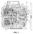
- FIG. 1is a cross-sectional elevational view of a power transmission incorporating one embodiment of the present invention.
- FIG. 2is a cross-sectional depiction of a power transmission similar to that shown in FIG. 1 .
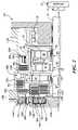
- FIG. 3is a cross-sectional depiction of another embodiment of the present invention.
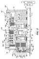
- FIG. 4is a cross-sectional depiction of a transmission incorporating yet still another embodiment of the present invention.
- FIG. 5is a cross-sectional depiction of a power transmission incorporating a further embodiment of the present invention.
- FIG. 6is a duplicate of FIG. 1 but with the reference numerals, lead lines and shading removed.
- a powertrain 10including an engine 12 , a conventional torque converter 14 , a power transmission 16 , and an output drive mechanism 18 .
- the engine 12is a conventional internal combustion prime mover well known to those skilled in the art.
- the torque converter 14is a conventional torque converter having an impeller 20 drivingly connected through an input shell and flex plate 22 with the engine 12 , a turbine 24 having associated therewith a conventional torque converter clutch 26 .
- the torque converter 14also includes a stator element 28 , which is grounded through a one-way device 30 with a front end wall or cover 32 of the transmission 16 .
- the turbine 24 and torque converter clutch 26are drivingly connected with a transmission input shaft 34 .
- the output drive mechanism 18includes meshing output gears 36 and 38 .
- the power transmission 16includes three planetary gearsets 40 , 42 , and 44 , and five torque-transmitting mechanisms 46 , 48 , 50 , 52 , and 54 .
- the planetary gearset 40includes a sun gear member 55 , a ring gear member 56 , and a planet carrier assembly member 58 , which is comprised of a plurality of pinion gears 60 that are rotatably mounted on a planet carrier member 62 .
- the sun gear member 55is connected through a housing or shell member 64 with a set of friction plates 66 , which are part of the torque-transmitting mechanism 46 .
- the planetary gearset 42includes a sun gear member 68 , a ring gear member 70 , and a planet carrier assembly member 72 .
- the planet carrier assembly member 72includes a plurality of pinion gears 74 rotatably mounted on a planet carrier member 76 and disposed in meshing relationship with the sun gear member 68 and the ring gear member 70 .
- the planet carrier member 76is continuously connected with the ring gear member 56 .
- the sun gear member 68is continuously drivingly connected with the input shaft 34 .
- the planetary gearset 44includes a sun gear member 78 , a ring gear member 80 , and a planet carrier assembly member 82 .
- the planet carrier assembly member 82includes a plurality of pinion gears 84 that are rotatably supported on a planet carrier member 86 .
- the planet carrier member 86is drivingly connected to a shell 88 , which is splined to a plurality of friction plates 90 that are components of the torque-transmitting mechanism 54 .
- the ring gear member 80is drivingly connected through a shell or housing 92 with the planet carrier member 62 .
- the planet carrier member 86is also drivingly connected through a sleeve shaft and hub 96 to a plurality of friction plates 98 that are components of the torque-transmitting mechanism 52 .
- the sun gear member 78is continuously drivingly connected with a hub 100 , which includes a shell portion 102 splined to a plurality of friction plates 104 , which are components of the torque-transmitting mechanism 50 .
- the hub portion 102is also drivingly connected with a plurality of friction plates 106 that are components of the torque-transmitting mechanism 48 .
- the planetary gearsets 40 , 42 , and 44 and torque-transmitting mechanisms 46 , 48 , 50 , 52 , and 54are housed within a transmission housing 108 , which is comprised of the front end cover 32 , a rear end cover or wall 110 , and a housing shell 112 .
- the rear end cover 110has an extension or boss 114 , which rotatably supports a sleeve portion 116 of the input shaft 34 .
- the extension 114 and sleeve portion 116include a plurality of hydraulic passages through which fluid to the torque-transmitting mechanisms 50 and 52 is directed.
- the rear end cover 110also has hydraulic passages formed therein, which supply fluid to the torque-transmitting mechanisms 48 and 54 .
- the shell 112has hydraulic passages formed therein, which supply fluid pressure to the torque-transmitting mechanism 46 .
- the ring gear member 80 and planet carrier member 62are continuously connected with the output gear 36 .
- the output gears 36 and 38drive the conventional output mechanism 18 .
- the output mechanism 18is adapted to provide drive axles through the front wheels of a power transmission in which the powertrain 10 is generally transversely mounted relative to the longitudinal axis of a vehicle, not shown.
- the torque-transmitting mechanism 46includes the friction plates 66 , a plurality of friction members or plates 118 , and a servomechanism 120 .
- the servomechanism 120includes a piston member 122 slidably disposed in a chamber 124 formed in the shell 112 .
- the piston 122is energized with fluid pressure to enforce frictional engagement between the plates 66 and 118 , thereby connecting the sun gear member 55 with the shell 112 to hold the sun gear member 55 stationary.
- the torque-transmitting mechanism 48includes the friction plates 106 , a plurality of friction plates 126 , and a servomechanism 128 .
- the servomechanism 128includes a piston 130 slidably disposed in a chamber 132 formed in the rear end cover 110 and an extension 134 , which is adapted to enforce frictional engagement between the plates 126 and 106 , thereby connecting the sun gear member 78 with the housing shell 112 .
- the torque-transmitting mechanism 50includes the friction plates 104 , a plurality of friction plates 136 , and a servomechanism 138 , which is comprised of a piston member 140 slidably disposed in a chamber 142 formed in the extension of the input shaft 34 .
- the piston 140has an extension 144 adapted to enforce engagement of the friction plates 104 and 136 when the piston 140 is pressurized.
- the torque-transmitting mechanism 50provides a drive connection between the input shaft 34 and the sun gear member 78 .
- the torque-transmitting mechanism 52includes the friction plates 98 , a plurality of friction plates 146 , and a servomechanism 147 having a piston member 148 .
- the piston 148is slidably disposed in a chamber 150 formed in the input shaft 34 and adapted to being pressurized to enforce engagement between the friction plates 98 and 146 , thereby providing a drive connection between the planet carrier member 86 , the ring gear member 70 , and the input shaft 34 .
- the torque-transmitting mechanism 54includes the friction plates 90 , a plurality of friction plates 152 , and a servomechanism 154 .
- the servomechanism 154includes a piston 156 slidably disposed in a chamber 158 formed in the rear end cover 110 , and a piston extension 160 , which is adapted to enforce frictional engagement between the friction plates 90 and 152 to thereby connect the planet carrier member 86 and the ring gear member 70 with the shell 112 .
- the torque-transmitting mechanisms 46 , 48 , 50 , 52 , and 54are selectively engaged in combinations of two to establish six forward speed ratios and one reverse speed ratio between the input shaft 34 and the output mechanism 18 .
- the torque-transmitting mechanism 46is engaged for the first, second, third, and fourth forward speed ratios;
- the torque-transmitting mechanism 52is engaged for the fourth, fifth, and sixth forward speed ratios;
- the torque-transmitting mechanism 54is engaged for the first forward speed ratio and the reverse speed ratio;
- the torque-transmitting mechanism 48is engaged for the second and sixth forward speed ratios;
- the torque-transmitting mechanism 50is engaged for the third and fifth forward speed ratios and the reverse speed ratio.
- a one-way mechanism 162is disposed between the planet carrier member 86 and the shell 112 to provide a non-coast breaking low ratio, if desired.
- the transmissions shown in FIGS. 1 and 2provide four servomechanisms disposed within or rotatably supported on the rear end cover 110 , and the servomechanism 120 for the fifth torque-transmitting mechanism 46 is supported in the shell 112 .
- the friction plates for the torque-transmitting mechanisms 46 , 48 , and 54have one set thereof drivingly connected with the shell 112 and the other set respectively connected with the appropriate gear members as described above.
- the torque-transmitting mechanisms 50 and 52have one set of friction plates drivingly connected with the input shaft 34 and the other set of friction plates drivingly connected with the respective gear members as described above.
- torque-transmitting mechanisms 46 , 54 , and 48are stationary type torque-transmitting mechanisms, commonly termed brakes, and the torque-transmitting mechanisms 50 and 52 are rotating-type torque-transmitting mechanisms, commonly termed clutches.
- the powertrain 10 A shown in FIG. 2is a more diagrammatic presentation of the powertrain 10 shown in FIG. 1 .
- the corresponding components of the powertrain 10 Ahave been given the same numerical designation with an “A” suffix while the same corresponding parts, such as the gearing members, have been given the numerical designation.
- the powertrain 10 B shown in FIG. 3includes the engine 12 , the torque converter 14 , a planetary transmission 16 B, the input shaft 34 , the three planetary gearsets 40 , 42 , and 44 , and five torque-transmitting mechanisms 46 B, 48 B, 50 B, 52 B, and 54 B.
- the torque-transmitting mechanismsprovide the same control functions for the powertrain 10 B as were performed by their corresponding members in the powertrain 10 of FIG. 1 .
- the torque-transmitting mechanisms of FIG. 3have been rearranged and do have some physical differences.
- the torque-transmitting mechanism 46 Bis similarly disposed as the torque-transmitting mechanism 46 . That is, the servomechanism 120 B is supported on the shell 112 B.
- the servomechanism 154 B of the torque-transmitting mechanism 54 Bis also supported in the shell 112 B and the servomechanism 128 B of the torque-transmitting mechanism 48 B is supported on the shell 112 B.
- the servomechanisms 128 B and 154 Bare disposed back-to-back such that the piston 156 B of torque-transmitting mechanism 54 B extends rightward when energized and the piston 130 B of the torque-transmitting mechanism 48 B extends leftward when energized.
- the torque-transmitting mechanisms 50 B and 52 Bhave their respective servomechanisms 138 B and 147 B supported on the rear end cover 110 B.
- the piston 140 B of the servomechanism 138 Bis stationary within the rear end cover 101 B.
- the servomechanism 138 Bincludes an apply plate 200 , which is rotatably supported on a needle bearing 202 relative to the piston 140 B.
- the apply plate 200rotates with a housing 204 , which is drivingly connected with the input shaft 34 .
- the friction plates 136 Bare drivingly connected with the housing 204 and the friction plates 104 B are drivingly connected with an extension of the sun gear member 78 .
- the servomechanism 147 B of the torque-transmitting mechanism 52 Bincludes a piston 206 supported within the rear end cover 110 B.
- the piston 206is a nonrotating member and is separated from an apply plate 208 by a needle bearing 210 .
- the apply plate 208is adapted to engage the friction plates 146 B and 98 B to provide engagement of the torque-transmitting mechanism 52 B.
- the apply plate 208 and friction plates 98 Bare drivingly connected with the housing 204 and the friction plates 146 B are drivingly connected with an extension of the carrier 86 and ring gear member 70 .
- the rear end cover 110 Bis simplified in structure in that less hydraulic passages need to be formed therein.
- the hydraulic passagesare formed directly from the control mechanism to the torque-transmitting mechanisms 48 B, 46 B, and 54 B through the shell 112 B.
- the hydraulic connections with the servomechanisms 138 B and 147 Bare simplified in that rotating seals are no longer required. In fact, there are no rotating seals at all required for any of the servomechanisms for the transmission shown in powertrain 10 B shown in FIG 3 .
- a powertrain 10 C shown in FIG. 4is similar to the powertrain 10 B shown in FIG. 3 and operates in the same manner as the powertrain described in powertrain 10 . That is, the powertrain 10 C has the three planetary gearsets 40 , 42 , and 44 and five torque-transmitting mechanisms 46 C, 48 C, 50 C, 52 C and 54 C. These mechanisms are operated in a manner similar to that described for powertrain 10 in order to establish six forward speed ratios and one reverse speed ratio within the transmission 16 C. The primary difference between the transmissions 16 C and 16 B are the position of the torque-transmitting mechanisms 46 C and 54 C.
- the servomechanisms 120 C and 154 Care arranged back-to-back and disposed on the shell 112 C.
- the servomechanism 128 C of the torque-transmitting mechanism 48 Cis disposed substantially the same as the torque-transmitting mechanism 48 B.
- the torque-transmitting mechanisms 50 C and 52 Care substantially identical with their corresponding torque-transmitting mechanisms 50 B and 52 B, which were described in FIG. 3 . That is, the pistons 140 C and 206 C are stationary within the rear end cover 110 C.
- the torque-transmitting mechanisms for the powertrain 10 Cdo not require rotating seals between the control mechanism and the apply chambers for each of the pistons of the torque-transmitting mechanisms.
- a powertrain 10 D shown in FIG. 5is similar to the powertrain 10 shown in FIG. 1 and the powertrains 10 B and 10 C shown in FIGS. 3 and 4 .
- the torque-transmitting mechanism 46 Dis positioned essentially the same as the torque-transmitting mechanism 46 and is supported in the shell 112 D.
- the torque-transmitting mechanisms 54 D and 48 Dare substantially similar to the torque-transmitting mechanisms 54 and 48 , which are shown in FIG. 1 .
- the torque-transmitting mechanisms 50 D and 52 Dare nested axially instead of being nested radially as shown in FIGS. 1 , 2 , 3 , and 4 .
- the torque-transmitting mechanisms 50 D and 52 Ddo, however, have stationary pistons similar to the torque-transmitting mechanisms 50 B, 50 C, 52 B, and 52 C.
- the torque-transmitting mechanism 52 Dhas a housing 212 , which is secured with the rear cover 110 D such that the piston 148 D is stationary within the housing 212 and cooperates therewith to form an apply chamber 150 D for the servomechanism 147 D.
- the torque-transmitting mechanisms 50 D and 52 Deach have an apply plate 200 D and 208 D that are rotatably supported by bearings 202 D and 210 D, respectively.
- the apply plates 200 D and 208 Dare rotatable with a housing or extension 204 D, which is drivingly connected with the input shaft 34 .
- the servomechanisms for the torque-transmitting mechanisms 54 D, 48 D, 50 D, and 52 Dhave hydraulic passages formed within the end cover 110 D in a manner similar to that shown in FIG. 1 ; however, there is no need for rotating seals for the transmission 16 D, which is a difference compared with the powertrain 10 .
- each of the above-described powertrainshas compact power transmission arrangements.
- the input and output of these power transmissionsare both at the front or engine end of the transmission.
- the output for these transmissions including the output gears 36 and 38is adaptable to transverse front wheel drive applications.
- the longitudinal dimension or length of the powertrainis a critical design factor as is the barrel diameter or overall outer diameter of the package.
- Each of the transmissions described aboveprovide for a considerably shortened axial length while permitting a slightly larger barrel size for each of the power transmissions described.
Landscapes
- Engineering & Computer Science (AREA)
- General Engineering & Computer Science (AREA)
- Mechanical Engineering (AREA)
- Structure Of Transmissions (AREA)
- Hydraulic Clutches, Magnetic Clutches, Fluid Clutches, And Fluid Joints (AREA)
Abstract
Description
Claims (6)
Priority Applications (2)
| Application Number | Priority Date | Filing Date | Title |
|---|---|---|---|
| US10/693,262US6960150B2 (en) | 2003-10-24 | 2003-10-24 | Power transmission for a vehicle |
| DE102004050123ADE102004050123A1 (en) | 2003-10-24 | 2004-10-14 | Power shift transmission for a vehicle |
Applications Claiming Priority (1)
| Application Number | Priority Date | Filing Date | Title |
|---|---|---|---|
| US10/693,262US6960150B2 (en) | 2003-10-24 | 2003-10-24 | Power transmission for a vehicle |
Publications (2)
| Publication Number | Publication Date |
|---|---|
| US20050090360A1 US20050090360A1 (en) | 2005-04-28 |
| US6960150B2true US6960150B2 (en) | 2005-11-01 |
Family
ID=34522345
Family Applications (1)
| Application Number | Title | Priority Date | Filing Date |
|---|---|---|---|
| US10/693,262Expired - LifetimeUS6960150B2 (en) | 2003-10-24 | 2003-10-24 | Power transmission for a vehicle |
Country Status (2)
| Country | Link |
|---|---|
| US (1) | US6960150B2 (en) |
| DE (1) | DE102004050123A1 (en) |
Cited By (25)
| Publication number | Priority date | Publication date | Assignee | Title |
|---|---|---|---|---|
| US20050137044A1 (en)* | 2003-12-18 | 2005-06-23 | Shaun Knowles | Multiple speed automatic transmission for motor vehicle |
| US20050227804A1 (en)* | 2002-12-27 | 2005-10-13 | Kazumichi Kayama | Automatic speed changer |
| US20050245344A1 (en)* | 2002-12-27 | 2005-11-03 | Kazumichi Kayama | Automatic speed changer |
| US20060128517A1 (en)* | 2003-07-31 | 2006-06-15 | Peter Tiesler | Multi-stage automatic transmission with three planetary gearwheel assemblies |
| US20080085812A1 (en)* | 2006-10-09 | 2008-04-10 | Wittkopp Scott H | Multi-speed transmission |
| US20080085807A1 (en)* | 2006-10-09 | 2008-04-10 | Wittkopp Scott H | Multi-speed transmission |
| US20080085813A1 (en)* | 2006-10-09 | 2008-04-10 | Hart James M | Multi-speed transmission |
| US20080085808A1 (en)* | 2006-10-09 | 2008-04-10 | Hart James M | Multi-speed transmission |
| US20080085811A1 (en)* | 2006-10-09 | 2008-04-10 | Hart James M | Multi-speed transmission |
| US20080085810A1 (en)* | 2006-10-09 | 2008-04-10 | Hart James M | Multi-speed transmission |
| US20080085806A1 (en)* | 2006-10-09 | 2008-04-10 | Wittkopp Scott H | Multi-speed transmission |
| US20080085809A1 (en)* | 2006-10-09 | 2008-04-10 | Wittkopp Scott H | Multi-speed transmission |
| US20080085805A1 (en)* | 2006-10-09 | 2008-04-10 | Wittkopp Scott H | Multi-speed transmission |
| US20090075778A1 (en)* | 2007-09-19 | 2009-03-19 | Zf Friedrichshafen Ab | Connection of a planetary gear drive with the spur gear and/or central gear in an automatic transmission |
| US20090215571A1 (en)* | 2008-02-21 | 2009-08-27 | Gm Global Technology Operations, Inc. | Multi-speed transmission for a front wheel drive vehicle |
| CN101566217A (en)* | 2009-06-03 | 2009-10-28 | 奇瑞汽车股份有限公司 | 6-speed automatic transmission and transmission system thereof |
| CN101566216A (en)* | 2009-06-03 | 2009-10-28 | 奇瑞汽车股份有限公司 | 6-speed automatic transmission for automobile and transmission system thereof |
| US20100075794A1 (en)* | 2008-09-24 | 2010-03-25 | Luk Lamellen Und Kupplungsbau Beteiligungs Kg | Transmission actuation system |
| US20100240489A1 (en)* | 2009-03-17 | 2010-09-23 | Gm Global Technology Operations, Inc. | Clutch and gear arrangement for a front wheel drive vehicle |
| US20100267514A1 (en)* | 2007-03-16 | 2010-10-21 | Gm Global Technology Operations, Inc. | Multi-speed transmission |
| US20110067516A1 (en)* | 2009-09-18 | 2011-03-24 | Frait Steve A | Control for an Automatic Transmission |
| US8083630B2 (en) | 2008-12-22 | 2011-12-27 | Caterpillar Inc. | Compact planetary transmission |
| US8202194B2 (en) | 2009-03-17 | 2012-06-19 | GM Global Technology Operations LLC | Clutch and gear arrangement for a front wheel drive vehicle |
| US8784258B2 (en) | 2010-12-01 | 2014-07-22 | Ford Global Technologies, Llc | Planetary power transmission |
| US9163704B2 (en) | 2011-01-10 | 2015-10-20 | Gm Global Technology Operations, Llc | Clutch and gear arrangement for a front wheel drive vehicle |
Families Citing this family (3)
| Publication number | Priority date | Publication date | Assignee | Title |
|---|---|---|---|---|
| JP4924474B2 (en)* | 2008-02-27 | 2012-04-25 | マツダ株式会社 | Automatic transmission |
| WO2011094223A1 (en) | 2010-01-26 | 2011-08-04 | Martin Burgbacher | Gear assembly for motor vehicle |
| CN101832371A (en)* | 2010-06-02 | 2010-09-15 | 奇瑞汽车股份有限公司 | Arrangement of 6AT power drive system |
Citations (9)
| Publication number | Priority date | Publication date | Assignee | Title |
|---|---|---|---|---|
| EP0039368A1 (en)* | 1979-08-08 | 1981-11-11 | Iseki & Co., Ltd. | Reduction gear shifting device |
| US4426891A (en)* | 1980-03-21 | 1984-01-24 | Toyota Jidosha Kogyo Kabushiki Kaisha | Radially outward return spring for transmission brake |
| JPH03157543A (en)* | 1989-11-13 | 1991-07-05 | Kubota Corp | planetary transmission |
| US5106352A (en) | 1989-12-18 | 1992-04-21 | Lepelletier Pierre A G | Multispeed automatic transmission for automobile vehicles |
| US6135912A (en) | 1998-09-01 | 2000-10-24 | Aisin Aw Co., Ltd. | Automatic transmission for a vehicle |
| US6287233B1 (en)* | 1999-11-23 | 2001-09-11 | General Motors Corporation | Powertrain with a five speed planetary transmission |
| US6468179B1 (en)* | 2001-05-11 | 2002-10-22 | General Motors Corporation | Six speed planetary transmission with two overdrive ratios |
| US6572507B1 (en) | 1999-03-22 | 2003-06-03 | Zf Friedrichshafen Ag | Automatic transmission for motor vehicles |
| US6811513B1 (en)* | 2003-04-15 | 2004-11-02 | General Motors Corporation | Multi-speed power transmission |
- 2003
- 2003-10-24USUS10/693,262patent/US6960150B2/ennot_activeExpired - Lifetime
- 2004
- 2004-10-14DEDE102004050123Apatent/DE102004050123A1/ennot_activeCeased
Patent Citations (9)
| Publication number | Priority date | Publication date | Assignee | Title |
|---|---|---|---|---|
| EP0039368A1 (en)* | 1979-08-08 | 1981-11-11 | Iseki & Co., Ltd. | Reduction gear shifting device |
| US4426891A (en)* | 1980-03-21 | 1984-01-24 | Toyota Jidosha Kogyo Kabushiki Kaisha | Radially outward return spring for transmission brake |
| JPH03157543A (en)* | 1989-11-13 | 1991-07-05 | Kubota Corp | planetary transmission |
| US5106352A (en) | 1989-12-18 | 1992-04-21 | Lepelletier Pierre A G | Multispeed automatic transmission for automobile vehicles |
| US6135912A (en) | 1998-09-01 | 2000-10-24 | Aisin Aw Co., Ltd. | Automatic transmission for a vehicle |
| US6572507B1 (en) | 1999-03-22 | 2003-06-03 | Zf Friedrichshafen Ag | Automatic transmission for motor vehicles |
| US6287233B1 (en)* | 1999-11-23 | 2001-09-11 | General Motors Corporation | Powertrain with a five speed planetary transmission |
| US6468179B1 (en)* | 2001-05-11 | 2002-10-22 | General Motors Corporation | Six speed planetary transmission with two overdrive ratios |
| US6811513B1 (en)* | 2003-04-15 | 2004-11-02 | General Motors Corporation | Multi-speed power transmission |
Cited By (59)
| Publication number | Priority date | Publication date | Assignee | Title |
|---|---|---|---|---|
| US20050227804A1 (en)* | 2002-12-27 | 2005-10-13 | Kazumichi Kayama | Automatic speed changer |
| US20050245344A1 (en)* | 2002-12-27 | 2005-11-03 | Kazumichi Kayama | Automatic speed changer |
| US7226380B2 (en)* | 2002-12-27 | 2007-06-05 | Aisin Aw Co., Ltd. | Automatic speed changer |
| US7422538B2 (en)* | 2002-12-27 | 2008-09-09 | Aisin Aw Co., Ltd. | Automatic speed changer |
| US20060128517A1 (en)* | 2003-07-31 | 2006-06-15 | Peter Tiesler | Multi-stage automatic transmission with three planetary gearwheel assemblies |
| US7217218B2 (en) | 2003-07-31 | 2007-05-15 | Zf Friedrichshafen Ag | Multi-stage automatic transmission with three planetary gearwheel assemblies |
| US20070149343A1 (en)* | 2003-07-31 | 2007-06-28 | Zf Friedrichshafen Ag | Multi-stage automatic transmission with three planetary gearwheel assemblies |
| US7255661B2 (en) | 2003-07-31 | 2007-08-14 | Zf Friedrichshafen Ag | Multi-stage automatic transmission with three planetary gearwheel assemblies |
| US7335127B2 (en) | 2003-07-31 | 2008-02-26 | Zf Friedrichshafen Ag | Multi-stage automatic transmission with three planetary gearwheel assemblies |
| US20050137044A1 (en)* | 2003-12-18 | 2005-06-23 | Shaun Knowles | Multiple speed automatic transmission for motor vehicle |
| US7083537B2 (en)* | 2003-12-18 | 2006-08-01 | Ford Global Technologies, Llc | Multiple speed automatic transmission for motor vehicle |
| US7789790B2 (en) | 2006-10-09 | 2010-09-07 | Gm Global Technology Operations, Inc. | Multi-speed transmission |
| US7837591B2 (en) | 2006-10-09 | 2010-11-23 | Gm Global Technology Operations, Inc. | Multi-speed transmission |
| US20080085813A1 (en)* | 2006-10-09 | 2008-04-10 | Hart James M | Multi-speed transmission |
| US20080085808A1 (en)* | 2006-10-09 | 2008-04-10 | Hart James M | Multi-speed transmission |
| US20080085811A1 (en)* | 2006-10-09 | 2008-04-10 | Hart James M | Multi-speed transmission |
| US20080085810A1 (en)* | 2006-10-09 | 2008-04-10 | Hart James M | Multi-speed transmission |
| US20080085806A1 (en)* | 2006-10-09 | 2008-04-10 | Wittkopp Scott H | Multi-speed transmission |
| US20080085809A1 (en)* | 2006-10-09 | 2008-04-10 | Wittkopp Scott H | Multi-speed transmission |
| US20080085805A1 (en)* | 2006-10-09 | 2008-04-10 | Wittkopp Scott H | Multi-speed transmission |
| US7867127B2 (en) | 2006-10-09 | 2011-01-11 | Gm Global Technology Operations, Inc. | Multi-speed transmission |
| US7862464B2 (en) | 2006-10-09 | 2011-01-04 | Gm Global Technology Operations, Inc. | Multi-speed transmission |
| US7862463B2 (en) | 2006-10-09 | 2011-01-04 | Gm Global Technology Operations, Inc. | Multi-speed transmission |
| US20080085807A1 (en)* | 2006-10-09 | 2008-04-10 | Wittkopp Scott H | Multi-speed transmission |
| US7695396B2 (en) | 2006-10-09 | 2010-04-13 | Gm Global Technologies Operations, Inc. | Multi-speed transmission |
| US7789787B2 (en) | 2006-10-09 | 2010-09-07 | Gm Global Technology Operations, Inc. | Multi-speed transmission |
| US7789789B2 (en) | 2006-10-09 | 2010-09-07 | Gm Global Technology Operations, Inc. | Multi-speed transmission |
| US7789788B2 (en) | 2006-10-09 | 2010-09-07 | Gm Global Technology Operations, Inc. | Multi-speed transmission |
| US20080085812A1 (en)* | 2006-10-09 | 2008-04-10 | Wittkopp Scott H | Multi-speed transmission |
| US7867128B2 (en) | 2007-03-16 | 2011-01-11 | Gm Global Technology Operations, Inc. | Multi-speed transmission |
| US7862467B2 (en) | 2007-03-16 | 2011-01-04 | Gm Global Technology Operations, Inc. | Multi-speed transmission |
| US20100267515A1 (en)* | 2007-03-16 | 2010-10-21 | Gm Global Technology Operations, Inc. | Multi-speed transmission |
| US20100267516A1 (en)* | 2007-03-16 | 2010-10-21 | Gm Global Technology Operations, Inc. | Multi-speed transmission |
| US20100267517A1 (en)* | 2007-03-16 | 2010-10-21 | Gm Global Technology Operations, Inc. | Multi-speed transmission |
| US20100267513A1 (en)* | 2007-03-16 | 2010-10-21 | Gm Global Technology Operations, Inc. | Multi-speed transmission |
| US20100267514A1 (en)* | 2007-03-16 | 2010-10-21 | Gm Global Technology Operations, Inc. | Multi-speed transmission |
| US7878940B2 (en) | 2007-03-16 | 2011-02-01 | GM Global Technology Operations LLC | Multi-speed transmission |
| US7867130B2 (en) | 2007-03-16 | 2011-01-11 | Gm Global Technology Operations, Inc. | Multi-speed transmission |
| US7867129B2 (en) | 2007-03-16 | 2011-01-11 | Gm Global Technology Operations, Inc. | Multi-speed transmission |
| US7862466B2 (en) | 2007-03-16 | 2011-01-04 | Gm Global Technology Operations, Inc. | Multi-speed transmission |
| US20090075778A1 (en)* | 2007-09-19 | 2009-03-19 | Zf Friedrichshafen Ab | Connection of a planetary gear drive with the spur gear and/or central gear in an automatic transmission |
| US20090215571A1 (en)* | 2008-02-21 | 2009-08-27 | Gm Global Technology Operations, Inc. | Multi-speed transmission for a front wheel drive vehicle |
| US8025605B2 (en) | 2008-02-21 | 2011-09-27 | GM Global Technology Operations LLC | Multi-speed transmission for a front wheel drive vehicle |
| US20100075794A1 (en)* | 2008-09-24 | 2010-03-25 | Luk Lamellen Und Kupplungsbau Beteiligungs Kg | Transmission actuation system |
| US8083630B2 (en) | 2008-12-22 | 2011-12-27 | Caterpillar Inc. | Compact planetary transmission |
| US20100240489A1 (en)* | 2009-03-17 | 2010-09-23 | Gm Global Technology Operations, Inc. | Clutch and gear arrangement for a front wheel drive vehicle |
| US8496557B2 (en) | 2009-03-17 | 2013-07-30 | GM Global Technology Operations LLC | Clutch and gear arrangement for a front wheel drive vehicle |
| US8550954B2 (en) | 2009-03-17 | 2013-10-08 | GM Global Technology Operations LLC | Clutch and gear arrangement for a front wheel drive vehicle |
| US8449428B2 (en) | 2009-03-17 | 2013-05-28 | GM Global Technology Operations LLC | Clutch and gear arrangement for a front wheel drive vehicle |
| US8465389B2 (en) | 2009-03-17 | 2013-06-18 | GM Global Technology Operations LLC | Clutch and gear arrangement for a front wheel drive vehicle |
| US8202191B2 (en) | 2009-03-17 | 2012-06-19 | GM Global Technology Operations LLC | Clutch and gear arrangement for a front wheel drive vehicle |
| US8202194B2 (en) | 2009-03-17 | 2012-06-19 | GM Global Technology Operations LLC | Clutch and gear arrangement for a front wheel drive vehicle |
| US8353802B2 (en) | 2009-03-17 | 2013-01-15 | GM Global Technology Operations LLC | Clutch and gear arrangement for a front wheel drive vehicle |
| CN101566217A (en)* | 2009-06-03 | 2009-10-28 | 奇瑞汽车股份有限公司 | 6-speed automatic transmission and transmission system thereof |
| CN101566216A (en)* | 2009-06-03 | 2009-10-28 | 奇瑞汽车股份有限公司 | 6-speed automatic transmission for automobile and transmission system thereof |
| US8092330B2 (en) | 2009-09-18 | 2012-01-10 | Ford Global Technologies, Llc | Control for an automatic transmission |
| US20110067516A1 (en)* | 2009-09-18 | 2011-03-24 | Frait Steve A | Control for an Automatic Transmission |
| US8784258B2 (en) | 2010-12-01 | 2014-07-22 | Ford Global Technologies, Llc | Planetary power transmission |
| US9163704B2 (en) | 2011-01-10 | 2015-10-20 | Gm Global Technology Operations, Llc | Clutch and gear arrangement for a front wheel drive vehicle |
Also Published As
| Publication number | Publication date |
|---|---|
| US20050090360A1 (en) | 2005-04-28 |
| DE102004050123A1 (en) | 2005-06-02 |
Similar Documents
| Publication | Publication Date | Title |
|---|---|---|
| US6960150B2 (en) | Power transmission for a vehicle | |
| US6929576B2 (en) | Power transmission for a vehicle | |
| US6083135A (en) | Multiple speed overdrive transmission for a motor vehicle | |
| US7044881B2 (en) | Automatic transmission | |
| US7841960B2 (en) | Eight speed planetary kinematic arrangement with two rotating clutches | |
| US6913556B2 (en) | Power transmission for a vehicle | |
| US5823051A (en) | Multi-speed power transmission | |
| US9528573B2 (en) | Multi-speed transmission | |
| US7789792B2 (en) | Multi-speed transmission | |
| US5039305A (en) | Multiple ratio compact transaxle assembly for automotive vehicles | |
| US7527576B2 (en) | Multi-step transmission | |
| US5984825A (en) | Power transmission with two simple planetary gearsets | |
| AU2018208626A1 (en) | Automatic transmission | |
| US6923742B2 (en) | Power transmission for a vehicle | |
| AU766974B2 (en) | Power train for automatic transmissions | |
| CN101375084B (en) | Automatic transmission | |
| US10465772B2 (en) | Planetary gear train of automatic transmission for vehicle | |
| JP5030504B2 (en) | Multistage automatic transmission | |
| JPWO2007114215A1 (en) | Automatic transmission | |
| US9945449B2 (en) | Multi-speed transmission | |
| US20170159775A1 (en) | Planetary gear train of automatic transmission for vehicles | |
| US5836850A (en) | Four speed power transmission | |
| US5470284A (en) | Automatic transmission | |
| US6468179B1 (en) | Six speed planetary transmission with two overdrive ratios | |
| KR20050120991A (en) | Multi stage automatic transmission for a vehicle |
Legal Events
| Date | Code | Title | Description |
|---|---|---|---|
| AS | Assignment | Owner name:GENERAL MOTORS CORPORATION, MICHIGAN Free format text:ASSIGNMENT OF ASSIGNORS INTEREST;ASSIGNORS:ARMSTRONG, PAULA J.;WITTKOPP, SCOTT H.;REEL/FRAME:014569/0651 Effective date:20031107 | |
| STCF | Information on status: patent grant | Free format text:PATENTED CASE | |
| AS | Assignment | Owner name:GM GLOBAL TECHNOLOGY OPERATIONS, INC., MICHIGAN Free format text:ASSIGNMENT OF ASSIGNORS INTEREST;ASSIGNOR:GENERAL MOTORS CORPORATION;REEL/FRAME:022117/0022 Effective date:20050119 Owner name:GM GLOBAL TECHNOLOGY OPERATIONS, INC.,MICHIGAN Free format text:ASSIGNMENT OF ASSIGNORS INTEREST;ASSIGNOR:GENERAL MOTORS CORPORATION;REEL/FRAME:022117/0022 Effective date:20050119 | |
| AS | Assignment | Owner name:UNITED STATES DEPARTMENT OF THE TREASURY, DISTRICT Free format text:SECURITY AGREEMENT;ASSIGNOR:GM GLOBAL TECHNOLOGY OPERATIONS, INC.;REEL/FRAME:022201/0547 Effective date:20081231 Owner name:UNITED STATES DEPARTMENT OF THE TREASURY,DISTRICT Free format text:SECURITY AGREEMENT;ASSIGNOR:GM GLOBAL TECHNOLOGY OPERATIONS, INC.;REEL/FRAME:022201/0547 Effective date:20081231 | |
| FPAY | Fee payment | Year of fee payment:4 | |
| AS | Assignment | Owner name:CITICORP USA, INC. AS AGENT FOR BANK PRIORITY SECU Free format text:SECURITY AGREEMENT;ASSIGNOR:GM GLOBAL TECHNOLOGY OPERATIONS, INC.;REEL/FRAME:022553/0399 Effective date:20090409 Owner name:CITICORP USA, INC. AS AGENT FOR HEDGE PRIORITY SEC Free format text:SECURITY AGREEMENT;ASSIGNOR:GM GLOBAL TECHNOLOGY OPERATIONS, INC.;REEL/FRAME:022553/0399 Effective date:20090409 | |
| AS | Assignment | Owner name:GM GLOBAL TECHNOLOGY OPERATIONS, INC., MICHIGAN Free format text:RELEASE BY SECURED PARTY;ASSIGNOR:UNITED STATES DEPARTMENT OF THE TREASURY;REEL/FRAME:023124/0470 Effective date:20090709 Owner name:GM GLOBAL TECHNOLOGY OPERATIONS, INC.,MICHIGAN Free format text:RELEASE BY SECURED PARTY;ASSIGNOR:UNITED STATES DEPARTMENT OF THE TREASURY;REEL/FRAME:023124/0470 Effective date:20090709 | |
| AS | Assignment | Owner name:GM GLOBAL TECHNOLOGY OPERATIONS, INC., MICHIGAN Free format text:RELEASE BY SECURED PARTY;ASSIGNORS:CITICORP USA, INC. AS AGENT FOR BANK PRIORITY SECURED PARTIES;CITICORP USA, INC. AS AGENT FOR HEDGE PRIORITY SECURED PARTIES;REEL/FRAME:023127/0273 Effective date:20090814 Owner name:GM GLOBAL TECHNOLOGY OPERATIONS, INC.,MICHIGAN Free format text:RELEASE BY SECURED PARTY;ASSIGNORS:CITICORP USA, INC. AS AGENT FOR BANK PRIORITY SECURED PARTIES;CITICORP USA, INC. AS AGENT FOR HEDGE PRIORITY SECURED PARTIES;REEL/FRAME:023127/0273 Effective date:20090814 | |
| AS | Assignment | Owner name:UNITED STATES DEPARTMENT OF THE TREASURY, DISTRICT Free format text:SECURITY AGREEMENT;ASSIGNOR:GM GLOBAL TECHNOLOGY OPERATIONS, INC.;REEL/FRAME:023156/0001 Effective date:20090710 Owner name:UNITED STATES DEPARTMENT OF THE TREASURY,DISTRICT Free format text:SECURITY AGREEMENT;ASSIGNOR:GM GLOBAL TECHNOLOGY OPERATIONS, INC.;REEL/FRAME:023156/0001 Effective date:20090710 | |
| AS | Assignment | Owner name:UAW RETIREE MEDICAL BENEFITS TRUST, MICHIGAN Free format text:SECURITY AGREEMENT;ASSIGNOR:GM GLOBAL TECHNOLOGY OPERATIONS, INC.;REEL/FRAME:023161/0911 Effective date:20090710 Owner name:UAW RETIREE MEDICAL BENEFITS TRUST,MICHIGAN Free format text:SECURITY AGREEMENT;ASSIGNOR:GM GLOBAL TECHNOLOGY OPERATIONS, INC.;REEL/FRAME:023161/0911 Effective date:20090710 | |
| AS | Assignment | Owner name:GM GLOBAL TECHNOLOGY OPERATIONS, INC., MICHIGAN Free format text:RELEASE BY SECURED PARTY;ASSIGNOR:UNITED STATES DEPARTMENT OF THE TREASURY;REEL/FRAME:025245/0347 Effective date:20100420 Owner name:GM GLOBAL TECHNOLOGY OPERATIONS, INC., MICHIGAN Free format text:RELEASE BY SECURED PARTY;ASSIGNOR:UAW RETIREE MEDICAL BENEFITS TRUST;REEL/FRAME:025311/0725 Effective date:20101026 | |
| AS | Assignment | Owner name:WILMINGTON TRUST COMPANY, DELAWARE Free format text:SECURITY AGREEMENT;ASSIGNOR:GM GLOBAL TECHNOLOGY OPERATIONS, INC.;REEL/FRAME:025327/0262 Effective date:20101027 | |
| AS | Assignment | Owner name:GM GLOBAL TECHNOLOGY OPERATIONS LLC, MICHIGAN Free format text:CHANGE OF NAME;ASSIGNOR:GM GLOBAL TECHNOLOGY OPERATIONS, INC.;REEL/FRAME:025780/0902 Effective date:20101202 | |
| FPAY | Fee payment | Year of fee payment:8 | |
| AS | Assignment | Owner name:GM GLOBAL TECHNOLOGY OPERATIONS LLC, MICHIGAN Free format text:RELEASE BY SECURED PARTY;ASSIGNOR:WILMINGTON TRUST COMPANY;REEL/FRAME:034371/0676 Effective date:20141017 | |
| FPAY | Fee payment | Year of fee payment:12 |